Open HardwareAssembly Instructions
Guides for installation and assembly of the LulzBot line of products made by FAME 3D LLC.
Guides for installation and assembly of the LulzBot line of products made by FAME 3D LLC.
Materials Needed:
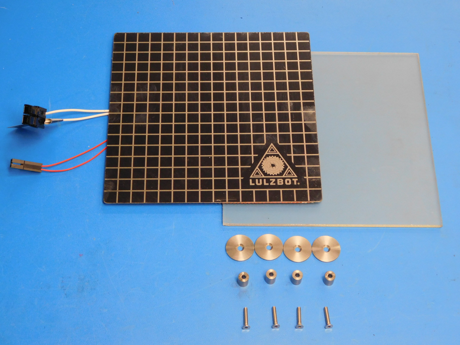
1x- [AS-HB0008] Mini Modular Print Bed Heater, no felt
1x- [AS-HB0001] Mini Glass/PEI Print surface
4x- [PP-MP0082] Bed Leveling Washers
4x- [HD-MS0453] 11.11mm Spacers for M3 Screws
4x- [HD-BT0082] M3x16 Stainless FHCS
Tools Needed:
2mm Hex Driver
Torque driver
Before installing the Modular Bed Plate System - verify that the flat head fasteners for the left bearing holder and button heads for the belt clamp are properly torqued to 5 in·lbs and that the remaining 6 button heads are torqued to 3 in·lbs
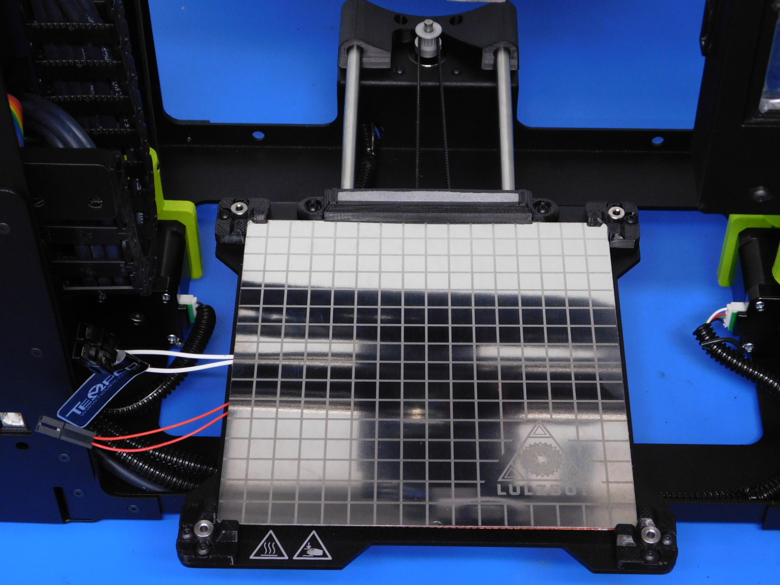
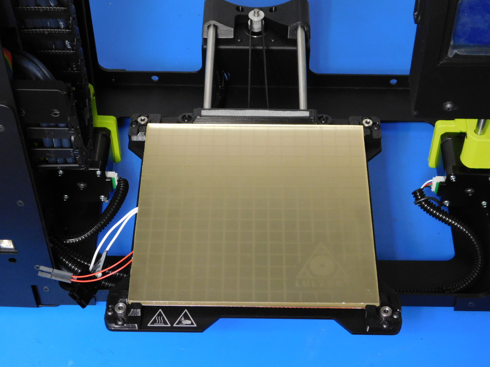
Place the four 11.11mm Spacers [HD-MS0453] into the holes in the Ninjaflex bed corners (see picture).
Place the Mini Modular Print Bed Heater [AS-HB0008] on the bed corners oriented with the wires coming out the left side of the heat bed (see picture).
Align the Bed Corners with the edges of the Modular Bed Heater; the front two bed corners should be flush with the edge of the Bed Plate.
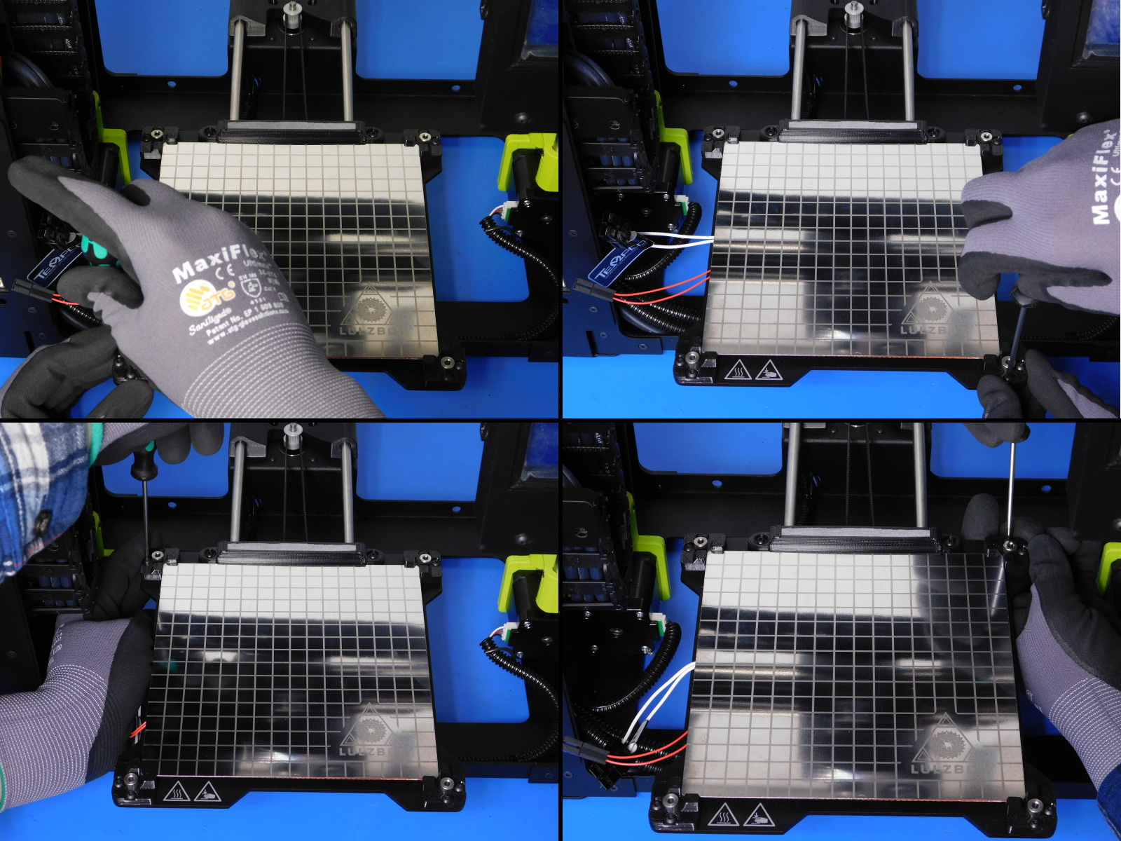
Tighten the two screws on each bed corner until the end of the screw is flush with the bottom of the Bed Plate.
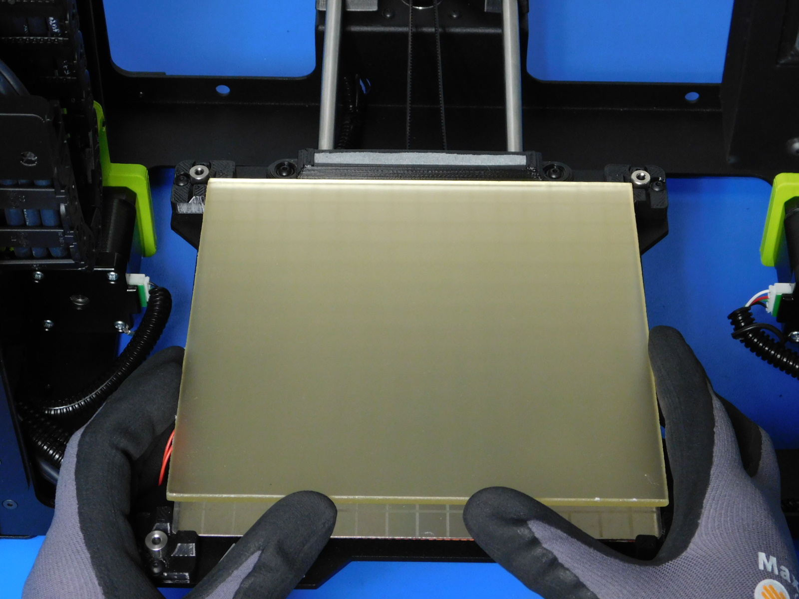
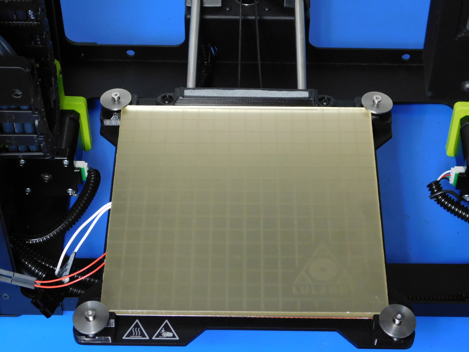
Place the Glass/PEI Print Surface [AS-HB0001] over the Bed Heater
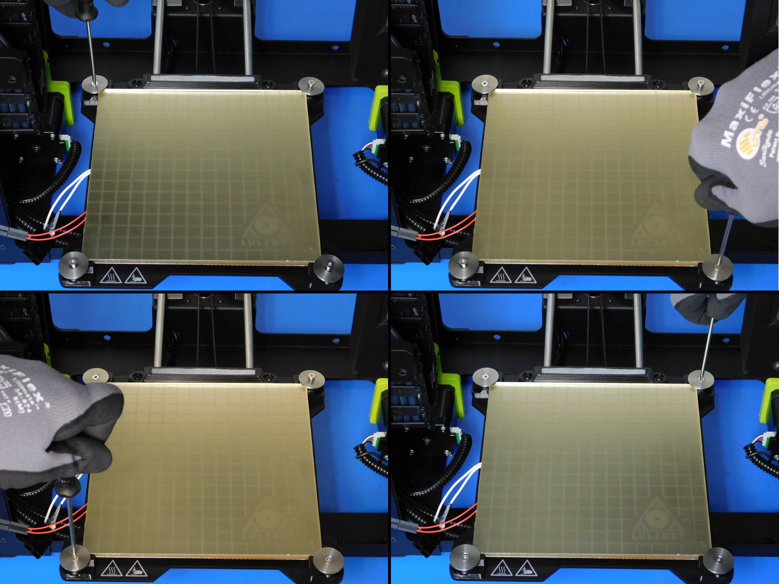
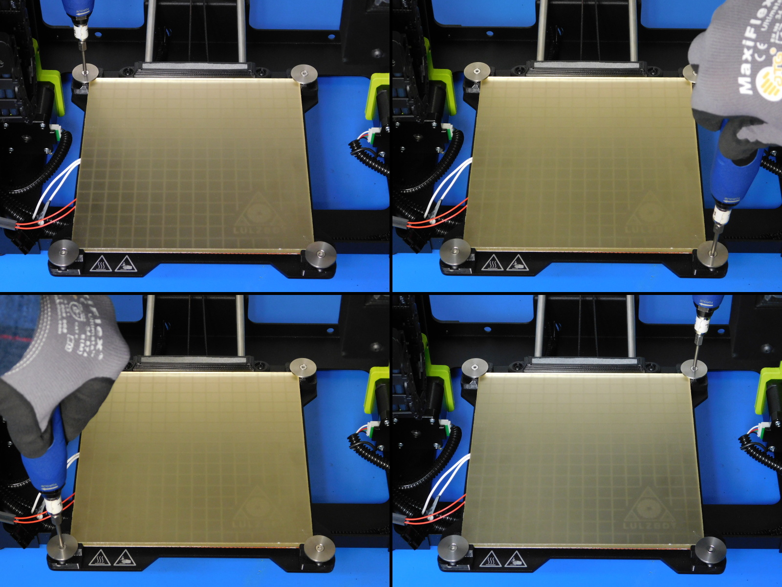
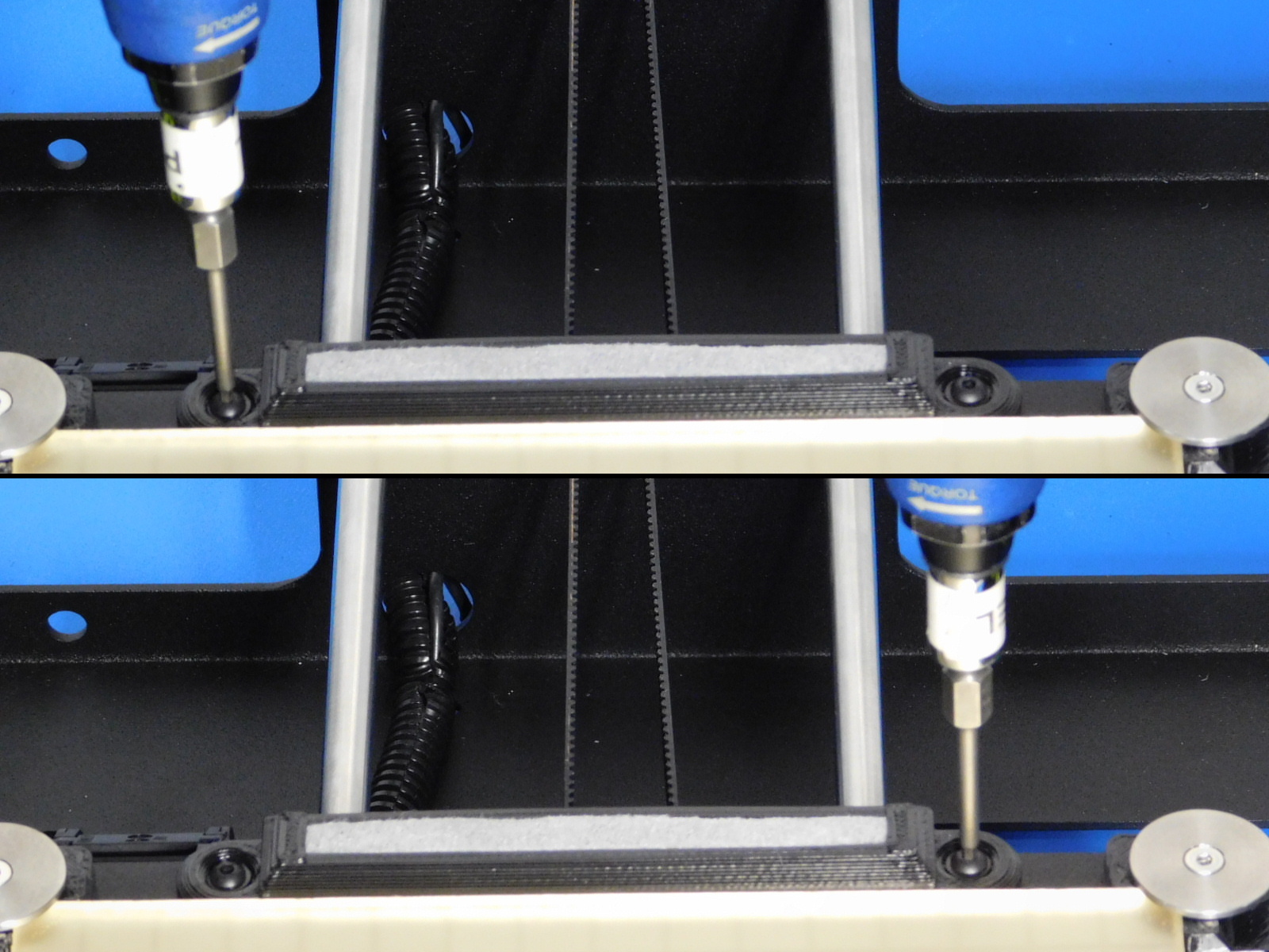
Fasten the heater/glass bed down with four M3x16mm Stainless Steel Flat Head Cap Screws [HD-BT0082] and four Bed Leveling Washers [PP-MP0082].
Torque to 5 inlbs. - washers must sit level against the bed*
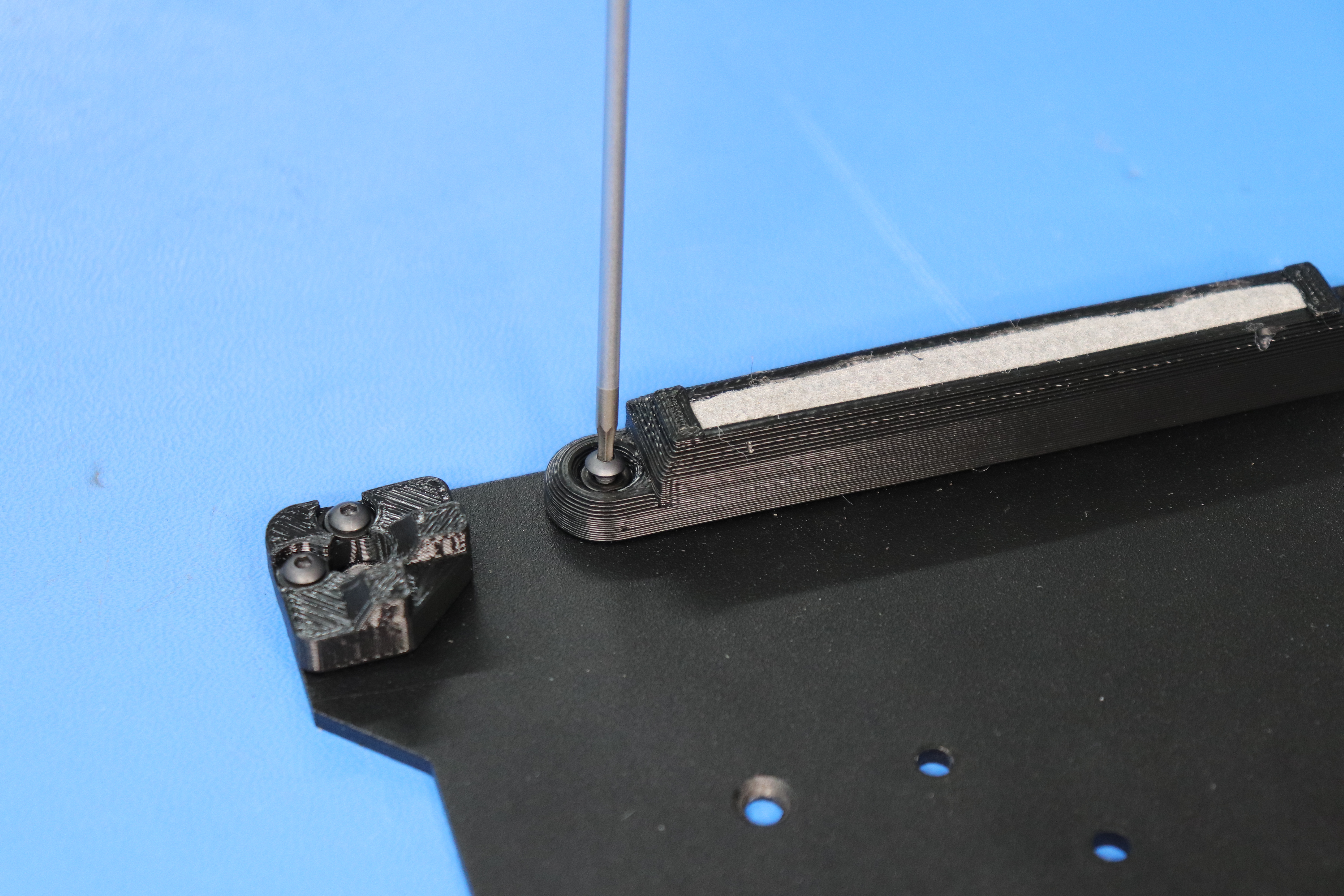
Torque both fasteners securing the Wiper Pad Mount to the Bed Plate to 5in*lbs
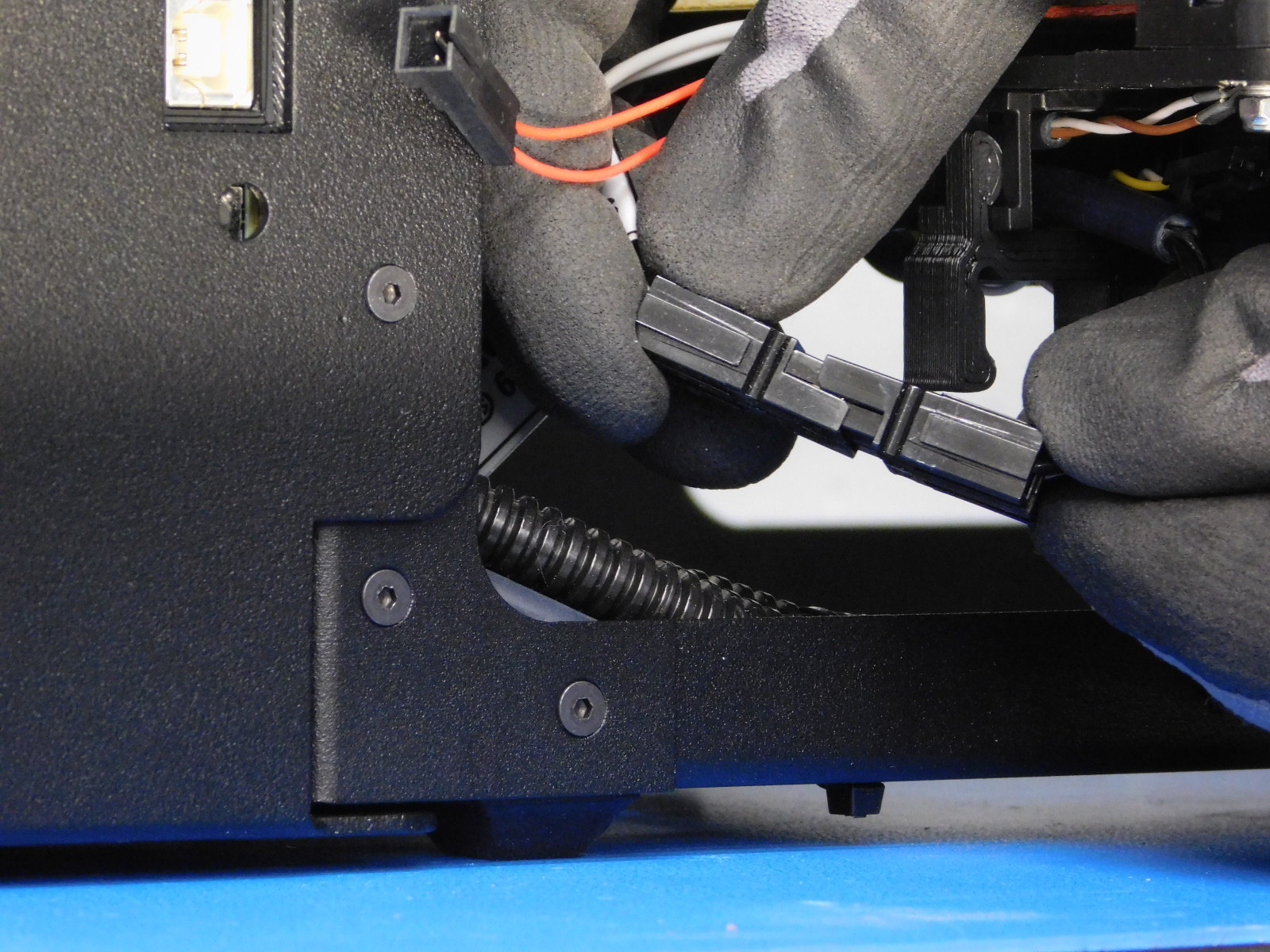
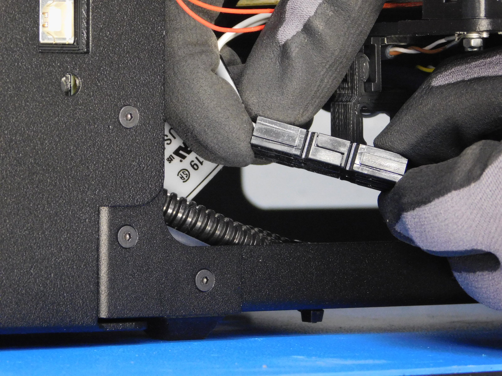
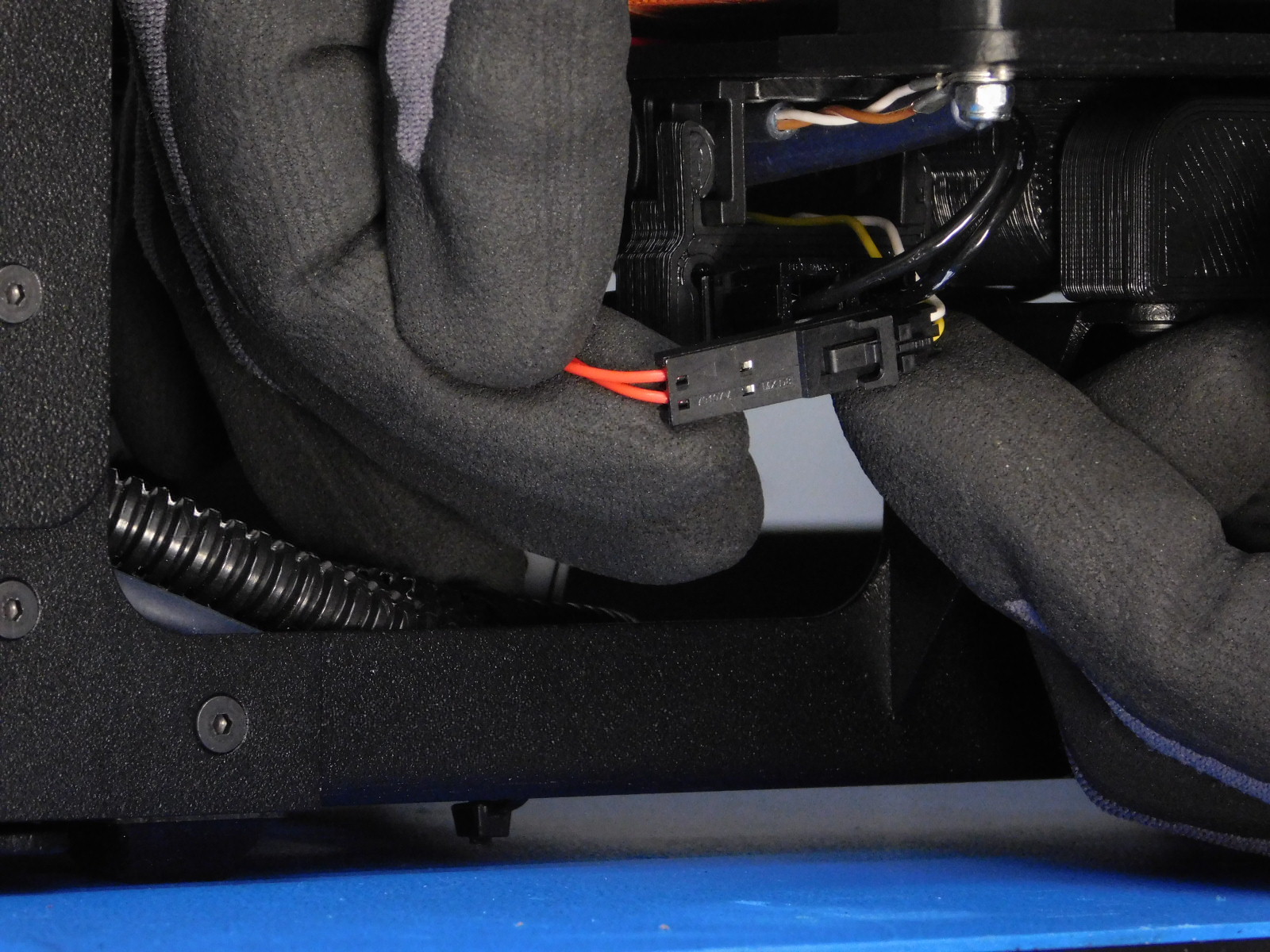
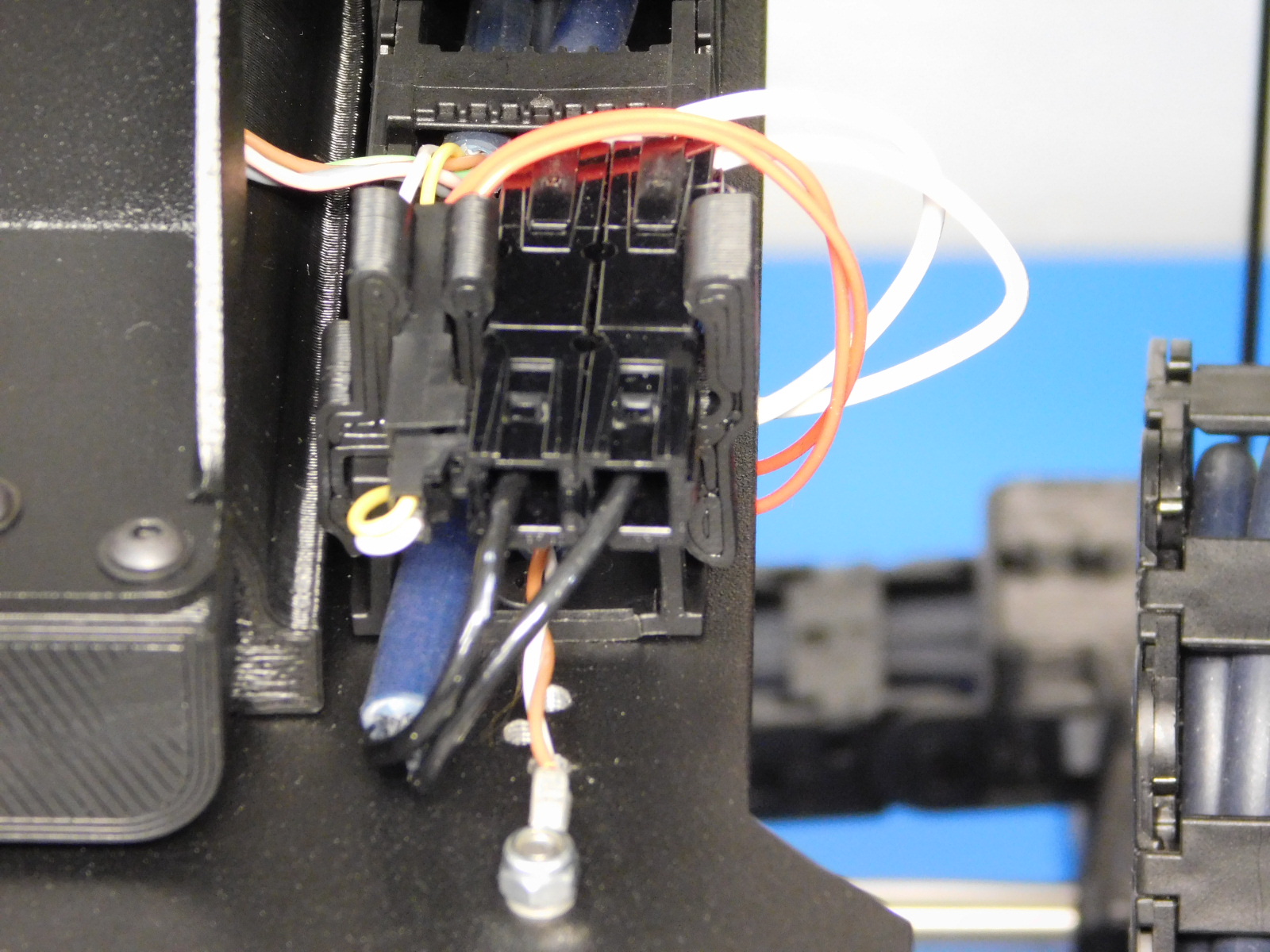
Plug in the bed thermistor and heater cable connectors.
Insert the connectors in the appropriate slots on the Mini Bed Clip [PP-GP0249].
Ensure the thermistor (white and yellow wires) is routed under the bed clip as shown.
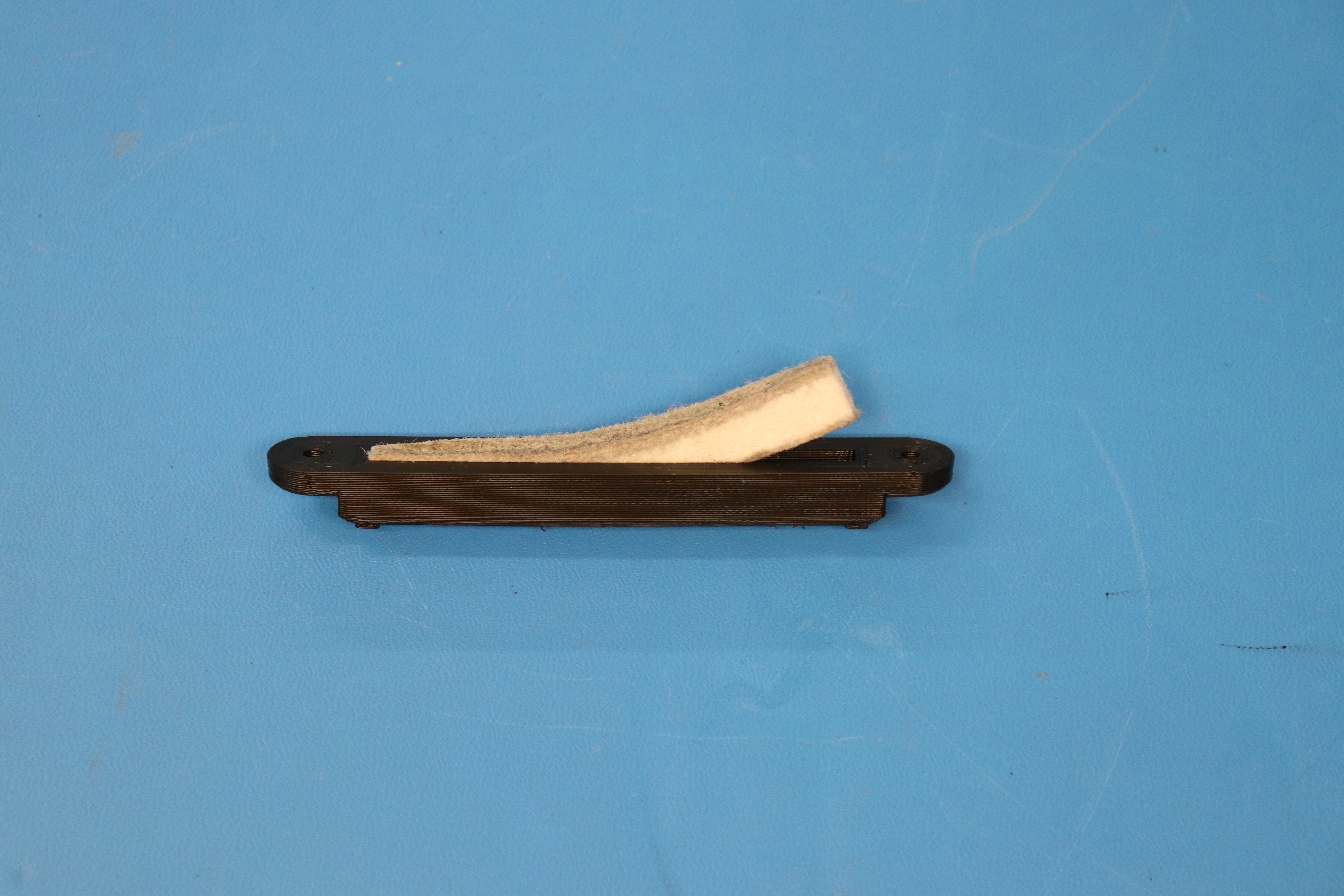
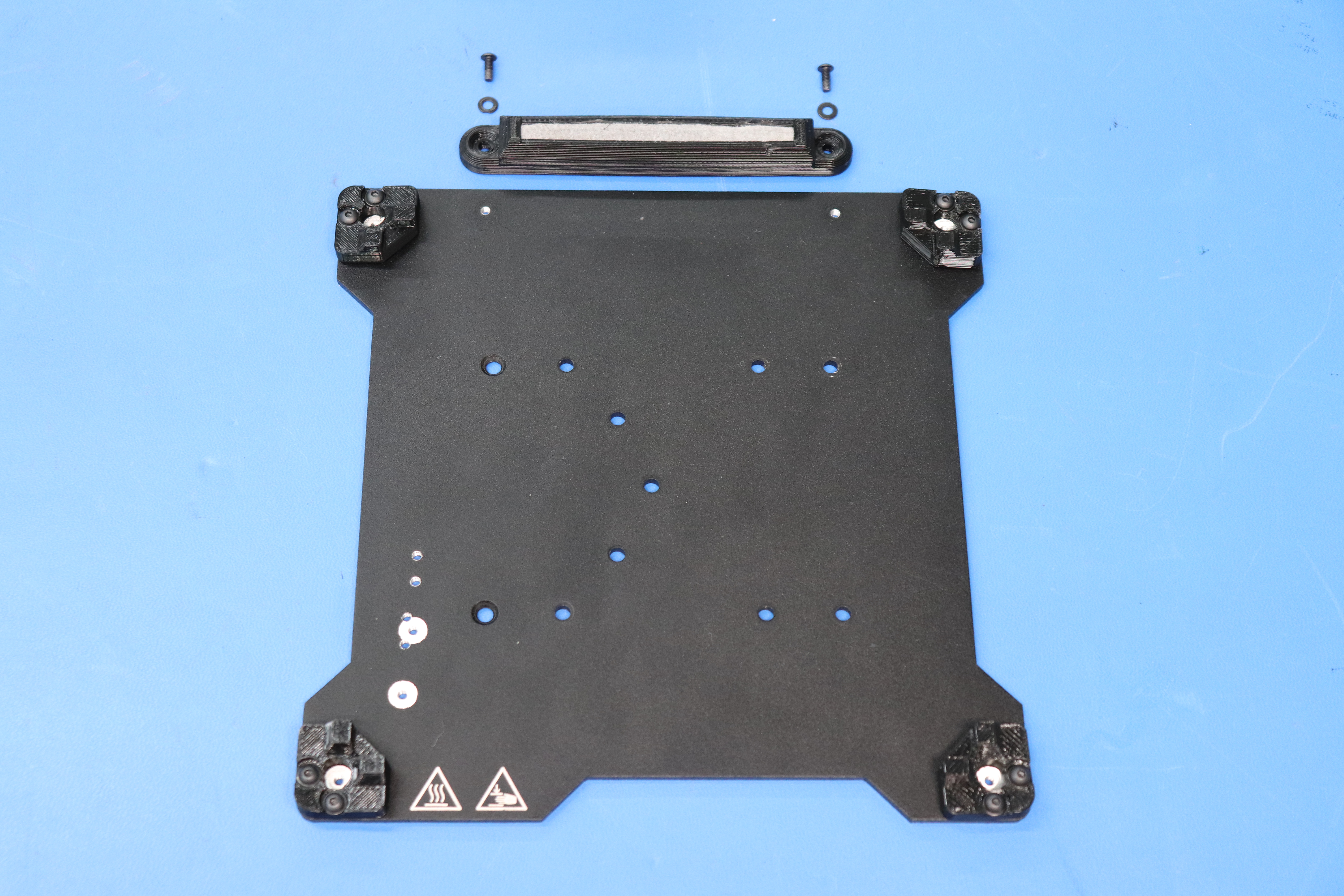
Push the felt wiper pad [AS-PR0023] into the wiper pad mount [PP-GP0231]. Then, attach the wiper pad mount to the bed plate using two M3 x 8 BHCS [HD-BT0137] and two M3 washers [HD-WA0038]. Leave the wiper pad fasteners loose by a little bit so that they do not interfere with the bed installation in calibration.
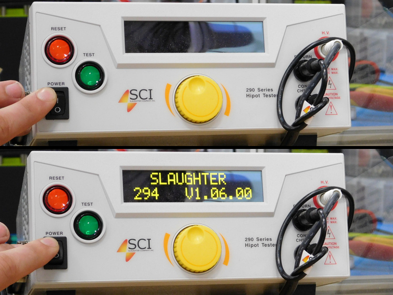
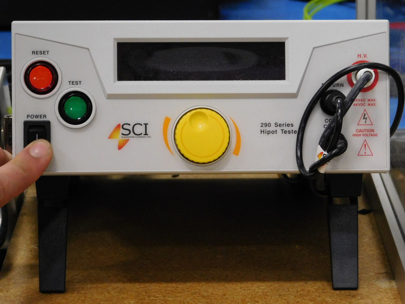
Power on the Hi-Pot testing unit
For North American shipments:
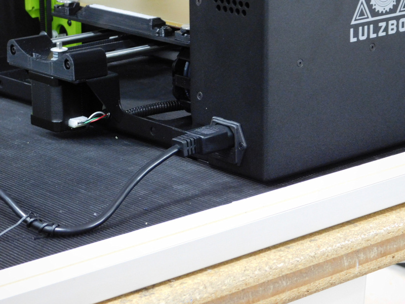
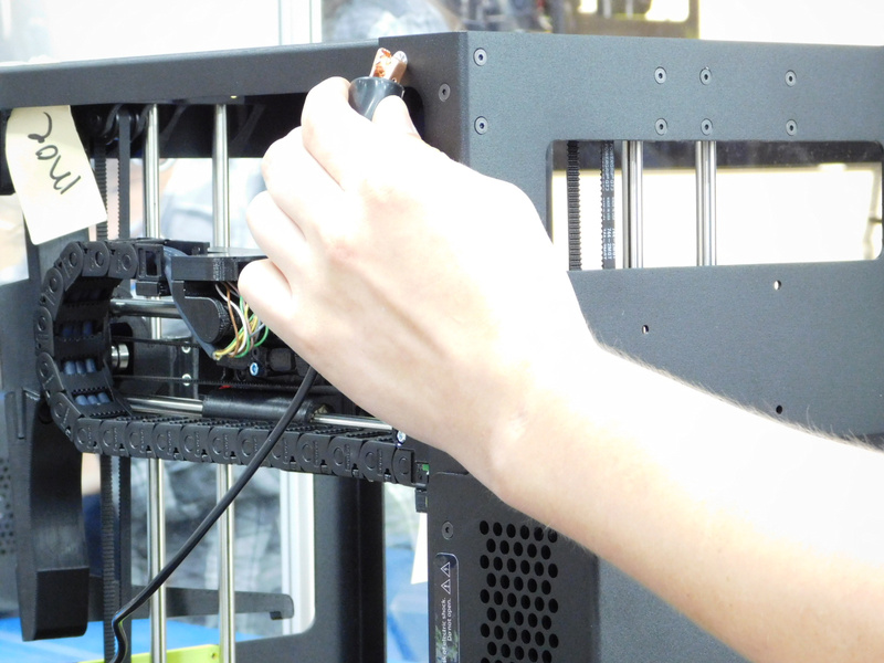
Obtain a North American power cable [EL-CA0030] and connect it to the printer, this will be the cable shipped with the printer.
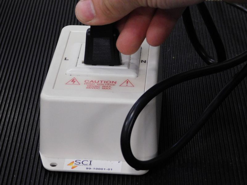
Plug the other end of the cable into the testing units receptacle.
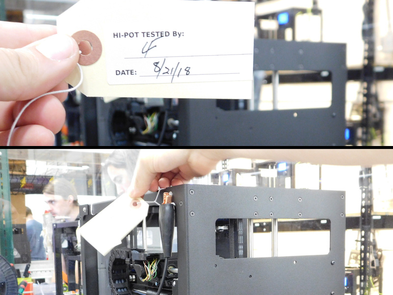
Connect the Hi-Pot testing units gator clip securely to one of the stainless ground screws on the rear of the printers frame
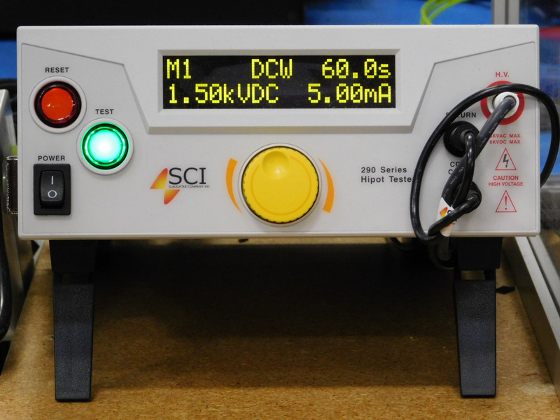
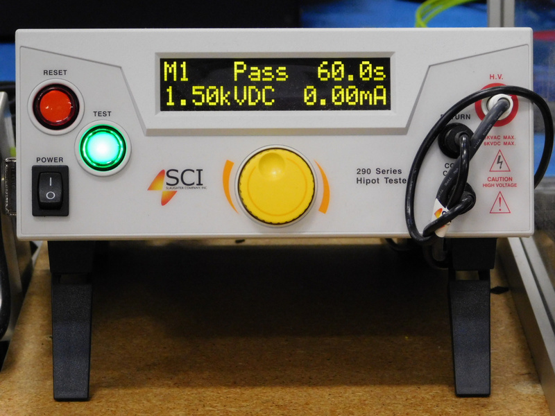
The green light on the Hi-Pot tester should now be illuminated, indicating proper continuity of the ground circuit.
IF THE GREEN LIGHT FAILS TO ILLUMINATE, THE PRINTER HAS FAILED THE TEST
Starting the test:
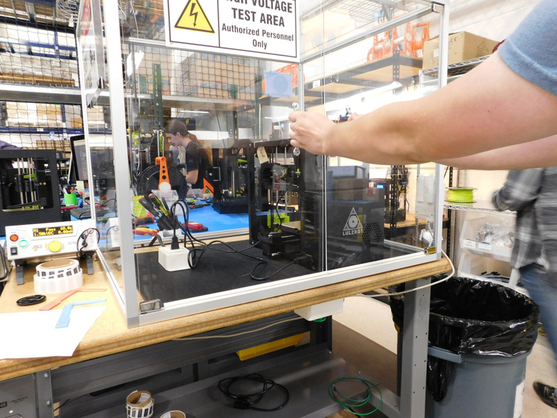
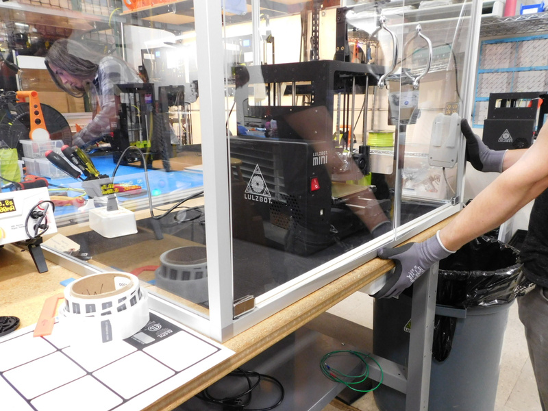
ENSURE THERE IS NO PHYSICAL HUMAN CONTACT WITH THE PRINTER OR HI-POT TESTER
WITH BOTH HANDS, ENGAGE THE INTERLOCK BY PRESSING THE BUTTON TO YOUR LEFT WITH YOUR LEFT HAND AND THE BUTTON TO YOUR RIGHT WITH YOUR RIGHT HAND TO BEGIN THE TEST
STEP AWAY FROM THE UNIT WHILE THE TEST COMPLETES
If the Hi-Pot test unit reports "PASSED" ensure this state is recorded on the QA sheet to be sent with the printer and forward the printer (with the tested cable) to the next available calibrator.
A "FAIL" report from the Hi-Pot tester indicates a problem with the printers power supply or grounding circuit. Refer the machine to MER for proper diagnosis.
For EU/AU/UK shipments:
Use a UK Power Cable [EL-CA0031] for the test. This power cable will be used for the remaining calibration tests and shipped with the printer.
Materials required:
1x- [DC-LB0146] LulzBot Mini 2 Certification Sticker
This sticker is tamper evident, so you only get one chance
Using the certification sticker placement jig provided, carefully line up and apply a Certification Sticker [DC-LB0146] to the rear of the electronics case as pictured.

Tools Needed:
Torque Drivers
Validate all screws on the machine are properly secured.
Start with large screws and then check small screws/setscrews.
Check that all frame screws are tight/properly torqued to 5 in-lbs.
Check that all plastic parts are fastened securely/properly torqued:
Y Assembly:
Y ends – 5 in-lbs
Wiper Pad Holder- 5 in-lbs
Bed Corners - 5 in-lbs
Z axis:
Right and Left Z lowers (except set screws) - 5 in-lbs
Right and Left Z uppers (except set screws) - 5 in-lbs
Z-Belt Clamps - 2inlbs
Z-Lower Left mounting screws are not accessible. Ensure the part is secure to the frame*
X-Carriage/Toolhead:
Extruder Mount- 5 in-lbs
X-Bearing Holder- 3 in-lbs
Fan Mounts- 3 in-lbs
Belt Mount- 5 in-lbs
Frame:
Spool arm hinge bracket to frame- 5 in-lbs
Spool arm support- 8 in-lbs
Spool Arm- 8 in-lbs
Handle- 5 in-lbs
LCD Side Cable Bracket- 5in-lbs
LCD Top Cable Brackets- 3in-lbs
Check that all motors and hardware are mounted securely/properly torqued:
Motors-5 in-lbs
Z-Max Endstop-2 in-lbs
X and Y Belt Clamps-5 in-lbs
Bed washers- 5 in-lbs
Fans- 3 in-lbs
Check that all set screws are tight/properly torqued:
Motor Pulleys- 5 in-lbs
X end setscrews- 2 in-lbs
Z smooth rod setscrews- 3 in-lbs
Y end motor adjustment screws- 5 in-lbs max
Inspect the machine for customer facing cosmetic defects such as:
Scratches or scuffs on the frame sheet metal
Cracks or stress marks in printed parts or the LCD cover
Remove the protective cover from the LCD Display and ensure that it is free of debris and scratches.
Also make sure the back-light of the LCD Display does not appear bowed.
Tools Needed:
Sonic Belt Tensioner
For complete instructions regarding the 508C Sonic Tension Meter use with Mini 2, see THIS OHAI
With the machine off, start by checking that the Y axis moves smoothly and check for play in bearings
Check the belt tension with a sonic belt tensioner. The belt tension should be between 23-27 Newtons.
Slide the Y axis through its full range of motion and check for binding or play. The bearings should fit snugly on the smooth rods and not wiggle. Try wiggling the bed plate, it should not have any play.
Check the X-Axis:
Check the belt tension with a sonic belt tensioner. The belt tension should be between 23-40 Newtons. Slide the X axis through its full range of motion. Again the X carriage should slide smoothly without binding or have any play in the bearings. The bearings should fit snugly on the smooth rods.
Check the Z-Axis:
Check the belt tension with a sonic belt tensioner. The belt tension should be between 35-45 Newtons. Utilize CuraLE or the LCD controller to move axis through its full range of motion. The Z-Axis should move smoothly through the whole range of motion.
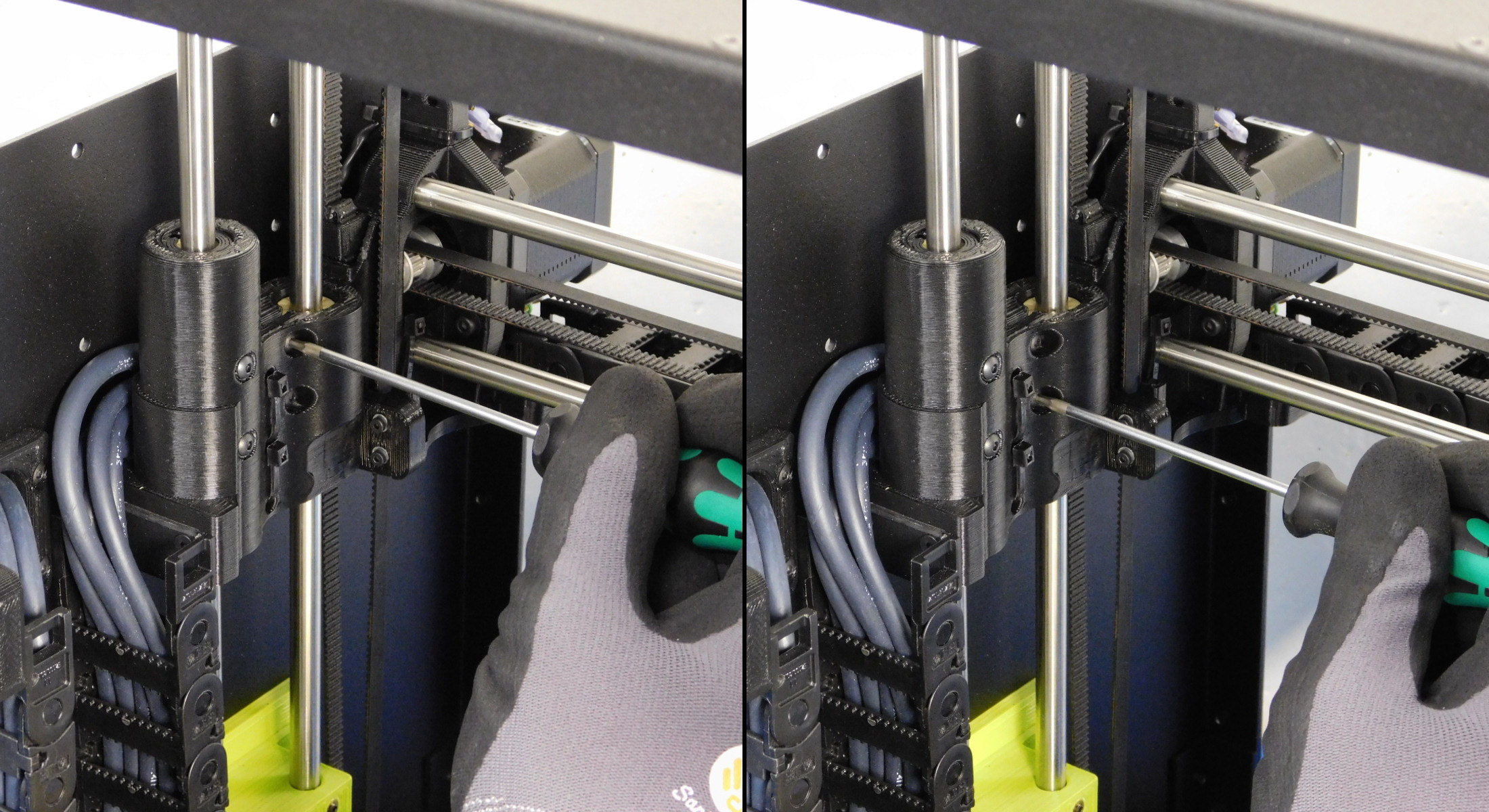
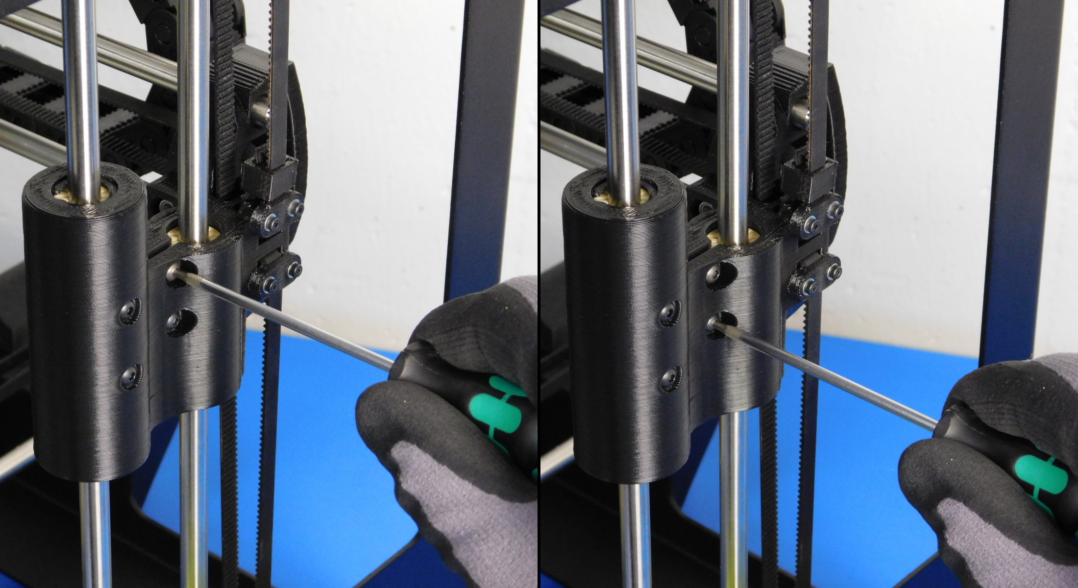
Now we will adjust the Z-Axis compression bushings so that the Z-Axis doesn't fall when the machine is powered on and the steppers are disabled.
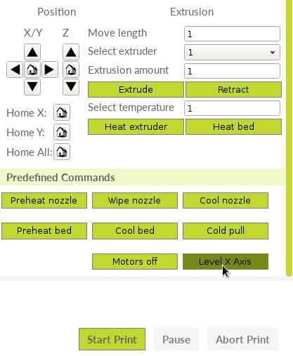
To do so, first level the X-Axis via the Movement menu of the LCD or the button located towards the bottom of CuraLE's printer control panel.
Then via the LCD's Movement menu, select "Disable steppers." This will turn the motors off so watch the Z-axis when triggering to see if any downward movement occurs.
If any downward movement is observed, tighten the compression hardware on that X-End 1/4th of a turn on each screw before repeating the test.
Continue to repeat this process ONLY until the Z-Axis doesn't fall under its own weight. If "disable steppers" is selected and no movement is observed, no action is necessary.
Turn on the printer with the USB plugged into the printer and the CPU.
Open the latest edition of Cura Lulzbot Edition
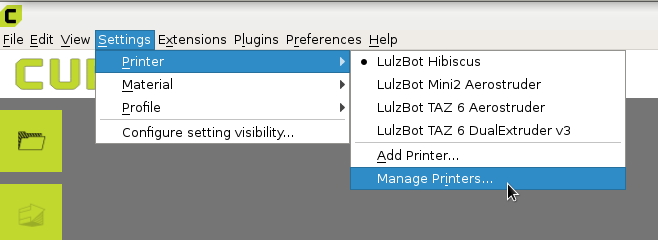
On the top left, click on the “Settings” drop down menu and navigate to Printer > Manage Printers...
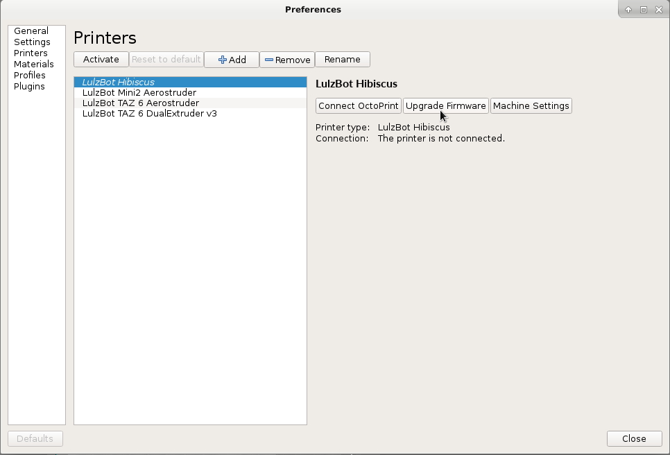
In the dialogue that appears make sure Lulzbot Mini 2 is selected on the left.
Select "Upgrade Firmware"
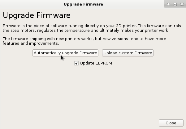
In the dialogue that now appears, select "Automatically upgrade firmware"
The software will now automatically install the firmware.
Use the mini firmware check script in the repo to ensure the correct firmware was flashed. There should be a launcher icon on the desktop of your calibration workstation. Otherwise, the script can be found here: https://code.alephobjects.com/diffusion/UC/browse/master/firmware_validation/mini2_firmware_check.sh
You can execute the script by opening a terminal and running ./mini2_firmware_check.sh
With the machine still on and connected to Cura Lulzbot Edition;
First auto home the printer to verify the X-Min, Y-Max, and Z-Max endstops/bumpstops are functional.
Next level the X-Axis via the button found at the bottom right of CuraLE Manual Control Panel. Watch this closely to ensure both X-End printed parts make contact with both Z-Lower printed parts to achieve proper level. If one side fails to reach bottom before the X-Axis Leveling g-code completes, this indicates Z-Binding. Proceed to Z-Binding Troubleshooting.
Move the Z-Axis up and down through the full range of motion. The Z-Axis should move smoothly and not have any binding.
Enter the command M119 in the Cura Lulzbot Edition console to check the endstop status. It should report all Endstops "OPEN"
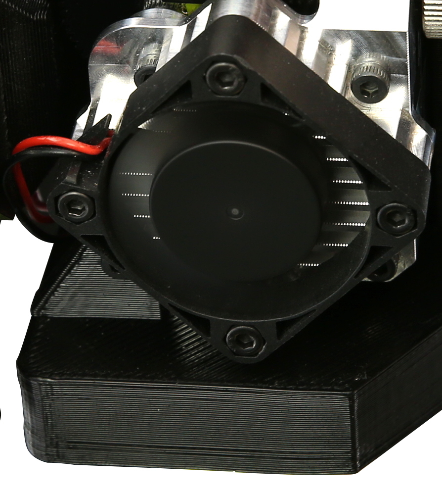
Verify that the Heatsink Fan is spinning any time the machine is powered on.
Using CuraLE or the printer's LCD, heat the extruder to 200 Celsius. By hand, grab and pull the filament protruding from the top of the idler while spinning the top of the extruders large gear away from you to remove the filament from the extruder.
Without filament loaded, spin the spur gear of the extruder and verify it can be rotated smoothly without binding.
Visually check the alignment of the two gears of the extruder, the two surfaces should be flush with each other.
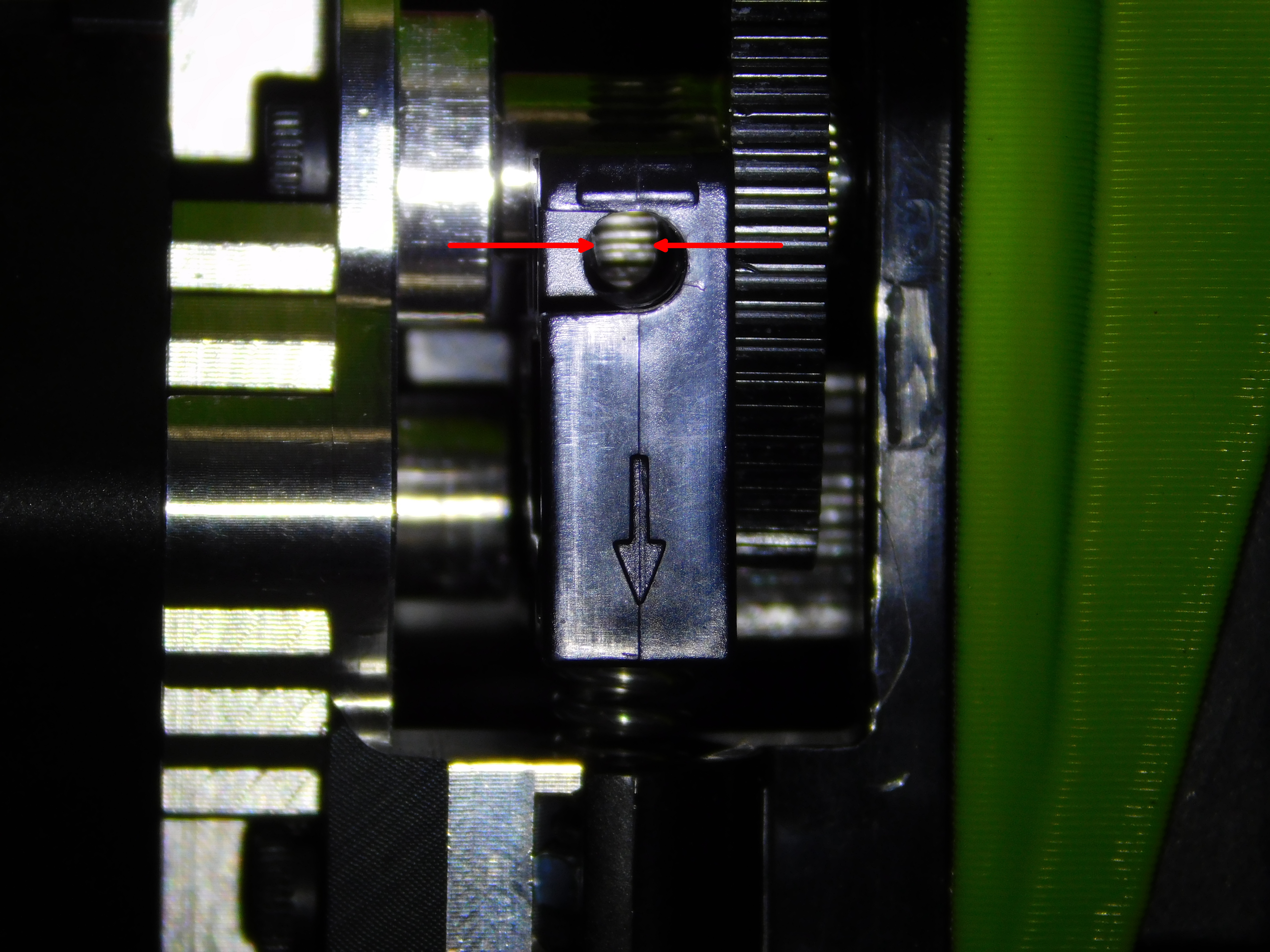
Looking directly down from the top of the extruder, through the Idler lever's filament path, ensure that the hobbing extends to both left & right outer diameters of the filament path.
As long as there is hobbing covering the width of the filament path when viewed from the top of the idler, the tool head is good to use.
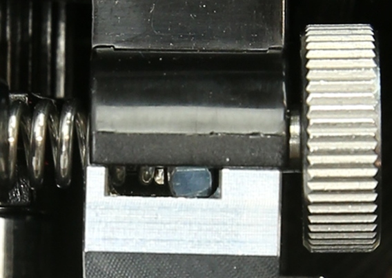
Set Idler tension by turning the Idler Adjustment Thumb screw counter-clockwise until the spring end at the nut is at about the halfway point of the viewing window; as pictured.
In the Cura Lulzbot Edition console, enter the command M106 S255 to turn the part cooling fan on to full speed. Let it run momentarily to verify proper function.
Enter M107 in the console to turn the fan off.
Materials Needed:
3m- PolyLite PLA LulzBot Green Filament Sample (RM-PL0118)
SD card
Tools Needed:
Micrometer
With the printer still connected to Cura Lulzbot Edition;
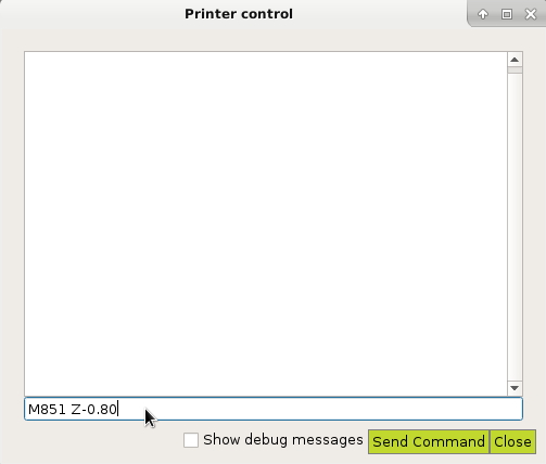
Enter the command “M851 Z-0.80.” This sets the Z offset to -0.8mm to ensure we don't crash the bed on the first attempt.
Now enter the command “M500” to save this setting.
This can also be accomplished through the LCD Controller if desired.
Insert the pre-loaded SD card into the slot on the left of the LCD Controller.
Run the dimensional accuracy test titled "PLA_HS_QuickCircle.gcode" this gcode can be used for offset calibration as well as verifying dimensional accuracy.
Watch the skirt print and stop the print once the skirt has finished. Measure the skirt height with a micrometer. The skirt should give a 0.30mm-0.5mm bead height.
NOTE: When starting the octopus test print watch the printer perform its wipe function to be sure it is wiping the nozzle on the wiper pad and not dragging the nozzle through the wiper pad mount.
From the SD card, run the burnin.gcode in its entirety
- This will run the printer through its full range of motion multiple times to ensure all parts are “broken in.” For instance some tight bearings will loosen up a bit after burn in.
During burn in, keep an eye/ear out for any sounds or motions that are atypical; specifically vibration of the axis during movement may indicate a linear bushing that has too much play.
From the SD card, run the dimensional accuracy test titled "PLA_HS_QuickCircle.gcode"
Let the print fully finish and inspect for issues.
Check for “flatlining” which occurs when printing a circle or round edge, part of the circle will be a straight edge instead of a smooth arc. This is usually caused by bushings binding on the smooth rods and not sliding smoothly.
On the "cake tower" there is a 10mm circle. Measure the 10 mm circle with a pair of calipers. If any measurement is obtained above 10.20mm or below 9.80mm, fix the machine and try again.
An axis that is too stiff may cause the stepper motor to skip steps, watch for layer shifts in the X/Y Axis
Check for any feature that is inconsistent from "normal" prints
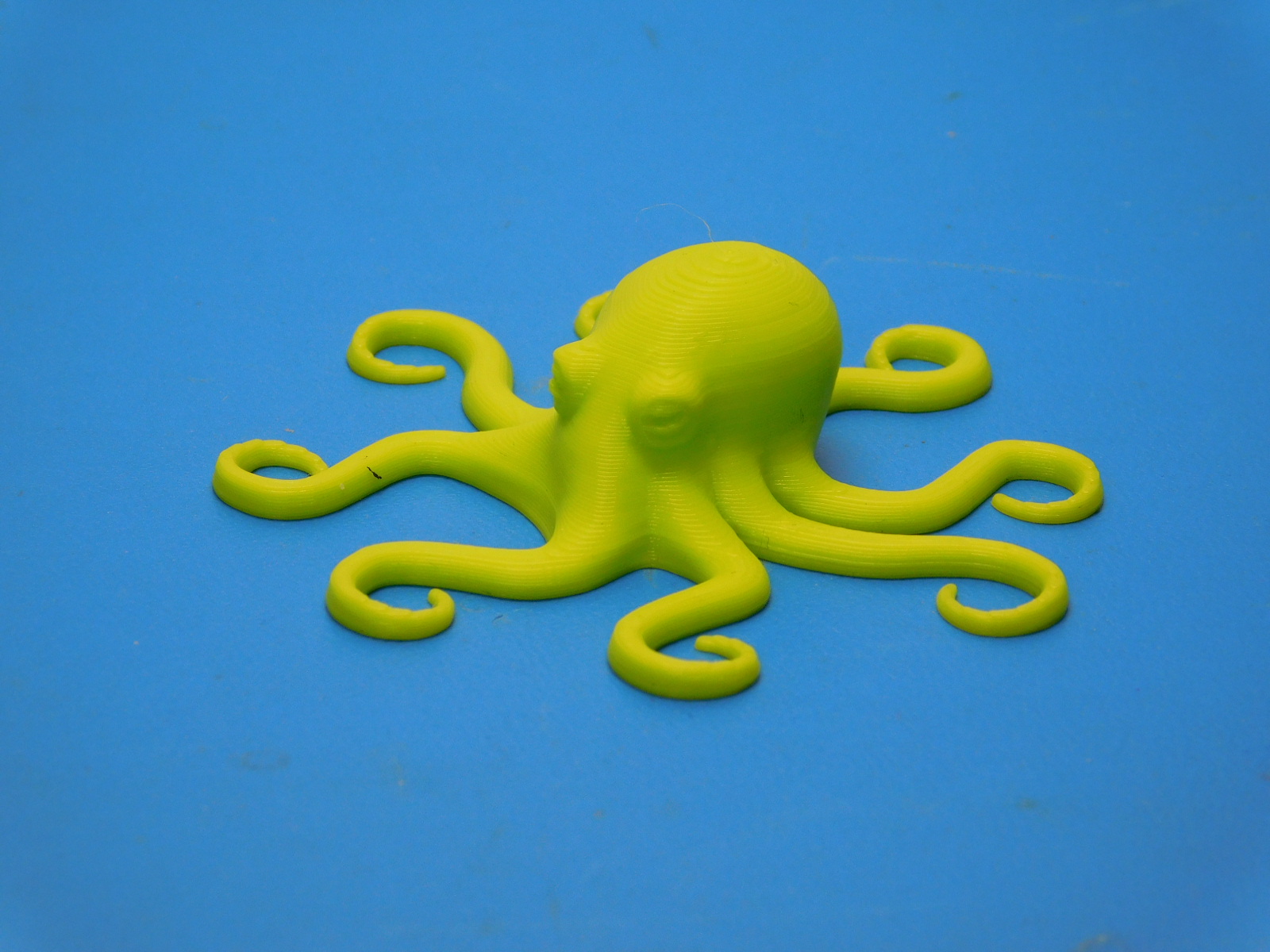
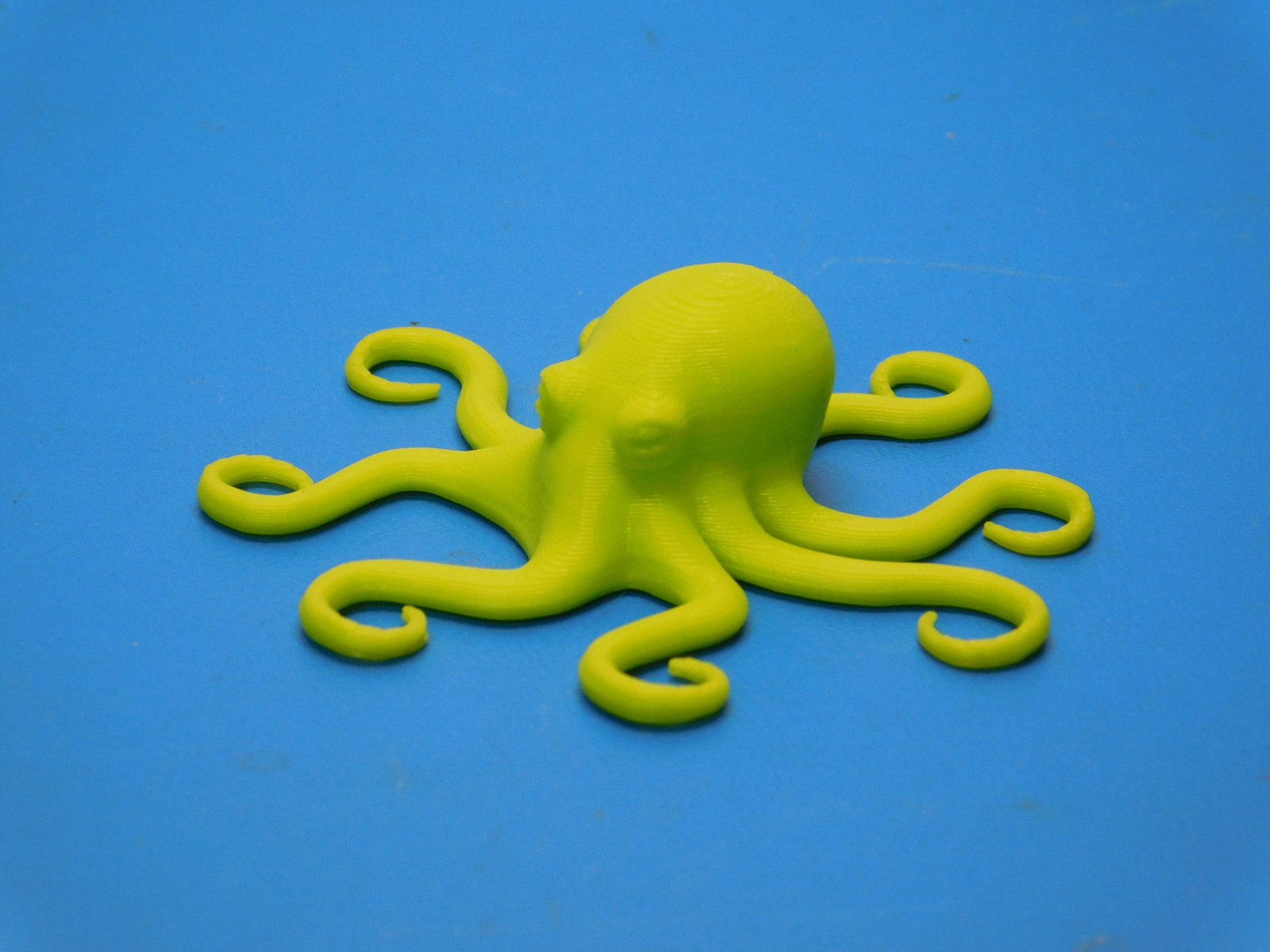
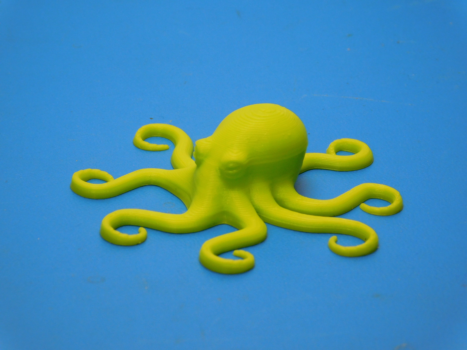
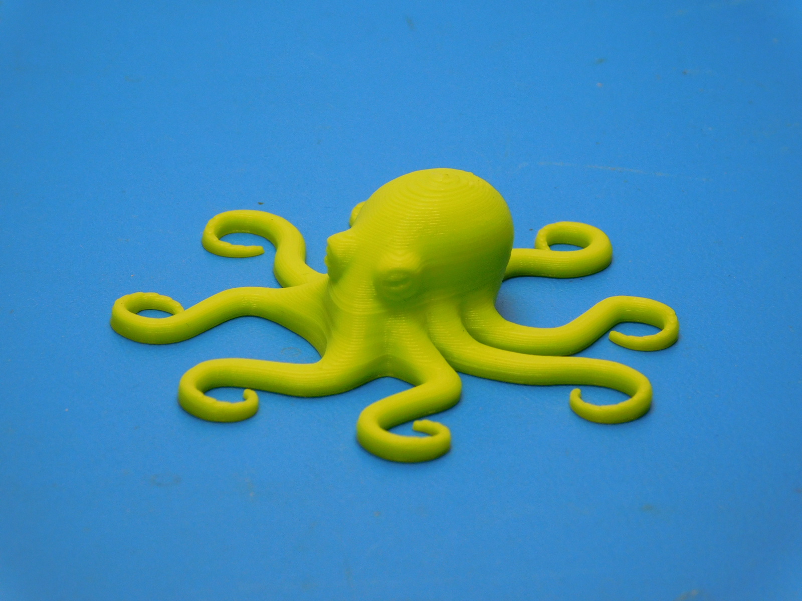
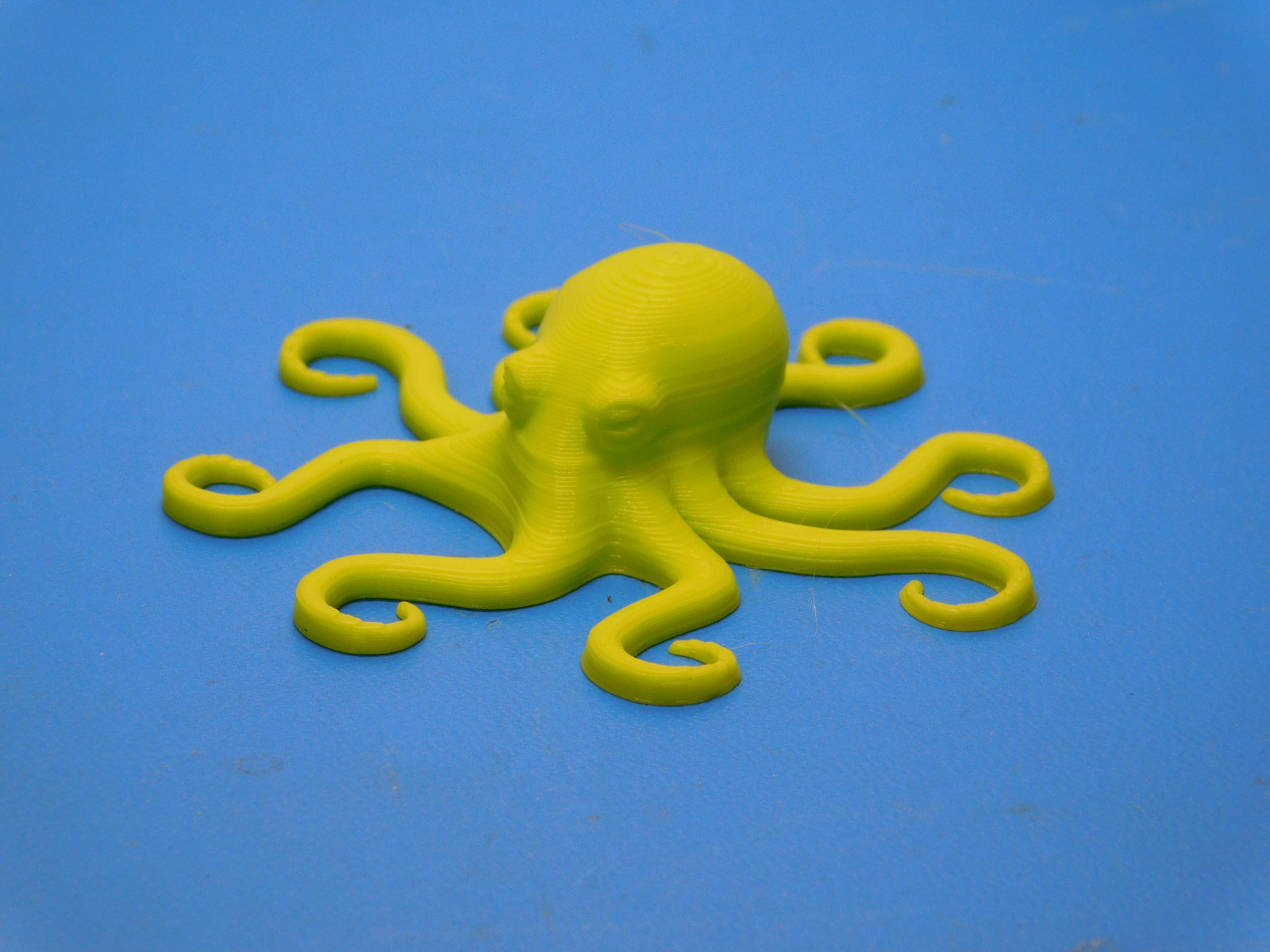
If the QuickCircle is good, proceed to printing the calibration octopus titled "v2Aero_Octopus_Calibration_PLA_v1.5.gcode"
If the octopus print doesn't have any issues, apply blue thread locker to all pulley set screws and place the machine, QA Record, Power/USB Cables, and the successful test print on the boxing queue.
See pictures for examples of passable octopi. Minor layer defects are passable so long as they are only on one side and do not exhibit skipped steps or do not exceed .05mm surface condition variance.

Put the serial number label sticker in the center of the serial number label sticker shaped spot on the certification sticker. Make sure it is straight and centered.