Open HardwareAssembly Instructions
Guides for installation and assembly of the LulzBot line of products made by FAME 3D LLC.
Guides for installation and assembly of the LulzBot line of products made by FAME 3D LLC.
The LulzBot Mini Graphical LCD Controller is compatible with the latest generation of LulzBot Mini 3D Printers with a serial number of KT-PR0035NA-7500 or higher. Users with LulzBot Mini 3D Printers below serial range KT-PR0035NA-7500 need to visually inspect the Mini RAMBo control electronics for compatibility using this guide.
The current generation and some early versions of the LulzBot Mini control electronics have the required Graphical LCD Controller headers installed on the Mini RAMBo. An updated Mini RAMBo is available for those users needing to upgrade.

2 mm hex key or driver included with your LulzBot Mini
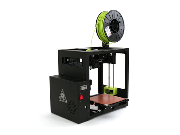
LulzBot Mini Desktop 3D Printer
3A
If a filament reel is on the printer, disconnect filament and remove the reel.
3B
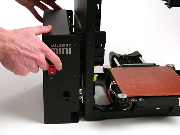
Power off printer.
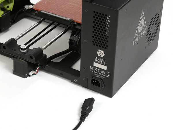
3C
Disconnect printer.
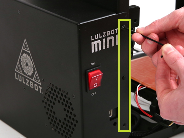
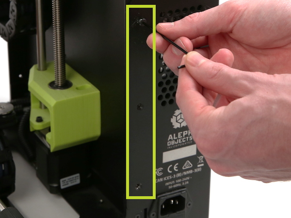
4A
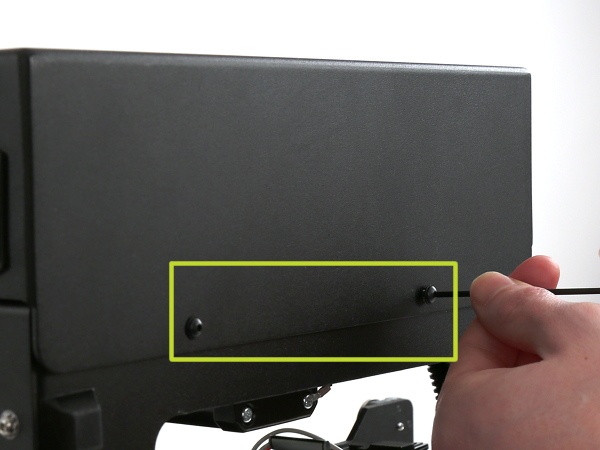
On the LulzBot Mini v1.03 and earlier versions, locate and remove 3 M3x6 flat head cap screw (FHCS) bolts on the front of the printer, and another 3 M3x6 flat head cap screw (FHCS) bolts on the rear of the printer.
On the LulzBot Mini v1.04, locate and remove 3 M3x6 flat head cap screw (FHCS) bolts on the front of the printer, another 3 M3x6 on the rear of the printer, and 2 M3x12 button head cap screw (BHCS) bolts on the bottom of the printer.
4B
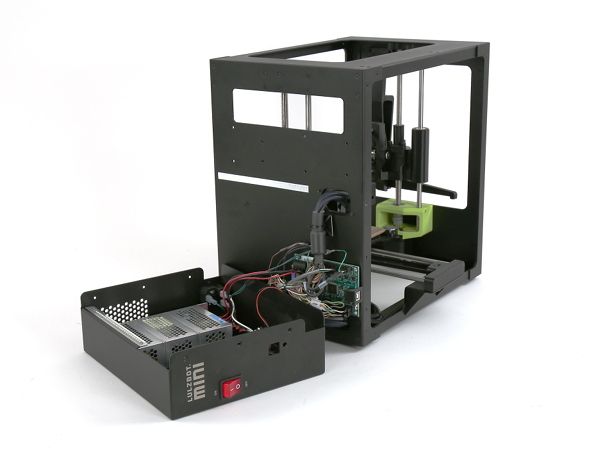
Some wires (power supply and fan) go from case-mounted components to frame-mounted components. Remove case slowly to avoid unplugging them accidentally. However, if a wire becomes disconnected, please refer to the RAMBo and Cable Tie Down Guide for detailed instructions on reconnecting.
4C
Carefully place cover on its side next to the printer, with all wires still connected.

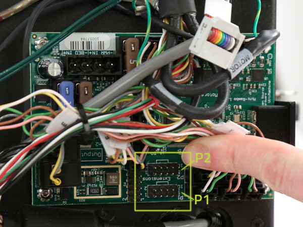
5A
Inspect RAMBo to see if you have P1 and P2 extensions on the RAMBo that will allow you to plug the LCD harness connectors in (see image).
5B
If you have verified that you have the proper connections, and you'd like to install a Mini GLCD, you can proceed to the Mini GLCD install guide.
If you do not have the proper connections, your printer will not be able to accommodate an LCD display without upgrading the RAMBo.
Once you have acquired a new Mini RAMBo v1.3a, follow these removal steps before referring to the appropriate Mini RAMBo Install Guide below:
6A
Before removing the currently installed Mini RAMBo, take a picture of the wires in order to document the colors and connections. Label each wire to simplify reconnecting later.
6B
Double check power is off and unplugged, and then carefully remove all wires from the RAMBo.
6C
Using a 2 mm hex driver, remove the 4 stainless steel M3 x 8 mm button head cap screws from the corners of the board that keep the RAMBo in place.
6D
Depending on if your LulzBot Mini 3D Printer is version 1.04 or 1.03, refer to the appropriate Mini RAMBo install guide below for more connection details:
v1.03: below serial number KT-PR0035NA-7500
v1.04: serial number KT-PR0035NA-7500 and higher

7A
Slide control box cover back on.
7B
On the LulzBot Mini v1.03 and earlier versions, reattach control box cover by screwing back in the 3 M3x6 FHCS bolts on the front of the printer, and another 3 M3x6 FHCS bolts on the rear of the printer.
On the LulzBot Mini v1.04, reattach control box cover by screwing back in the 3 M3x6 FHCS bolts on the front of the printer, another 3 M3x6 FHCS bolts on the rear of the printer, and 2 M3x12 BHCS bolts on the bottom of the printer.


Well done! You've now identified the connections available on your Mini RAMBo. If the proper connections have been verified, proceed to the Mini Graphical LCD Controller installation guide.
If you've just finished upgrading and installing your Mini RAMBo, be sure to update to the latest firmware as well before proceeding to the Mini Graphical LCD Controller installation mentioned above.