Open HardwareAssembly Instructions
Guides for installation and assembly of the LulzBot line of products made by FAME 3D LLC.
Guides for installation and assembly of the LulzBot line of products made by FAME 3D LLC.
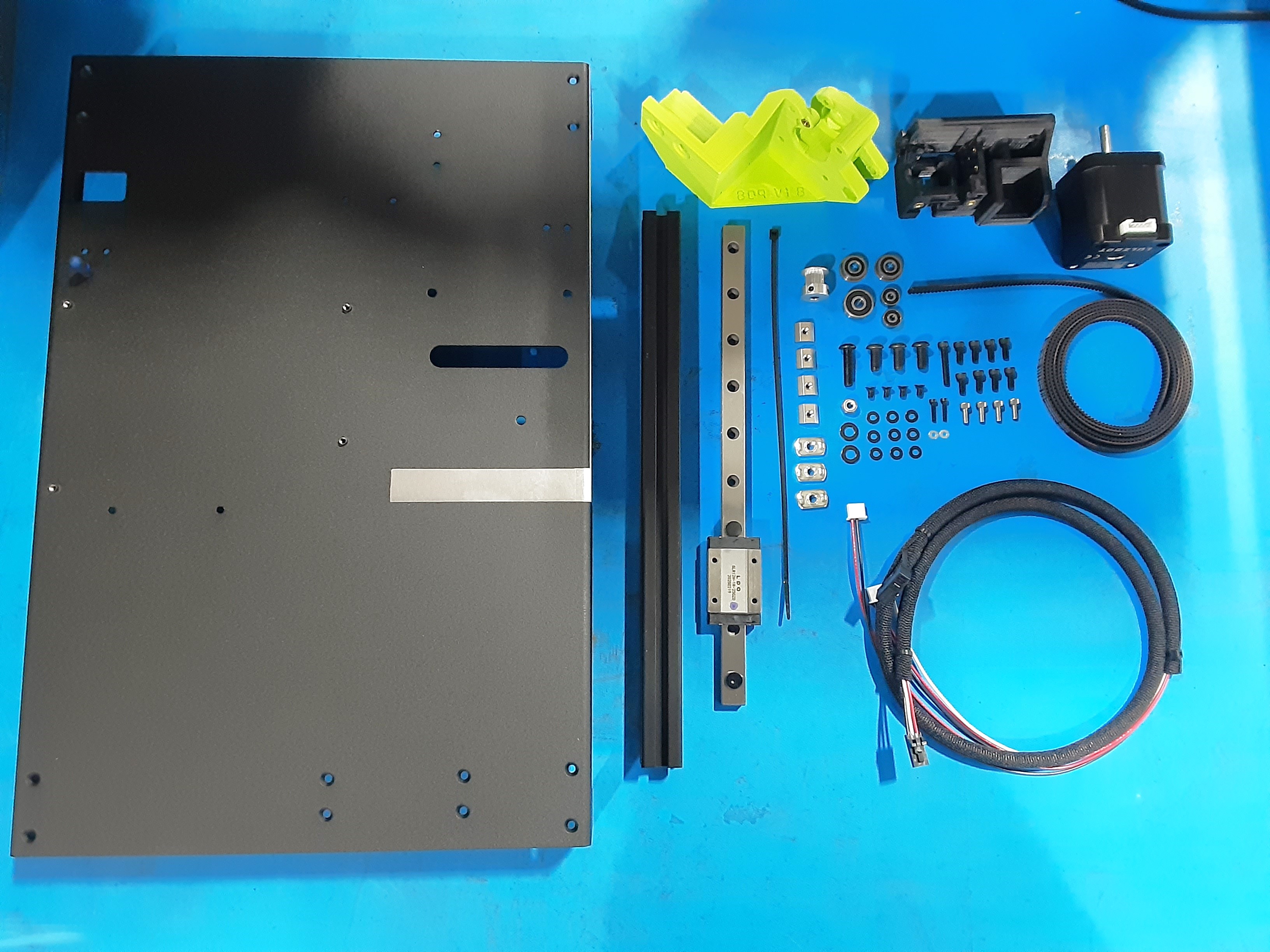
1x [EL-HR0214] Mini3, Z End Stop Harness
1x [EL-MT0068] NEMA 17 Stepper Motor, LDO
1485mm [HD-BL0037] Single Sided Neoprene Open Loop Belt - 6mm wide, 2mm tooth style
1x [HD-BT0007] M3 x 20 Bolt, SHCS Black-Oxide
2x [HD-BT0107] Metric Class 12.9 SHCS Alloy Steel Black, M2 x 10mm Length
4x [HD-BT0128] M3 x 6mm FHCS Black-Oxide
8x [HD-BT0157] Class 12.9 Alloy Steel Black-Oxide SHCS, M3 x 8mm Length
3x [HD-BT0158] Class 10.9 Steel BHCS, M5 x 12mm Length, .8 mm Pitch
4x [HD-BT0170] M3-0.5 X 8MM Length 2.5 SHCS Stainless Steel
1x [HD-BT0272] M5 x 20mm BHCS, Black-Oxide
2x [HD-BU0035] Flanged Bearing 695-2RS
1x [HD-EX0102] T-Slot Aluminum Frame TPW, Extrusion 20mm x 20mm x 280mm
1x [HD-MS0058] Wire Tie, 8" Black, pk 1000
1x [HD-MS0411] 625-2RS Premium Two Side Rubber Sealed Bearing ABEC3
2x [HD-MS0470] Two Side Rubber Seal Bearing, 623-2RS, ABEC1 grade
1x [HD-MS0625] 16T "D" Key Pulley Rev 1.0 With Set Screws
4x [HD-NT0005] Slide in T-nut for Aluminum Frame M3
3x [HD-NT0053] T-Slot Slide in T-nuts for Aluminum Frame, M5
1x [HD-NT0057] 18-8 Stainless Steel Nylon-Insert Locknut M5 x 0.8mm Thread
1x [HD-RD0051] Mini3, Linear Rail, 250mm, single truck
2x [HD-WA0012] Steel Flat Washer, DIN 125 Zinc-Plated Class 4, M2 Size, 5mm OD
9x [HD-WA0038] Black-Oxide 18-8 Steel Flat Washer, M3 Screw Size, 3.2mm ID, 7.0mm OD
2x [HD-WA0040] Black-Oxide 18-8 Stainless Steel Washer, M5 Size, 5.3mm ID, 10.0mm OD
1x [PP-FP0240] Mini3, Left-Side, 12AWG Aluminum Rev 0-5
1x [PP-GP0809] Mini3, Z Lower Left, ABS-GRN
1x [PP-GP0827] Mini3, Z Upper Left, ABS-BLK
Motor Assembly
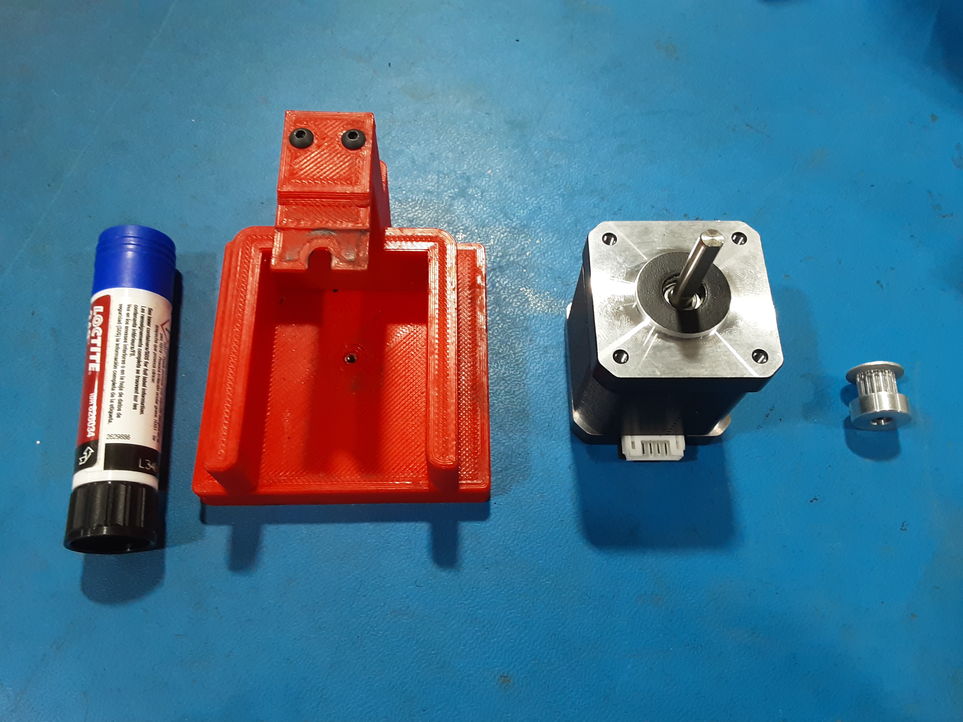
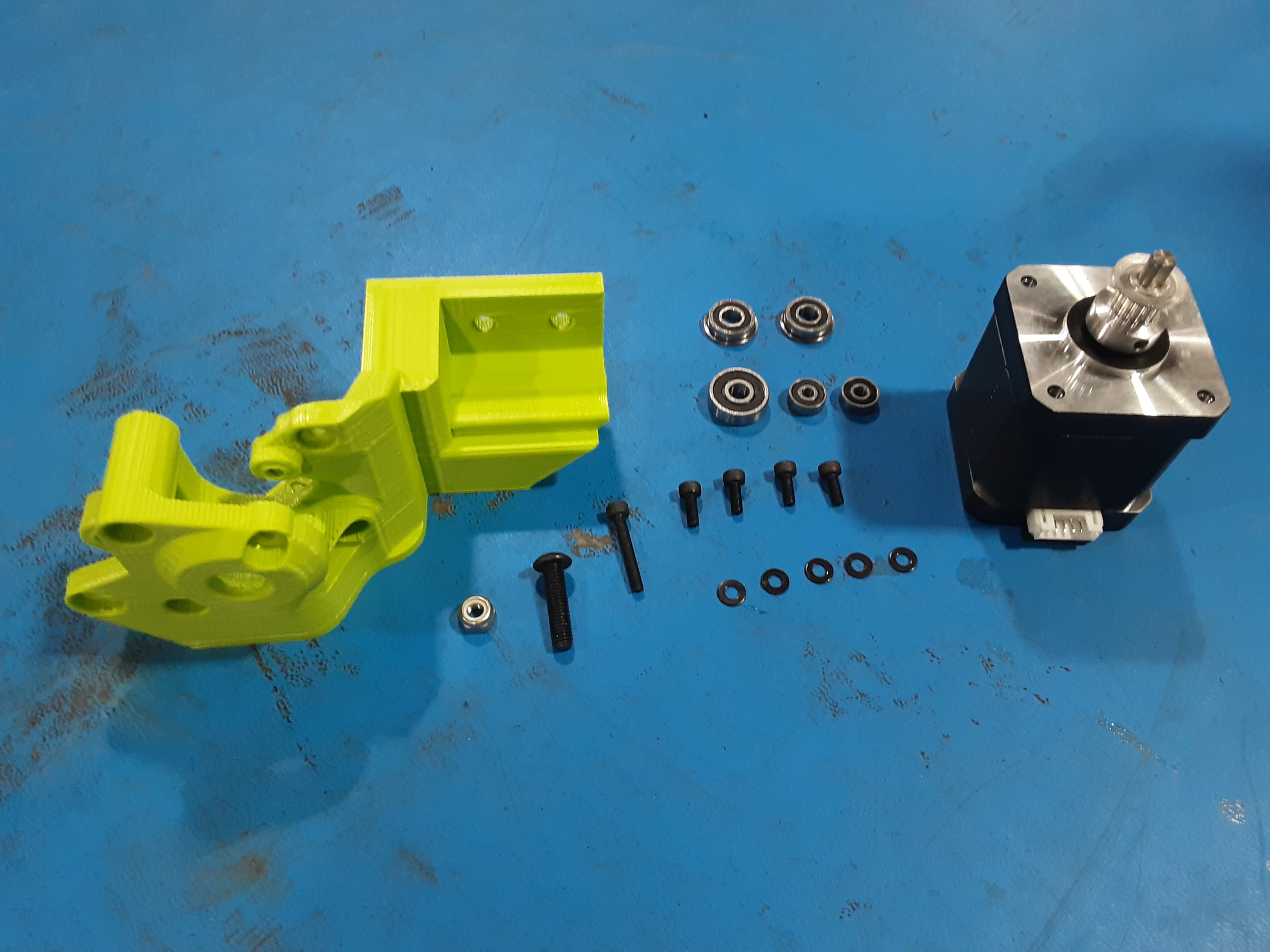
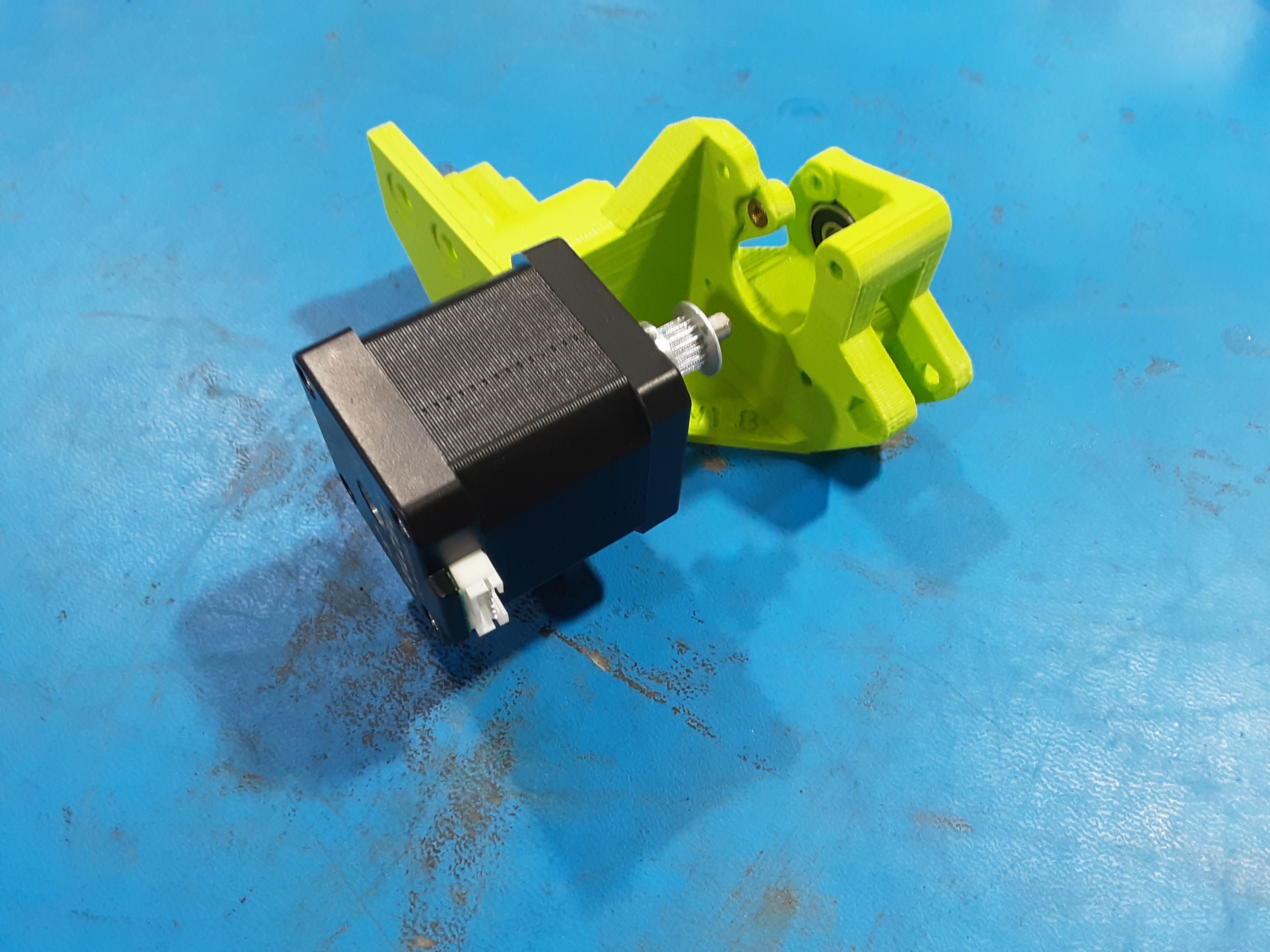
2A )Grab EL-MT0068 x1, HD-MS0625 x1, blue loctite, and the motor jig.
2B) Remove the set screws from HD-MS0625.
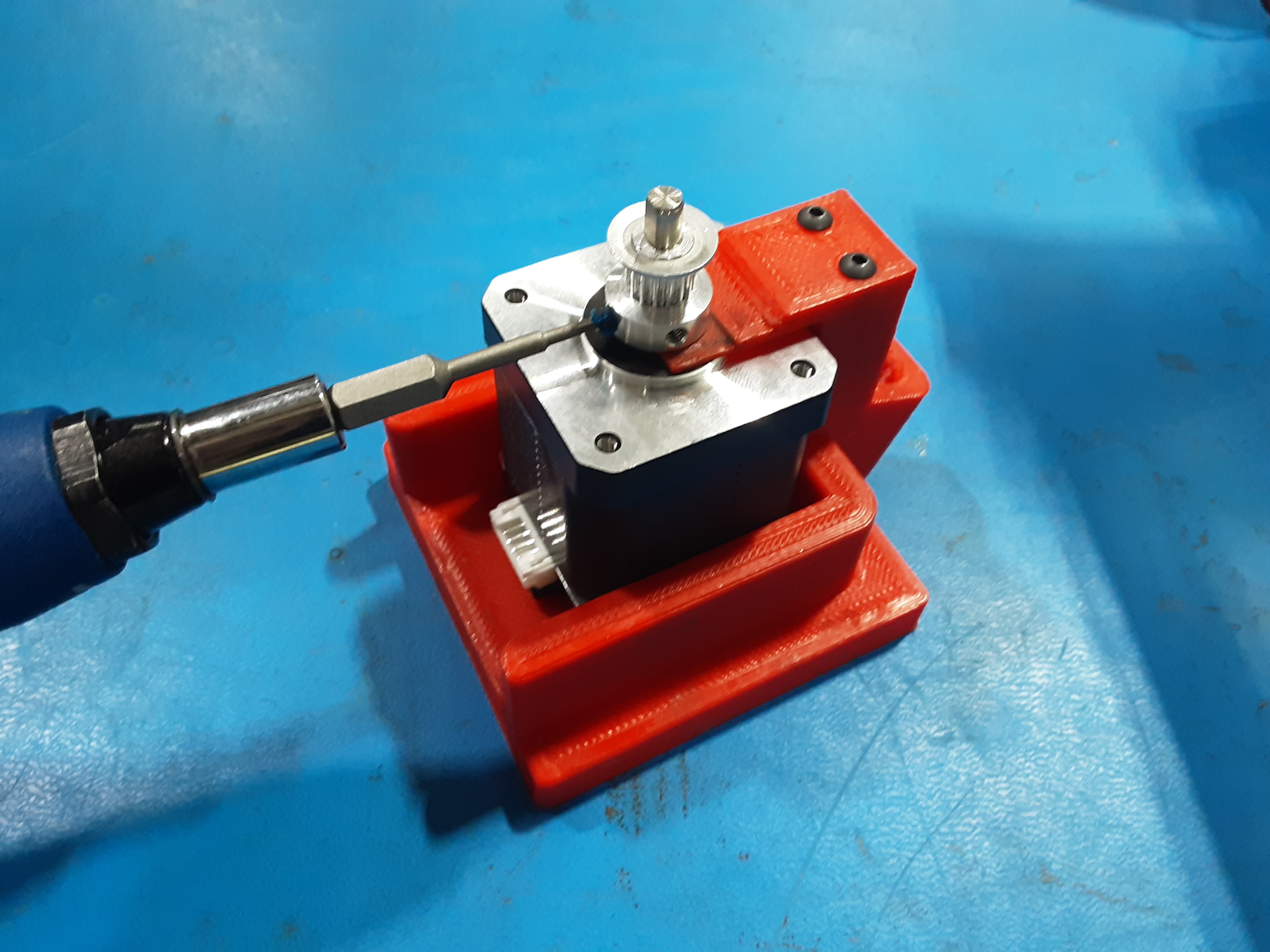
2C) Place EL-MT0068 in the motor jig.
2D) Set HD-MS0625 on the shaft of EL-MT0068.
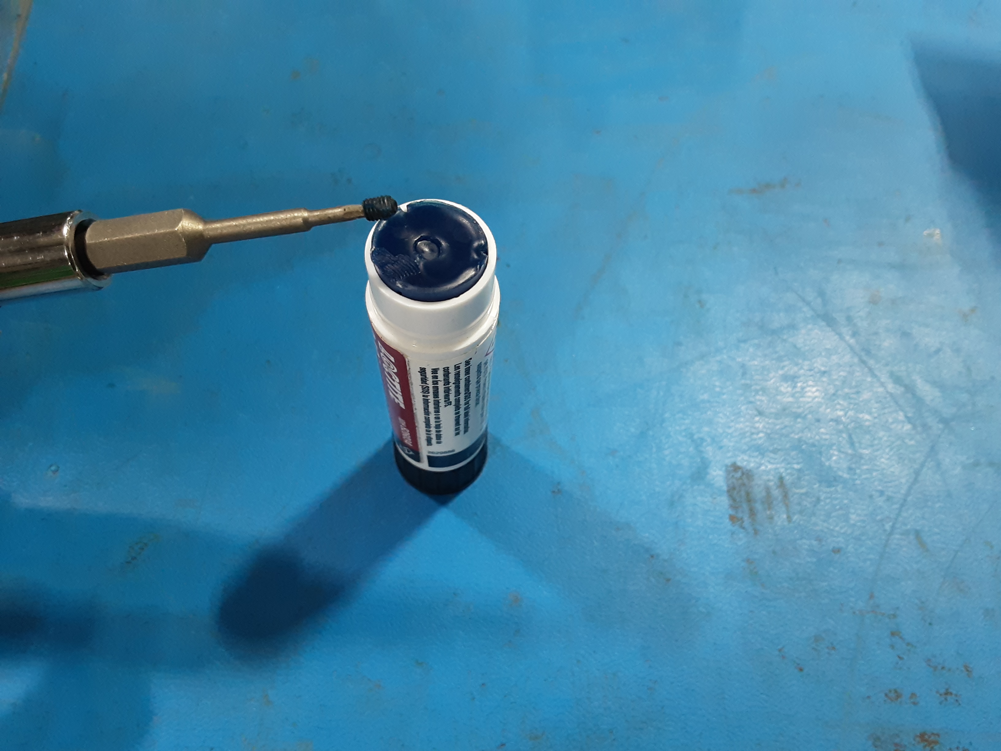
2E) With HD-MS0625 all the way down on the motor jig spacer apply blue loctite to the previously removed set screws and secure it to the motor shaft. Make sure one of the set screws is lined up with the flat side of the motor shaft.
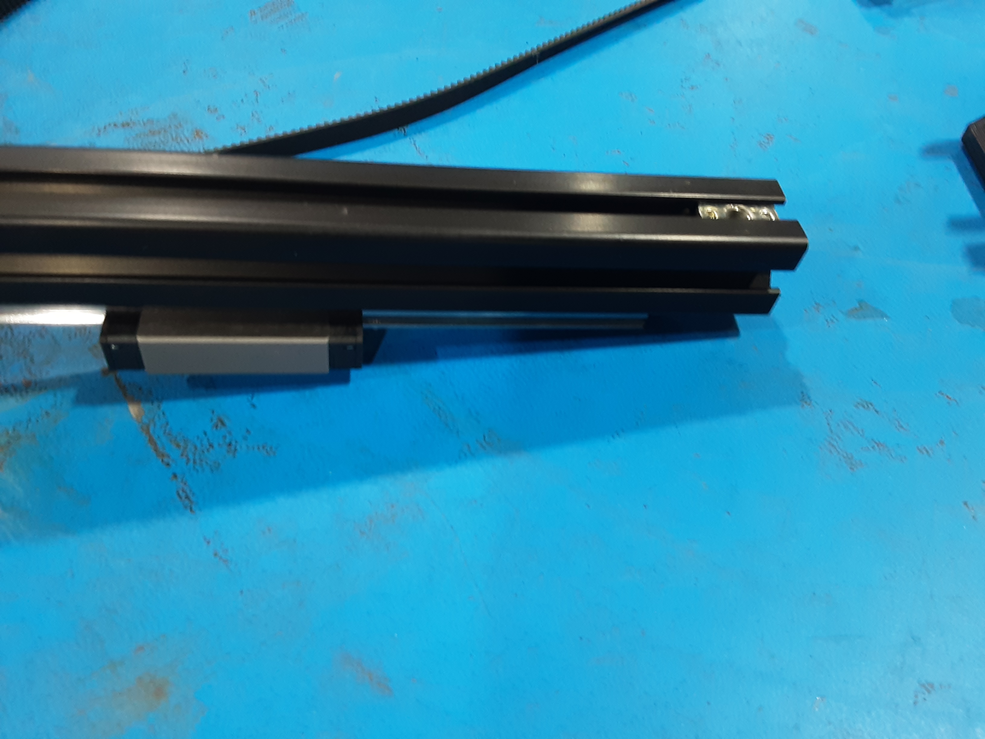
Extrusion Assembly
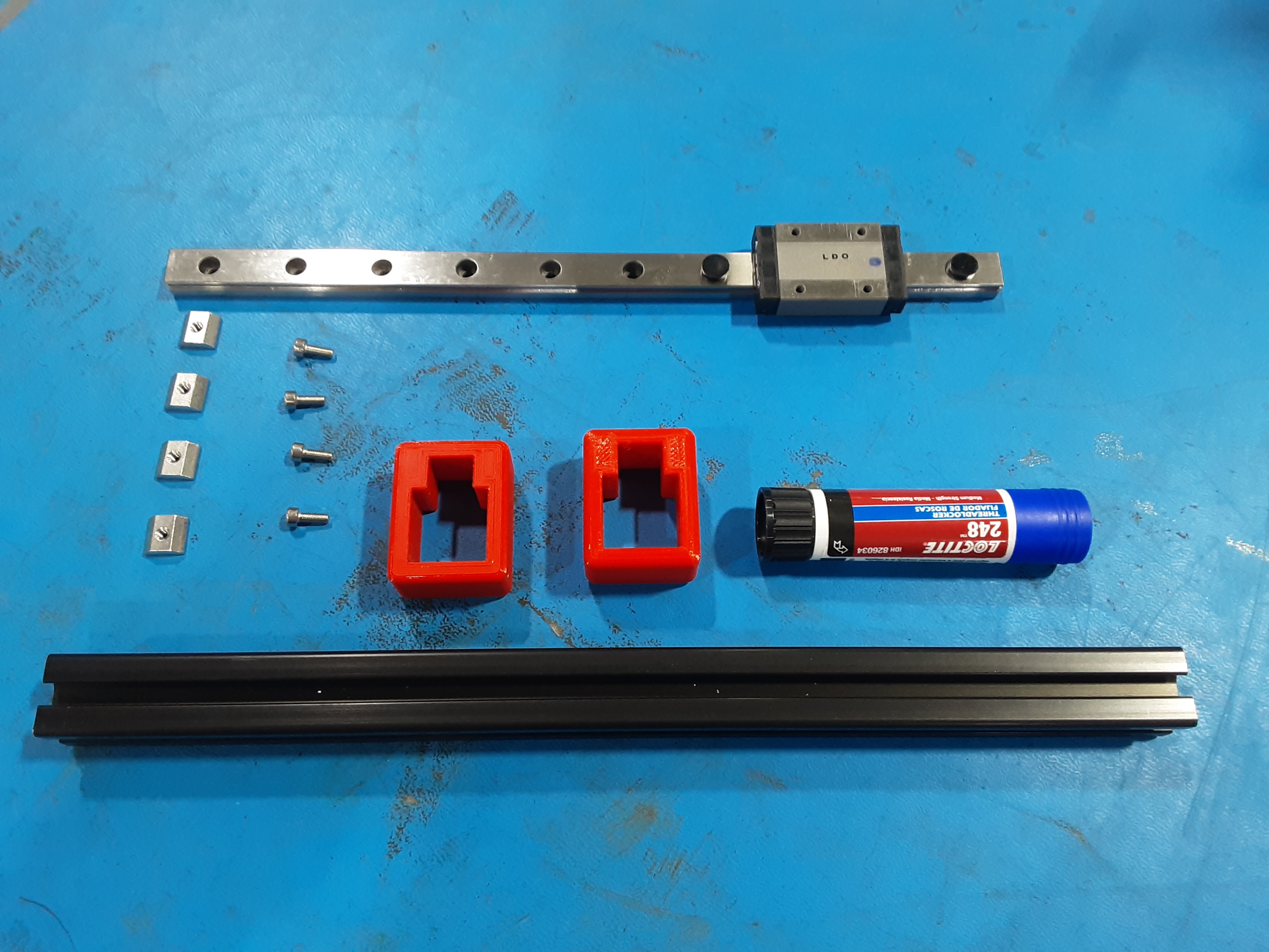
3A) Grab HD-EX0102 x1, HD-RD0051 x1, HD-NT0005 x4, HD-BT0170 x4, and two red jig blocks.
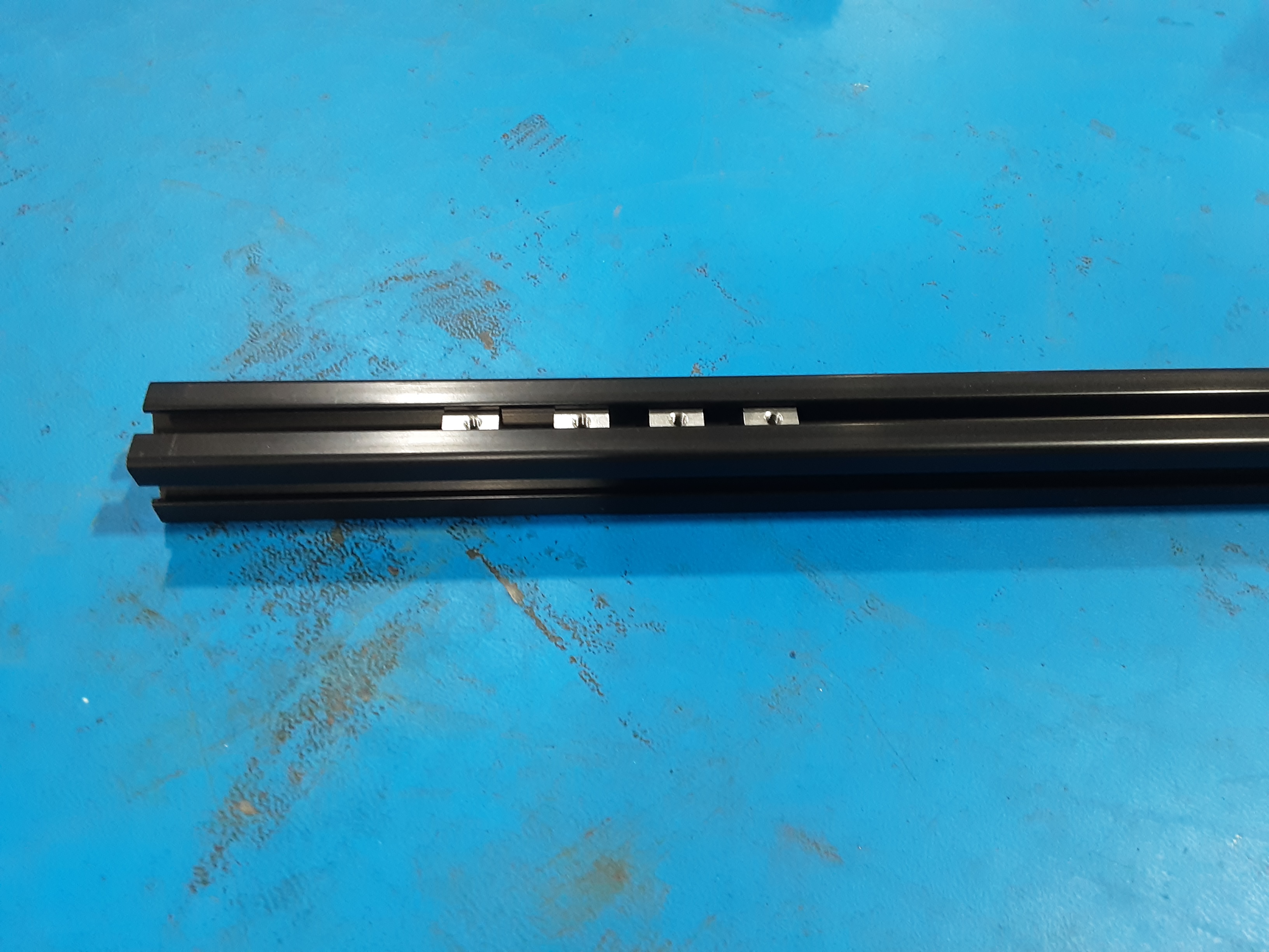
3B) Slide HD-NT0005 x4 into one side of HD-EX0102.
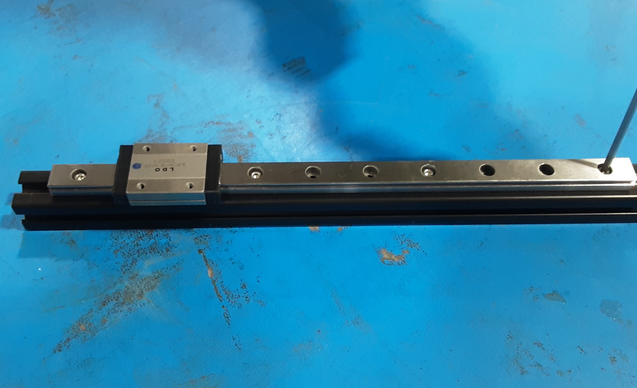
3C) Place HD-RD0051 on HD-EX0102. Apply blue loctite to HD-BT0170 x4 and loosely attach
HD-RD0051 to HD-EX0102 where shown.
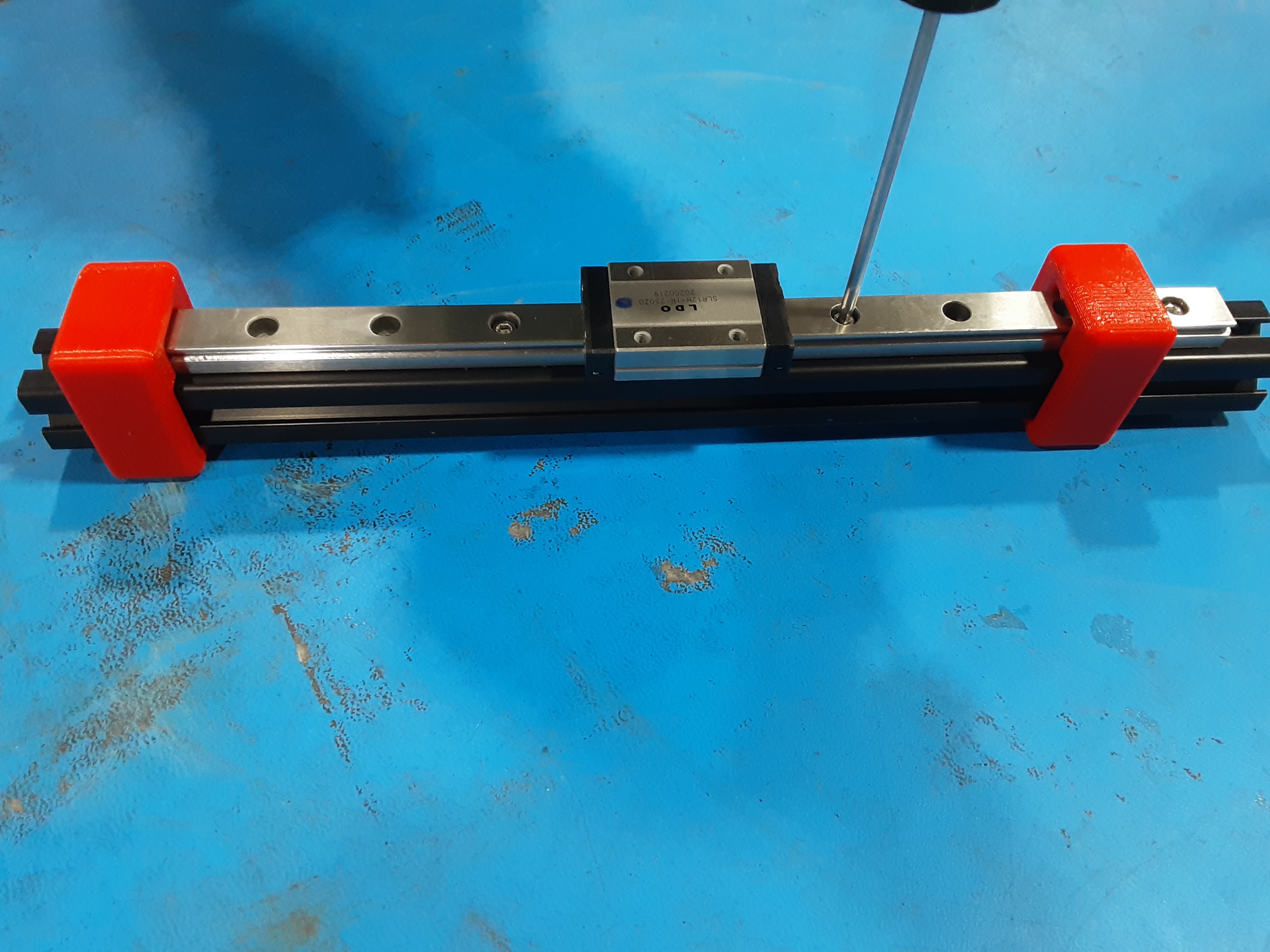
3D) Slide the red jig blocks onto the ends. With HD-RD0051 approximately centered on HD-EX0102 tighten HD-BT0170 x4.
Motor Side Rail Assembly
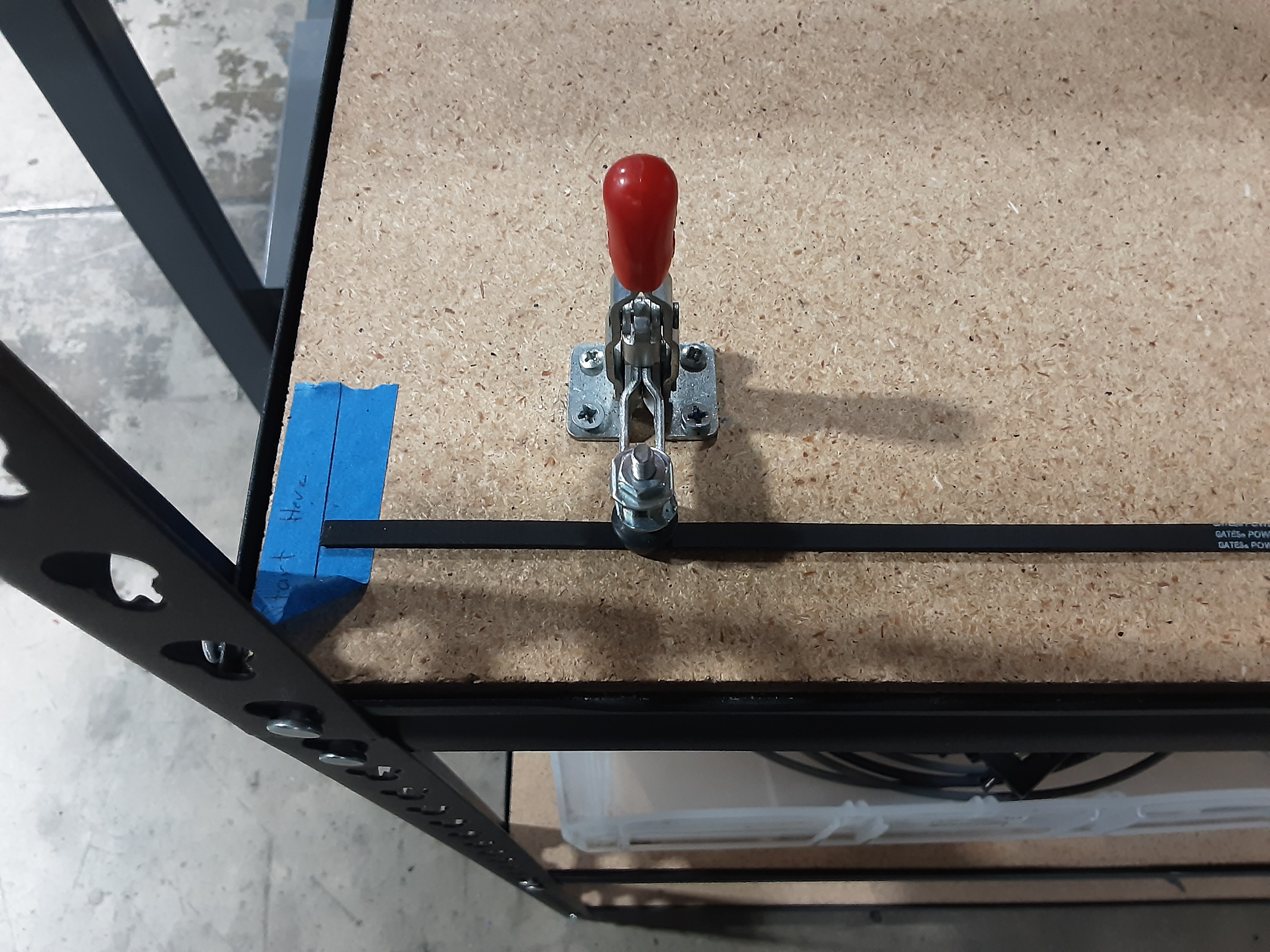
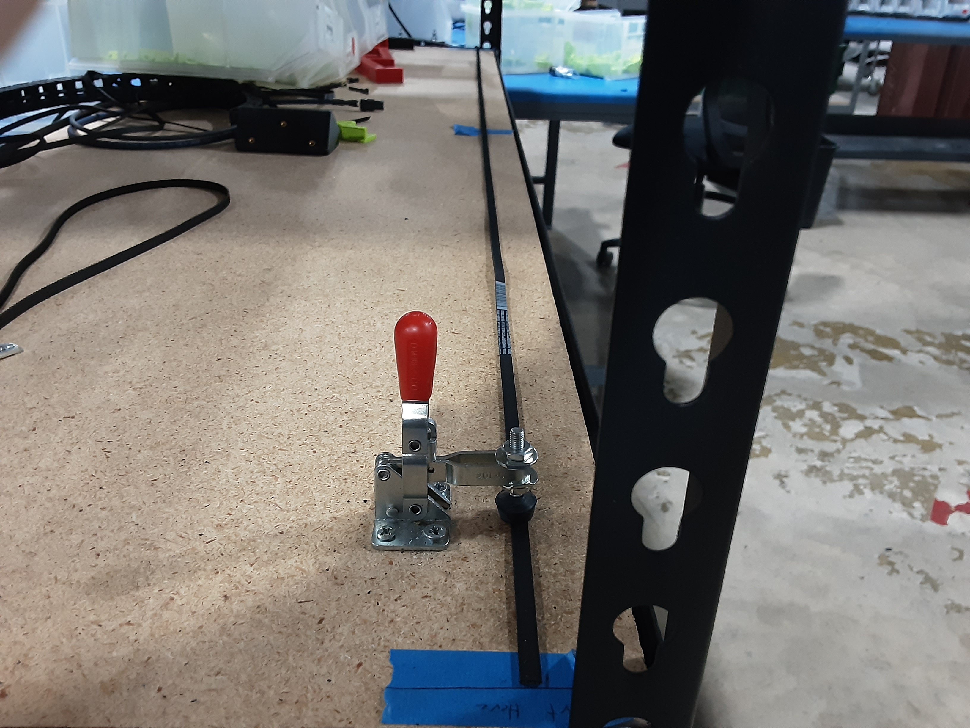
4A) At the belt cutting station, unspool enough HD-BL0037 to get the end to the “Start Here” line and use the clamp to hold the belt in place.
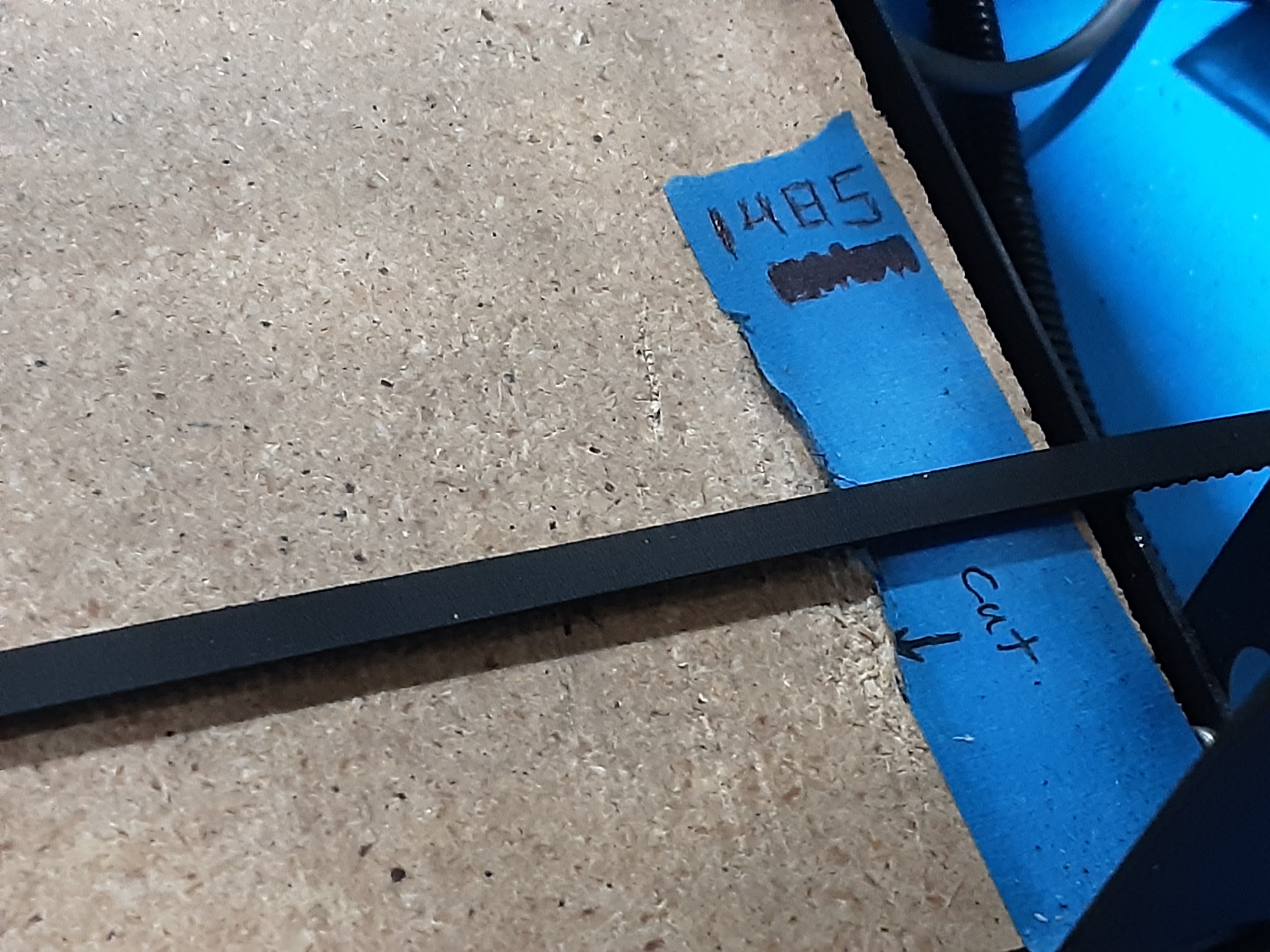
4B) Ensure that the belt does not have any twists and lays flat. Cut the belt at the “1485” cut line.
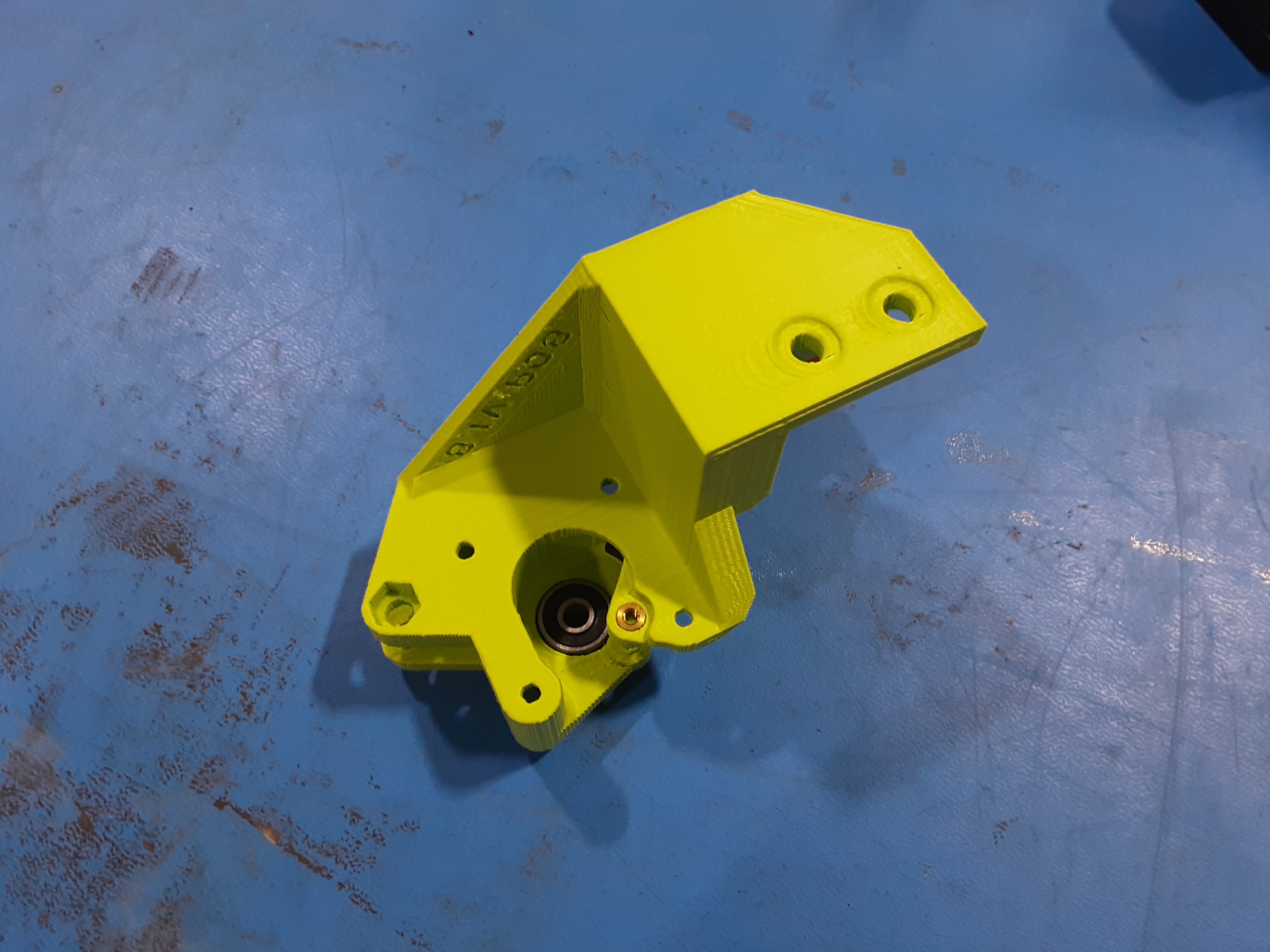
4C) Grab PP-GP0809 x1, HD-MS0411 x1, HD-MS0470 x2, HD-BT0157 x4, HD-BT0007 x1,
HD-BT0272 x1, 3HD-WA0038 x5, HD-NT0057 x1, HD-BU0035 x2, and Motor Assembly.
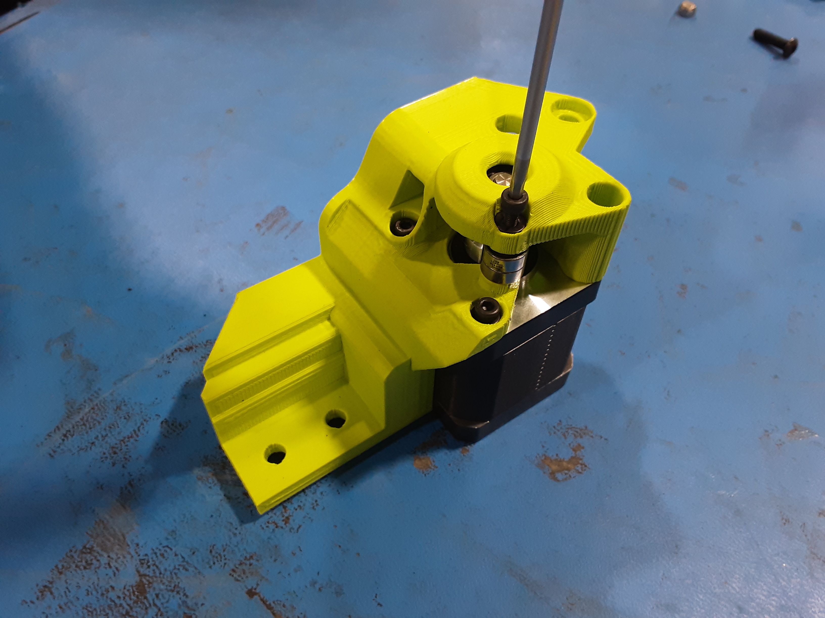
4D) Install HD-MS0411 into PP-GP0809.
4E) Line up and push the motor into PP-GP809 with the motor shaft going into HD-MS0411.
4F) Secure the Motor to PP-GP0809 using HD-BT0157 x4 and HD-WA0038 x4.
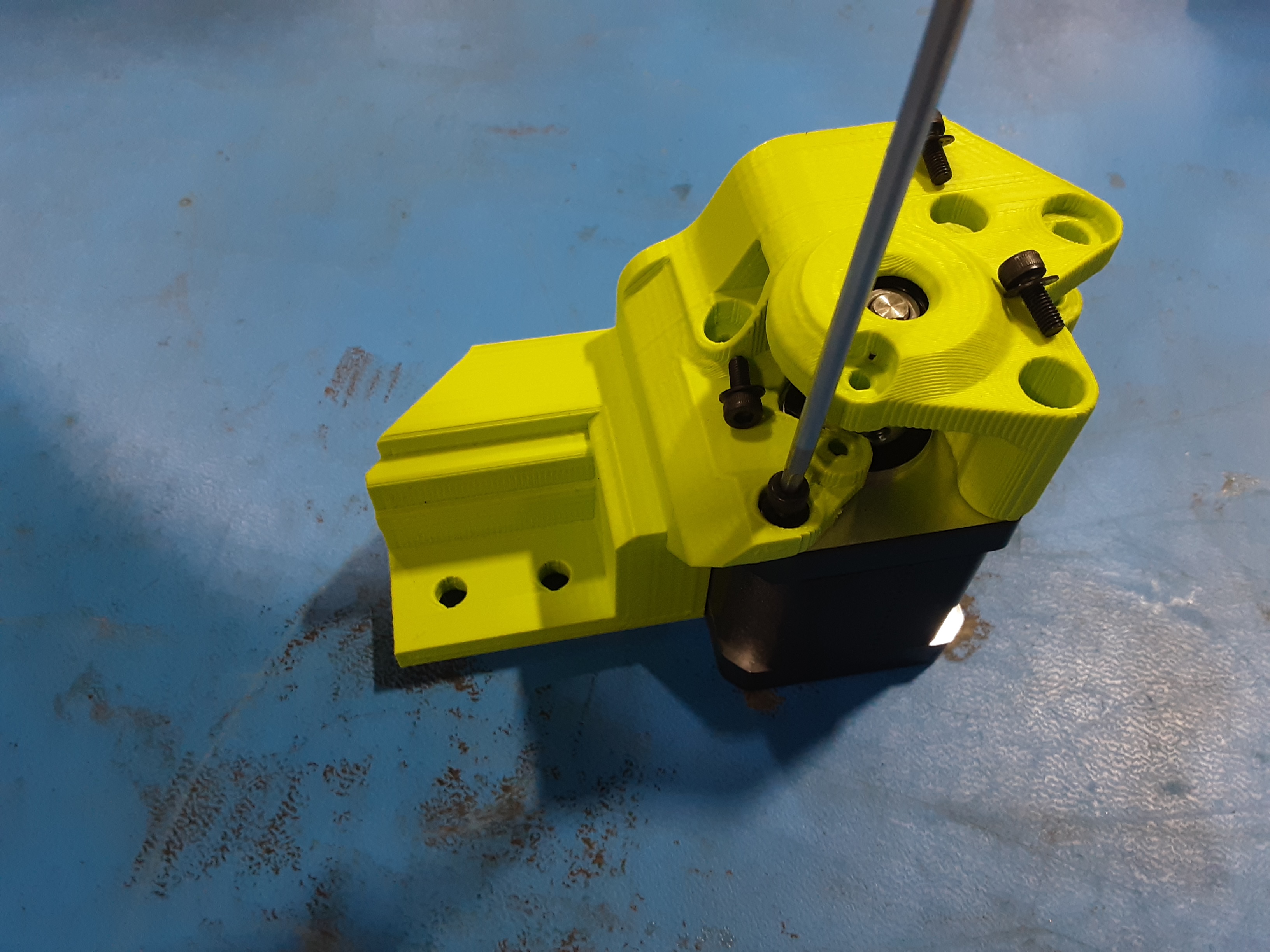
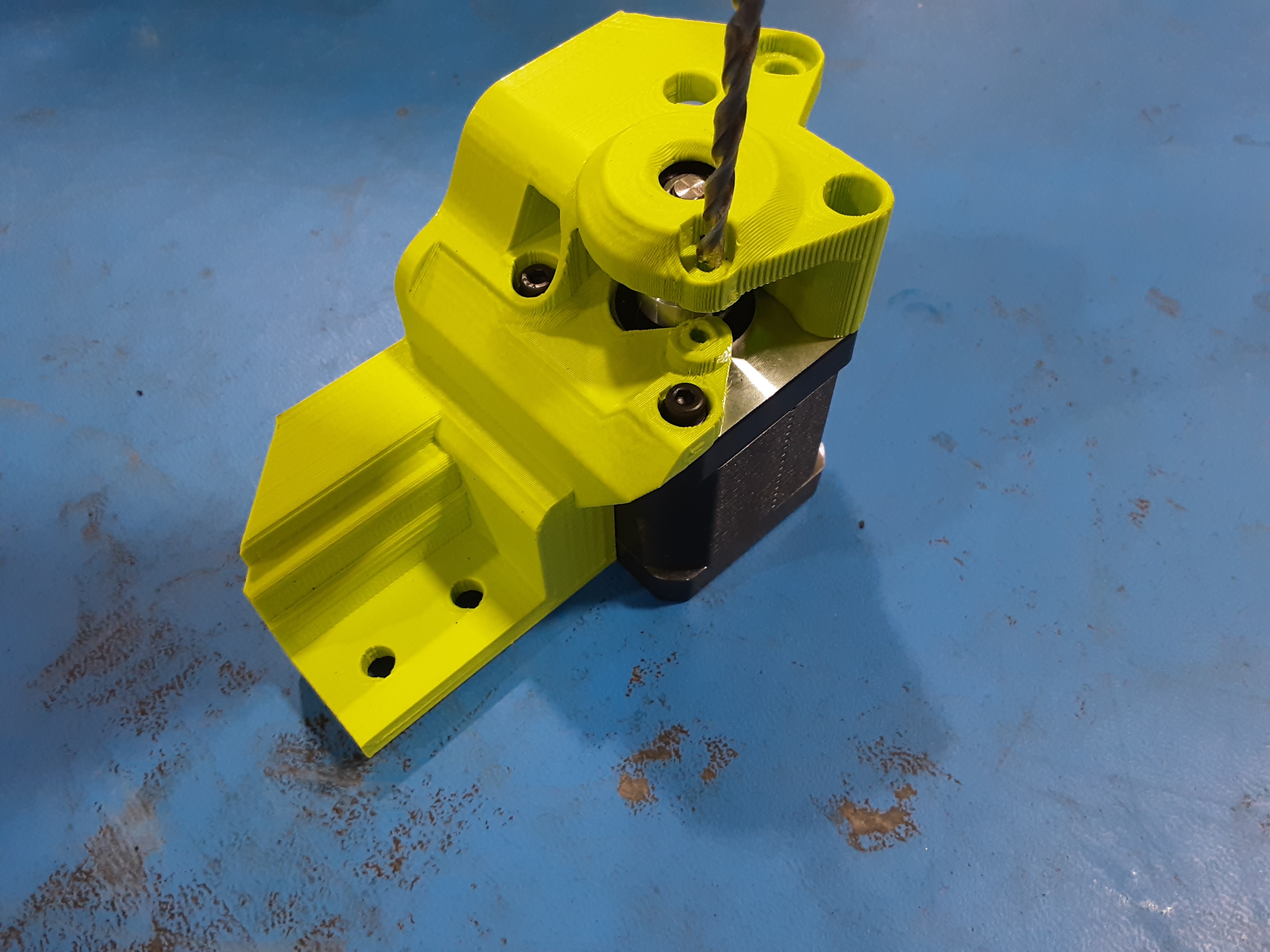
4G) Using a #28 drill bit clean out just the first layer of the shown hole.
4H) Place HD-MS0470 x2 under the now clean hole and secure them with HD-BT0007 x1 and
HD-WA0038 x1.
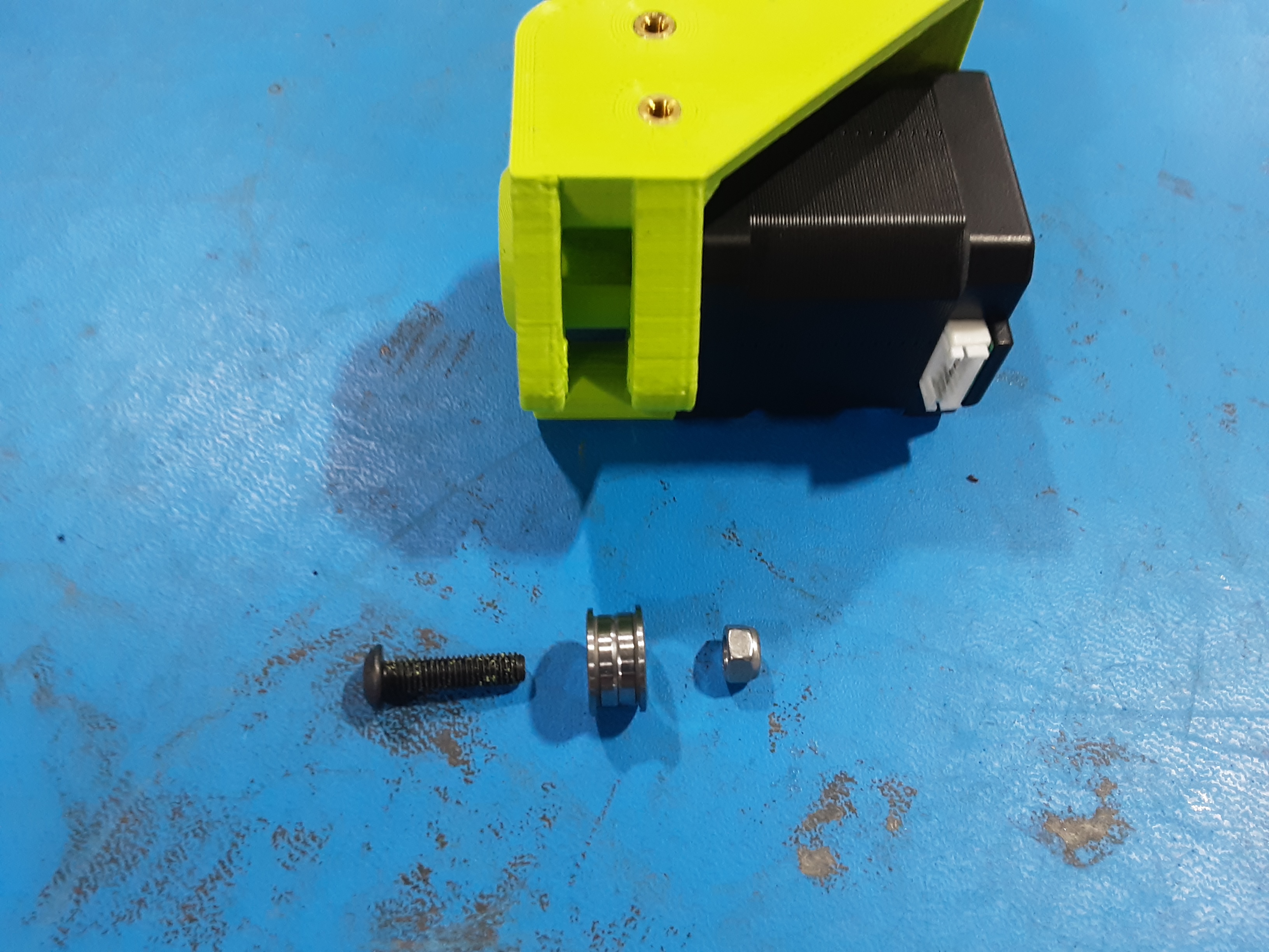
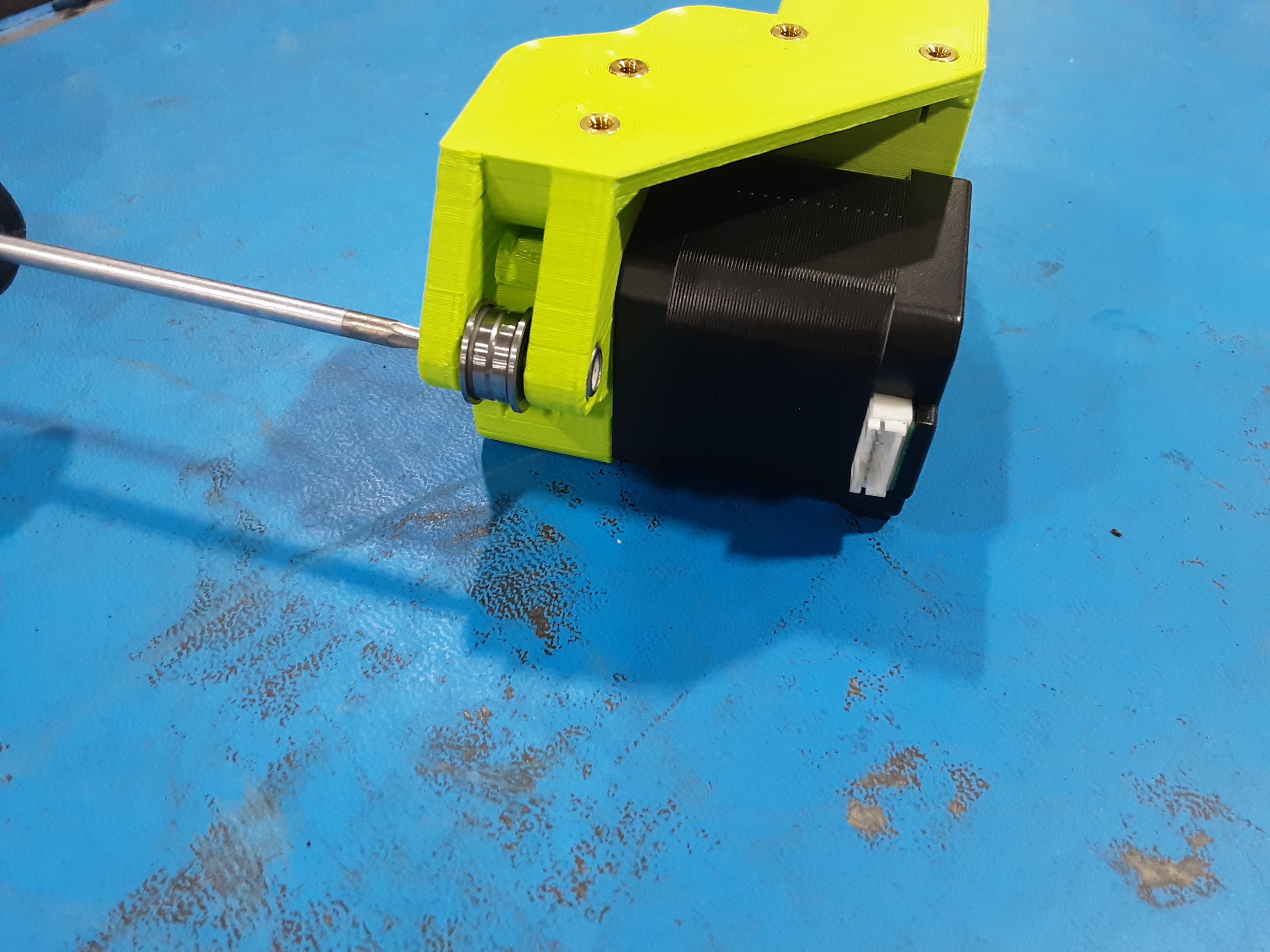
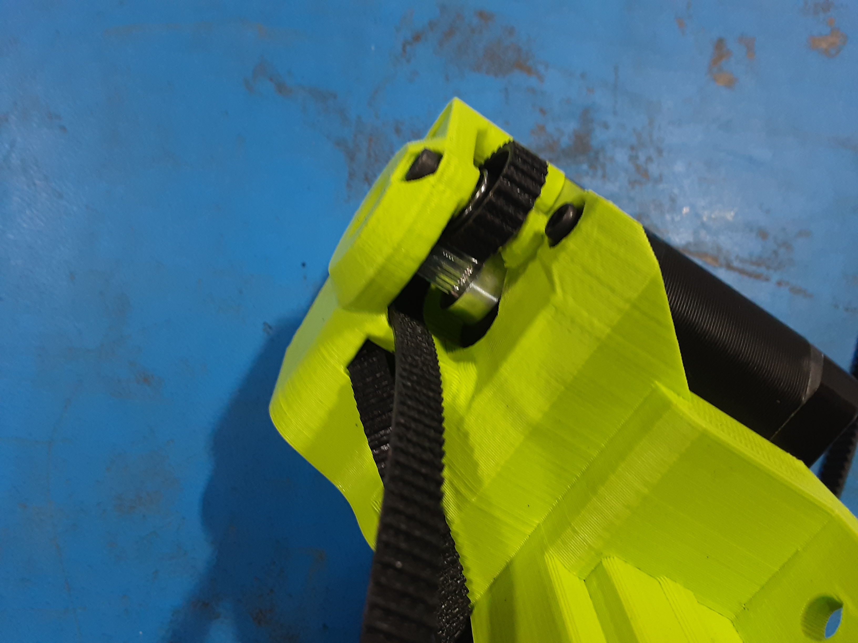
4I) Grab HD-BT0272 x1, HD-BU0035 x2, and HD-NT0057 x1.
4J) Position the smaller sides of HD-BU0035 x2 together and place them in PP-GP0809. Secure
HD-BU0035 x2 in PP-GP0809 using HD-BT0272 x1 and HD-NT0057 x1.
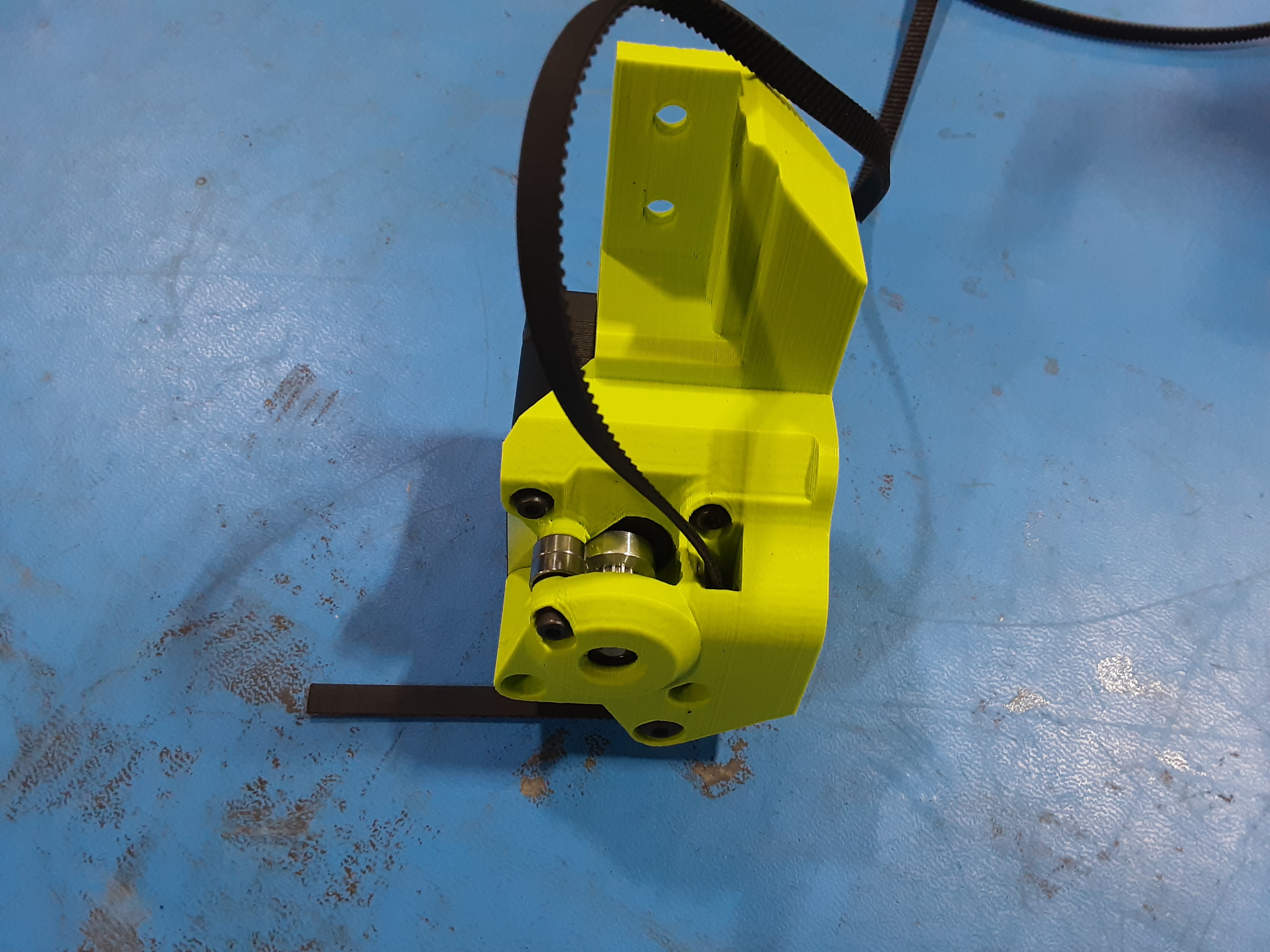
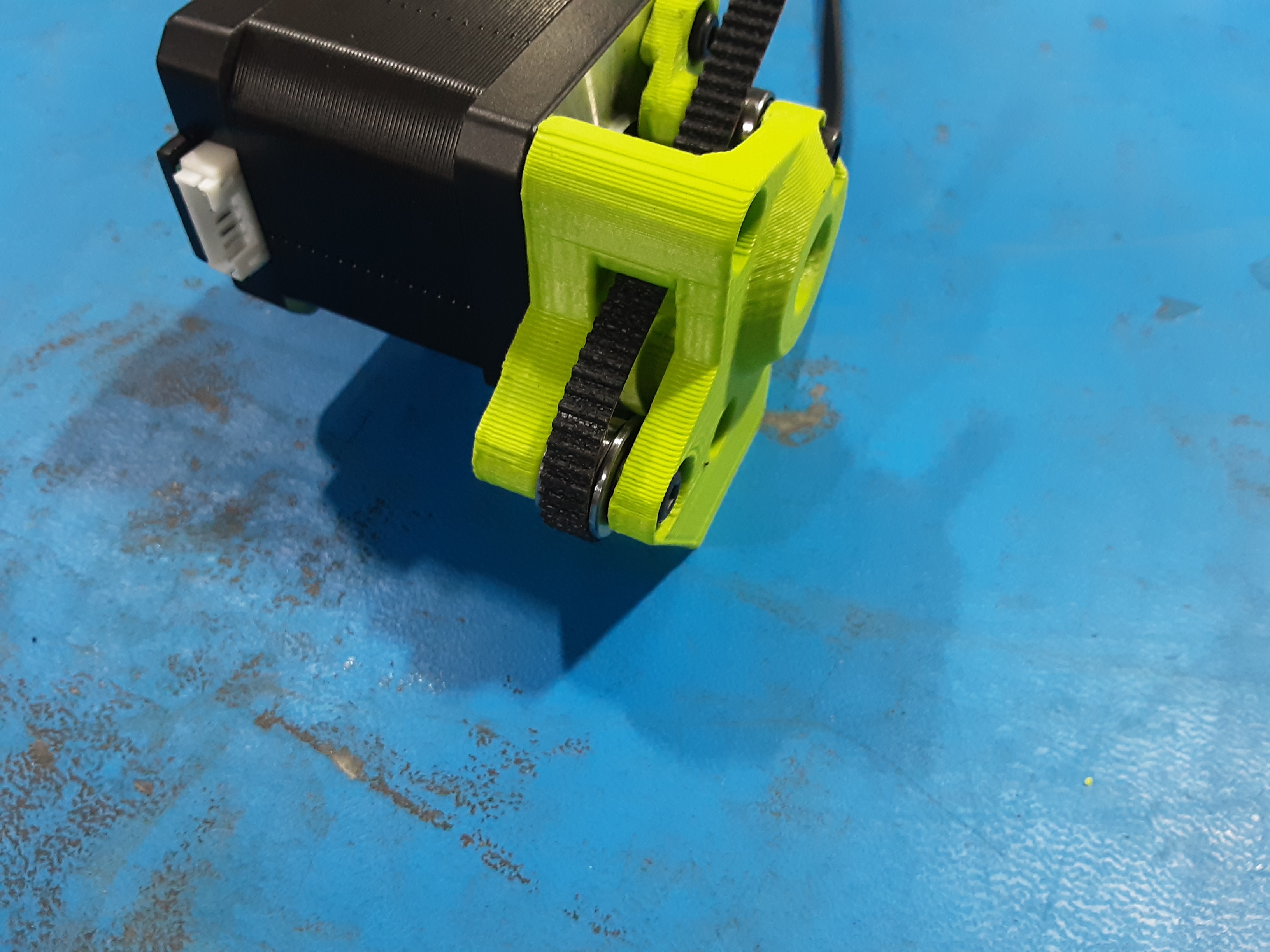
4K) Feed HD-BL0037 through PP-GP0809 as shown.
4L) Wrap the lead end of HD-BL0037 around HD-BU0035 x2 and back through PP-GP0809.
4M) Wrap the lead end of HD-BL0037 around HD-MS0470 x2 guiding it to wrap around HD-MS0625. Then pull HD-BL0037 to have about the same length on each side coming out of PP-GP0809.
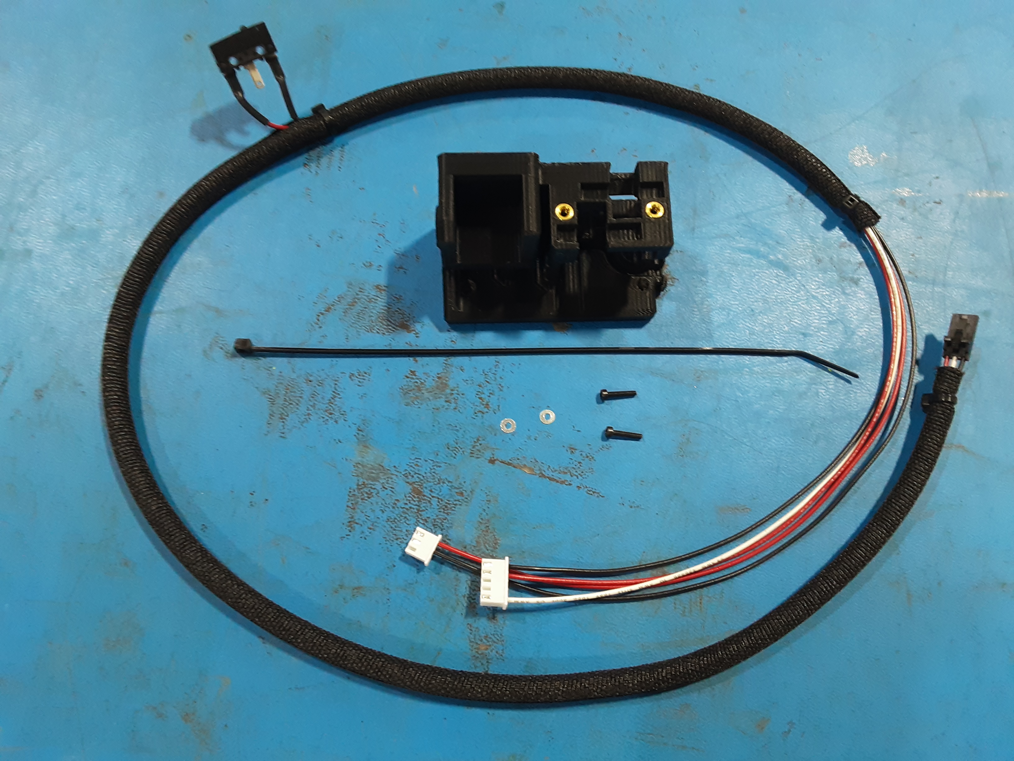
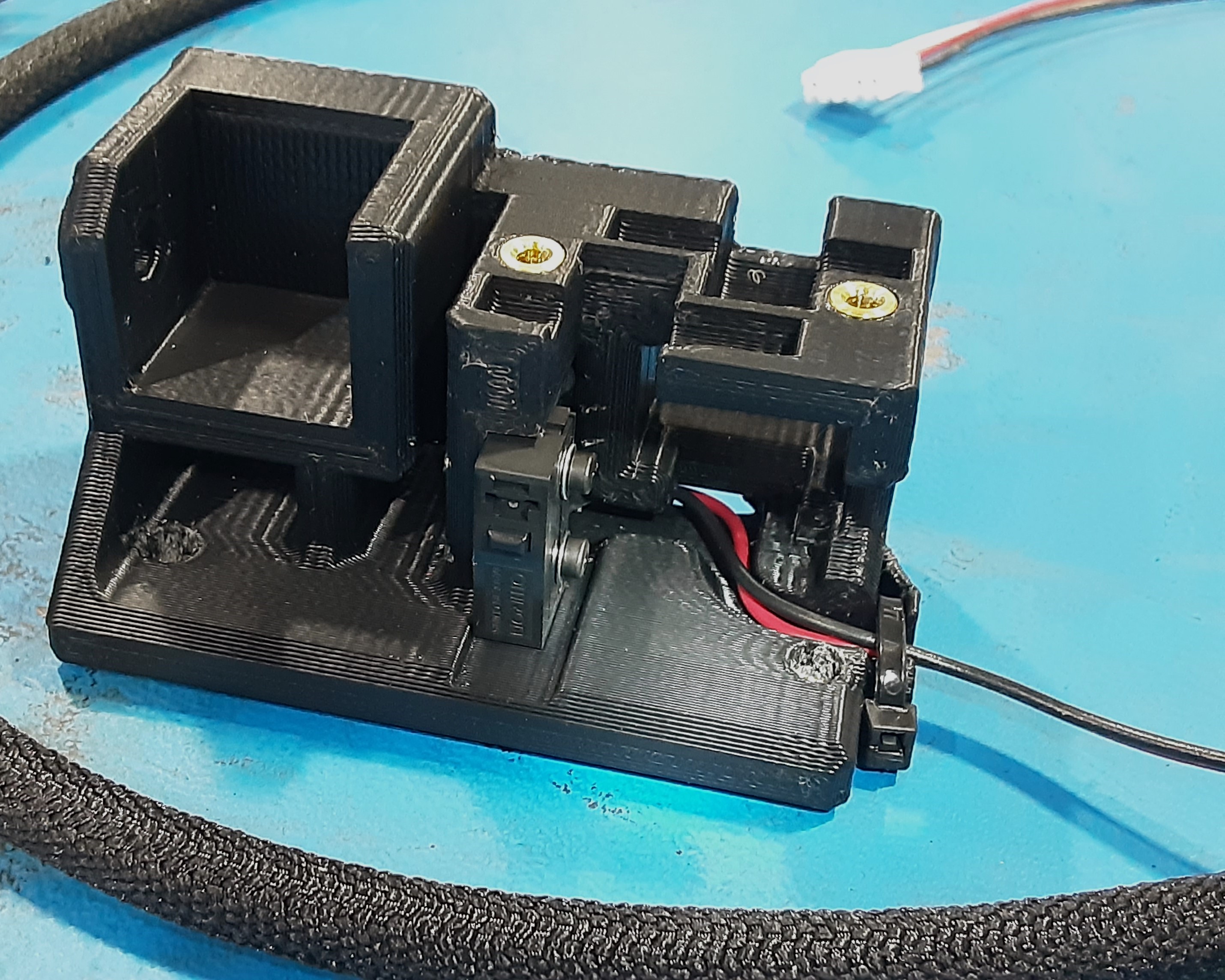
Wire Side Rail Assembly
5A) Grab PP-GP0827 x1, EL-HR0214 x1, HD-BT0107 x2, HD-WA0012 x2, and HD-MS0058 x1.
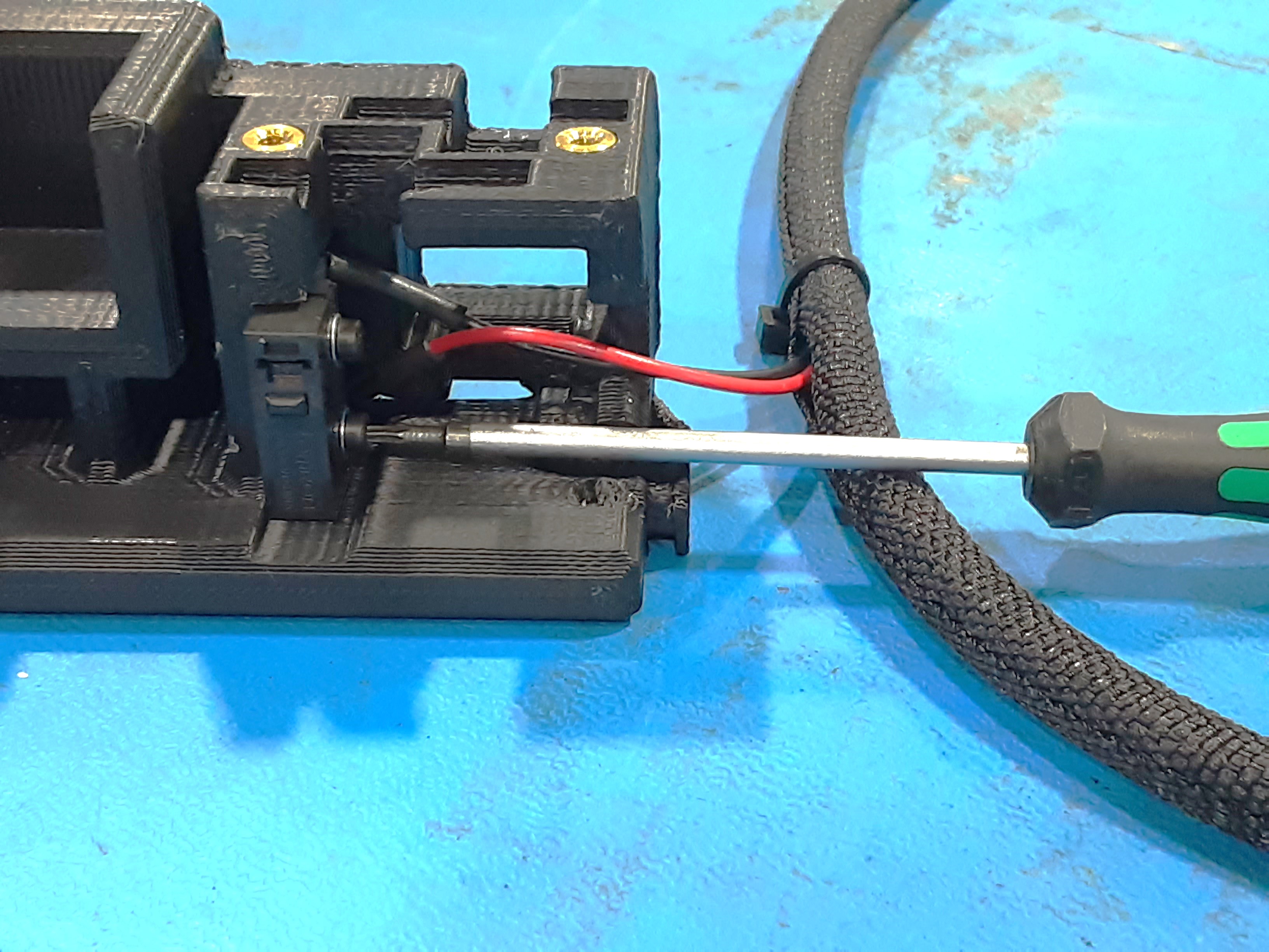
5B) Pull the switch from EL-HR0214 out of the braiding a little bit. Attach the switch to PP-GP0827 in the shown orientation using HD-BT0107 x2 and HD-WA0012 x2.
5C) Run the wires through the channel in PP-GP0827 and secure using HD-MS0058 x1 as shown.
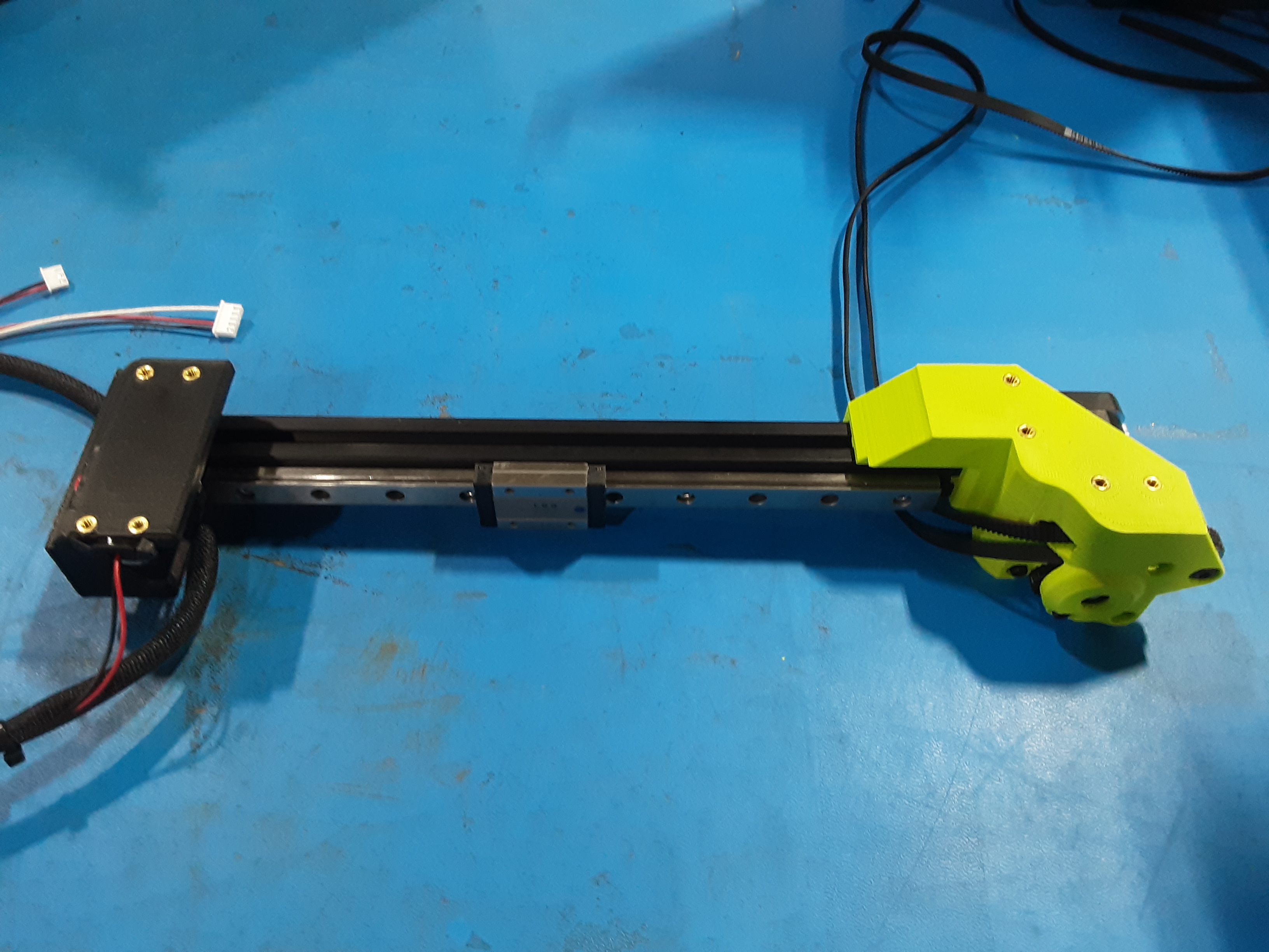
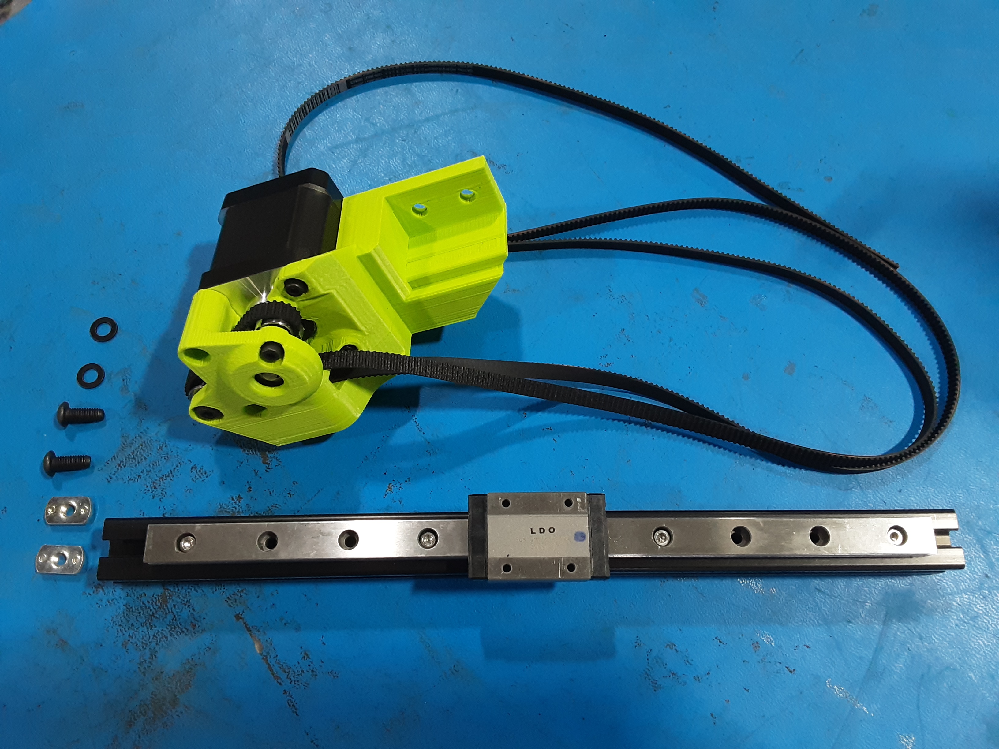
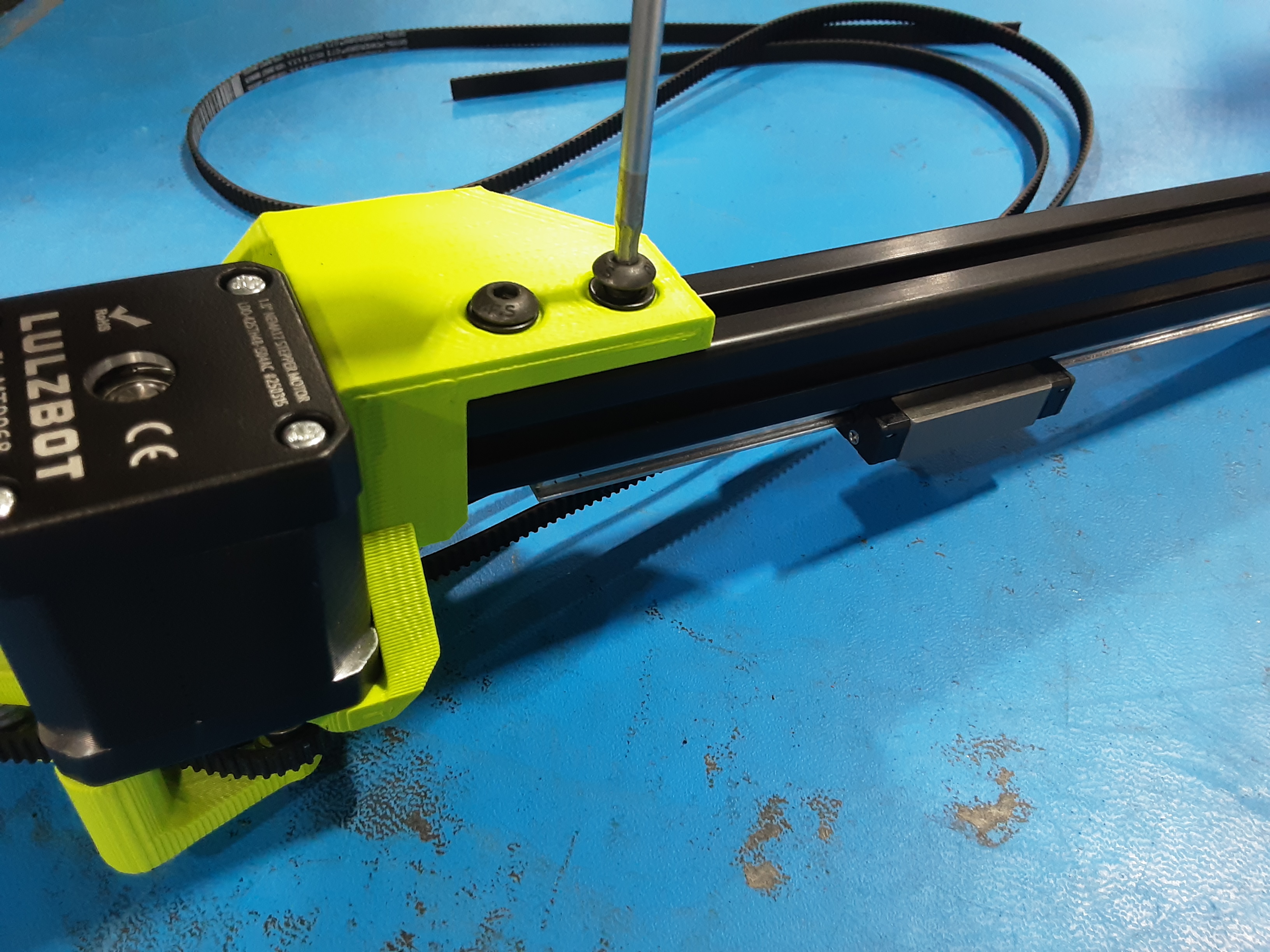
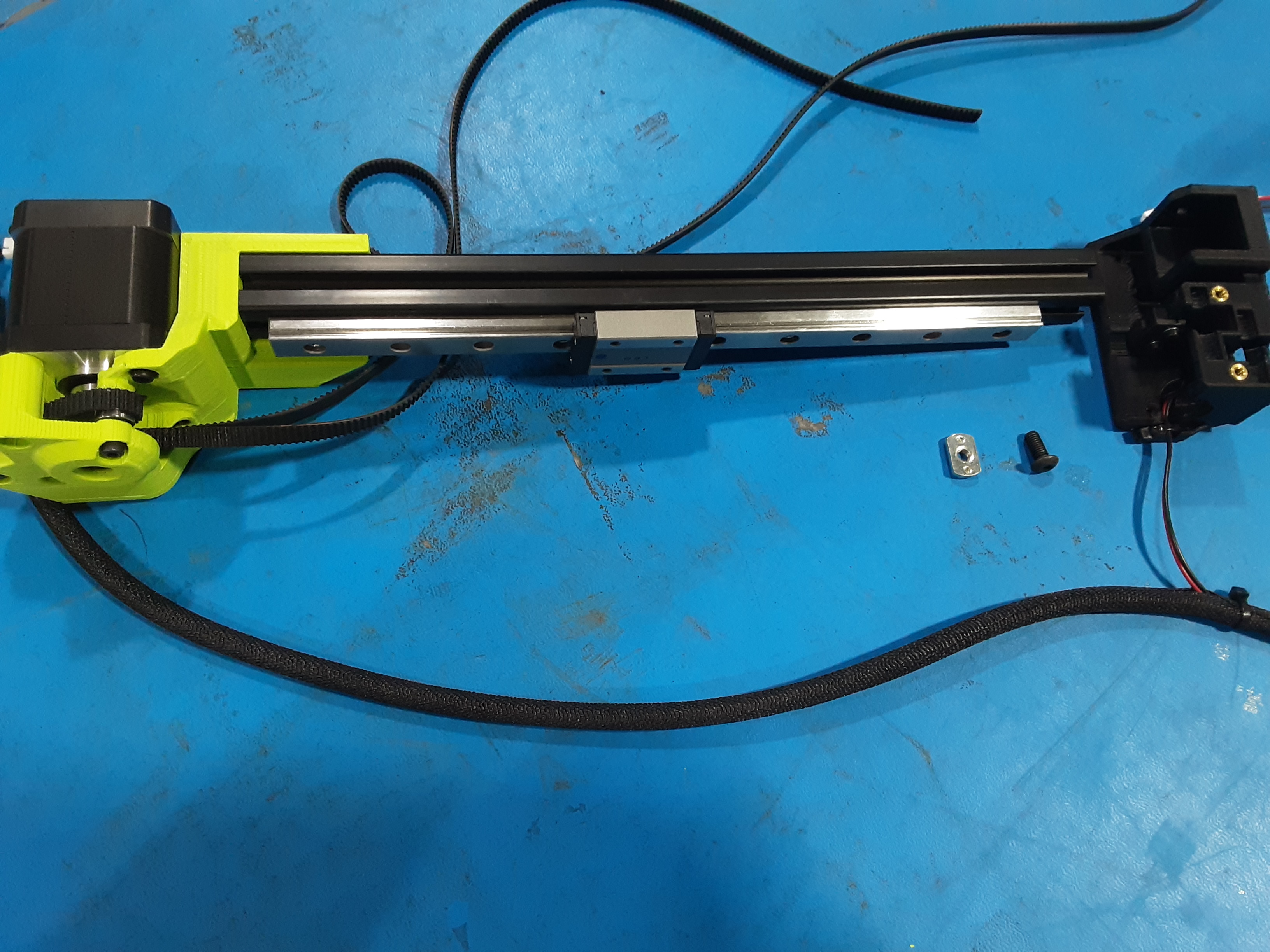
Rail Assembly
6A) Grab HD-NT0053 x2, HD-BT0158 x2, HD-WA0040 x2, Motor Side Rail Assembly, and Extrusion Assembly.
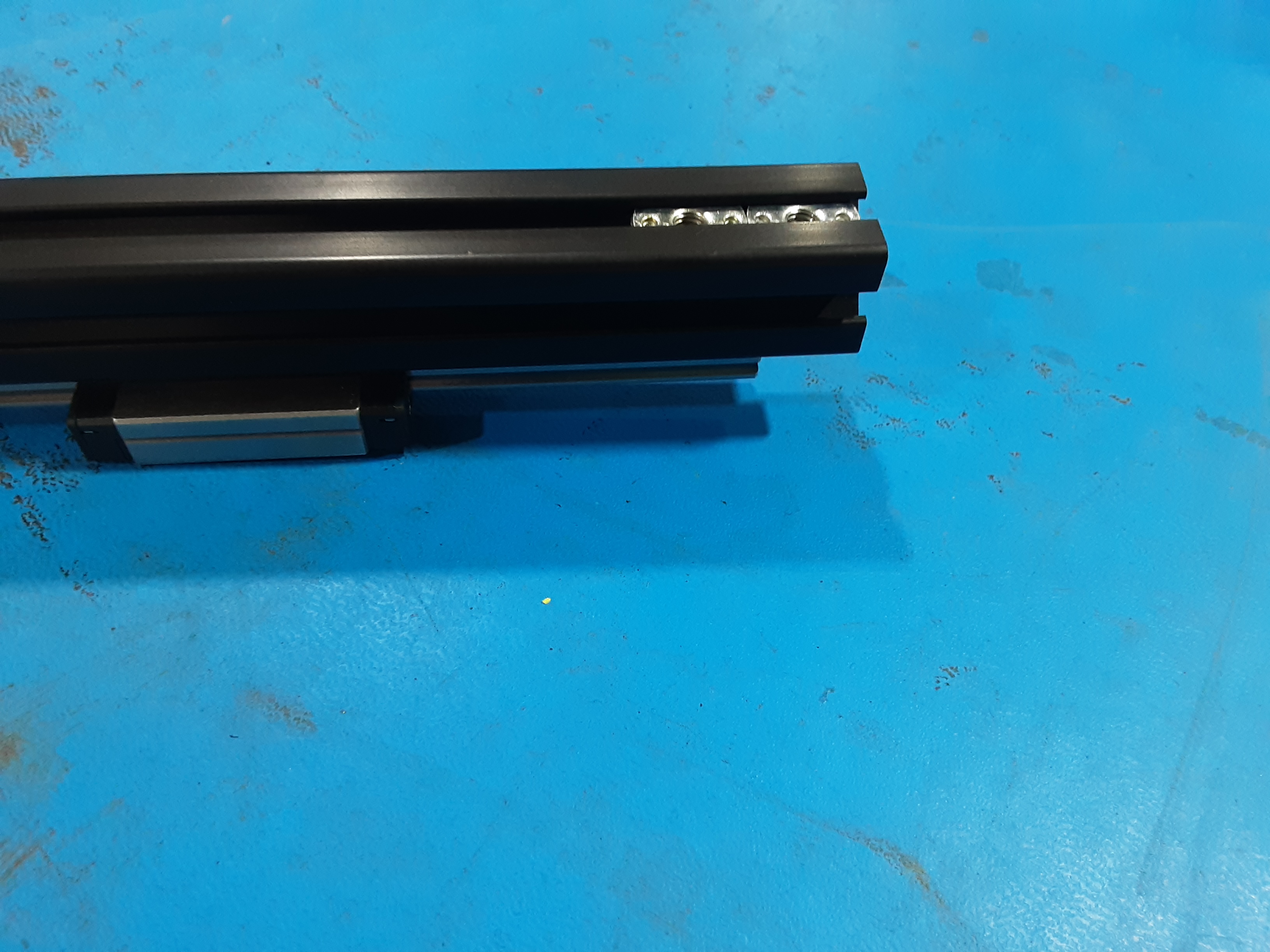
6B) Slide HD-NT0053 x2 into HD-EX0102 on the opposite side of HD-RD0051.
6C) Line up holes in PP-GP0809 with the HD-NT0053 x2 in HD-EX0102 and secure using HD-BT0158 x2 and HD-WA0040 x2. Make sure HD-EX0102 is all the way back and flush in PP-GP0809.
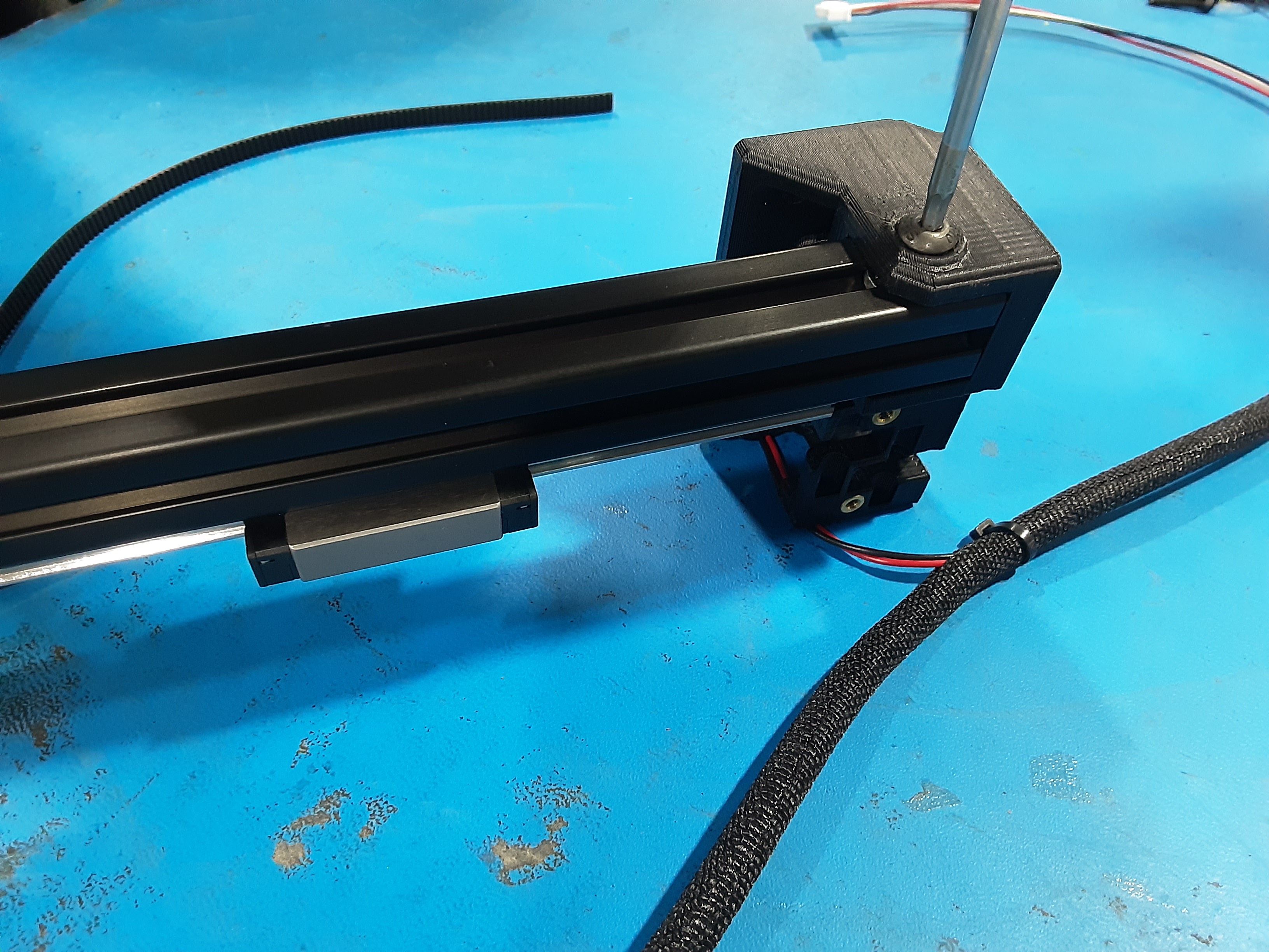
6D) Grab HD-NT0053 x1, HD-BT0158 x1, Wire Side Rail Assembly, and Extrusion Assembly.
6E) Slide HD-NT0053 x1 into HD-EX0102 on the opposite side of HD-RD0051.
6F) Line up hole in PP-GP0827 with the HD-NT0053 in HD-EX0102 and secure using HD-BT0158 x1. Make sure HD-EX0102 is all the way back and flush in PP-GP0827.
Final Steps
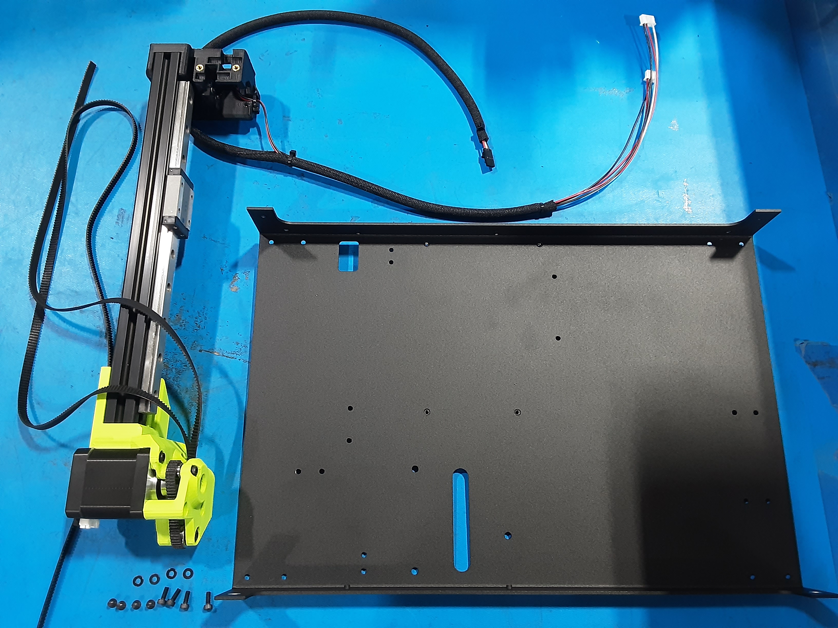
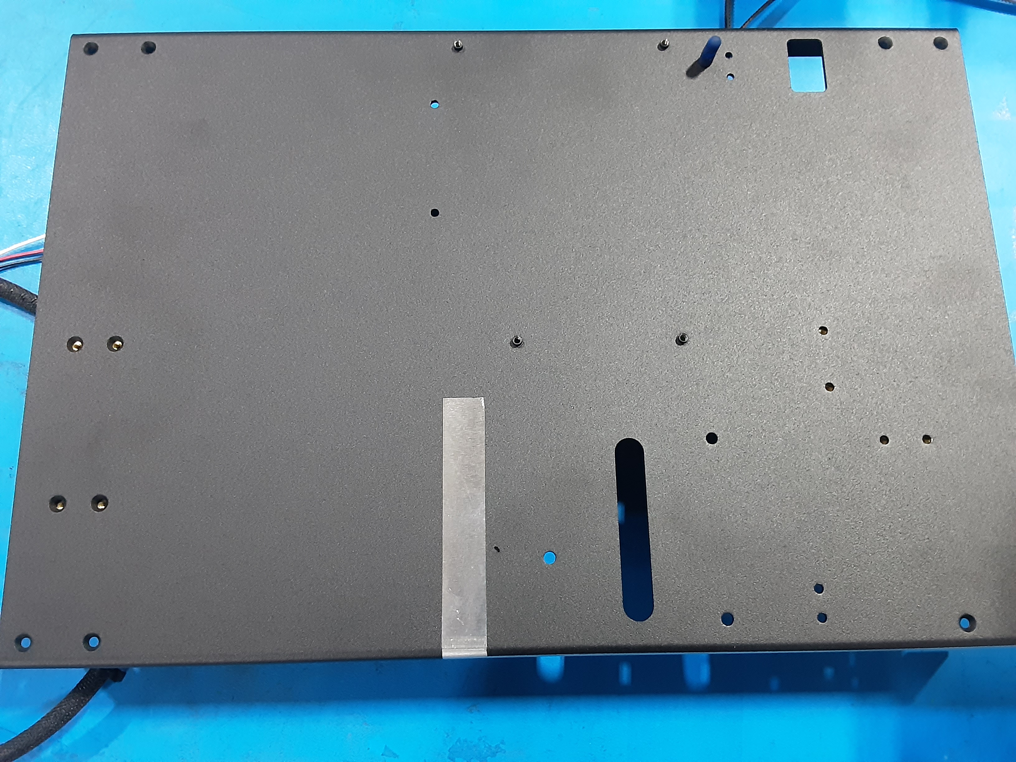
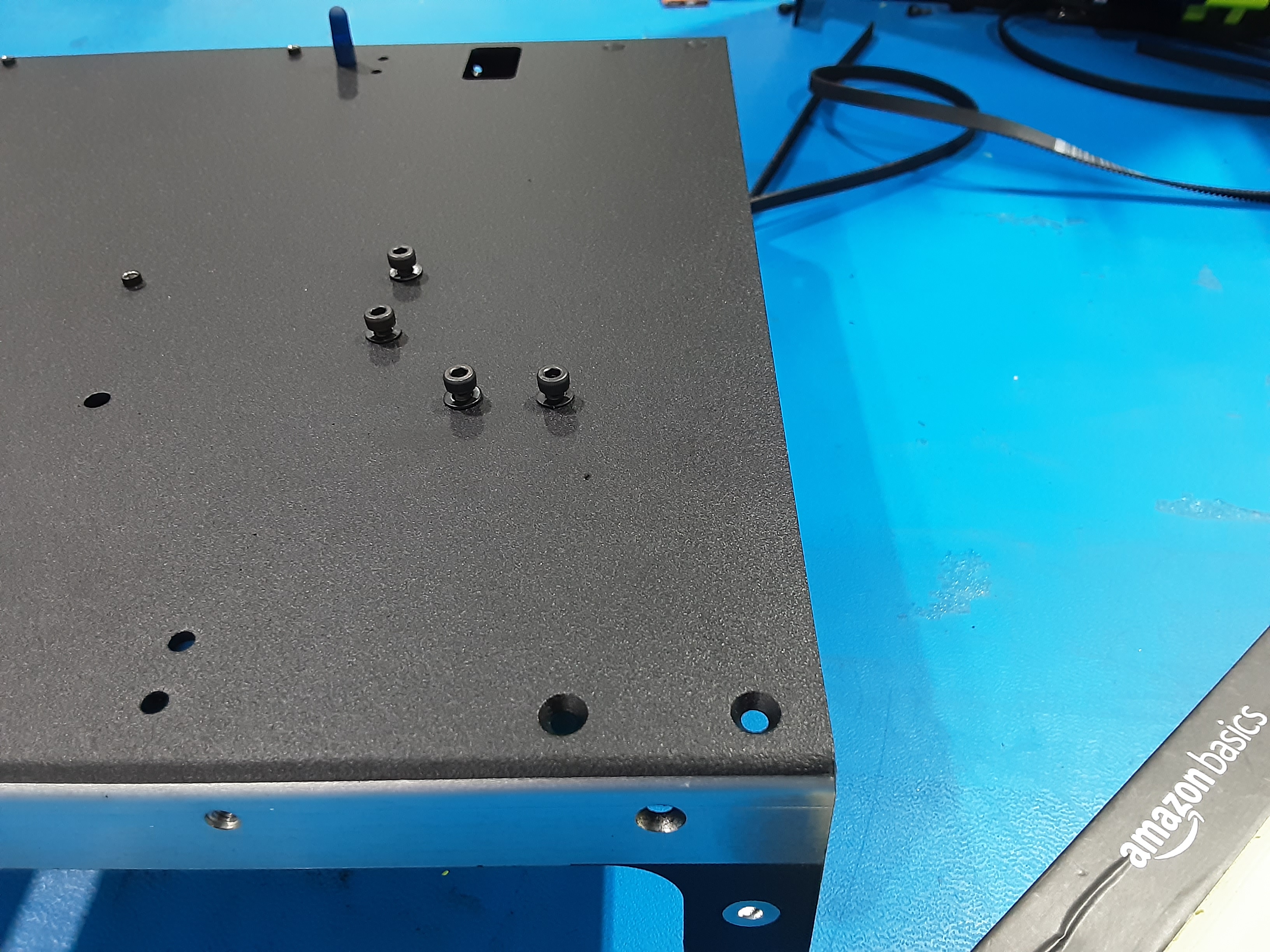
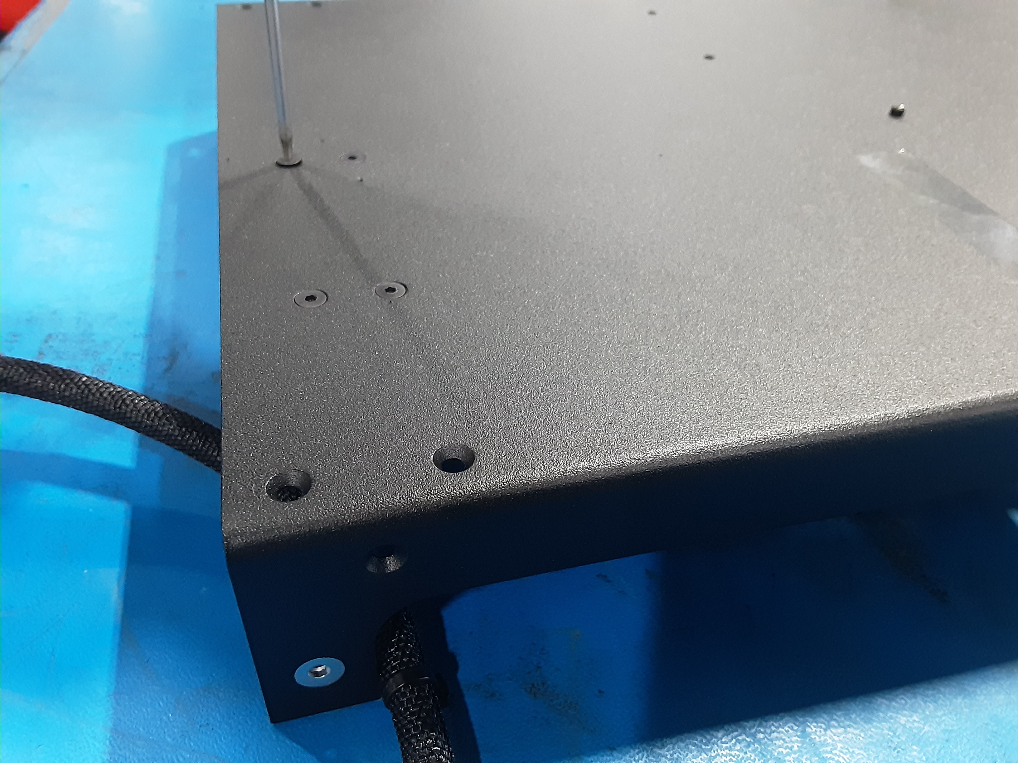
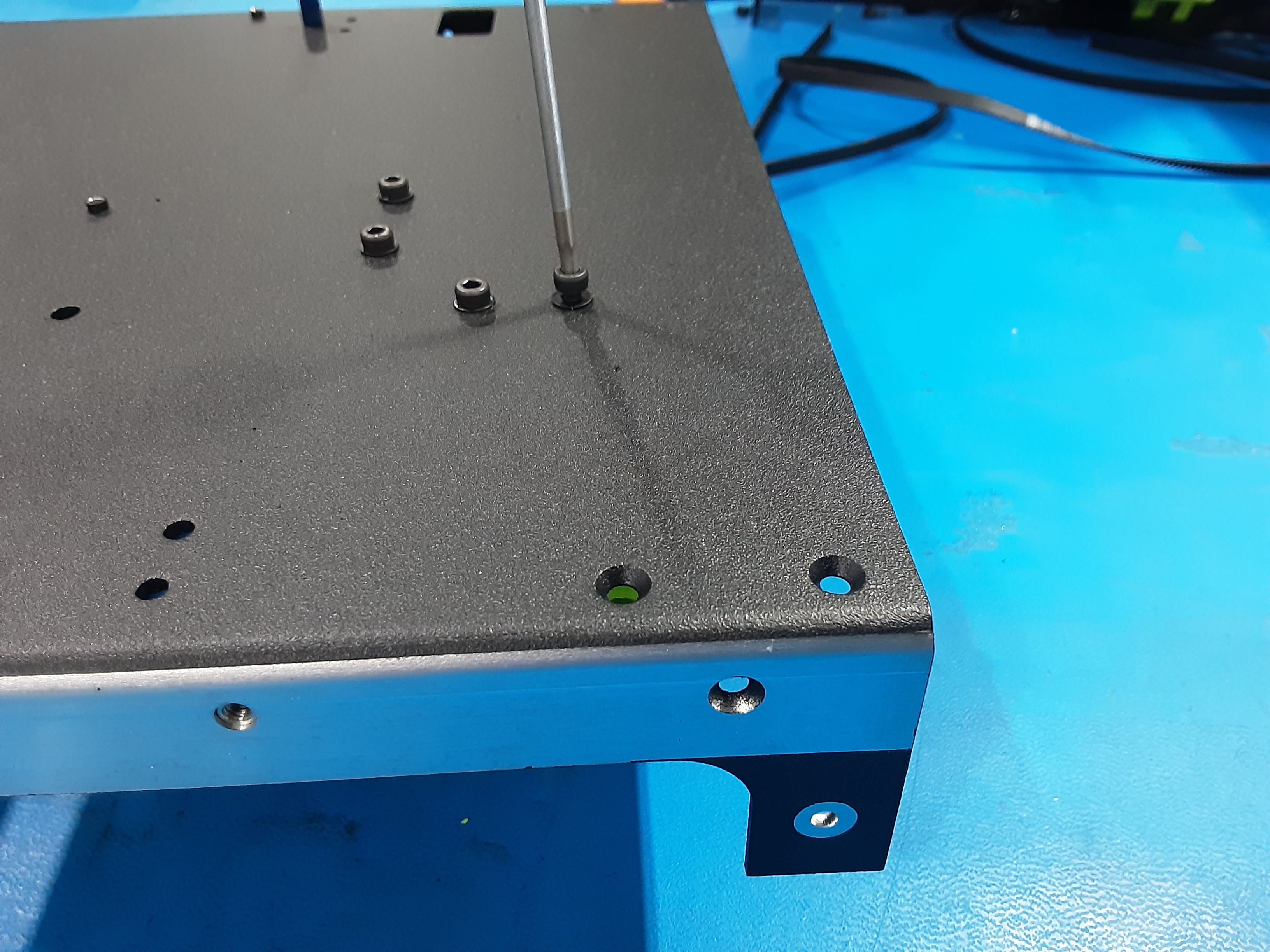
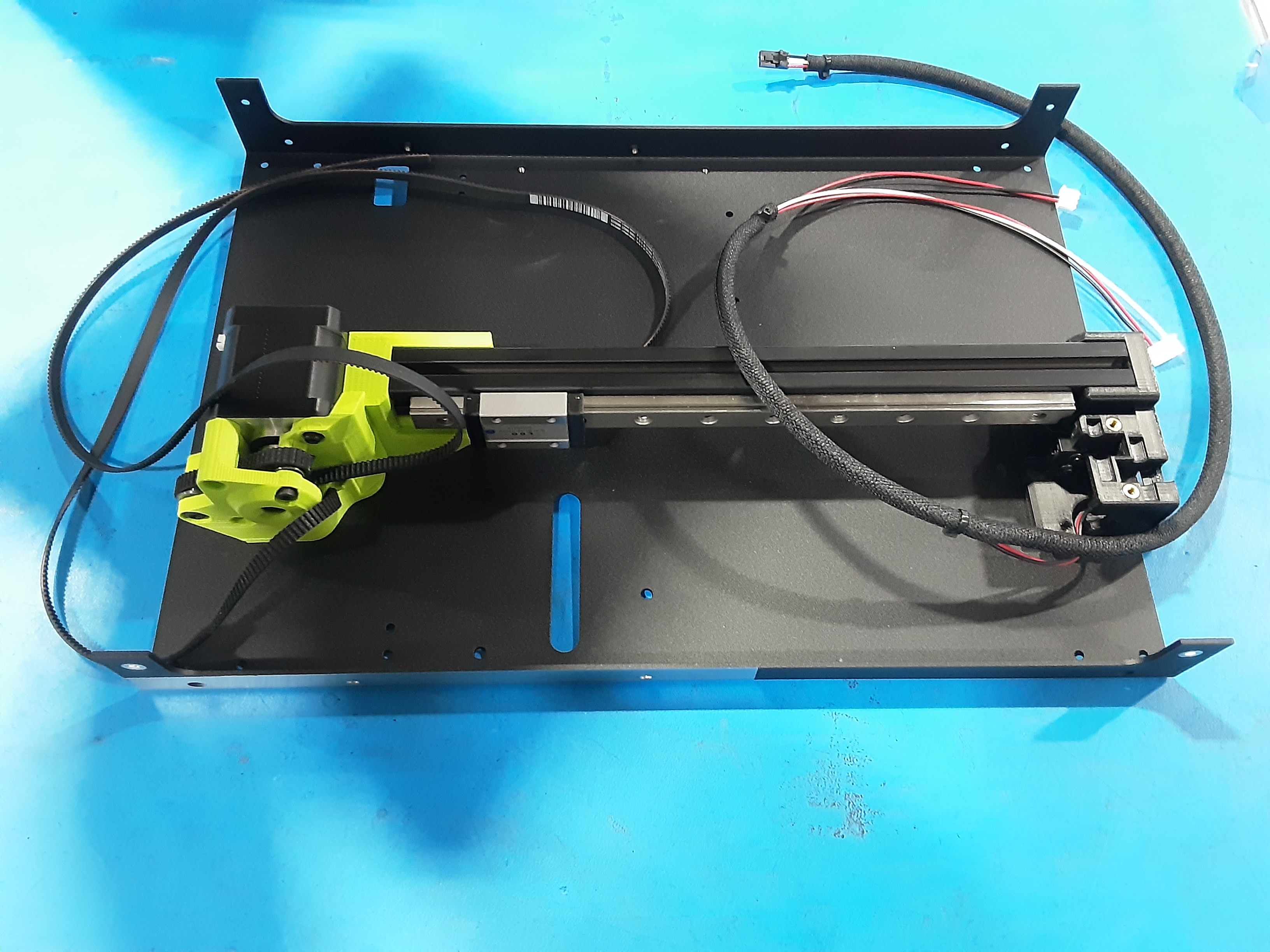
7A) Grab PP-FP0240 x1, HD-BT0128 x4, HD-BT0157 x4, HD-WA0038 x4, and Rail Assembly
7B) Lay the Rail Assembly on the table showing the inserts in PP-GP0809 and PP-GP0827.
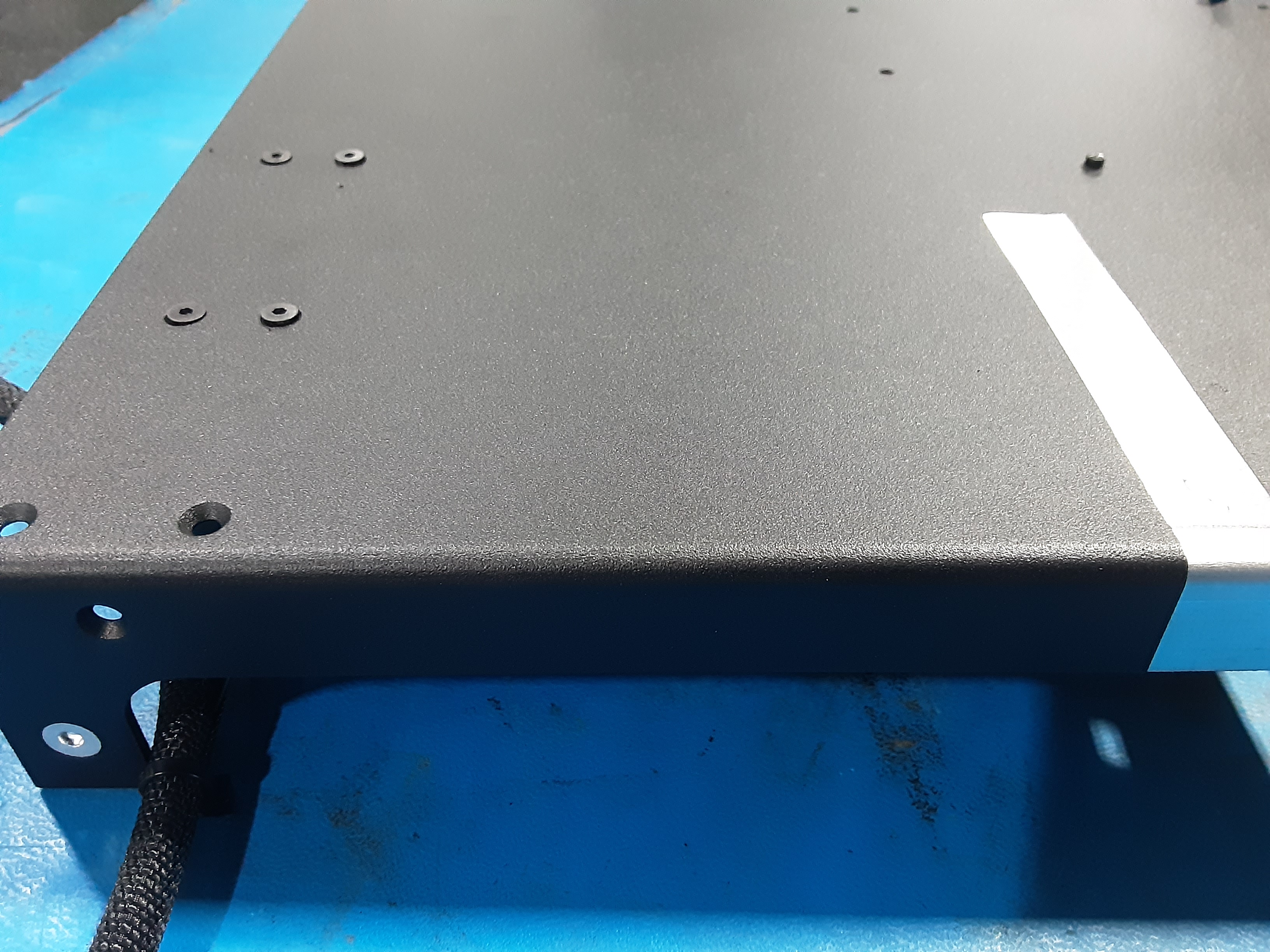
7C) Place PP-FP0240 onto the Rail Assembly lining up the holes with the inserts.
7D) Using HD-BT0128 x4 loosely attach PP-FP0240 to PP-GP0827.
7E) Using HD-BT0157 x4 and HD-WA0038 x4 loosely attach PP-FP0240 to PP-GP0809.
7F) With all HD-BT0128 and HD-BT0157 loosely in, can now tighten all screws.