Open HardwareAssembly Instructions
Guides for installation and assembly of the LulzBot line of products made by FAME 3D LLC.
Guides for installation and assembly of the LulzBot line of products made by FAME 3D LLC.
Follow the instructions below to quickly install your new Tool Head on a LulzBot TAZ Pro 3D Printer.
This guide will walk you through the process of installing the Twin Nebula Tool Head on a Pro S with a single extruder Tool Head installed.
If you are installing the Tool Head onto a TAZ Pro with a Dual Extruder already installed, please follow steps 1-8 of the TAZ Pro Tool Head installation guide for removing the Dual Extruder Tool head before returning to Step 9 of this guide.
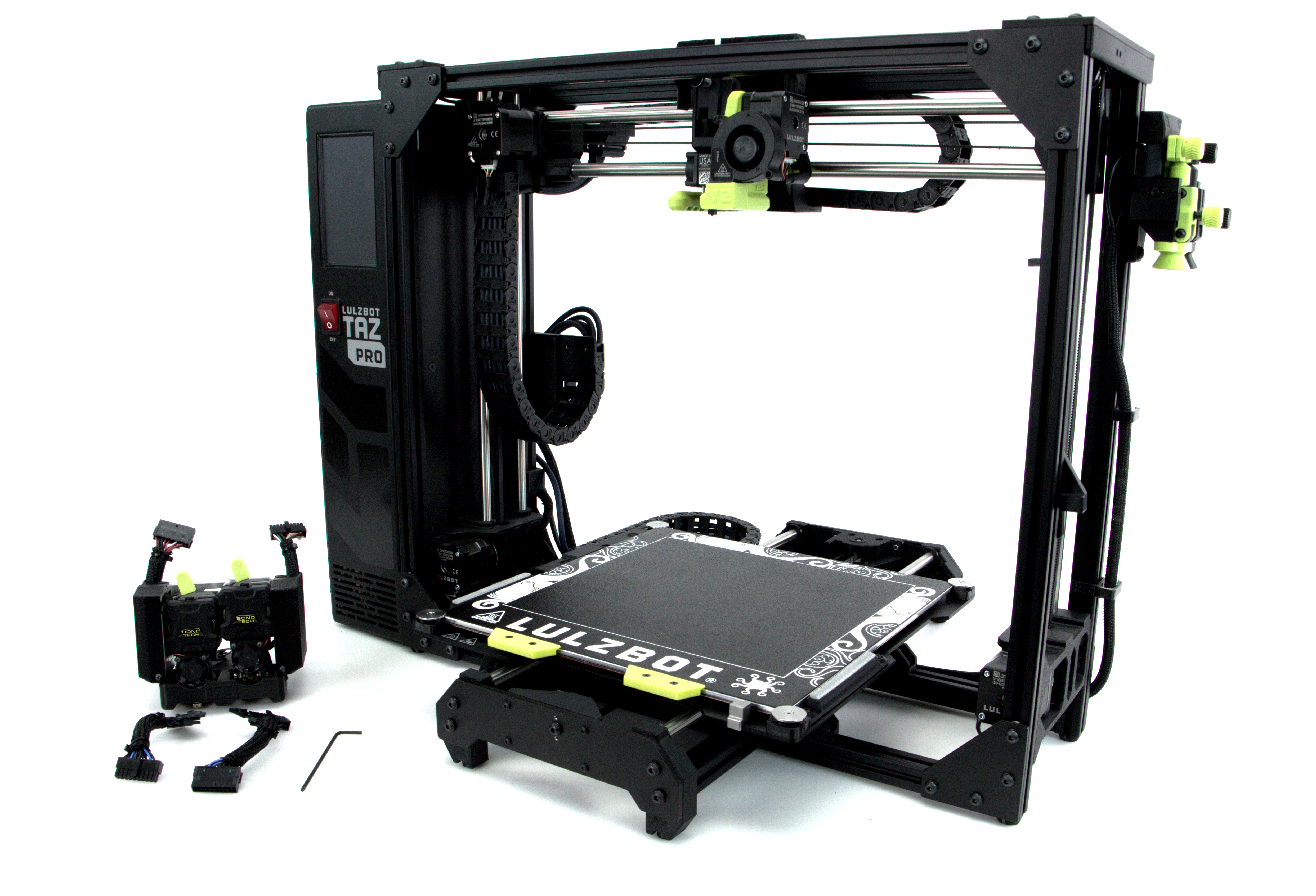
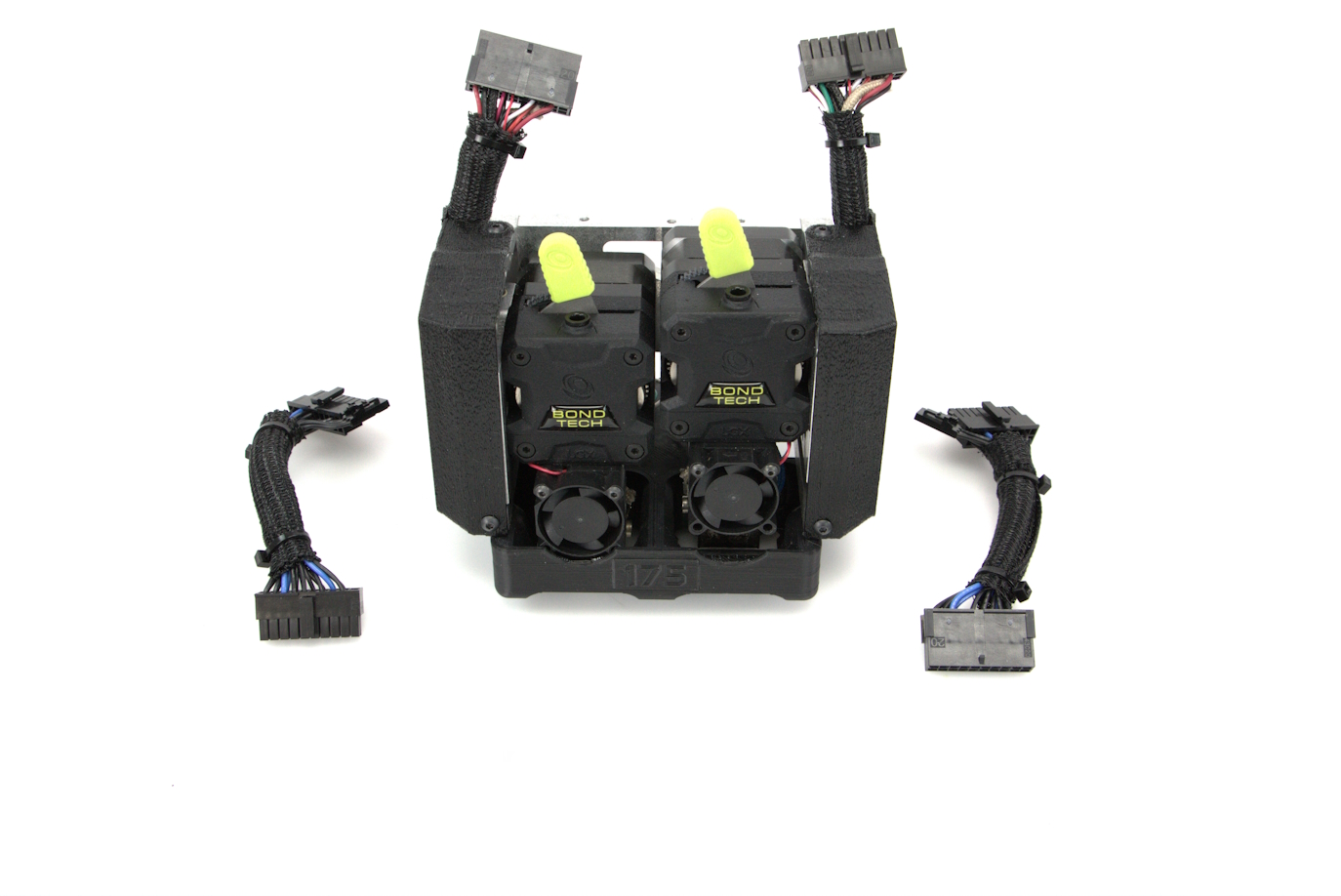
Included with the Twin Nebula Tool Head will be:
These feed tubes will be dependent on the diameter of compatible filament used in your Twin Nebula Tool Head. (1.75mm or 2.85mm)
You will also need
Power on the LulzBot TAZ Pro 3D Printer.
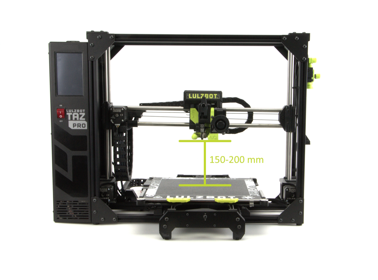
Home the 3D printer by using the LCD touch screen. Press Home All from the main window on the LCD.
Adjust the position of the Tool Head using the LCD touch screen menu so that is about 150-200 mm above the print bed and close to the middle of the X-axis.
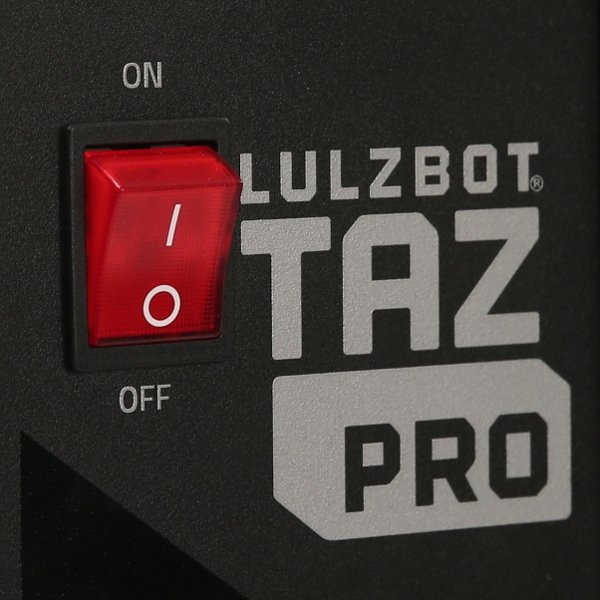
Once the Tool Head is position, turn the printer off.
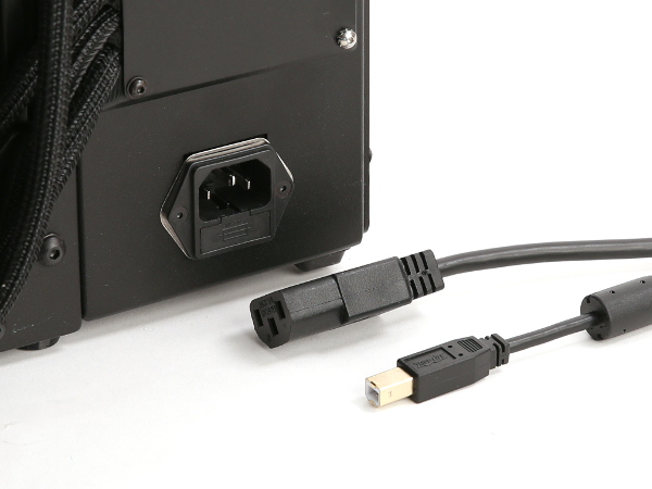
Unplug the AC power cable from the wall outlet, then unplug from the rear of the printer.
Unplug the USB cable (if installed).
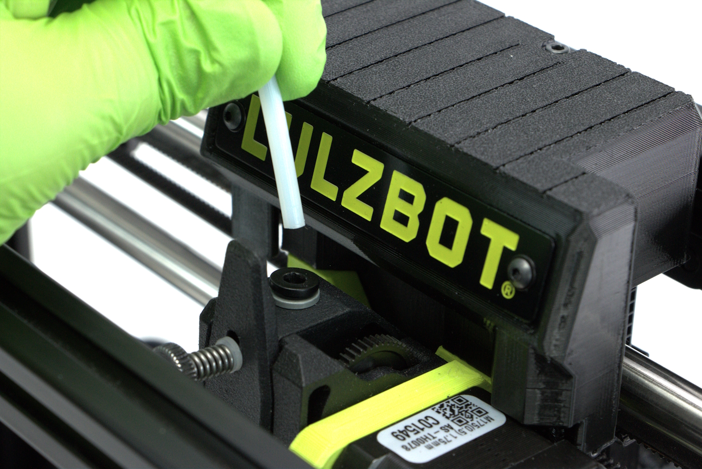
If the Tool Heads PTFE tube is still attached, remove from Tool Head.
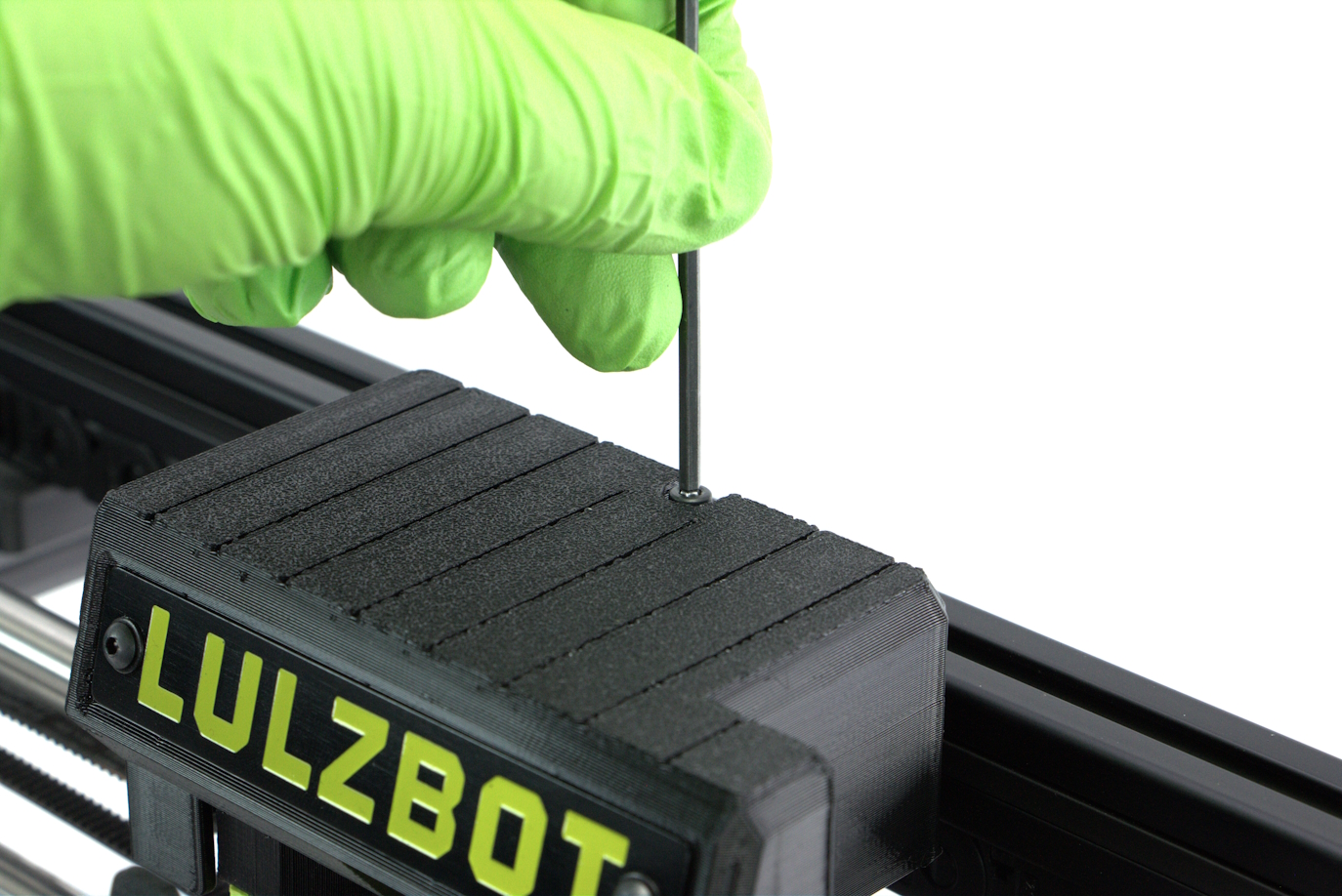
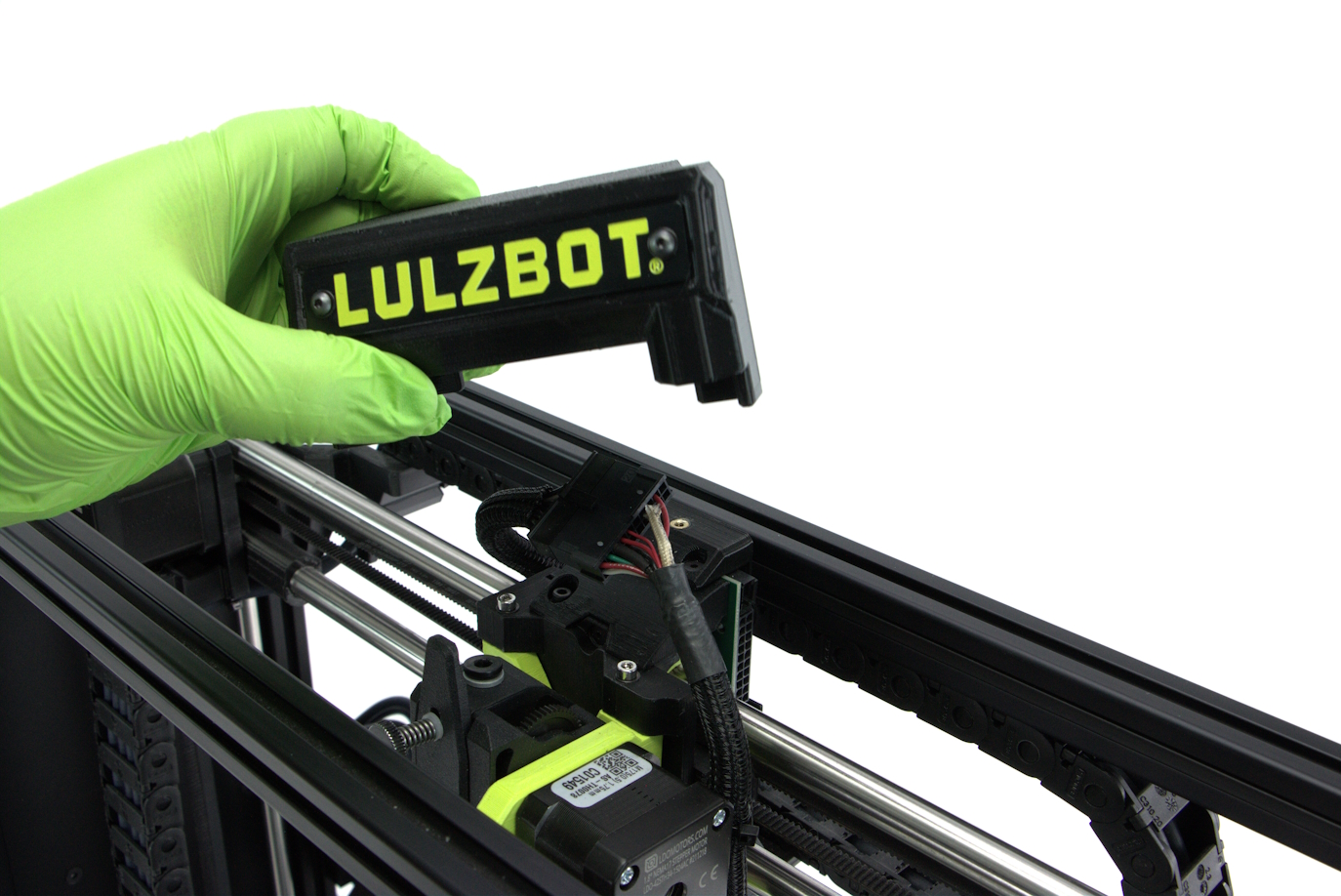
Locate and remove the single m3 on the top of the tool head cover. using the 2.5mm hex wrench.
Lift the Tool Head cover up and off of the tool head.
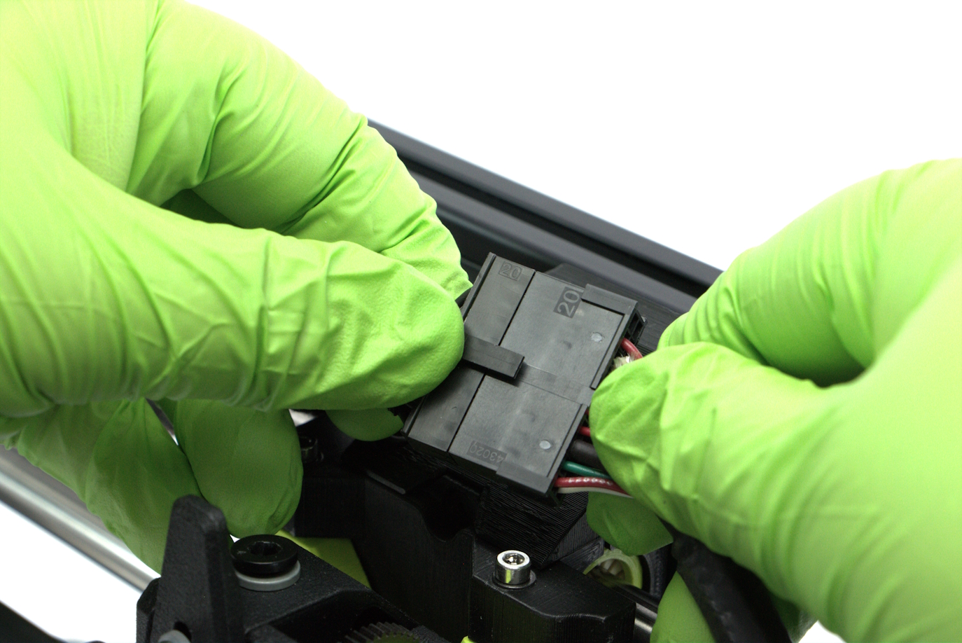
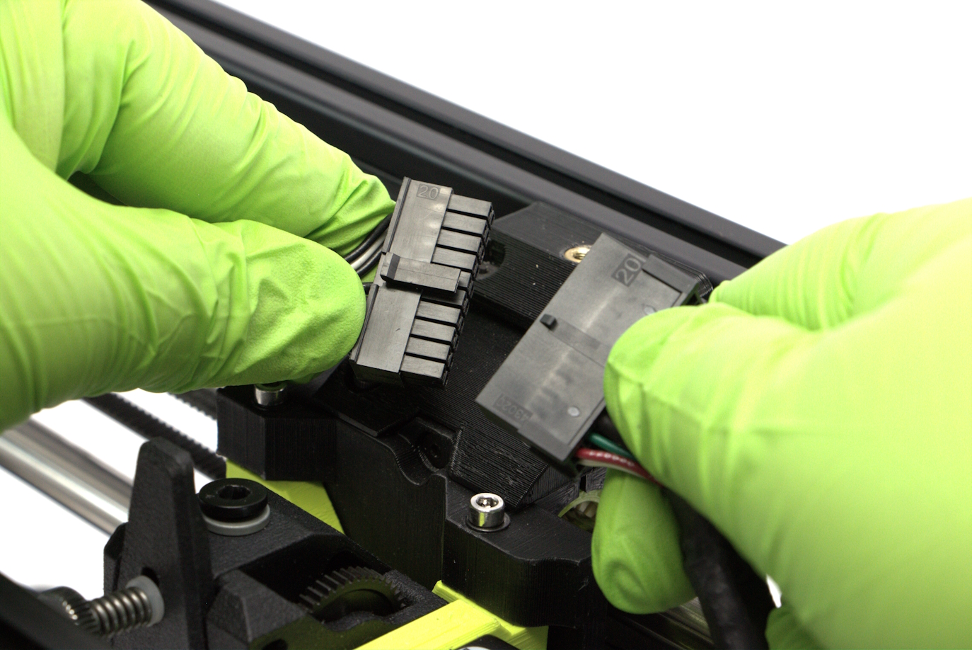
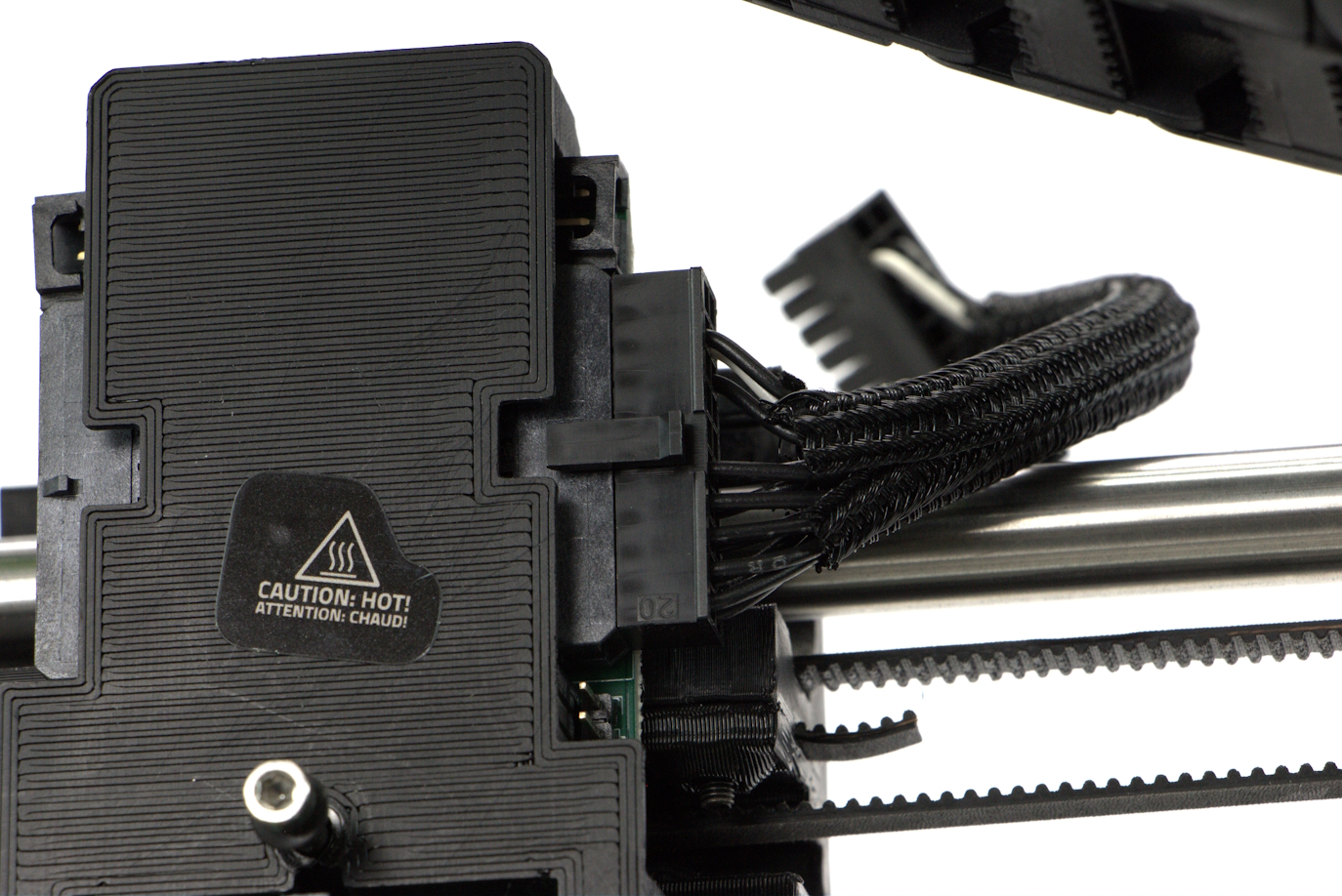
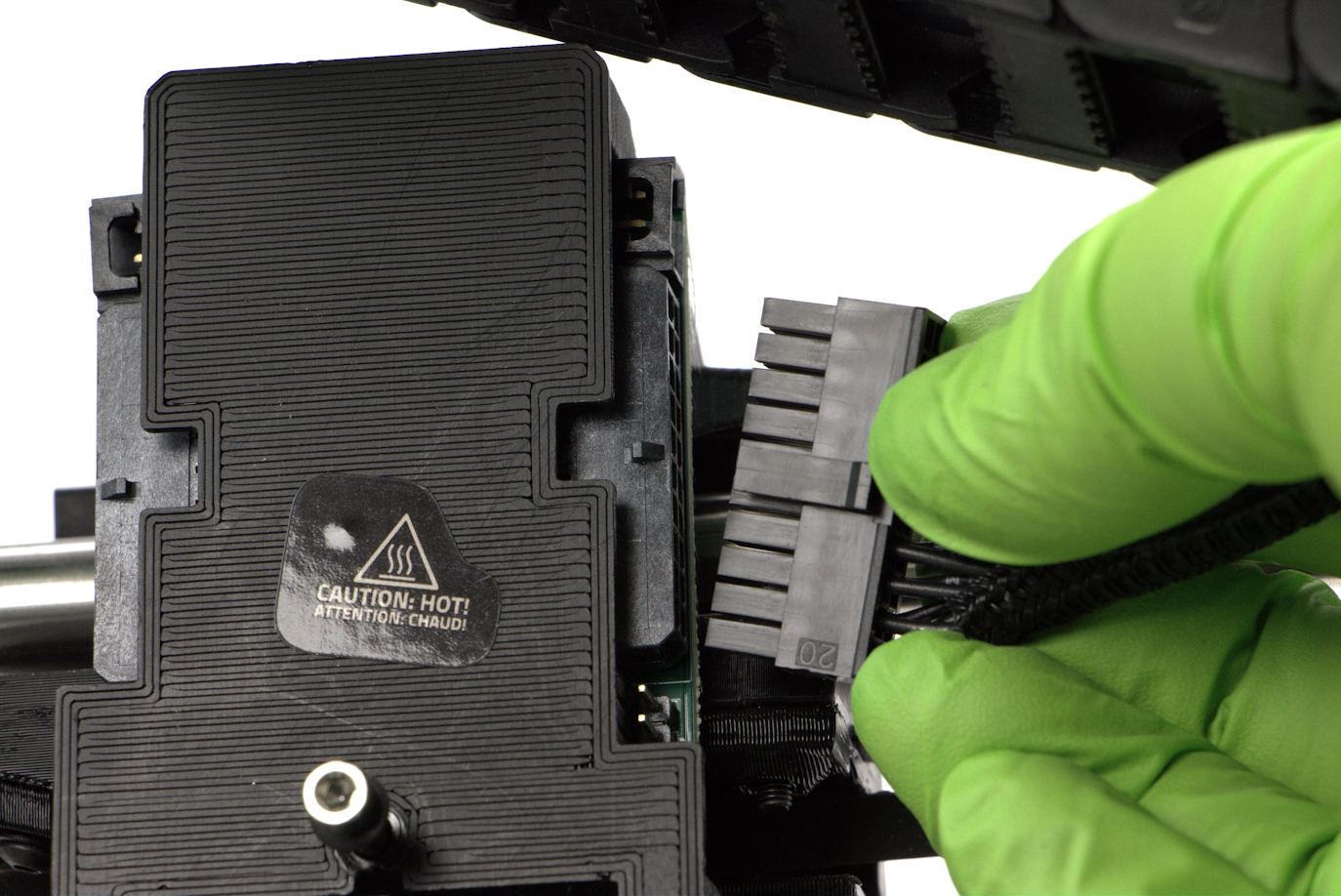
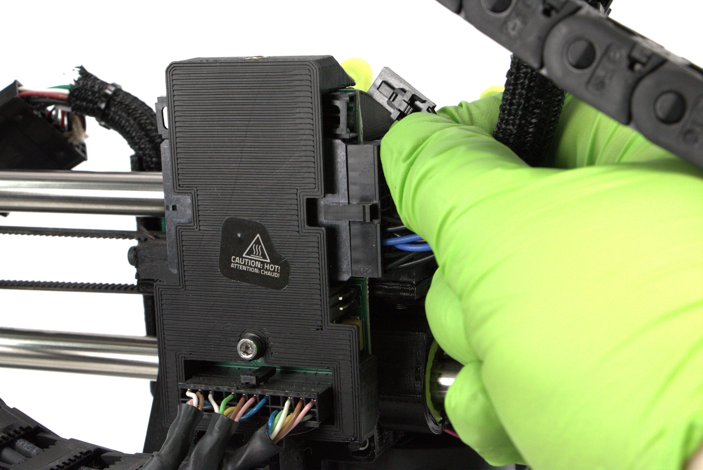
Locate the black connector above the Tool Head.
Depress the retaining clip and carefully pull the two halves apart.
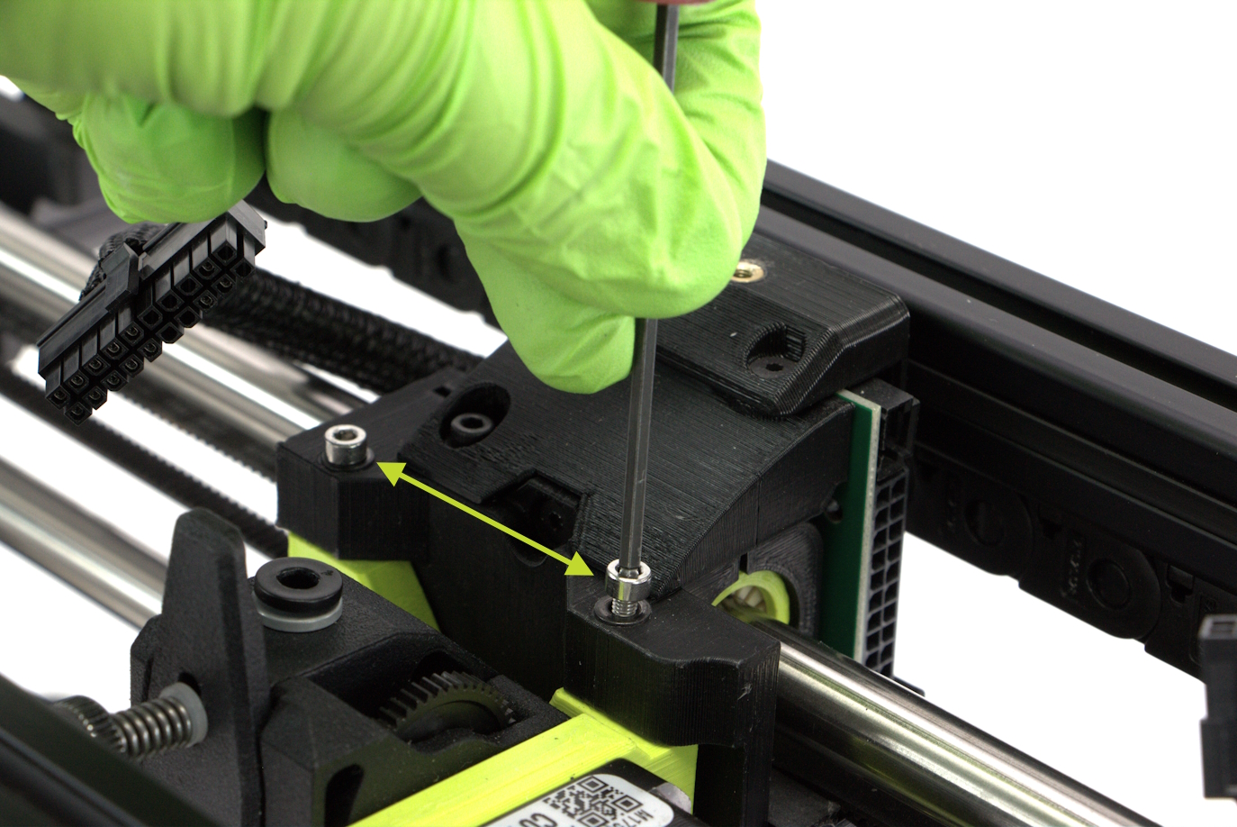
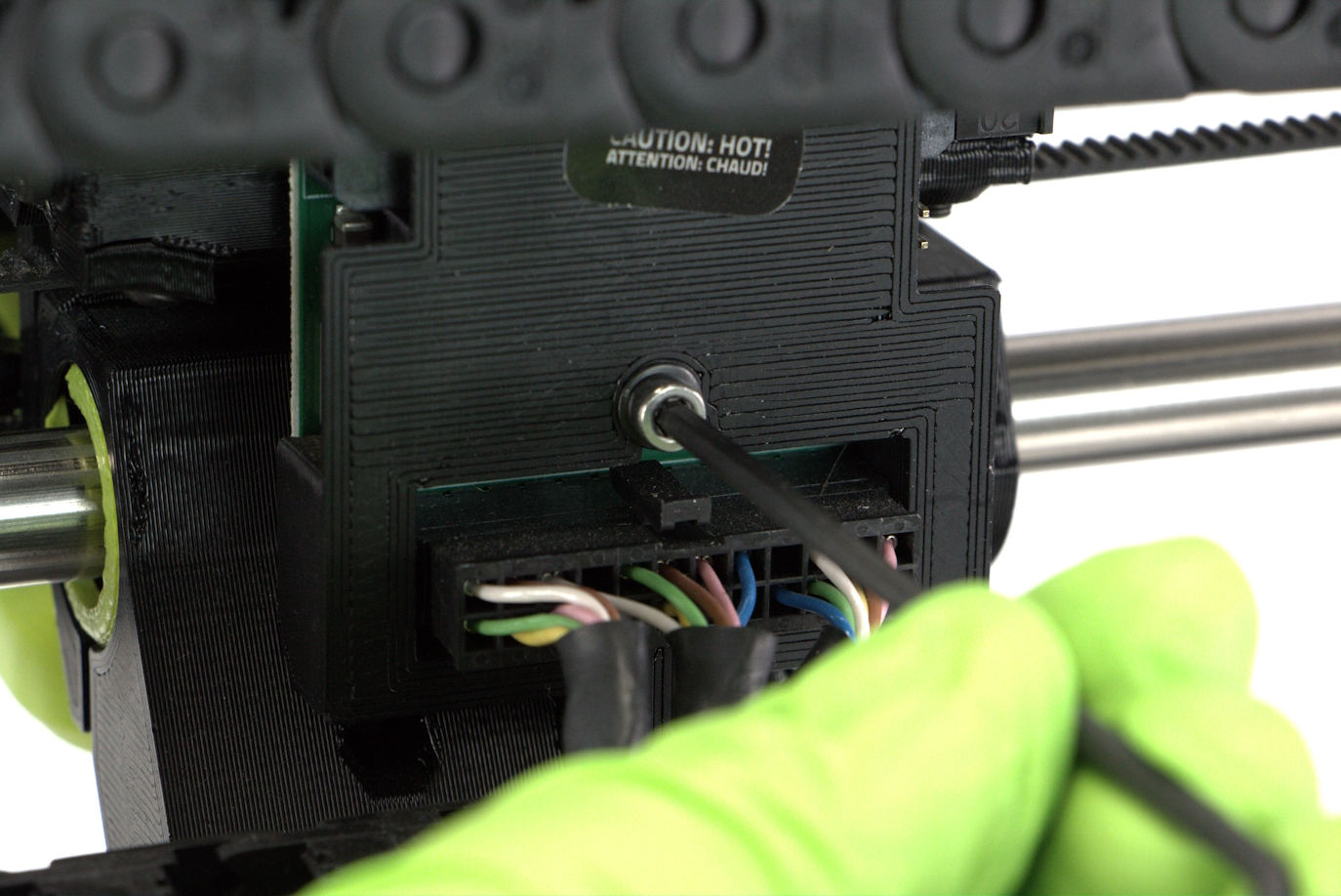
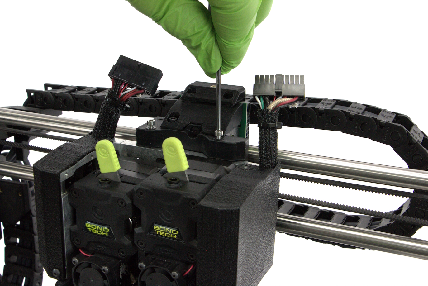
Using the 2.5mm hex wrench, remove the two stainless steel m3 screws that are located above the Tool Head.
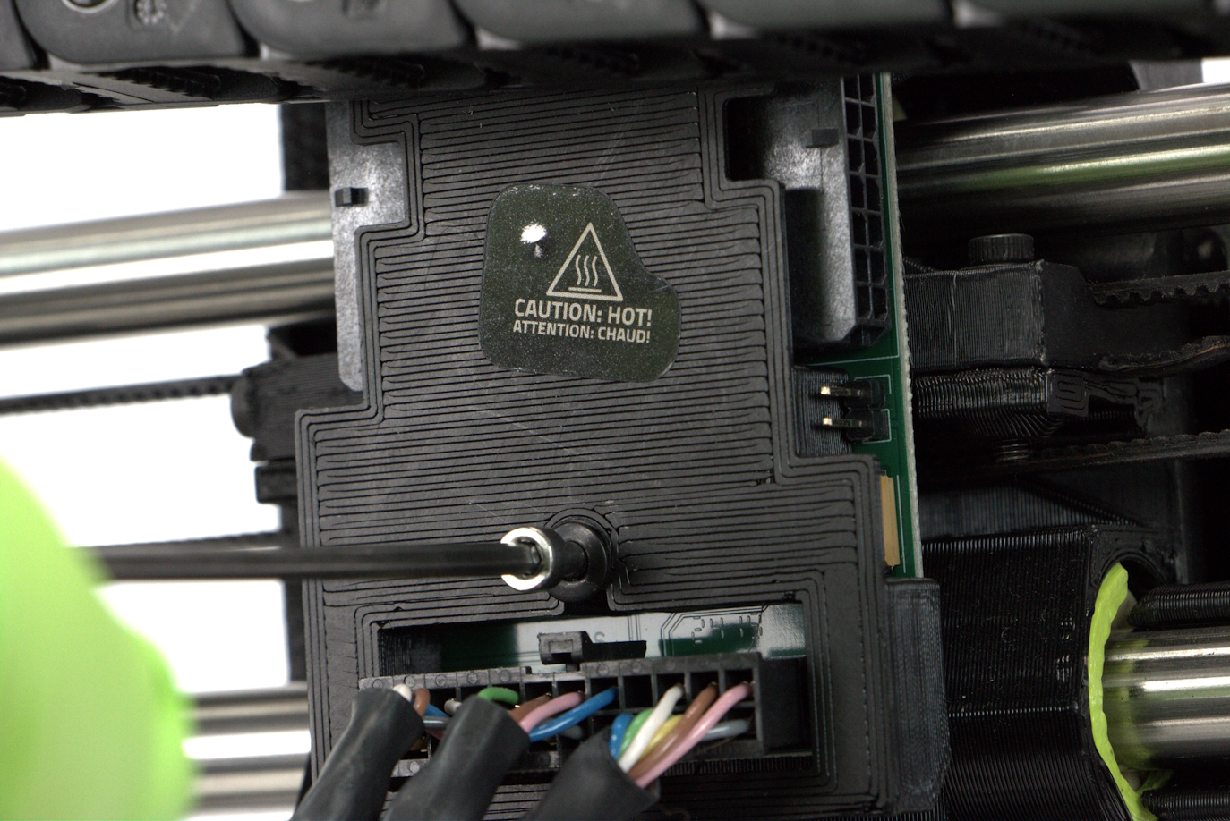
Turn the printer around and locate the stainless steel screw at the back of the x-carriage.
Support the Tool Head with your hand and unscrew the rear m3 screw using the 2.5mm hex wrench.
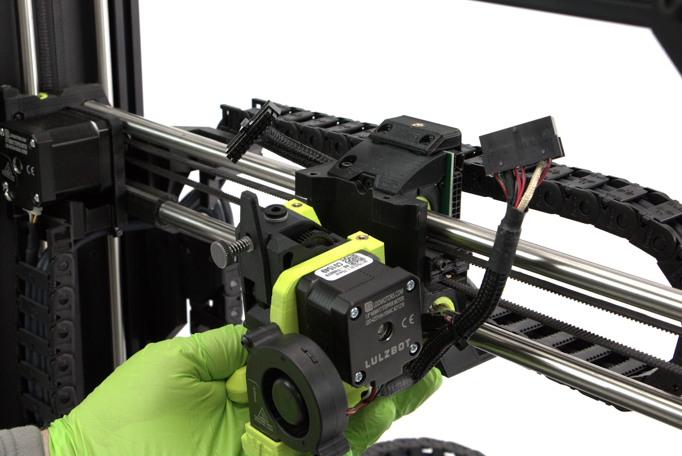
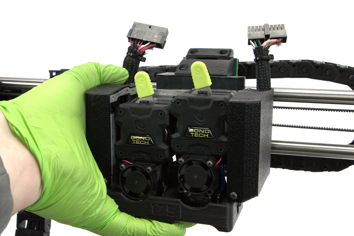
Move the Tool Head away from the printer and place someplace safe.
Remove the e1 extension harness from back of the x-carriage and set aside.
Hold new Tool Head in place while screwing in both top Tool Head mounting screws loosely using the 2.5 mm hex key.
Do not tighten completely.
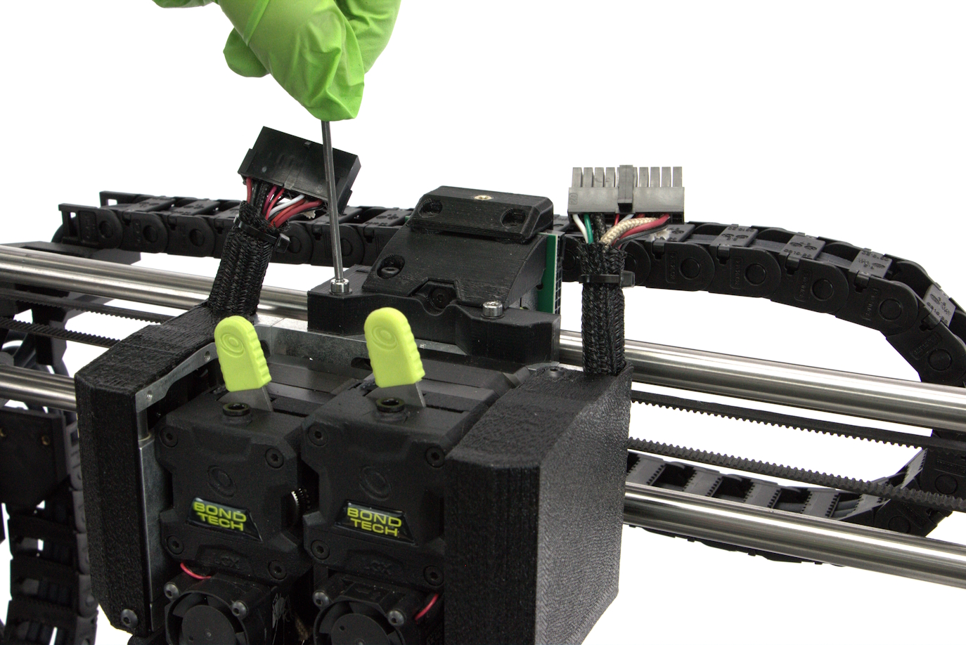
While still supporting the Tool Head, screw in the tool head mounting screw completely on the back of the X-axis carriage using the 2.5 mm hex key.
Tighten down the two Tool Head mounting screws
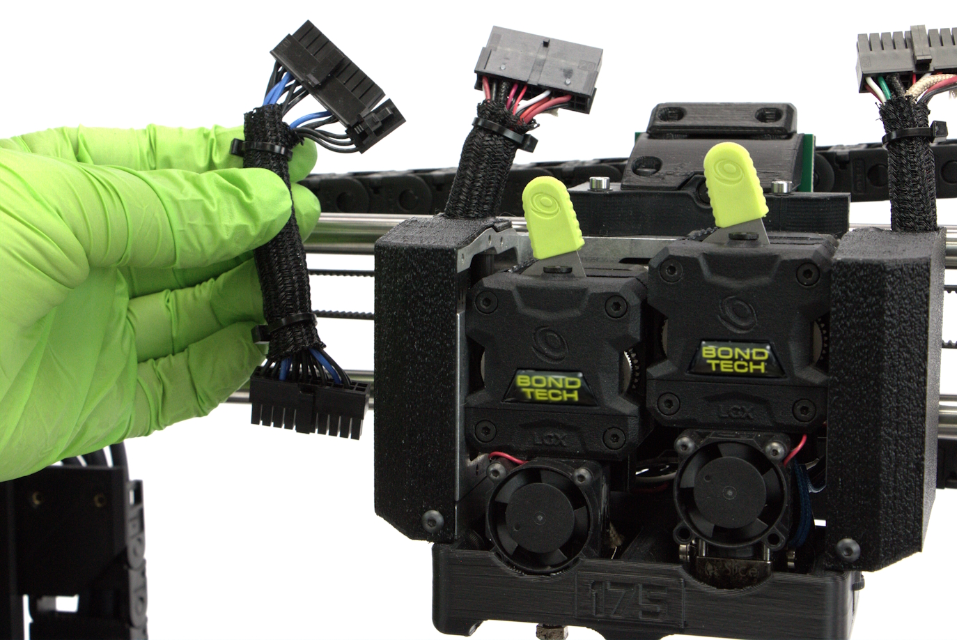
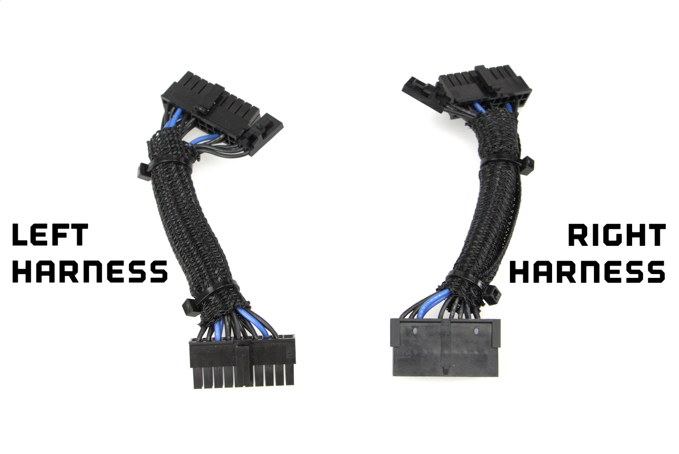
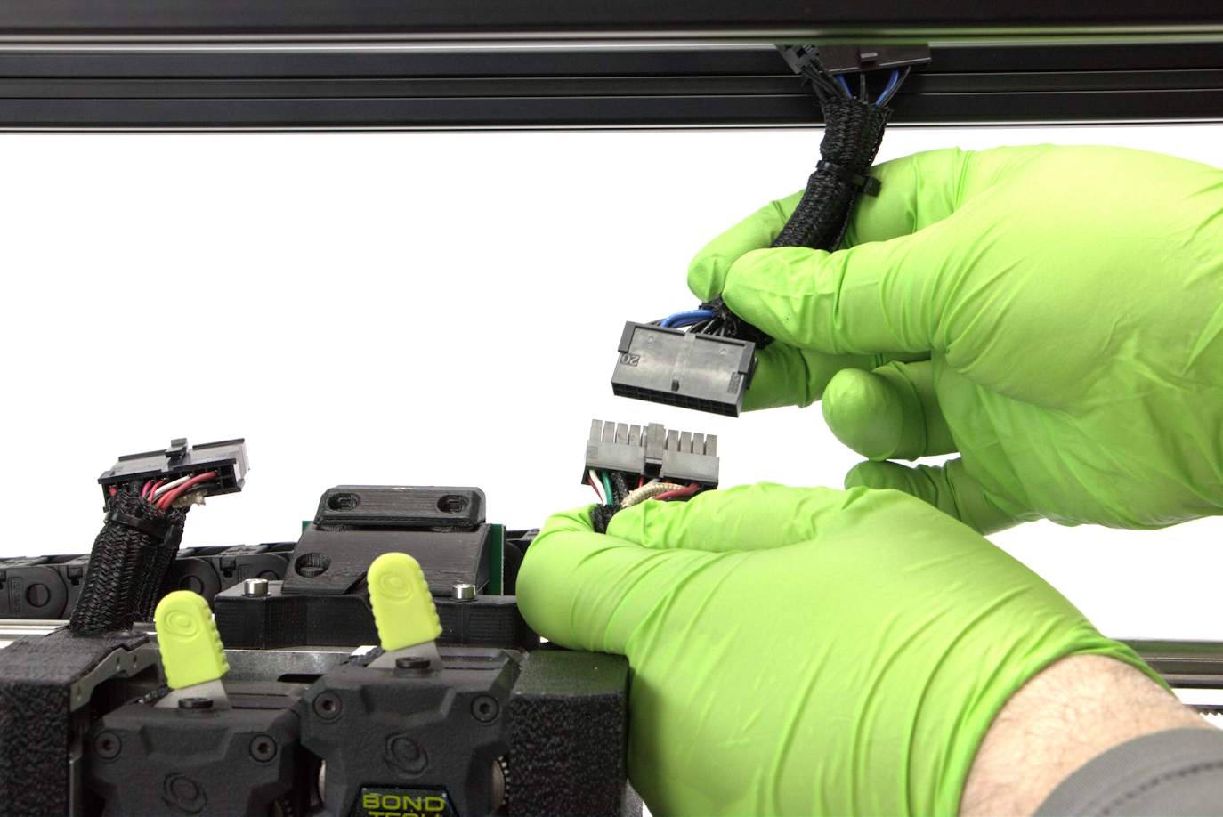
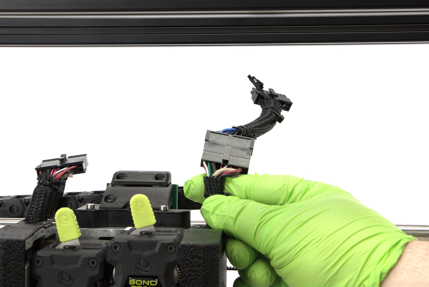
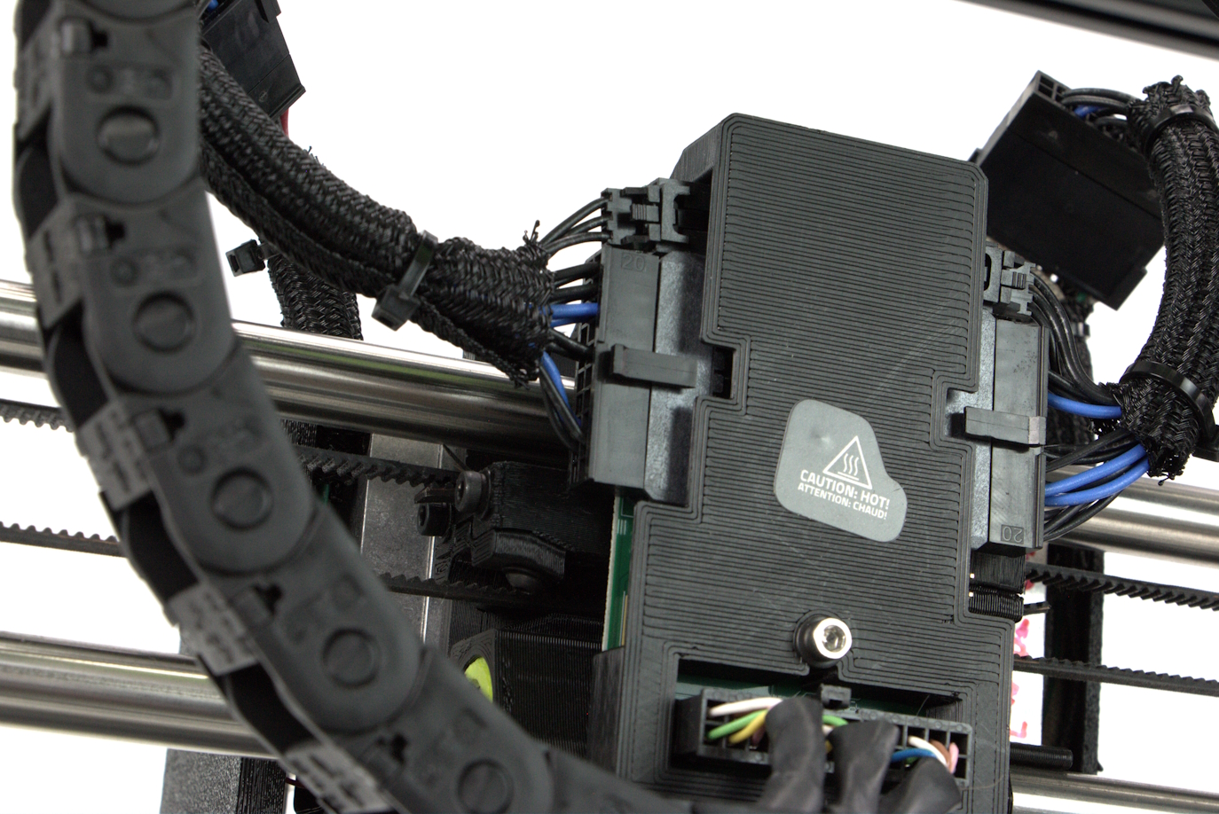
Locate the left harness extension. One side of the extension will have 1 connector, and the opposite side will have 2 connectors.
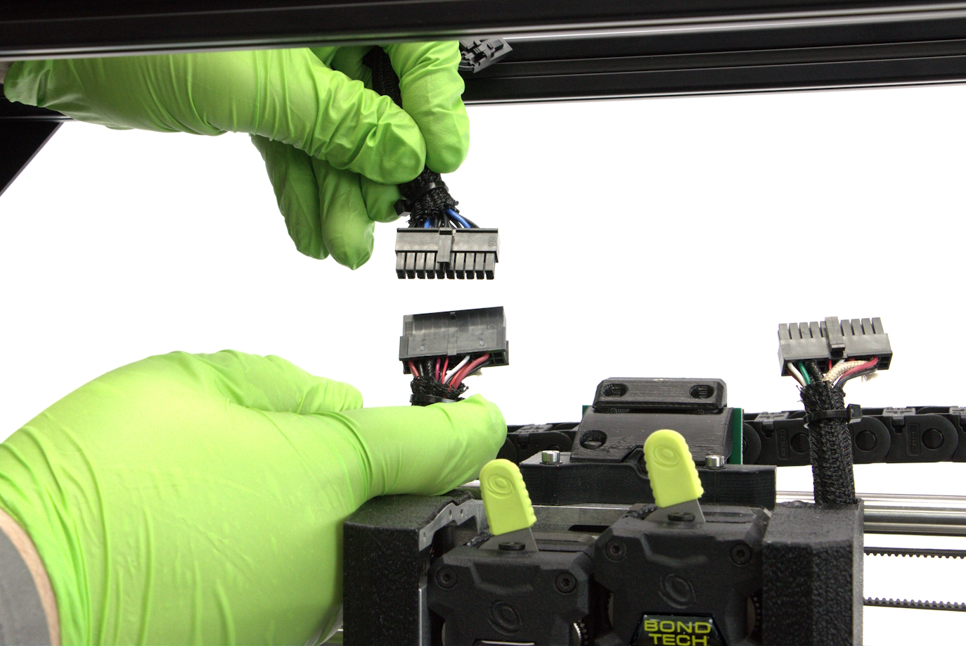
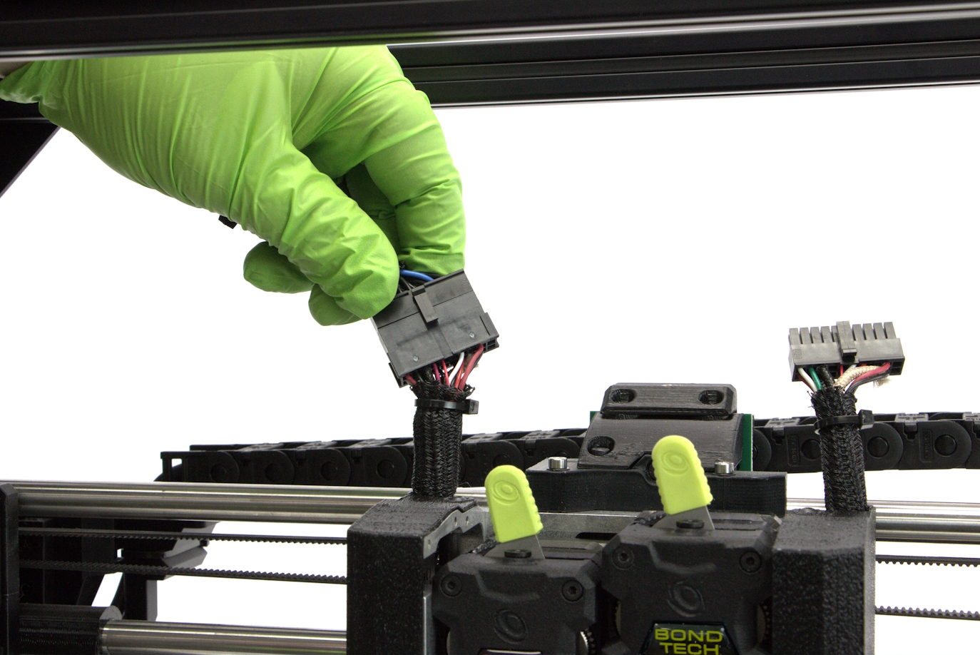
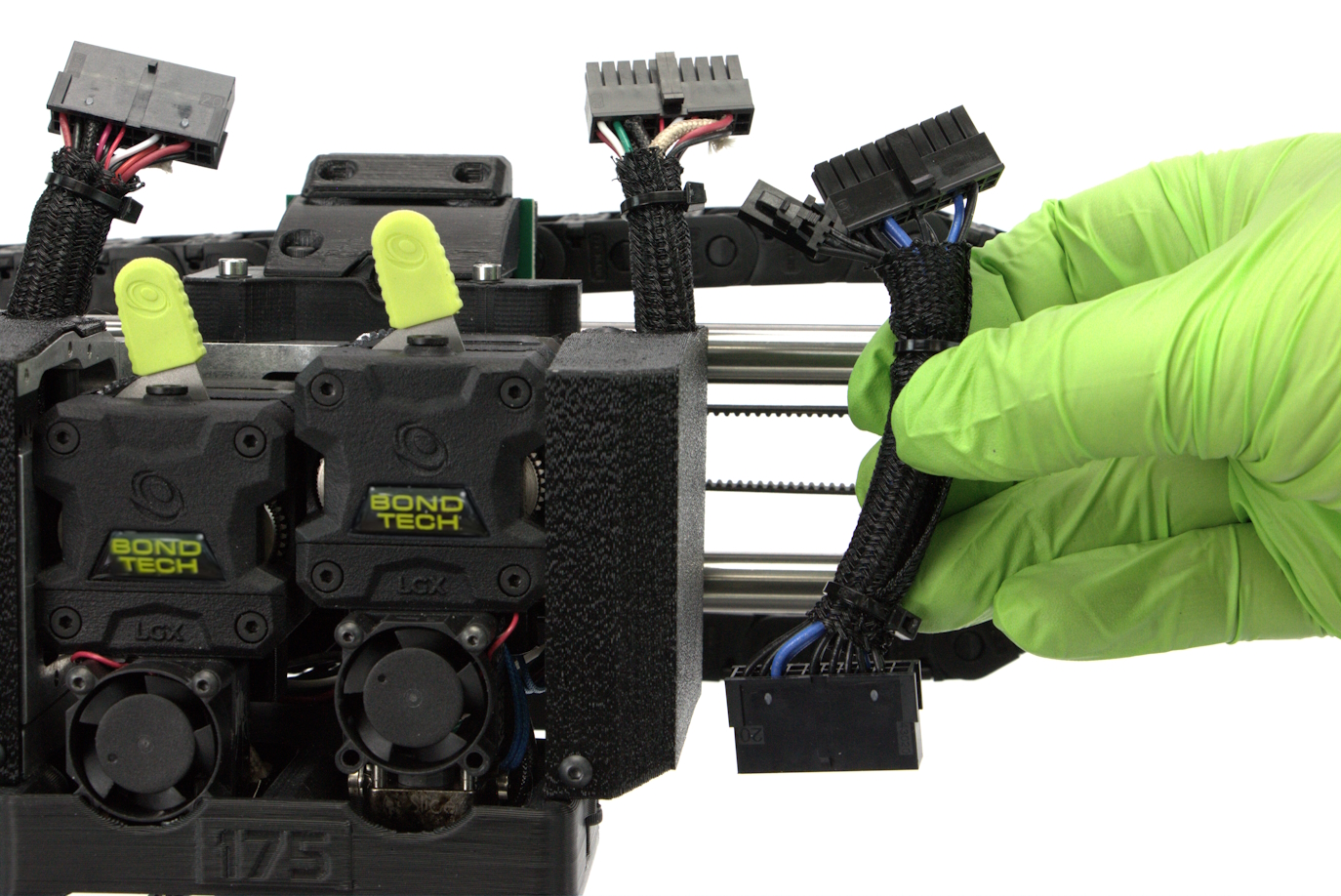
Carefully plug in the single connect side of the extension into the left harness that comes from the Tool Head.
Do not force the connector. place the halves together and gently wiggle the connectors to seat all of the pins.
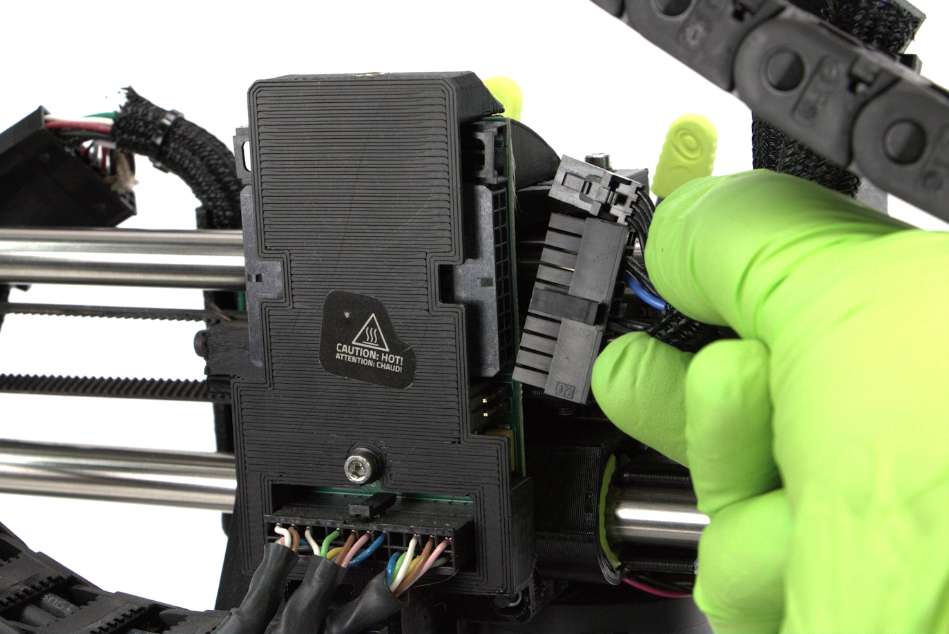
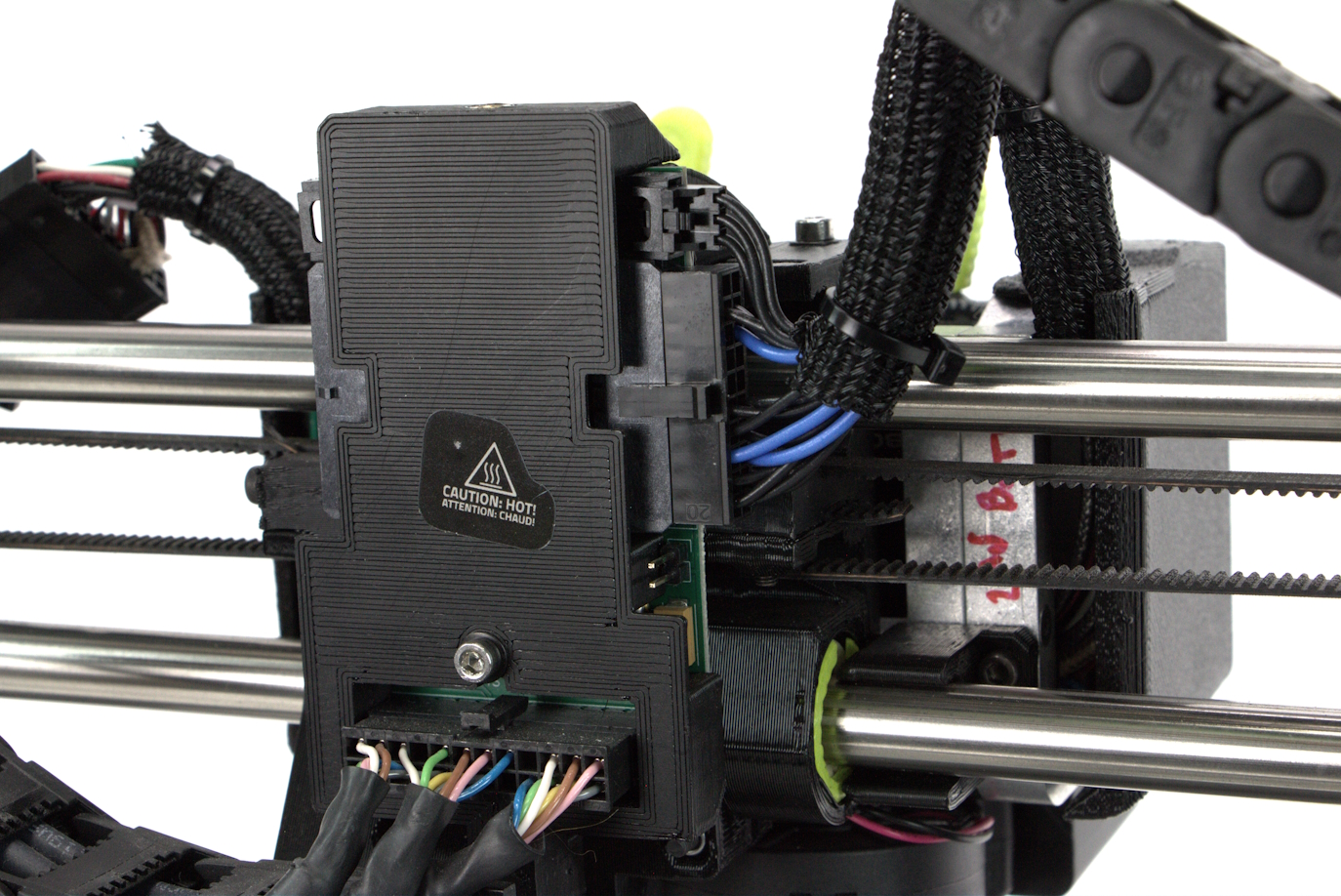
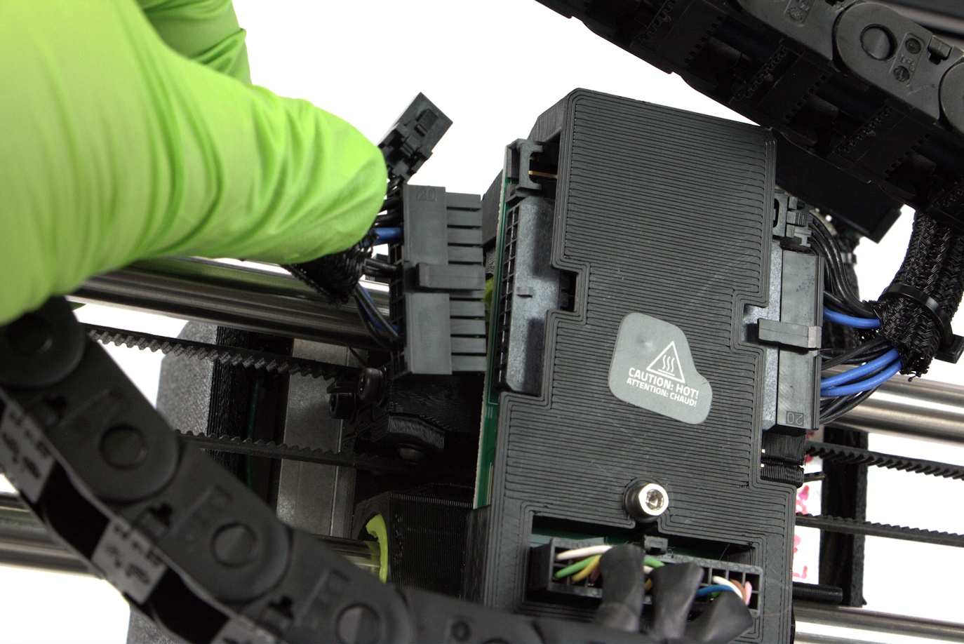
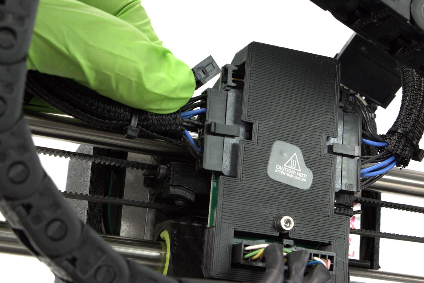
Turn the printer around and locate the opposite side of the extension harness and plug the larger connector into the back of the x-carriage.
Plug the smaller connector into the x-carriage directly above the large connector.

Locate the right harness extension. One side of the extension will have 1 connector, and the opposite side will have 2 connectors.
Carefully plug in the single connect side of the extension into the right harness that comes from the Tool Head.
Do not force the connector. place the halves together and gently wiggle the connectors to seat all of the pins.
Turn the printer around and locate the opposite side of the extension harness and plug the larger connector into the back of the x-carriage.
Plug the smaller connector into the x-carriage directly above the large connector.
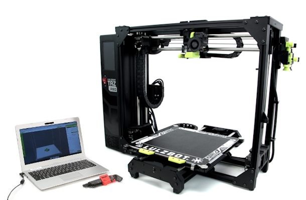
Install the latest version of Cura LulzBot Edition. It is important to have the LulzBot Edition of Cura, as it has preset machine configuration profiles built into it.
The Twin Nebula is only compatible with Cura LulzBot Edition version 4.13.9+.
Go to LulzBot.com/Cura to install Cura LulzBot Edition.
Plug in your LulzBot TAZ Pro 3D printer to the power supply and power on your 3D printer.
Once powered on, connect your 3D printer to your computer using the USB cable.
Open Cura LulzBot Edition.
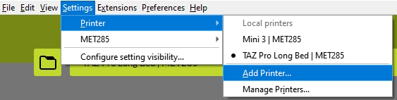
Select Settings dropdown > Printer > Add Printer
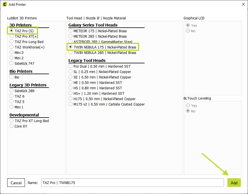
Select LulzBot TAZ Pro (S) in the first column, then the appropriate Twin Nebula Tool Head in the second column, and click Add Printer.
Select Add.
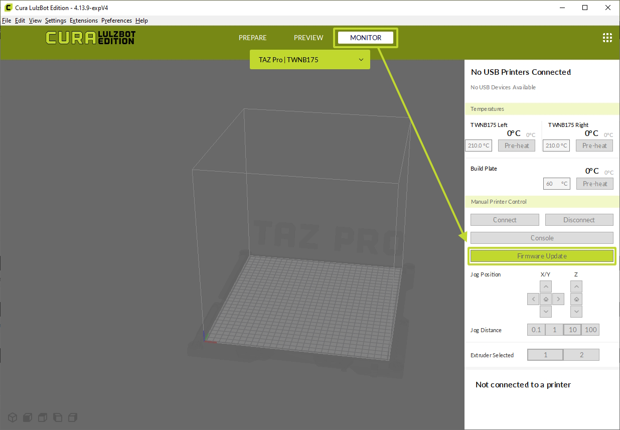
Select Monitor from the Cura LE main page.
Click Firmware Update on the right side of the window.
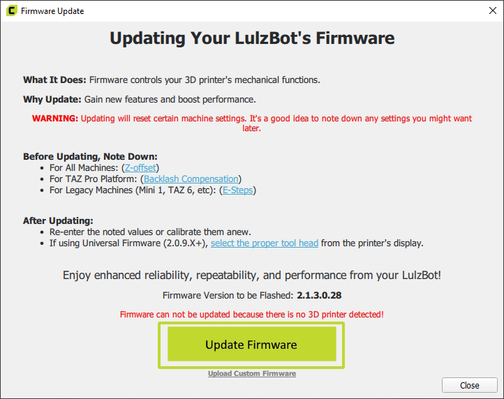
Select Update Firmware.
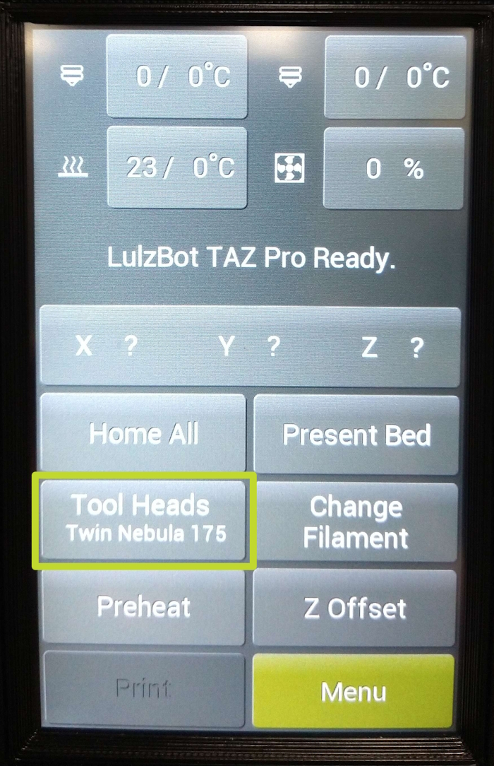
If installing the Twin Nebula 285, you will need to select the correct Tool Head via the printers LCD.
Navigate to the first menu screen on your printers LCD and select the Tool Heads menu.
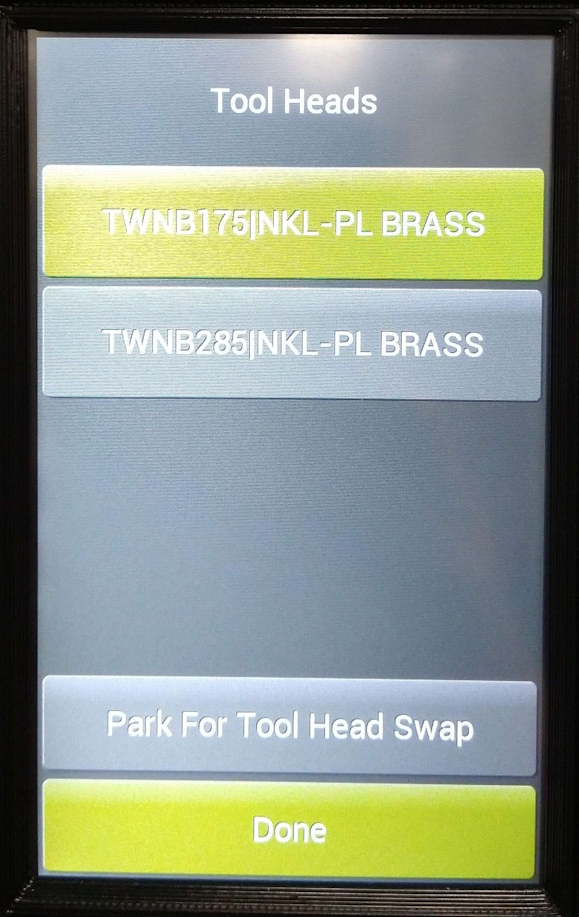
Locate the Twin Nebula 285 Tool Head and select it.
Heat the Tool Head up to extrusion temperature via the printers LCD or through Cura.
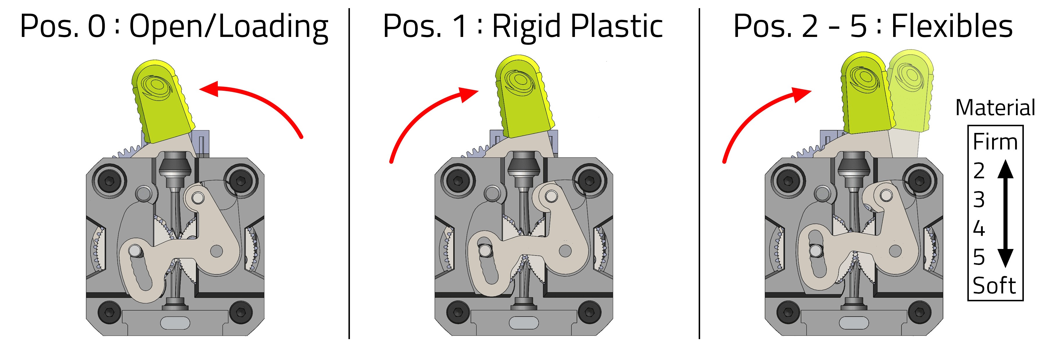
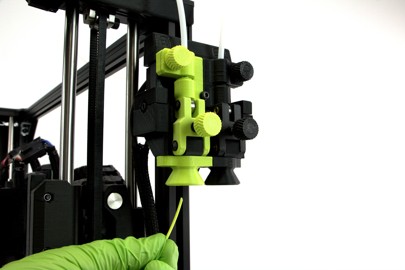
Once the Tool Head reaches the appropriate filament temperature, Push the filament tension lever to the left.
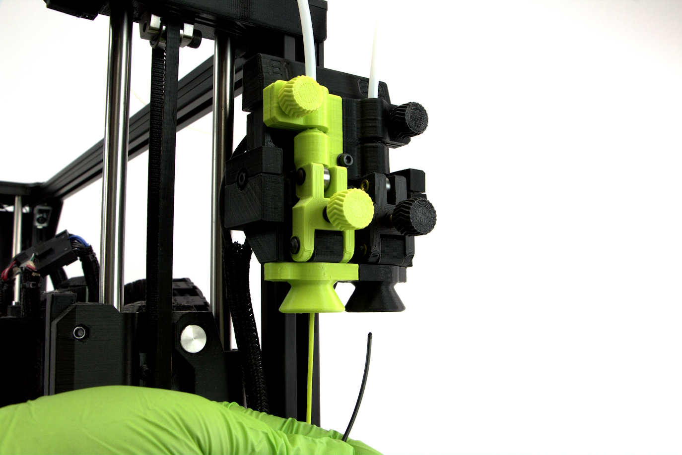
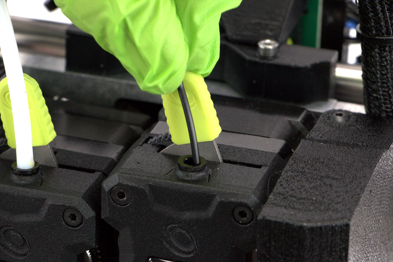
Start by inserting filament into the runout sensor and feeding it all the way through the PTFE guide tube.
Straighten the filament slightly and begin feeding the filament into the extruder.
Move the tensioning lever 1 position to the right to engage the gears onto the filament.
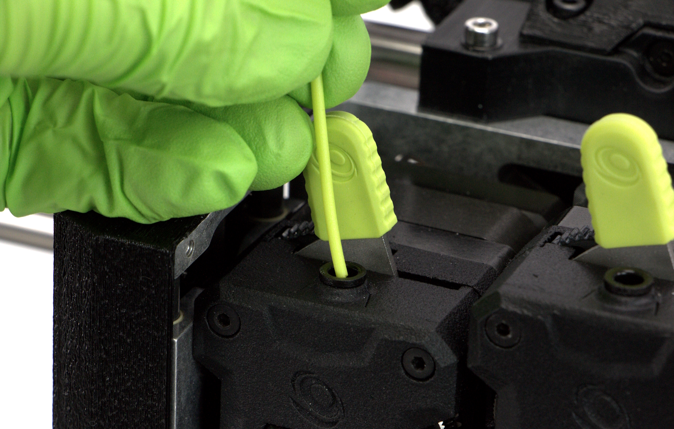
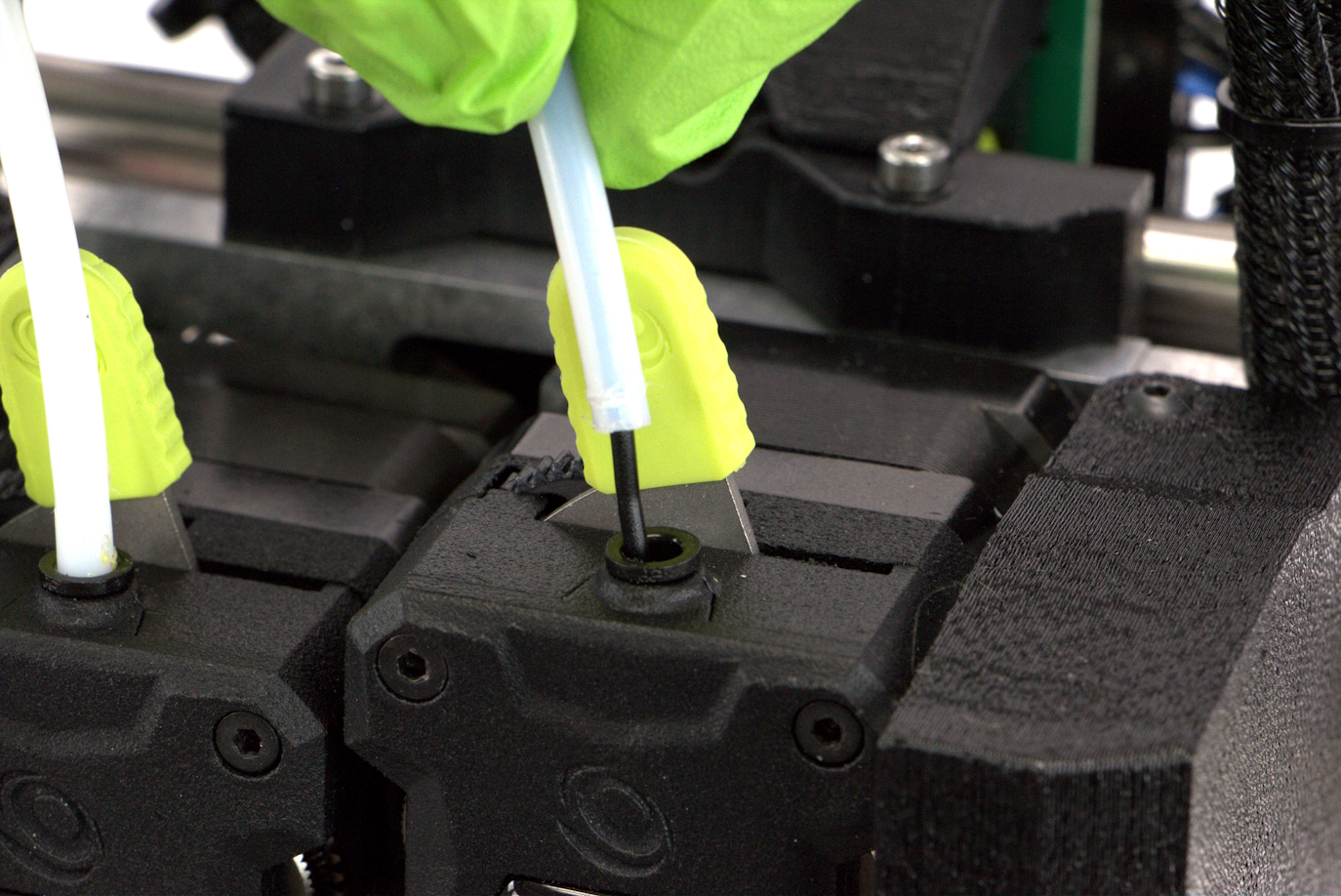
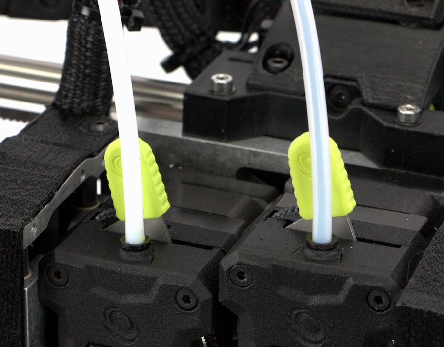
Push down the PTFE guide tubes to lock them into the extruders.
NOTE
In order for the runout sensor to function correctly, the filament inserted into the green side of the sensor MUST be routed into the left side extruder on the Tool Head. Failure to route the filament from a specific side of the runout sensor to the correct side of the Tool Head will result in filament extrusion errors.
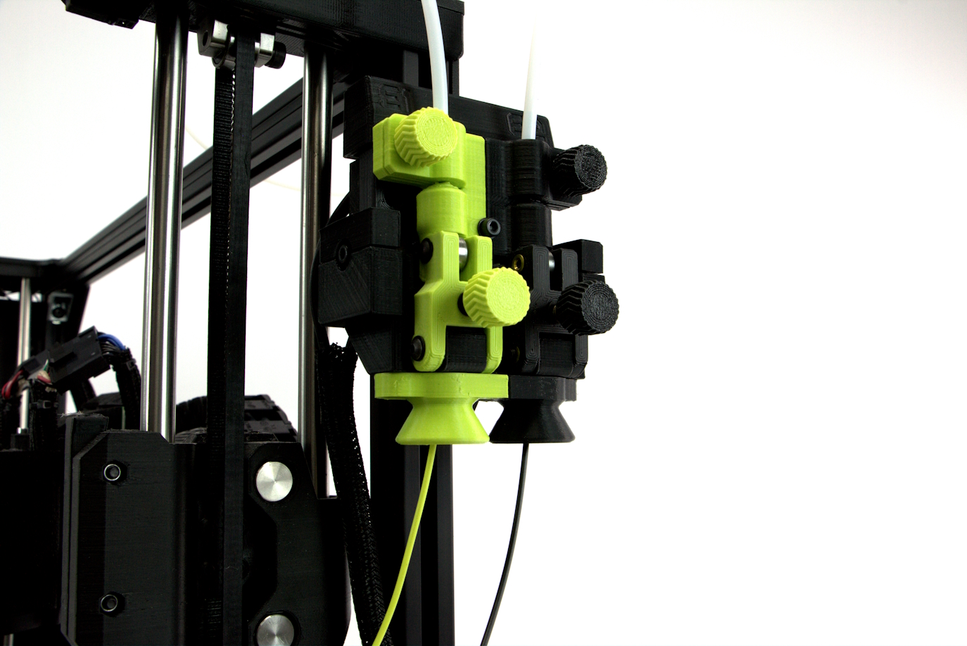
You've now finished installation and are ready to start printing!
Try performing a test print!
If you encounter issues please contact Technical Support by emailing Support@LulzBot.com, or by calling +1-701-809-0800.