Open HardwareAssembly Instructions
Guides for installation and assembly of the LulzBot line of products made by FAME 3D LLC.
Guides for installation and assembly of the LulzBot line of products made by FAME 3D LLC.
Tools needed:
M3 Ball Hex Driver
M3 Hex Driver
M4 Ball Hex Driver
Hardware and assemblies needed:
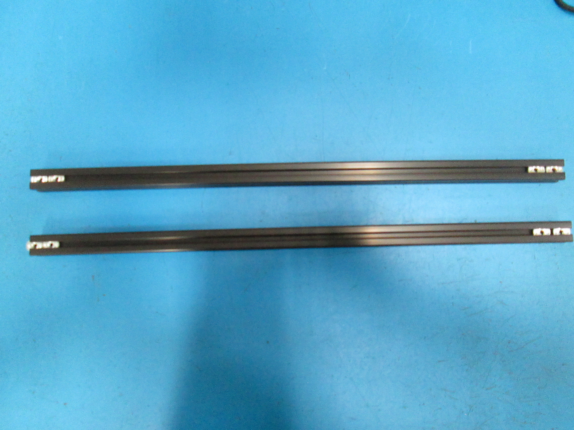
4 x 500mm Single tap Extrusion Bars (HD-EX0063)
4 x 510mm No tap Extrusion Bars (HD-EX0061)
54 x T-nuts (HD-NT0053)
1 x Spring T-nut (HD-NT0044)
58 x Black Oxide M5 Washers (HD-WA0040)
2 x M5x14 SHCS Black Oxide (HD-BT0049)
56 x M5x10 BHCS Black Oxide (HD-BT0073)
2 x 608 Bearings (HD-MS0282)
2 x Z-uppers (PP-GP0236)
1 x Spool Arm (AS-PR0012)
4 x Bed Mount Chassis (AS-PR0008)
1 x Tippy Feed Tube Holder (AS-PR0011)
1 x Z-axis Right (AS-PR0017)
1 x Z-axis Left (AS-PR0013)
8 x Frame corner (PP-MP0106)

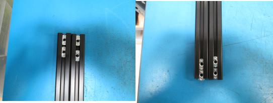
Start by taking two of the single tap extrusion bars (HD-EX0063) place them vertically with the tapped hole facing the top, then put two t-nuts (HD-NT0053) in the top and bottom of the bar.
Next take two of the no tap extrusion bars (HD-EX0061) perpendicular to the single tapped bars.
Place one t-nut on both sides of each extrusion bar, then with your hands on the end of the bar rotate the bar 90 degrees forward.
Next place two t-nuts on both sides of the extrusion bars.

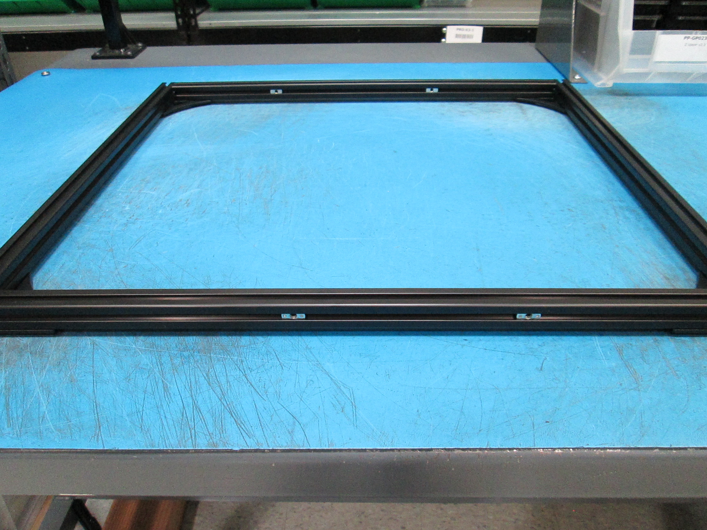
Front Frame:
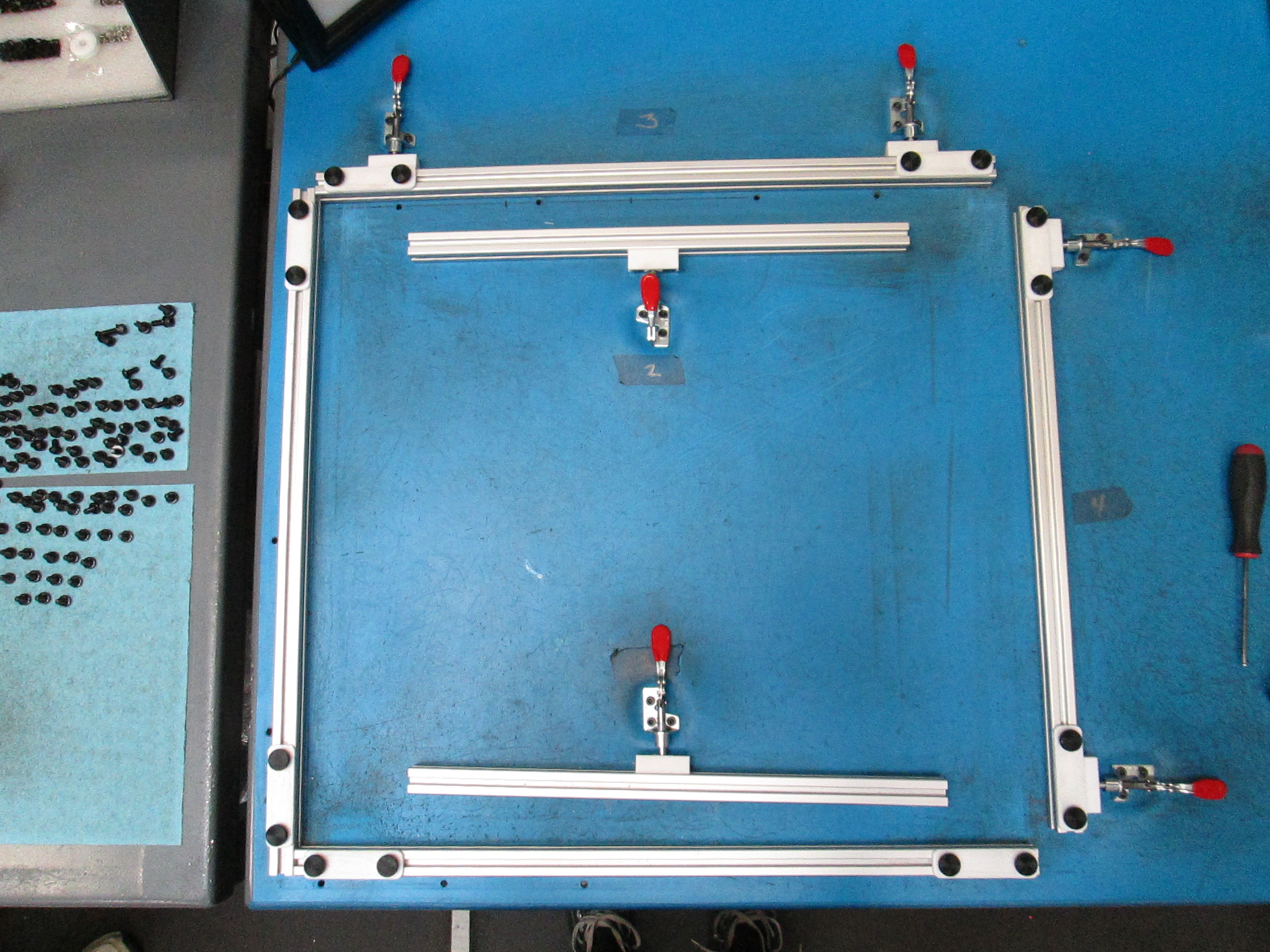
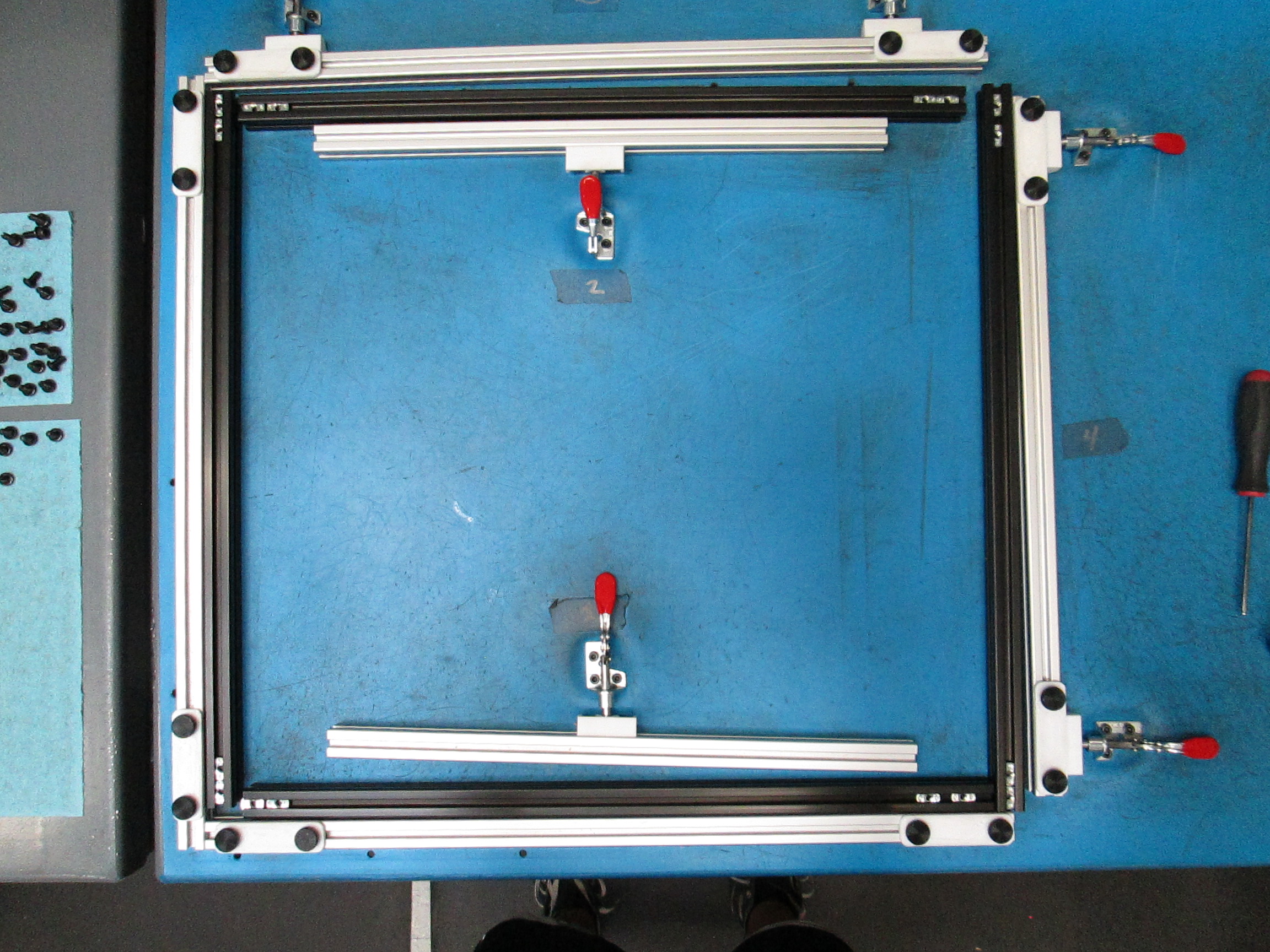
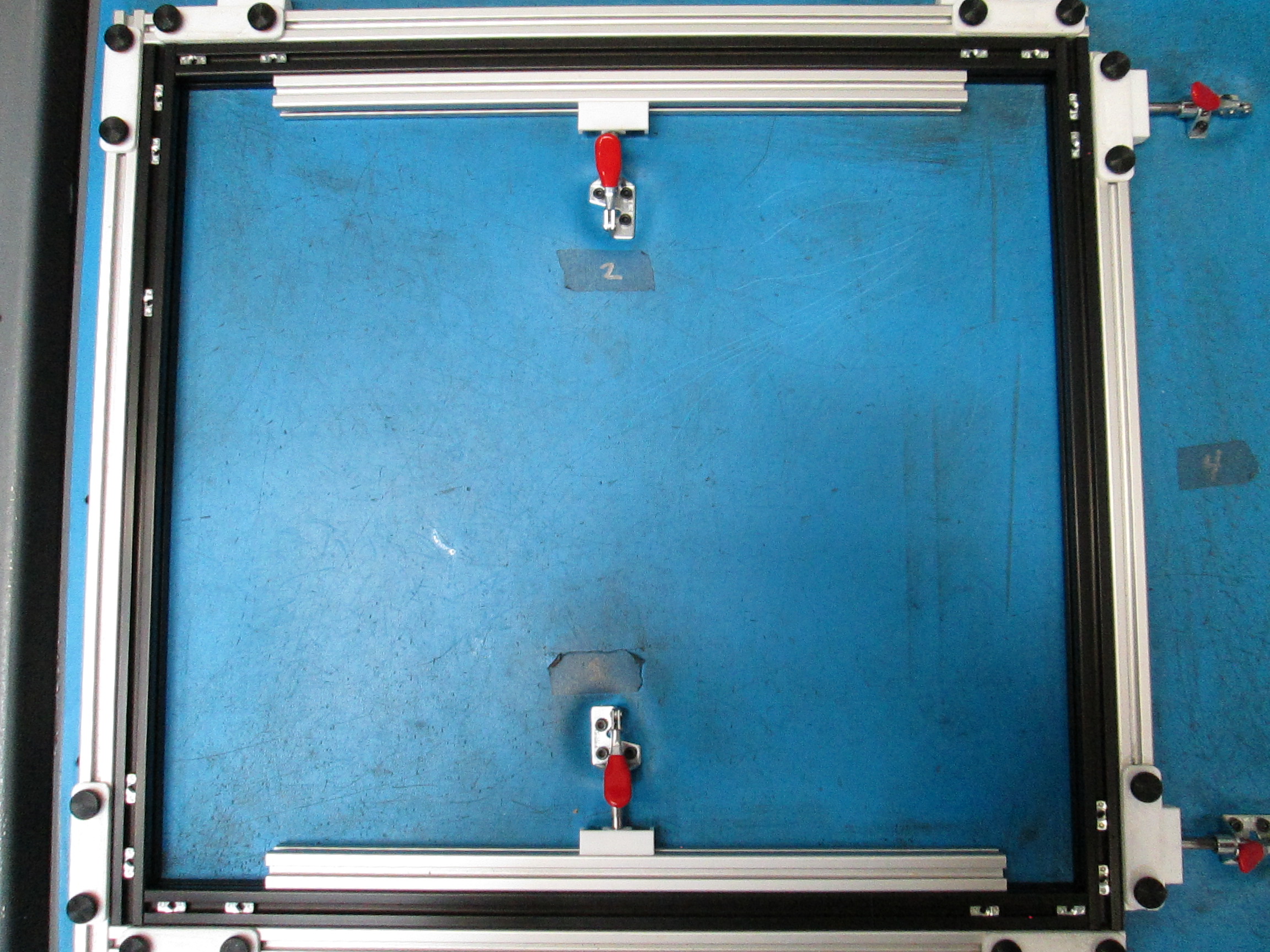
Now we will take all four bars and place them into the frame squaring jig.
Place the single tap extrusion bar on the left and right side of the jig with the tapped hole facing the top of the jig, place the no tap extrusion bars between the single tap bars at the top and bottom of the jig.
Make sure that the bars have two t-nuts in each corner so we can attach the frame corners and clamp the frame into the jig. This will hold the frame square so we can tighten the frame corners down.
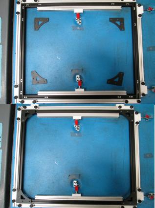
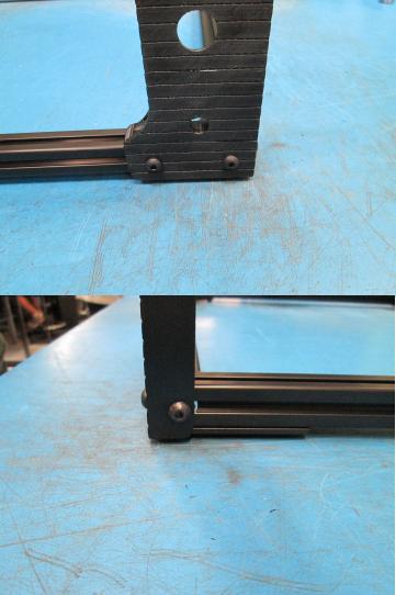
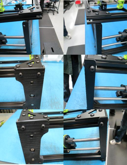
Place a frame corner (PP-MP0106) in each corner of the clamped frame.
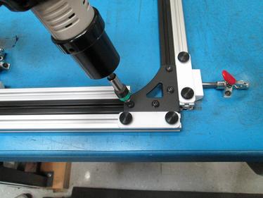
Using four M5x10 BHCS (HD-BT0073) with M5 black oxide washers (HD-WA0040) tighten/torque the frame corners to 40 in*lbs.
Make sure the frame corners are flush with the corners of the jig and the drill bit is fully seated in the screw head before torquing the corners down.
If corners are not flush the frame will not square properly and if the bit is not fully seated into the screw head the head could become stripped.
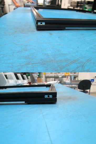
Back Frame:
For the back frame we will follow the same steps we did for the front frame with one exception, we will add one extra t-nut to the single tap extrusion bar on the left side of the frame.

To start we will take our back frame and place it with the tapped holes facing you, and the corners laying on the table.
Place one t-nut in the outward facing channel on the left and right extrusions.
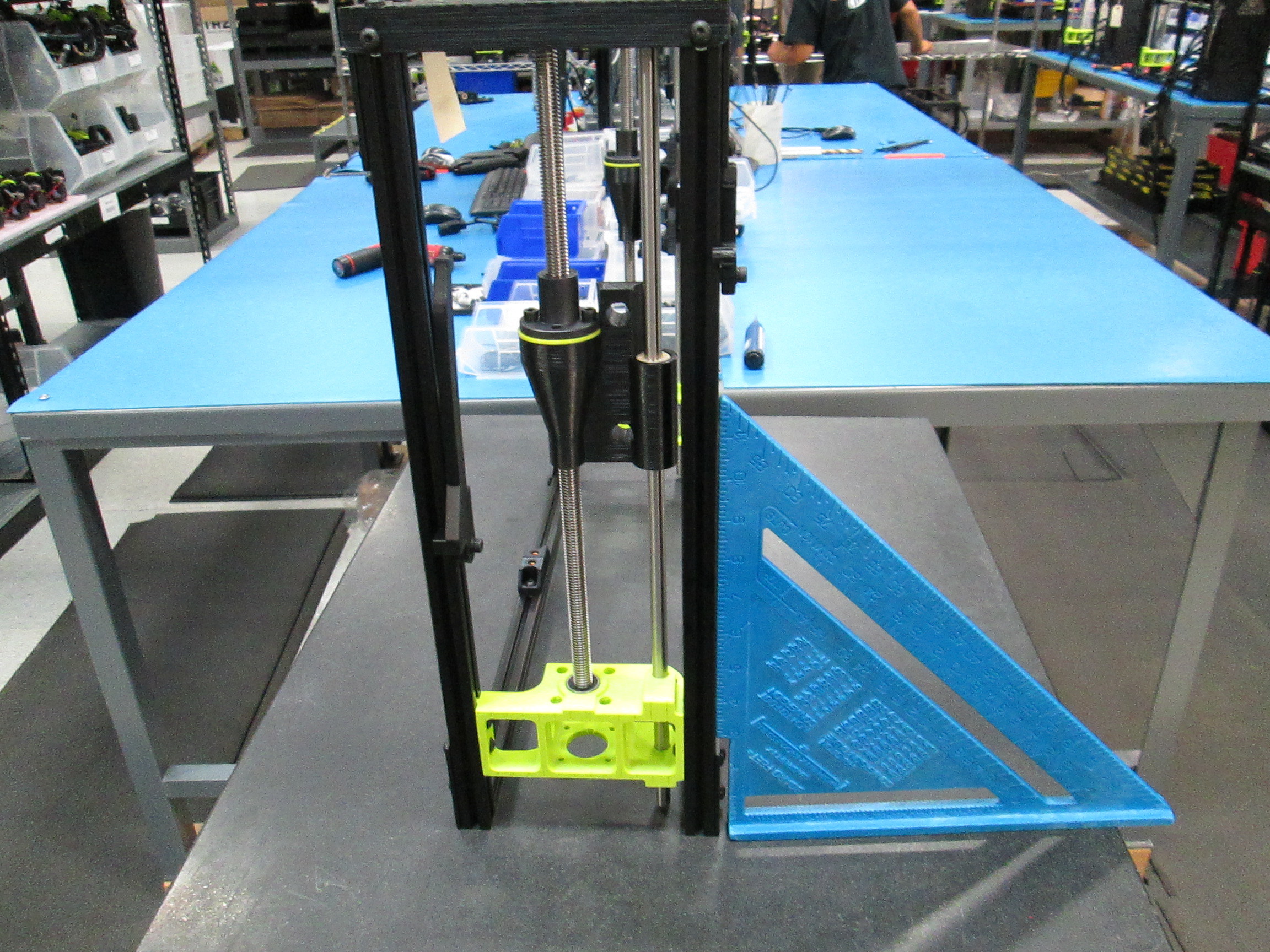
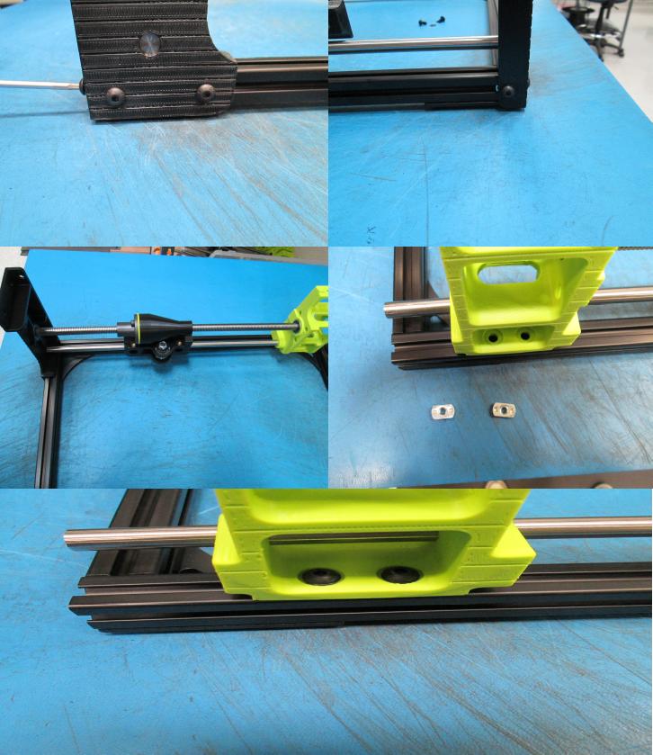
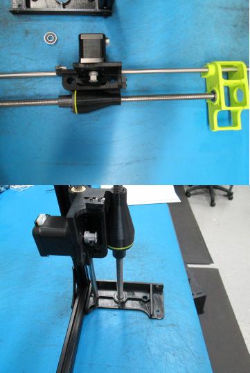
Now that we have the t-nuts in place we will install the z-axis right (AS-PR0017).
Start by taking one 608 bearing (HD-MS0282) and a z-upper (PP-GP0236), place the bearing in the z-upper then insert the right z-axis into the bearing and printed part.
Place the right z-axis onto the frame and secure the z-upper the the frame.
First screw the z-upper through the tapped hole in the extrusion using M5x10 BHCS (HD-BT0073) and M5 washers (HD-WA0040), then slide one of the t-nuts on the extrusion bar closest to you over to the z-upper and screw it down with an M5x10 BHCS and M5 washer, do the same for the t-nut on the side.
To secure the bottom of the right z-axis to the frame we will slide two t-nuts into the bottom of the extruson and screw two M5x10 BHCS with M5 washers.
Make sure that the drive rod on the right z-axis is fully seated into the bearing before tightening the screws.

Next we will attach the left z-axis onto the frame.
Take a 608 bearing and insert it into a z-upper.
Attach the z-upper to the frame using an M5x10 BHCS and M5 washer and screw into the tapped hole on the extrusion.
Slide over the other t-nut and finish screwing the z-upper to the frame.
Take frame and lay it so the z-uppers are laying on the table then take the left z-axis and insert it into the printed part.
Now we will take the frame and place it so that the frame is partially hanging off the table.
This will allow the motor to hang so we can properly secure the left z-axis to the frame.
Slide two t-nuts into the extrusion and screw them with M5x10 BHCS and M5 washers.

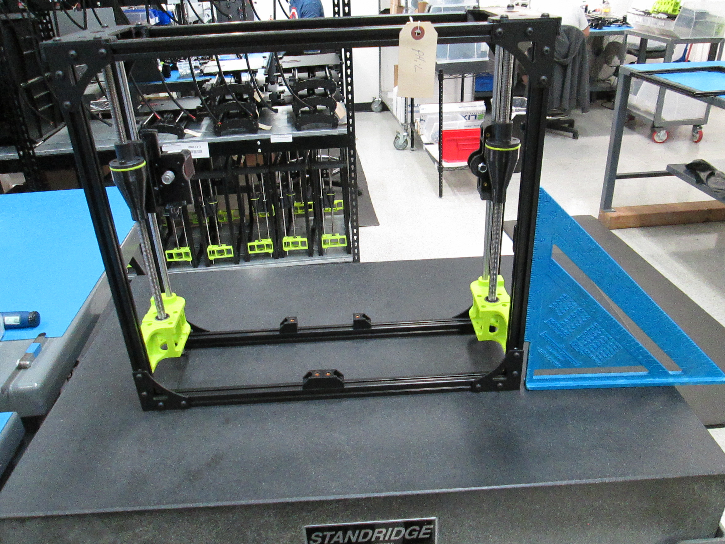
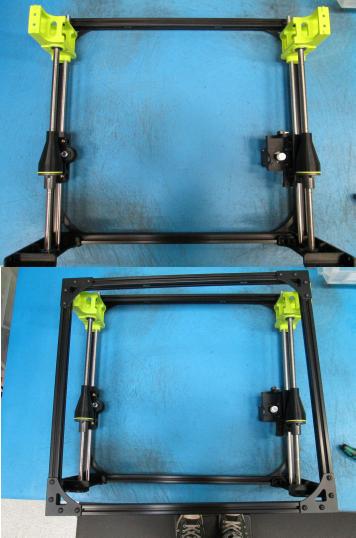
Now that we have our two z-axes secured to the back frame, we will take the front frame and place on the axes with the tapped extrusions facing toward you.
Slide one t-nut into the outer sides of the front frame like how we did with the back frame.
Secure the z-uppers to the front frame first using M5x10 BHCS and M5 washers and screwing into the taps first then sliding the two t-nuts on the top extrusion over and screwing them in.
Next screw the t-nuts on either side of the front frame to the z-uppers.
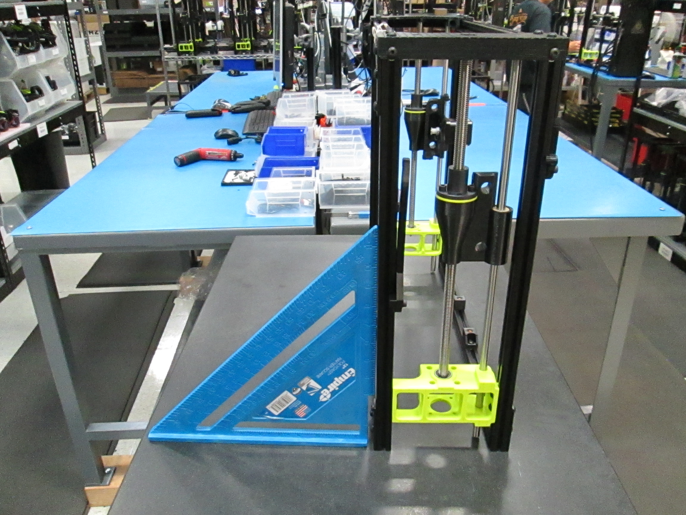
Now we will rotate the frame 180 degrees so the front frame is lying on the table.
We will secure the bottom of the z-axes to the front frame.
For the right z-axis slide two t-nuts in the extrusion and tighten it down using M5x10 BHCS and M5 washers.
For the left z-axis first we will slide in a spring t-nut (HD-NT0044) followed by a "normal" t-nut (HD-NT0053), slide thes both past the screw holes on the green z-lower printed part.
Then slide two more t-nuts (HD-NT0053) and secure the bottom of the left z-axis to the frame using M5x10 BHCS and M5 washers.

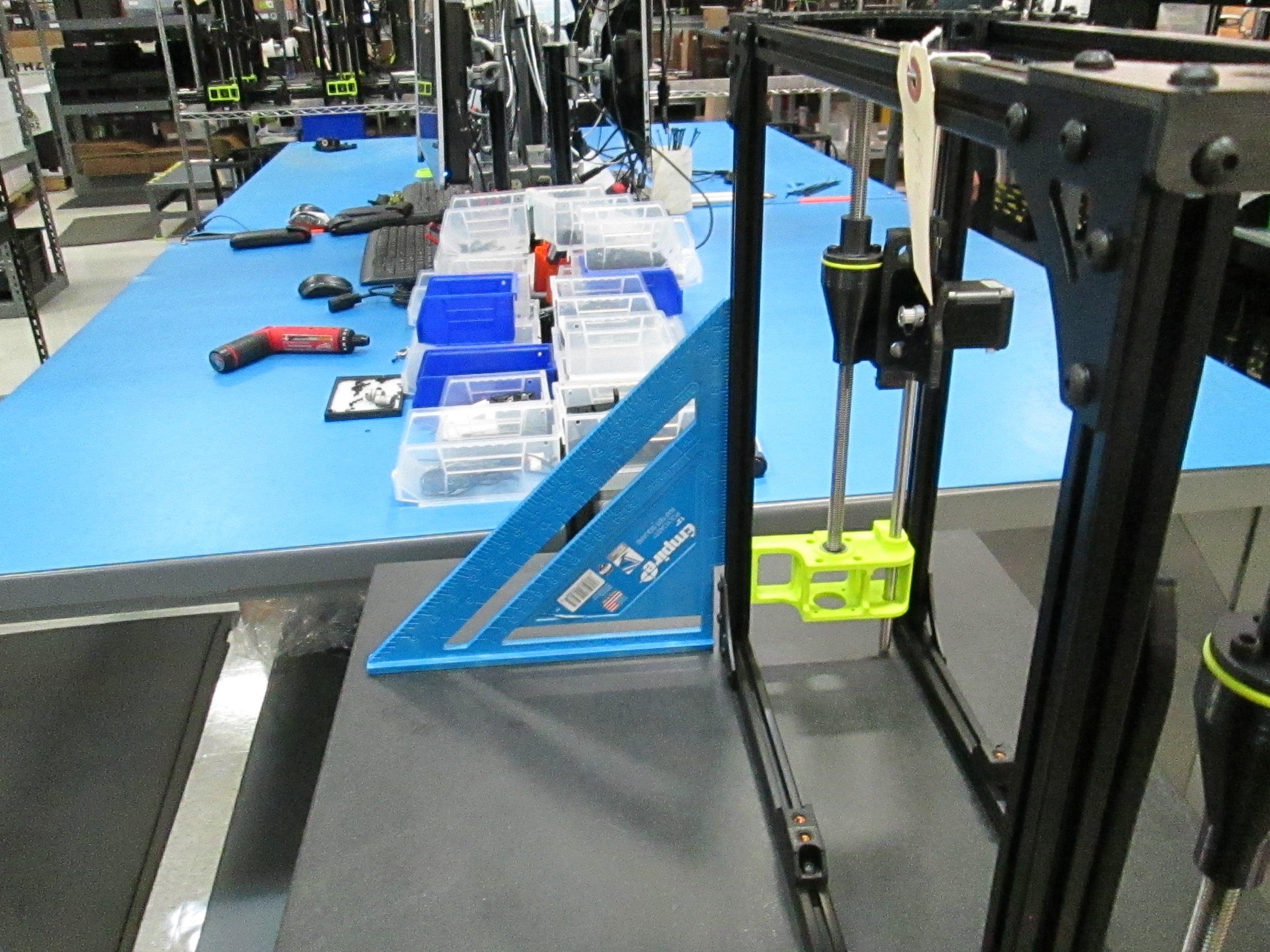
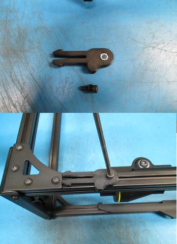
Almost done, we wll now attach the spool arm (AS-PR0012).
With the front frame still lying on the table, use one M5x14 SHCS (HD-BT0049) and M5 black washer (HD-WA0040) to screw the spool arm to the t-nut below the spring t-nut we installed on the previous step.
Use the spool arm jig to place the spool arm in the correct location on the frame.
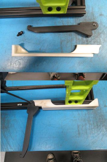
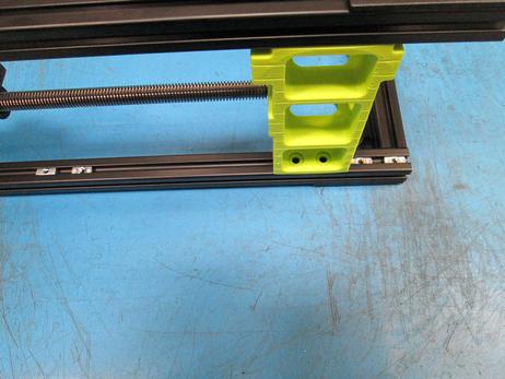
Now we will attach the tippy feed tube holder to the back frame, this will be on the same side as the spool arm.
On the back frame, left extrusion bar, there should be a t-nut we installed earlier.
Using one M5x14 SHCS and an M5 washer, start the screw and slide the feed tube holder up so when it is flipped up it is flush with the frame corner.
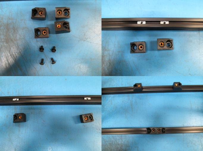
The last thing we will install before leveling and squaring the frame is the bed mount chassis (AS-PR0008).
Stand the frame up right with the front of the frame facing you, on the bottom extrusions there should be two t-nuts (HD-NT0053) in each bar.
Using M5x10 BHCS (HD-BT0073) and M5 black washers (HD-WA0040) tighten the bed mount chassis.
On the front extrusion place the bed mount chassis closly to each other, on the back extrusion place the bed mount chassis farther apart from each other.
This is to just help distinguish the front of the frame from the back.
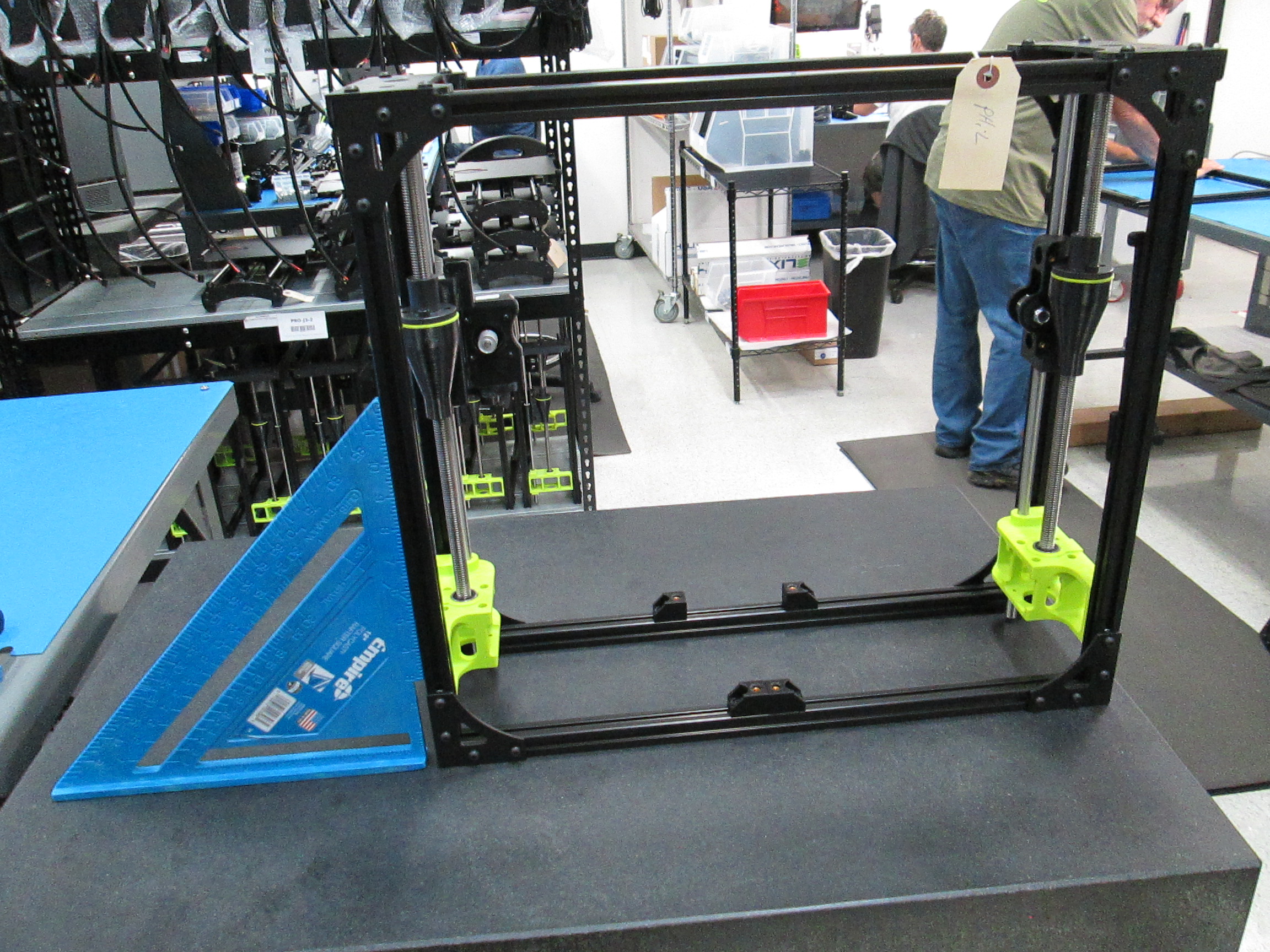
Now that we have fully assembled our frame we now have to make sure the frame is squared and leveled.
If the frame was properly assembled then there shouldn't be much to this step.
However if the frame is not quite square we will adjust the frame by placing it on a flat surface like our ISO 9001 certified granite block.
Place the frame on the granite block, if there is no wobble from the frame and when we put a square to the extrusions and we see no gaps greater than 2mm we can safely say the frame is square.
If when you place the frame on the block and the frame wobbles side to side then we need to adjust the frame until the frame no longer wobbles.
Ways to adjust the frame are to loosen the screws holding the green z-lowers and pushing the whole z-axis up and re-tightening them.
You can loosen the z-uppers and re-tighten them.
You can also loosen one side of the z-lowers to drop one side of the frame slightly.
Make sure the extrusion bars are flush with each other, make sure there are no gaps between extrusions or the bars aren't crooked.
In more extreme cases you can loosen the frame corners to let everything re-settle.
Just be sure to flush up the corners when you re-tighten them.
Once frame is square put the frame in its assembly location on the assembly floor ready for final assembly.