Open HardwareAssembly Instructions
Guides for installation and assembly of the LulzBot line of products made by FAME 3D LLC.
Guides for installation and assembly of the LulzBot line of products made by FAME 3D LLC.
Required Items:
Completed TAZ unit (AS-PR0003 final mechanical assembly)
Appropriate power cable (EL-CA0030 for NA, EL-CA0031 for England, EL-CA0032 for EU, or EL-CA0056 for AU)
USB cable (EL-CA0063)
Customer deliverable programmed SD Card (EL-MS0385 with installed files)
Feed Tube (AS-PR0082)
TAZ 6 Acceptance Record (DC-MS0049)
TAZ 6 heat Bed (AS-PR0002)
Bed spacer x 4 (HD-MS0287)
Bed leveling washer x 4 (PP-MP0082)
Bed leveling screws x 4 (HD-BT0082)
Tools:
M4 Ball Hex driver
M3 Ball Hex driver
M2.5 Ball Hex driver
M2 Ball Hex driver
M1.5 Hex driver
M1.3 hex driver
Needle Nose Pliers
Flush cutters
Clam Knife
Check that all hardware is present and properly torqued.
Torque Values:
Spool Arm: 5 in*lbs
Tippy Feed Tube Holder: 8in*lbs
Frame: 40 in*lbs
Y End Plate: 8 in*lbs
Y corner Left/Right: 5 in*lbs
Y Mount Chassis: 8 in*lbs
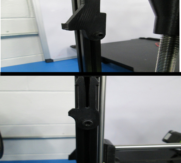
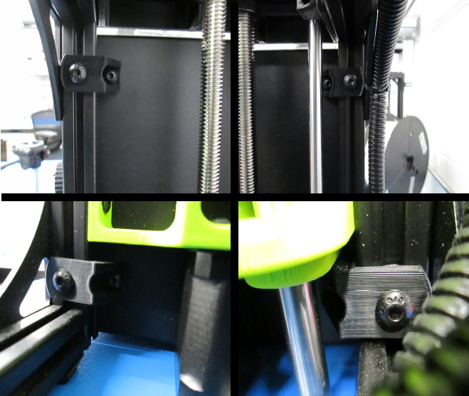
Z Lowers: 8 in*lbs
Z Uppers: 5 in*lbs
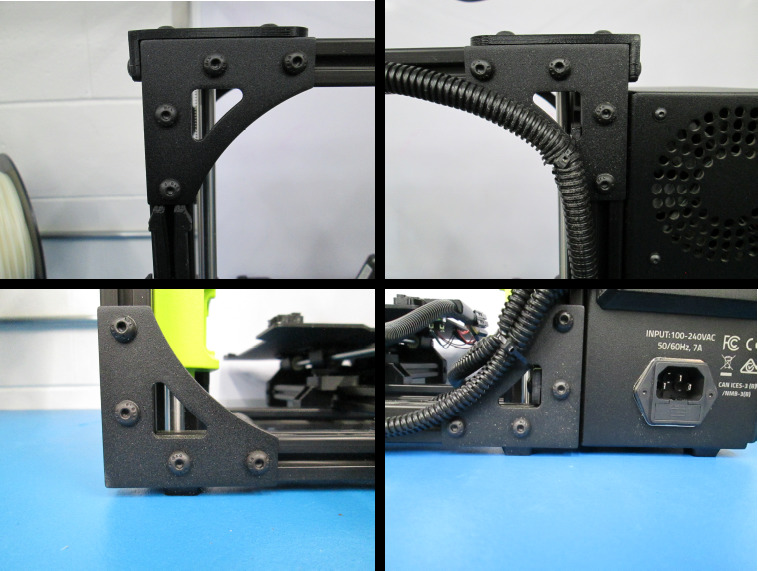
Frame to Control Box: 5 in*lbs
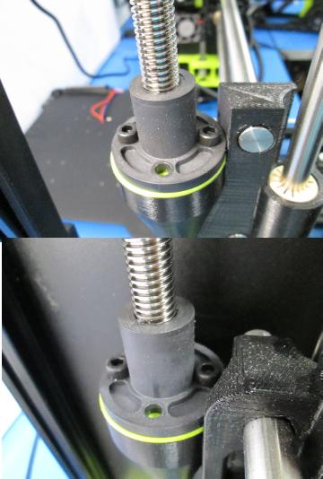
Z Nuts: Snug without binding
Toolhead: 5 in*lbs
X Belt Mount: 5 in*lbs
Case fan & Interconnect housing: 5 in*lbs
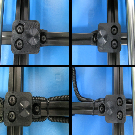
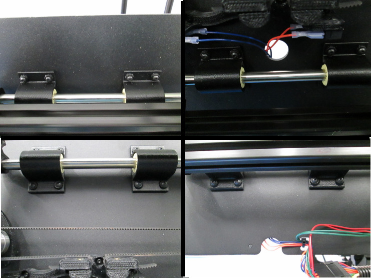
12mm Single Bearing Holder: 5 in*lbs
12mm Double Bearing Holder: 5 in*lbs
Bed Plate to Single Bearing: 5 in*lbs
Y Belt Mount: 5 in*lbs
Feet on Y corners: 3 in*lbs
Y Motor Mount: 5 in*lbs
Y Motor: 5 in*lbs
Y Idler Mount: 5 in*lbs
Electronics case cover: 5 in*lbs
Z Motors: 5 in*lbs
X Motor: 5 in*lbs
Smooth Rod Setscrew: 2 in*lbs
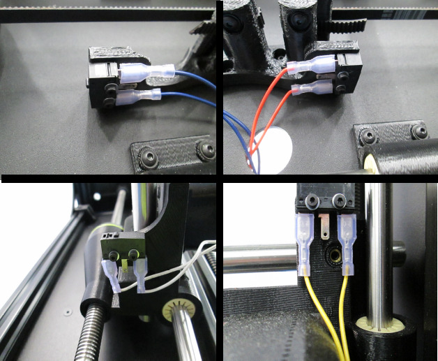
Limit Switches: 2.5 in*lbs
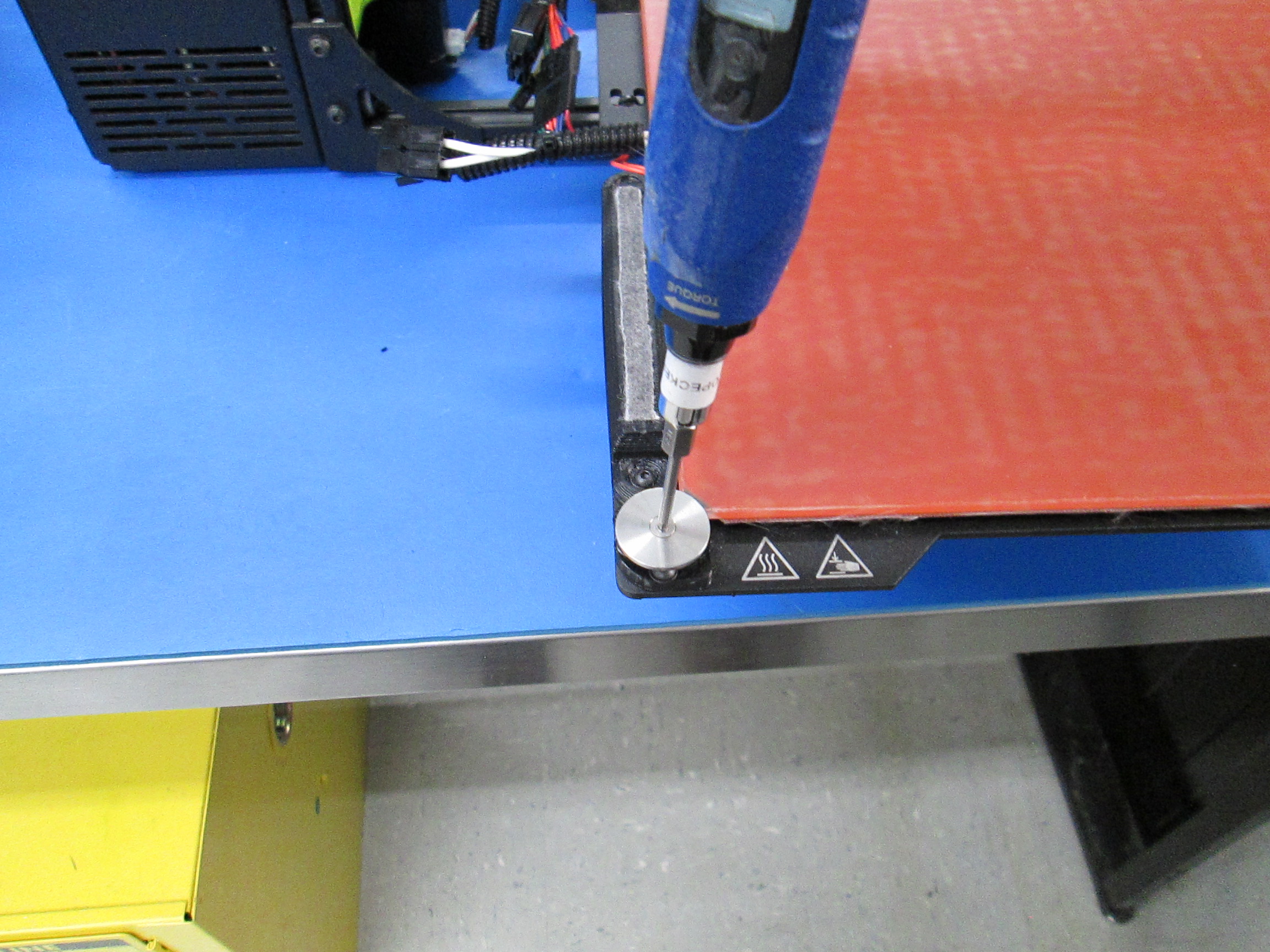
Bed Leveling Washers (once installed): 5 in*lbs
Wiper Mount: 5 in*lbs
Zmin Switch Mount: 5 in*lbs
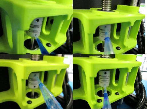
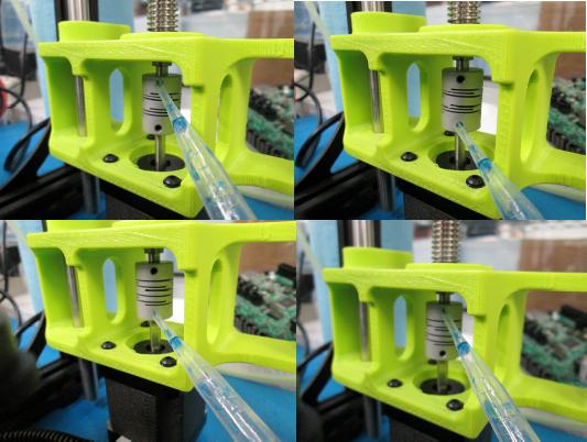
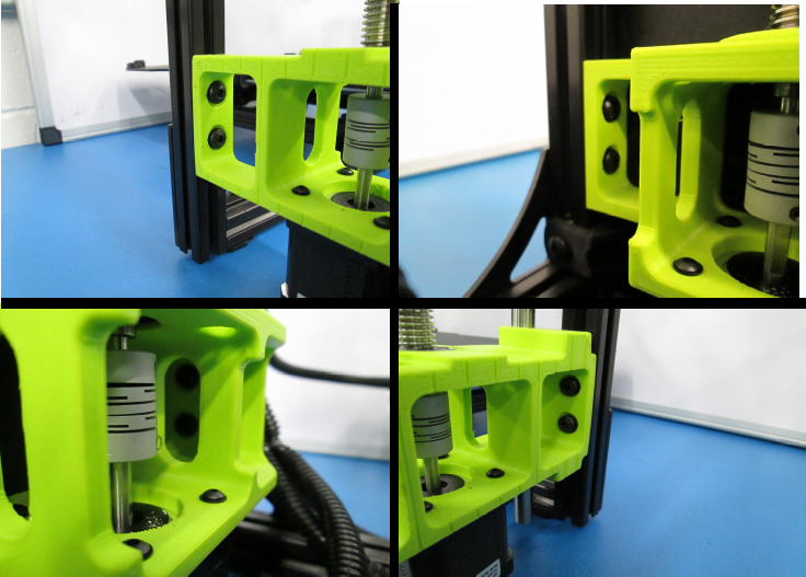
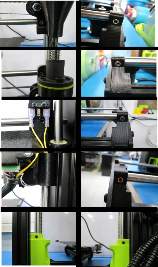
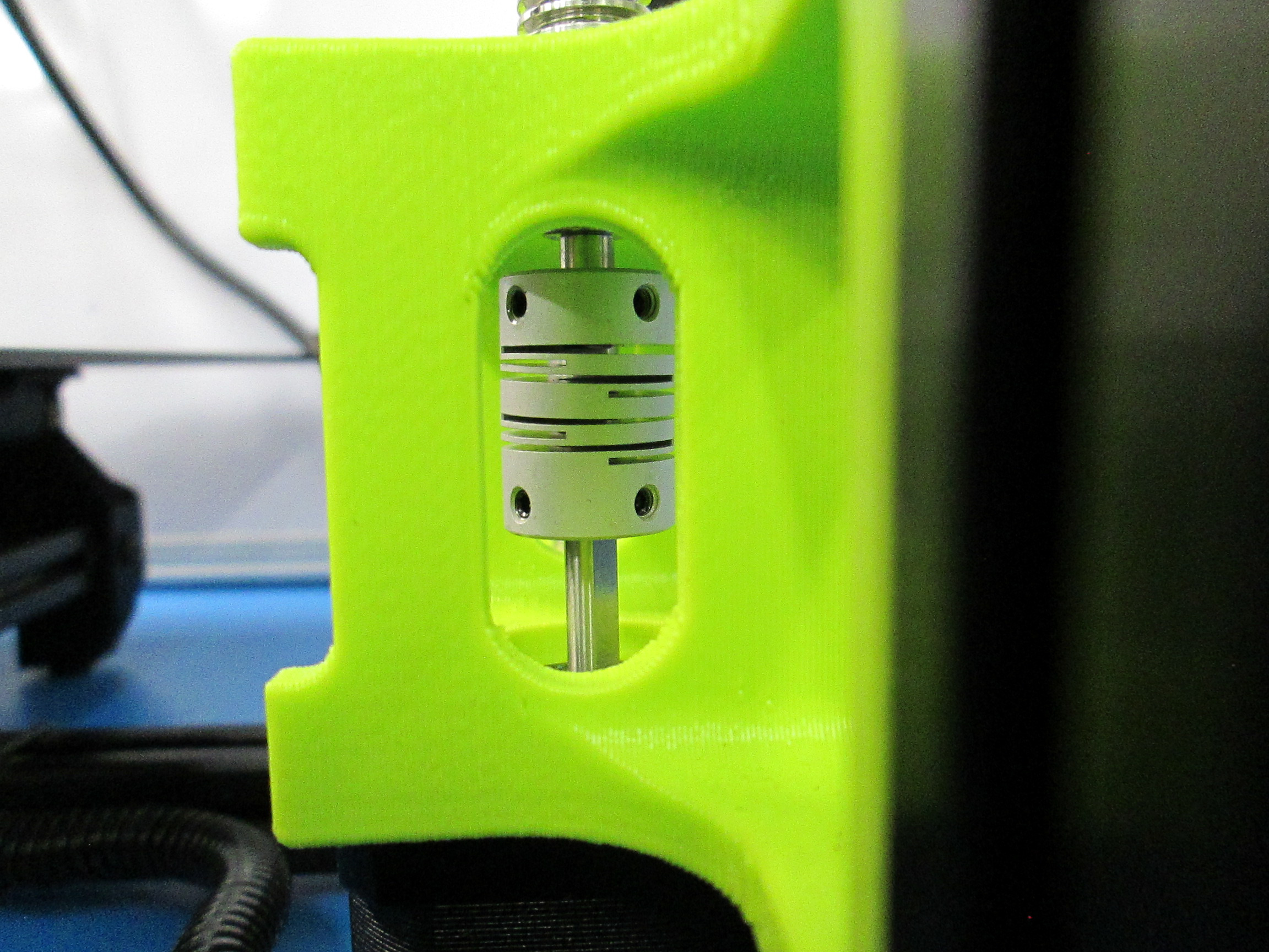
Couplers: 5 in*lbs
Pulleys: 2.5 in*lbs
Inspect all printed parts for damage or imperfections.
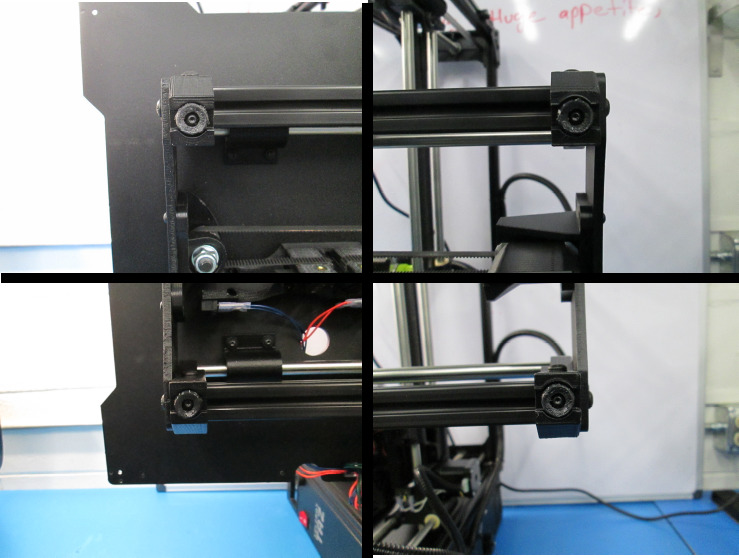
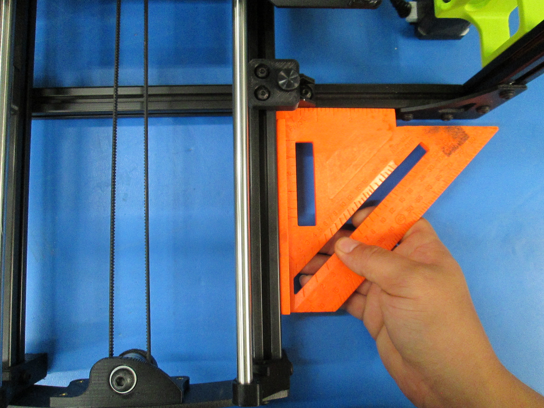
Check the square of the XY axes.
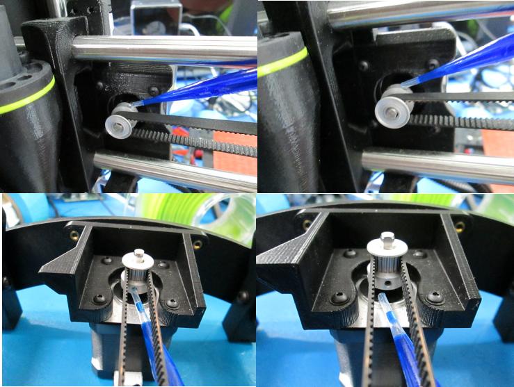
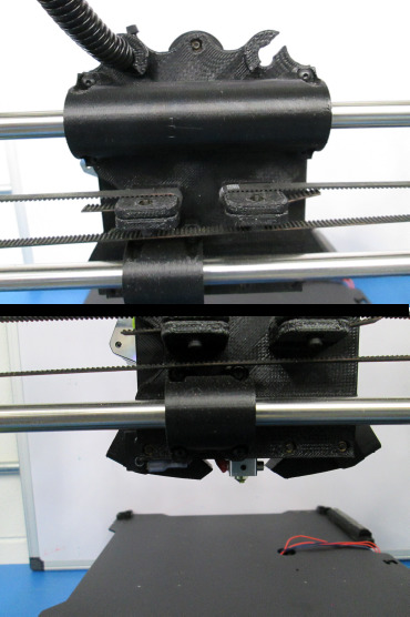
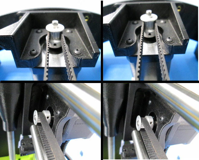
Check belt alignment.
Adjust belt tension using the Sonic Belt Tensioner. The belt tension should be between 23 and 27 Newtons.


Insert the pre-loaded SD card (EL-MS0385).
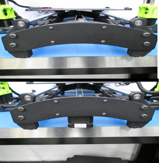
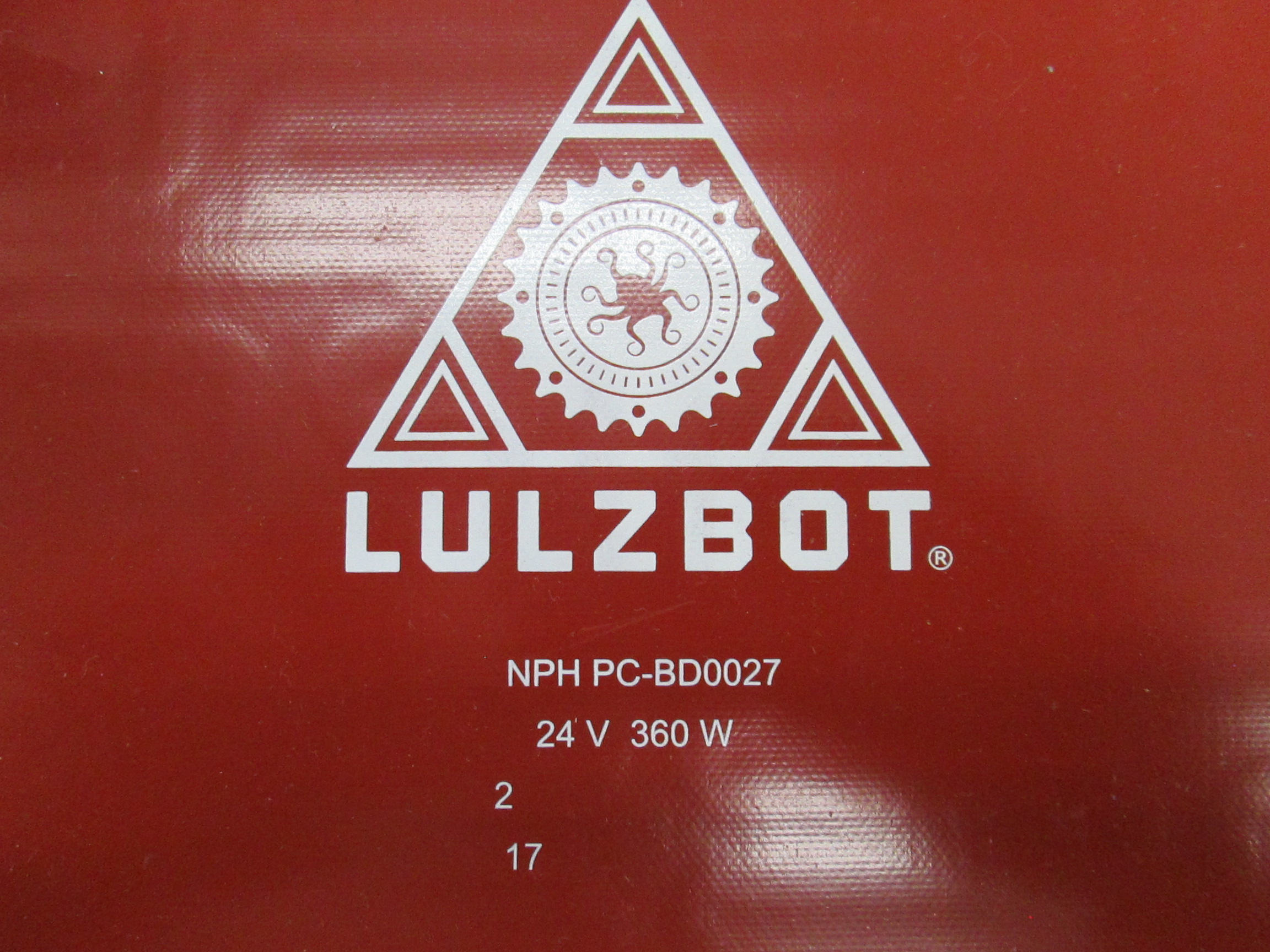
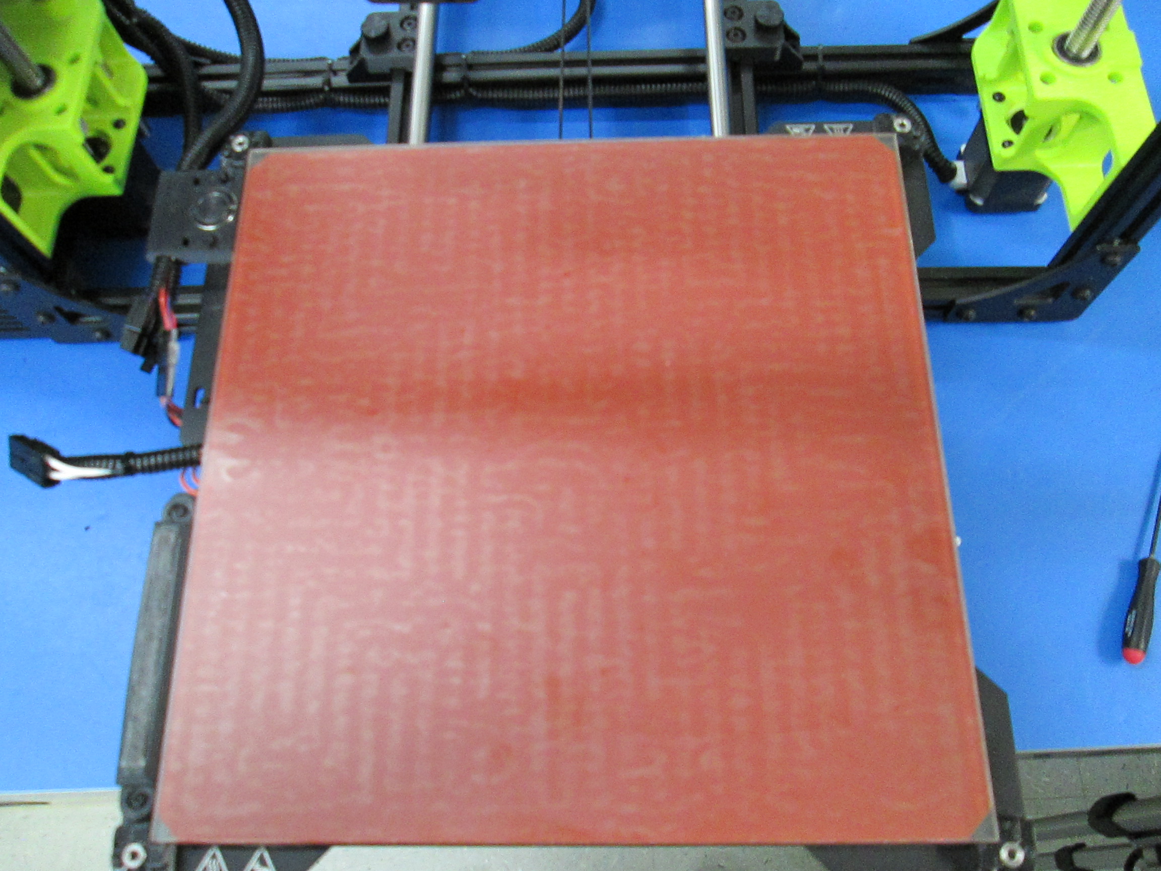
Record the batch number of the heat bed on the quality assurance record.
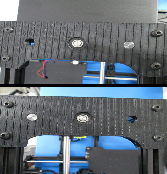
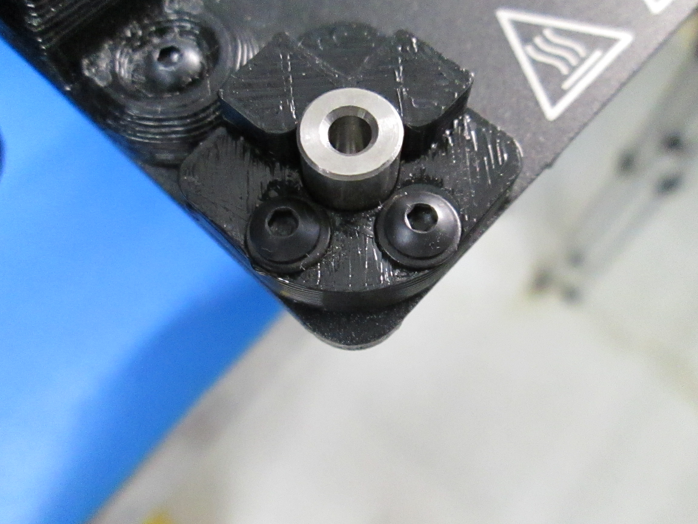
Install bed spacers (HD-MS0287) in the ninjaflex bed corners.
Tighten ninjaflex bed corner screws until the ninjaflex just starts to depress.
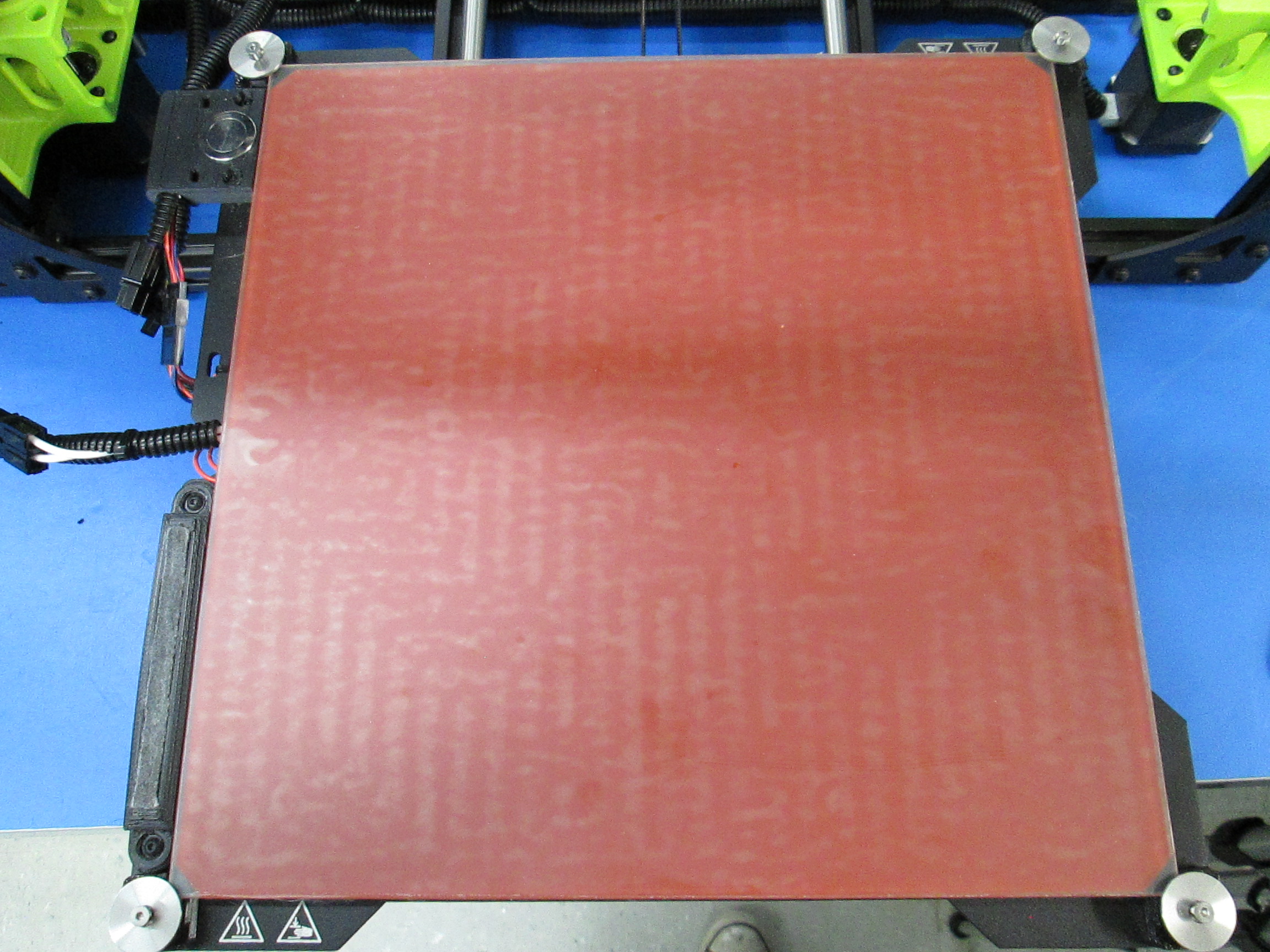
Install the heat bed (AS-PR0002) and torque the bed leveling screws (HD-BT0082) with bed leveling washers (PP-MP0082) to 5 in*lbs.
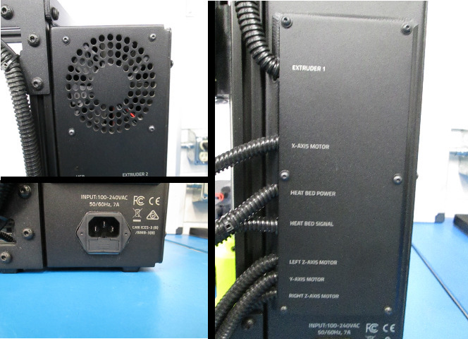
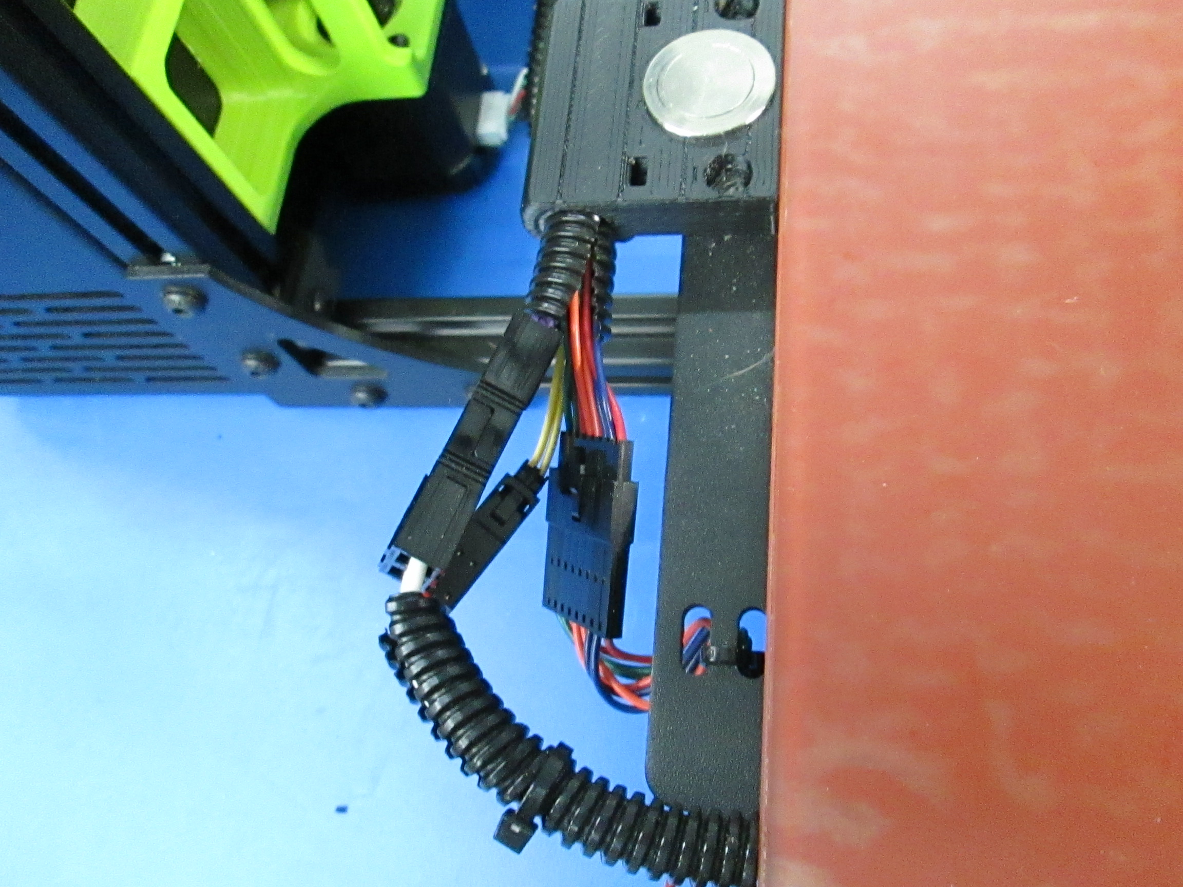
Make sure to plug in the heat bed heater wires and thermistor wires.
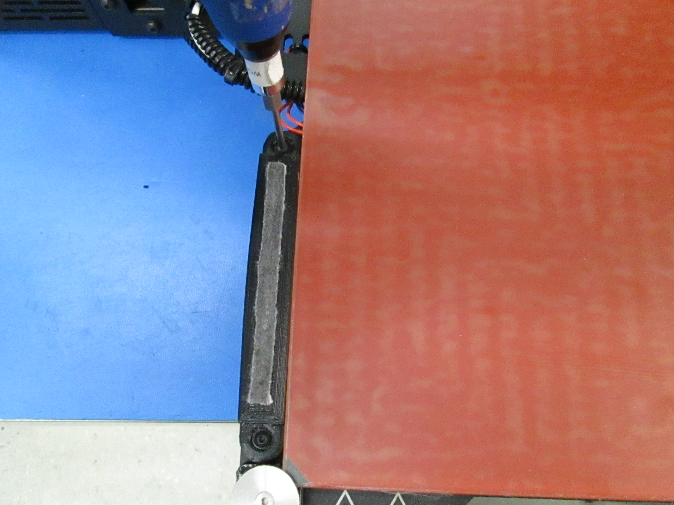
Ensure the wiper pad mount is properly tightened.
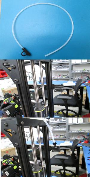
Install the feed tube assembly (AS-PR0082).
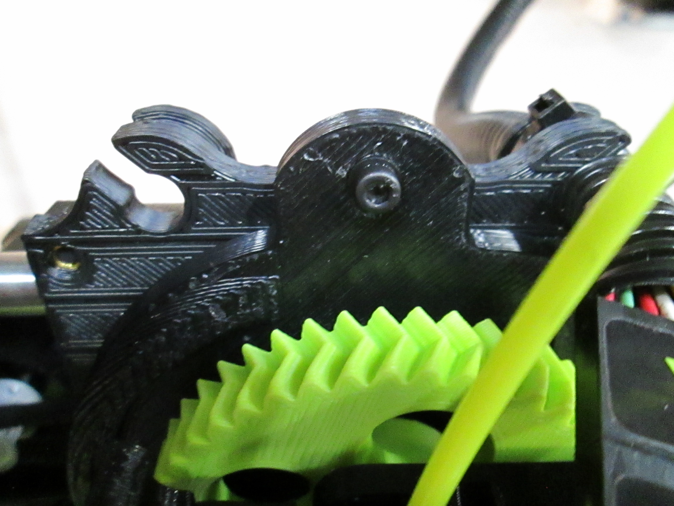
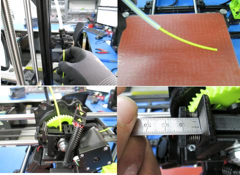
Using 3mm Lulzbot Green Ngen filament, feed the filament through the feed tube and into the hot end.
Adjust the extruder latch tension using the spacer jig or ruler.
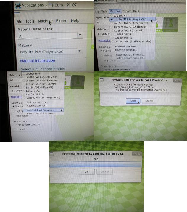
Connect the printer to CURA and install the latest version of the firmware.
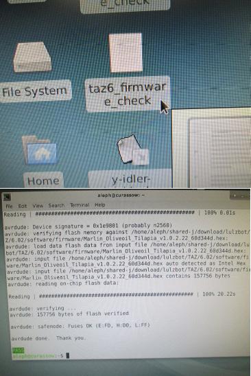
Run the firmware check to ensure the firmware was properly uploaded.
While connected to Cura check that the case fan and the heatsink fan run.
Ensure the functionality of the cooling fans. In the Cura terminal use the command M106 S1 and check that both cooling fans run. Repeat with M106 S102, and M106 S255. To turn off the fans use M107.
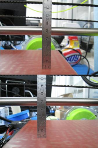
Home the printer and check that the x gantry is level.
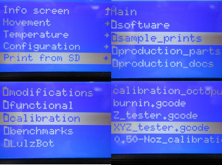
Now load and run the XYZ tester gcode. Make sure the Z axis isn't squeeky and that the machine doesn't exhibit any z-binding. Check that the belts are properly aligned as the machine runs through the axes of motion.


Heat up the printer to 230 degrees Celsius.
Purge filament to make sure the filament is coming out of the nozzle when you start the Extruder e-Step test.
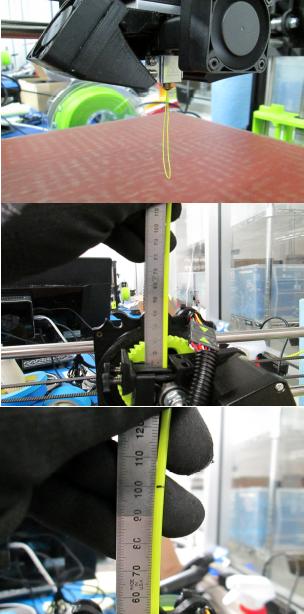
Make a mark 100mm from the top of the extruder body on the filament.
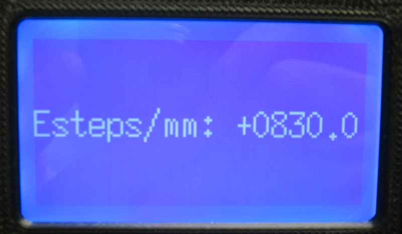
First check to see if the default e-Steps are correct. (Default e-Steps are 830)
If default e-steps are incorrect than you need to change the e-steps so that 100mm of filament is being extruded. To find the new e-Steps use this equation: e-steps divided by amount extruded multipled by 100. For instance if your e-steps are at 830 and you extruded 98mm of filament you would do (830 ÷ 98) x 100 = 846. This is your new e-step value. This works the same if you over extrude filament just do (830 ÷ 102) x 100=813.7 but we can round our number to 814.
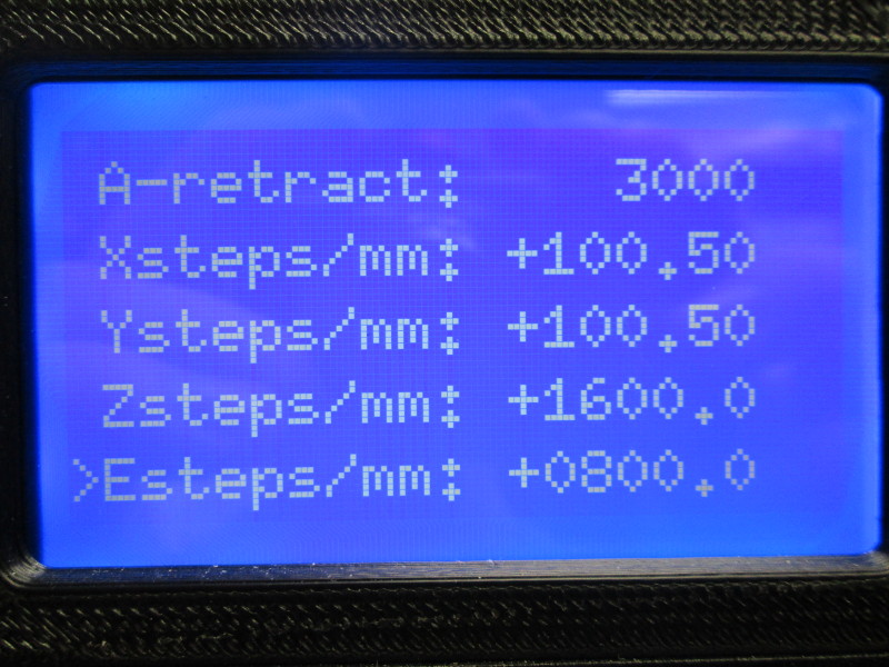
Place the e-Step value temporarily recorded on the extruder into the unit under test (UUT) eeprom via the LCD
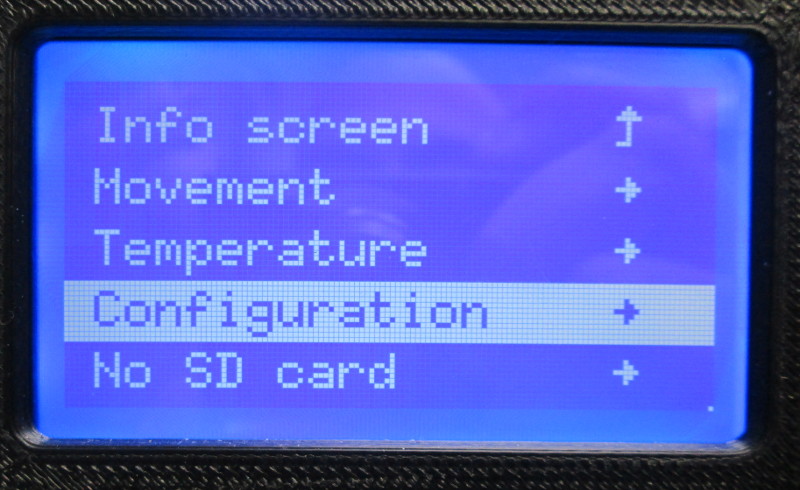
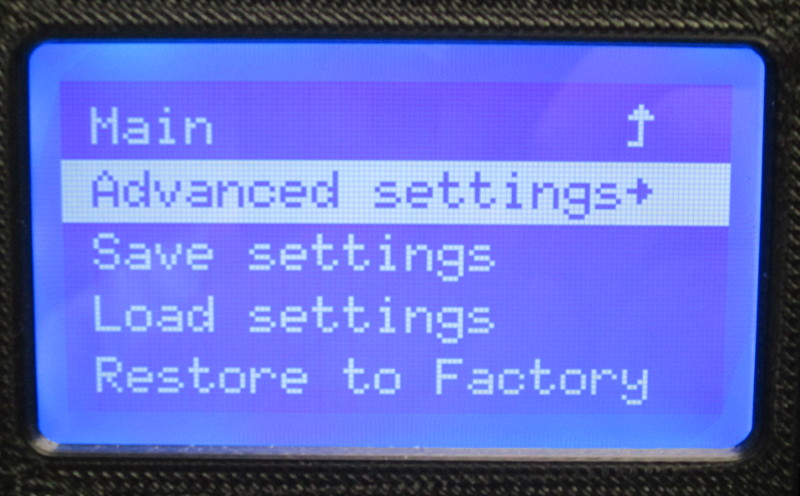
Using the LCD Menu navigate to: - - Configuration --> Advanced Settings --> Esteps/mm
Verify that it's saved in eprom by navigating back to the Esteps/mm menu displays the new value
Using the SD card that will be shipping with the unit to the customer run the calibration gcode loaded on the SD card
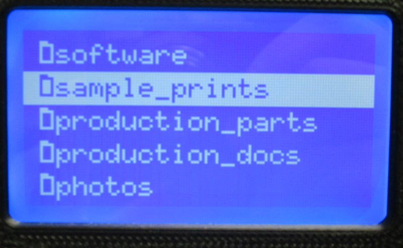
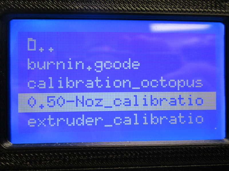
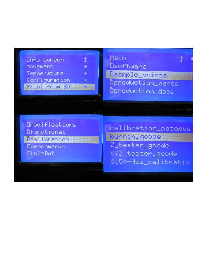
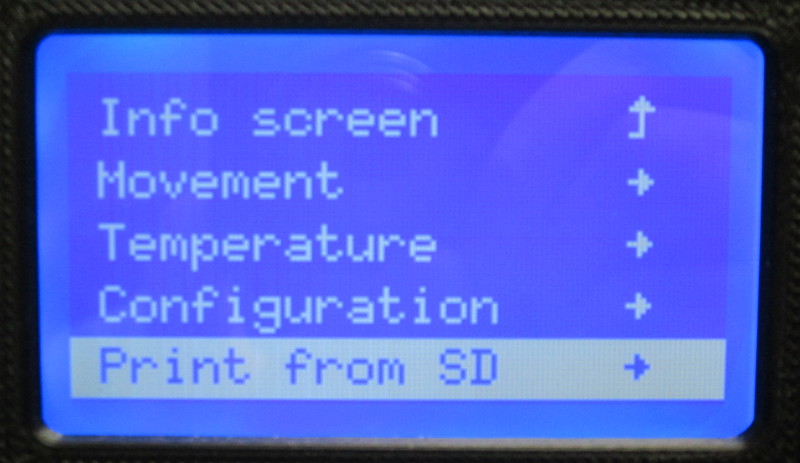
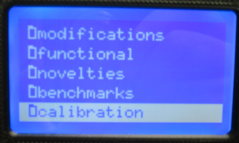
Using the LCD Menu navigate to: - - Print from SD --> Sample_Prints --> Calibration --> 0.50-Noz_calibration-100mm-90.gcode


Carefully go through the checklist on the test/acceptance record filling out as much as possible up to this point.
We will now run the Burn In Gcode.
Using the SD cart that will ship to the customer with the UUT, select the gCode saved on the SD card that will ship with the printer
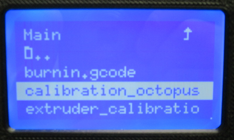
print from SD --> Calibration --> burnin.gcode
Using the SD card that will ship to the customer with the UUT, select the gCode saved on the SD card via the LCD screen
print from SD --> Calibration --> calibration_octopus_taz6.gcode
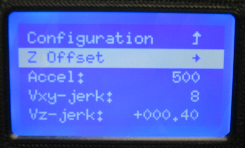
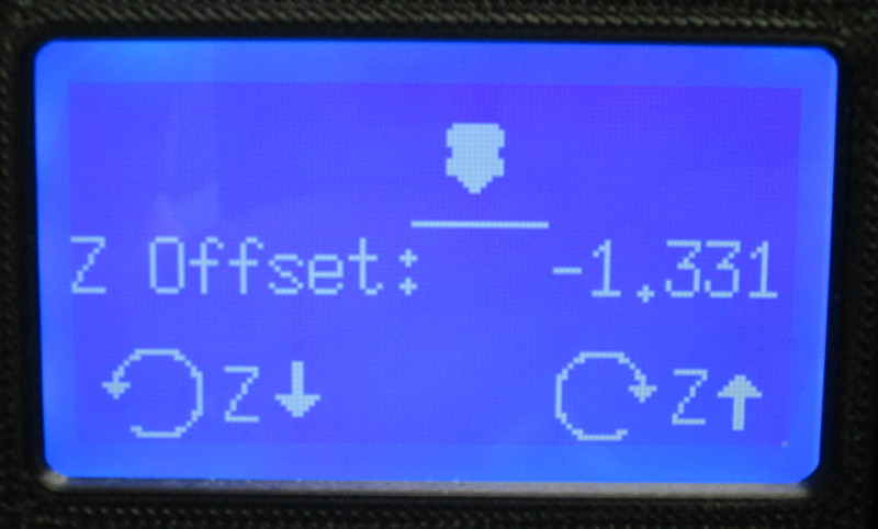
This octopus gcode has a spaced out skirt, set the z-offset through the LCD during the skirt
Configuration--> Advanced Settings --> Z-Offset
You MUST click the center knob at the desired Z offset
Now save the Z offset to EEPROM
Configuration--> Save Settings
When the print is done, check that the offset has been changed after power cycling the printer.


When your octopus has finished printing there are several common things you want to look for in the print.
Flat lines: You will notice that the legs of the octopus where the leg curves, there will be a straight line either in the x-axis or the y-axis. Things to fix this can be tightening the belt, double checking both the set screws on the pulley are tight with one set screw on the flat, make sure the bed moves smoothly, if the bed doesn't move smooth than the motor may not pull the bed easily.
Z-wobble/banding: If you see waves in the body of the print that appear to be in equal increments this is an indication of z-wobble; if the waves are in inconsistent increments than it is more an indication of z-banding. The most consistent fix for this is to replace one or both drive rods. Start by replacing the drive rod on the side that looks worse.
Debris: If there appears to be debris in your print you can try and purge the hot end again by extruding filament until you no longer see debris coming out of the hot end. You can also do a "cold pull" which is heating the filament up to roughly 200-220° C so it expands and grabs debris, and letting it cool down to roughly 120-150° C and pulling out the filament and hopefully any debris left in the hot end.
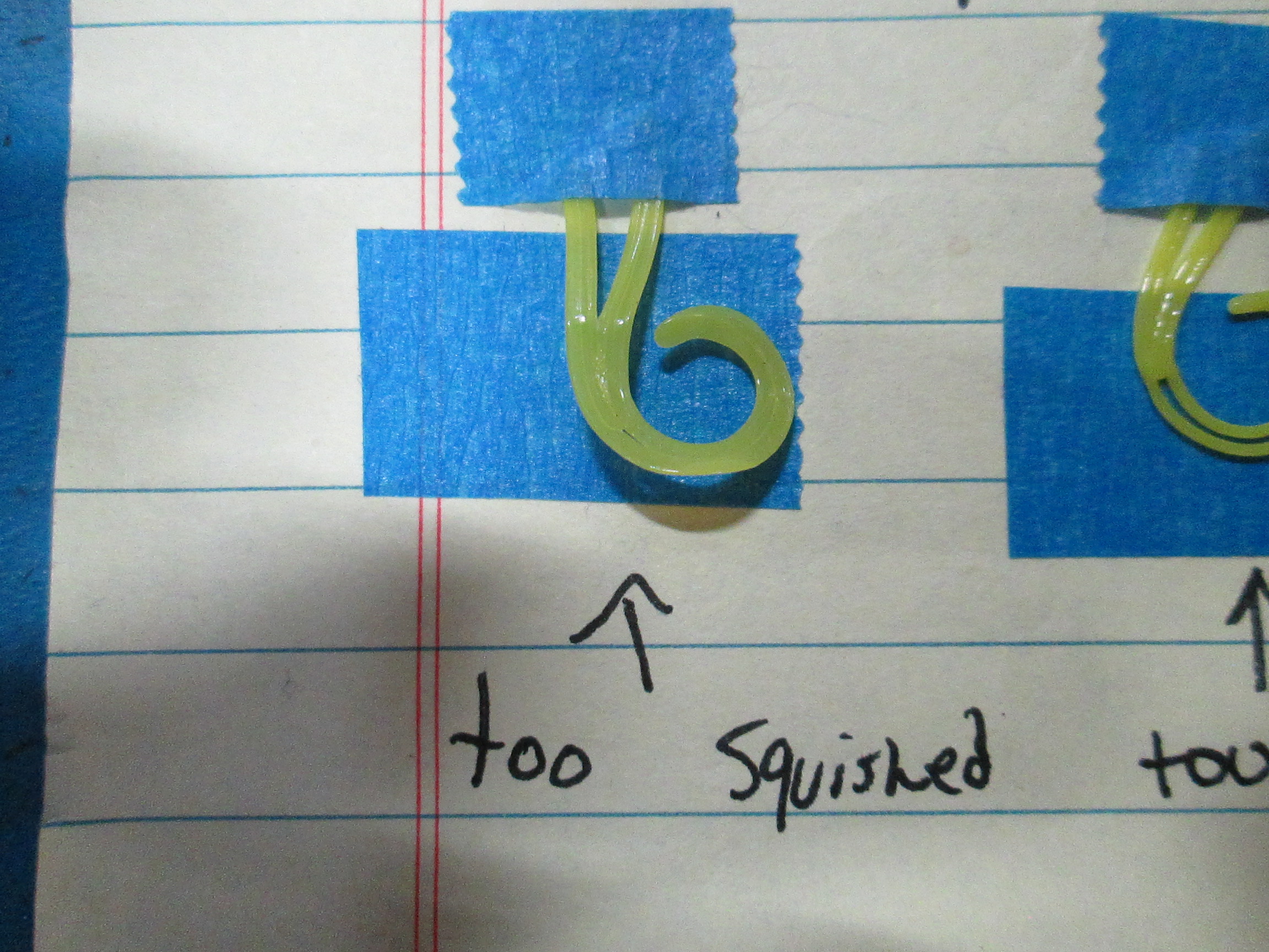
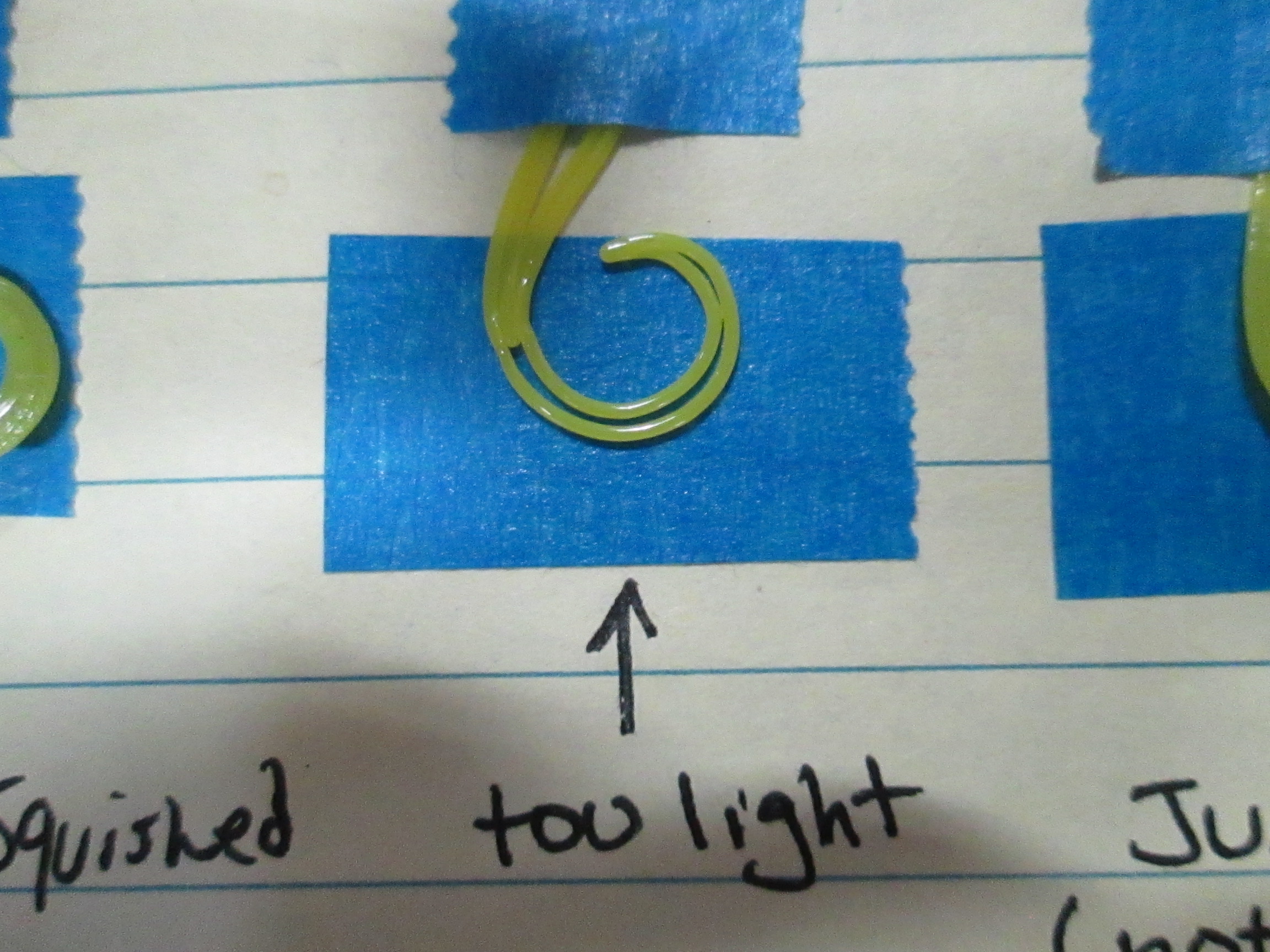
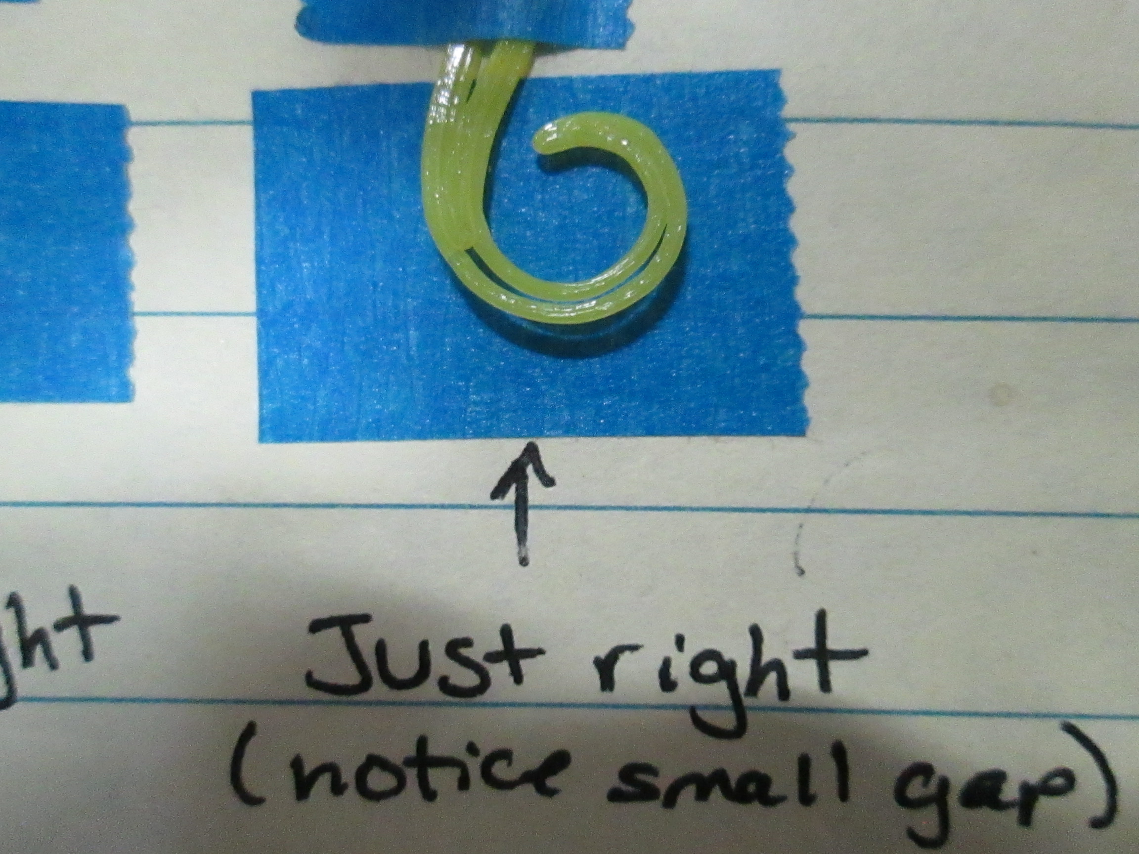
Squish: The bottom layer of the Octopus should not be under or over squished. You can measure the squish of the octopus by using a micrometer to measure the skirt of the print. The "skirt" is the outline of the print around the actual printed object.
If it appears to be over or under squished, measure the skirt to confirm and repeat the octopus print and modify the z-offset.
The skirt should be between 0.325 and 0.450mm
Reprint until the skirt measures within this range and there are no other issues with the print.
Ensure that the eStep value and the z-offset are recorded correctly on the TAZ6 acceptance record and the printer master build log
Prepare the printer for packaging.
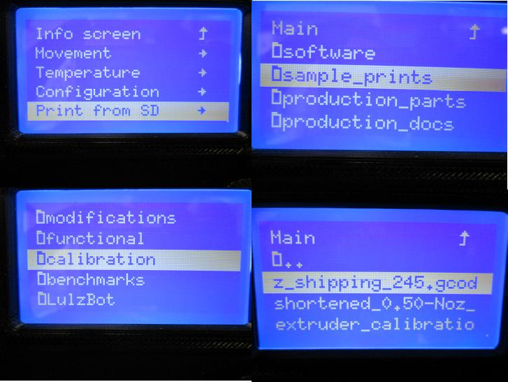
Using the SD cart that will ship to the customer with the UUT, select the z shipping gCode via the LCD
print from SD --> Calibration --> z_shipping_245.gcode
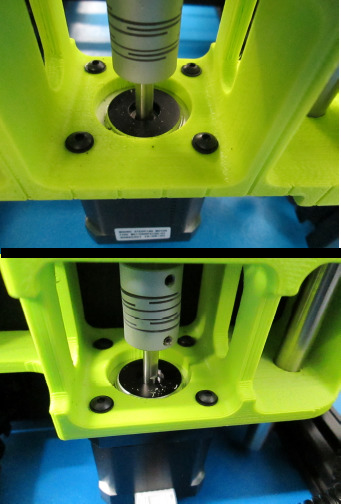
Before completing the Acceptance Record make sure to install loctite on the X and Y pulleys as well as the Z couplers.
Now complete the Test/Acceptance Record and log the machine in the Master Build Log.
Be sure you have the appropriate cables with the machine before sending the unit to packaging.