Open HardwareAssembly Instructions
Guides for installation and assembly of the LulzBot line of products made by FAME 3D LLC.
Guides for installation and assembly of the LulzBot line of products made by FAME 3D LLC.
Harness drawings located at:
Assembling Hexagon hot end:
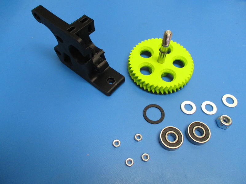
Gather parts
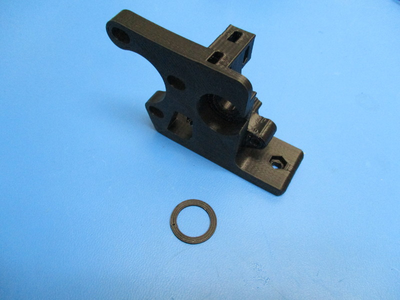
1x Extruder body (PP-GP0186)
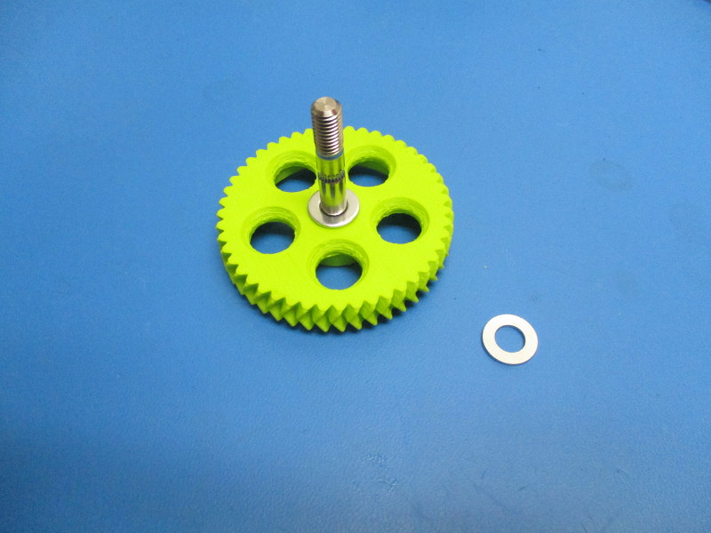
1x Large herringbone gear (AS-TH0003)
1x Extruder washer (PP-GP0060])
2x- 608 bearing (HD-MS0282)
3x- M8 washer (HD-WA0006)
1x M8 nyloc nut (HD-NT0002)
4x M4 nut (HD-NT0011)
Tools needed:
13mm wrench
Instructions
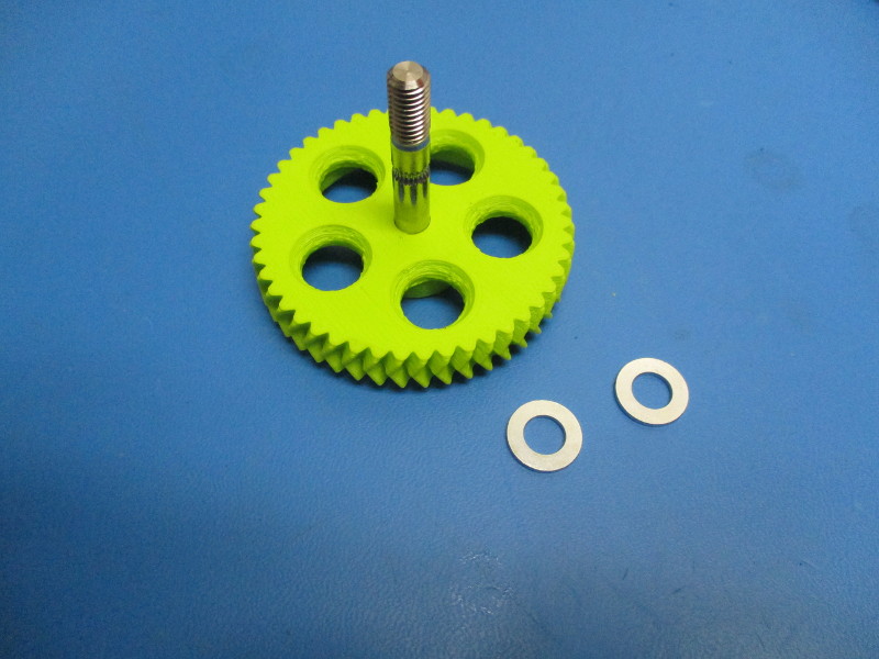
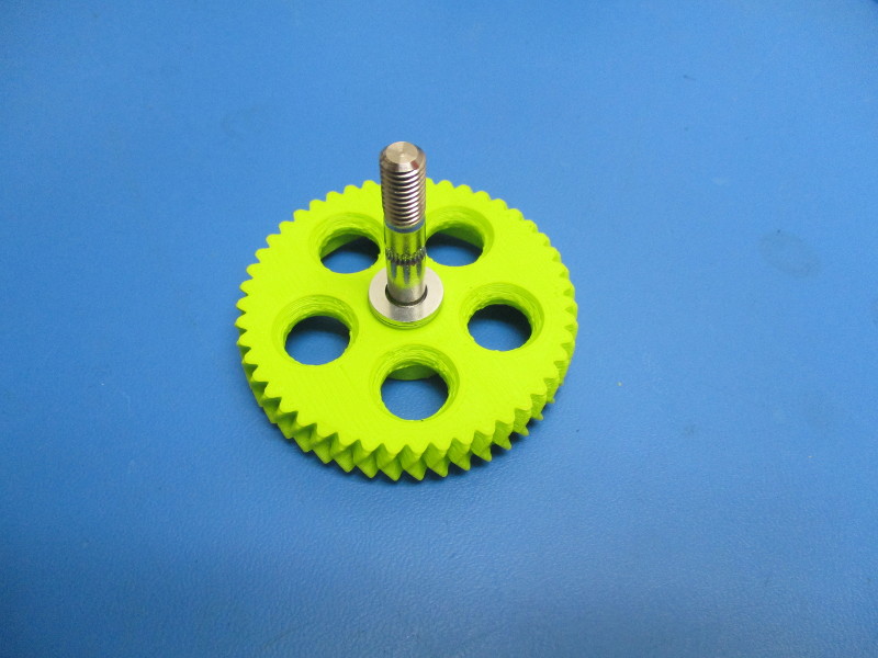
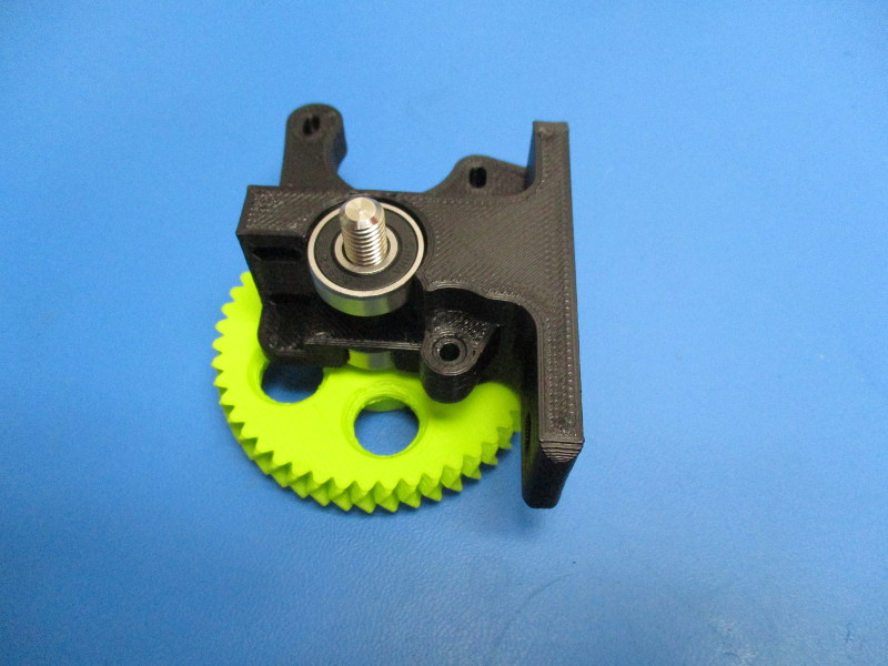
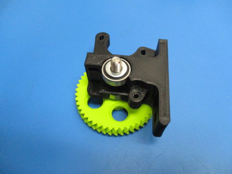
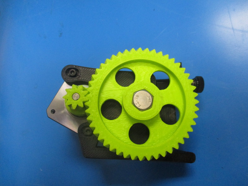
Install two M8 washers onto the bolt of the large herringbone gear.
Lay the extruder body so the flat face is facing upward. Install the extruder washer into the bearing pocket.
Press a 608 bearing into the bearing pocket.
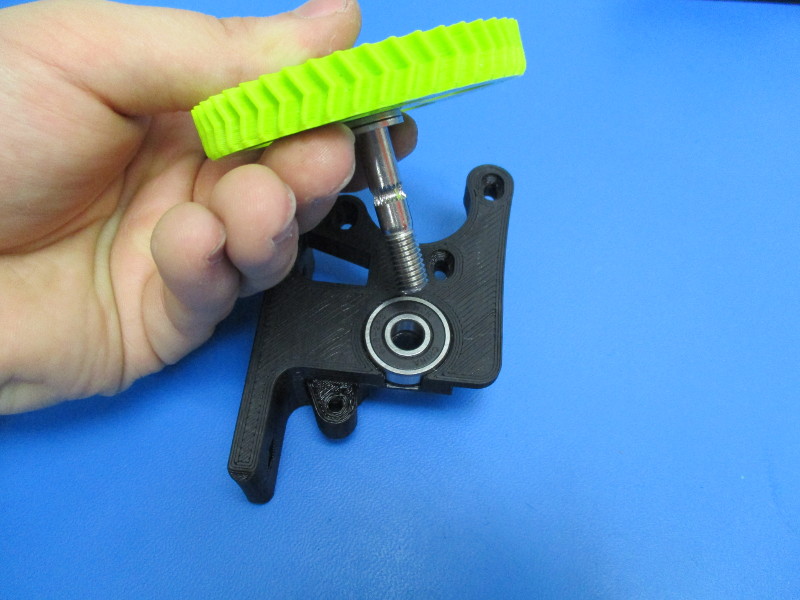
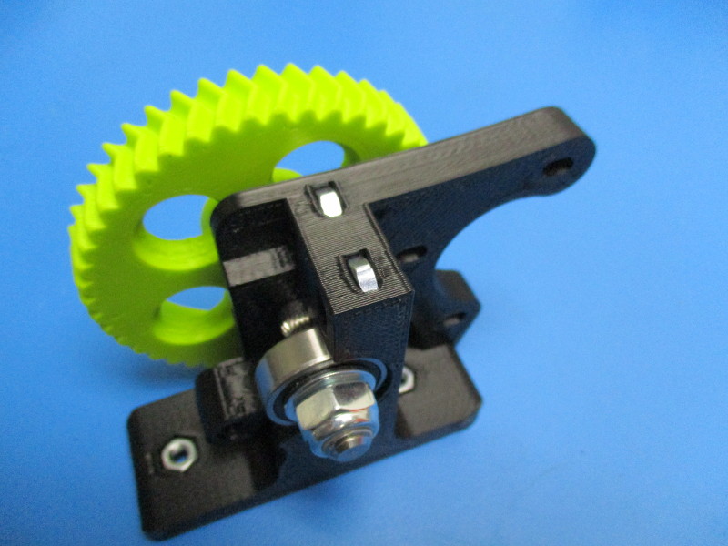
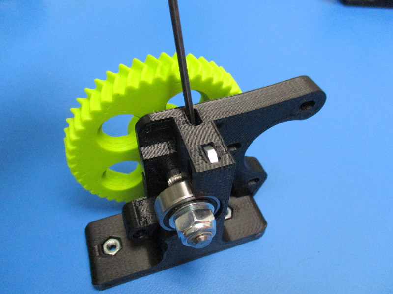
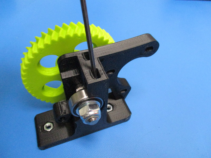
Install the large herringbone gear onto the extruder body by inserting the bolt into the bearing.
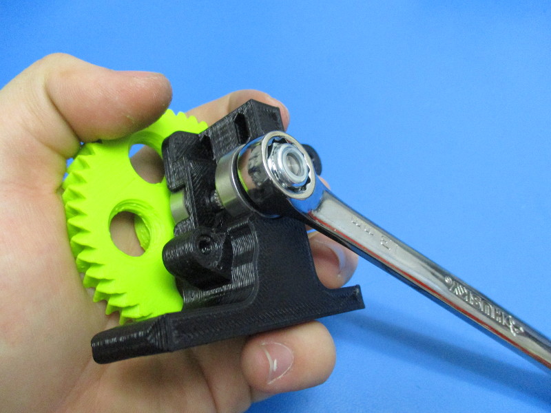
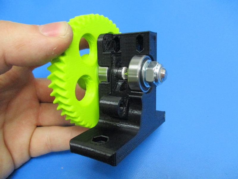
Flip the assembly over.
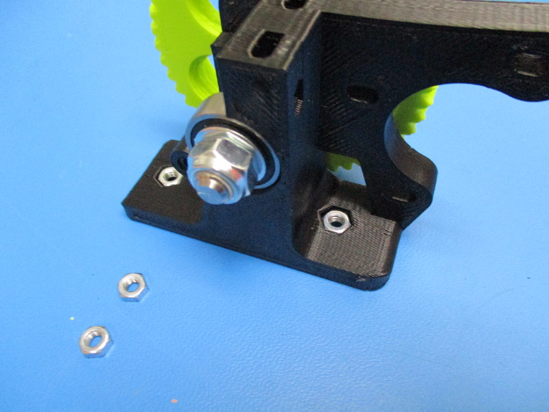
Install a 608 bearing onto the bolt coming out of the extruder body. Install a M8 washer fallowed by a M8 nyloc nut onto the bolt. Tighten the M8 nyloc nut until the washer doesn’t move freely
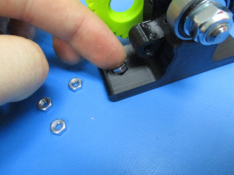
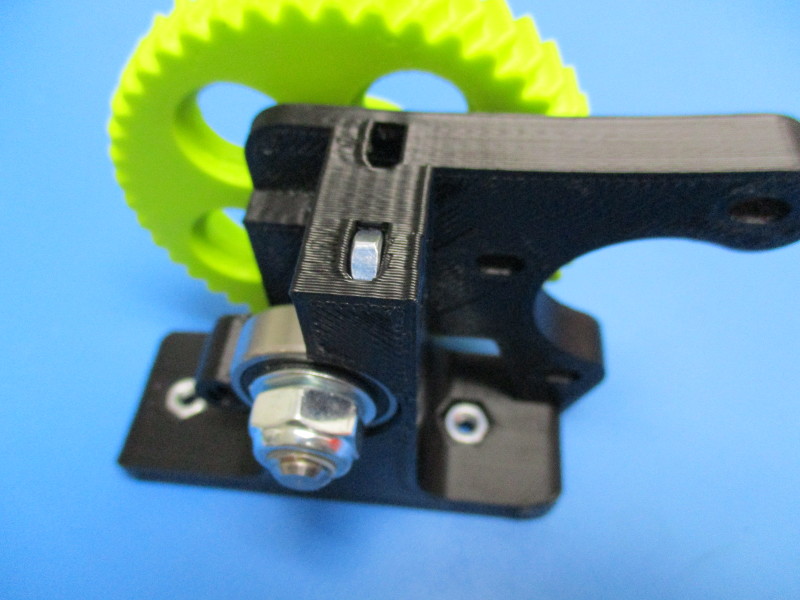
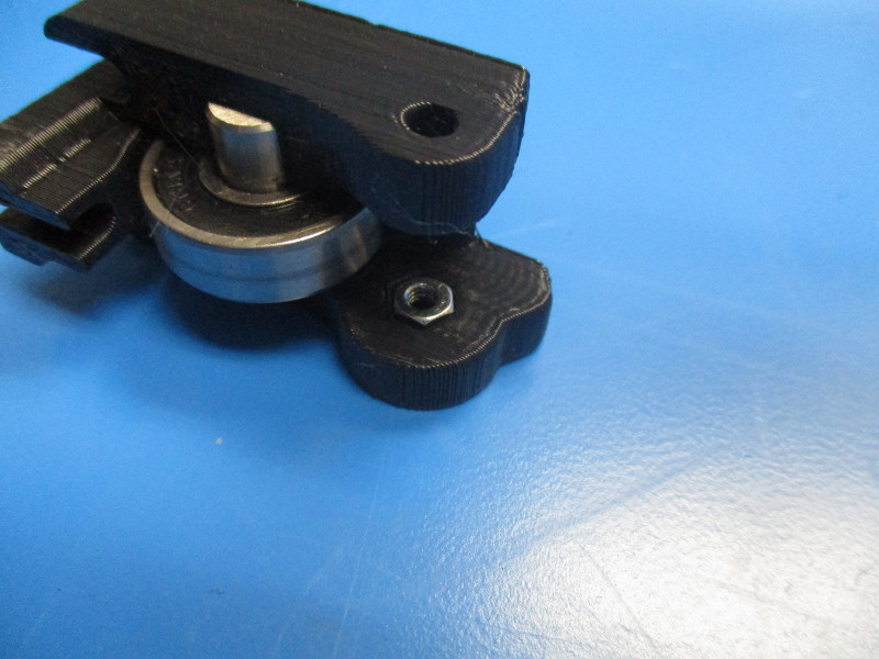
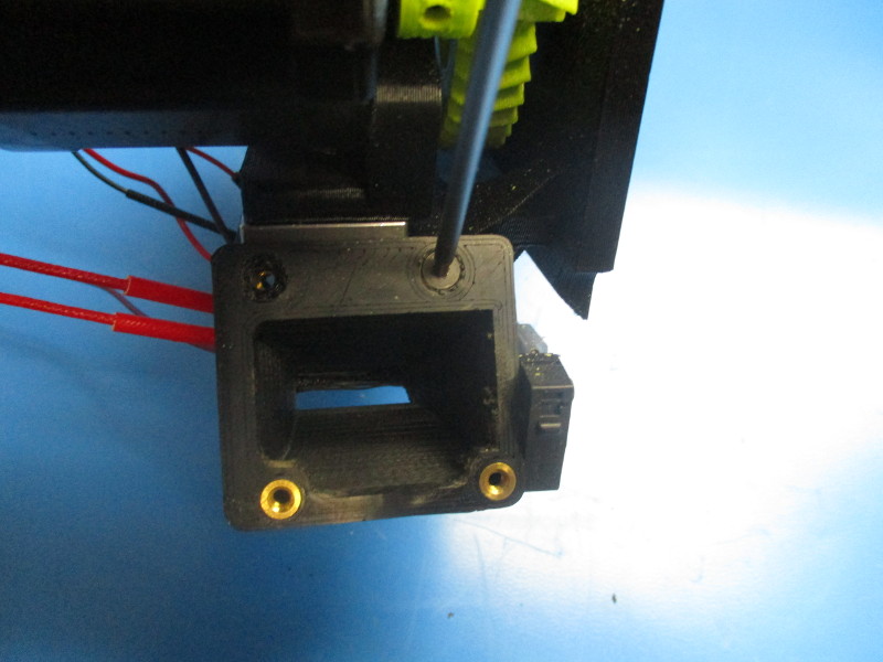
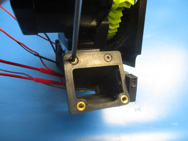
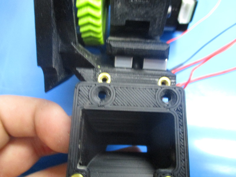
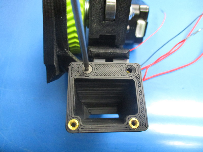
Press two M4 nuts into the lower pockets. (one on each side)
Install two M4 nuts into the upper pockets and press in if necessary.


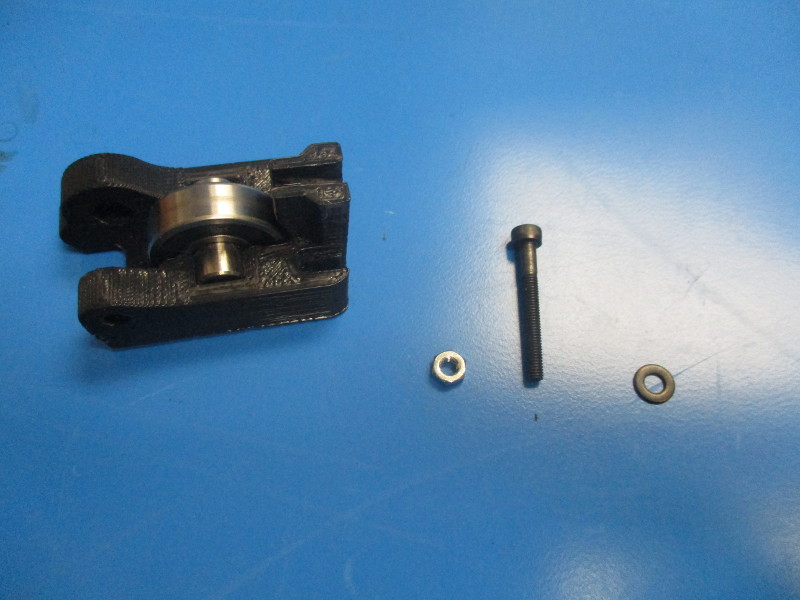
Gather parts
Extruder idler block (AS-TH0004)
M3x25 SHCS (HD-BT0041)
M3 nut (HD-NT0004)
M3 black oxide washer (HD-WA0038)
Instructions
Install the M3 nut into the pocket on the idler block.
Thread in the M3x35 SHCS with washer into the M3 nut
Gather parts
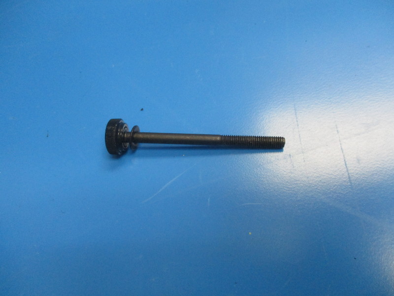
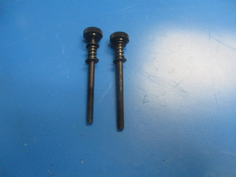
2x thumb screw (AS-TH0005)
2x extruder spring (HD-MS0027)
4x M4 black oxide washer (HD-WA0039)
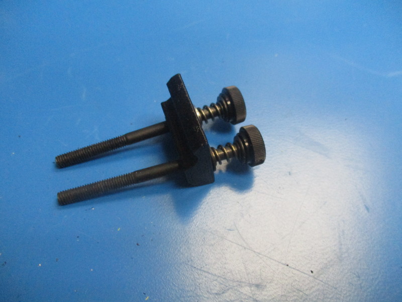
1x extruder latch (PP-GP0091)
Instructions
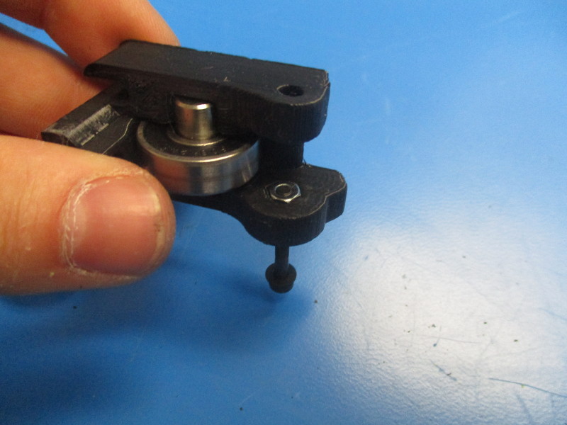
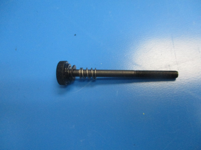
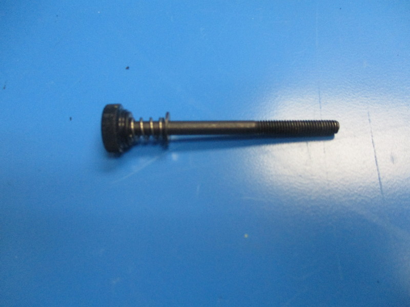
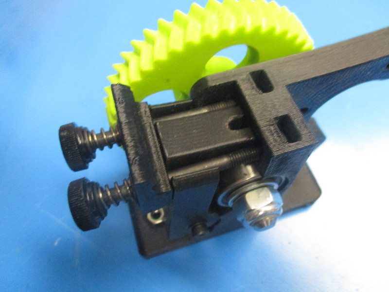
Install hardware onto the thumb screw in the order- washer, spring, washer.
Repeat process for second assembled thumb screw.
Install the thumb screws into the extruder latch. Note orientation of latch

Tools needed
2.5mm driver
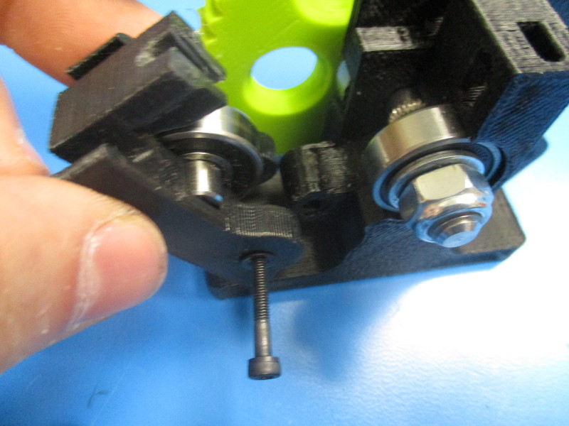
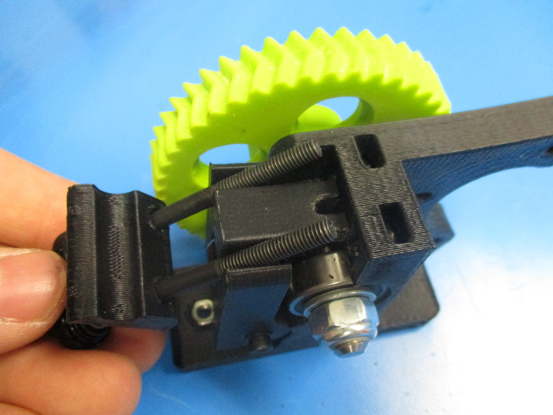
Align the idler block with the extruder body as shown in image “align with hinge”.
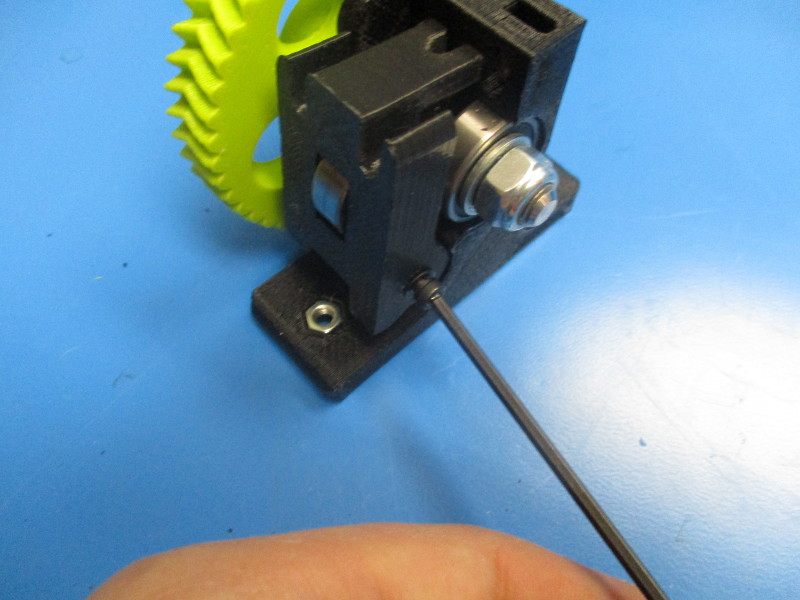
Install the idler block onto the extruder body. Tighten the M3x25 SHCS on the idler block to 3in*lbs.
Align and install the Extruder latch onto the extruder body. Thread into the upper two M4 nuts previously installed.
Gather parts
M3 nut (HD-NT0004)
M3 set screw (HD-BT0012)
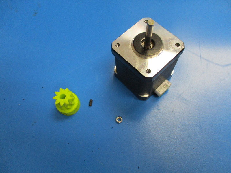
small herringbone gear (PP-GP0192)
Nema 17 motor (EL-MT0029)
Tools needed
1.5mm driver
Instructions
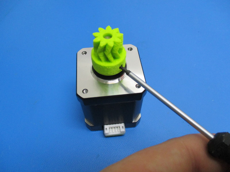
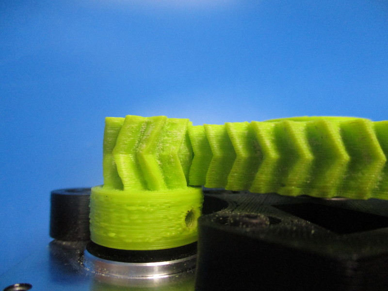
Start by laying the small herringbone gear is sitting with the nut slot facing up (see image for gear orientation)
Press nut into slot until holes in the small gear and the nut line up.
Rotate the gear so that the slot is facing down
Install the set screw into the hole that is aligned with the nut using a 1.5mm driver Tighten until the head of the set screw is flush with the plastic.
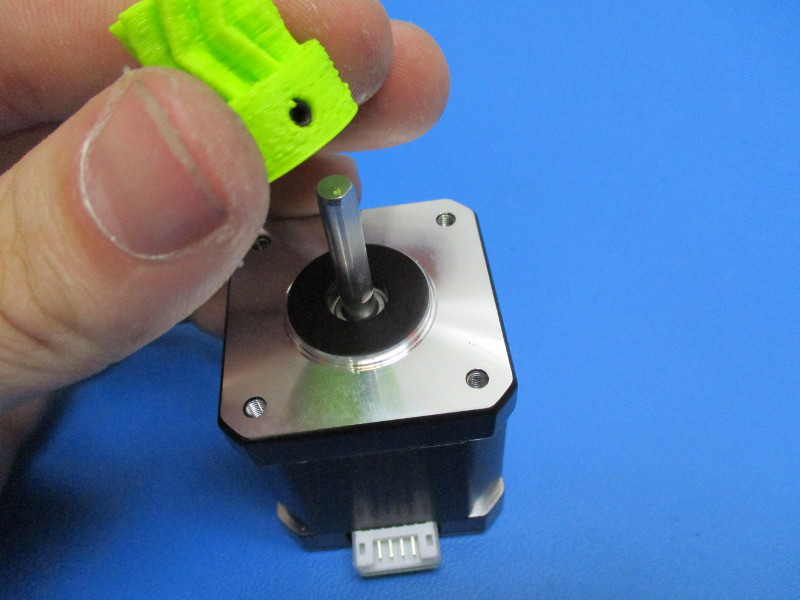
Install the small herringbone gear onto the shaft of the motor. Ensure that the set screw is aligned with the flat section of the shaft.
Finger tighten the set screw up to the shaft by using the 1.5mm driver.


Gather parts
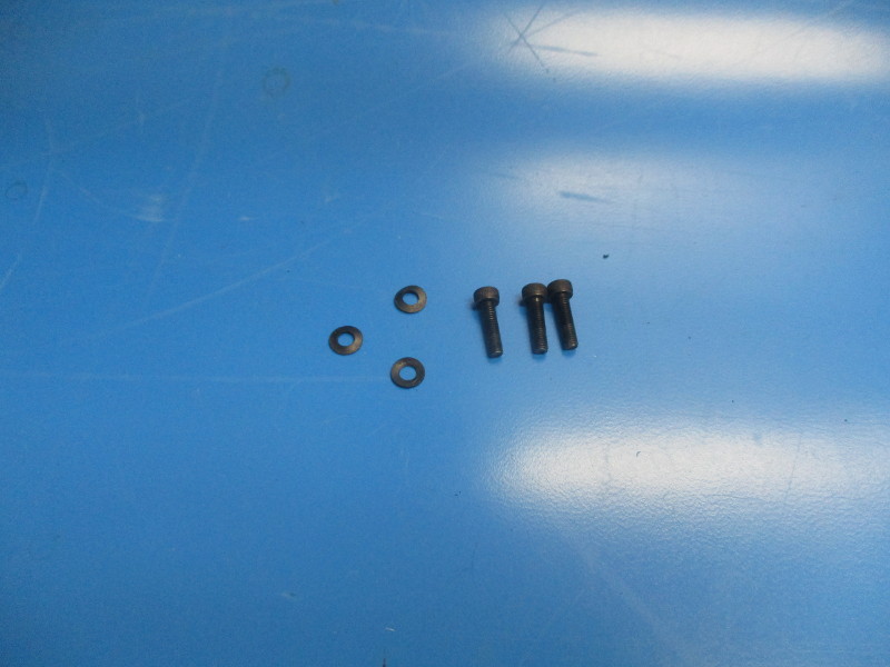
3x M3x12 SHCS (HD-BT0039)
3x M3 black oxide washer (HD-WA0038)
Tools needed
2.5mm driver
Instructions
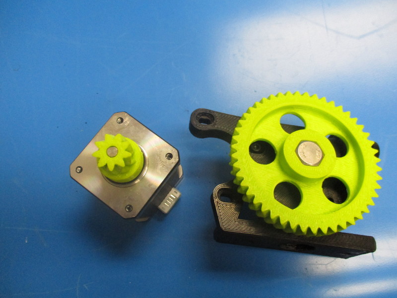
Mount the motor to the body (note the orientation of the motor and harness connection point)
Place the M3x12 SHCS with black oxide washers in the three holes that line up with the tapped holes in the motor
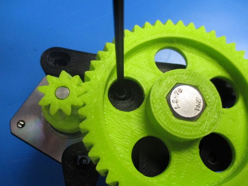
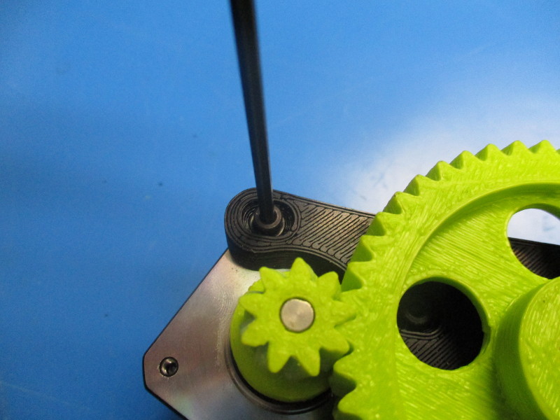
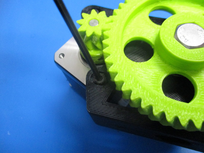
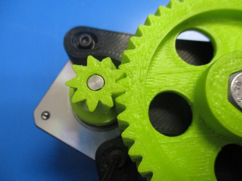
Note: the large gear and the small gear need to be mated together in a way that there is easy rotation but won't have any free movement known as “slap” between the gear teeth. To test for proper alignment of gears - tighten your screws down to 3 in/lbs, Hold the small gear firmly with your finger and thumb, and try to move the large gear back and forth to see if there is any small movement between the teeth of the gears. Rotate the large gear ¼ turn and repeat this process multiple times to ensure alignment. If there is movement the small gear and large gear need to be moved closer to each other. To do this you need loosen the M3 screws ¼ turn counter-clockwise and push the motor closer to the body. Repeat until you have desired the results, tighten screws once the fit is correct.) Once the gears are tight make sure the teeth of both gears line up with each other. If they are not lined up there will be more wearing of the gears then there would be if the teeth were lined up.
Tighten the set screw in the small herringbone gear to 3in*lbs
Gather parts
1x Extruder mount (AS-TH0015)
1x mount plate (PP-MP0156)
1x E3D, Hexagon Hot End, 0.5mm Copper Nozzle, 24V 30W Heater (HE-SH0049)
2x M4x20 SHCS (HD-BT0010)
2x M4 black oxide washer (HD-WA0039)
1x Extruder body sub assembly (previously assembled)
Tools needed
150mm of 3mm filament
3.5mm driver
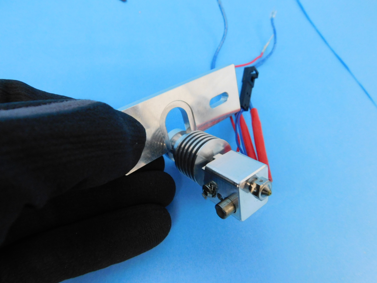
Instructions
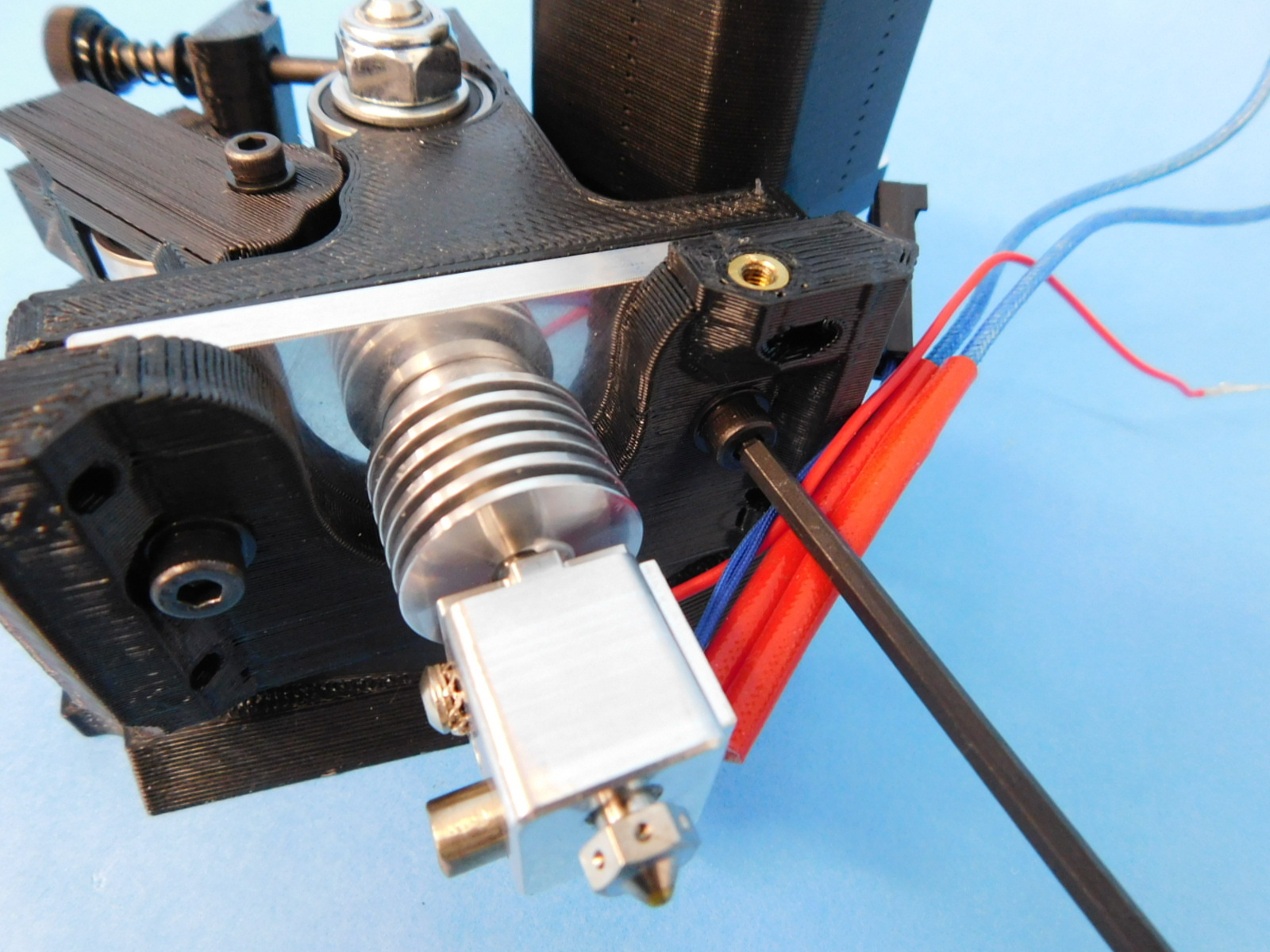
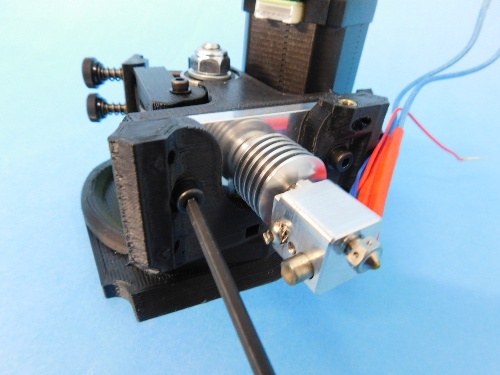
Slide the mount plate over the grooved section of the heat sink on the hot end.
Take the hot end with the mount plate attached and slide it onto the extruder mount.
Place the extruder body onto the hot end so that all the holes align. Feed the piece of filament in to ensure extruder body to hot end alignment.
Insert M4x20 screws with M4 washers into the holes in the front of the extruder mount and through the slots in the mount plate into the M4 nuts and tighten to 8in*lbs. Check the heater block to ensure it is aligned with the mount plate.
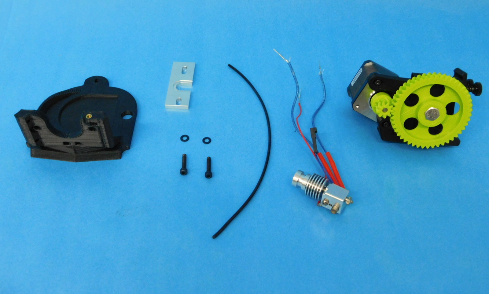

Gather parts
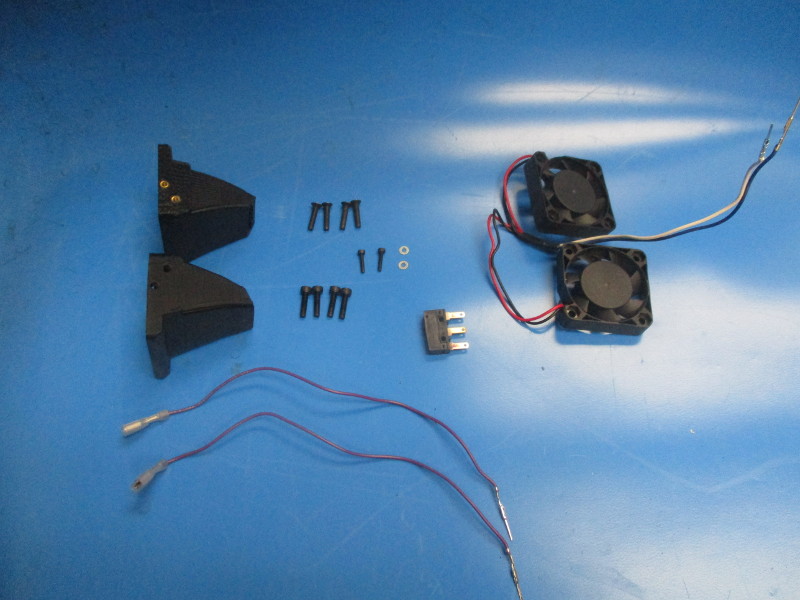
1x cable tie (HD-MS0058)
1x fan duct left (AS-TH0017)
1x fan duct right (AS-TH0018)
1x extruder fan harness (EL-HR0095)
1x end stop switch (EL-SW0022)
2x end stop switch harness (AS-CB0006)
2x M2x10 SHCS (HD-BT0107)
2x M2 SST washer (HD-WA0012)
4x M3x12 SHCS (HD-BT0039)
4x M3x14 FHCS (HD-BT0118)
Tools needed
2.5mm driver
2mm driver
1.5mm driver
Flush cutters
Instructions
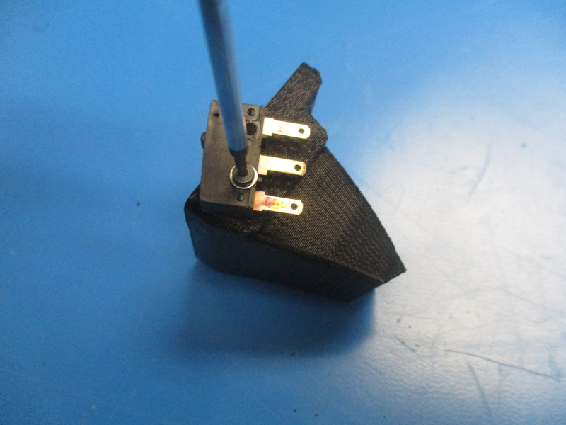
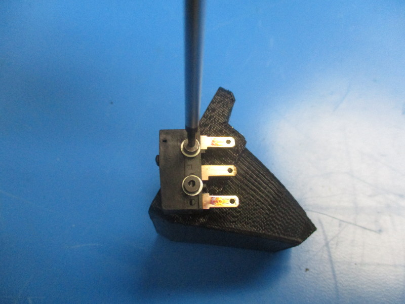
Align the holes in the end stop switch with the small threaded inserts on the side of the right fan mount. Install the M2x10 screws to attach the switch to the fan mount, torque to 2in*lbs
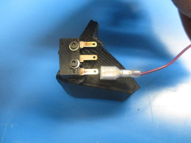
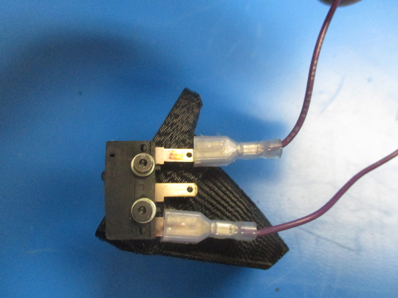
Attach the switch harness wires to the bottom prong and top prong
Line up the counter sunk holes on the right fan duct with the threaded inserts on the right of the extruder mount.
Attach the right fan duct to the extruder mount with the M3x14 FHCS using the 2mm hex driver. Torque to 3in*lbs
Locate the left side of the extruder mount to attach the left fan duct. Align the counter sunk holes in the fan duct with the threaded inserts on the extruder mount. Attach the fan duct using two M3x14 FHCS and torque to 3in*lbs.
Attach the fans to the fan ducts.
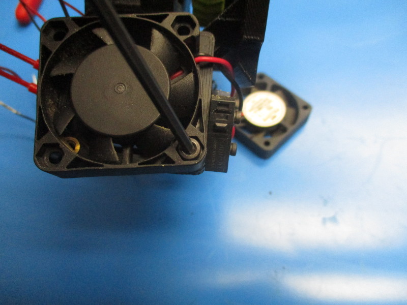
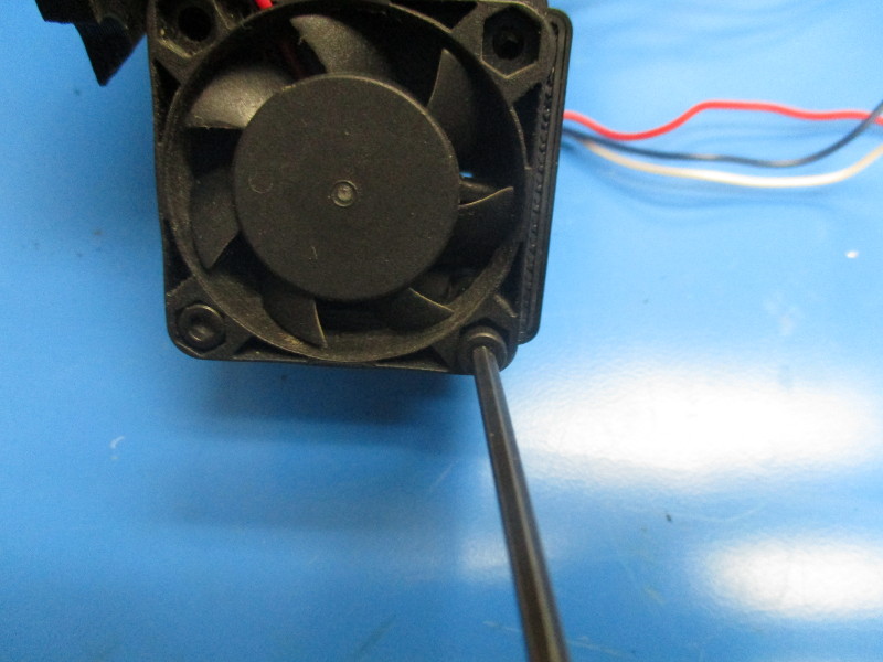
The fan with the sort wires will be attached on the right fan duct. Ensure the correct fan orientation so the black and red wires are coming out of the top right side when looking at the right side of the extruder. Torque to 5in*lbs
Attach the fan with the long wires to the left fan duct using two M3x12 SHCS. Torque to 5in*lbs
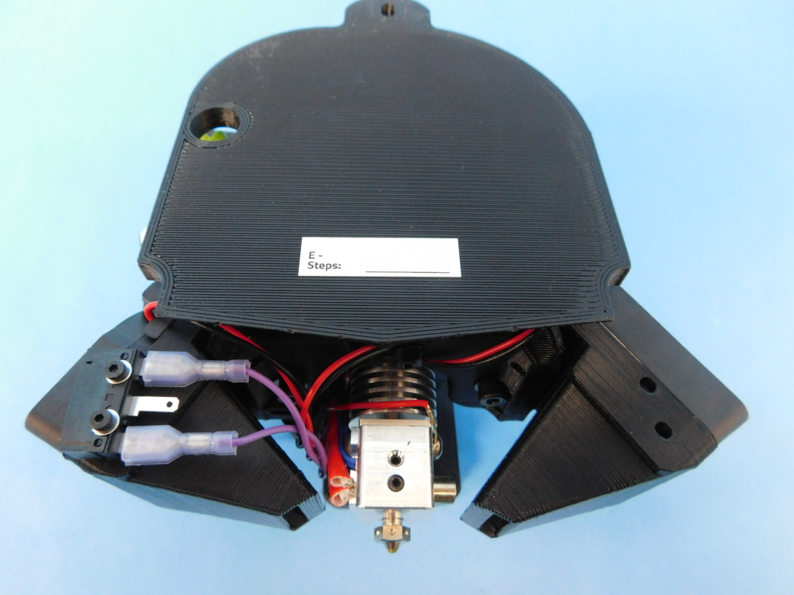
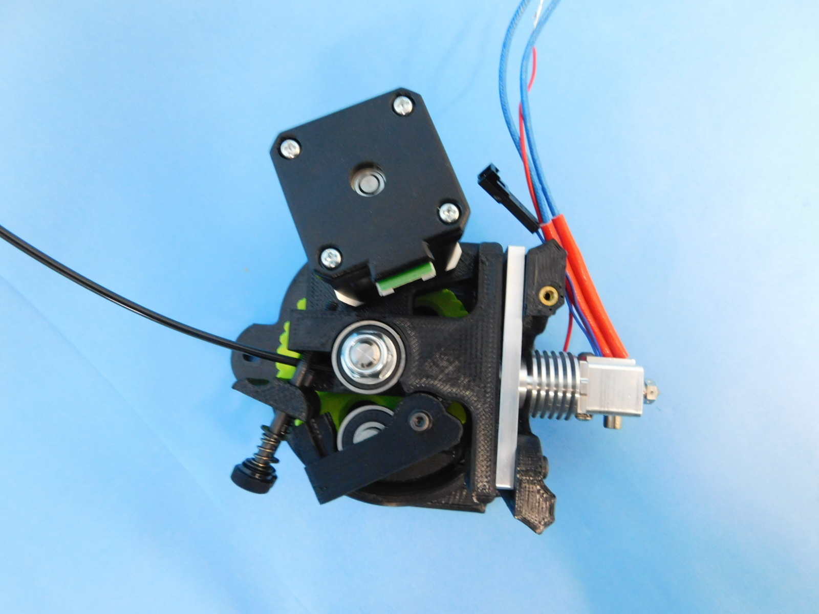
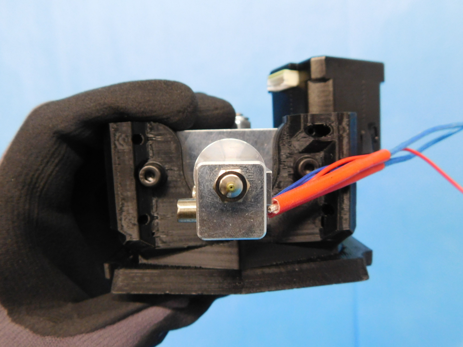
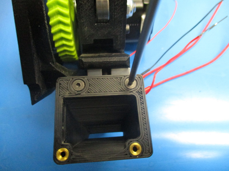
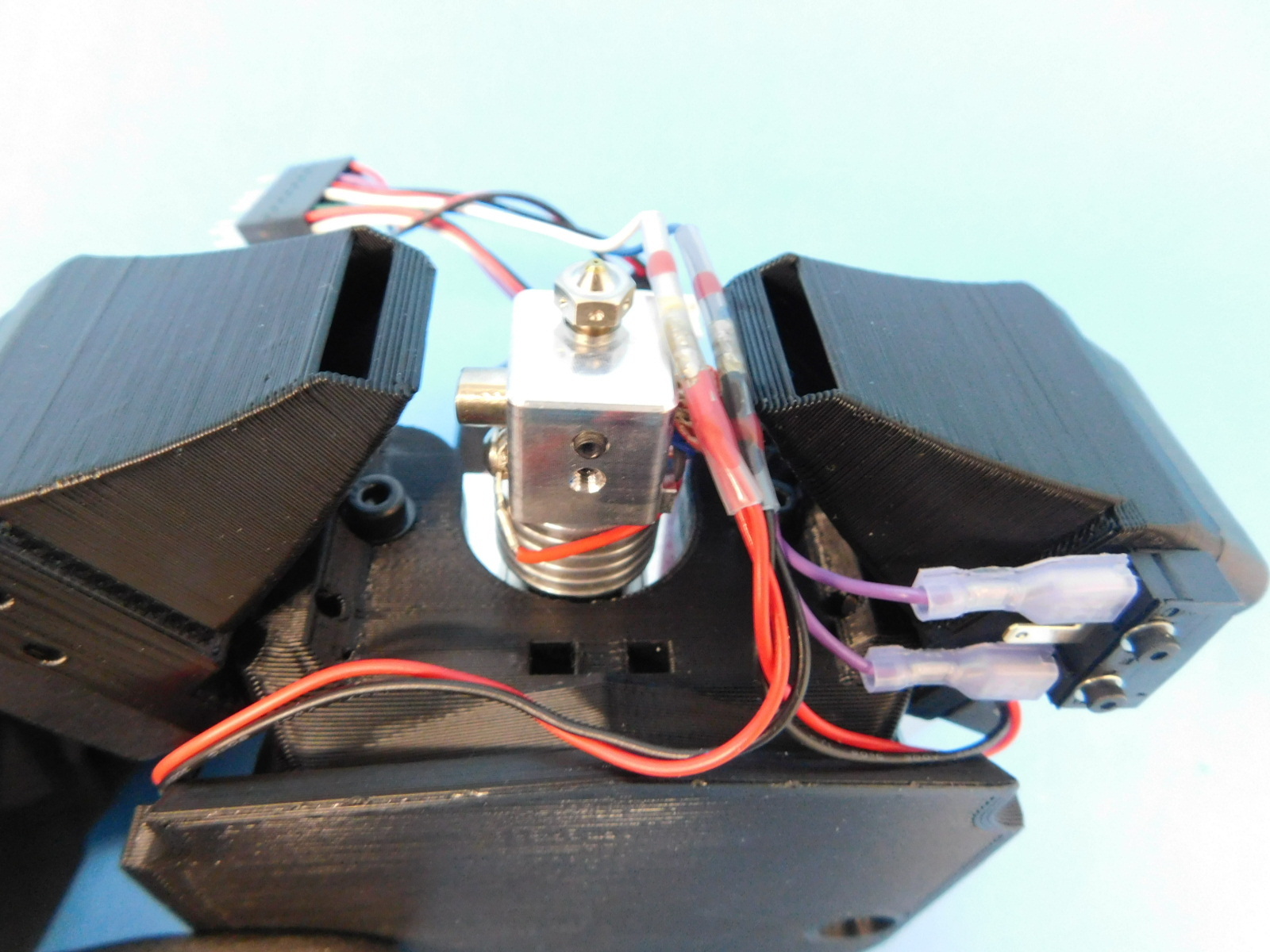
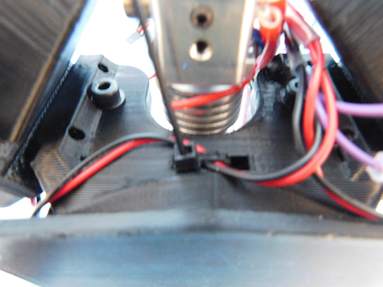
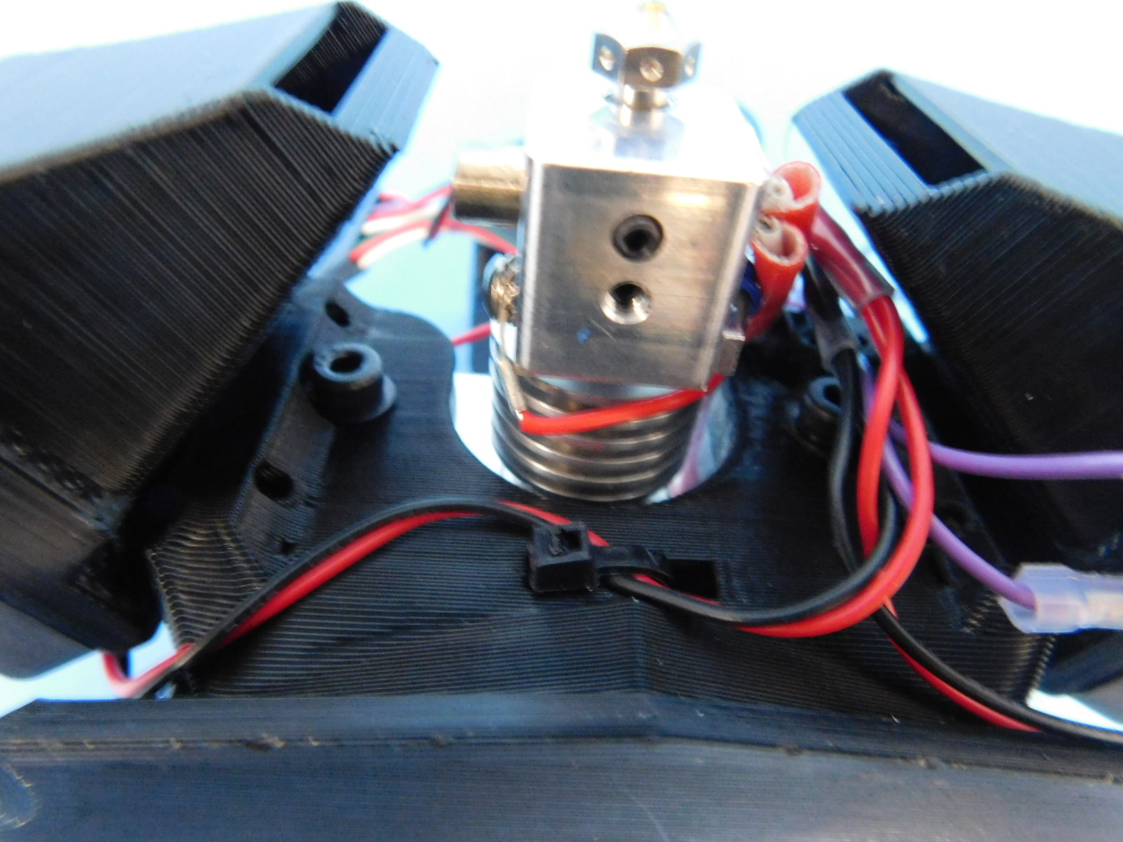
Tilt the extruder assembly so the nozzle is pointing upward. Route the fan harness and the end stop switch harnesses between the heater block and the right fan duct. Pull snug. Cable tie the fan harness to the extruder mount using the pocket located behind the hot end. Clip off the excess cable tie.
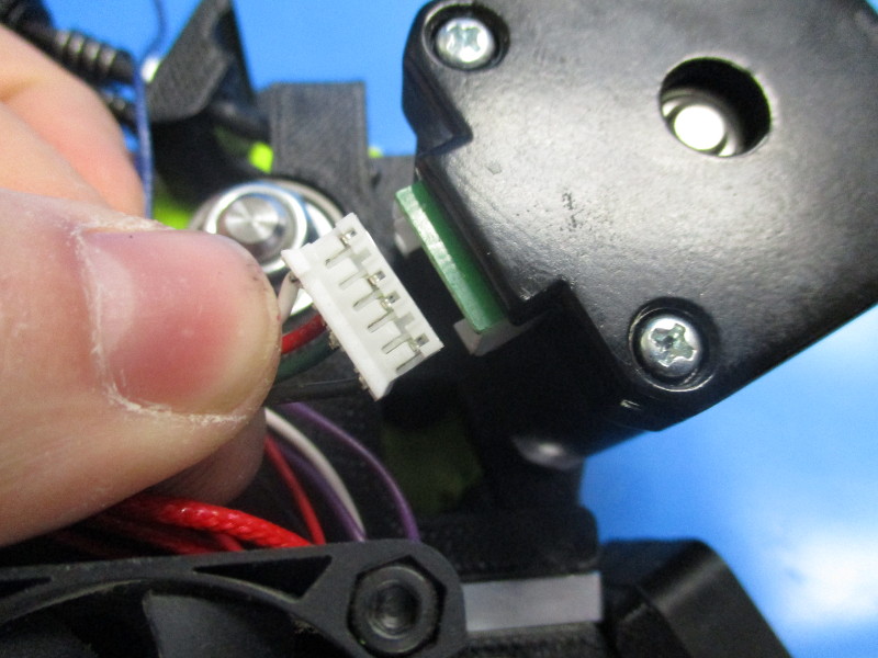
Lay the extruder assembly on its back. Pull all of the harnesses up past the motor.


Gather parts
4x M3x12 SHCS (HD-BT0039)
1x- M3x25 SHCS (HD-BT0041)
1x M3 black oxide washer (HD-WA0038)
1x Heat sink fan mount (AS-TH0075)
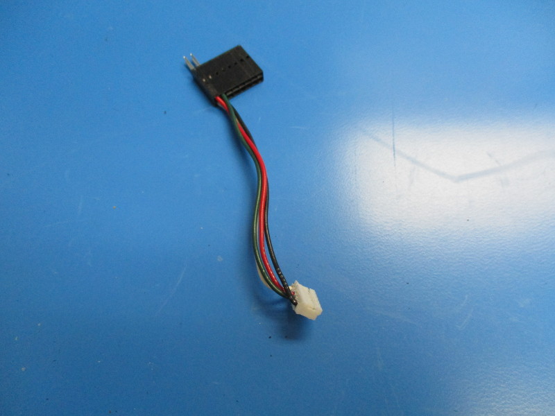
1x heat sink 5v fan harness (AS-CB0005)
Tools needed
2.5mm driver
Instructions
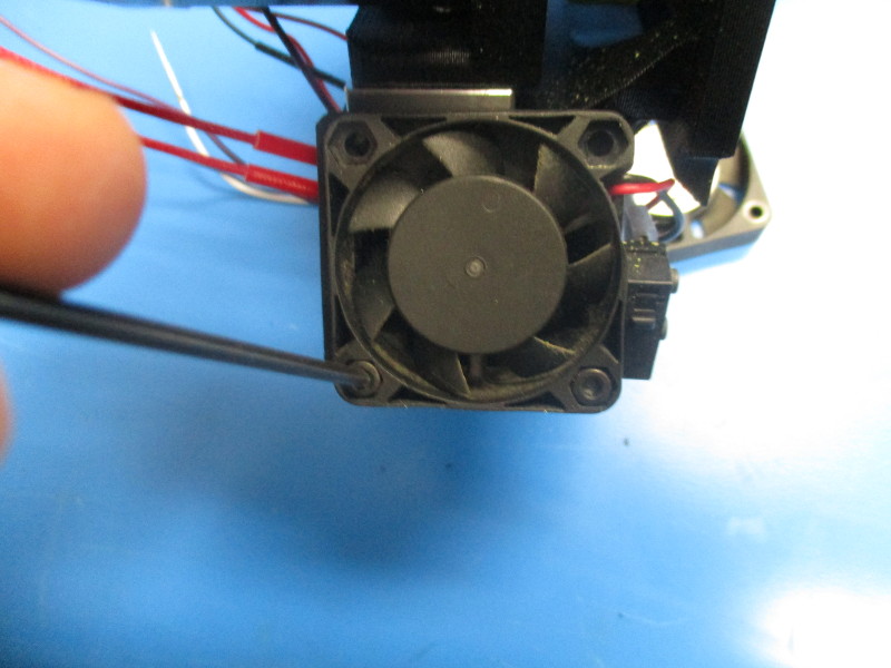
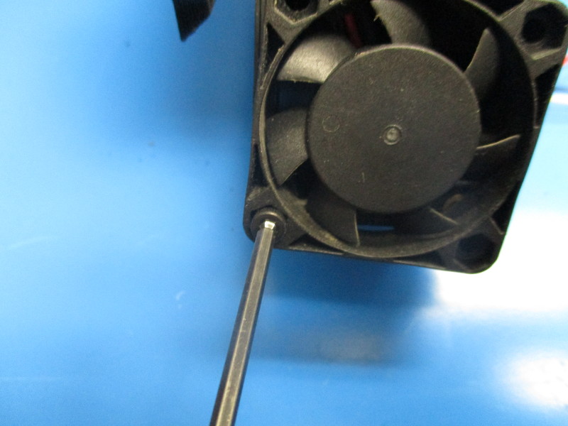
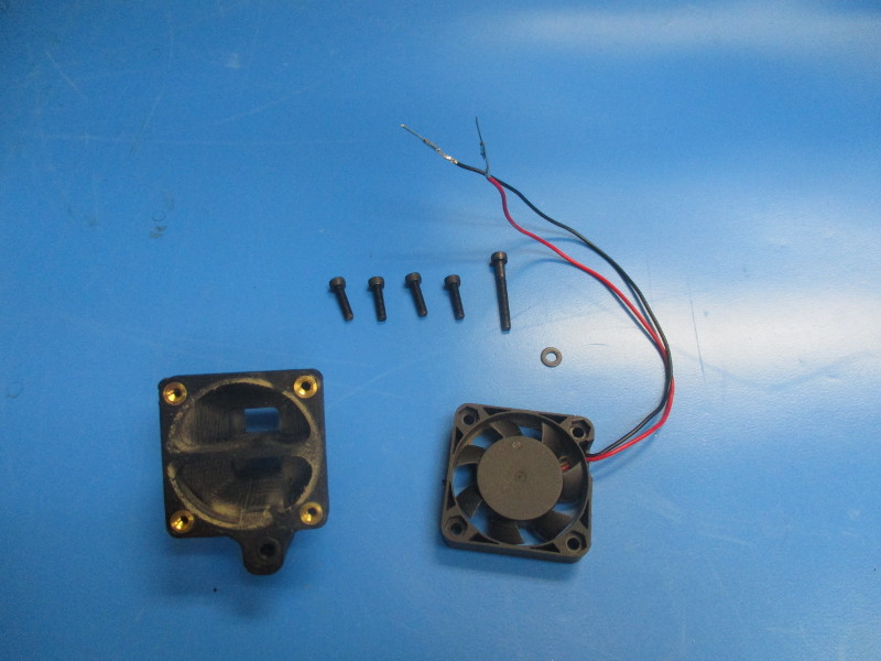
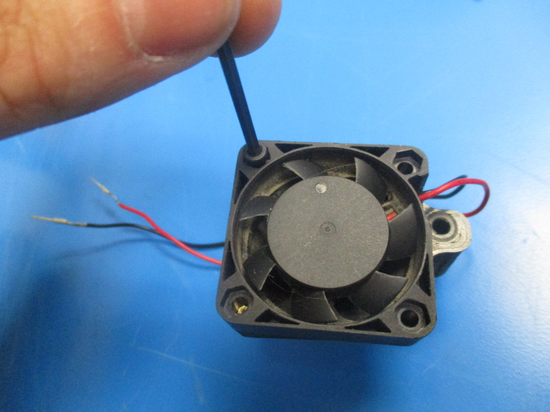
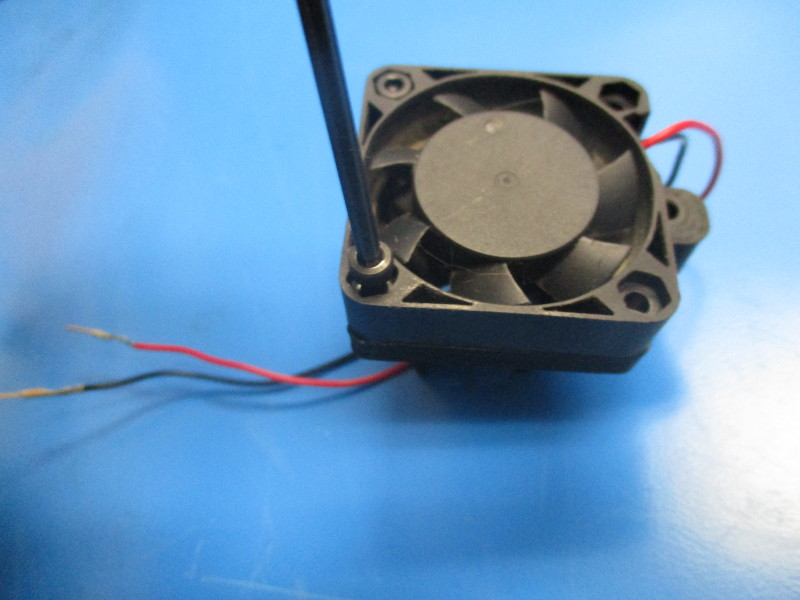
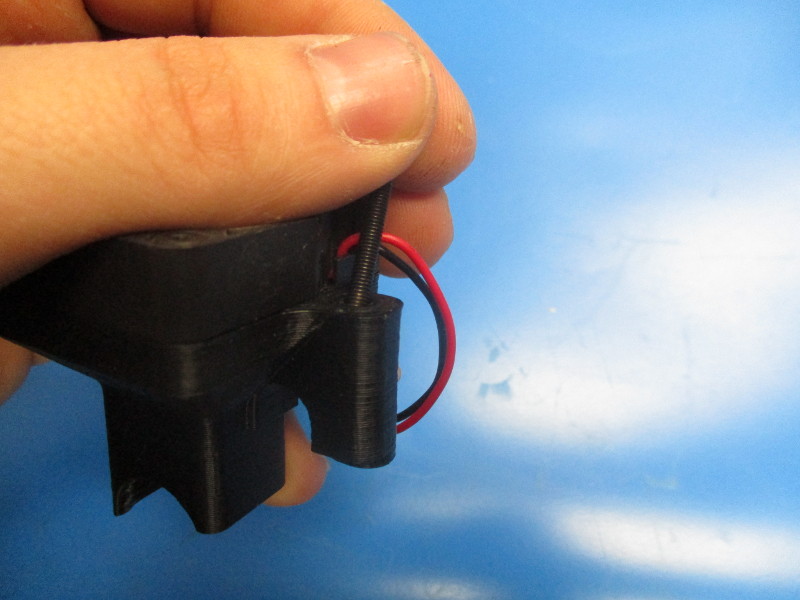
Place the fan onto the heat sink fan mount so that the holes align with the threaded inserts. Ensure the correct fan orientation seen in image “fan orientations and tighten”
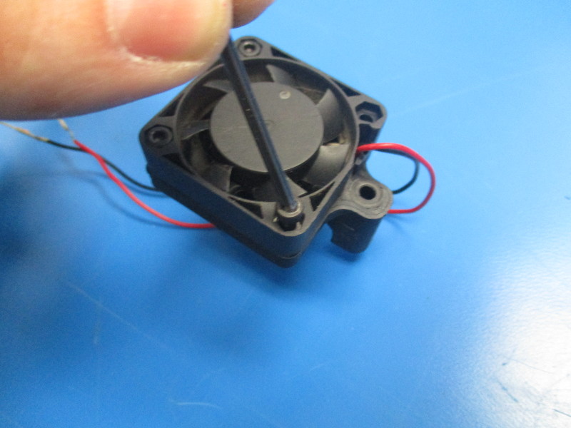
Secure the fan with four M3x12 SHCS and torque to 5in*lbs Install the M3x25 SHCS in the side hole of the fan duct. Route the fan cable over the side hole, then down the plastic part and under.
The heat sink fan duct will sit on the heat sink of th ehot end. Align the M3x25 SHCS with the threaded insert on the extruder mount next to the heat sink and torque down to 2in*lbs.


Gather parts
Instructions
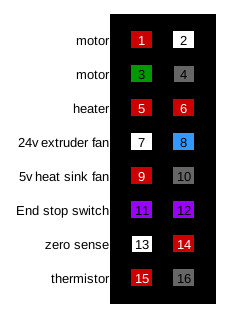
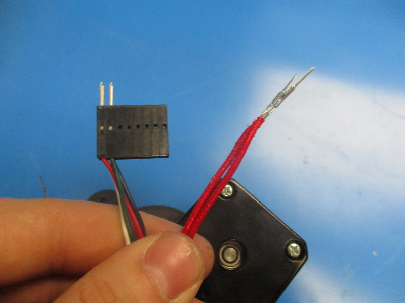
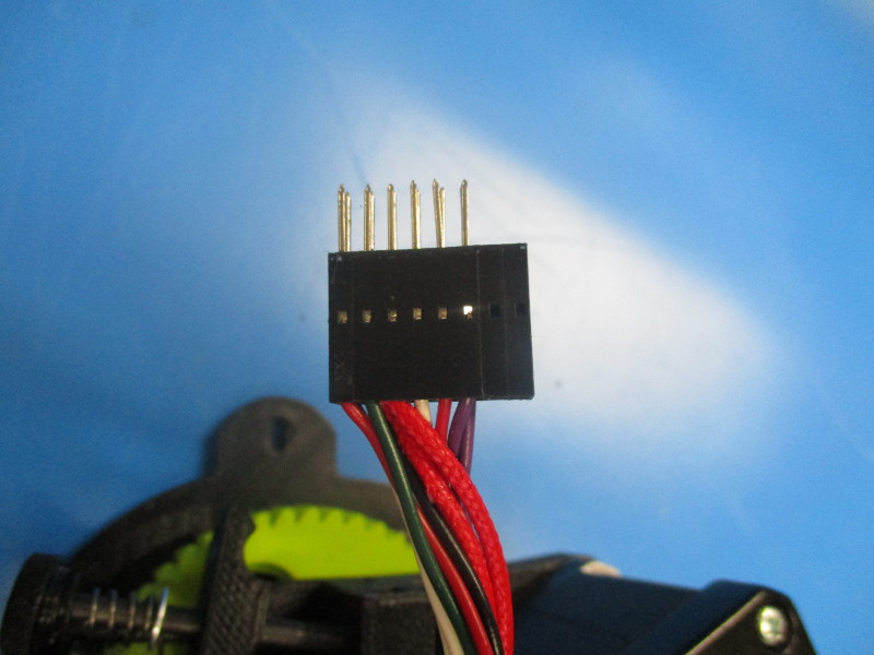
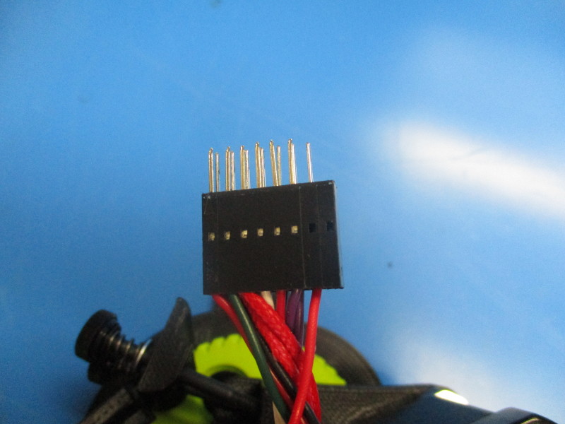
Wrap the heater cartridge harness helically around the RevB Stepper Motor JST 115mm Harness twice then connect to pin position 5 and 6.
Wrap the 24v extruder fan harness helically once around the RevB Stepper Motor JST 115mm Harness and connect the white wire to pin position 7 and the blue wire to position 8.
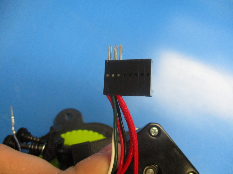
Run the 5v heat sink fan parallel to theRevB Stepper Motor JST 115mm Harness and connect the red wire into pin position 9 and the black wire into pin position 10.
Wrap the end stop switch harness helically around the RevB Stepper Motor JST 115mm Harness two times and connect in pin position 11 and 12.
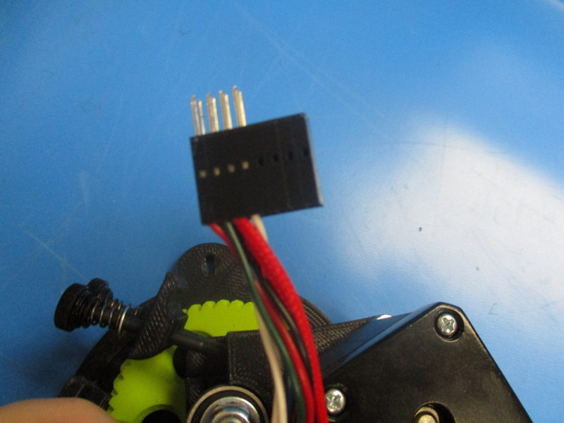
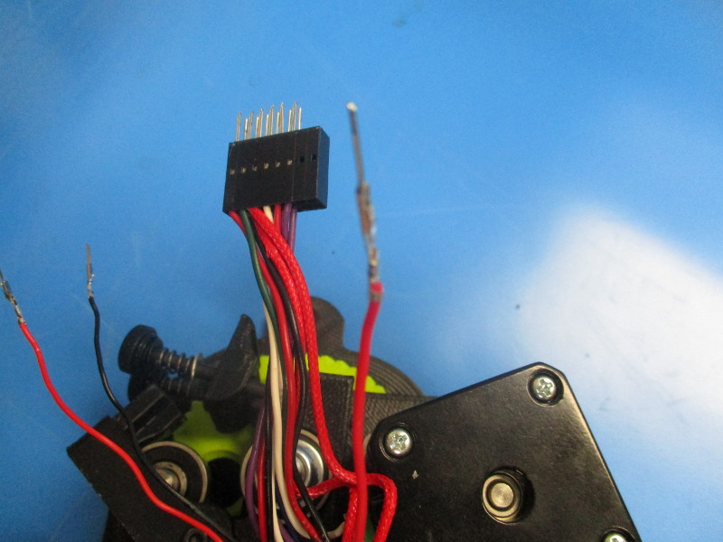
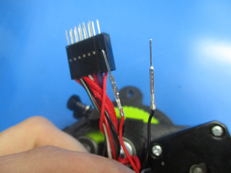
Run the thermistor wires parallel to the RevB Stepper Motor JST 115mm Harness and connect the red wire to pin position 15 and the black wire in pin position 16.
Wrap the zero volt sense harness once helically around the RevB Stepper Motor JST 115mm Harness and connect into pin position 14.


Gather parts
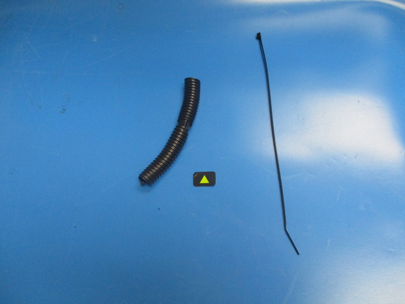
100mm Panduit (EL-MS0139)
Cable tie (HD-MS0058)
arrow direction sticker (DC-LB0104)
Tools needed
Flush cutters
Instructions
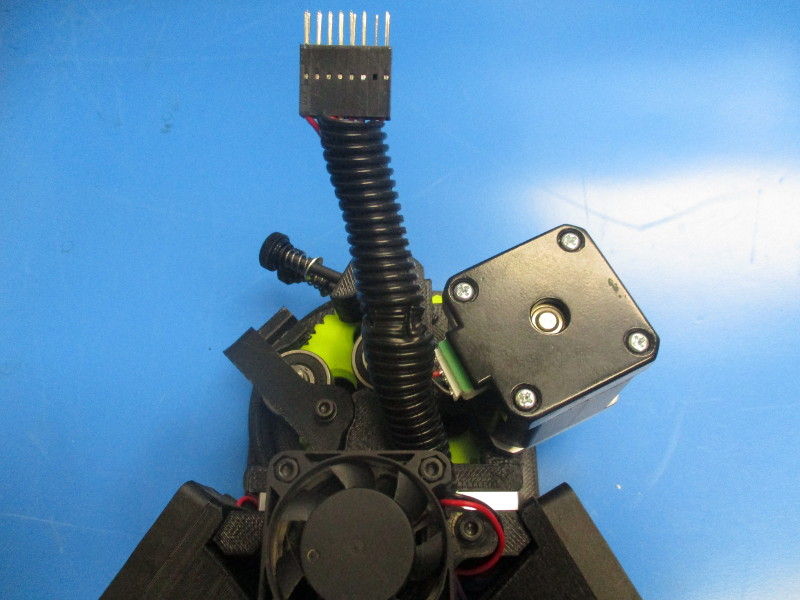
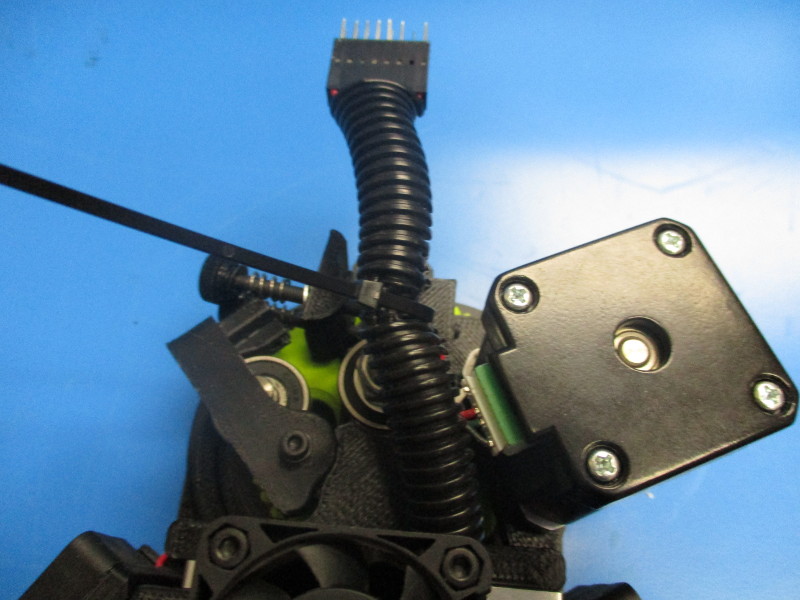
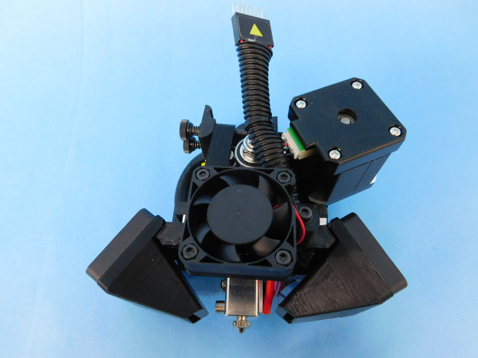
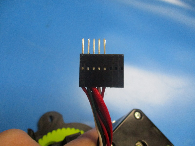
Slide the panduit onto the harnesses. Ensure all of the harnesses are secured in the panduit. Cable tie the panduit closed half way up the panduit. Clip off the the excess cable tie.
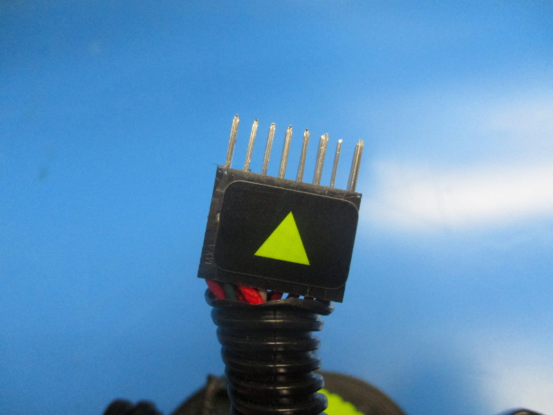
Apply the arrow direction sticker to pin one side of the 16 pin connector ( arrow side)