Open HardwareAssembly Instructions
Guides for installation and assembly of the LulzBot line of products made by FAME 3D LLC.
Guides for installation and assembly of the LulzBot line of products made by FAME 3D LLC.
!WARNING! The firmware and g-code for this test fixture are intended to be used on the test fixture only. DO NOT use the firmware or g-code on a completed TAZ 6 or damage will result!
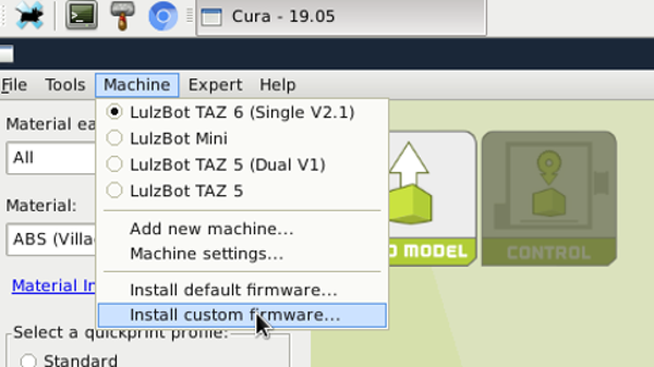
Flash the control box with control box test firmware found here by using CURA. In CURA go to machine settings and select install custom firmware. Select the hex file found at the link above. You will need to have this file saved locally, and may need to rename it as a .hex file after download, if you cannot download, then copy all text to a text editor and save as a .hex file. Turn on the control box, select the file and flash. Wait for CURA to show flash successful. Turn off control box and disconnect.
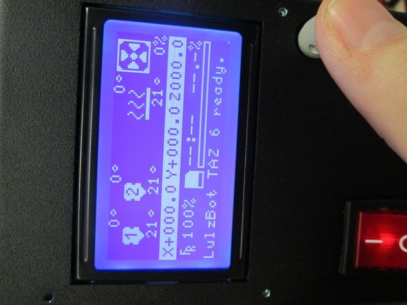
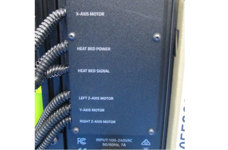
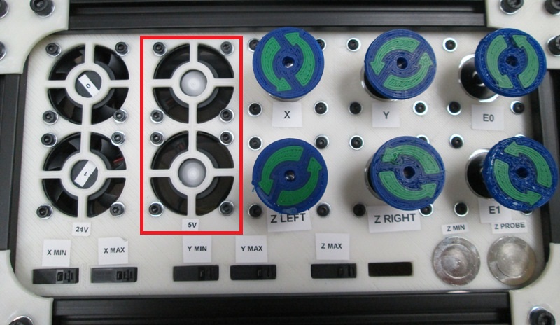
Plug the control box cables into the test fixture accordingly with the exception of the secondary extruder cable and switch on the control box. Verify the firmware at the splash screen. Powered on with only the secondary extruder cable unplugged, the top 5V fan should be the only fan spinning . There should be a "MIN TEMP" error on the LCD screen. Check to make sure extruder 2 reads 0 degrees then proceed. Turn the control box off, plug in the secondary extruder cable. power back on and continue. The 5V fans should both be spinning now and will remaining spinning throughout the test.
Insert an SD card containing the test G-code into the SD card reader. You will need to paste this file in a text editor and save as a .gcode file.
Press the encoder (control knob) located on the control box front near the display and and scroll to “Print from SD”; Select “TAZ6_control_box_test_0.3.gcode”
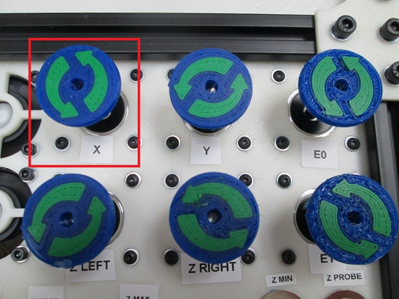
The test begins with the X motor beginning to spin to the left (Counter Clockwise or CCW).
The display will indicate “PUSH THE X MIN SWITCH”; Locate and Press the “X Min” switch on the test fixture; the X motor will start to turn right (Clockwise or CW);
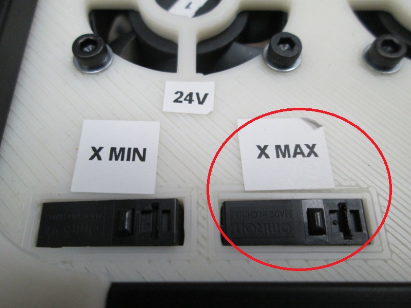
The display will indicate “PUSH X MAX SWITCH”;
Locate and Press the “X MAX” switch on the test fixture; the X motor will stop spinning and the Y motor will start to turn left;
Press the X max switch (move to the next step)


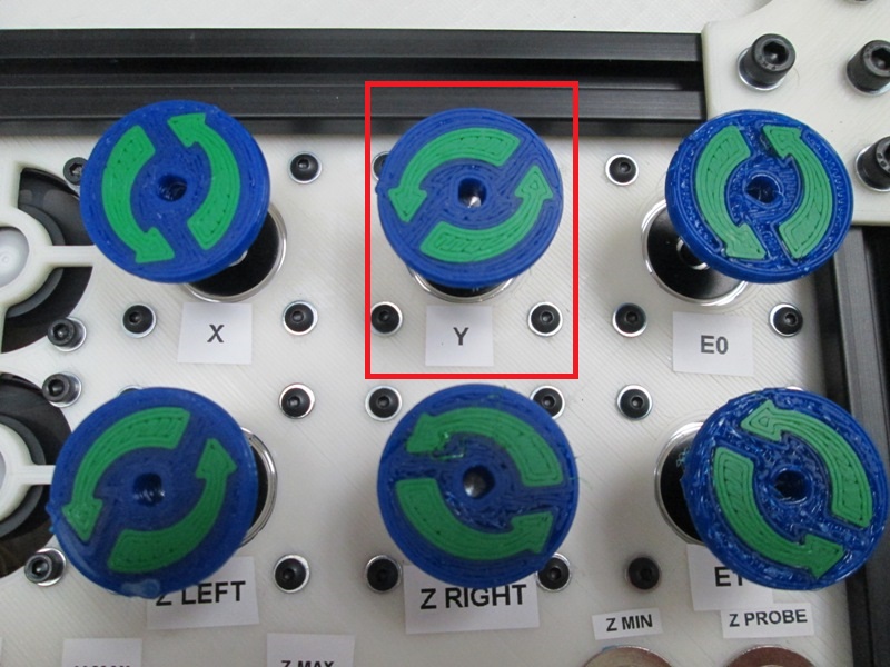
The Y motor should be turning to the left.
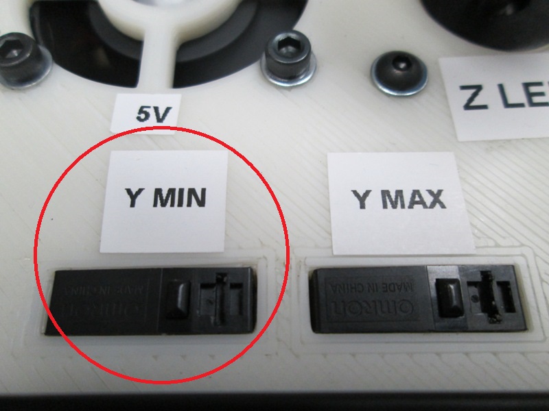
The display will indicate “PUSH THE Y MIN SWITCH”; Locate and Press the “Y MIN” switch on the test fixture; the X motor will start to turn right;
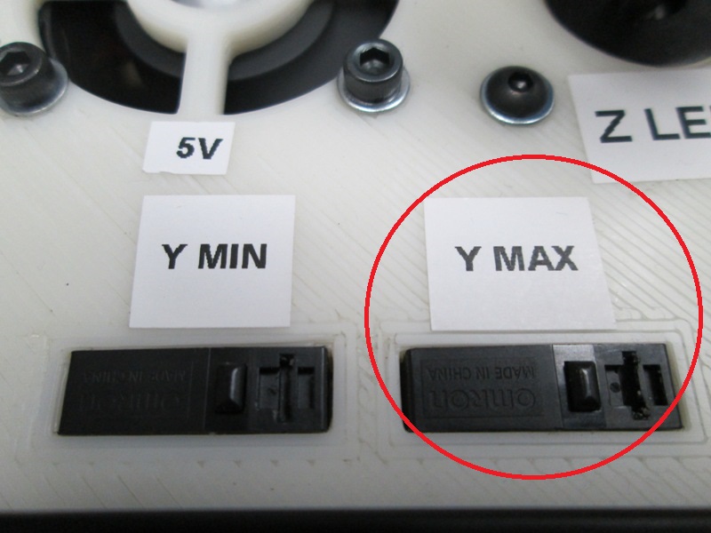
The display will indicate “PUSH Y MAX SWITCH”; Locate and Press the “Y MAX” switch on the test fixture; the Y motor will stop spinning and the Z motors will start to turn left;

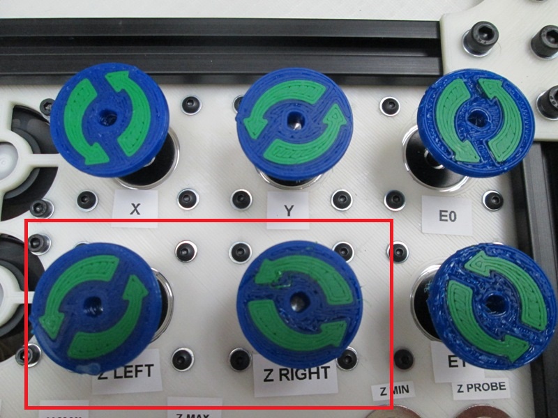
The Z motors should both be turning to the left.
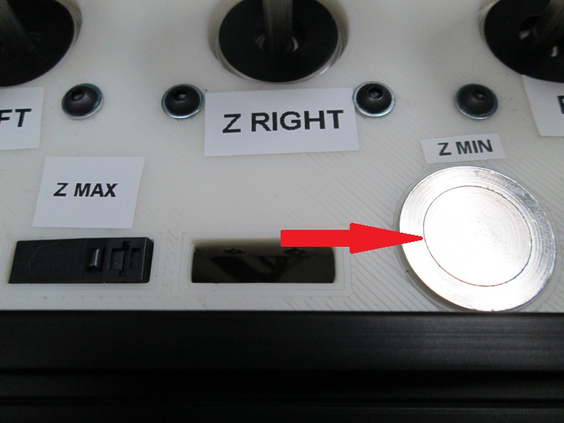
The display will indicate “PUSH THE Z MIN BUTTON”; Locate and Press the “Z MIN” button on the test fixture; the Z motors will start to turn right;
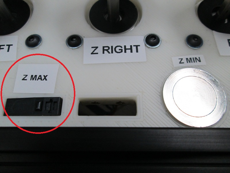
The display will indicate “PUSH Z MAX SWITCH”; Locate and Press the “Z MAX” switch on the test fixture; the Z motors will stop spinning;

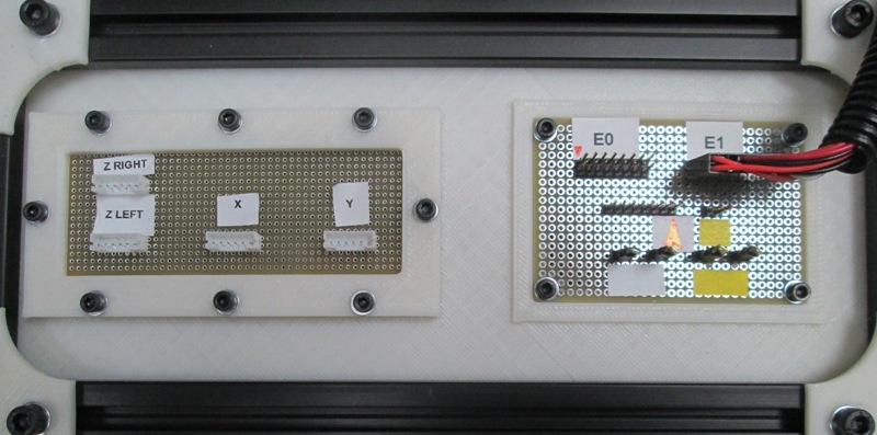
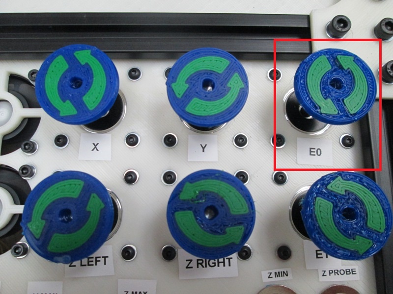
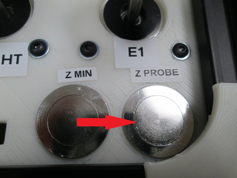
The display will indicate “PUSH THE Z PROBE BUTTON”; Locate and Press the “Z PROBE” button on the test fixture; the E0 motor will briefly turn to the Left;
The display will indicate “PUSH THE Z PROBE BUTTON”; Locate and Press the “Z PROBE” button on the test fixture; the E0 motor will briefly turn to the Right;


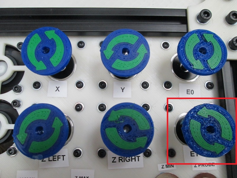
The display will indicate “PUSH THE Z PROBE BUTTON”; Locate and Press the “Z PROBE” button on the test fixture; the E1 motor will briefly turn to the Left;
The display will indicate “PUSH THE Z PROBE BUTTON”; Locate and Press the “Z PROBE” button on the test fixture; the E1 motor will briefly turn to the Right;


The 24VDC fans will immediately begin to turn;
The display will indicate “FANS 40 PERCENT”; verify that both 24V fans are spinning at medium speed for approximately 10 seconds;
The fans will start to spin at a high speed for approximately 10 seconds and the display will indicate “FANS 100 PERCENT”; verify both fans have a high spin rate;
The fans will turn off and the display will indicate “PRESS ENCODER”; Locate and Press the encoder on the unit under test, there will be a beep from the control box signaling the test has been completed and was successful. The display will now indicate “Test successful!!!”
Press encoder
After the test was run successfully turn off the control box. When the control box is turned back on the the Splash screen should display “Test Successful!!!” and the display should indicate “Test Successful!!!” this is stored in the EPROM to ensure the box was tested successfully and will be erased when the control box is flashed with the latest TAZ6 firmware.