Open HardwareAssembly Instructions
Guides for installation and assembly of the LulzBot line of products made by FAME 3D LLC.
Guides for installation and assembly of the LulzBot line of products made by FAME 3D LLC.
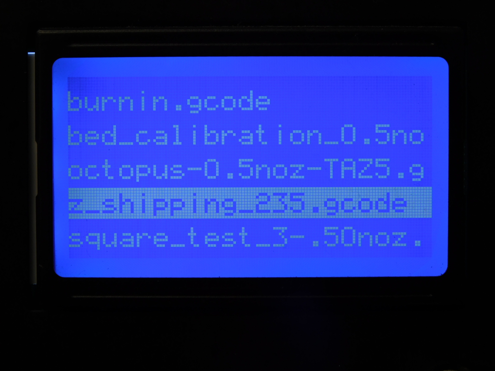
Please set the tool head to the Z-shipping position. To get the gcode for this. Please visit this site.
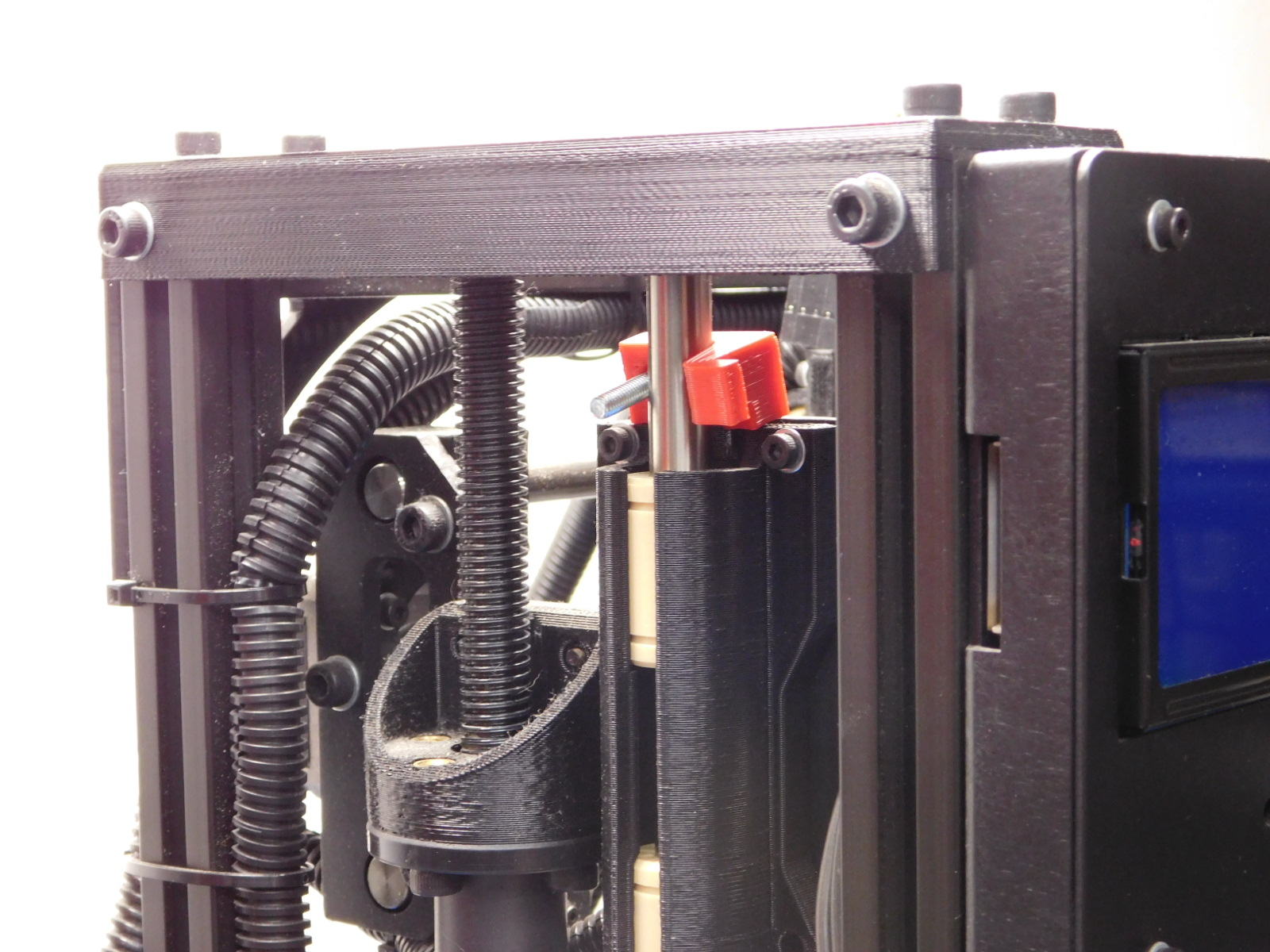
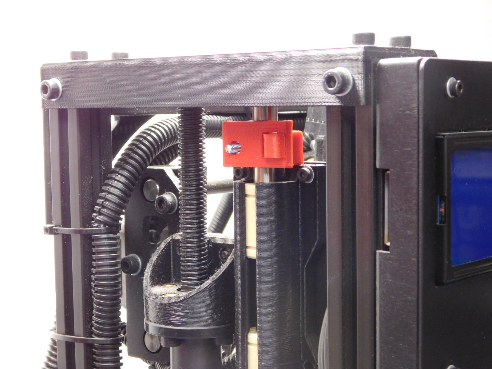
Proceed to attach the shipping clamps, if you still have them. If not you may skip this step and move to taping the endstops.
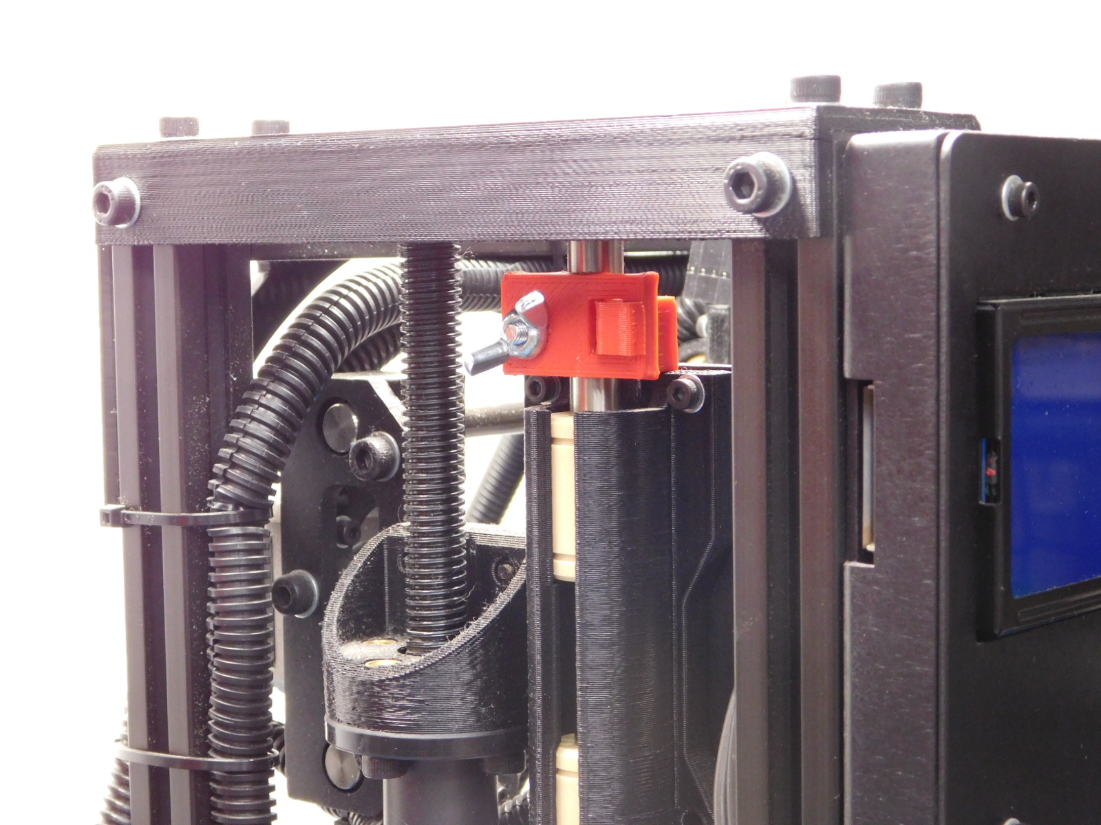
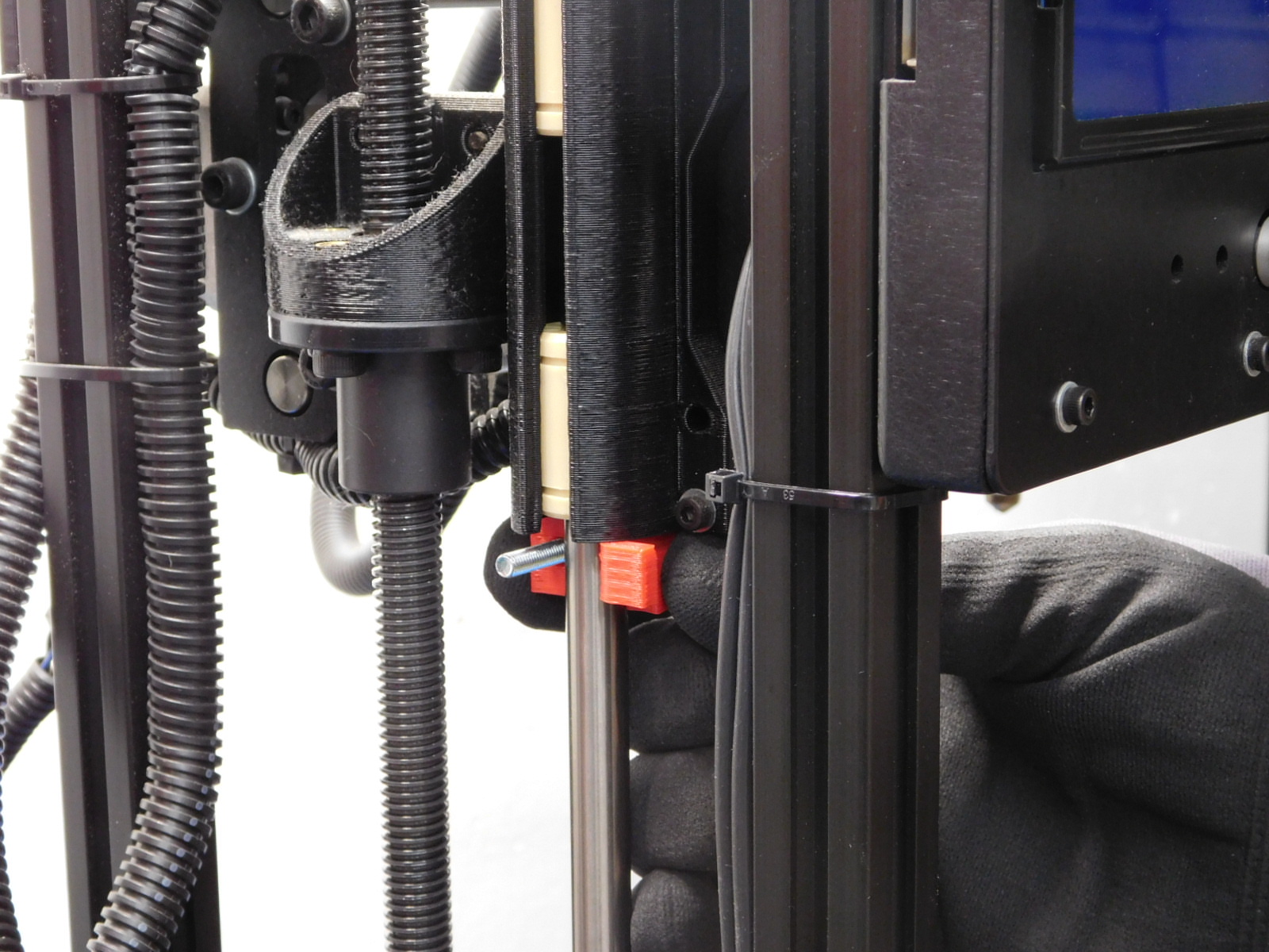
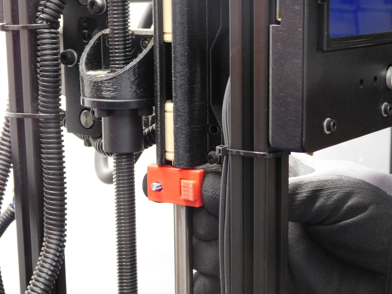
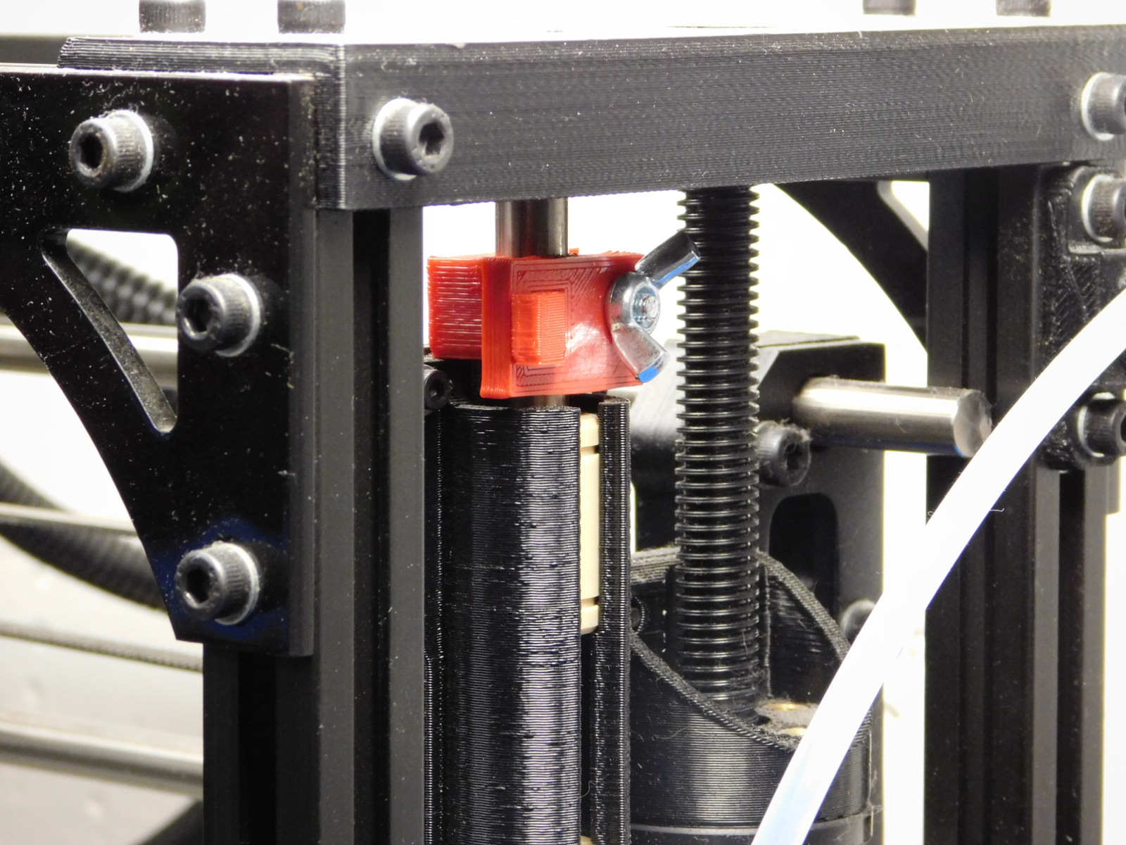
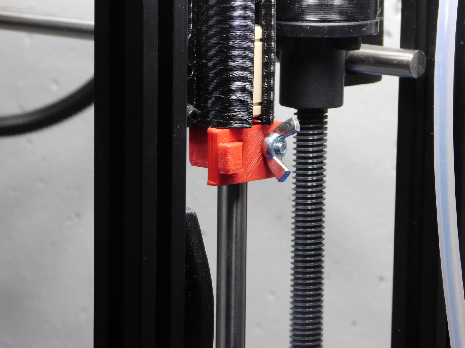
Place the shipping clamp "B" on the smooth rod with the threads of the screw facing out.
Take shipping clamp "A". Hook clamp "A" to "B" and latch it over the threads.
Secure both clamps with a wing nut
Repeat steps for left and right side of TAZ 5 (see photos)

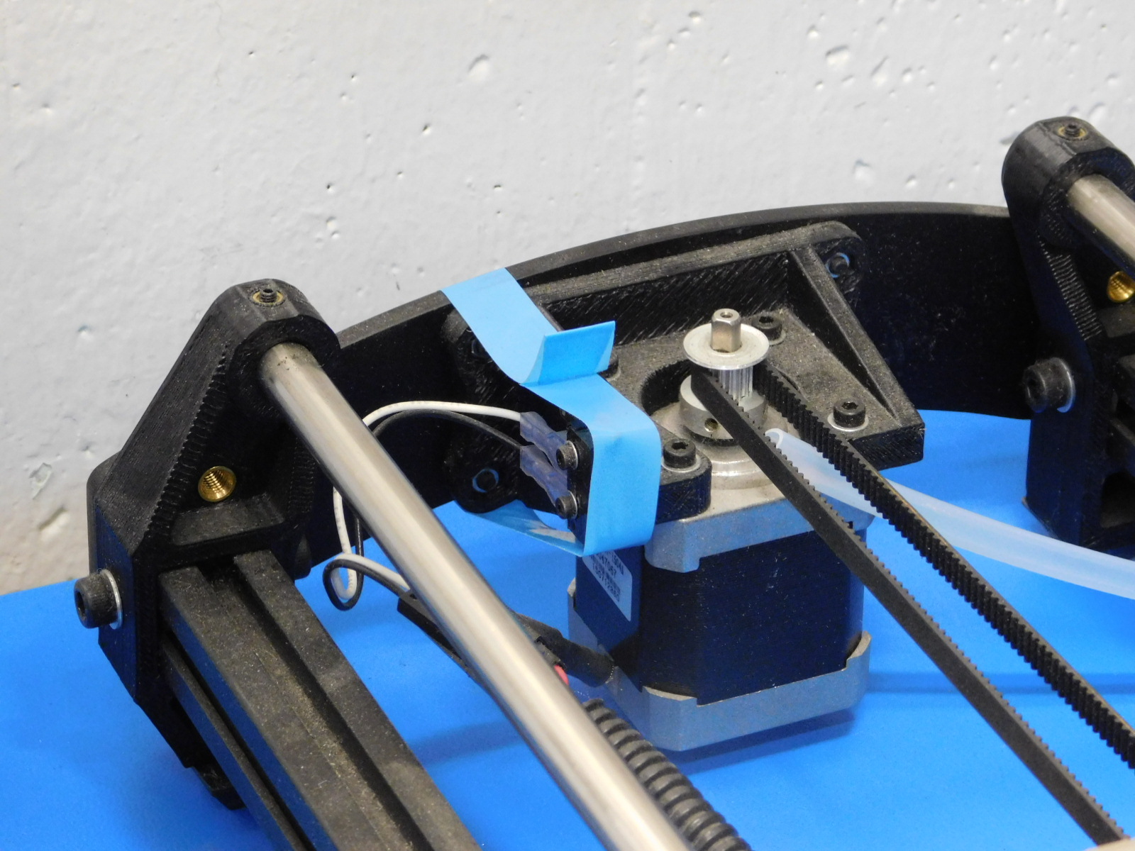
Taping Endstops
To protect your printer from further damage we will have to tape the endstops.
Tape with a small width is best. Packing tape is not advised
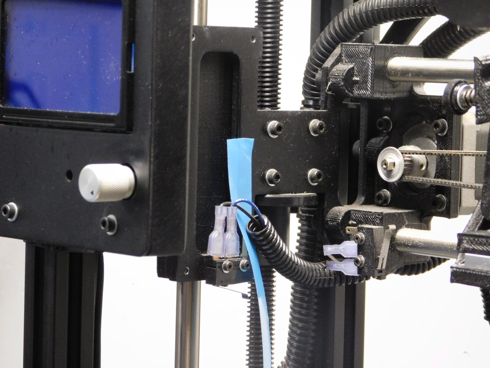
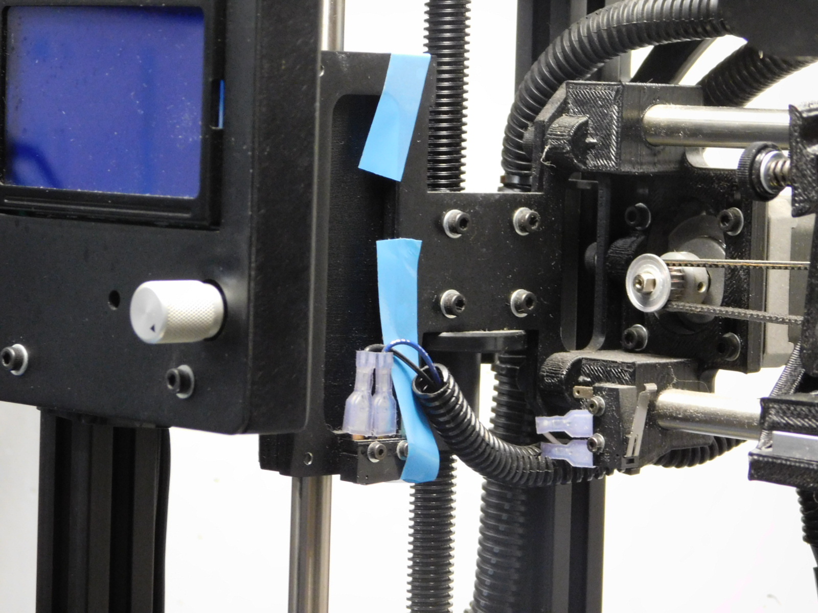
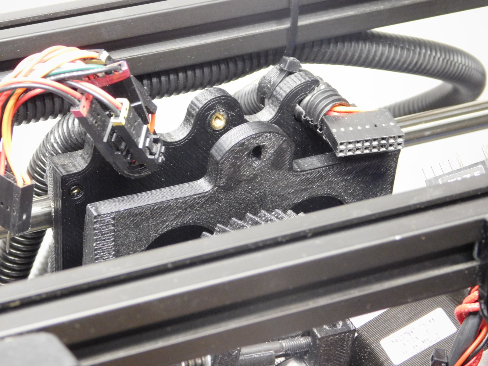
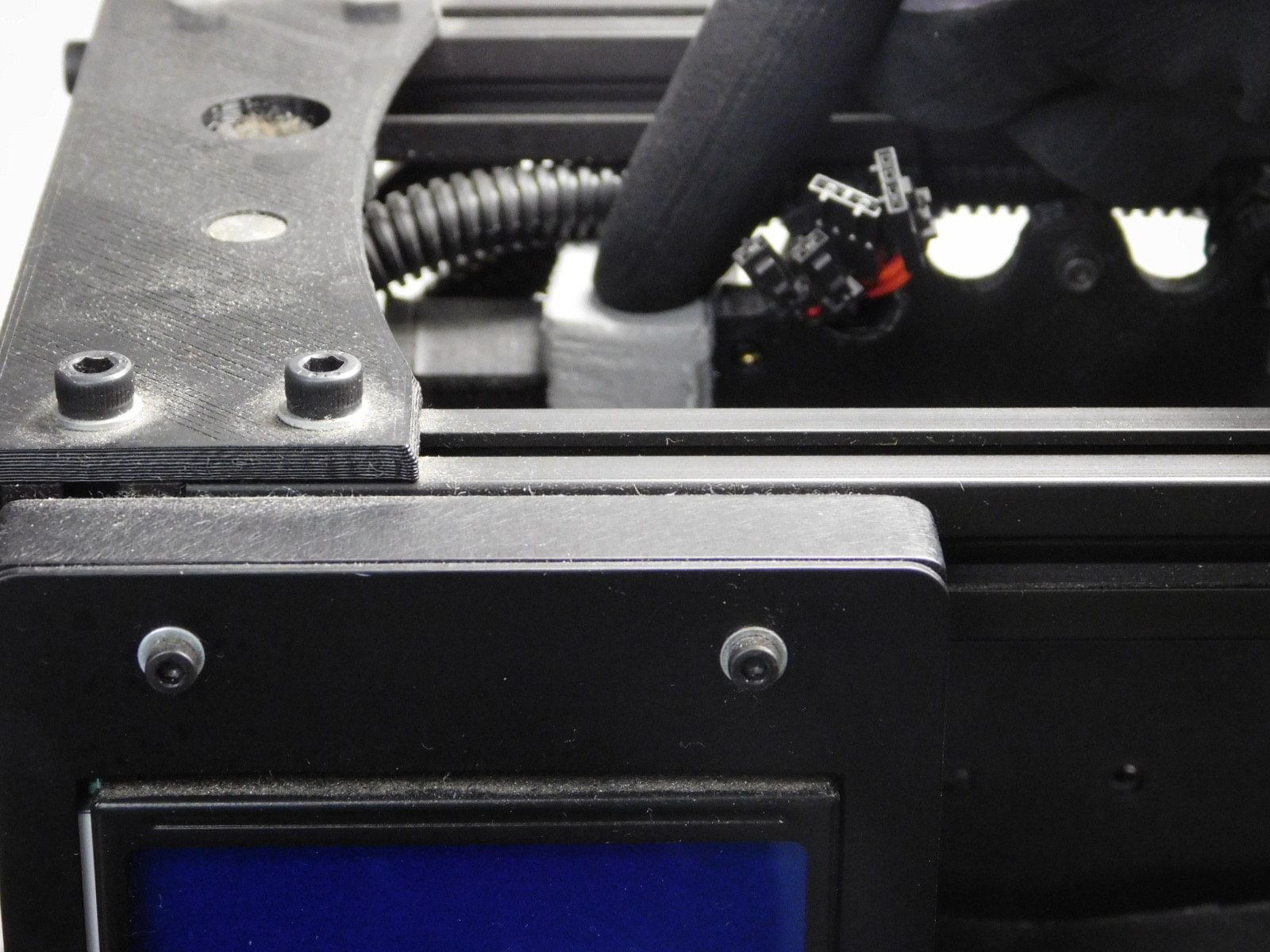
For the Z-min endstop. Tape the internal side of the X-motor mount, tape down, and around the double bearing holder. Be sure the endstop is snug and secure.
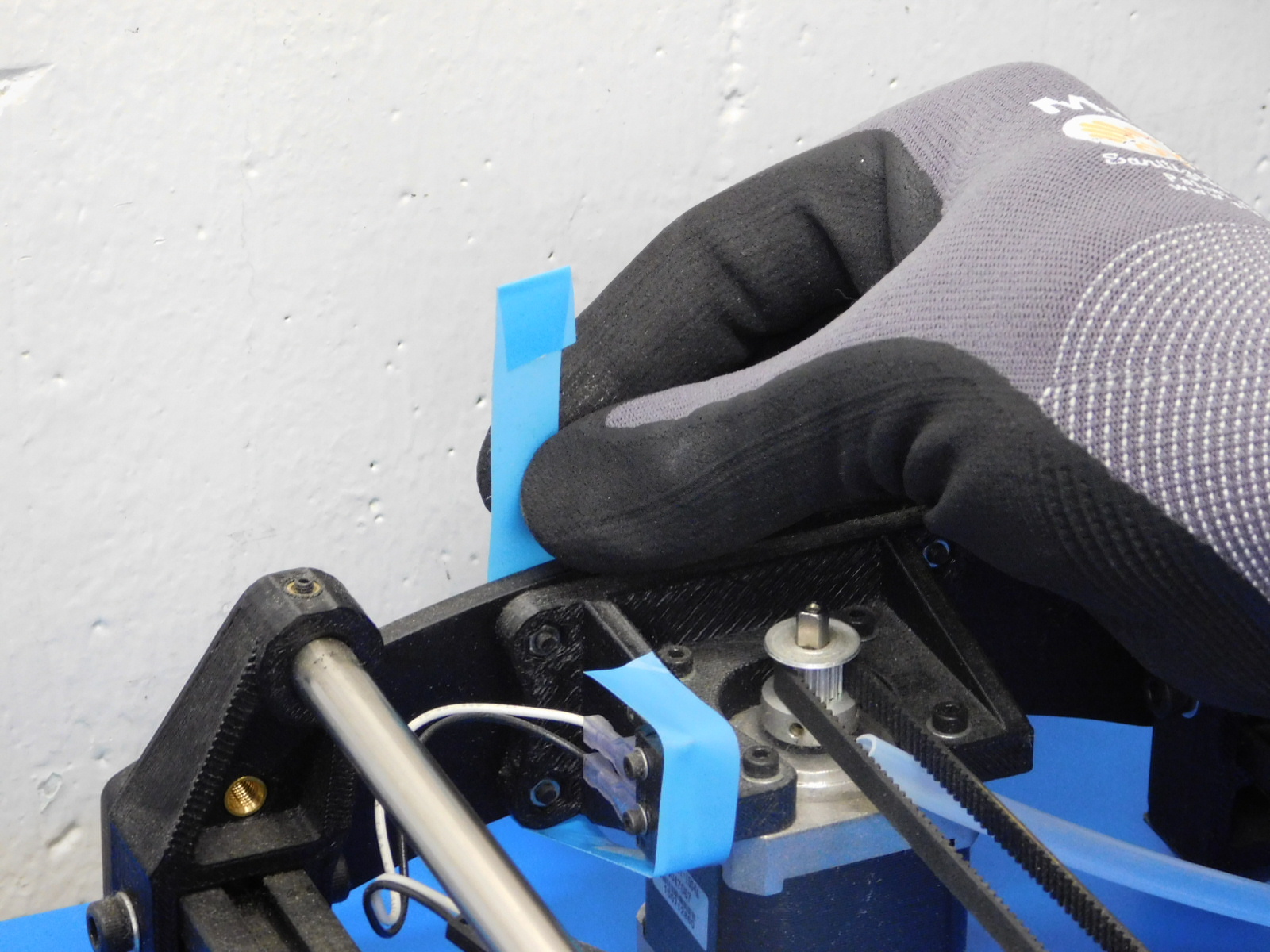
Tape the Y-min the endstop by starting with the tape on top of the y-motor mount, tape down, and around the y-motor mount. Leave a pull tab, if able.
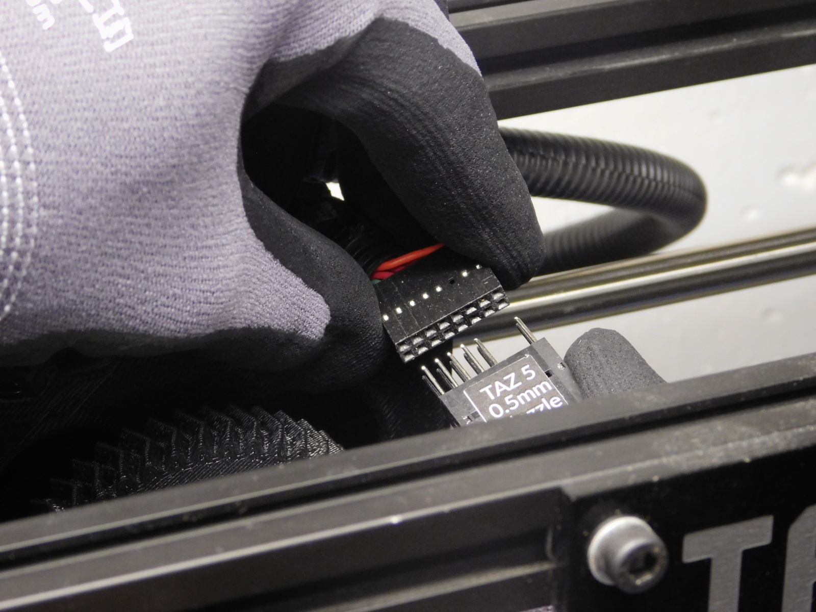
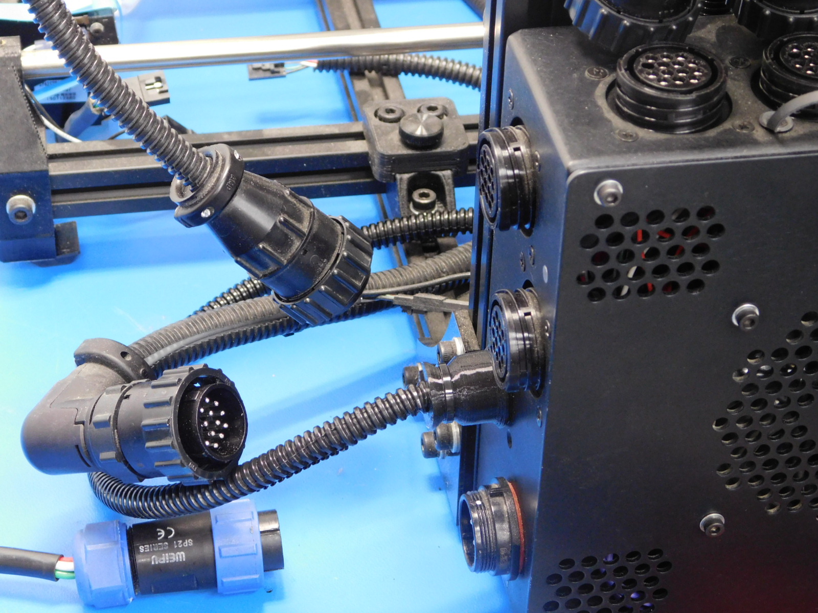
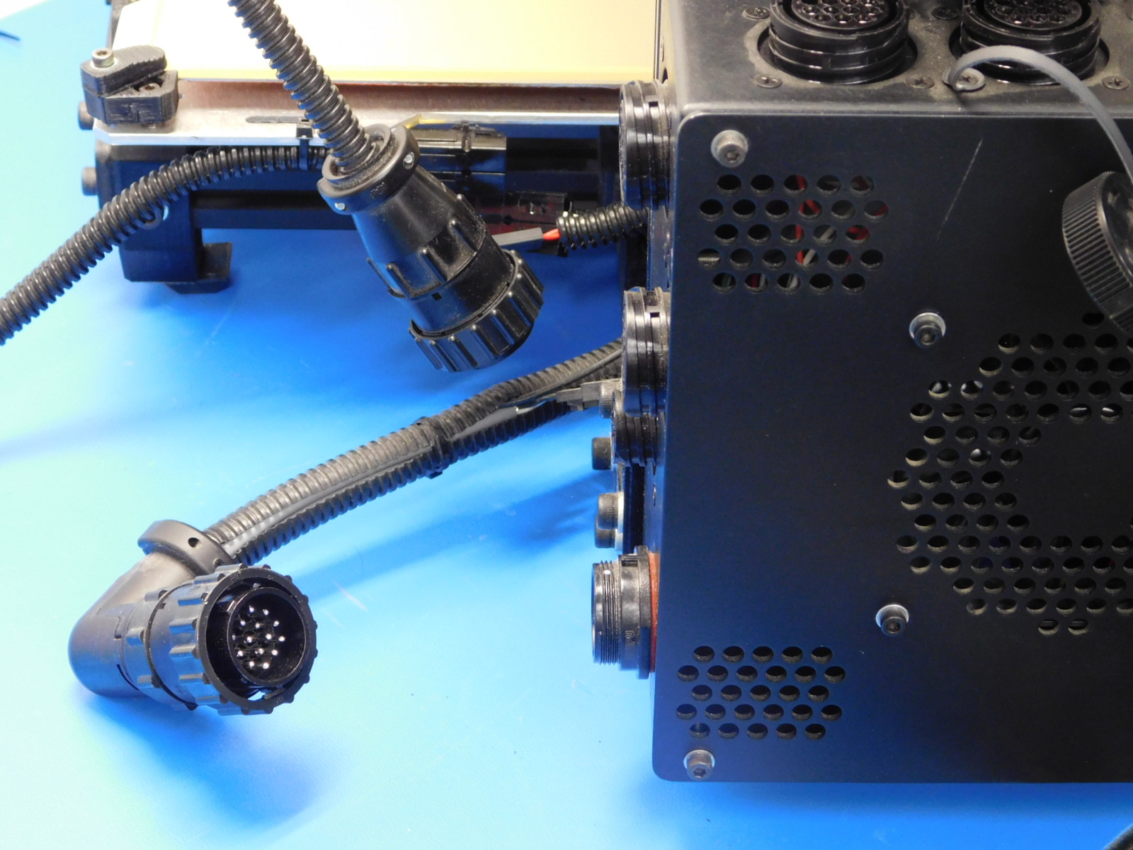
Unplug the following connectors.
1) Unplug the tool head connector. Do not remove tool head yet.
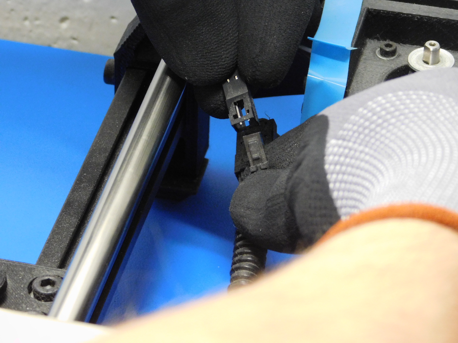
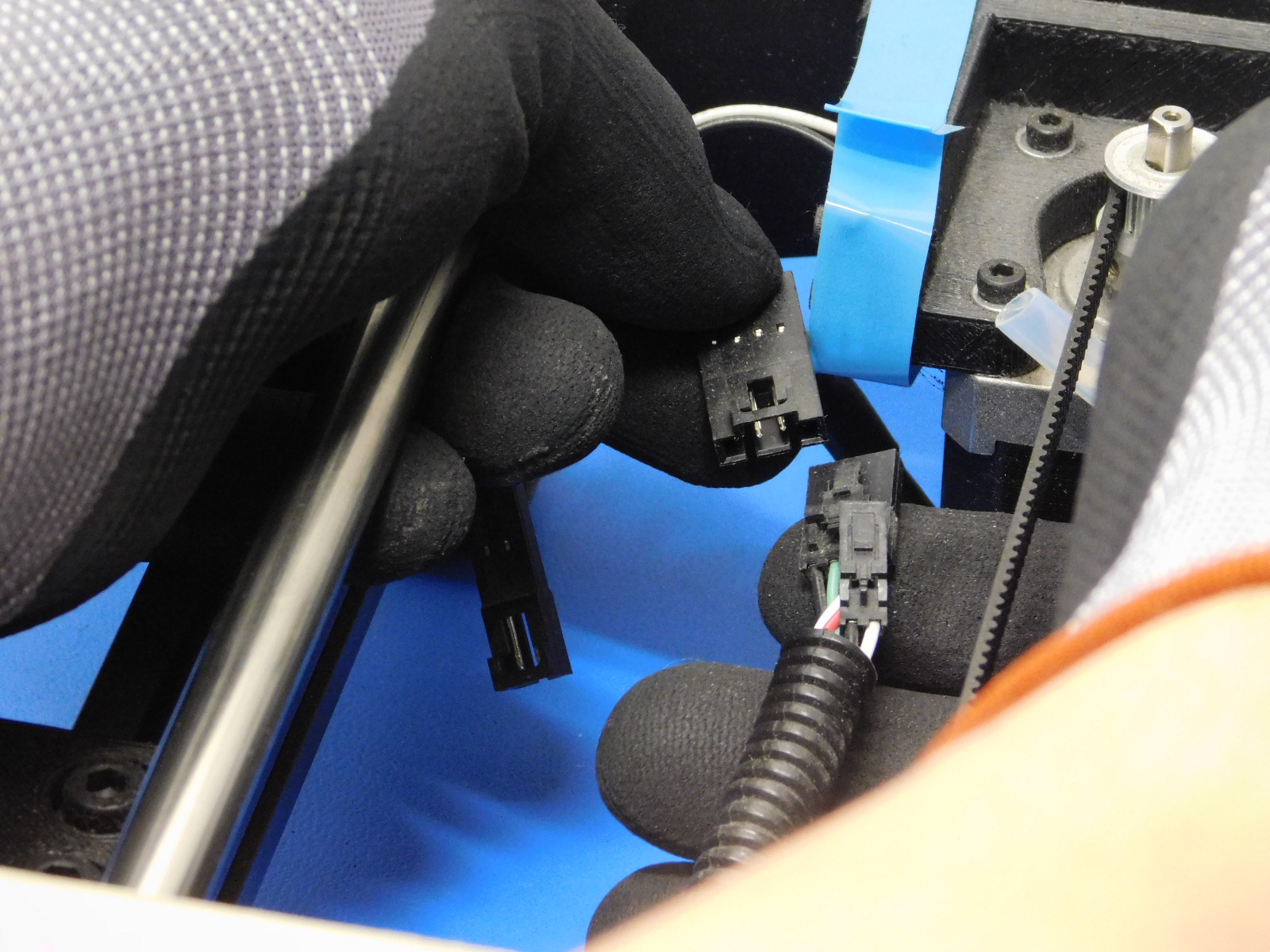
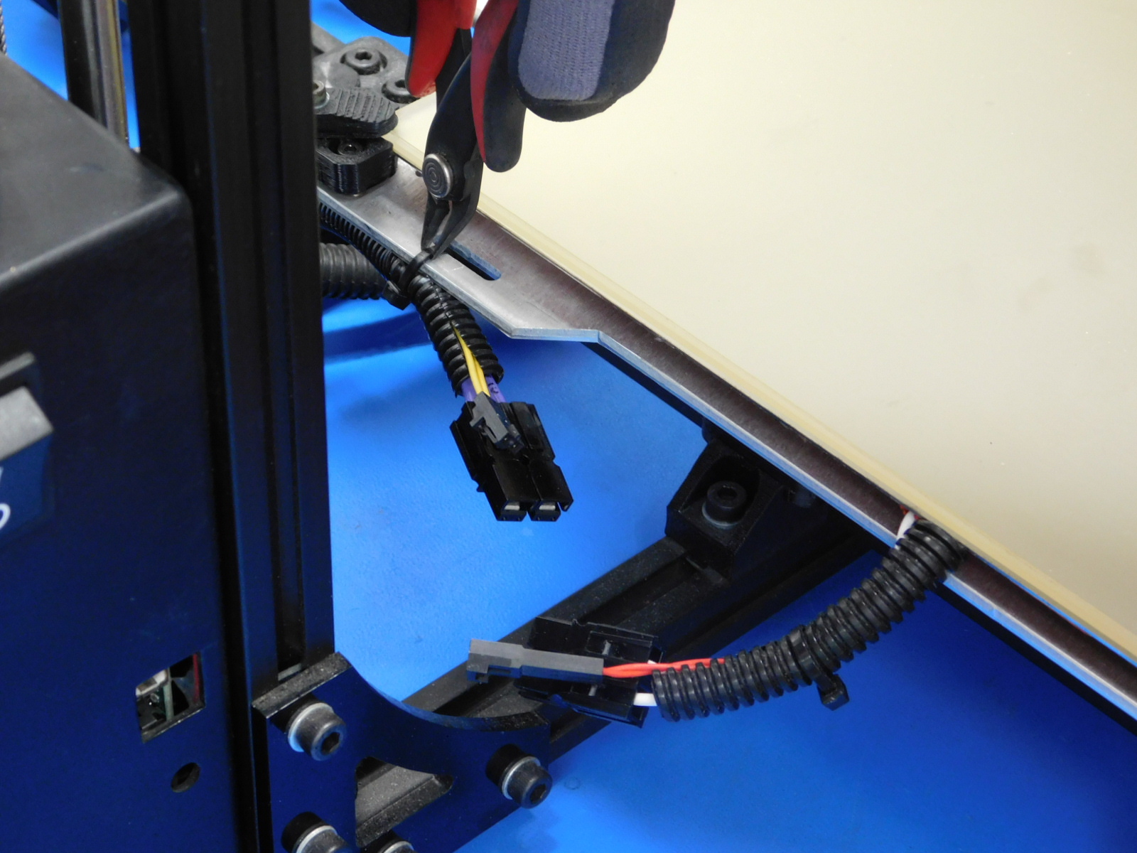
2) Unplug the Y-bed thermistor then the Y-motor
3 A) Option "A" is for customers who have upgrade their bed harness. detach all wires except the bed harness and cut the zip tie at the bed (see photos)
3 B) Option "B" is for customers with the standard bed harness. unplug every connector from the control box and do not cut the zip tie on the bed.
4) Do not unplug the top connectors.
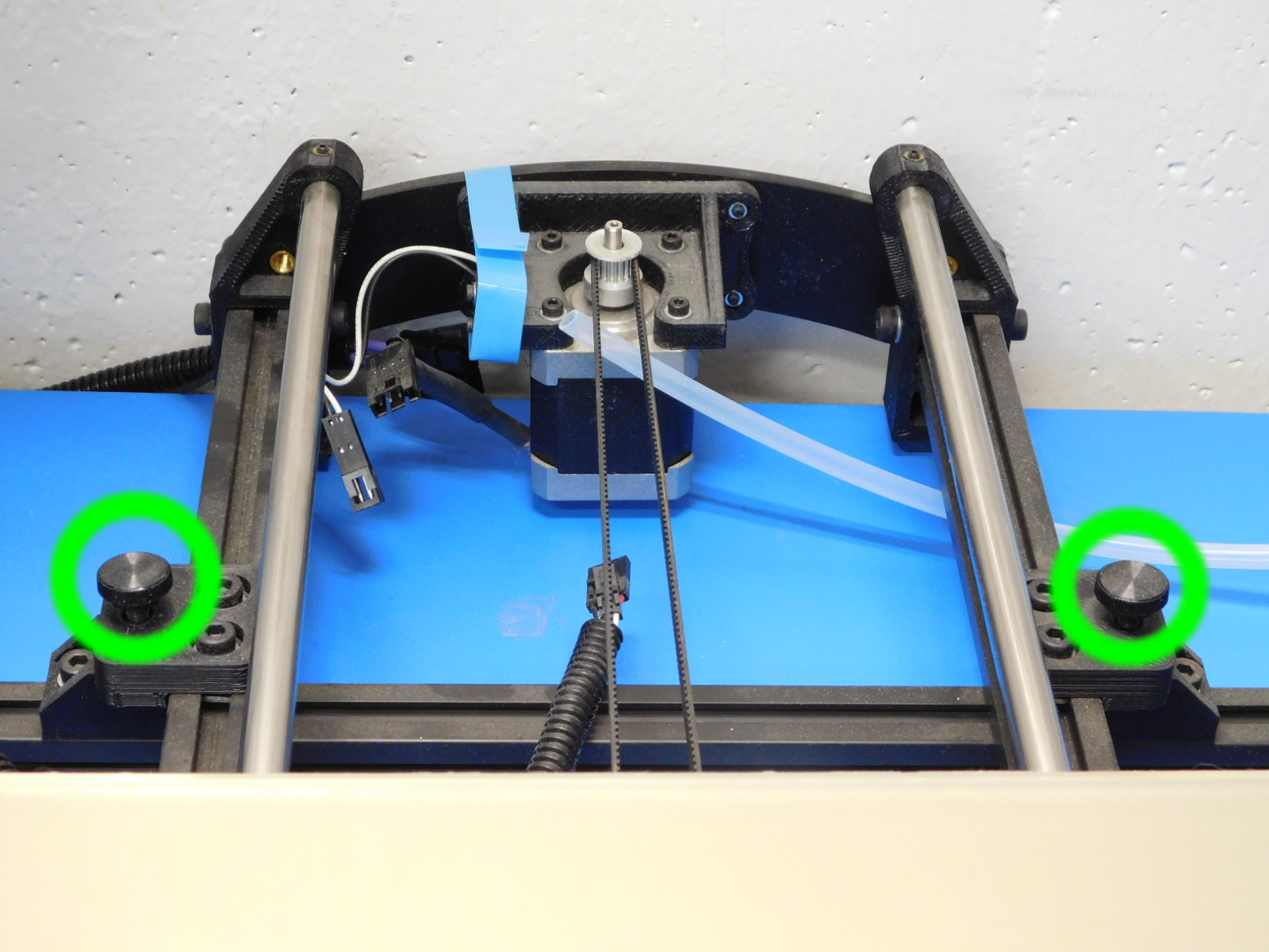
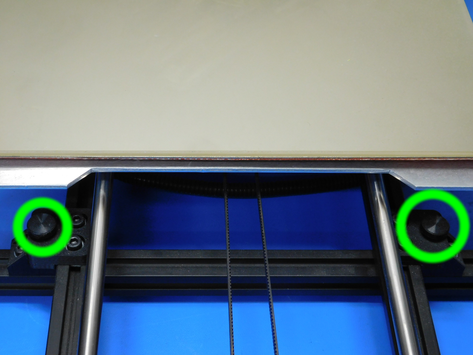
Next, remove the the thumb screws that hold the heat bed in place.
Remove the two front & two back thumb screws as shown.
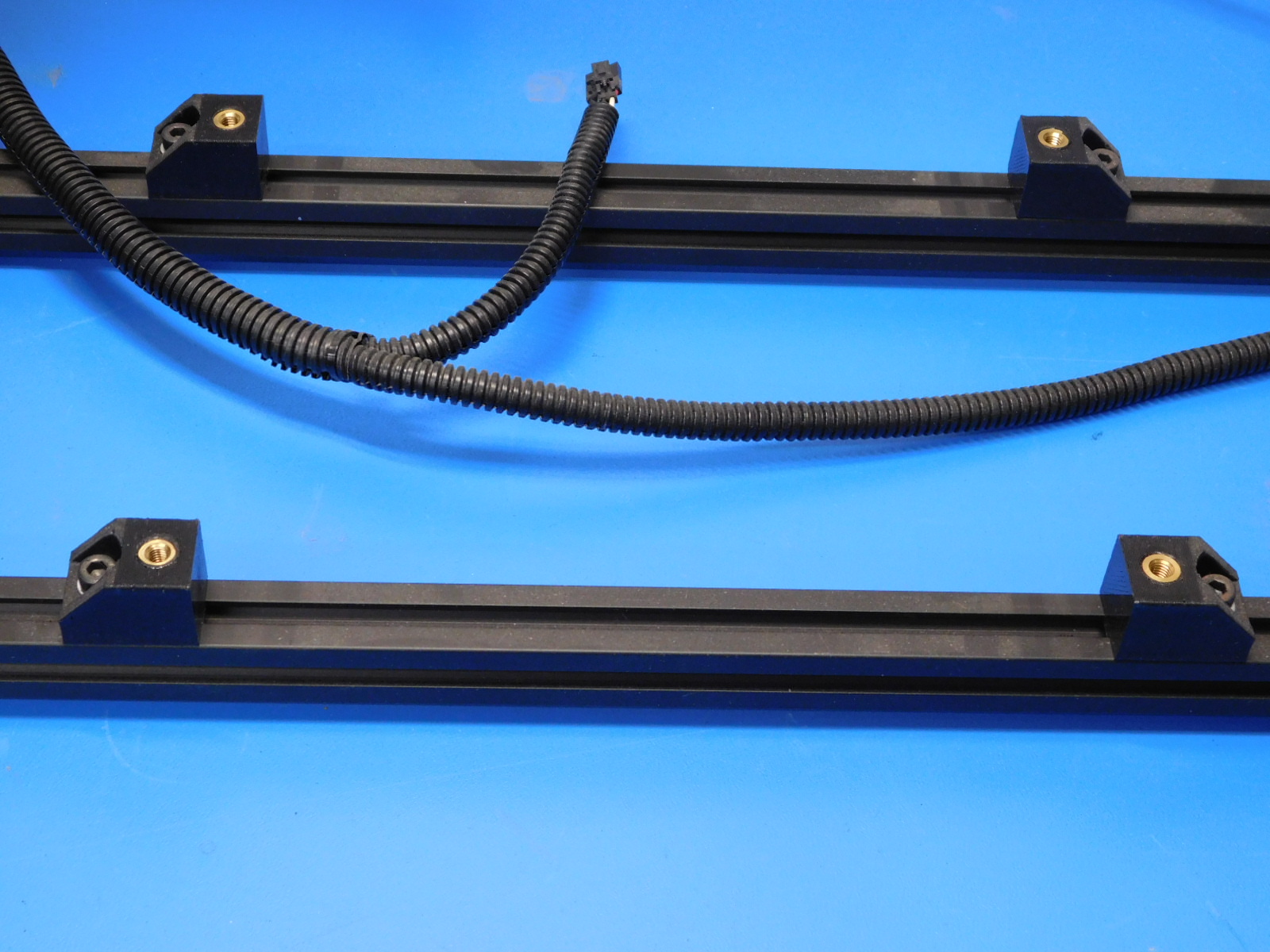
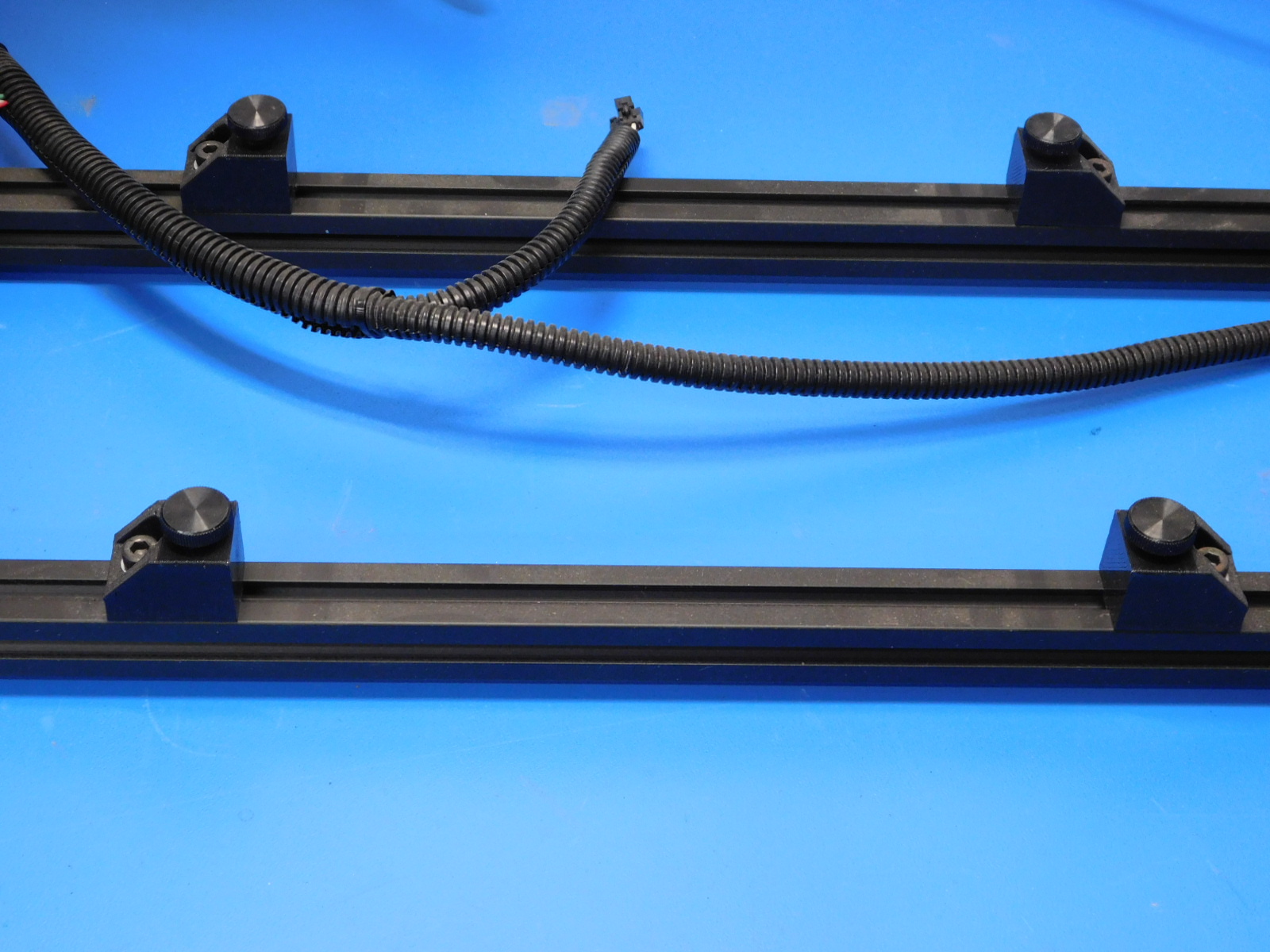
Once bed is removed, return the thumb screws to the printed chassis. (see photos)
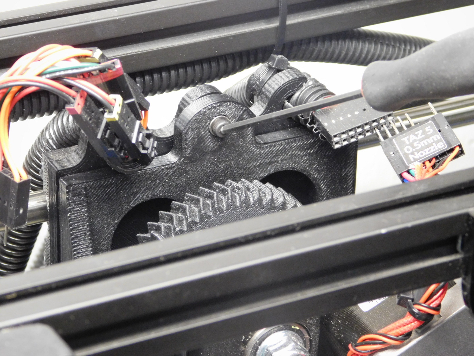
Then remove the M3x12mm screw holding the tool head. Remove and put to the side.
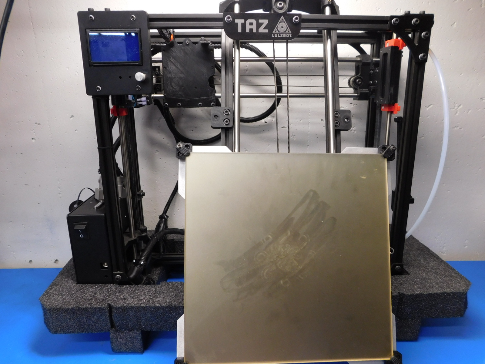
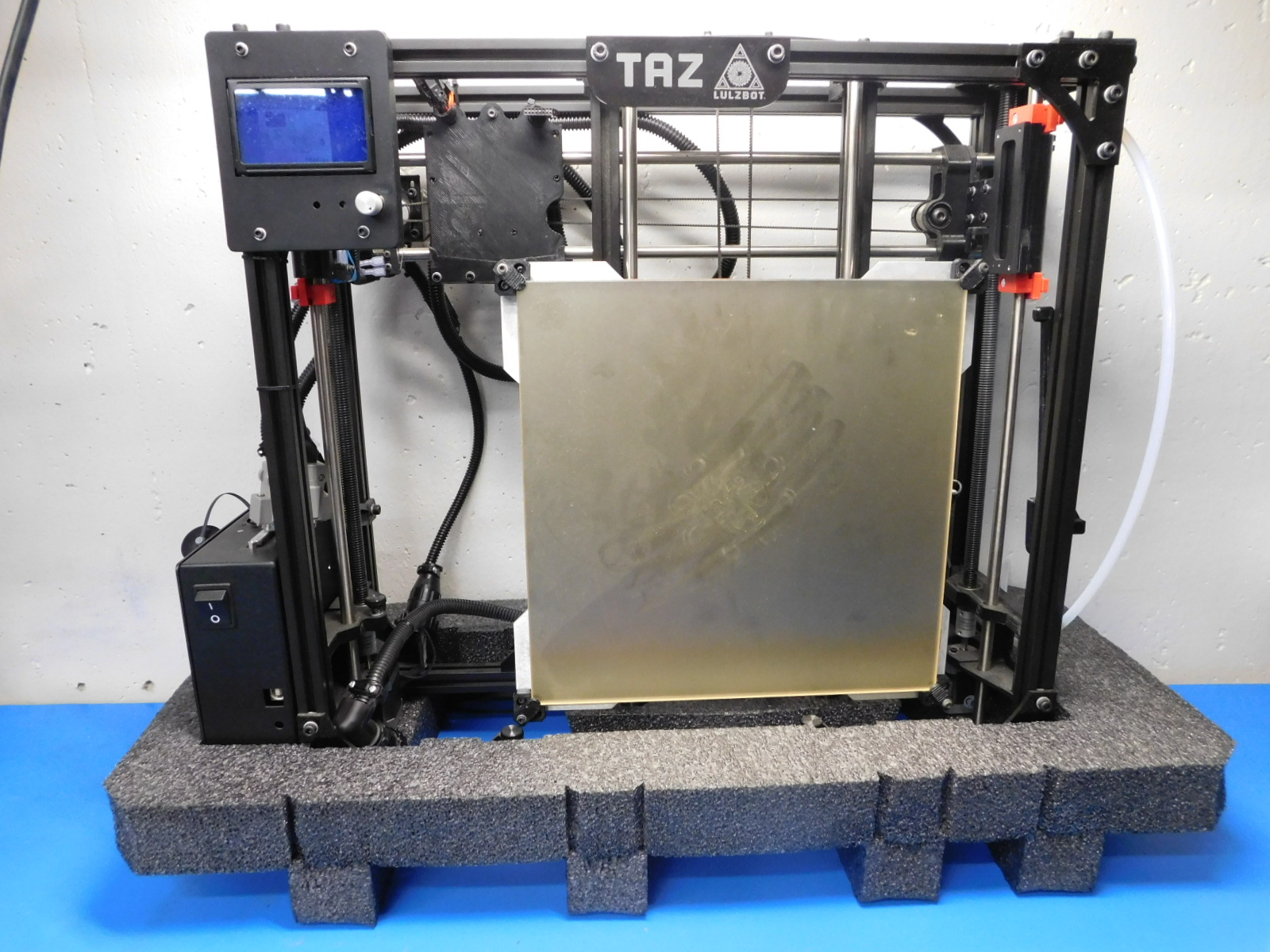
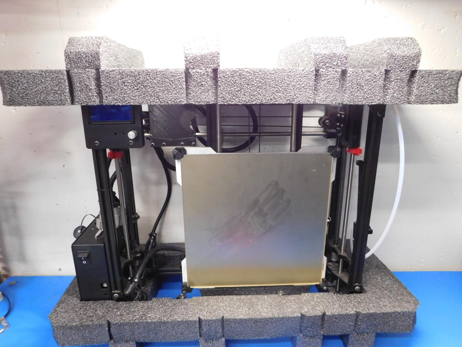
First, place the TAZ in the bottom foam. This can be determined by the cut-out of the for the Y-motor.
Next, slide the X-carriage all the way to the left, be careful not to damage the X-endstop. Then insert the Y-bed to the top of the printer. push up on the Y assembly and place the motor into the cut-out of the bottom foam. (see "Y-bed in place" photo)
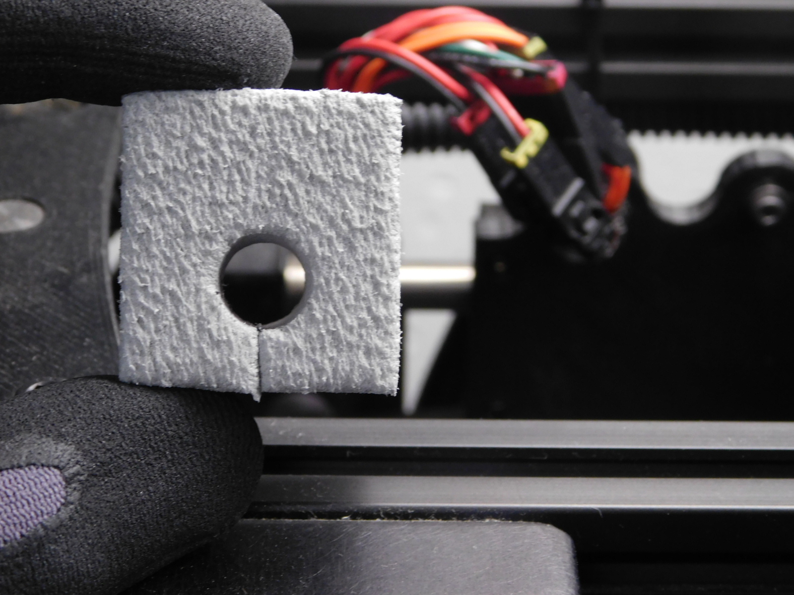
Remove the small gray foam for the x-endstop. This gray foam goes between the x-carriage and the left side of the printer. (see photo)
Place top foam without cutout on the top of the printer.
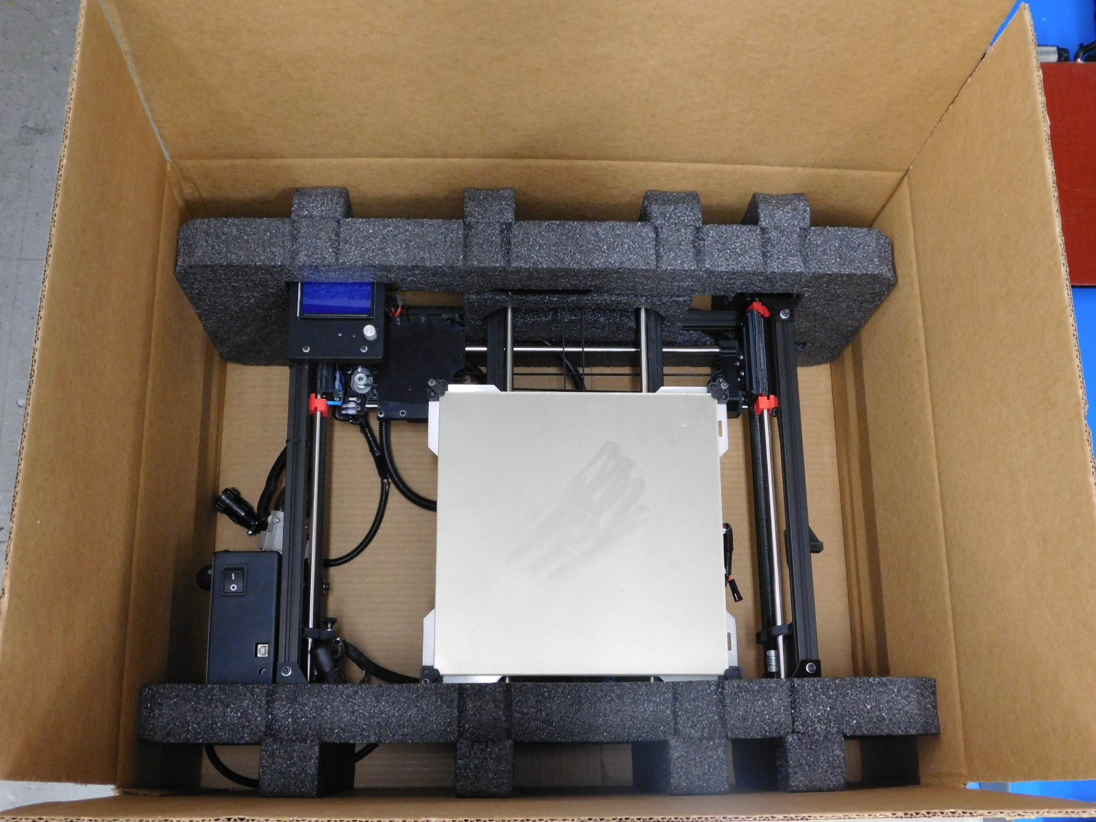
Lay the printer on its back when placing in the provided shipping box.
Add the larger gray foam to the right of the printer. This will hold the spool mount.
Put the accessory foam on top of the printer. Be sure the heat bed is centered to ensure top foam is seated correctly.
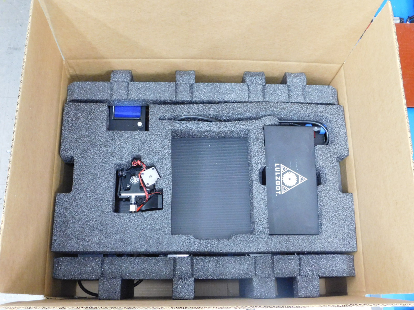
Remove cutouts for the tool head and the power supply.


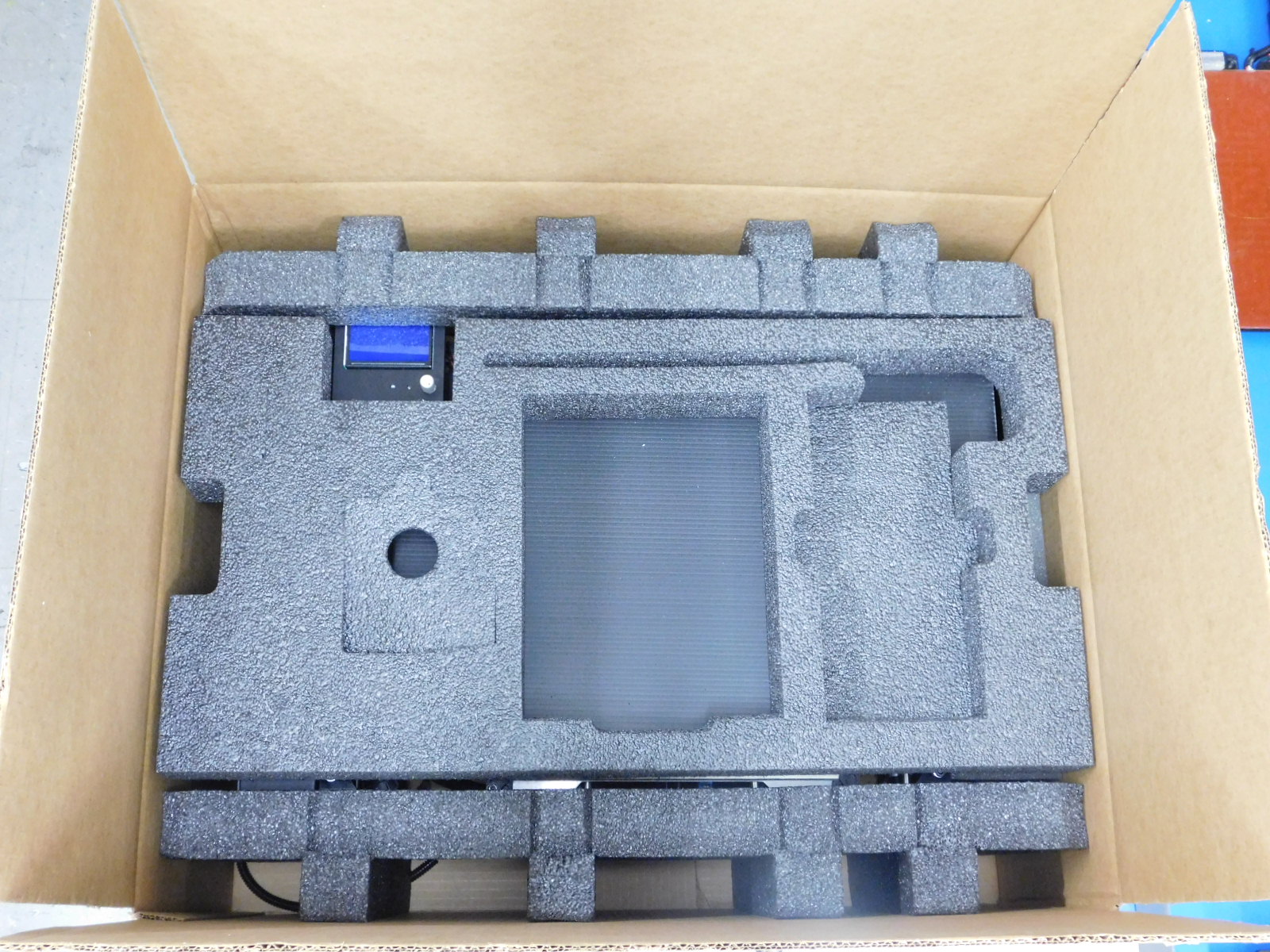
Insert the tool head and the power supply in their designed cutouts. Keep in mind the tool head molex pins can bend and break, this could be damaged while inserting in foam.
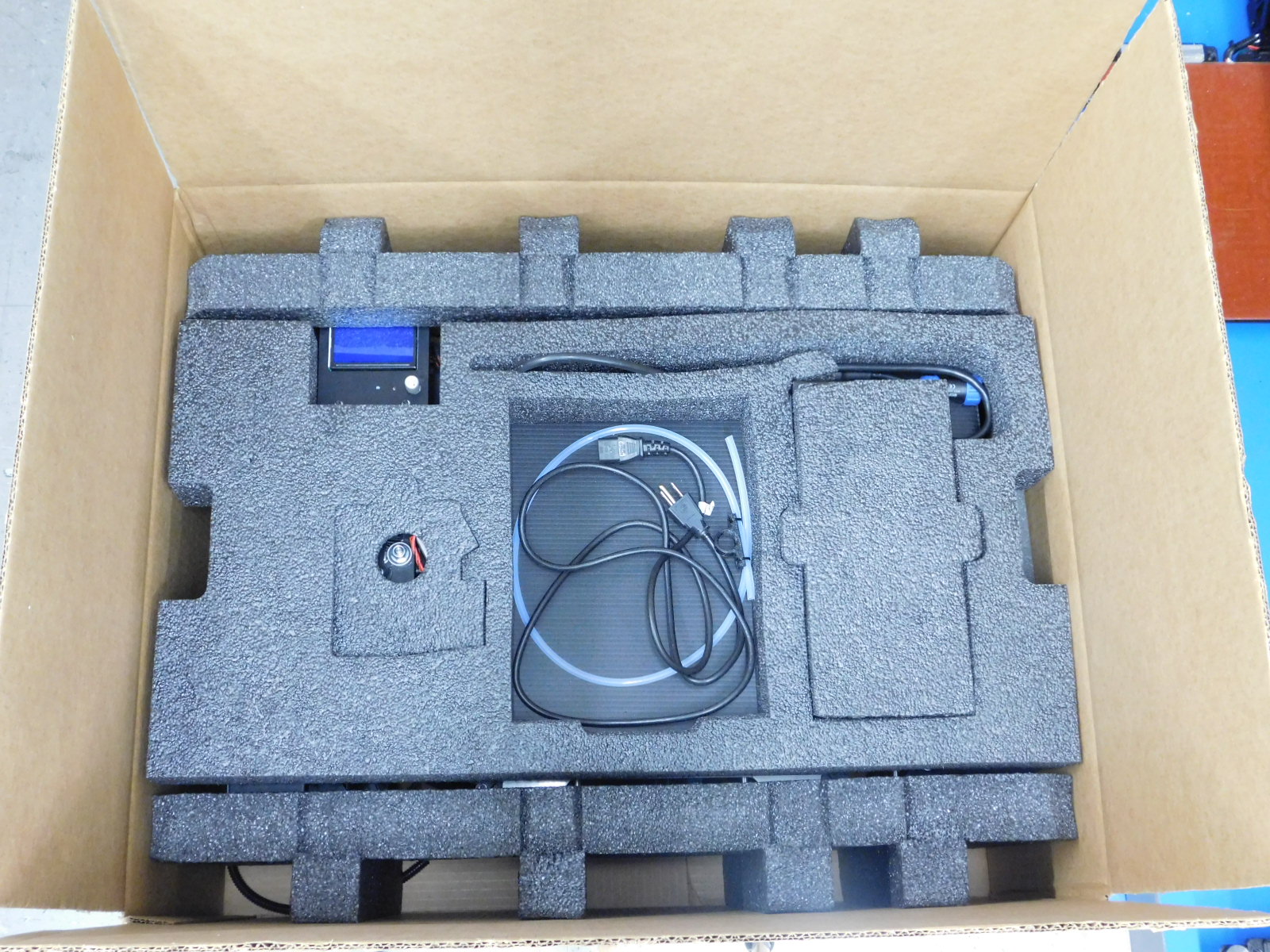
Place any paperwork, prints, power cords, and USB cables in the center foam piece. There is no cutout top for this square.
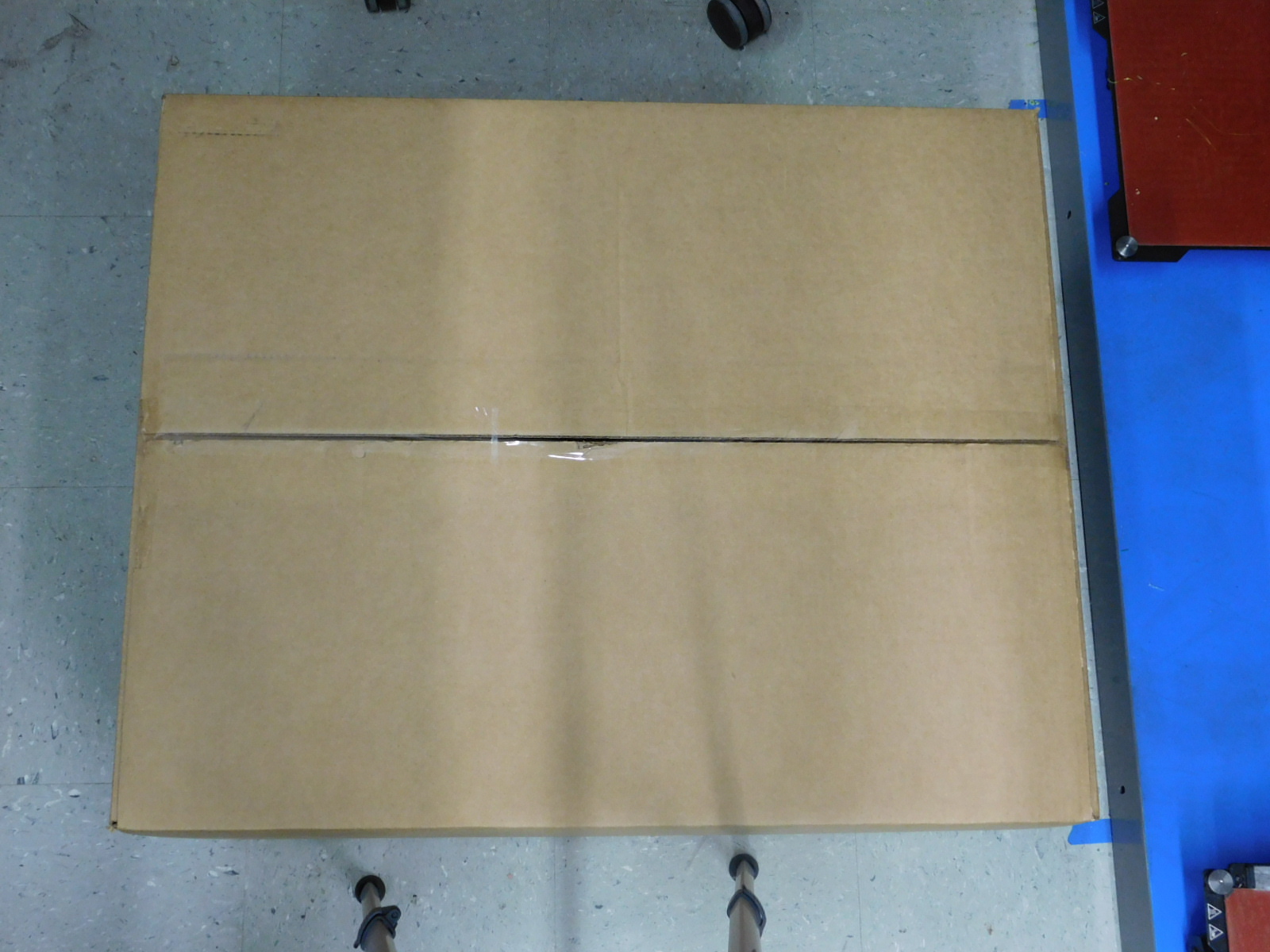
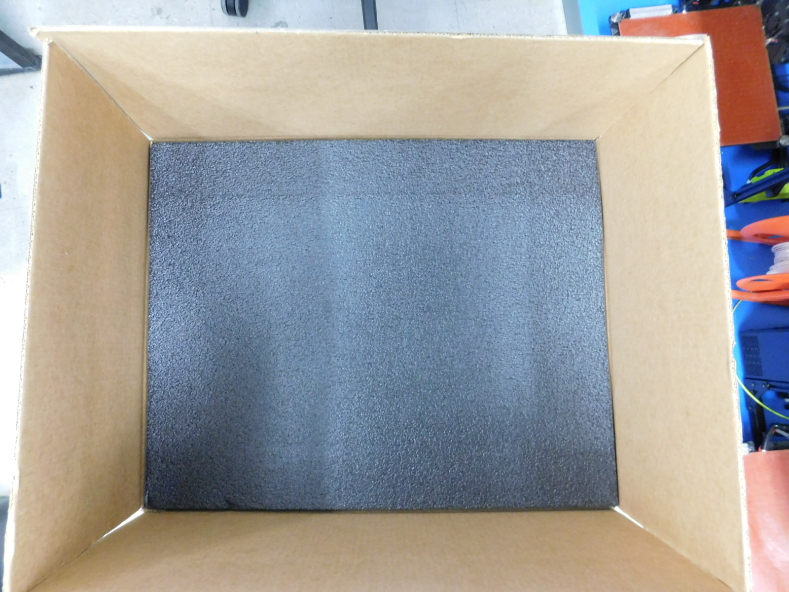
Lastly, place the large flat top foam piece down as shown in photo.
The the box, be sure to write the LRS number on the box if applicable and place the RWB, visibly, on top of the box.