Open HardwareAssembly Instructions
Guides for installation and assembly of the LulzBot line of products made by FAME 3D LLC.
Guides for installation and assembly of the LulzBot line of products made by FAME 3D LLC.
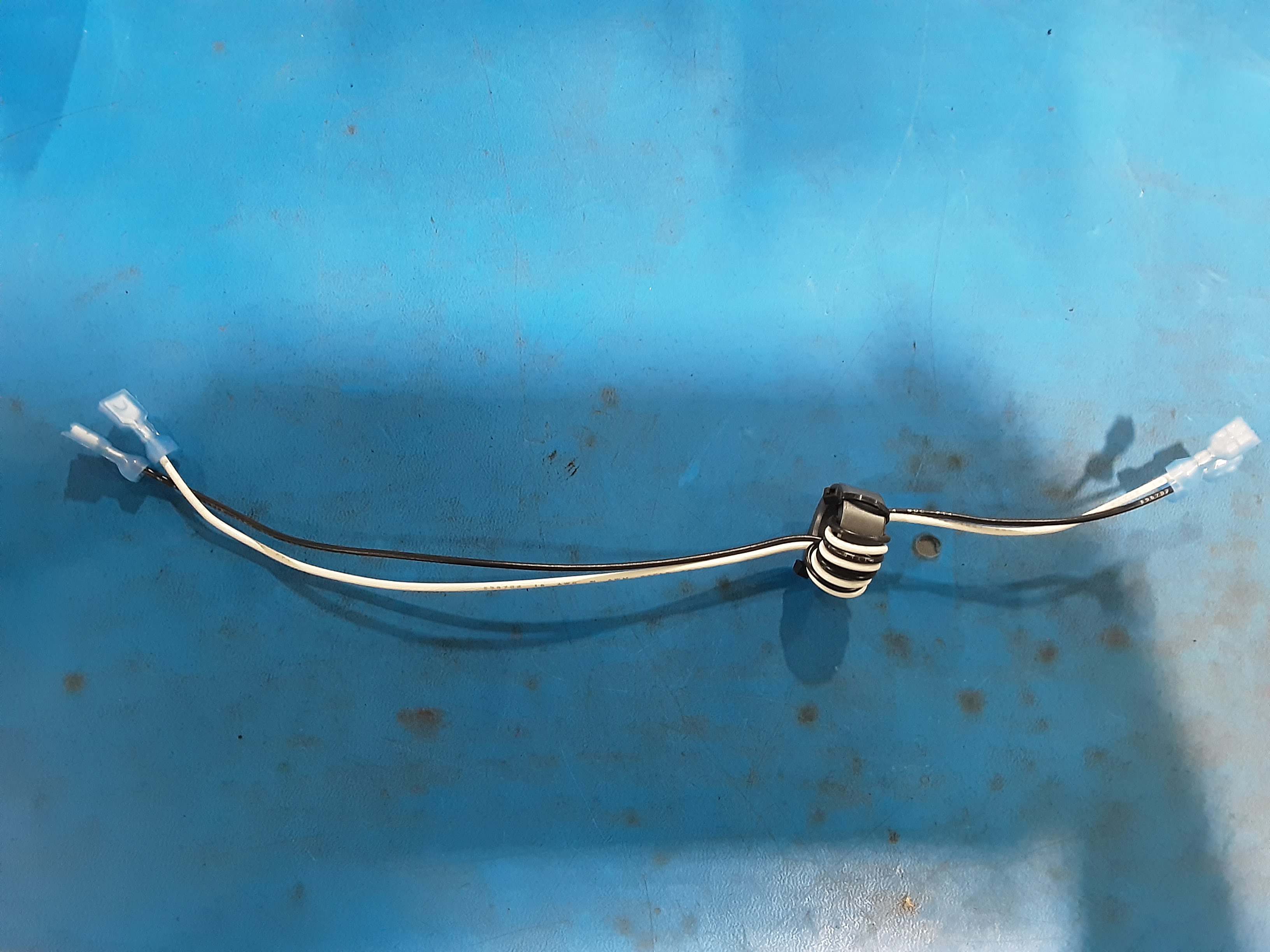
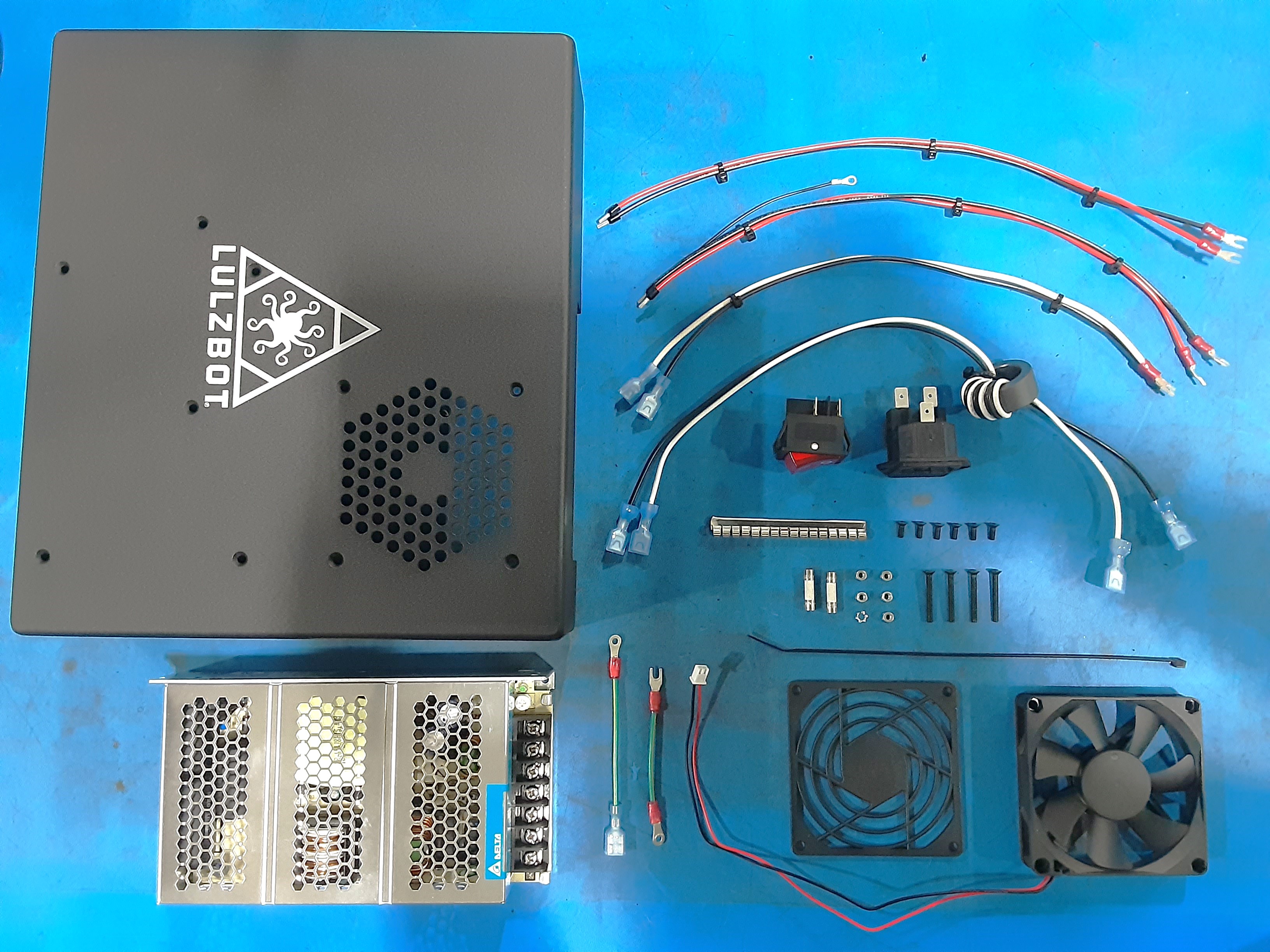
1x [AS-CB0073] Mini 2, Plug to SW Extension Harness Assembly
1x [AS-CB0079] Mini 2, Plug to Ground Post Extension
1x [EL-HR0109] Finger Guard 80mm Plastic
1x [EL-HR0216] Mini3, PS to Board Main Power
1x [EL-HR0217] Mini3, PS to Board Bed Power
1x [EL-HR0225] SW to PSU
1x [EL-HR0226] PSU to Ground
1x [EL-HR0227] Case Fan, Mini3
2x [EL-MS0414] Cartridge Fuse 250V 3.15A Slo-Blo
1x [EL-MS0432] Clip-On EMI Shielding Gasket 150.876mm length
1x [EL-PS0025] DELTA POWER SUPPLY 150W 24V 6.25A PNL MT
1x [EL-SW0023] SWITCH ROCKER DPST 20A 250V, Illuminated Red
6x [HD-BT0130] M3 x 8 Bolt, FHCS Black-Oxide
4x [HD-BT0206] Black-Oxide Alloy Steel Hex Drive FHCS M3 x 25mm Long
1x [HD-MS0058] Wire Tie, 8" Black, pk 1000
5x [HD-NT0001] Metric Zinc-Plated Steel Nylon-Insert Locknut, M3 Size
1x [HD-WA0035] Metric 18-8 Stainless Steel External Serrated Lock Washer, M3 Size
1x [PP-FP0242] Mini3, Electronics-Case, 12AWG Aluminum, Rev 0-5
1x [PP-MP0028] Bulgin-AC Power Entry Modules SC MT FUSED .25" TAB
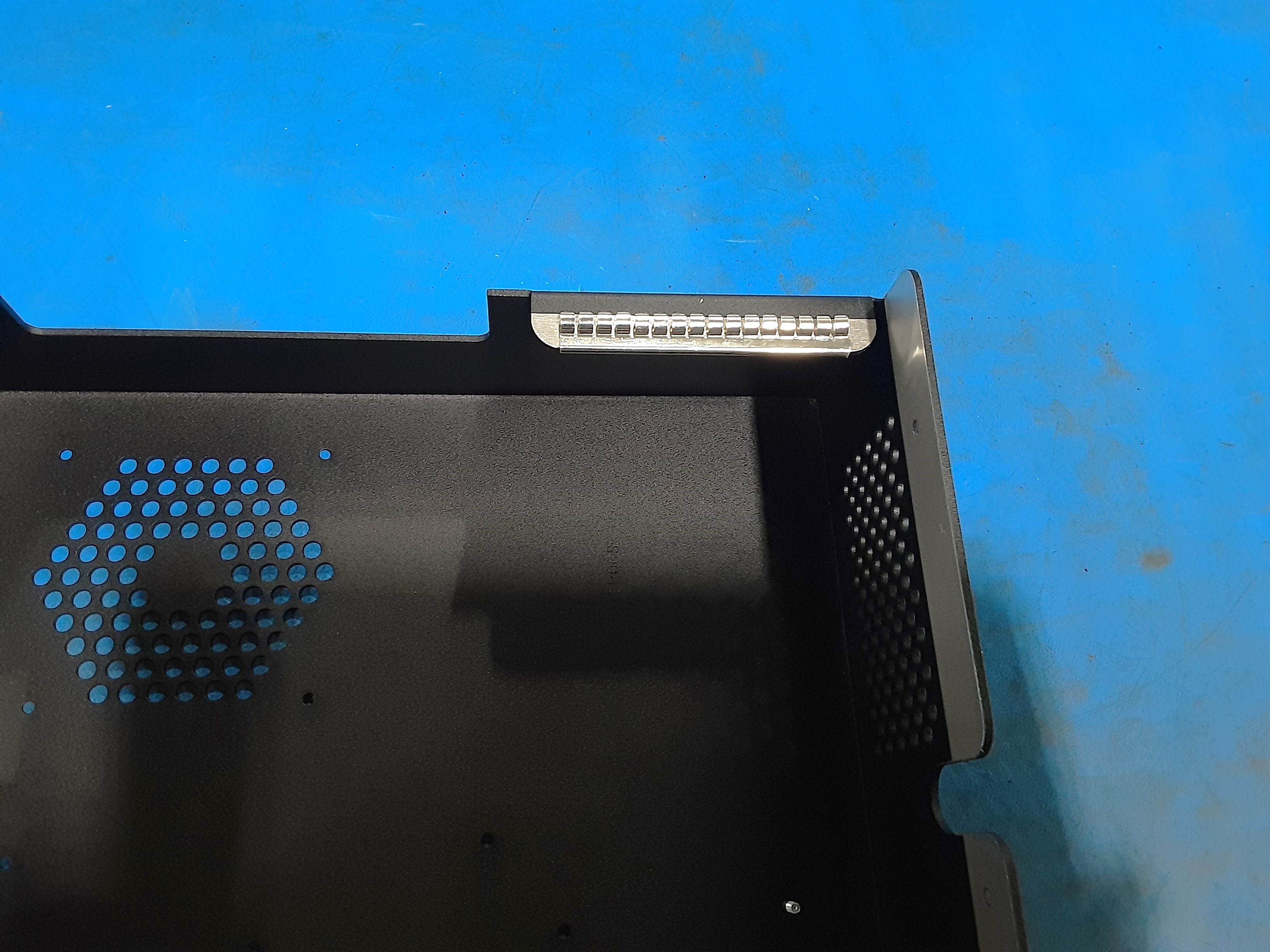
Switches and Fan
2A) Grab PP-FP0242 and attach EL-MS0432 where shown.
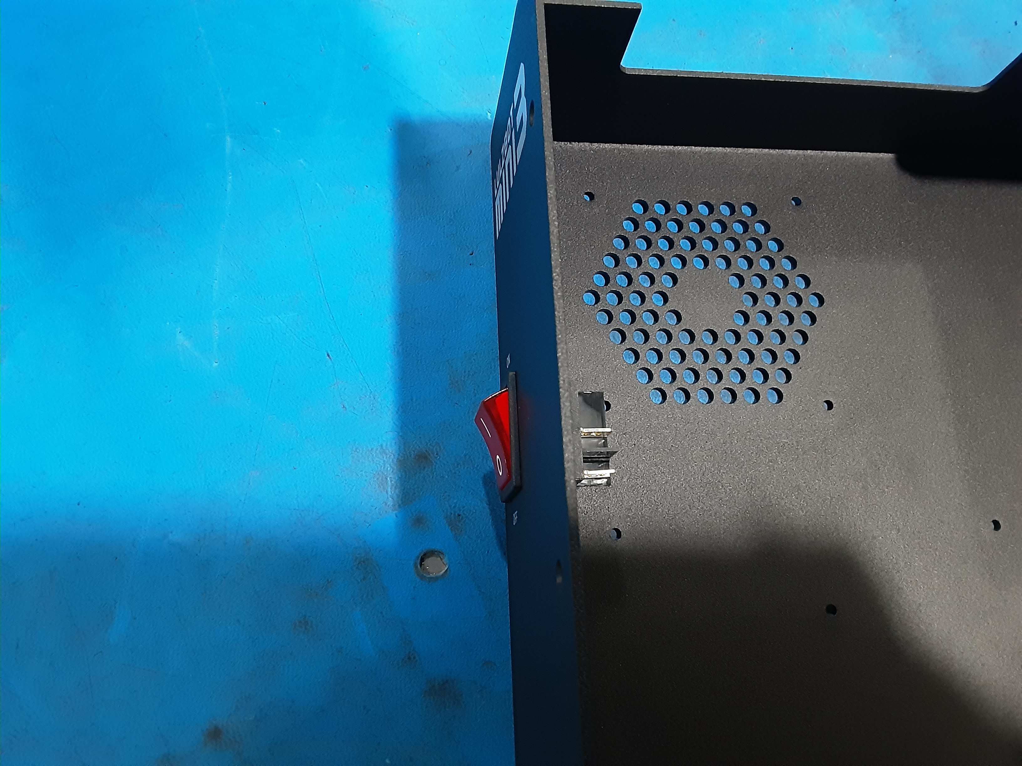
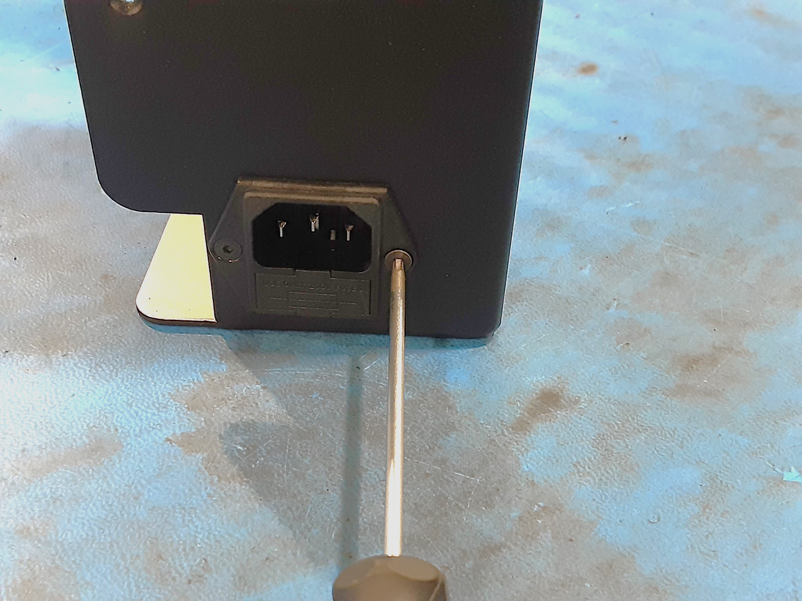
2B) Install EL-SW0023 into PP-FP0242 in shown orientation.
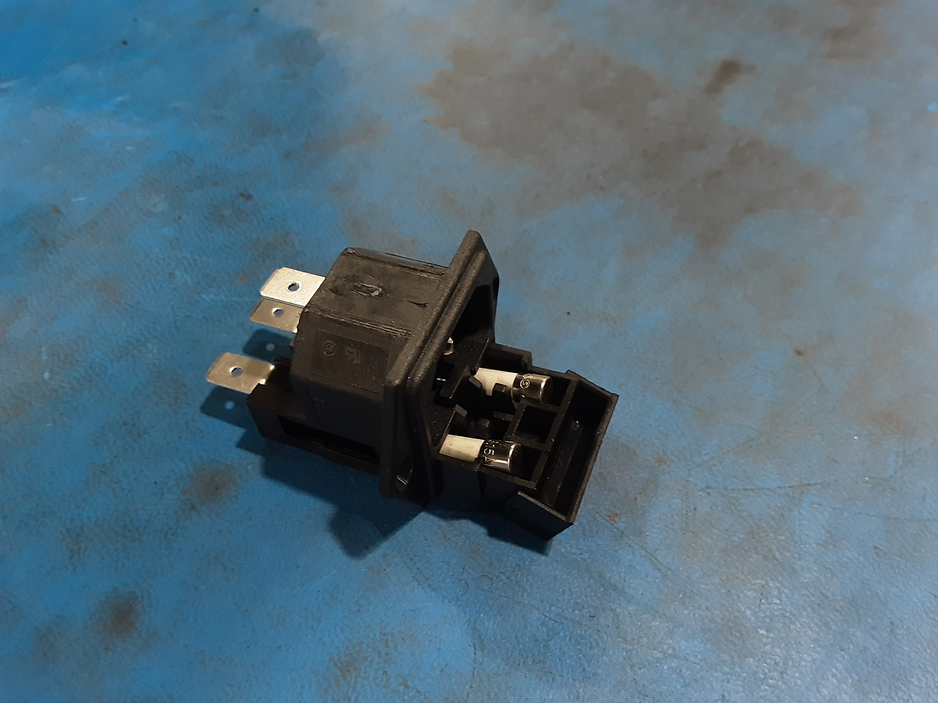
2C) Open up the fuse housing in PP-MP0028 and install EL-MS0414 x2.
2D) Attach PP-MP0028 to PP-FP0242 using HD-BT0130 x2.
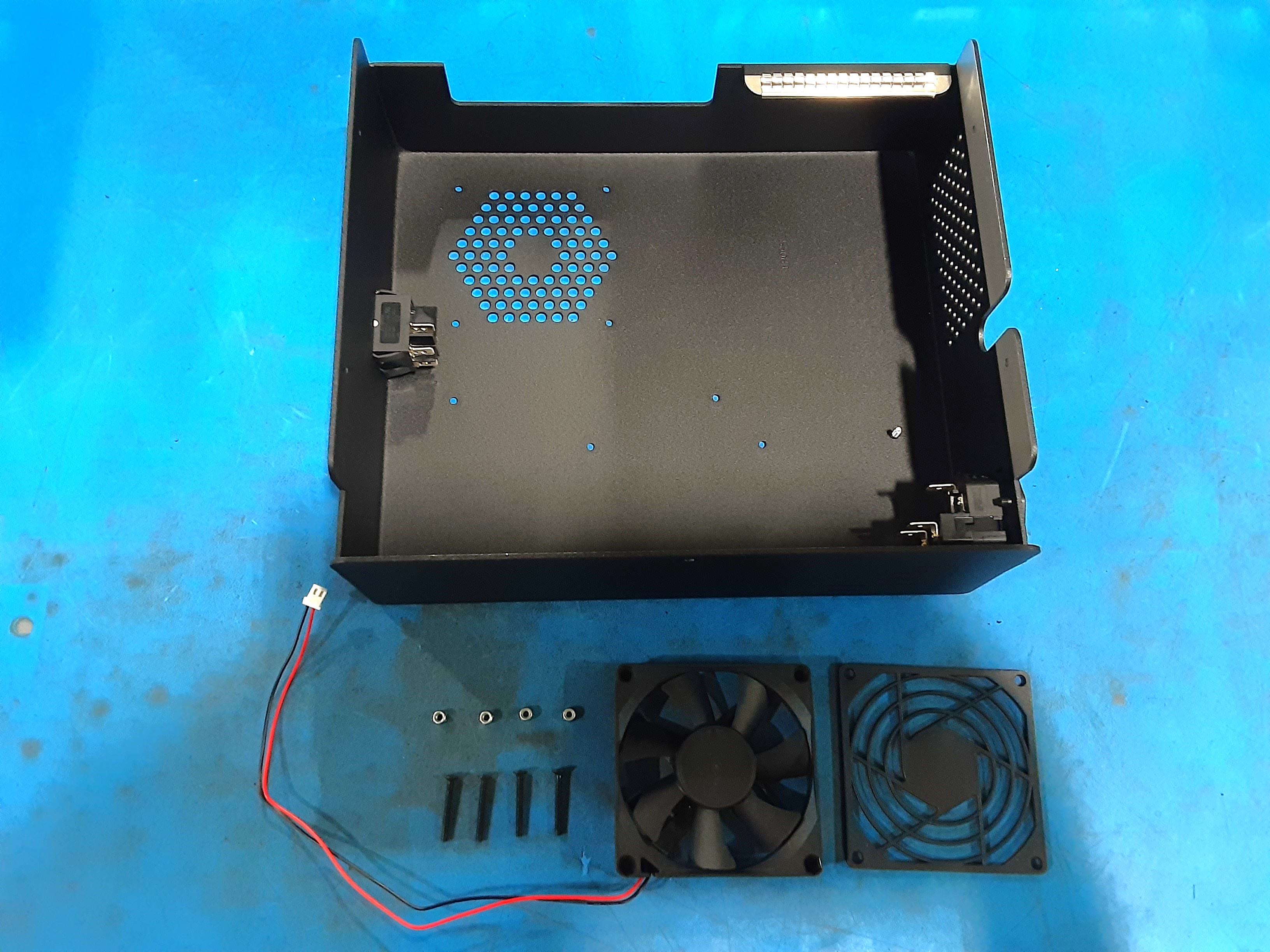
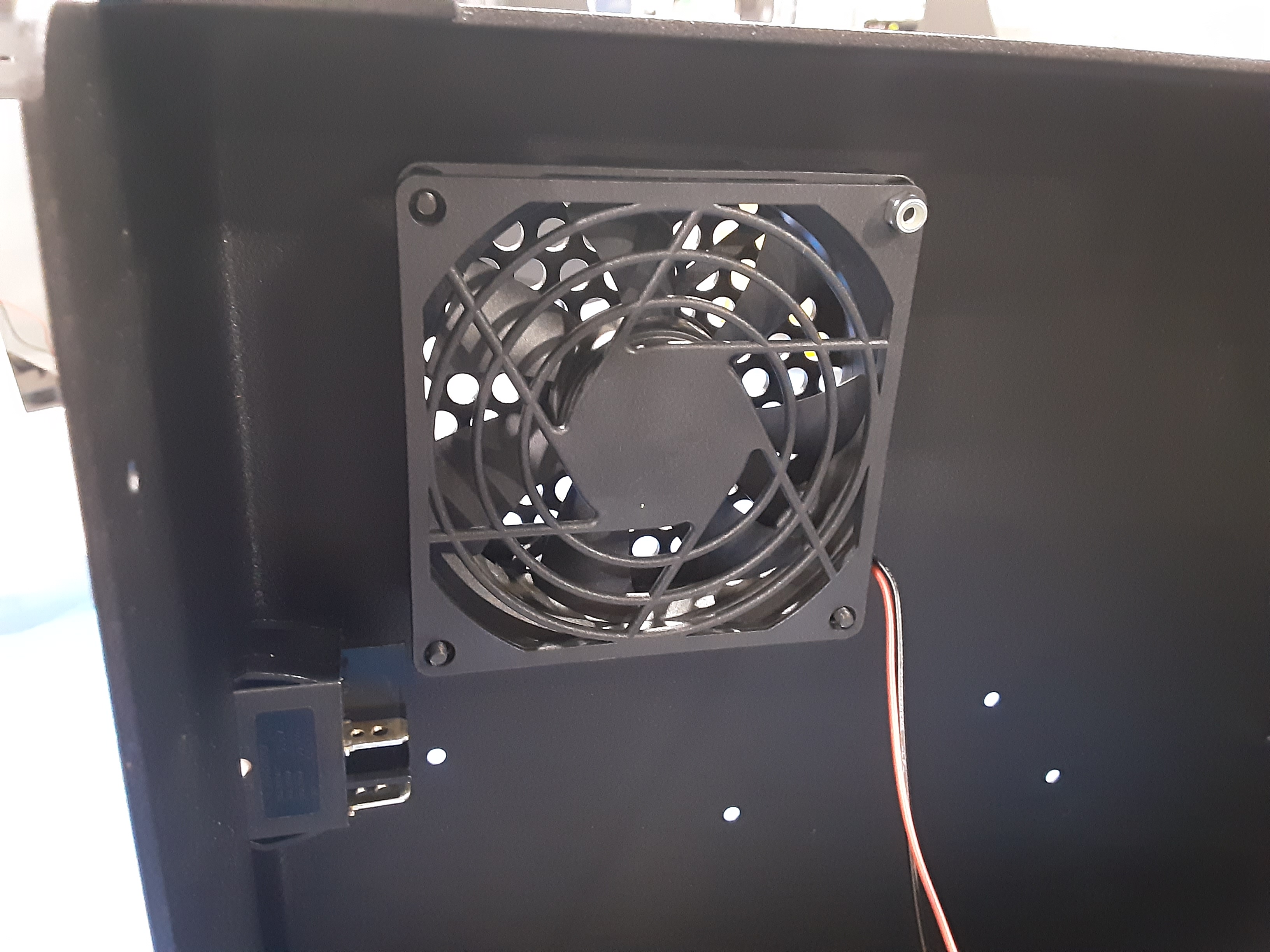
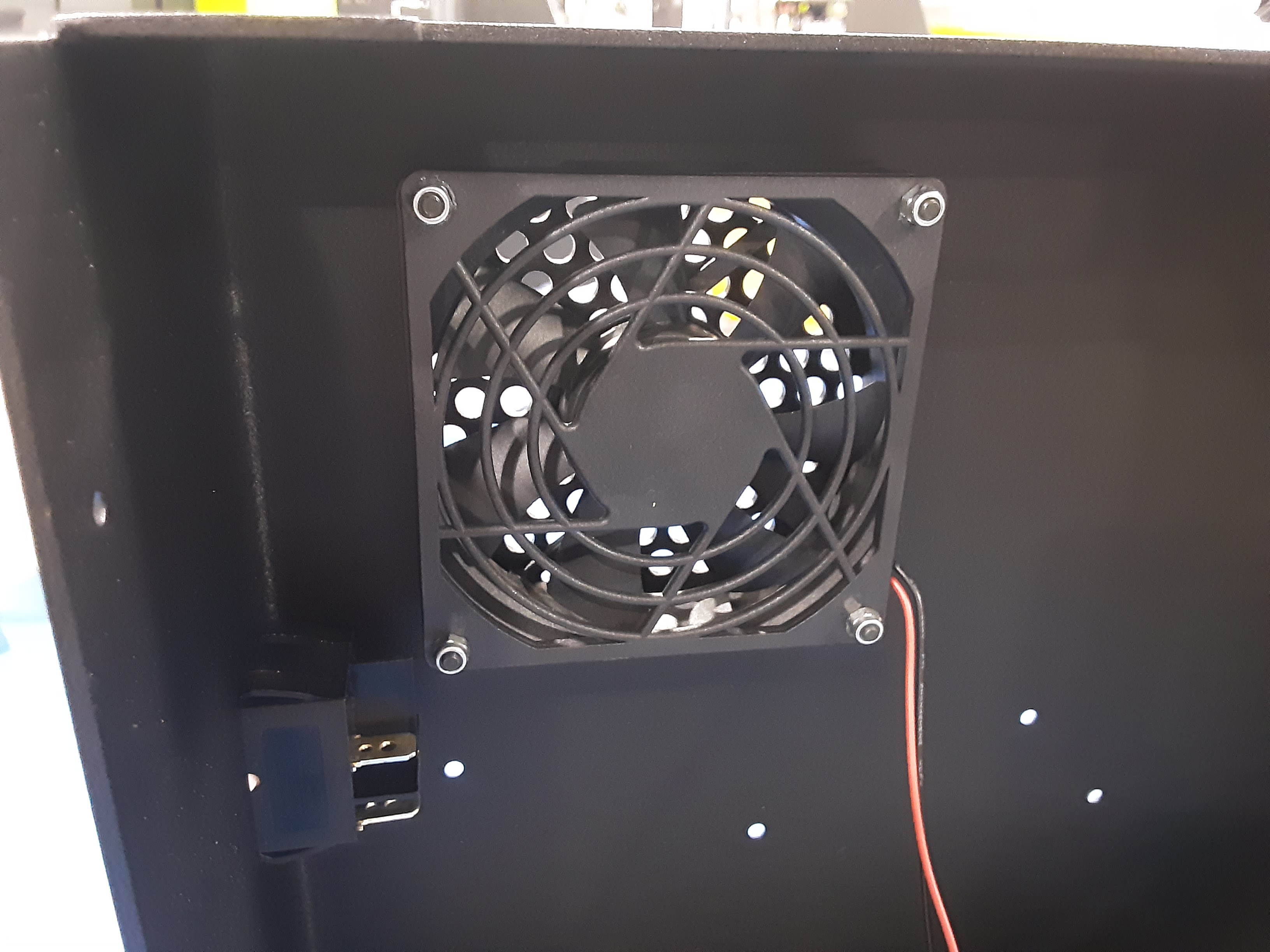
2E) Grab EL-HR0227 x1, EL-HR0109 x1, HD-BT0206 x4, and HD-NT0001 x4.
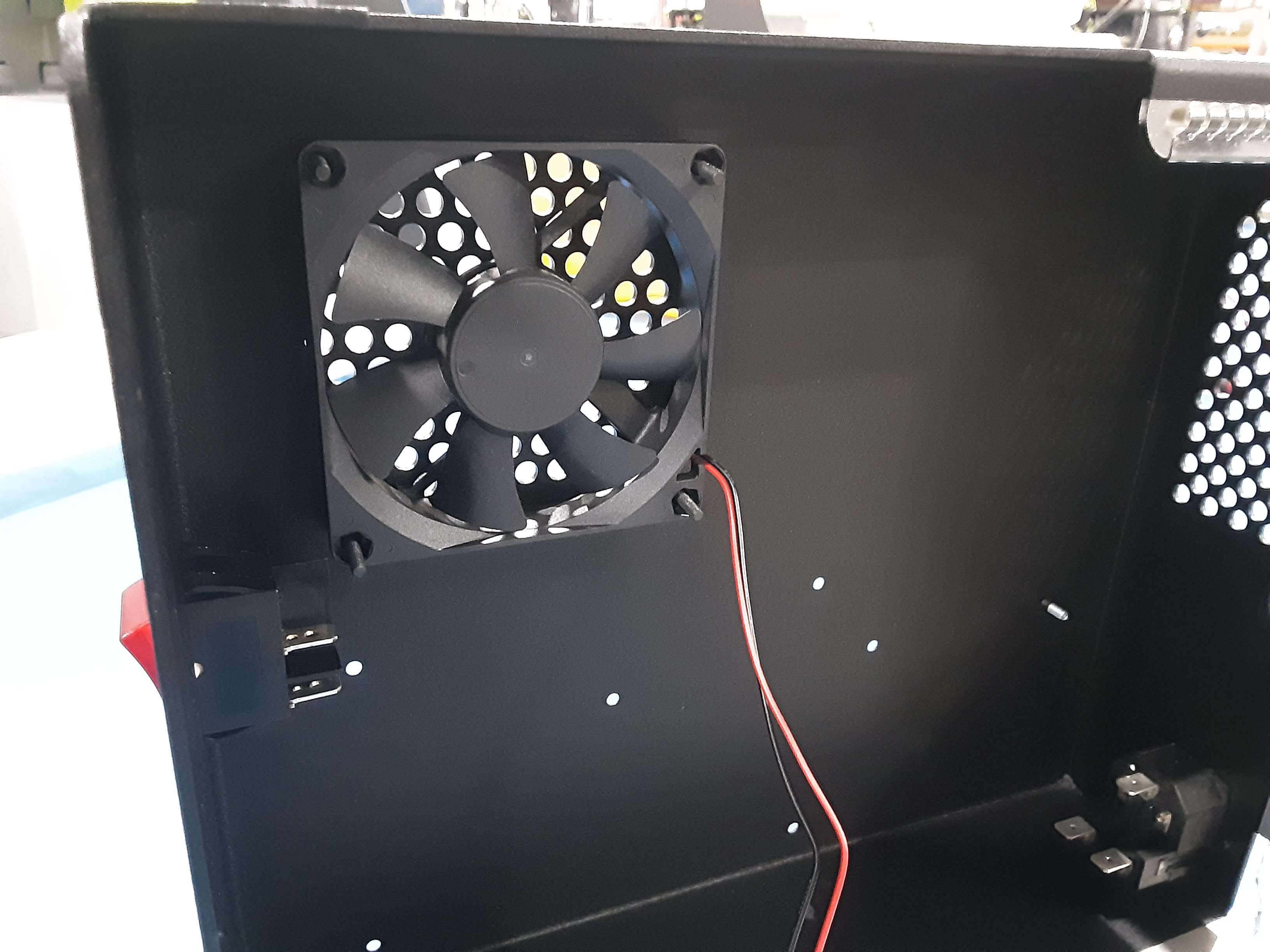
2F) Attach EL-HR0227 and EL-HR0109 to PP-FP0242 using HD-BT0206 x4 and HD-NT0001 x4. Ensure proper orientation of the fan.
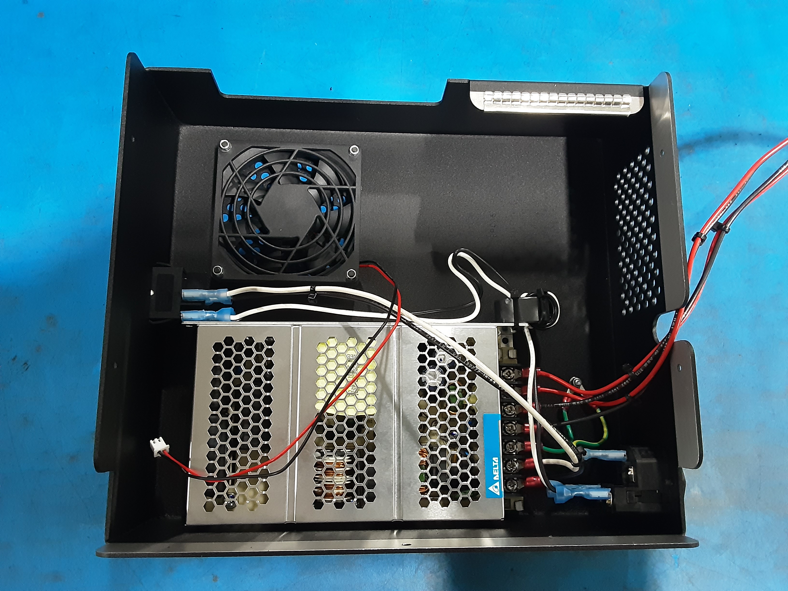
Power Supply
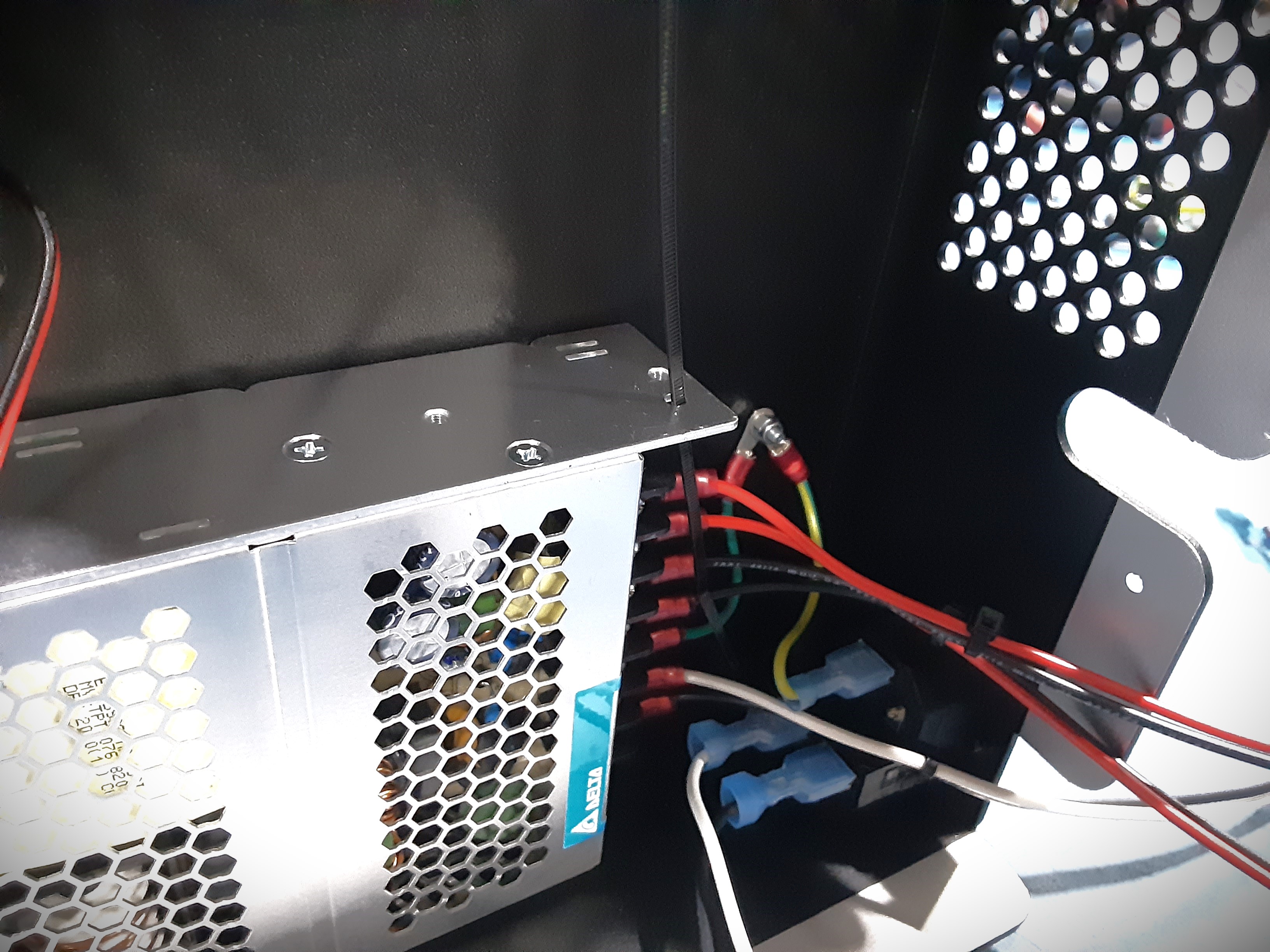
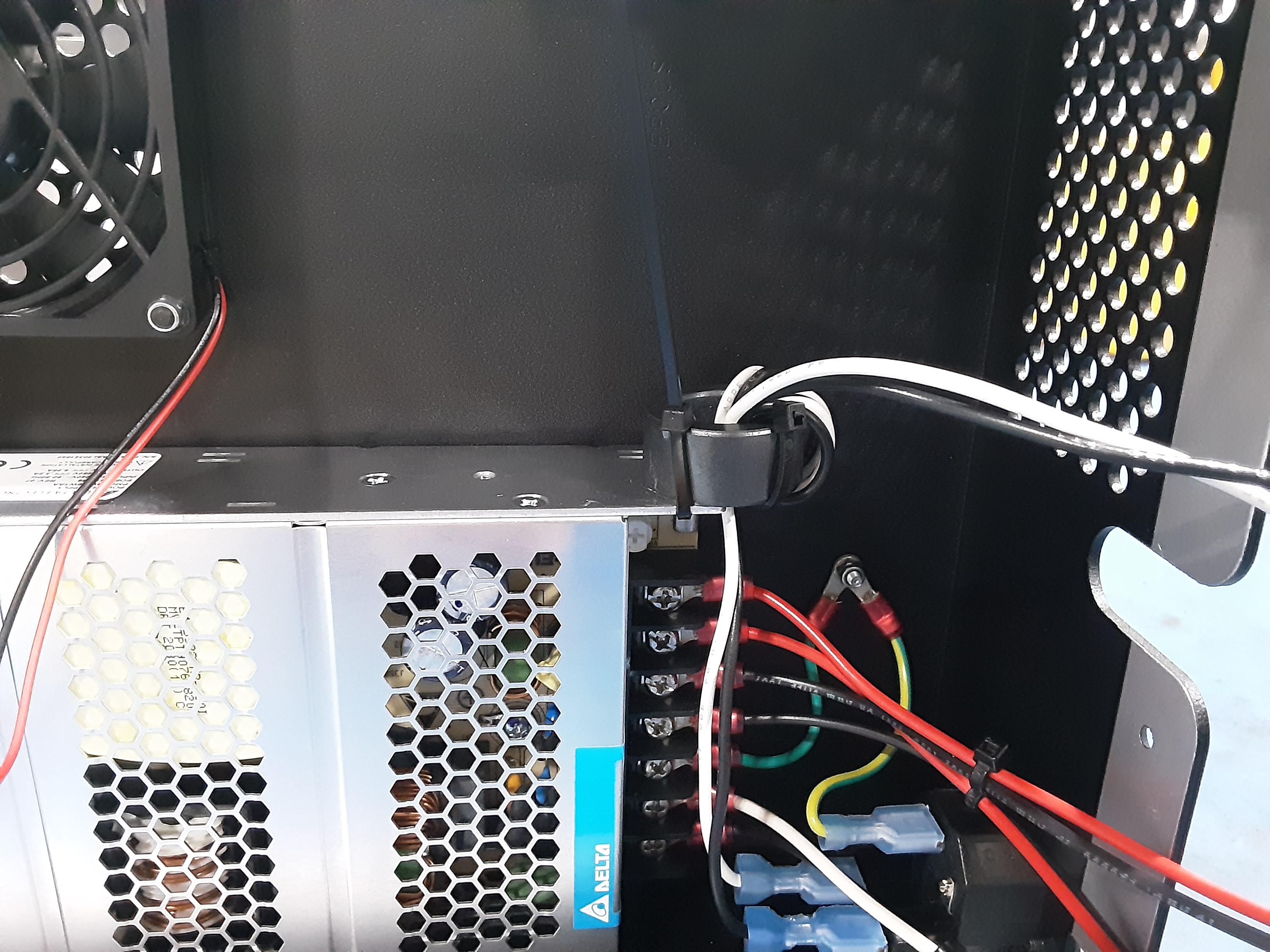
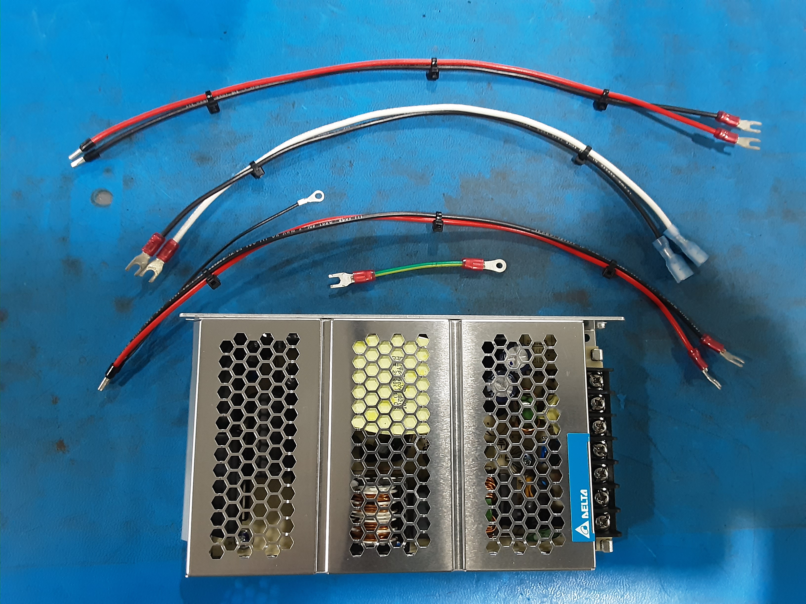
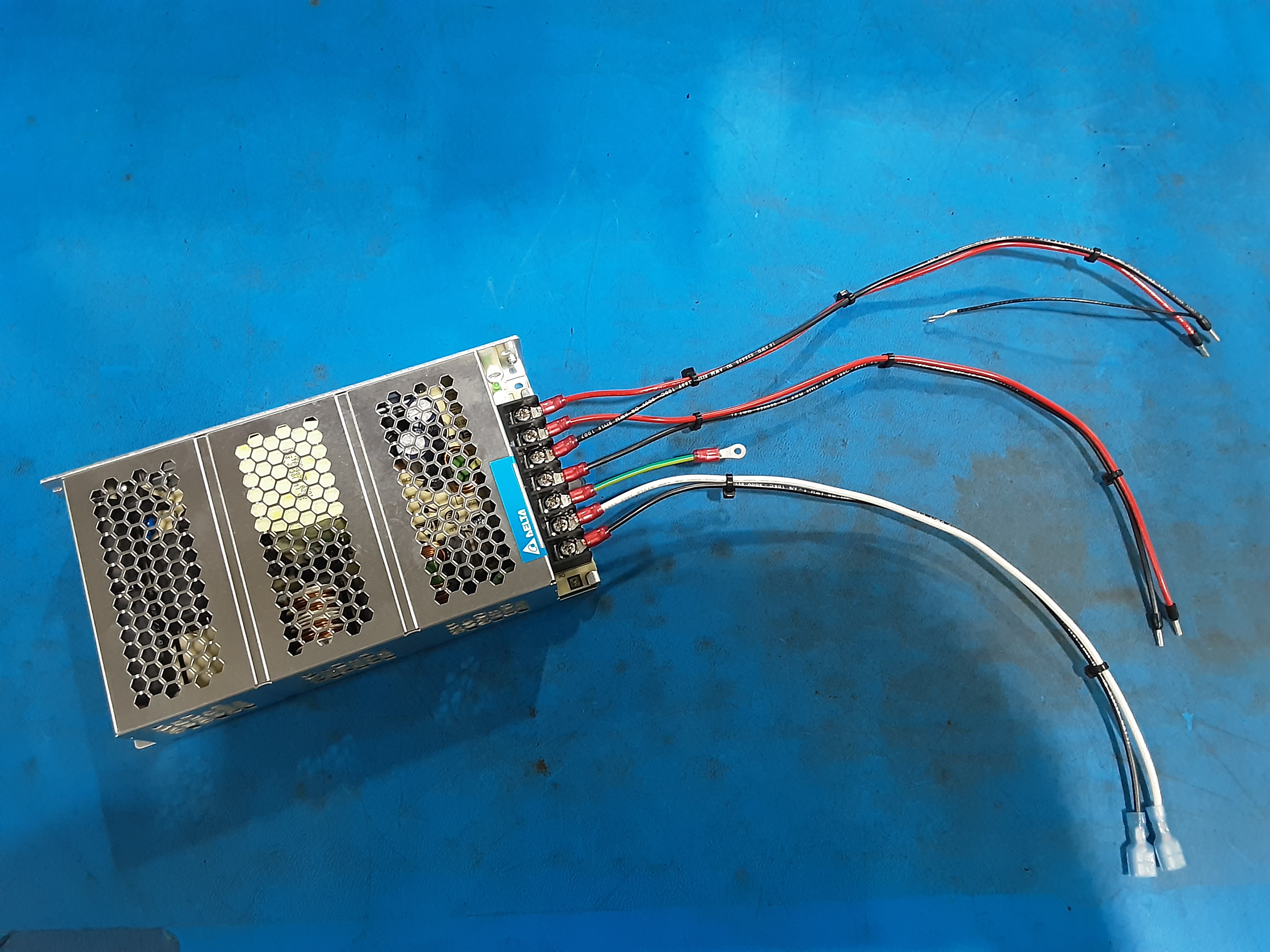
3A) Grab EL-PS0025 x1, EL-HR0216 x1, EL-HR0217 x1, EL-HR0225 x1, and EL-HR0226 x1.
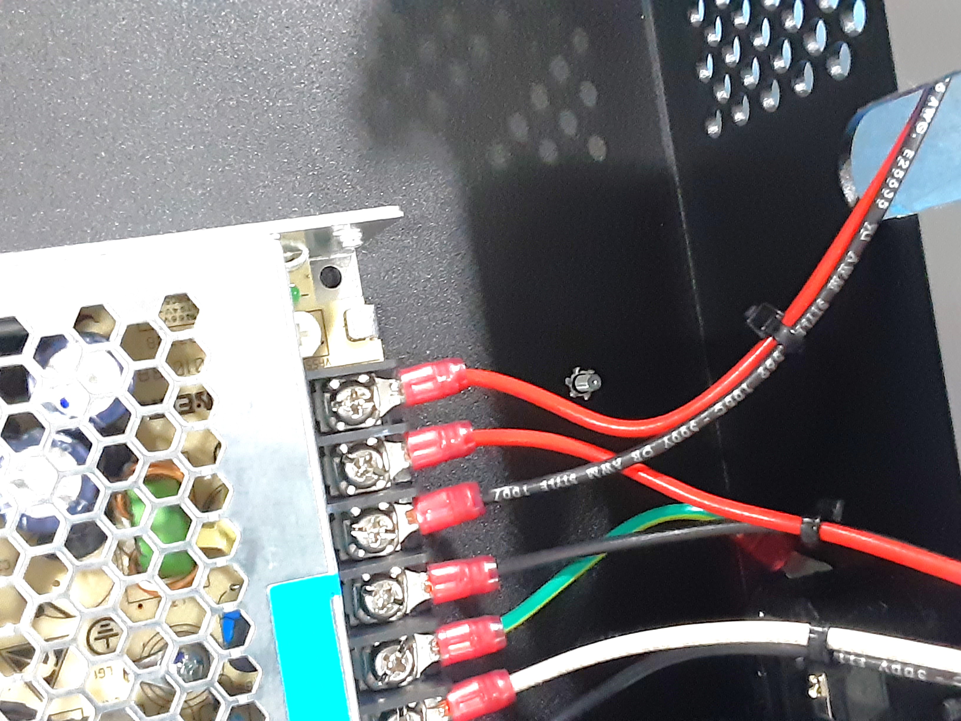
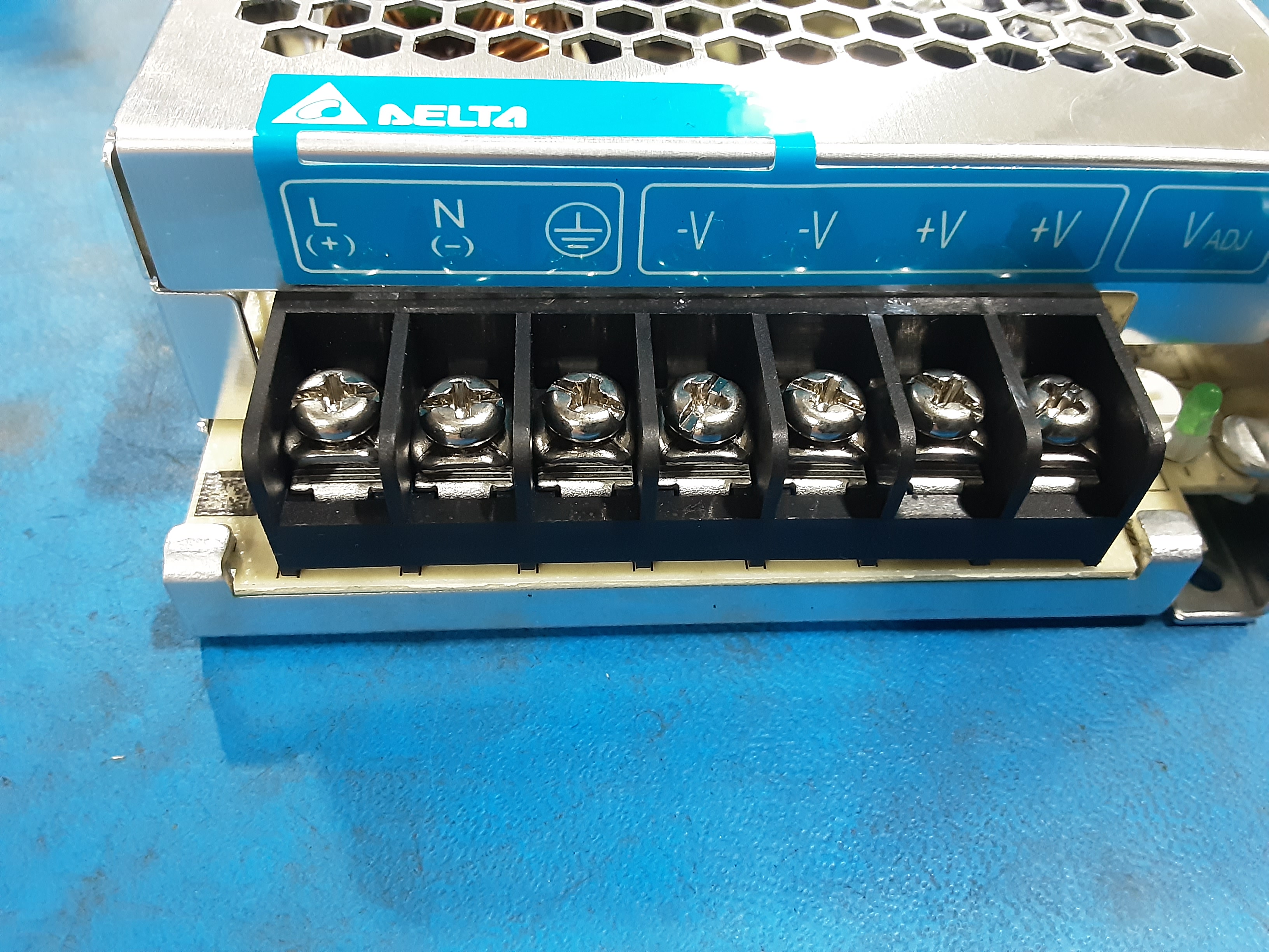
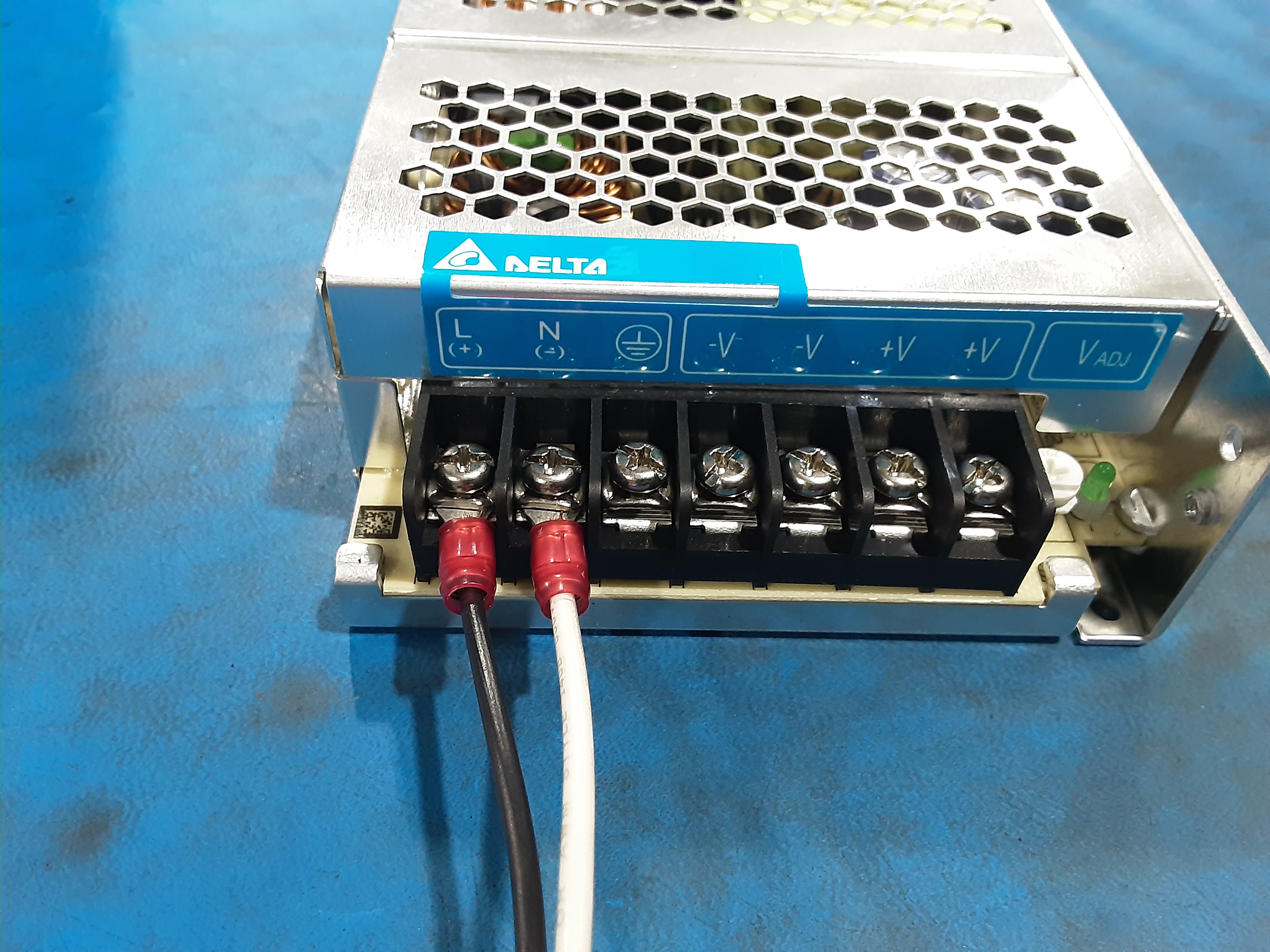
3B) Loosen the seven clamp screws on EL-PS0025.
3C) Insert the “U” shaped terminals of EL-HR0225 into the shown clamps on EL-PS0025 and tighten the screw to secure the terminals.
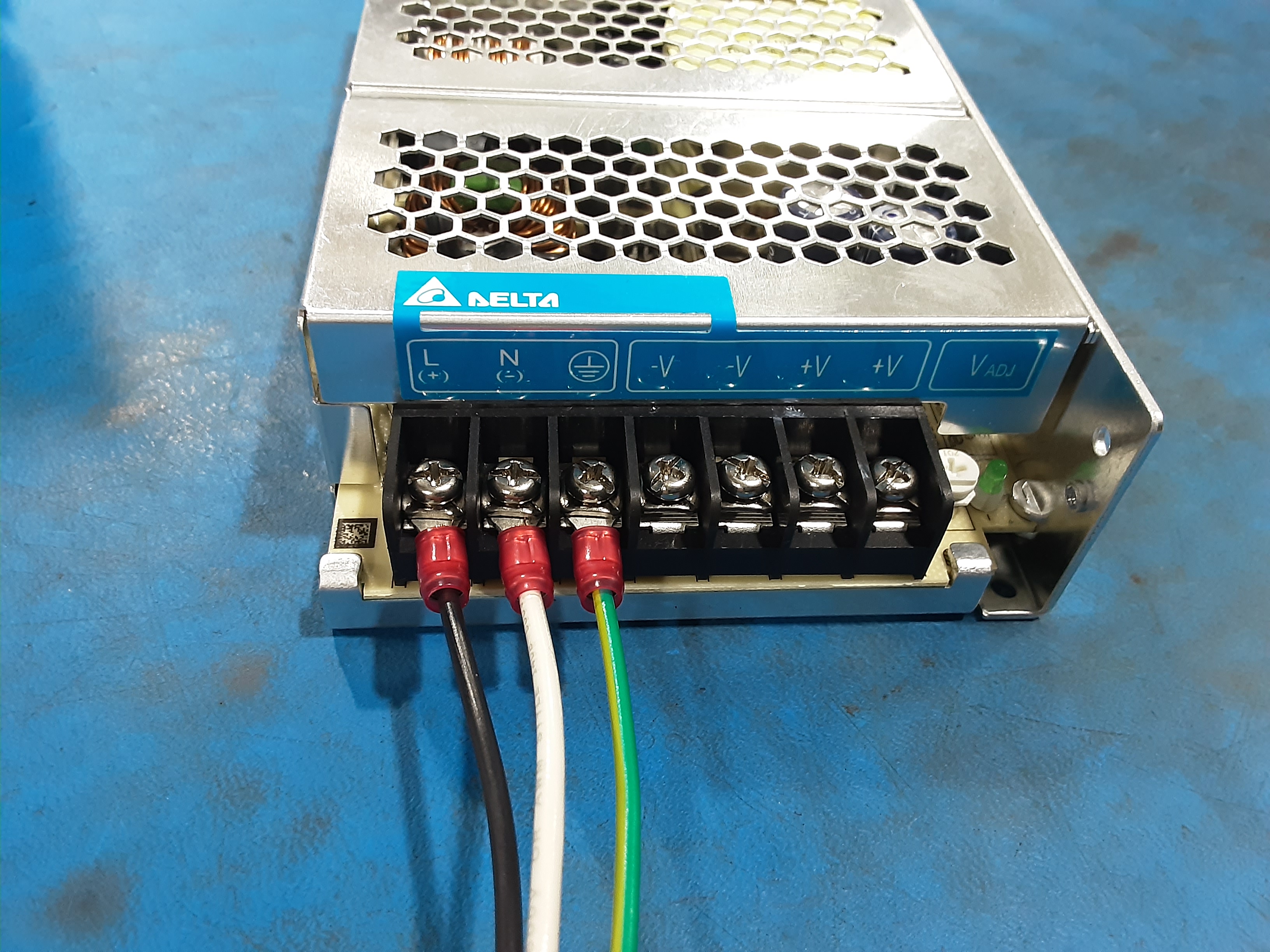
3D) Insert the “U” shaped terminal of EL-HR0226 into the shown clamps on EL-PS0025 and tighten the screw to secure the terminal.
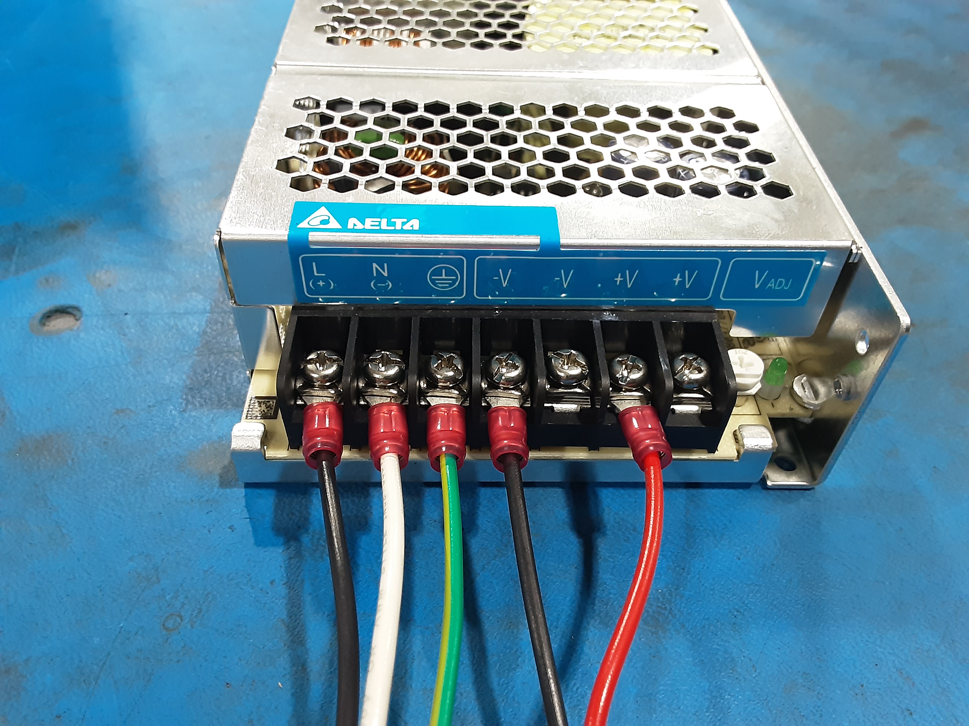
3E) Insert the “U” shaped terminals of EL-HR0217 into the shown clamps on EL-PS0025 and tighten the screw to secure the terminals.
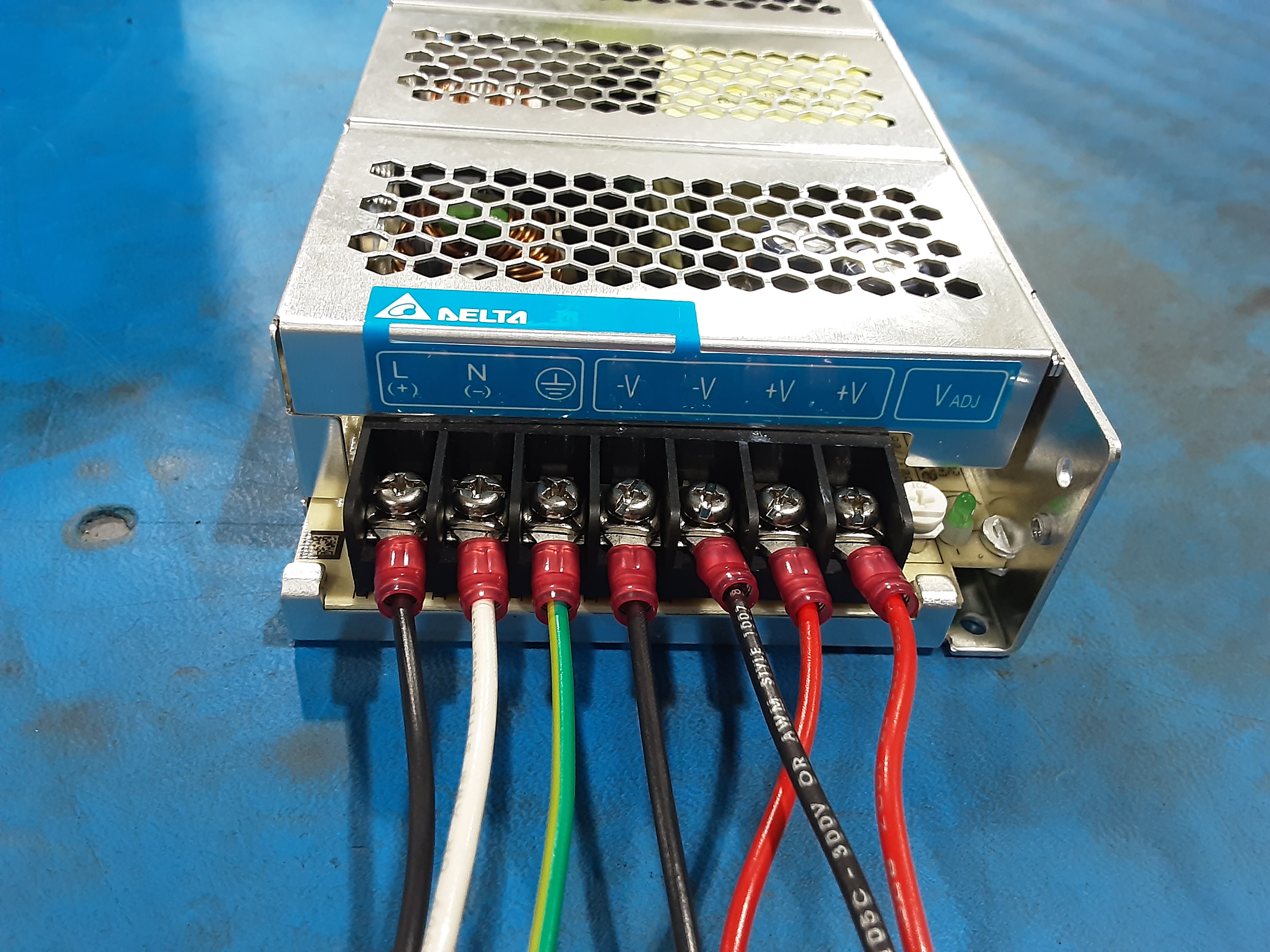
3F) Insert the “U” shaped terminals of EL-HR0216 into the shown clamps on EL-PS0025 and tighten the screw to secure the terminals.
3G) Double check the wires to ensure they are in the correct locations.
Final Steps
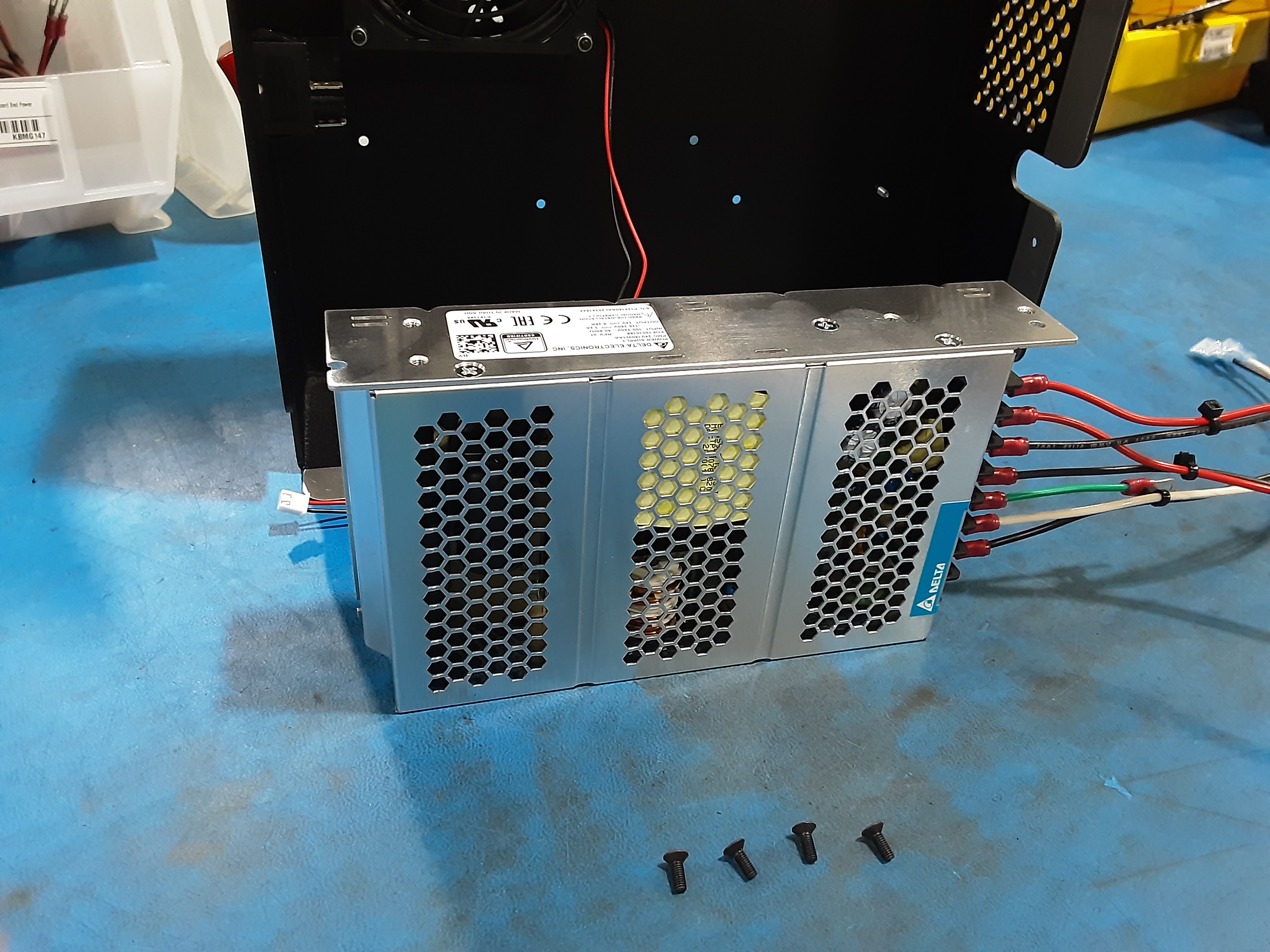
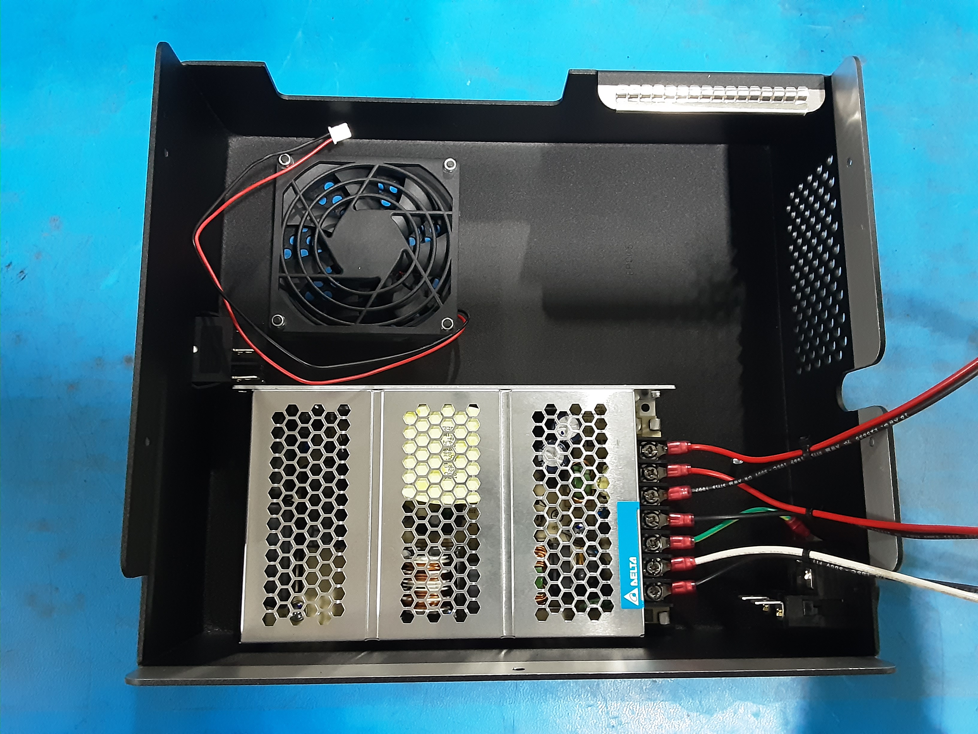
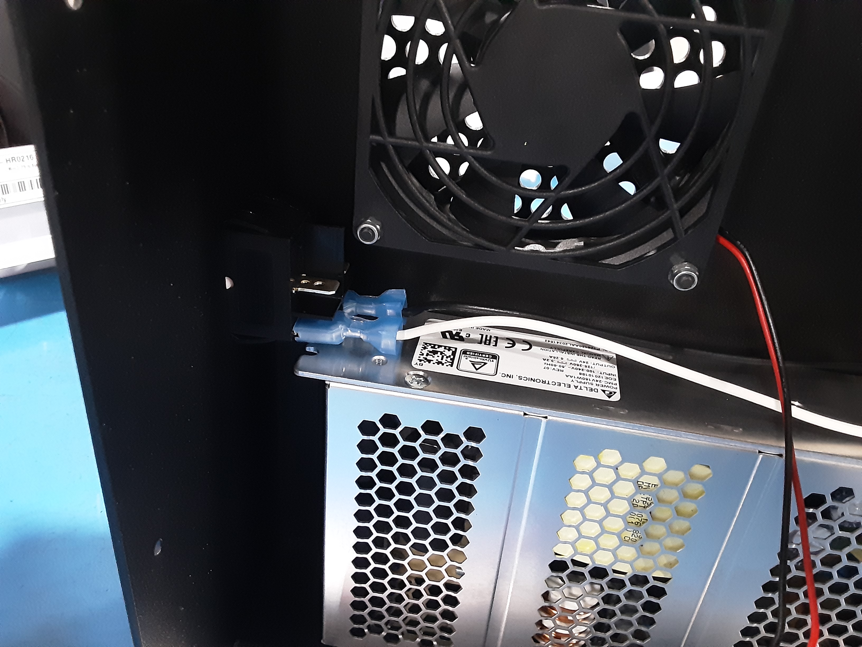
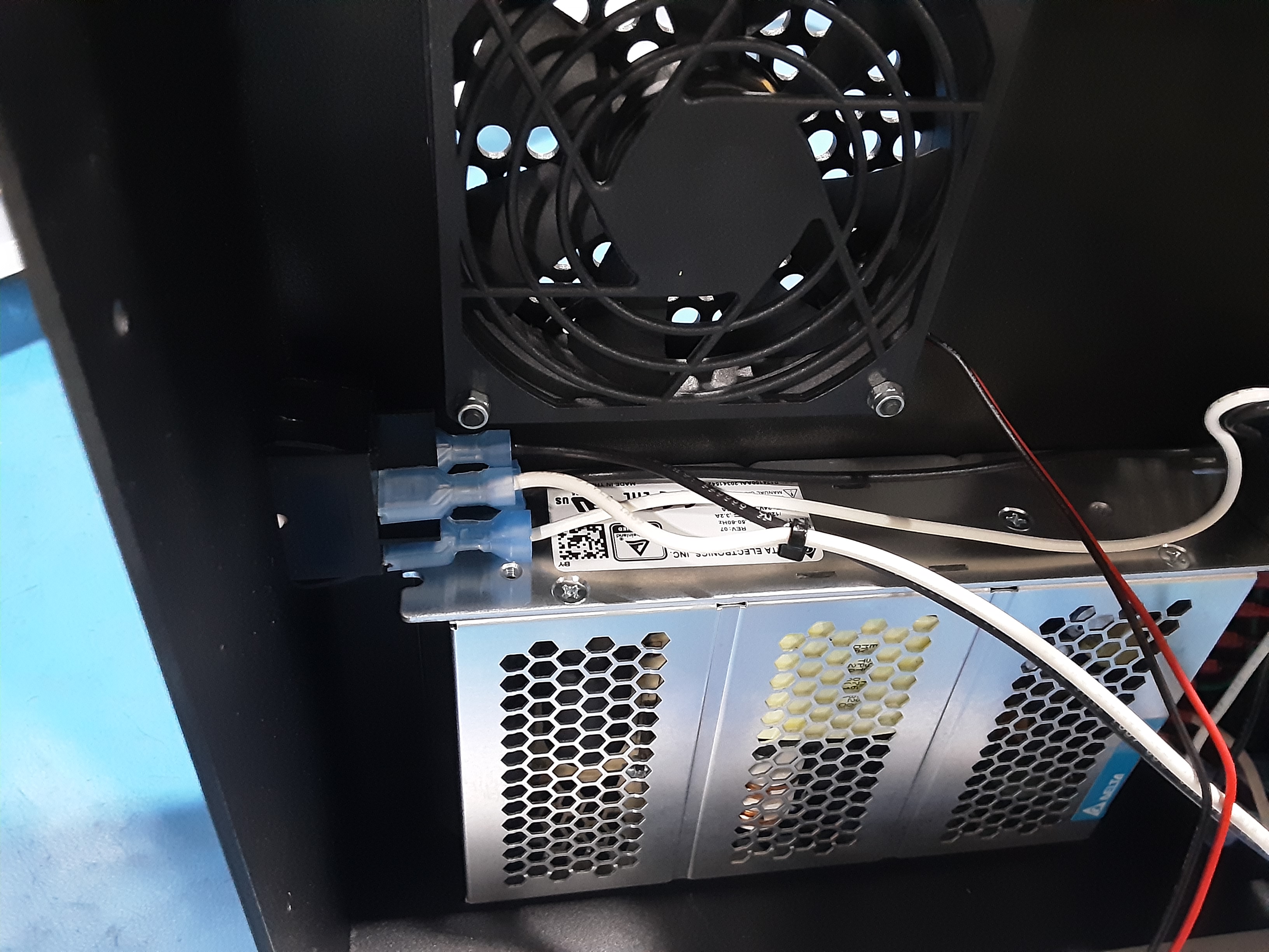
4A) Attach EL-PS0025 to PP-FP0242 using HD-BT0130 x4
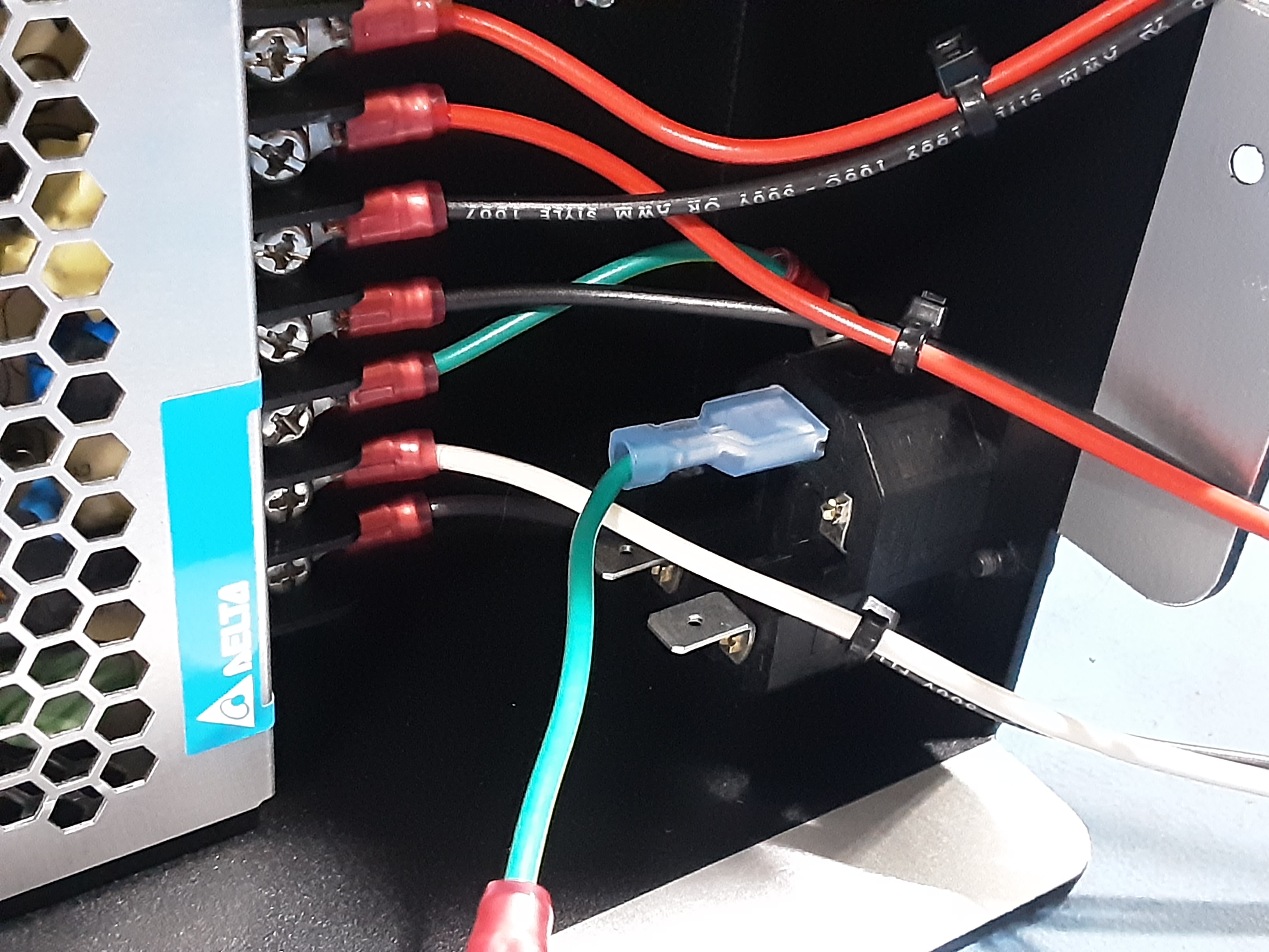
4B) Attach the spade terminal on AS-CB0079 where shown on PP-MP0028.
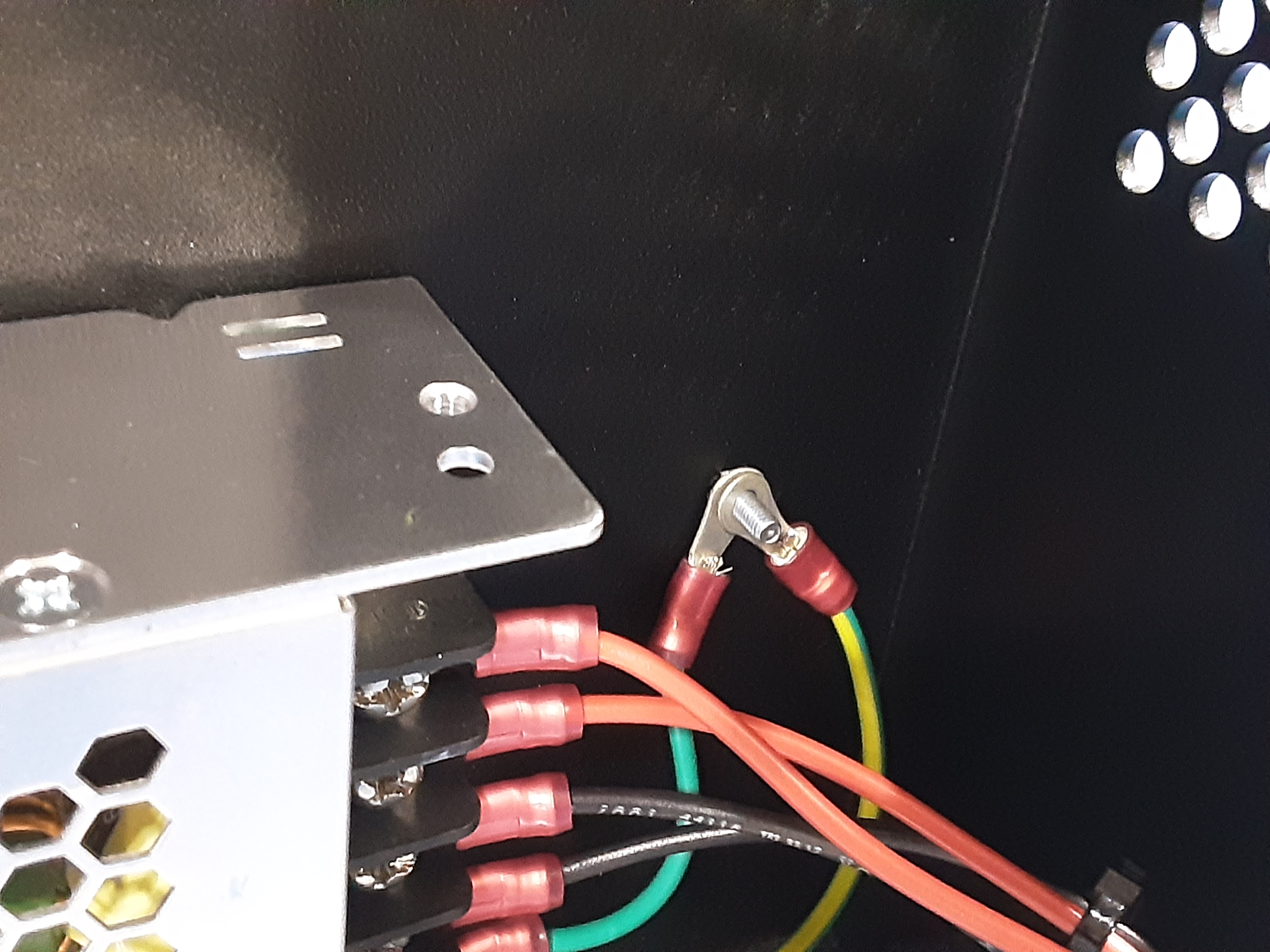
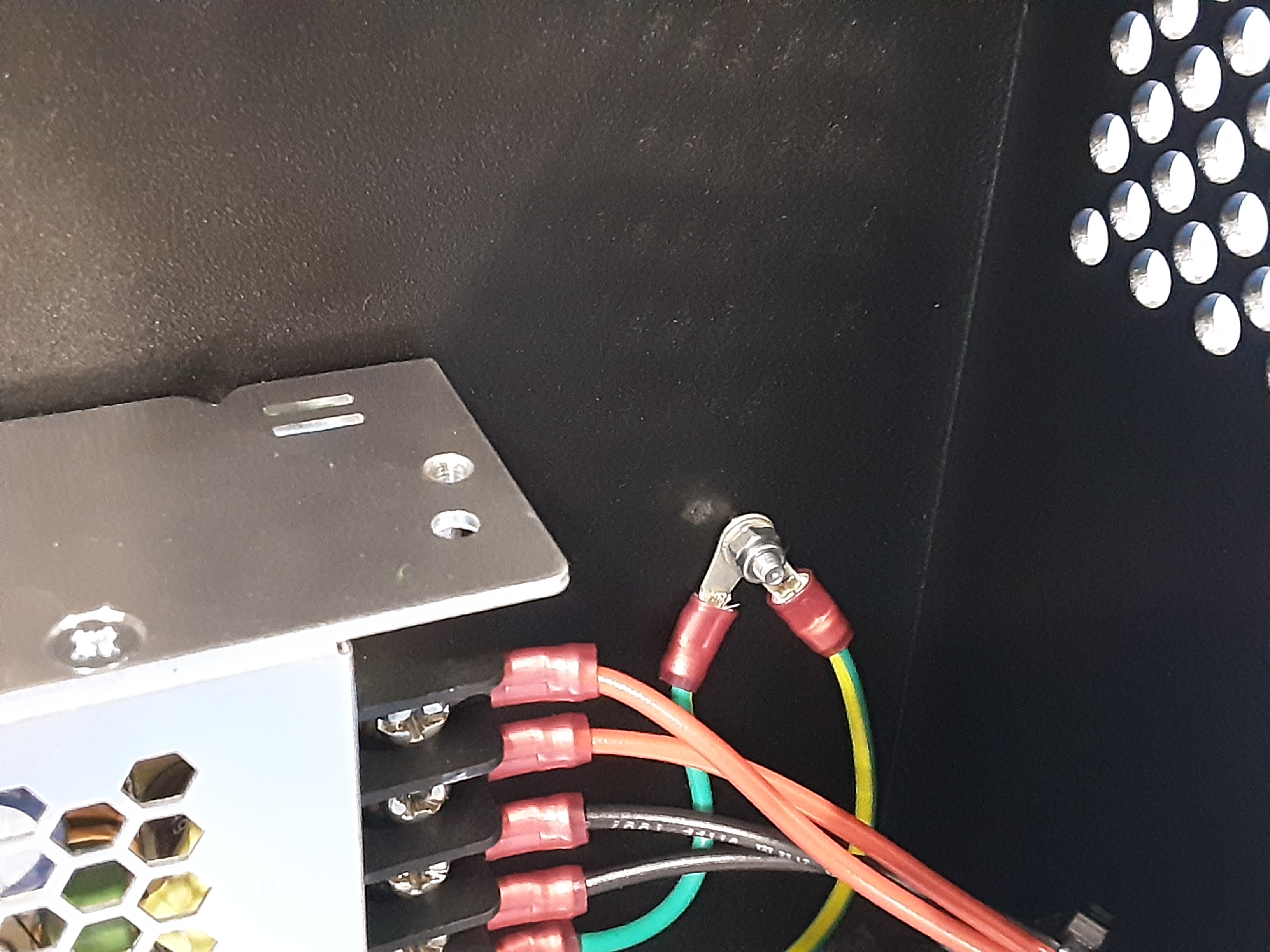
4C) Place HD-WA0035 on the ground screw in PP-FP0242.
4D) Place the ring terminal of AS-CB0079 and EL-HR0226 on the ground screw.
4E) Use HD-NT0001 x1 to secure the terminals.
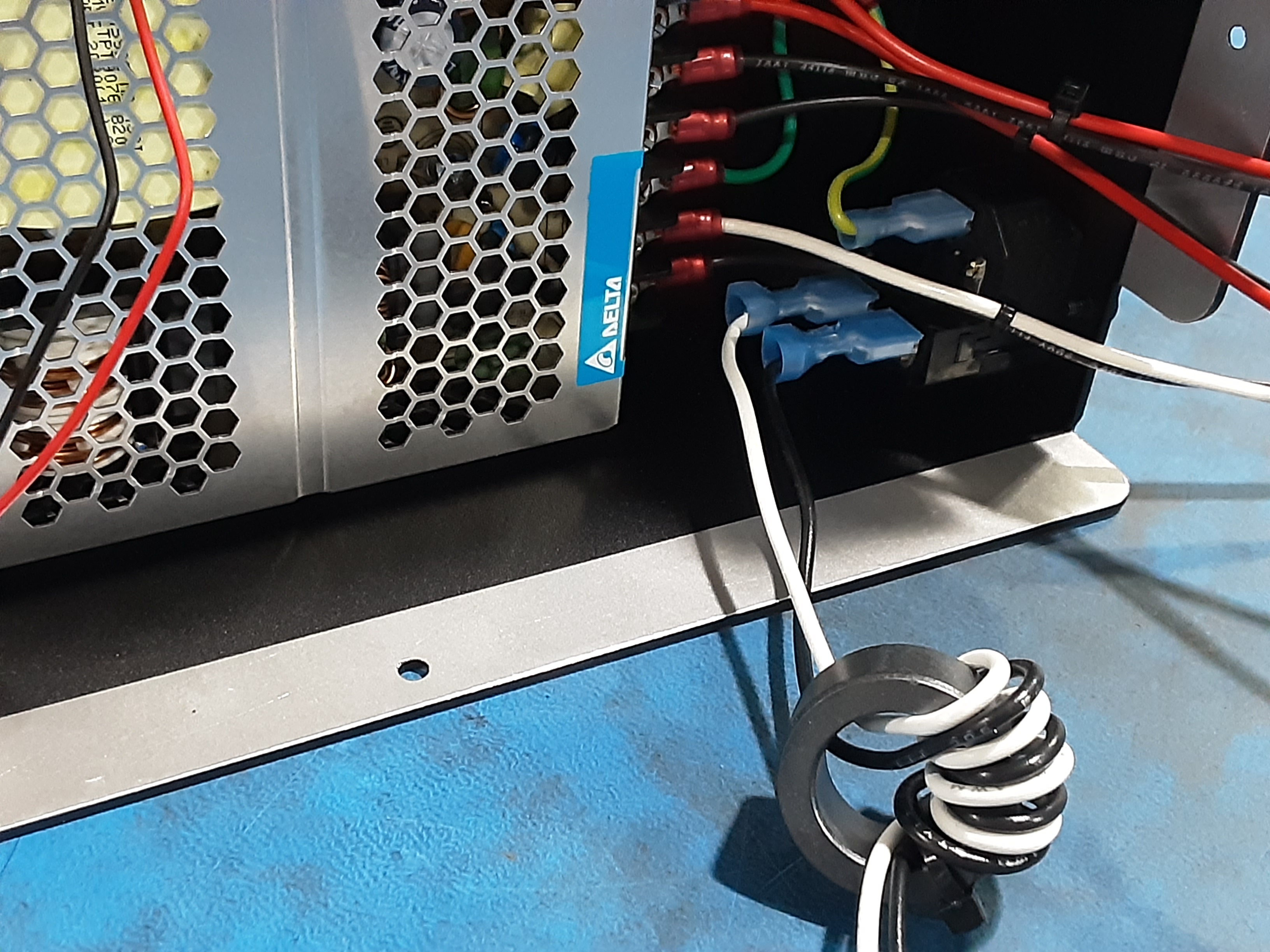
4F) Attach the shorter wire length side spade terminals of AS-CB0073 to PP-MP0028 as shown.
4G) Attach the Tubular Bead from AS-CB0073 to EL-PS0025 using HD-MS0058 x1. Try to get the Tubular Bead to sit as flat as possible on PP-PS0025.
4H) Attach the longer wire length side spade terminals of AS-CB0073 to EL-SW0023 as shown.
4I) Attach the spade terminals of EL-HR0225 to EL-SW0023 as shown.