Open HardwareAssembly Instructions
Guides for installation and assembly of the LulzBot line of products made by FAME 3D LLC.
Guides for installation and assembly of the LulzBot line of products made by FAME 3D LLC.
Parts:
2x- Ninjaflex damper (PP-GP0237)
1x- X Idler (AS-PR0018)
1x- X Motor with threaded inserts installed (AS-PR0014)
1x- Z Lower Left with 608 bearing and threaded inserts installed (AS-PR0016)
1x- Z Lower Right with 608 bearing and threaded inserts installed (AS-PR0020)
2x- Lead screw (HD-RD0048)
2x- 10mm OD, 500mm long smooth rod (HD-RD0018)
2x- Z nut (HD-NT0355)
1x- GT2 Timing Pulley (HD-MS0033)
2x- M3x6 Set Screws (HD-BT0012)
4x- M5x16 BHCS (HD-BT0175)
4x- M3x12 BHCS (HD-BT0146)
4x- M3 Black washer (HD-WA0038)
4x- M2x10 SHCS (HD-BT0107)
4x- M2 washer (HD-WA0012)
2x- SPDT Roll switch (EL-SW0022)
1x- NEMA17 Moons’ Motor (EL-MT0029)
2x- 608 Bearings (HD-MS0282)
3x- M8 Washers (HD-WA0006)
1x- M8 Nyloc Nut (HD-NT0002)
1x- M8x40 BHCS (HD-BT0061)
Tools:
13mm Open End Wrench
4mm Hex Driver
1.5mm Hex Driver
2mm Hex Driver
3mm Hex Driver
1.3mm Hex Driver


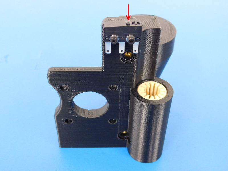
Install two (2) switches (EL-SW0022), noting proper switch orientation, to the X End Left (AS-PR0014) with two (2) M2x10 SHCS (HD-BT0107) with washers (HD-WA0012) for each switch; tighten to finger tight. Refer to pictures for orientation.
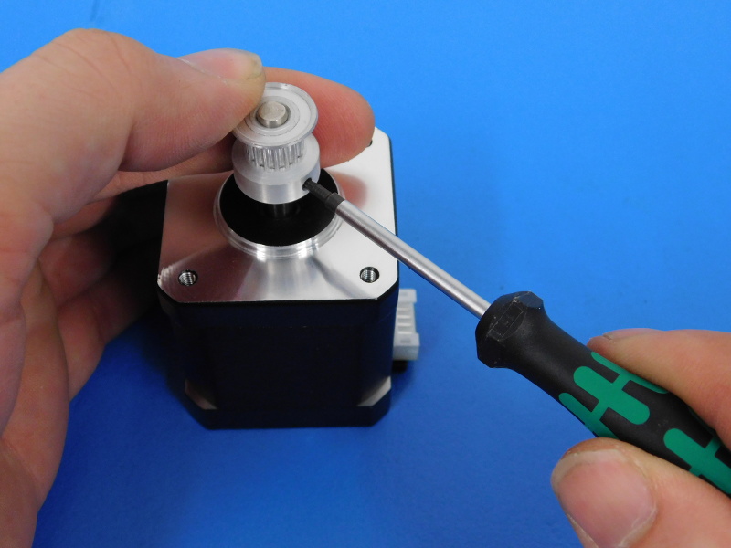
Install a Timing Pulley (HD-MS0033) to the shaft of a Motor (EL-MT0029);
Use the X-Motor Pulley Spacer to set the height of the pulley on the shaft to 7mm. The first set screw to be tightened must be tightened to the flat side of the motor shaft. Tighten both set screws firmly with the 1.3mm Hex Driver.
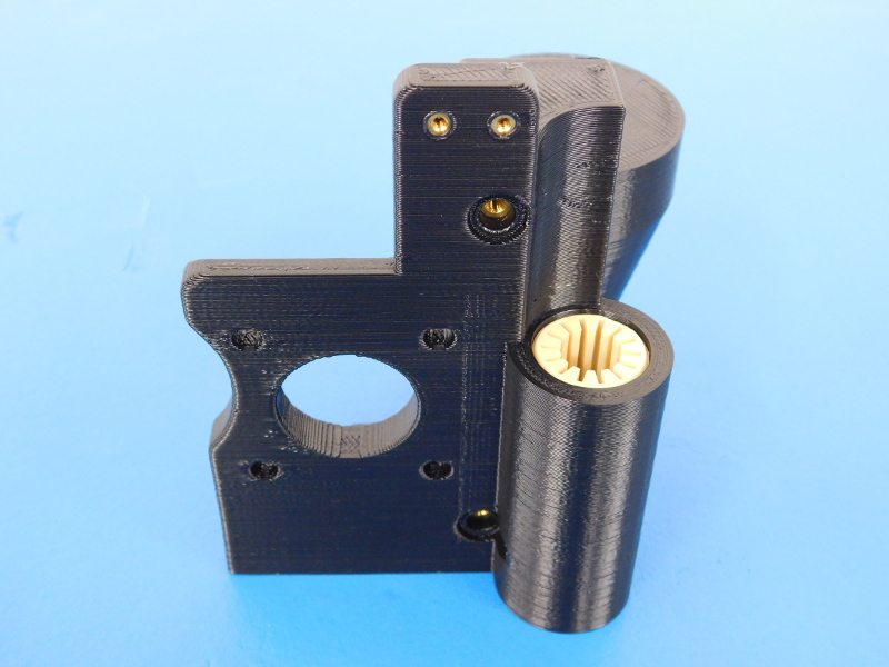
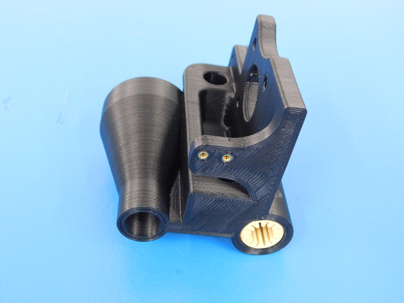
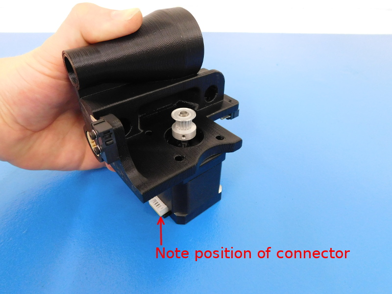
Ensuring that the motor’s connector faces the bottom of the part, attach the Motor to the mount using four (4) M3x12 BHCS (HD-BT0146) with washers (HD-WA0038); tighten firmly.
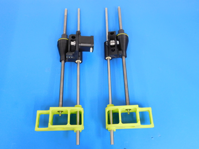
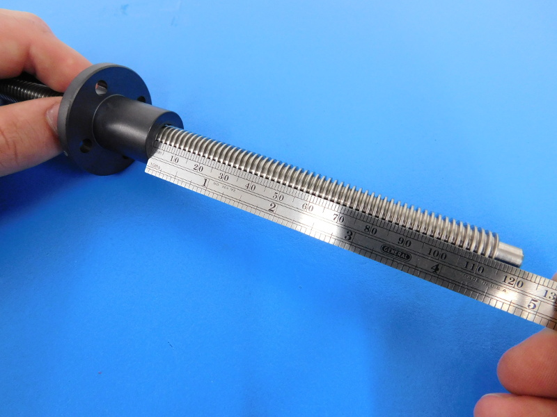
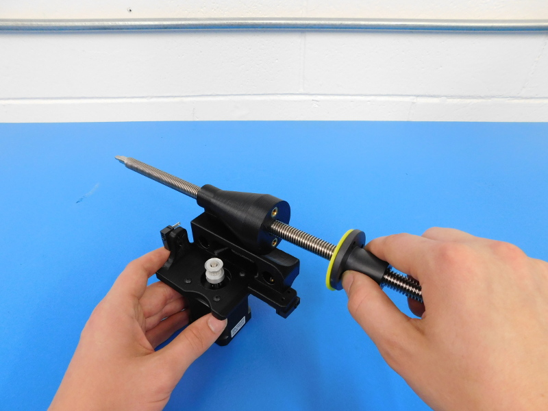
Thread the Z-Nut (HD-NT0355) Flange side down onto the Z-axis Lead Screw (HD-RD0048) about 120mm from the top end of the screw.
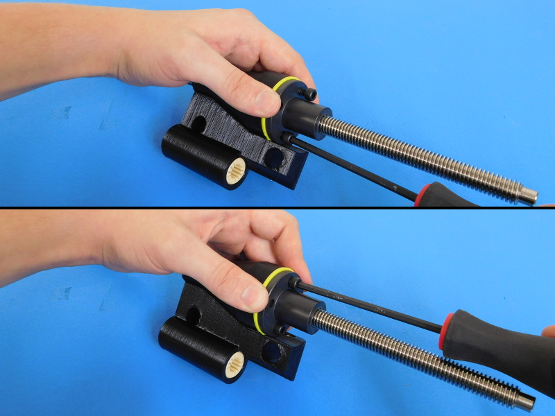
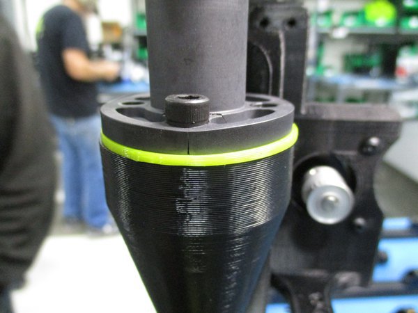
Slide the X-Motor Assembly onto the lead screw along with a NinjaFlex Gasket (PP-GP0237). Then use two (2) M5X16 SHCS (HD-BT0175) to secure the motor assembly to the Z-Nut. TIGHTEN FINGER TIGHT. Do not over-tighten the Z-Nut as it cracks easily. (See Image)
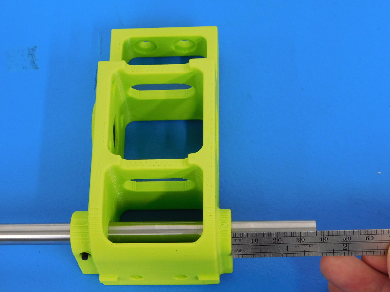
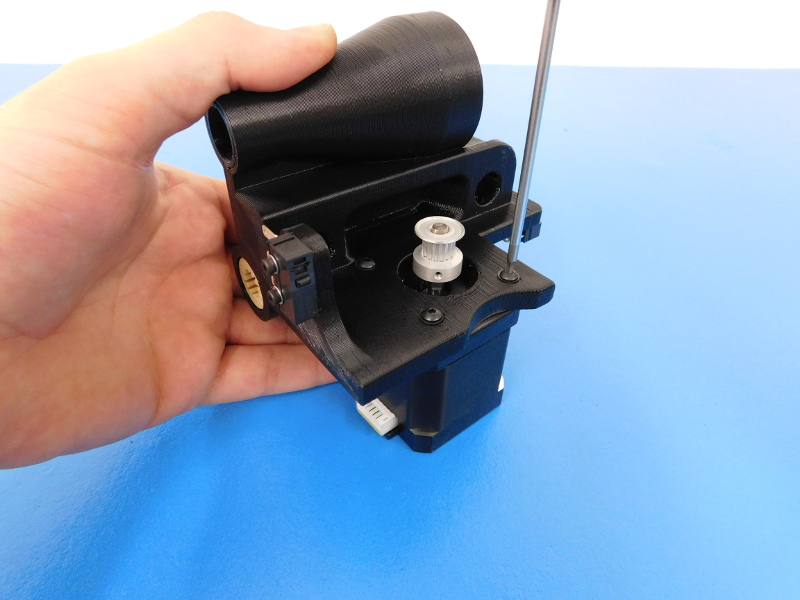
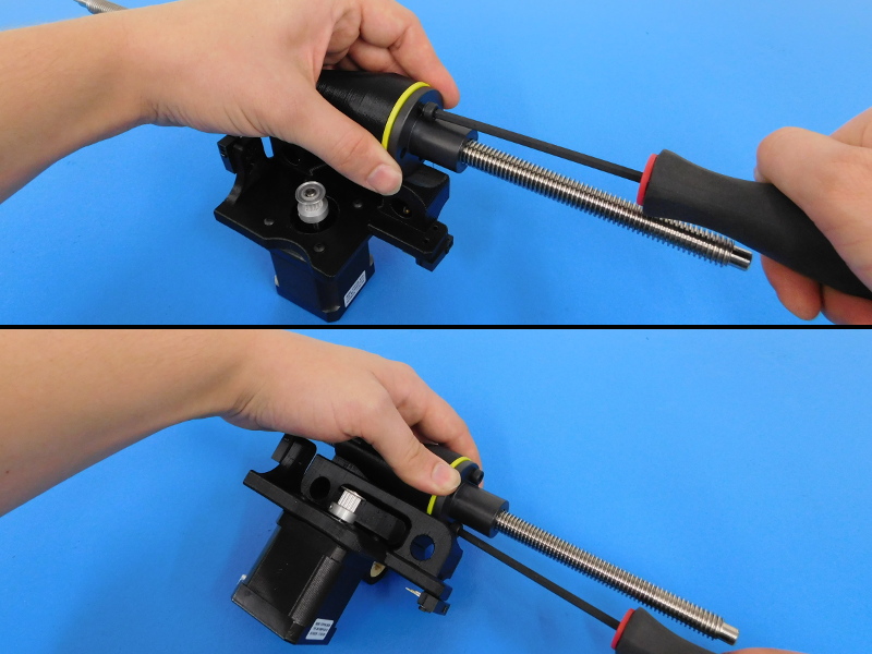
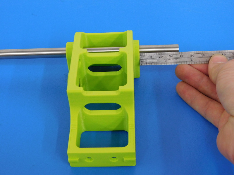
Insert the 500mm Smooth Rod (HD-RD0018) into the left Z Lower Left (AS-PR0016) so that it protrudes from the motor flange side about 37mm.
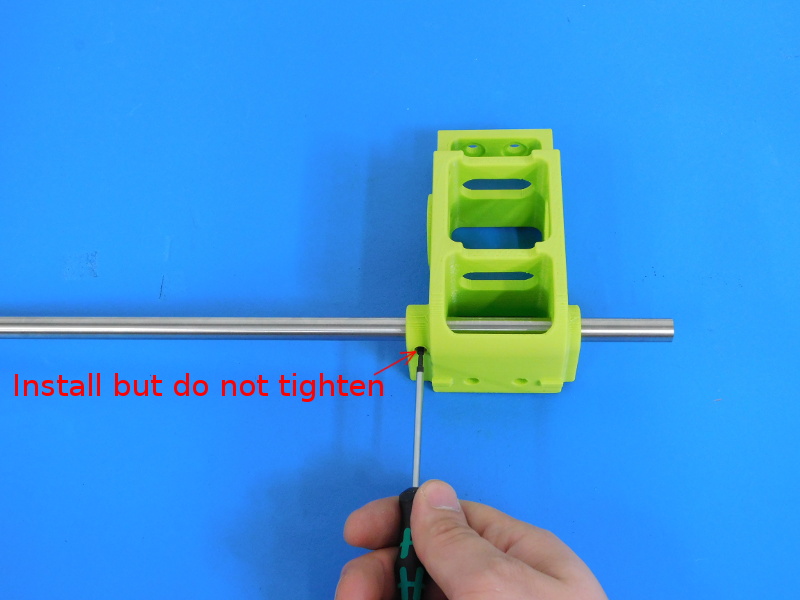
Install but do not secure the M3 Set Screw (HD-BT0012).
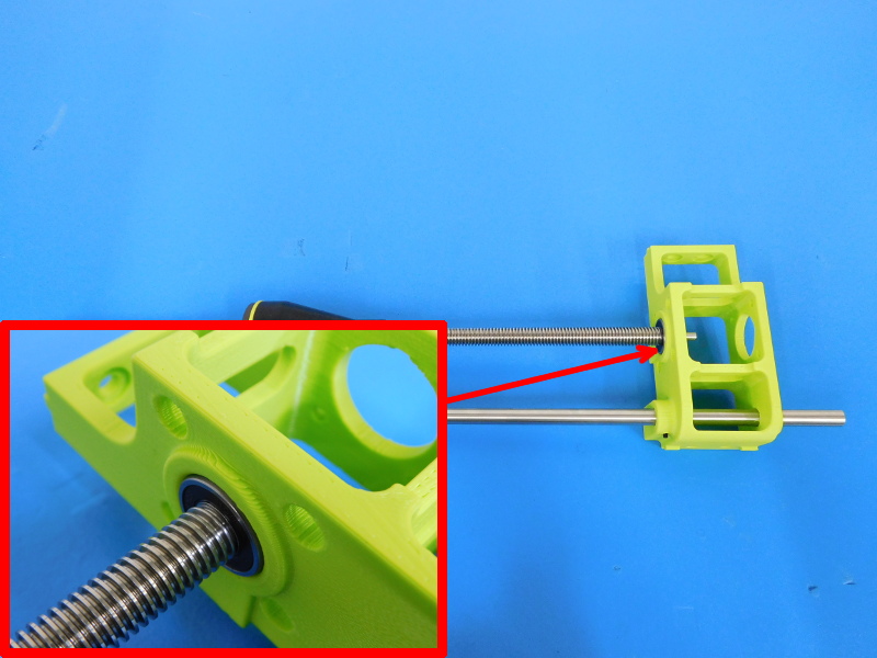
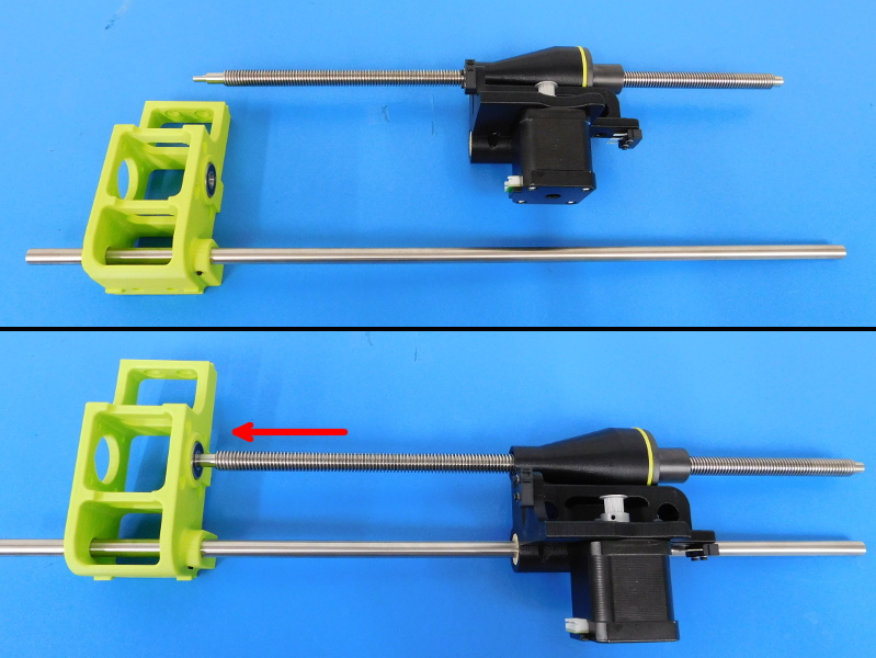
Slide the X motor assembly onto the 500mm Smooth Rod so that the lead screw shoulder slides into the support bearing in the Z Lower Left.


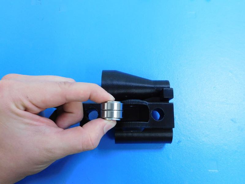
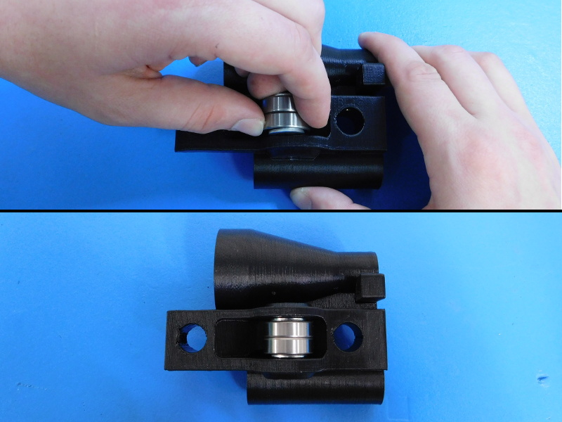
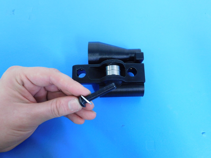
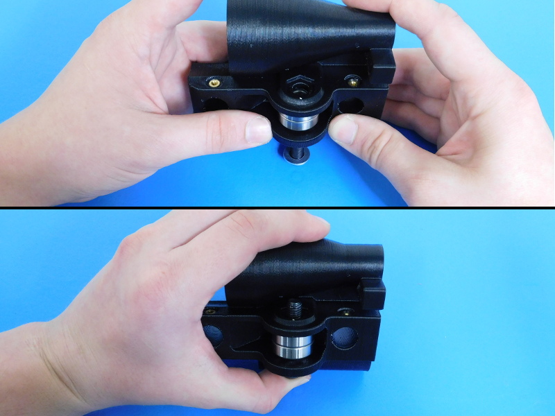
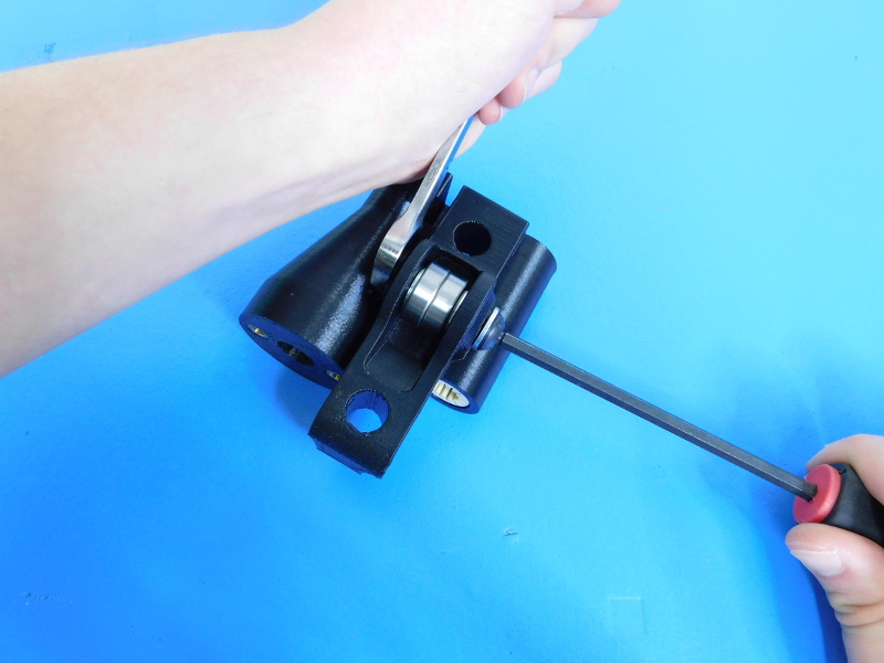
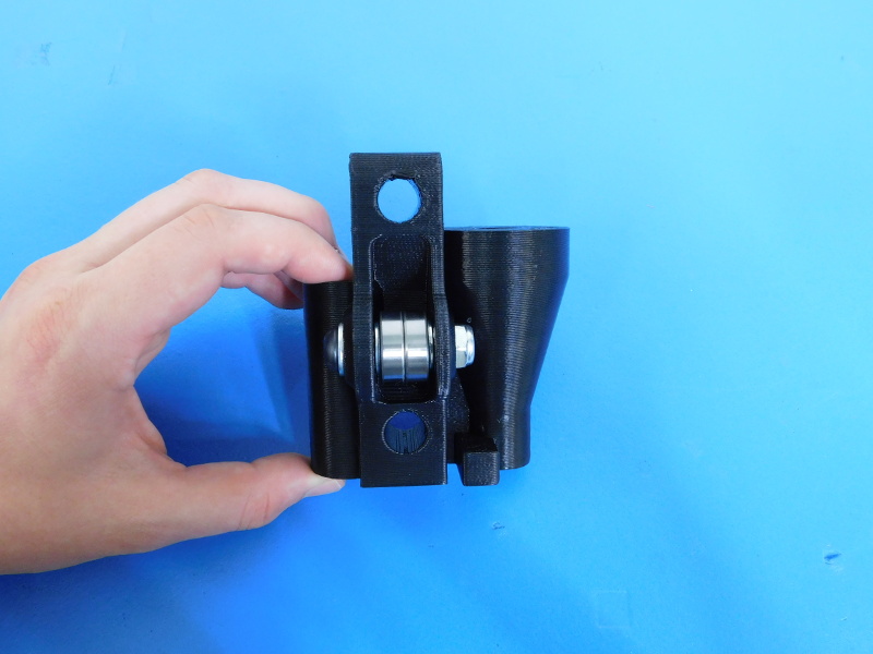
Place two bearings (HD-MS0282) against each other, place a M8 Washer (HD-WA0006) on both sides of the stacked bearings. Position the bearing/washer stack in between the two flanges of the X Idler (AS-PR0018) Place a M8 washer on the M8x40 BHCS (HD-BT0061), run the M8x40 BHCS through the flanges, washers, and bearings; Install the M8 Nyloc and secure. 1-2 threads of the M8 BHCS should extend beyond the end of the Nyloc nut, the bearings should spin but not too freely.
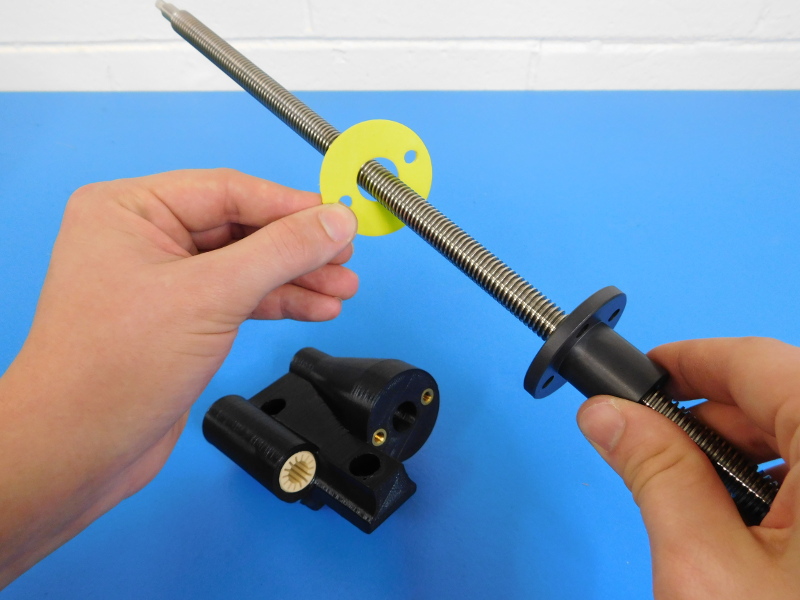
Thread the Z-Nut (HD-NT0355) Flange side down onto the Z-axis Lead screw (HD-RD0048) about 120mm from the top end of the screw.
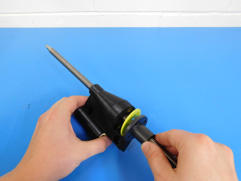
Slide the X-Axis Idler (AS-PR0018) onto the screw along with a NinjaFlex Gasket (PP-GP0237). Then use two (2) M5X16 SHCS (HD-BT0175) to secure the motor assembly to the Z-Nut. TIGHTEN FINGER TIGHT. Do not over-tighten the Z-Nut as it cracks easily. (See Image)
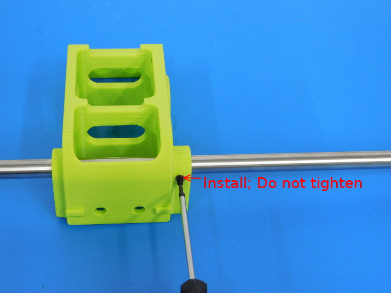
Insert the 500mm Smooth Rod (HD-RD0018) into the Z Lower Right (AS-PR0020) so that it protrudes from the motor flange side about 37mm.
Install but do not tighten the M3x6 Set Screw (HD-BT0012).
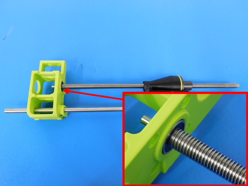
Slide the X-Idler Assembly onto the 500mm Smooth Rod so that the lead screw shoulder slides into the support bearing in the Z Lower Right.