Open HardwareAssembly Instructions
Guides for installation and assembly of the LulzBot line of products made by FAME 3D LLC.
Guides for installation and assembly of the LulzBot line of products made by FAME 3D LLC.
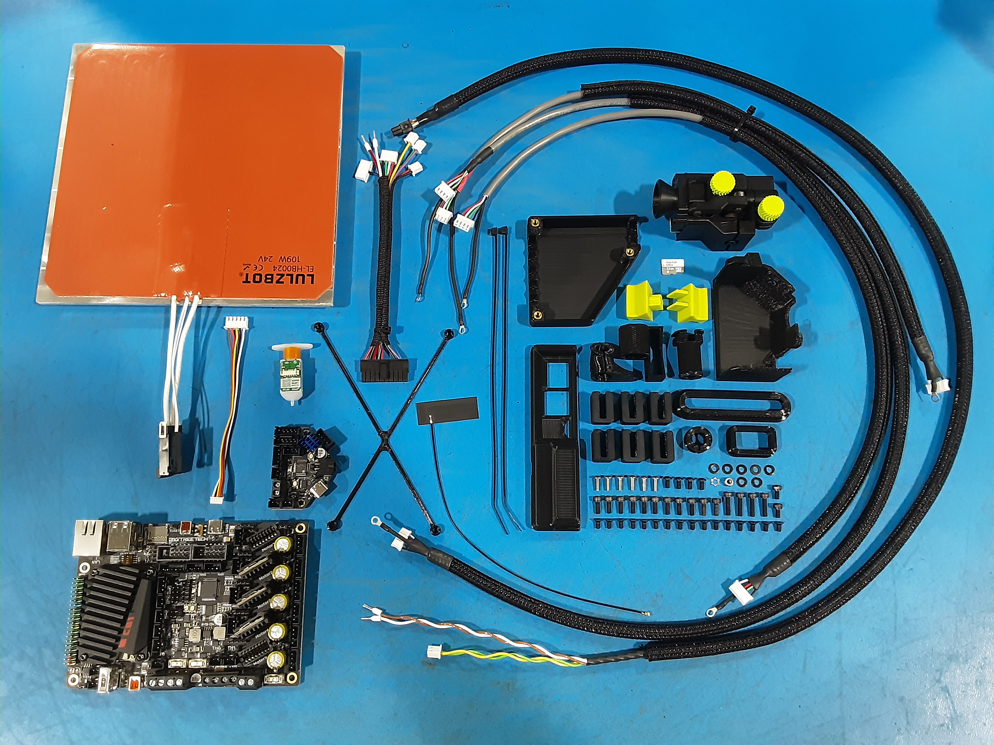
1x [AS-CB0212] Mini3 CANBus Cable
1x [AS-CB0214] Mini3, XYZ Motor Harness
1x [AS-HB0035] Mini 3 Bed Heater - Megafit
1x [AS-PR0237] JetPack Single Run Out Sensor
1x [EL-HR0212] Mini3, EBB Harness
1x [EL-HR0213] Mini3, EBB to BLTouch®, Reworked
1x [EL-MS0011] 32GB Micro SD Card Scandisk TF Ultra
4x [HD-BT0039] Metric Class 12.9 SHCS Alloy Steel, M3 x 12mm Length, 0.50mm Pitch
2x [HD-BT0045] Metric Class 12.9 SHCS Alloy Steel, M3 x 6mm Length, 0.50mm Pitch
6x [HD-BT0104] M3 x 8mm BHCS SST
16x [HD-BT0128] M3 x 6mm FHCS Black-Oxide
4x [HD-BT0140] M3 x 6 Bolt, BHCS Black Oxide
11x [HD-BT0157] Class 12.9 Alloy Steel Black-Oxide SHCS, M3 x 8mm Length, 0.50mm Pitch
2x [HD-MS0058] Wire Tie, 8" Black, pk 1000
1x [HD-NT0001] Metric Zinc-Plated Steel Nylon-Insert Locknut, M3 Size, .5MM pitch
1x [HD-WA0035] Metric 18-8 Stainless Steel External Serrated Lock Washer, M3 Size
7x [HD-WA0038] Black-Oxide 18-8 Steel Flat Washer, M3 Screw Size, 3.2mm ID, 7.0mm OD
1x [PC-BD0127] BTT Manta M5P, CB1, Big Tree Tech V1.0
1x [PC-BD0128] BTT EBB36, v1.2 Big Tree Tech
1x [PP-GP0815] Mini3, X CANBus Cover, ABS-BLK
1x [PP-GP0831] Mini3, CANBus Strain Relief, TPU-BLK
6x [PP-GP0833] Mini3, Top Cable Bracket, ABS-BLK
1x [PP-GP0834] Mini3, EBB Harness Strain Relief, TPU-BLK
1x [PP-GP0839] Mini3, Cable Grommet, TPU-BLK
1x [PP-GP0884] Mini3 MantaM5P bezel
1x [PP-GP0890] Wire Crossover Grommet
1x [PP-GP0891] Wire Crossover Cover
1x [PP-GP0892] CANBus Support Grommet
1x [PP-GP0894] Manta Board Standoff
1x [PP-GP0938] Extruder Connector Mount
1x [PP-GP0990] Manta CAT5 Plug
1x [PP-GP0991] Manta USB Plug
1x [PP-MP0327] BLTouch® Auto Bed Leveling Sensor (SM-FB)(Wire Kit SM-DU-1000)
Belting Assembly (B.A.)
Power Box Assembly (P.B.)
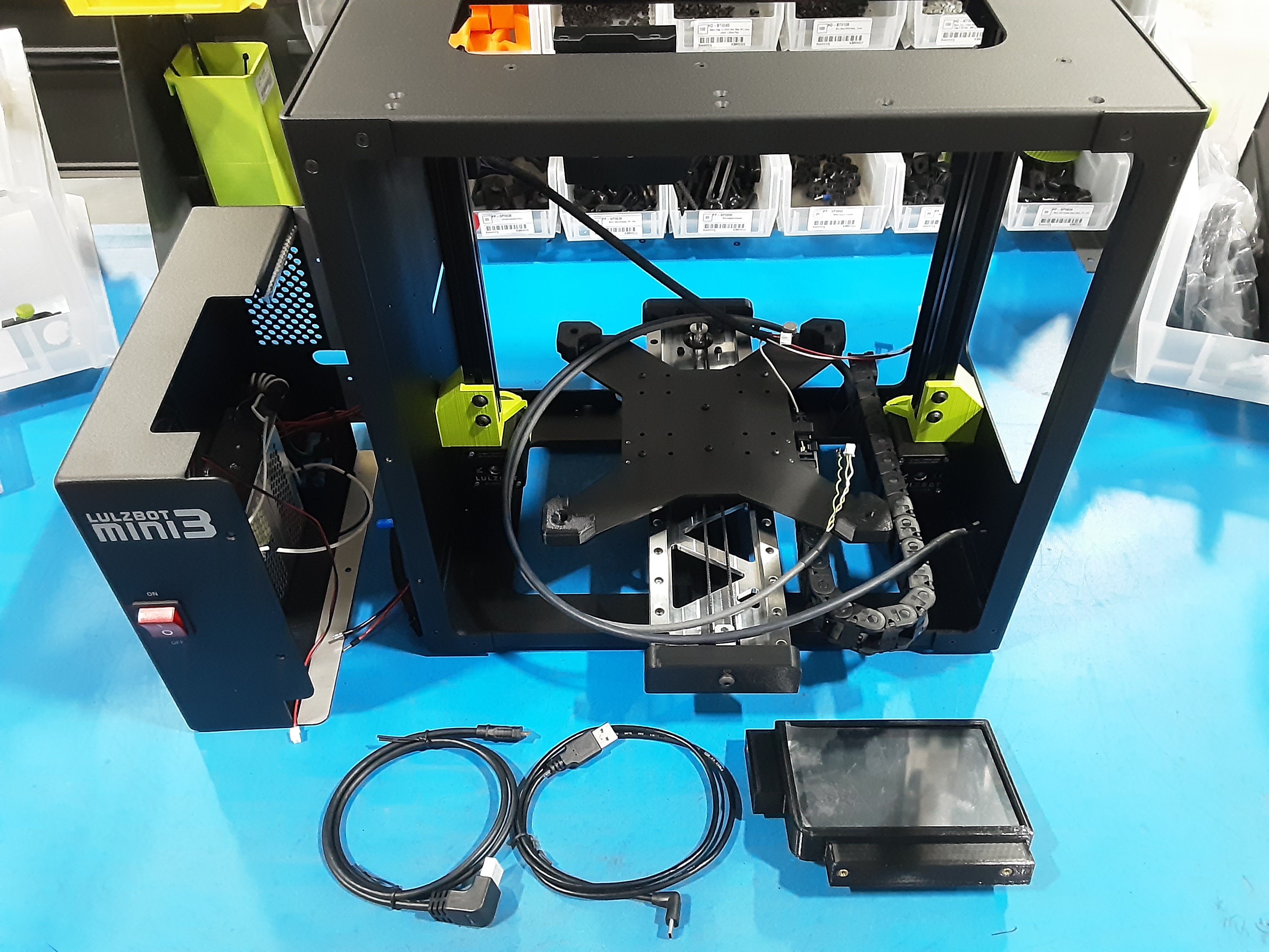
Screen Assembly (S.A.)
Board Attachment
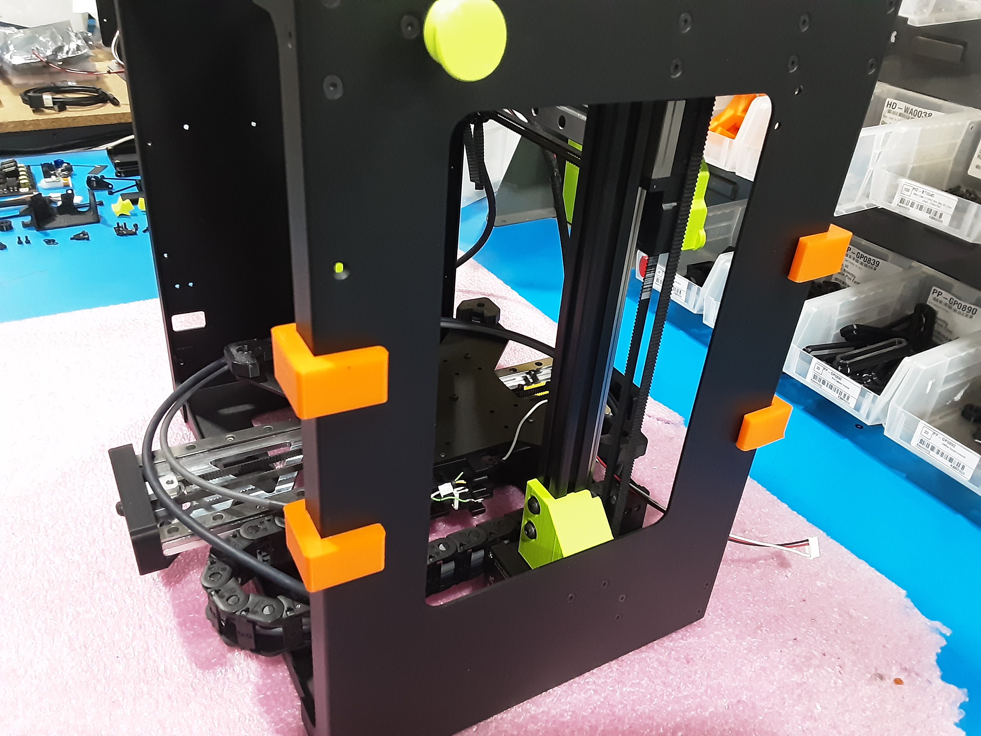
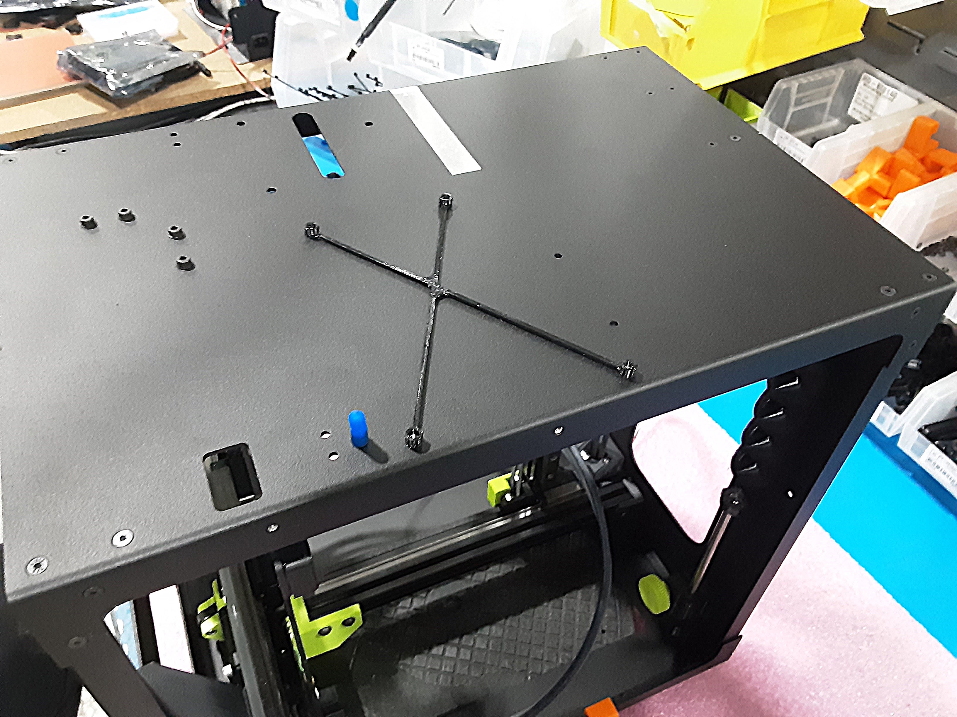
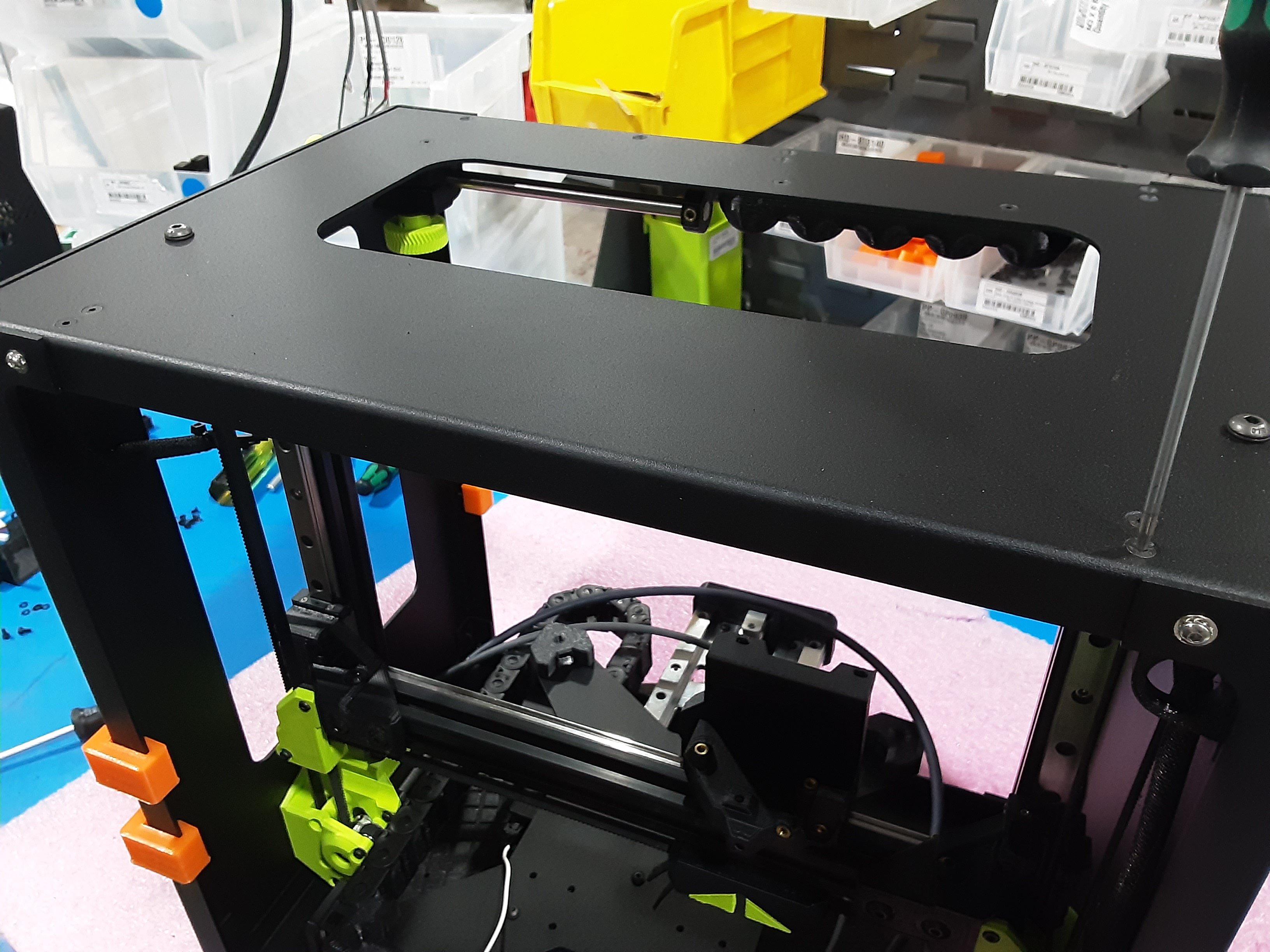
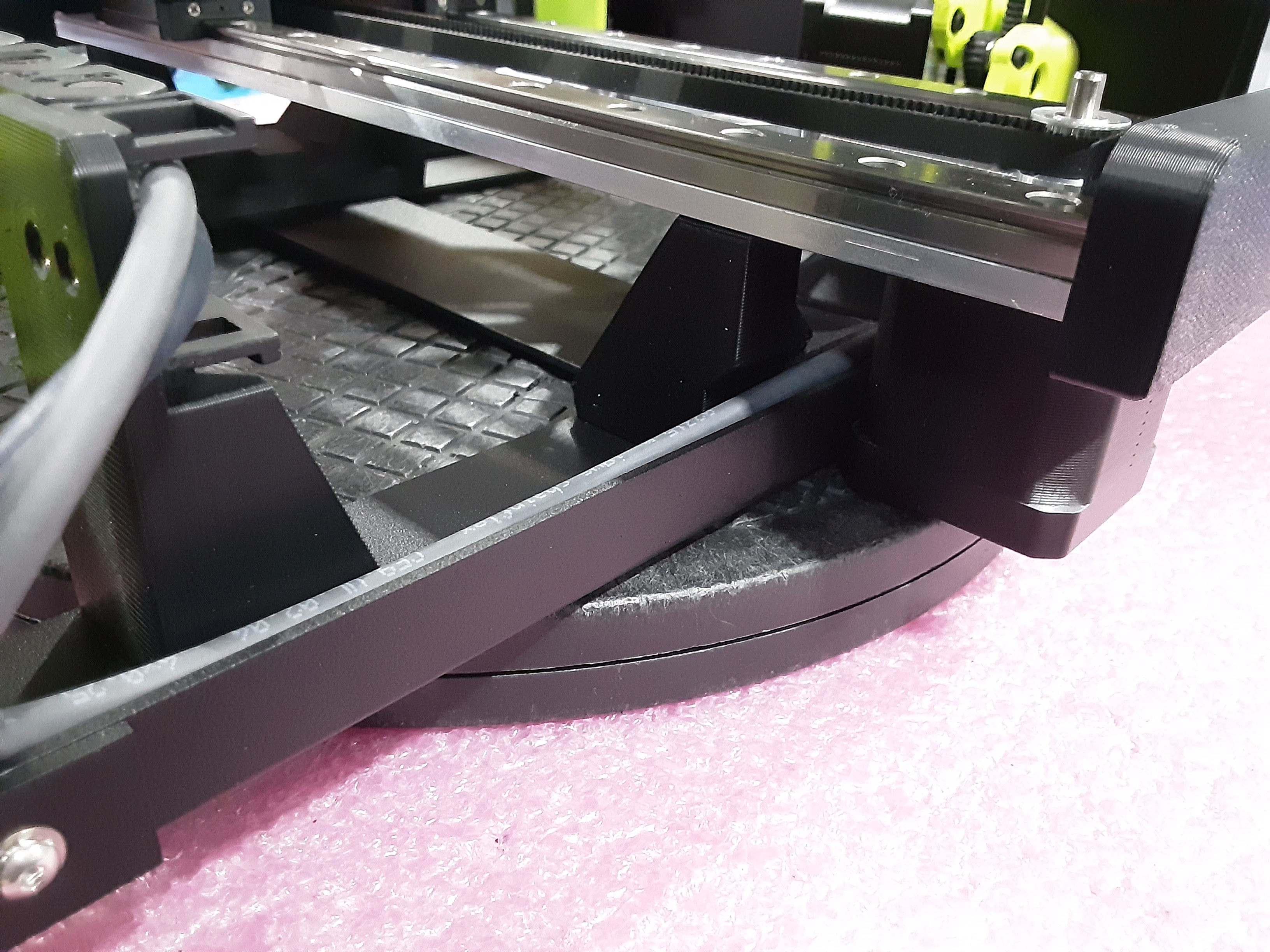
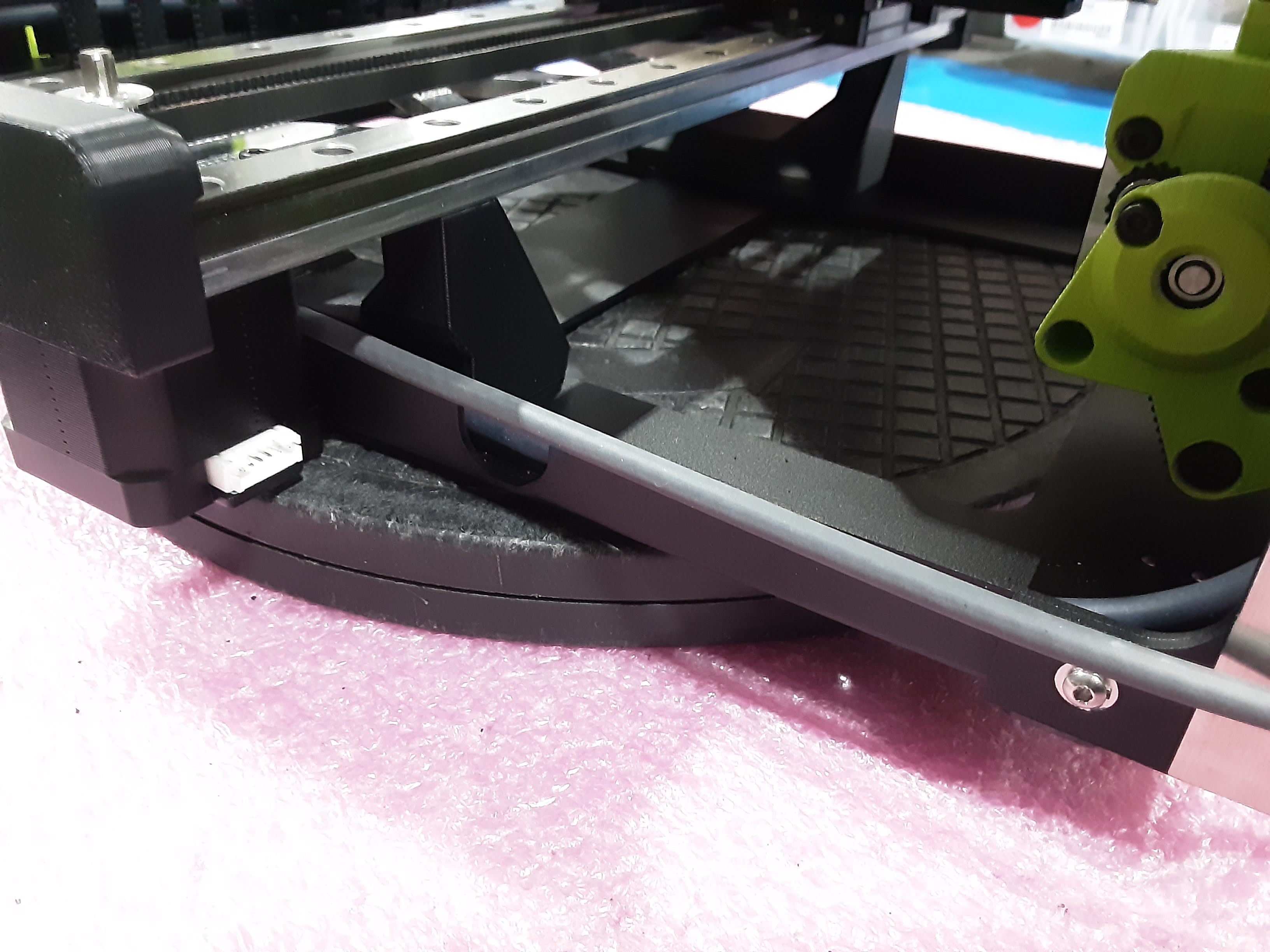
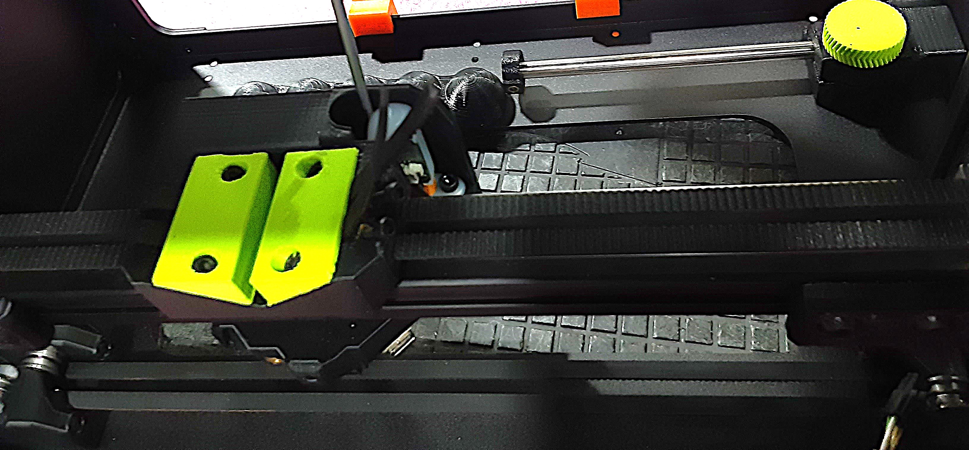
2A) Whenever rotating the F.A. be sure to use four orange spacer jigs on the side that will be on the table.
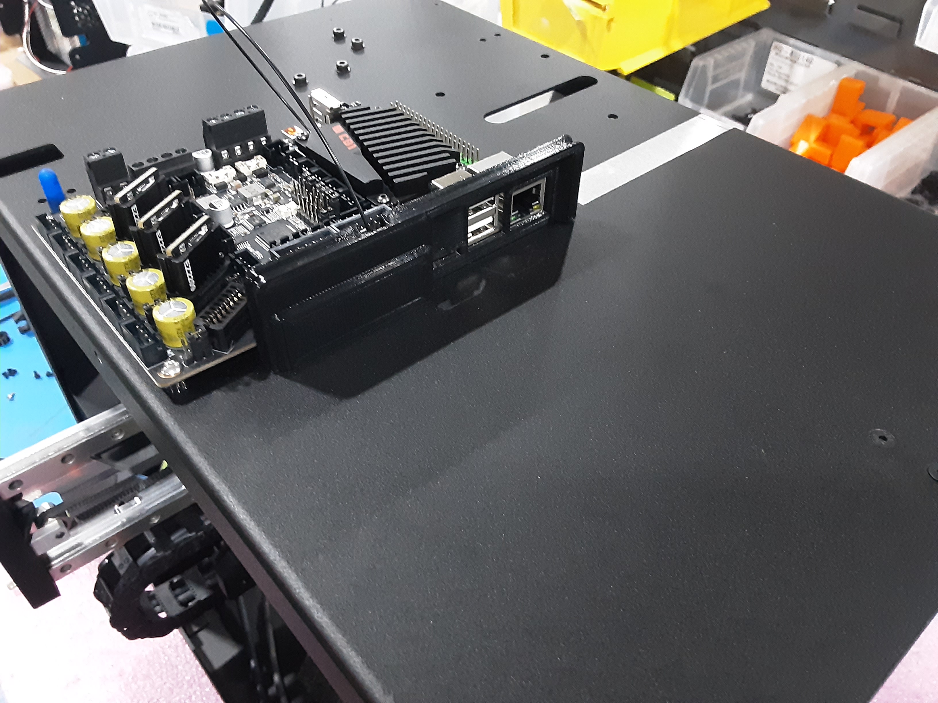
2B) Snap into place PP-GP0894 x1 on the F.A.
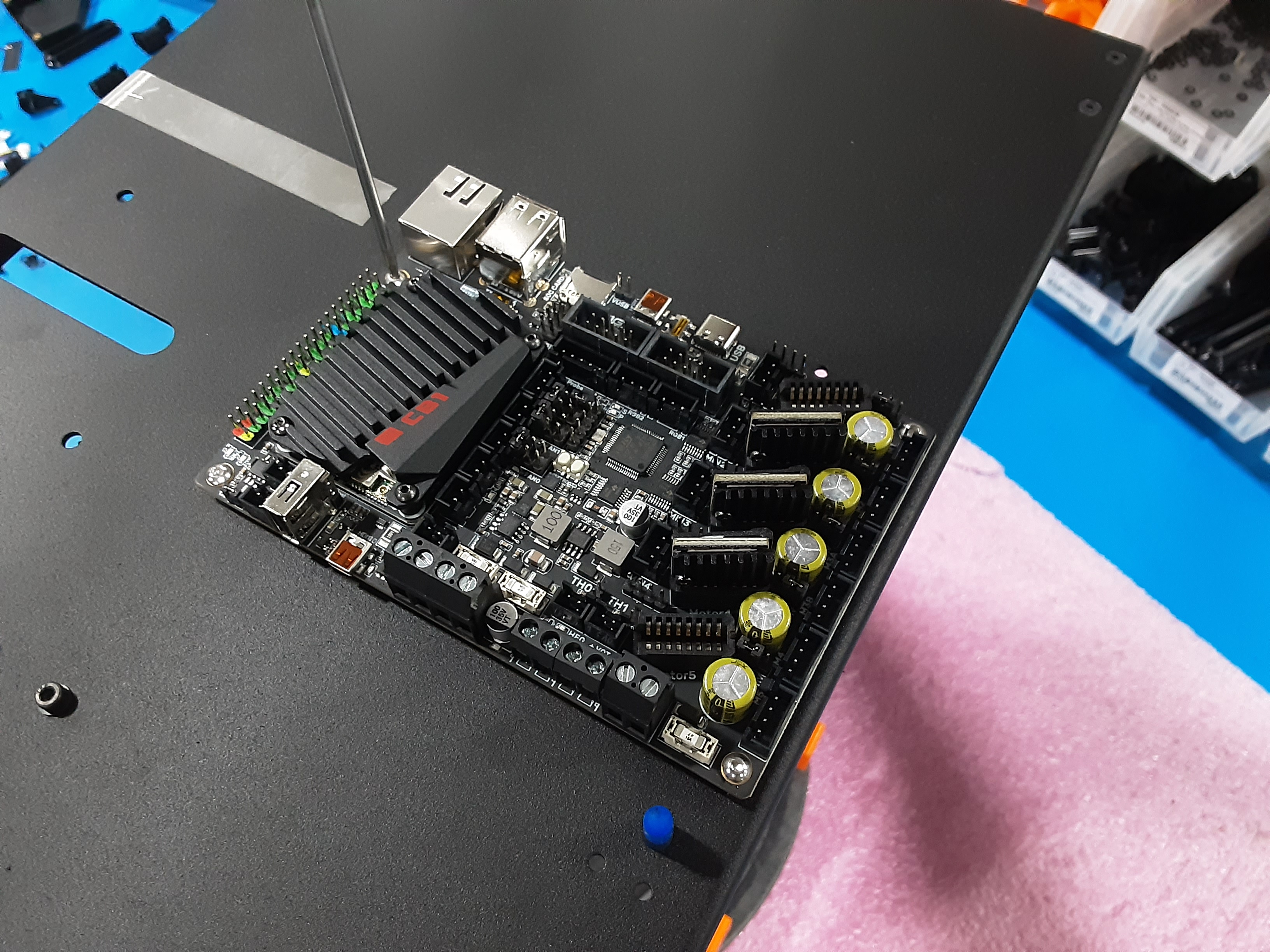
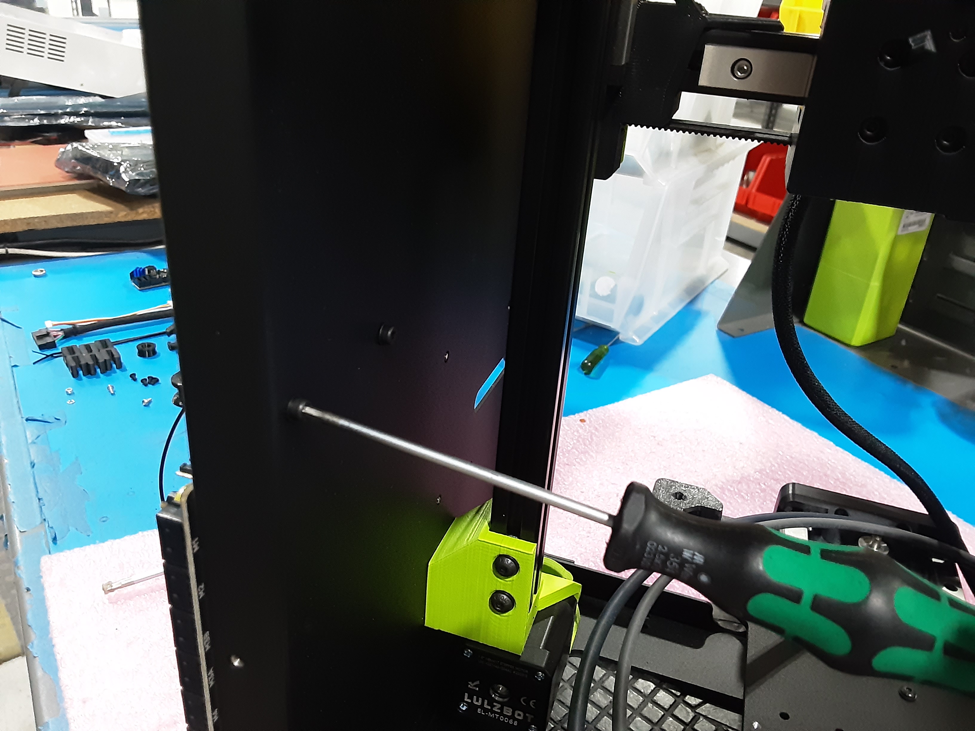
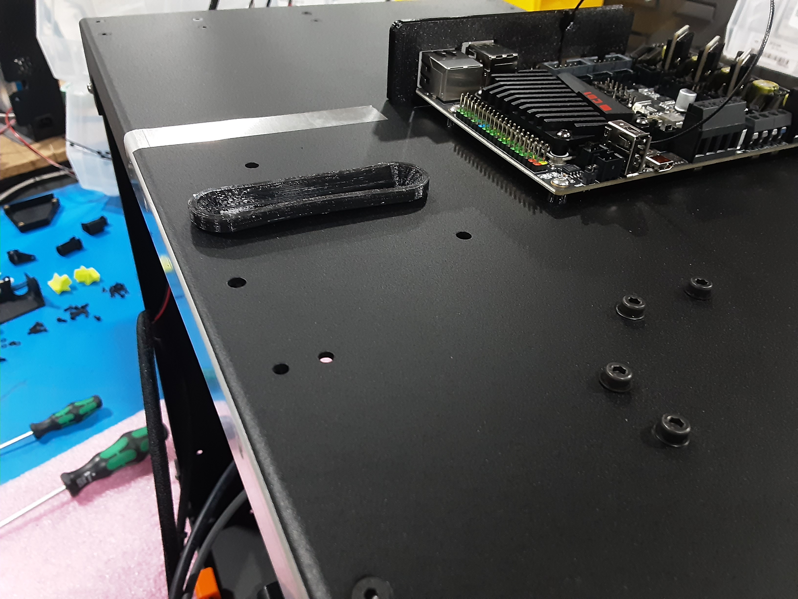
2C) Line up PC-BD0127 on top of PP-GP0894 and attach using HD-BT0104 x4.
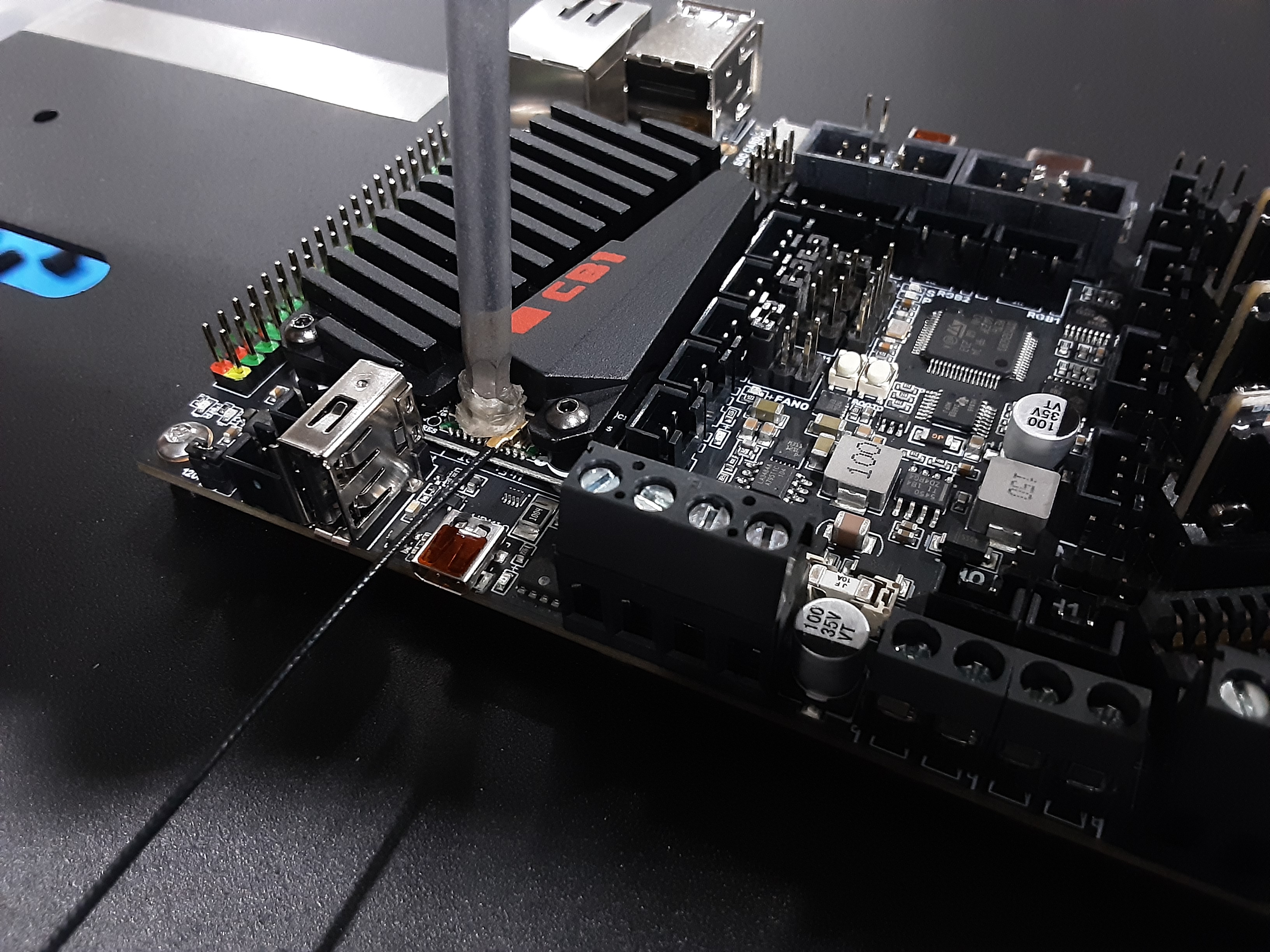
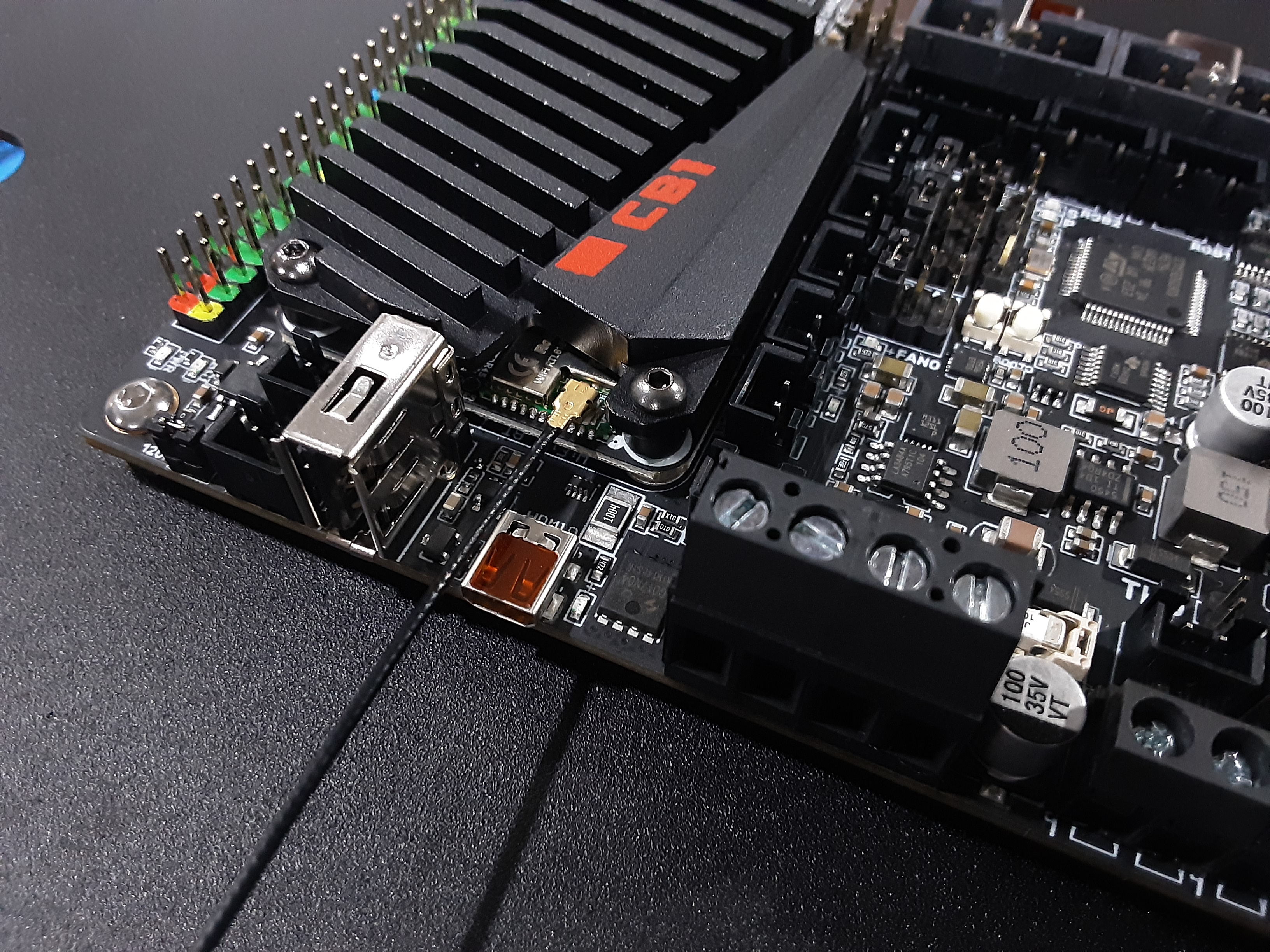
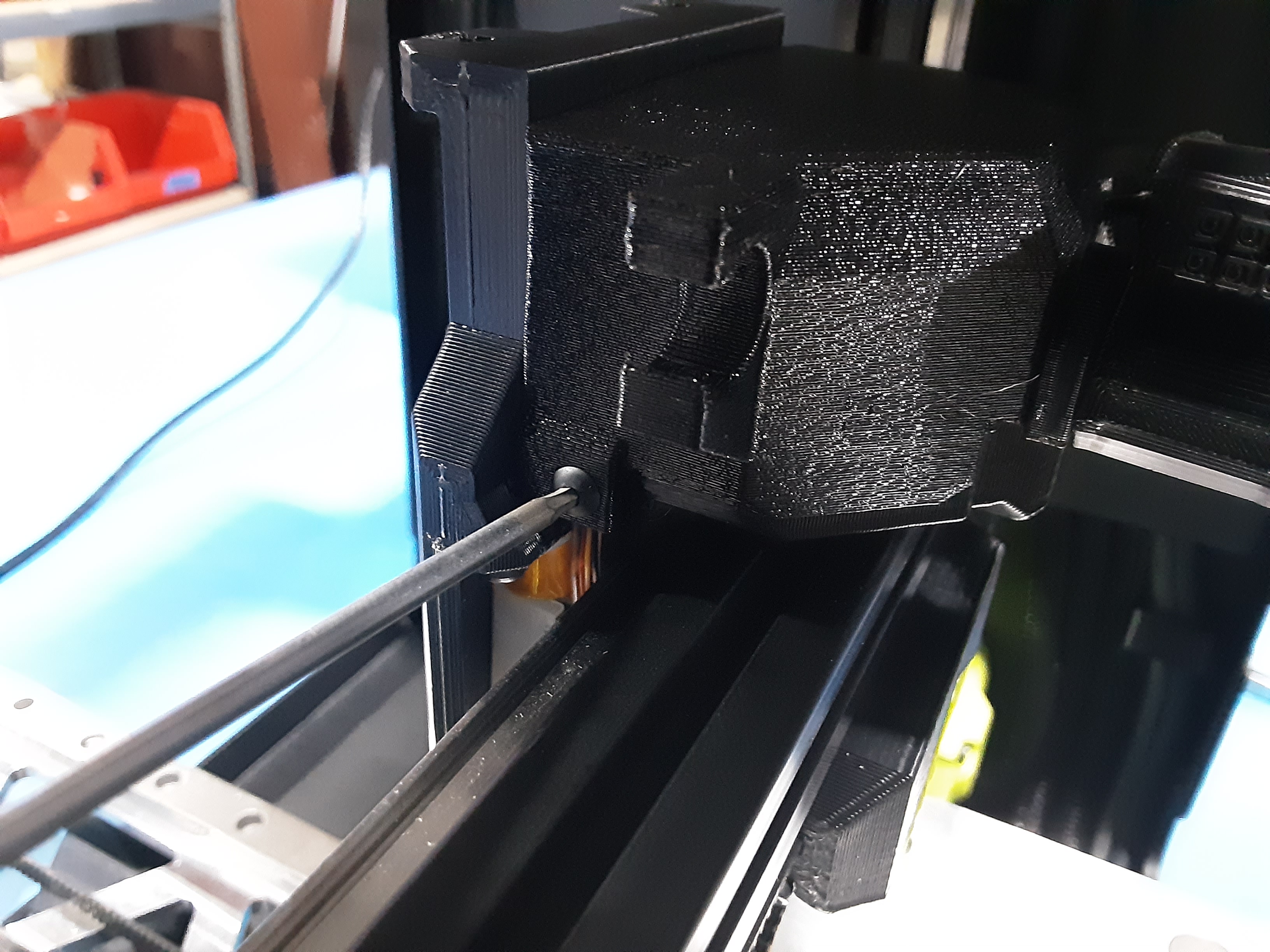
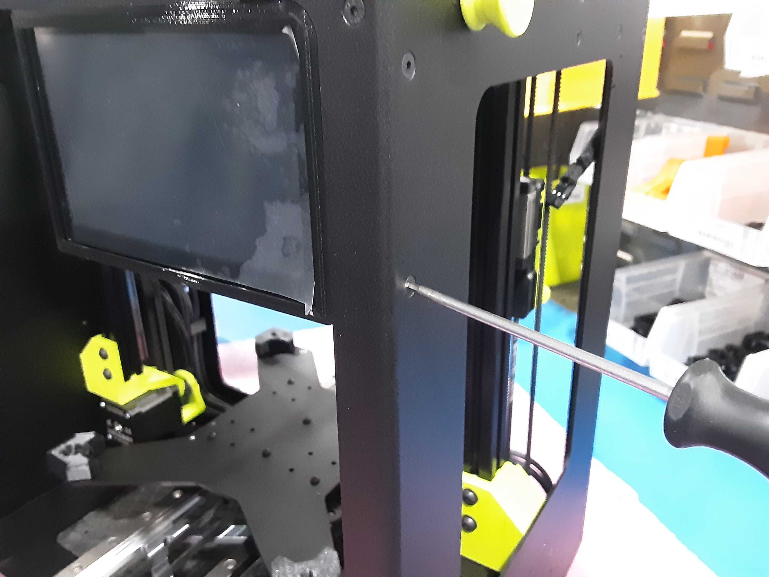
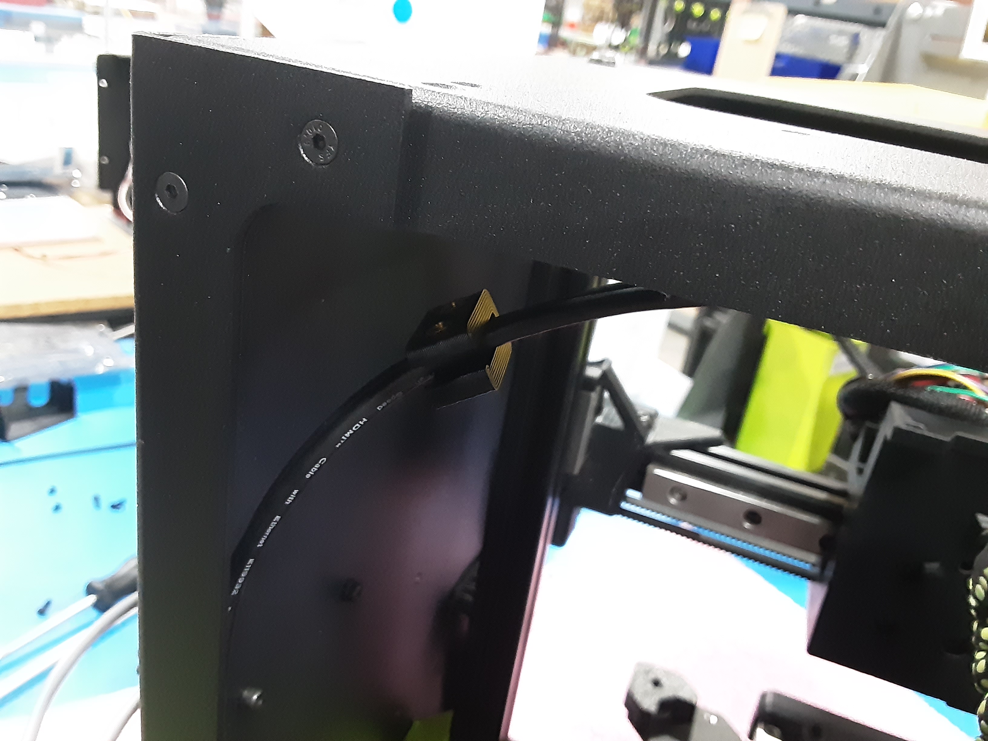
2D) Using the special screwdriver with a soft end, attach the Wi-Fi antenna that came with PC-BD0127 to the board.
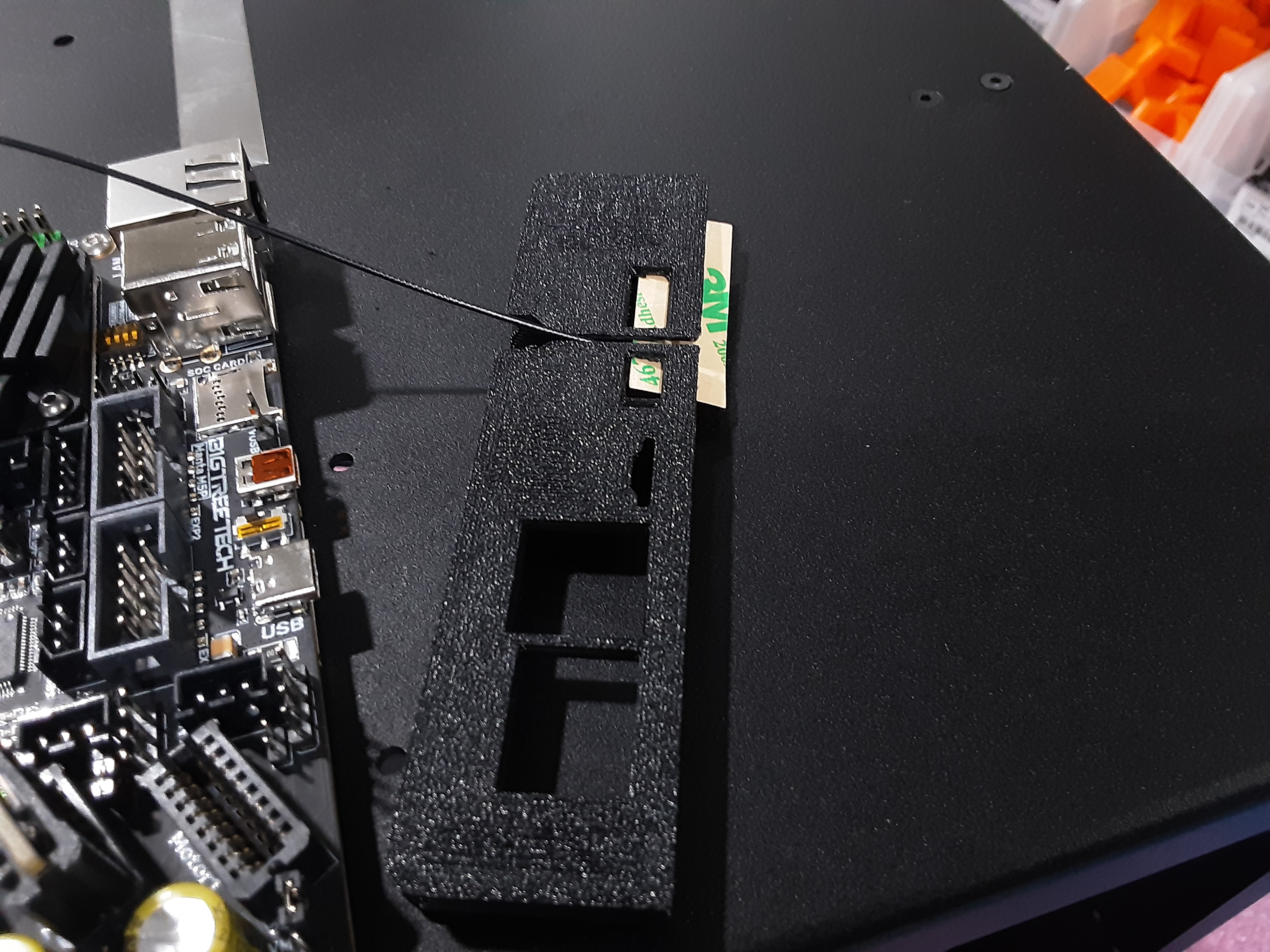
2E) Slide the Wi-Fi antenna into PP-GP0884 in shown orientation.
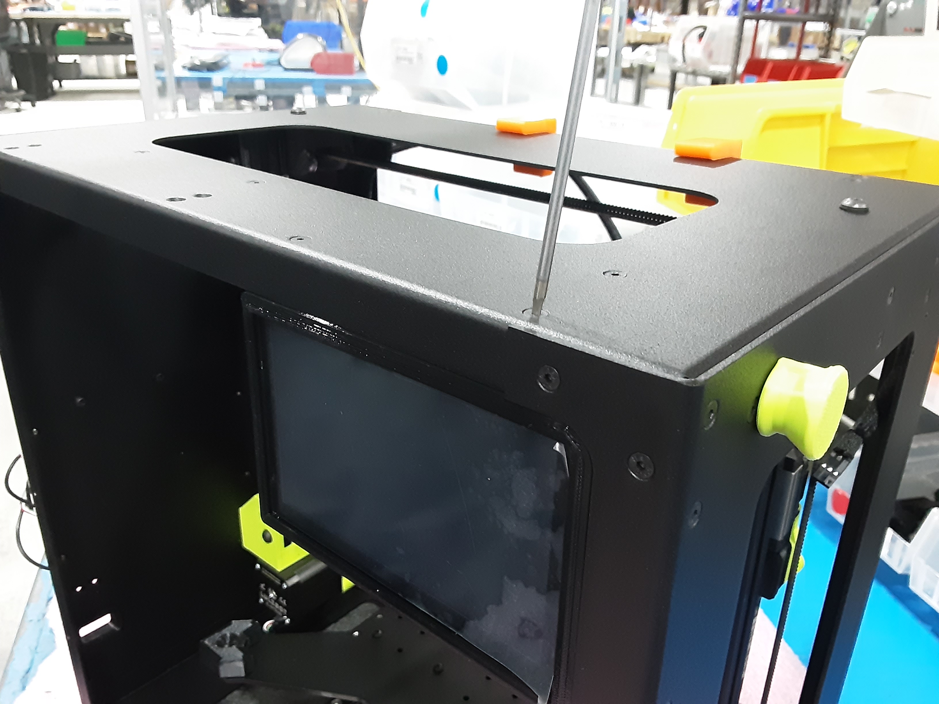
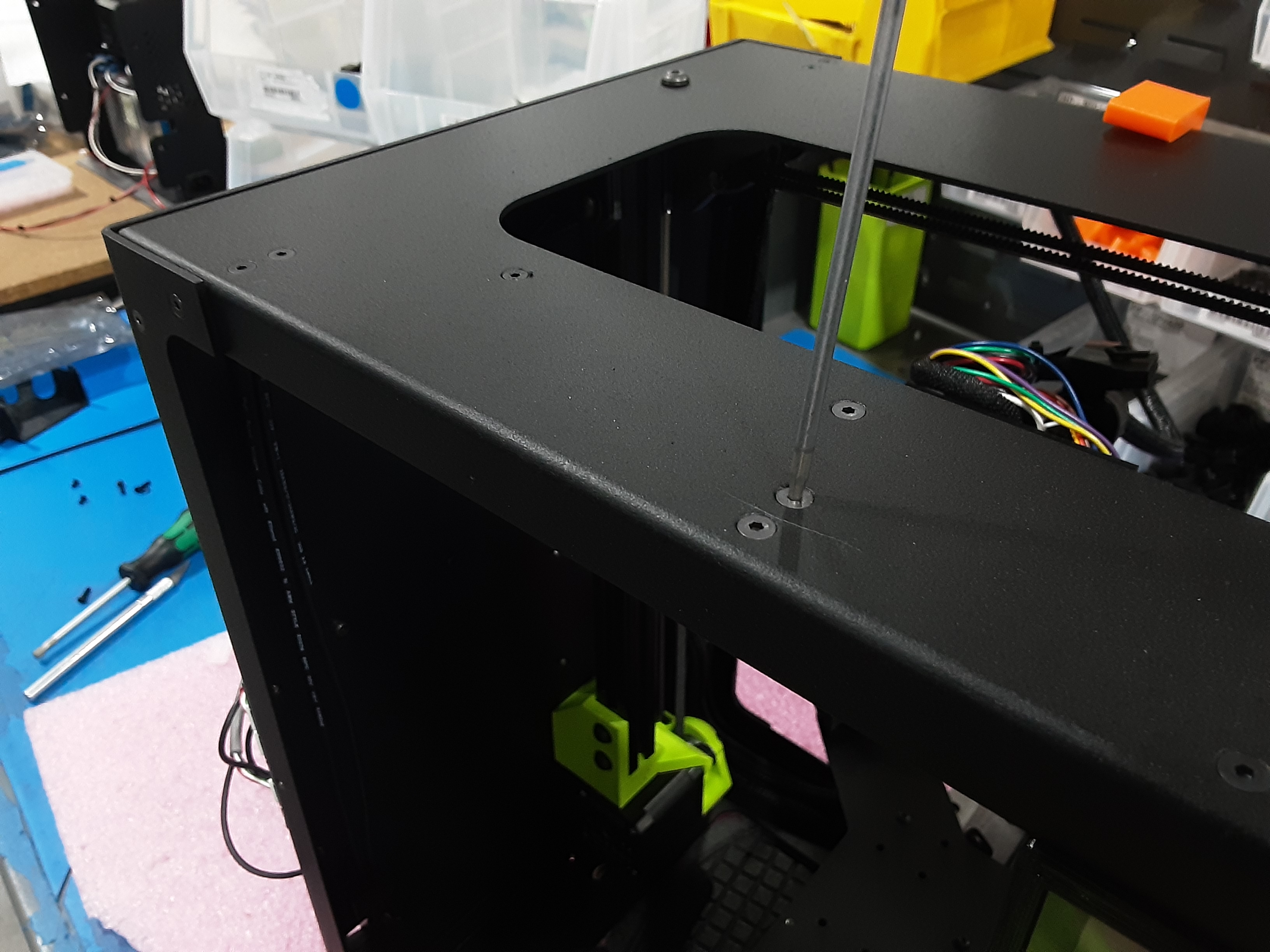
2F) Attach PP-GP0884 to F.A. using HD-BT0157 x2 and HD-WA0038 x2.
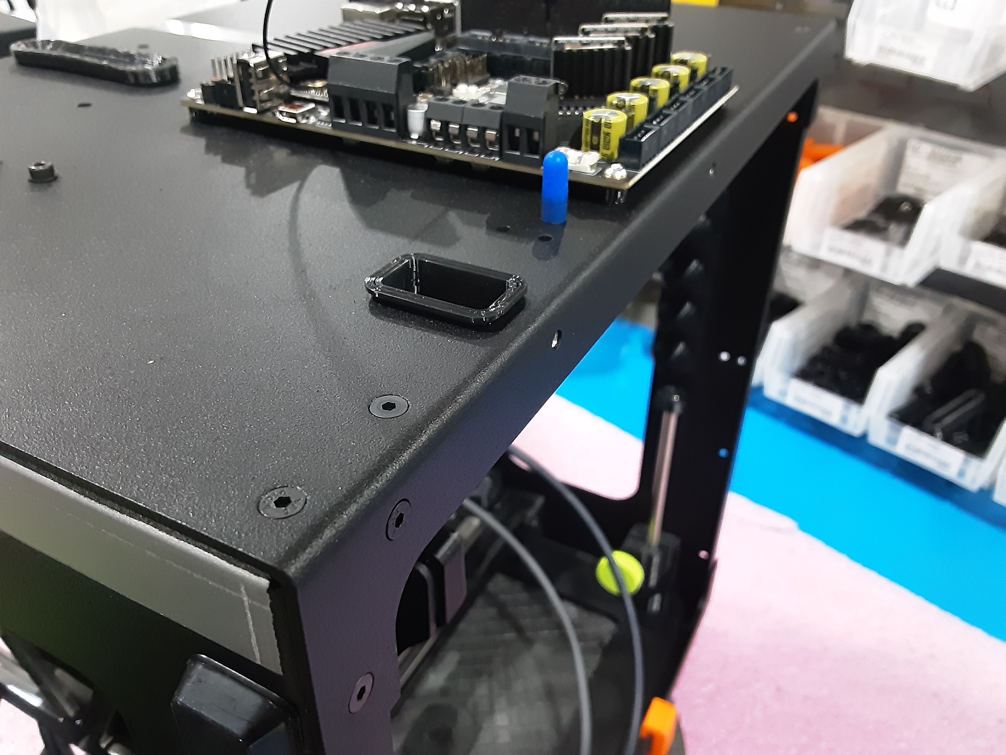
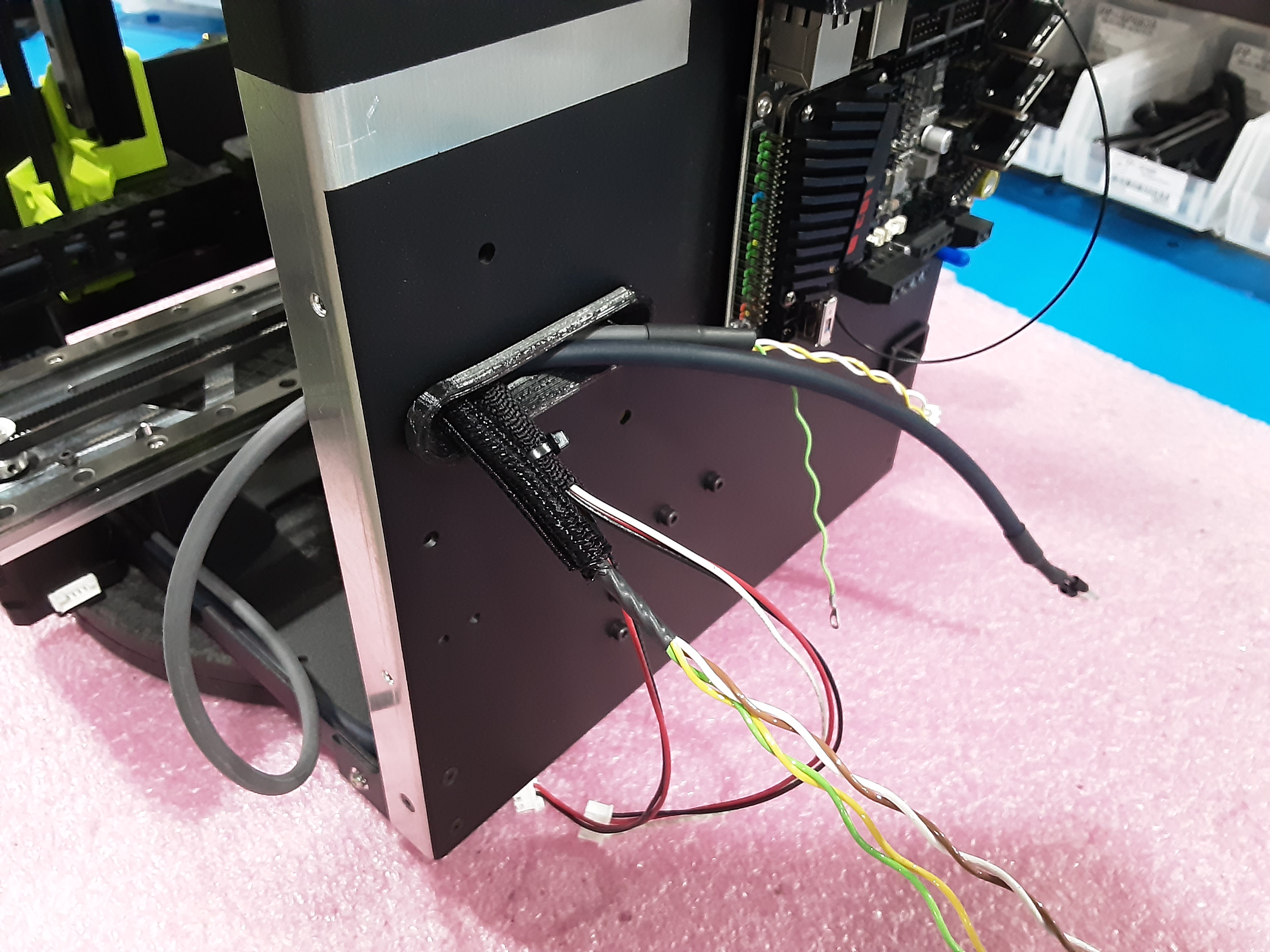
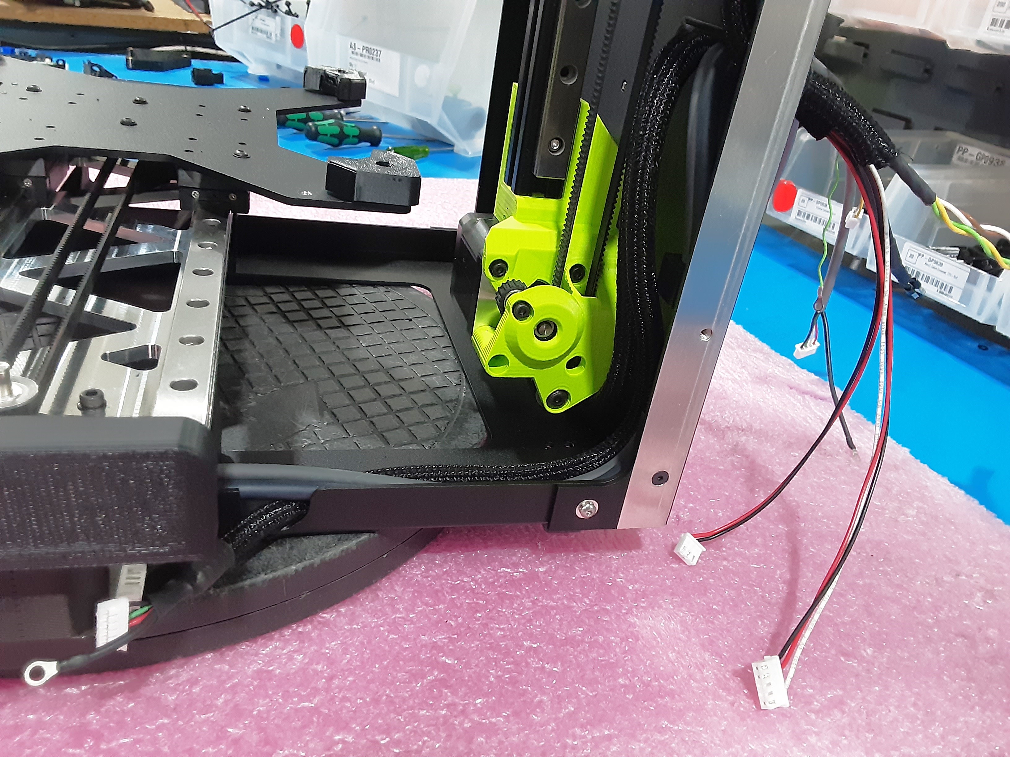
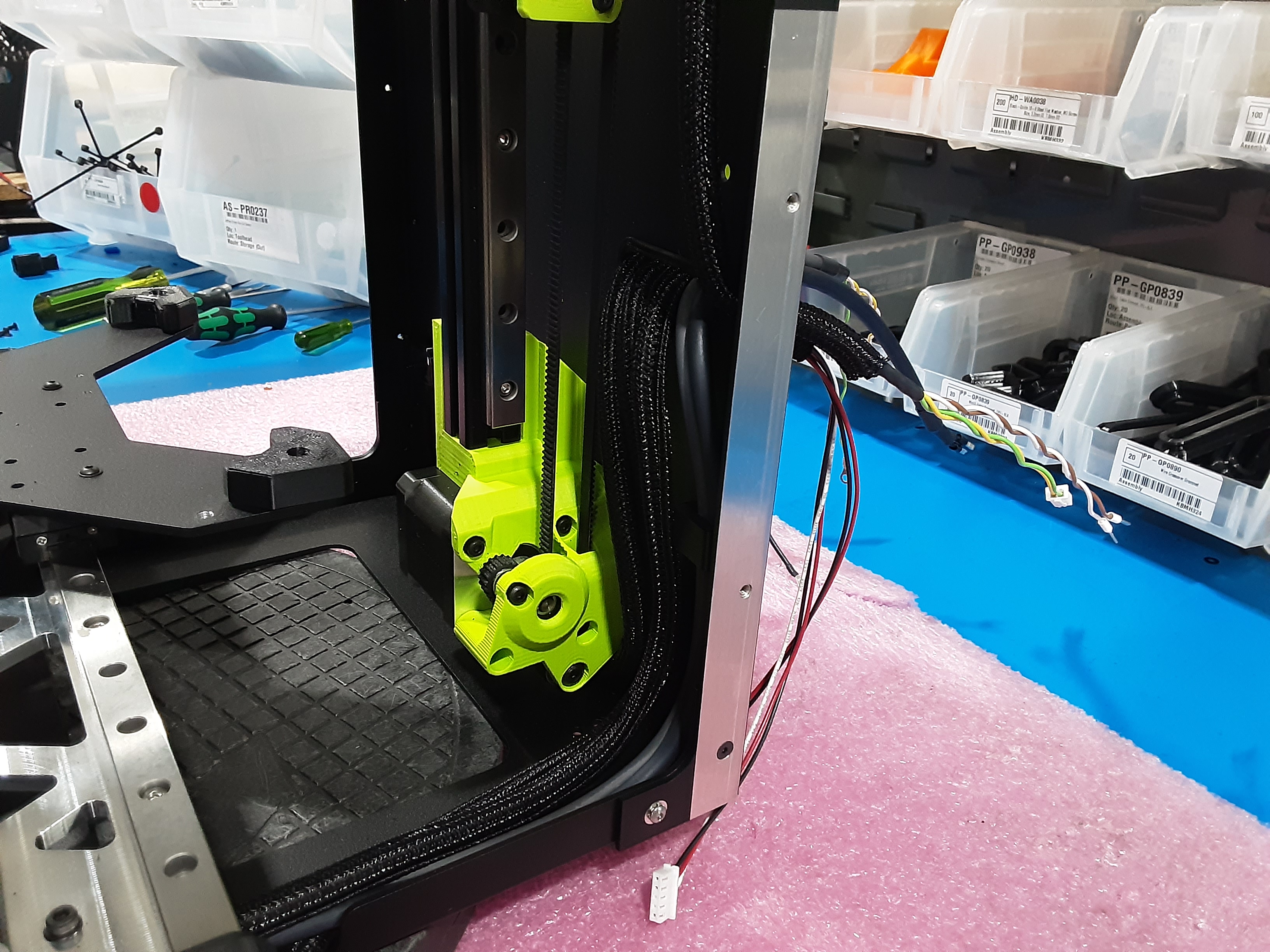
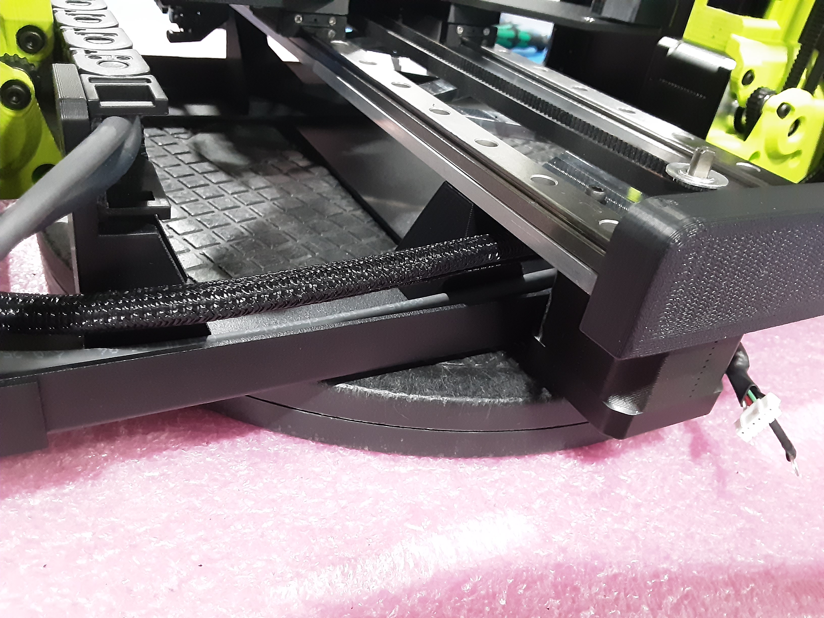
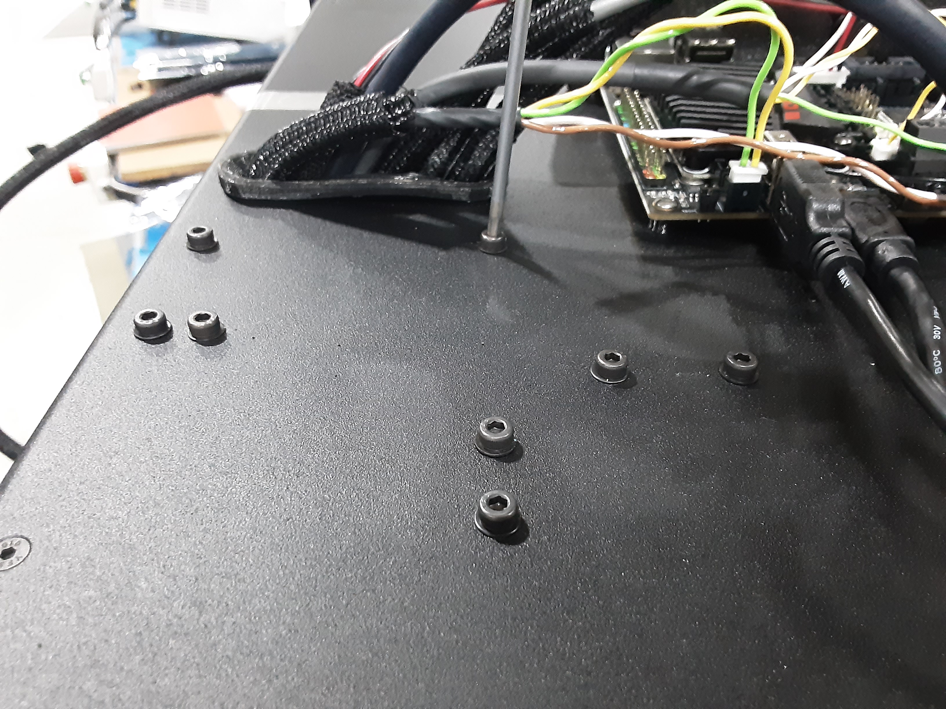
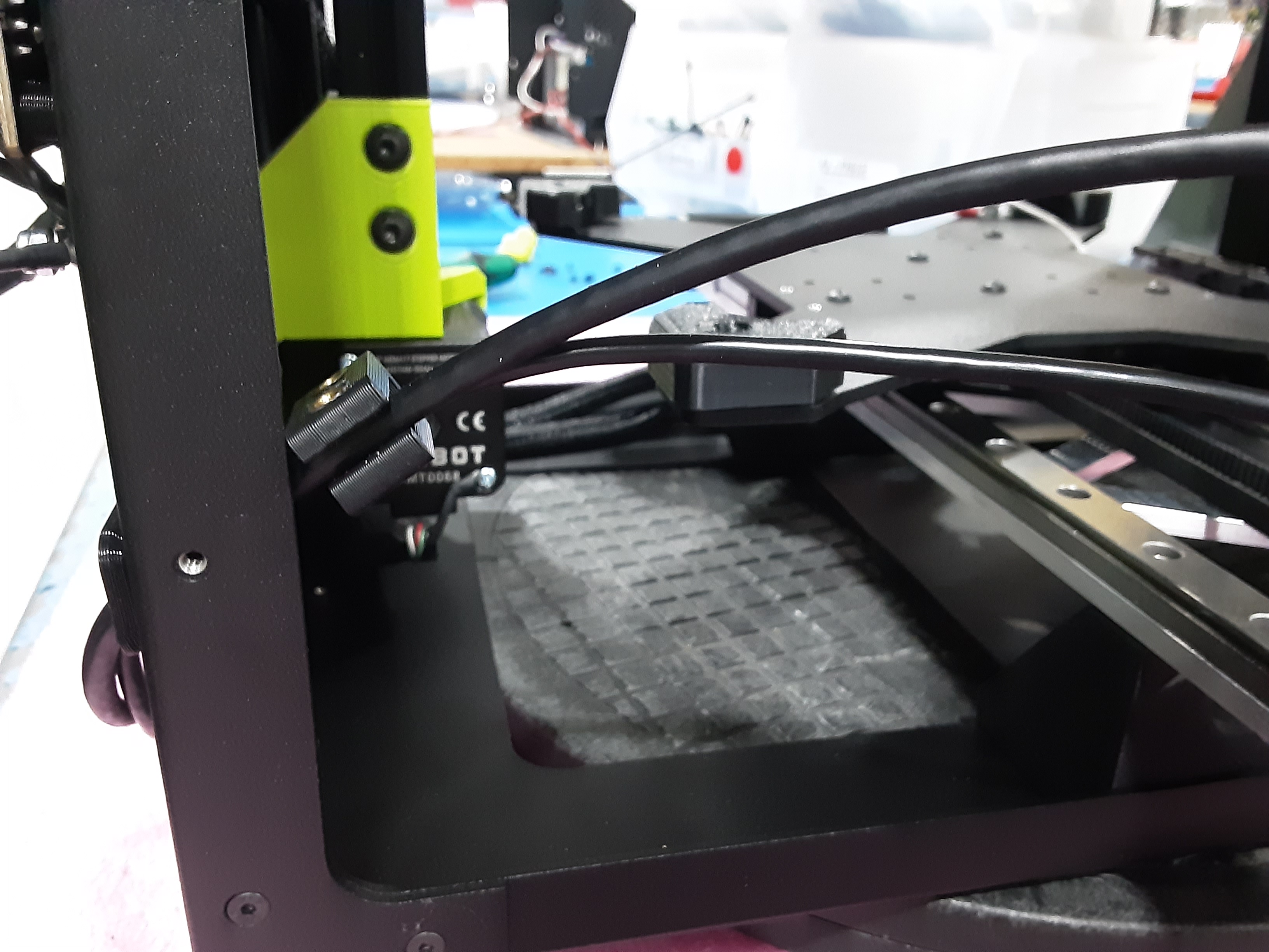
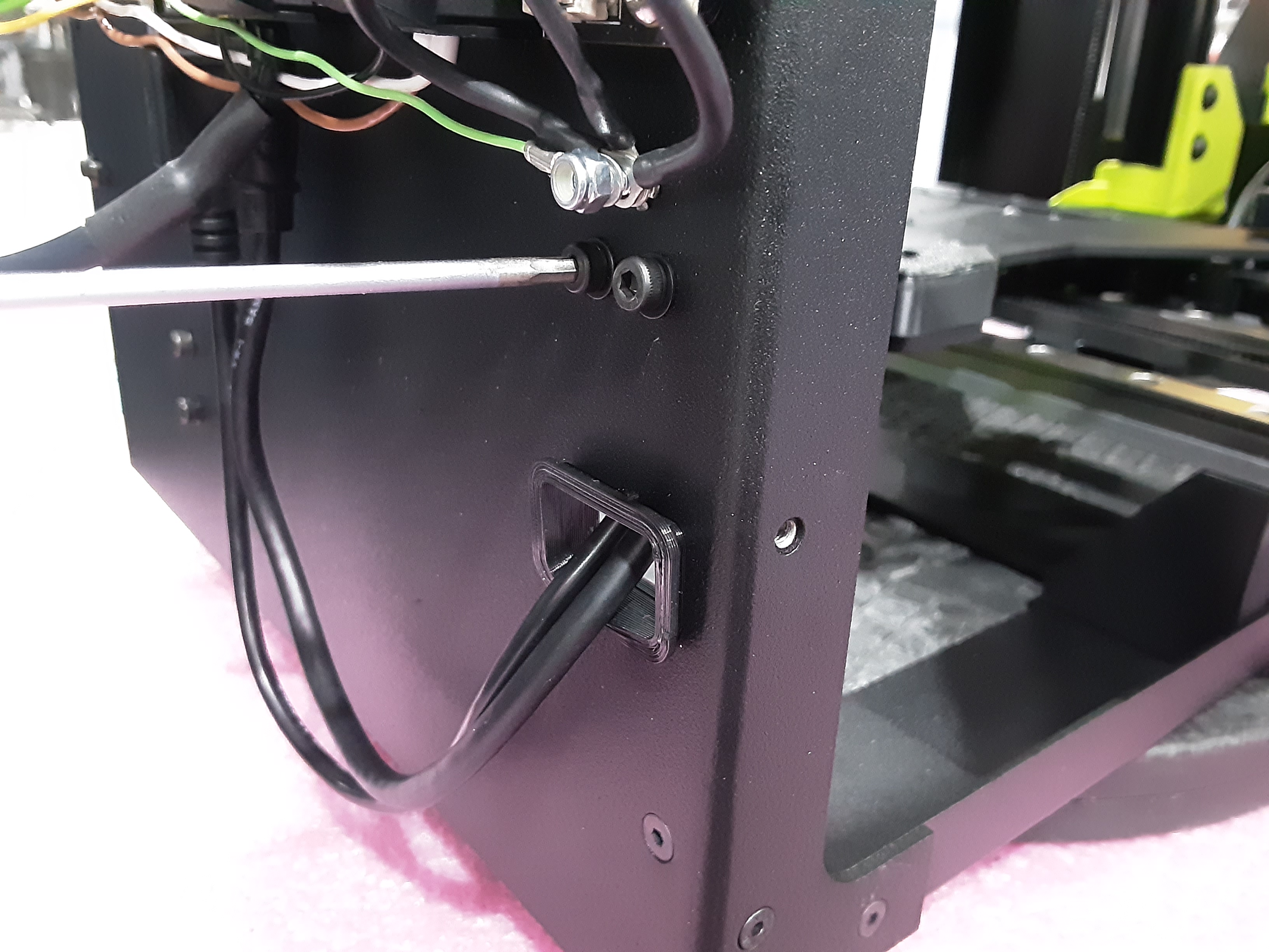
2G) Install PP-GP0890 and PP-GP0839 into the F.A. as shown.
Wire Routing
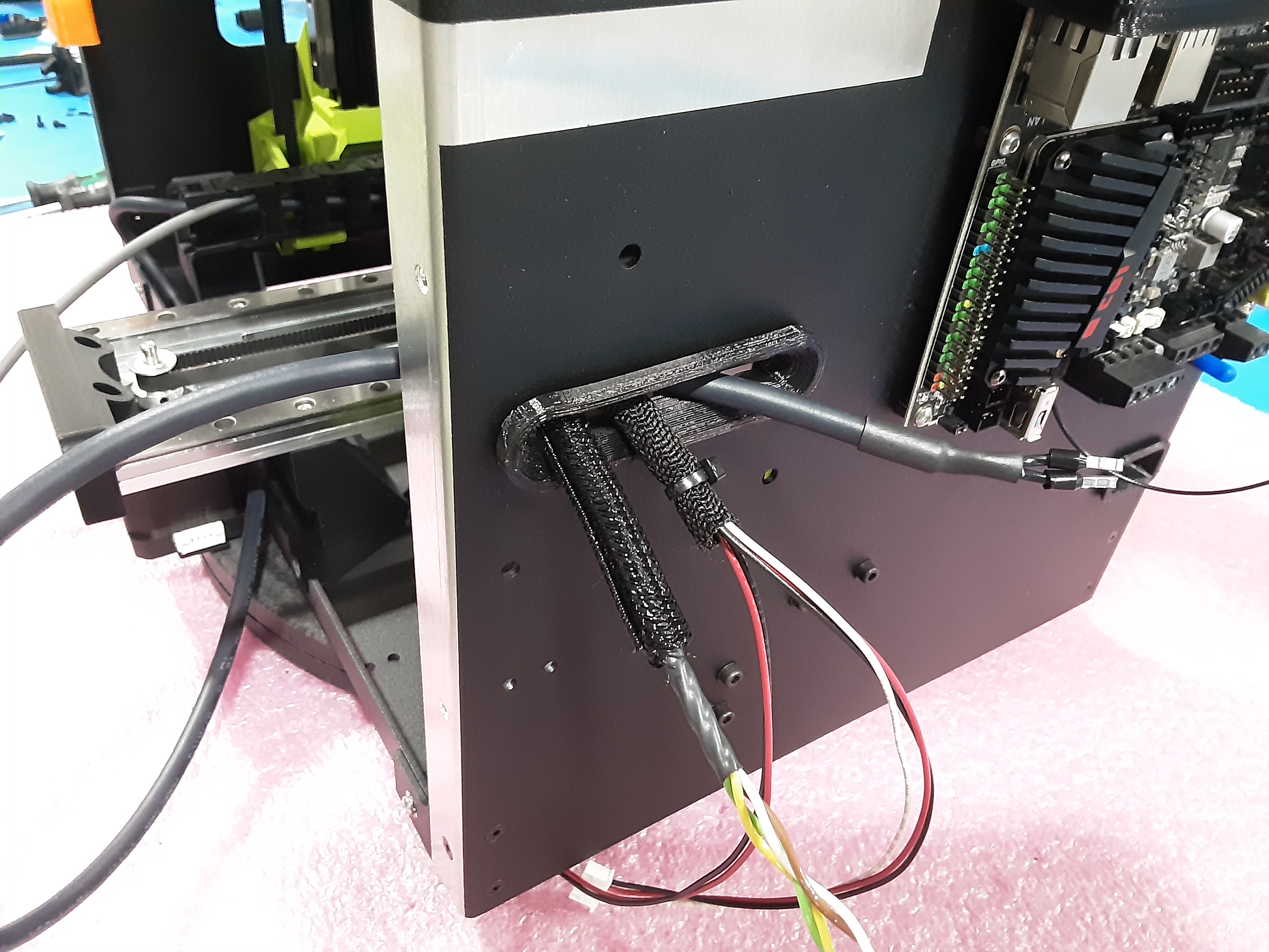
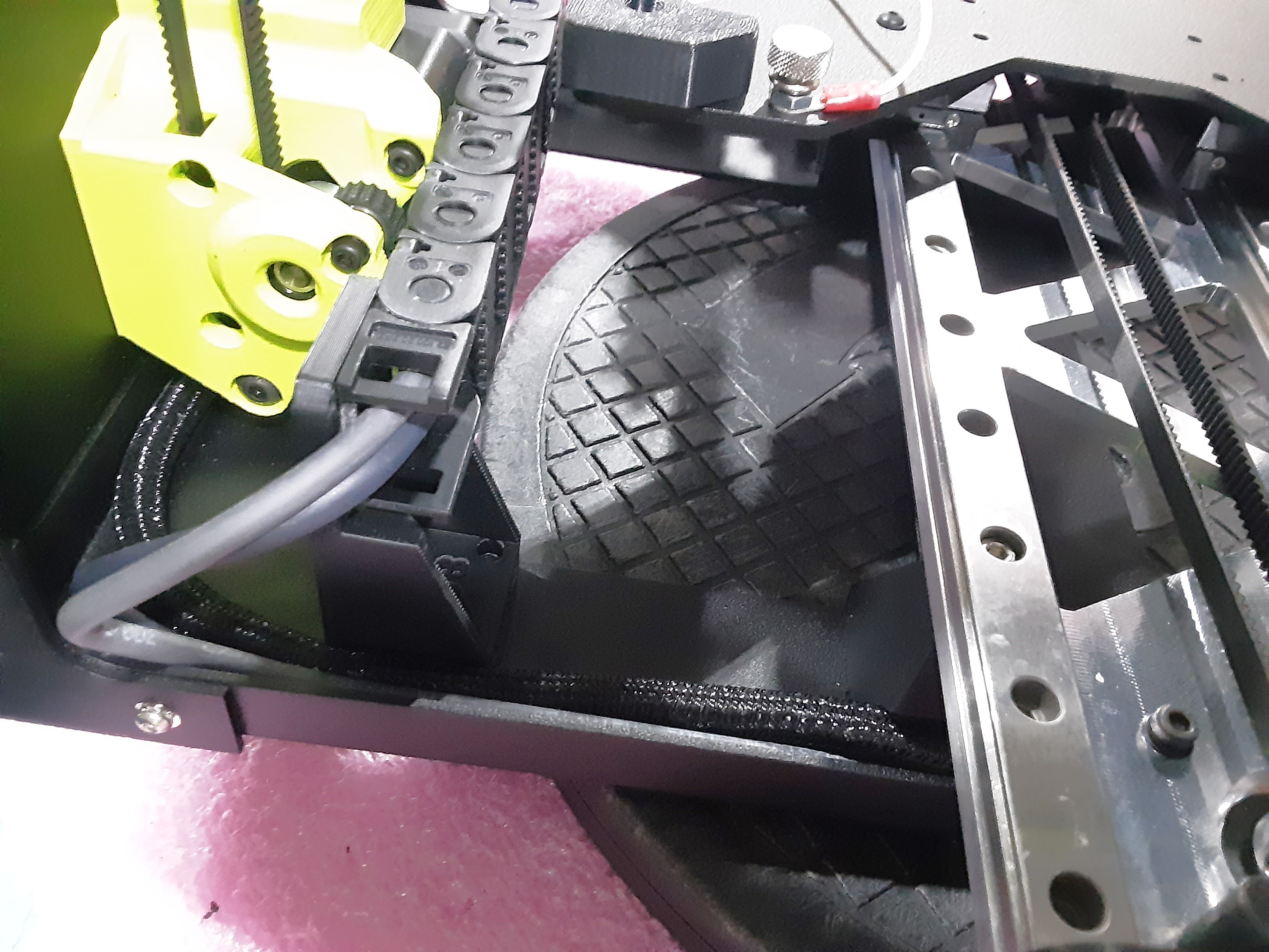
3A) Take EL-HR0214 from Z.L.L. and route the side of the wire with two plugs through PP-GP0890.
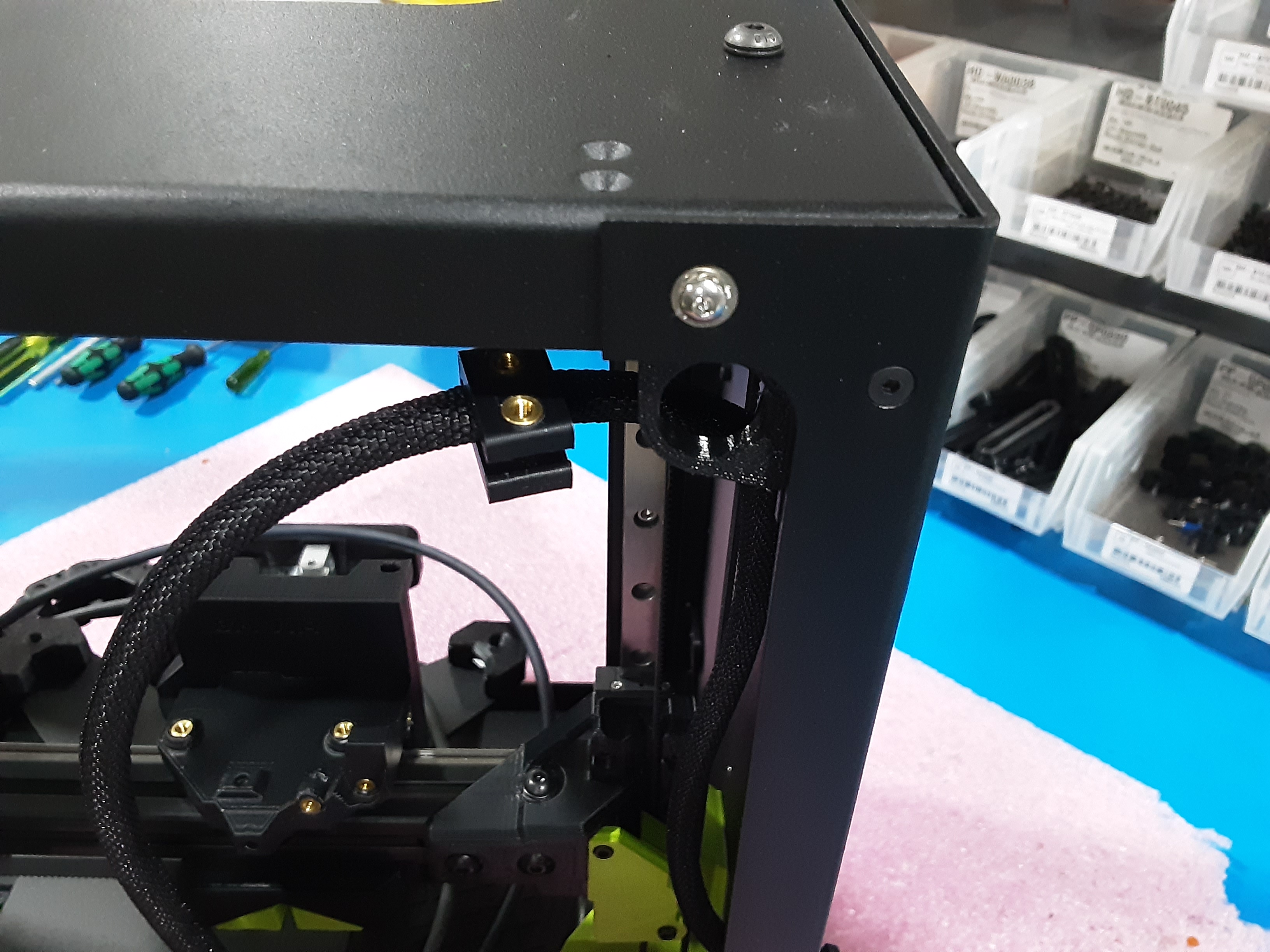
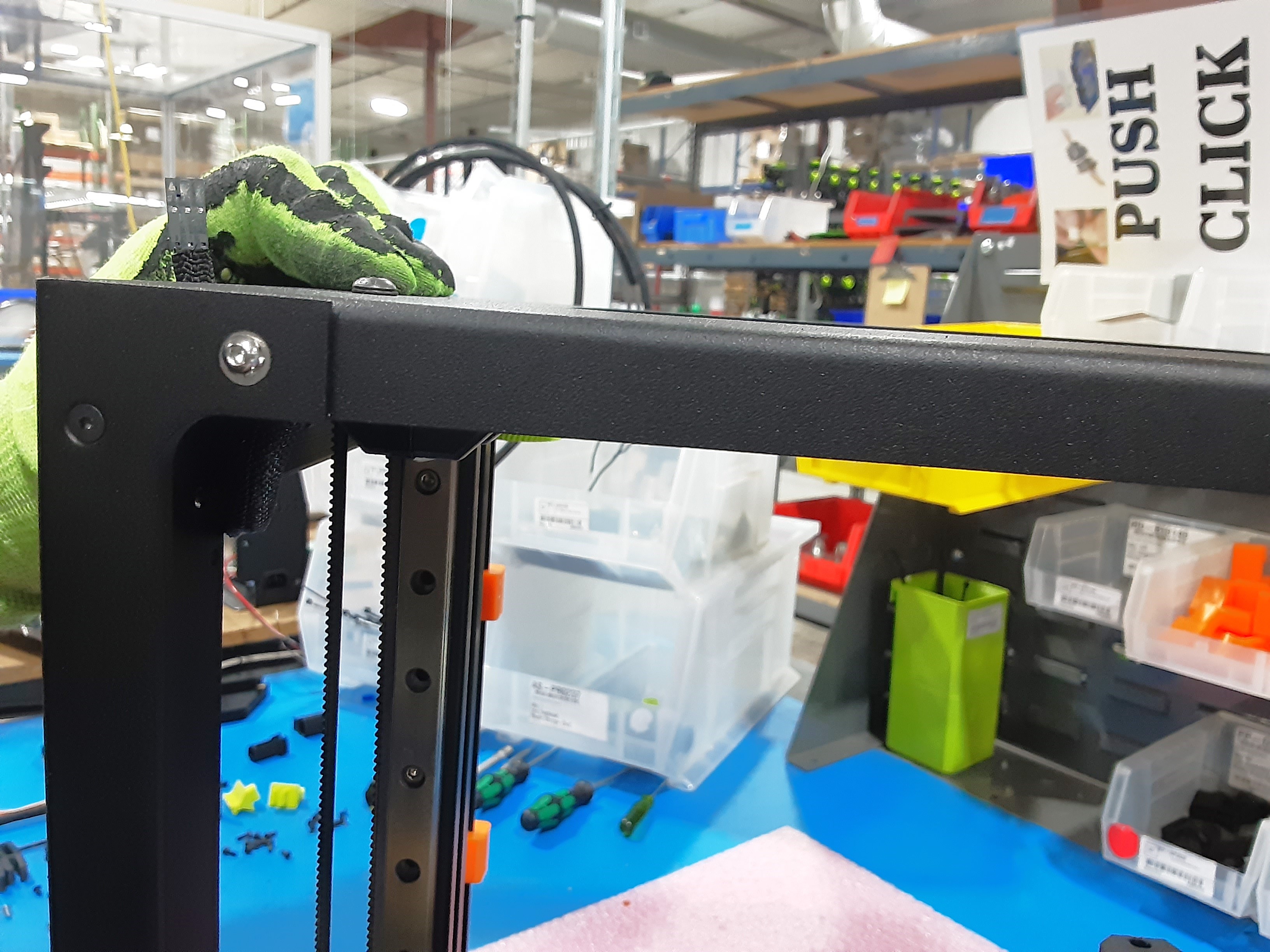
3B) Slide PP-GP0833 x2 over EL-HR0214 and with the opening of the “U” shape facing the back of the frame loosely attach using HD-BT0128 x4.
3C) Route EL-HR0214 as shown to ensure the plug reaches above the F.A.
3D) Tighten the HD-BT0128 x4 in PP-GP0833 x2.
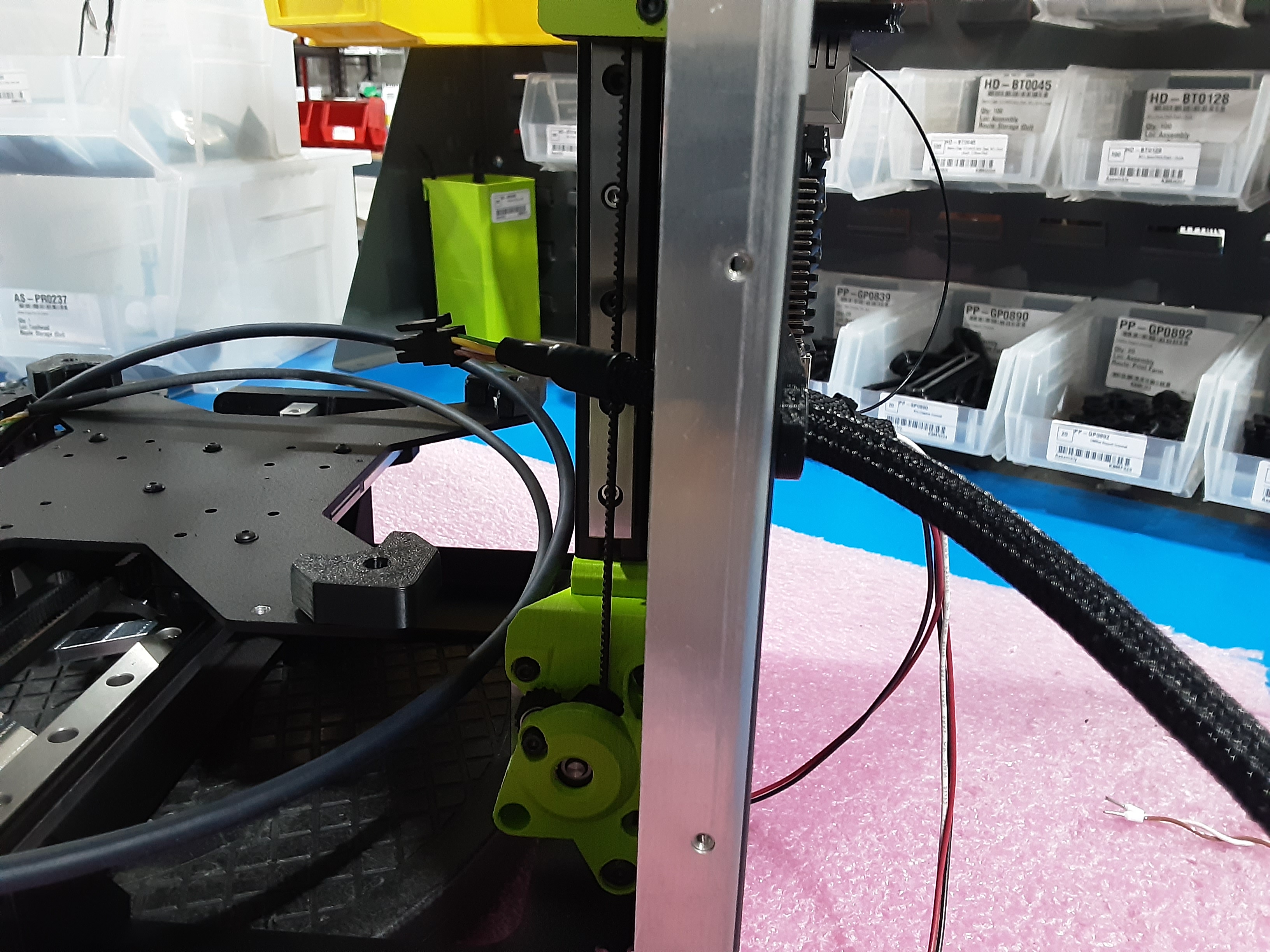
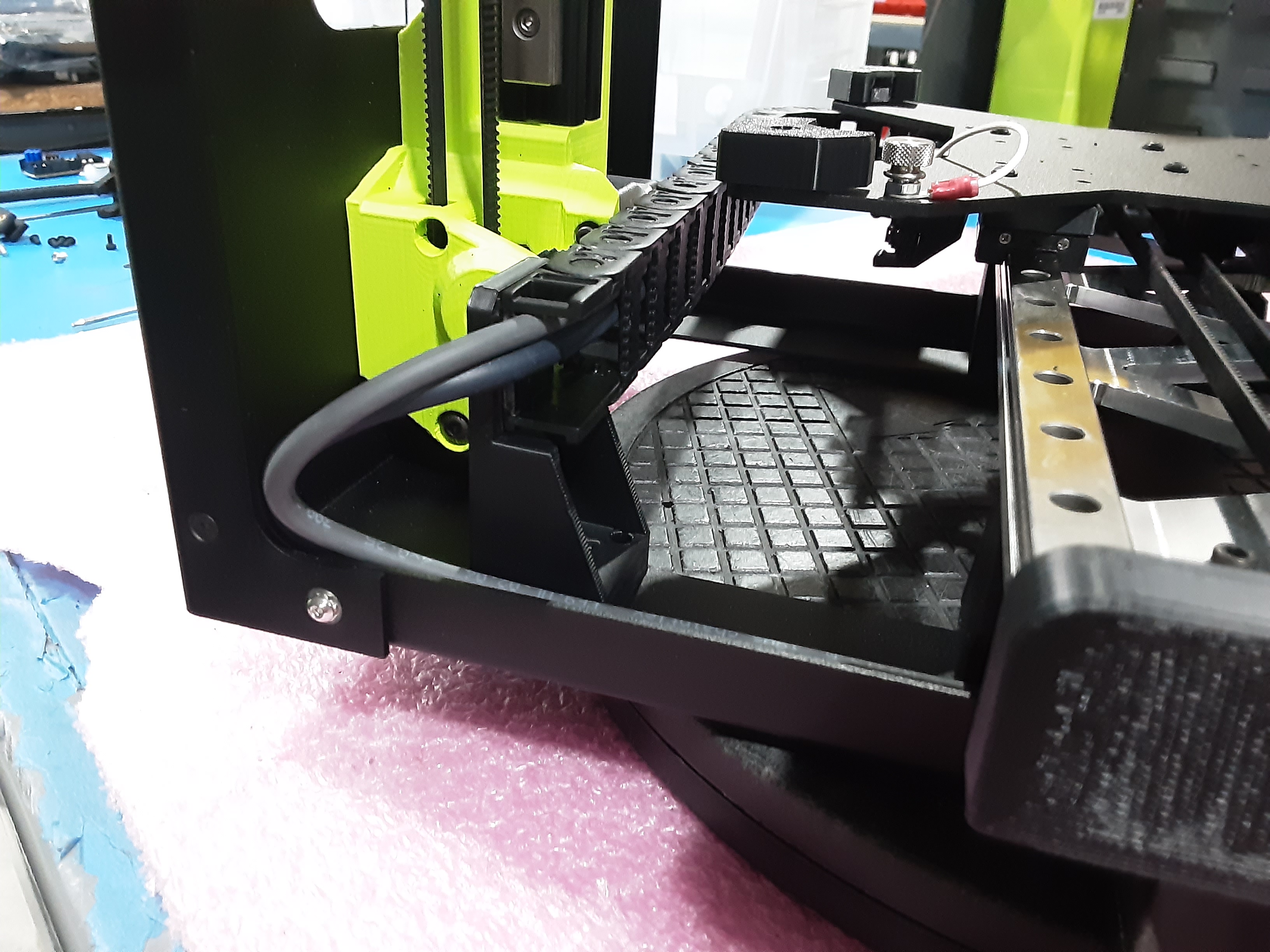
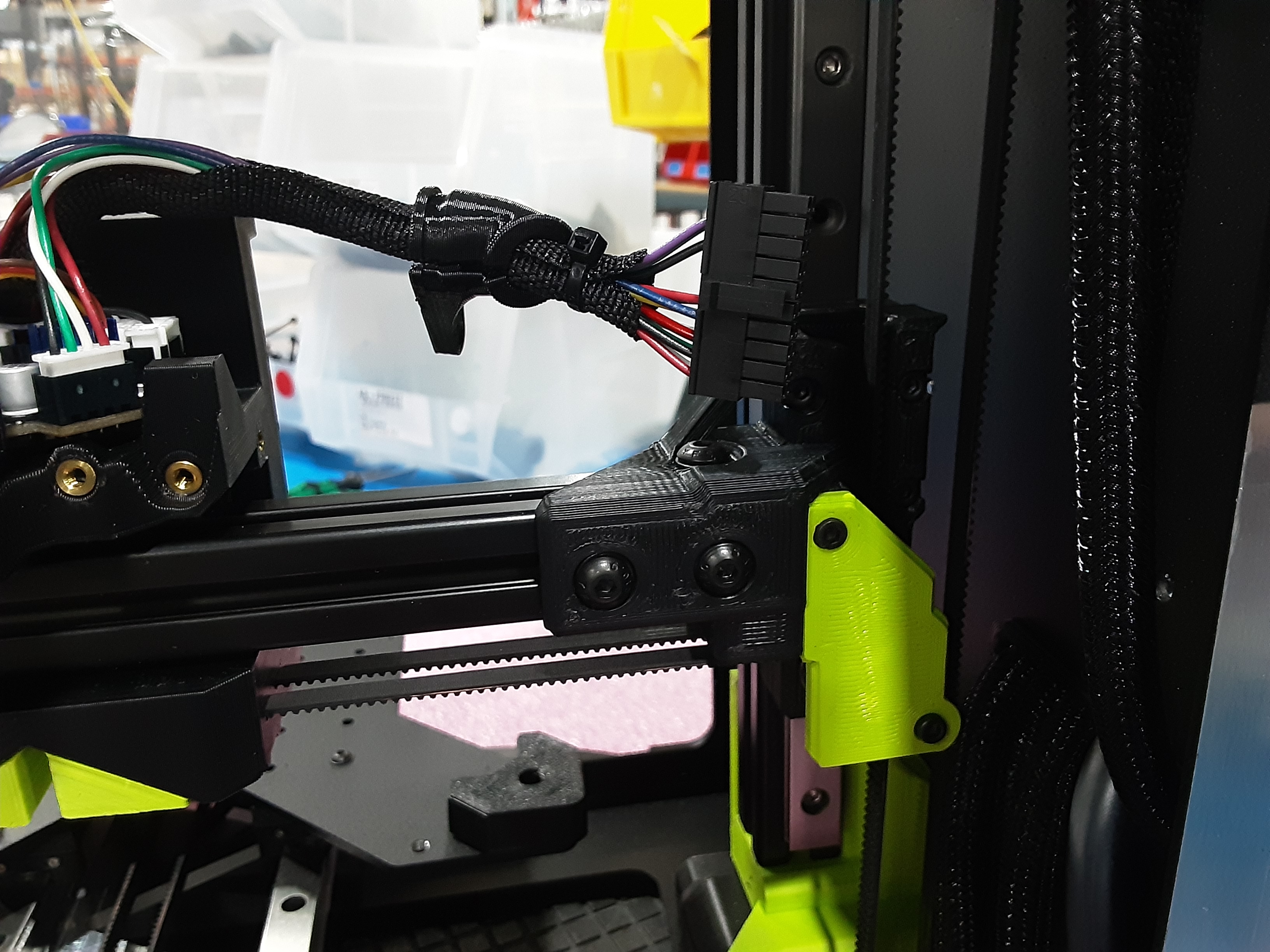
3E) Grab AS-CB0212 x1 and route through PP-GP0890 as shown.
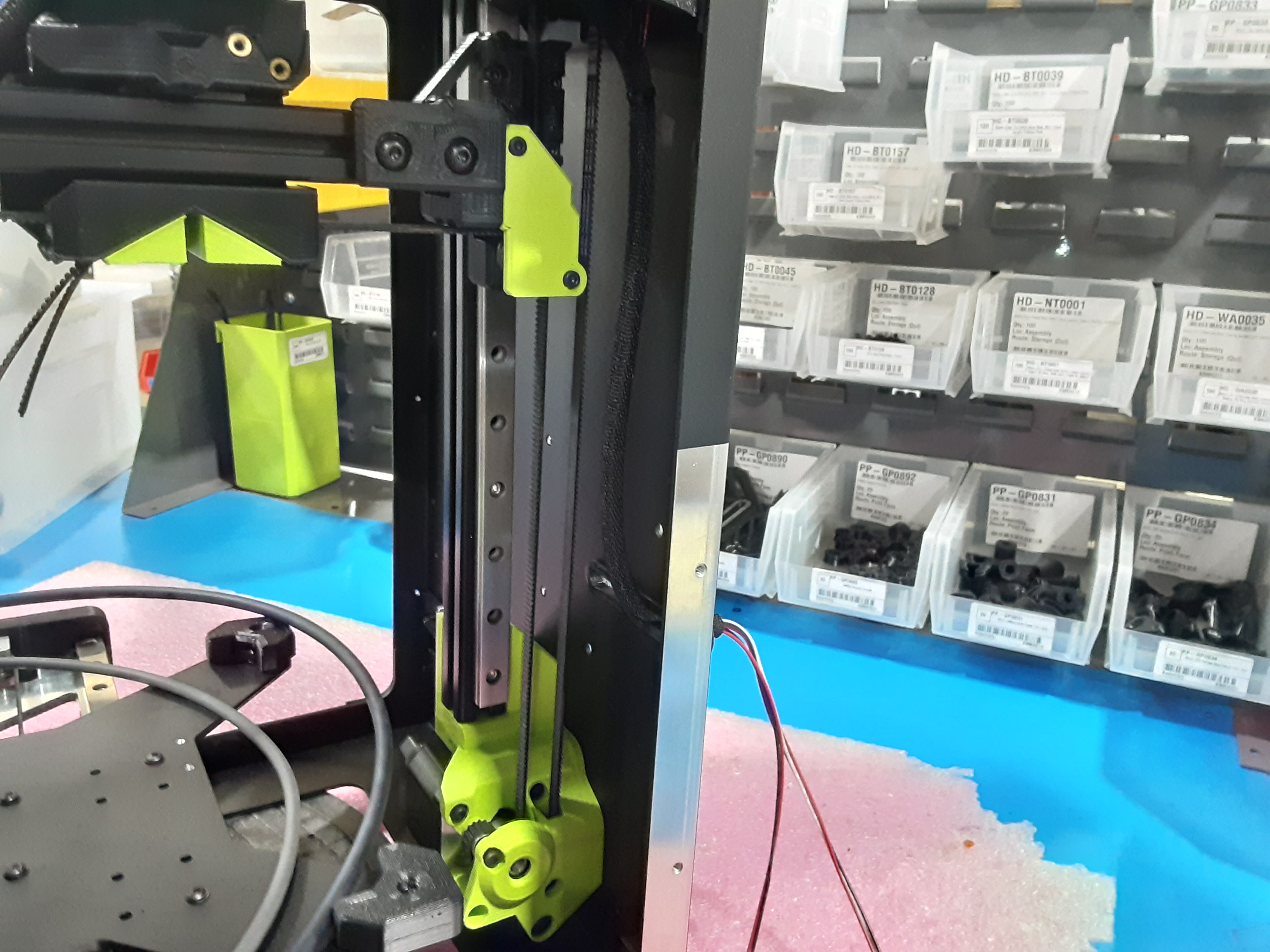
3F) Continue to pull AS-CB0212 into the frame and route through PP-GP0893 from the F.A. as shown.
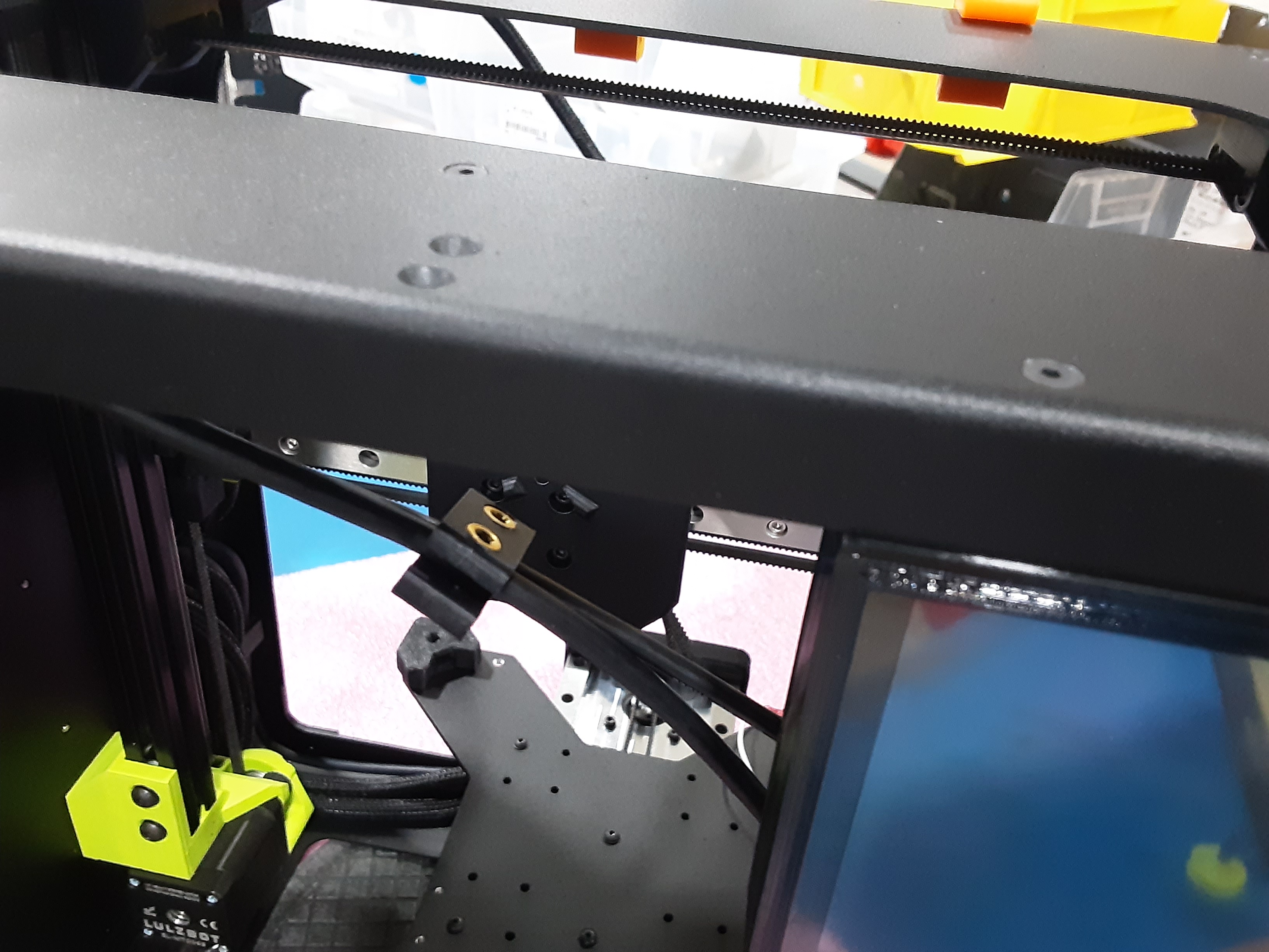
3G) Put PP-GP0892 on AS-CB0211 and install it into PP-GP0893.
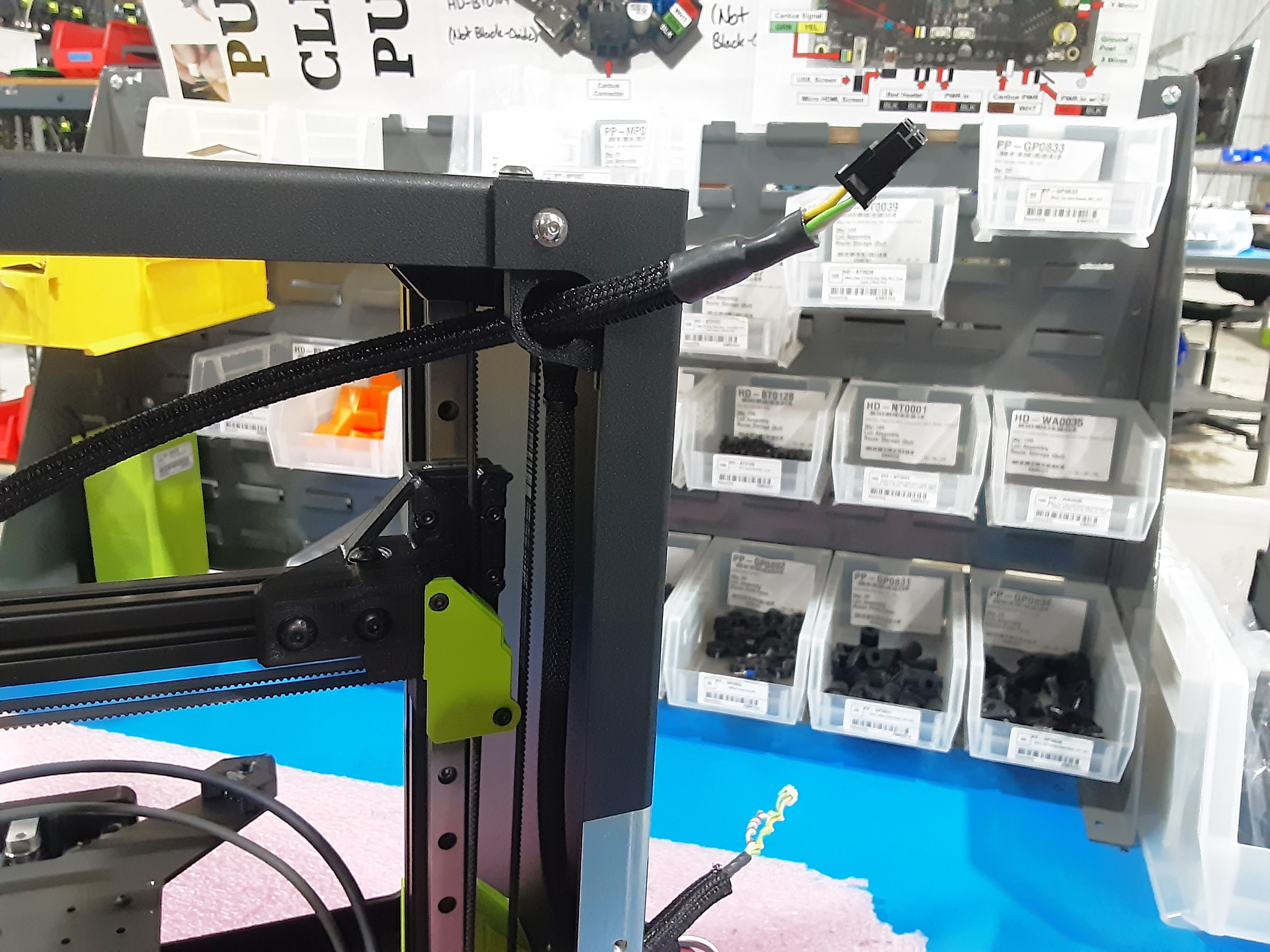
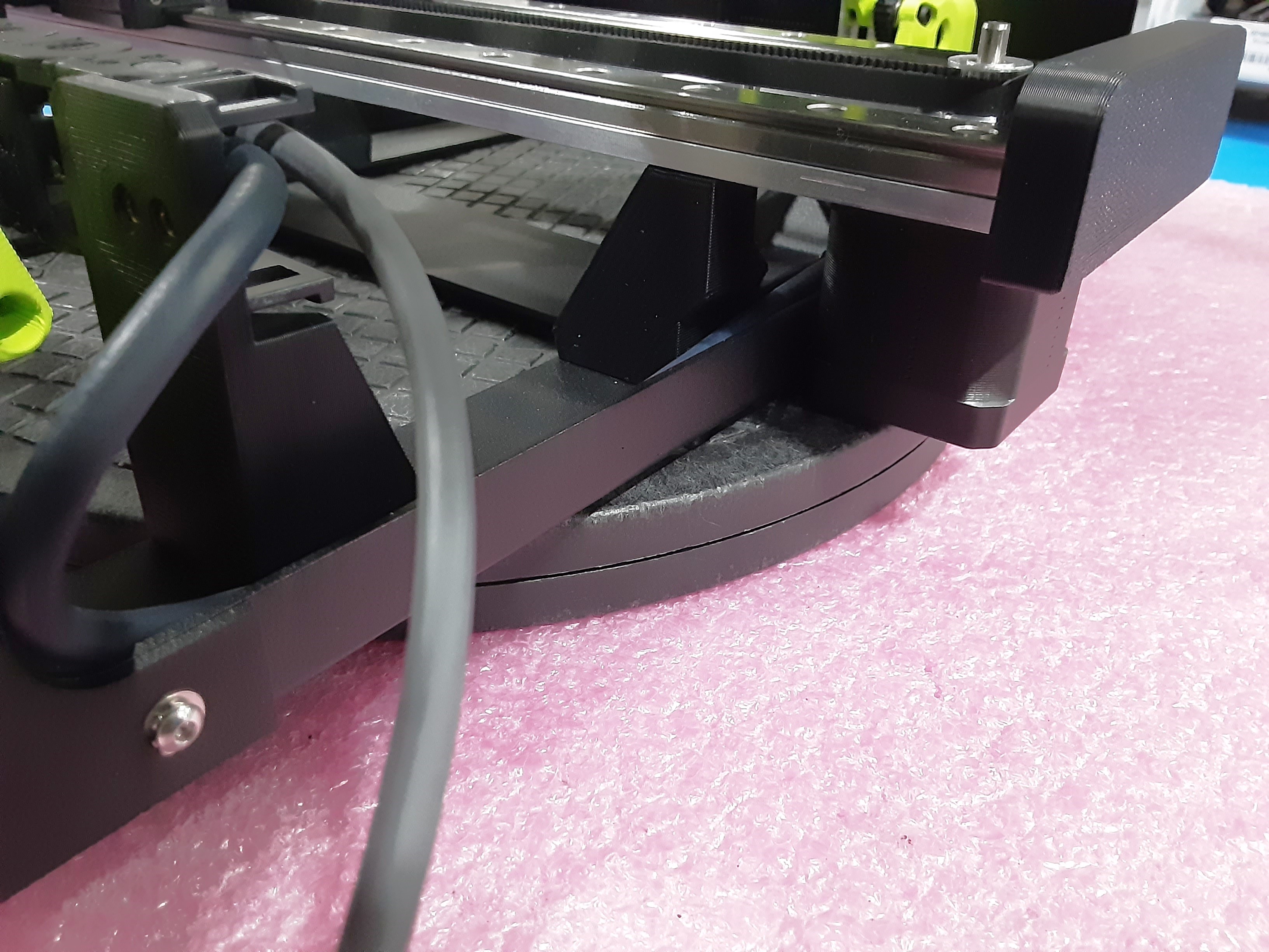
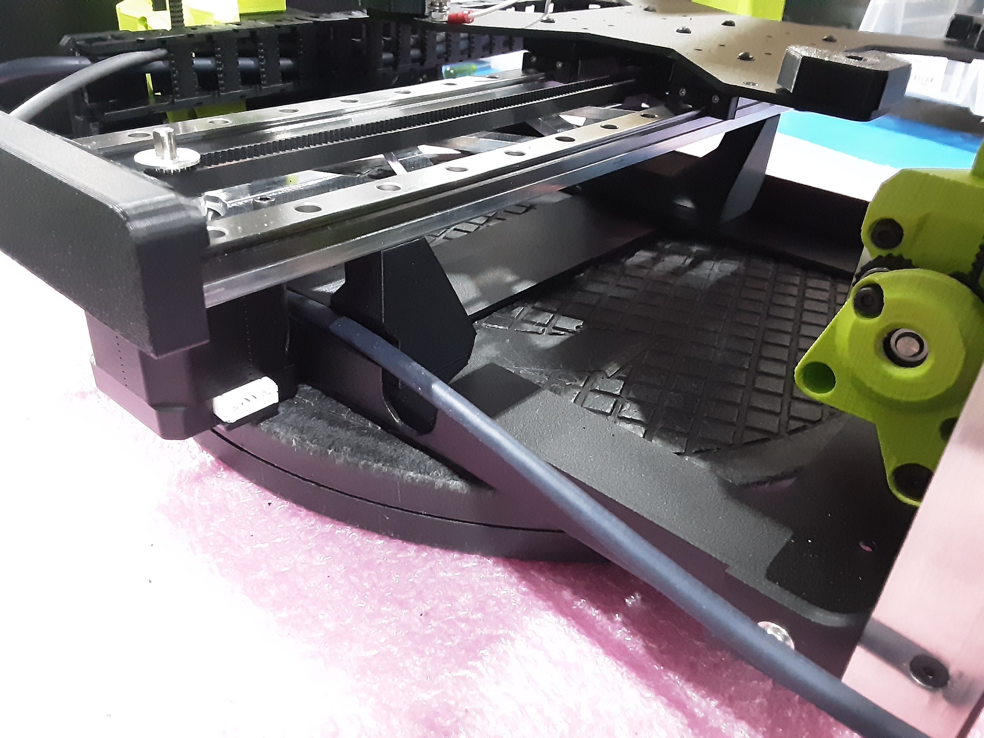
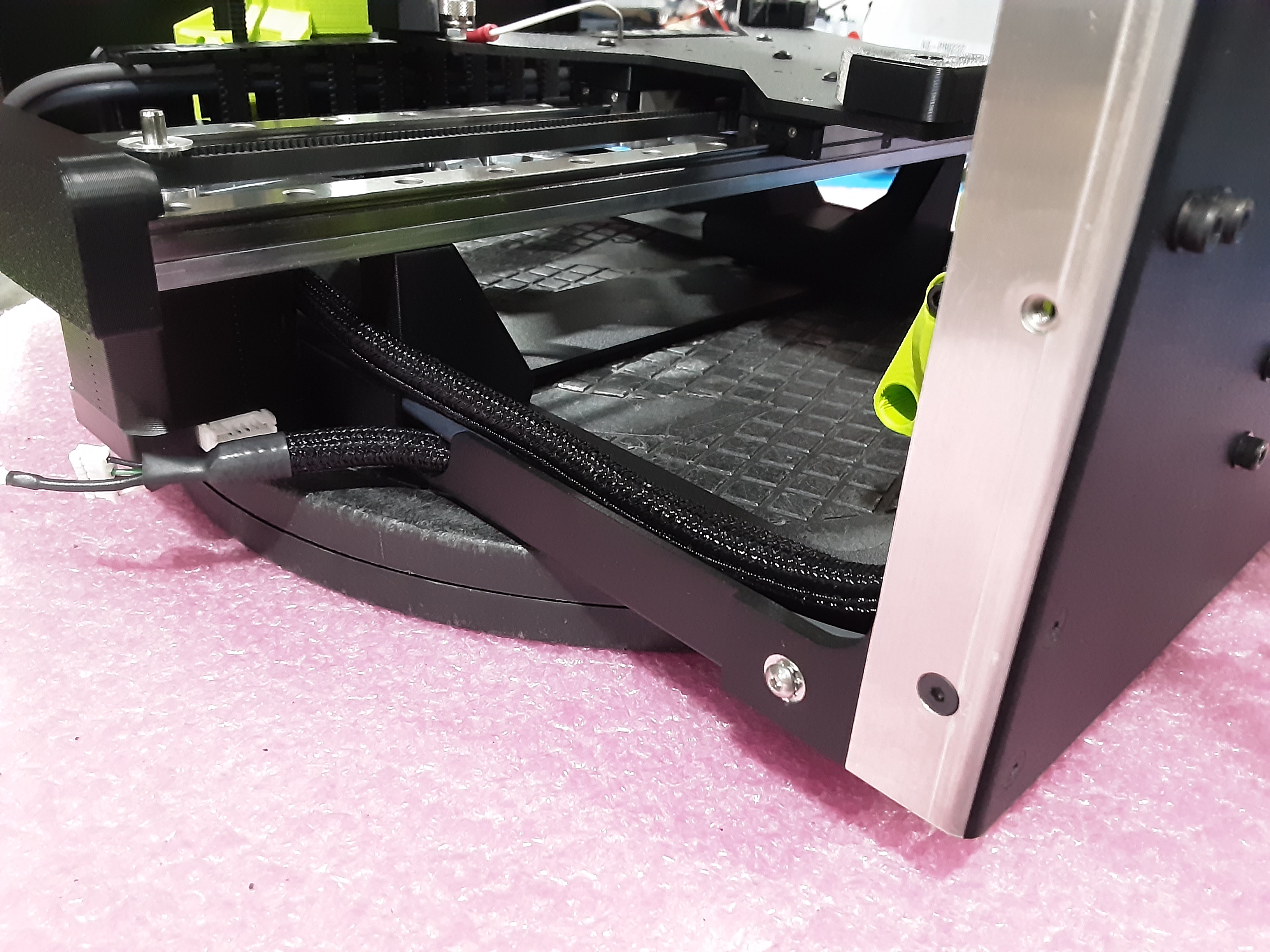
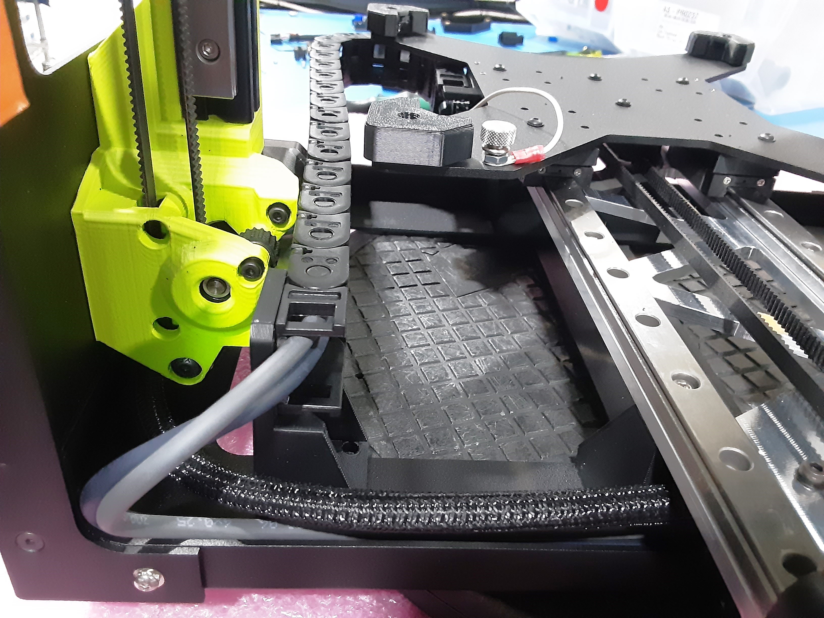
3H) Route dark gray wire from AS-CB0218 on the Y.A.B. under the Y.A.B. and through PP-GP0890 as shown.
3I) Route light gray wire from AS-CB0218 on the Y.A.B. under the Y.A.B. and through PP-GP0890 as shown.
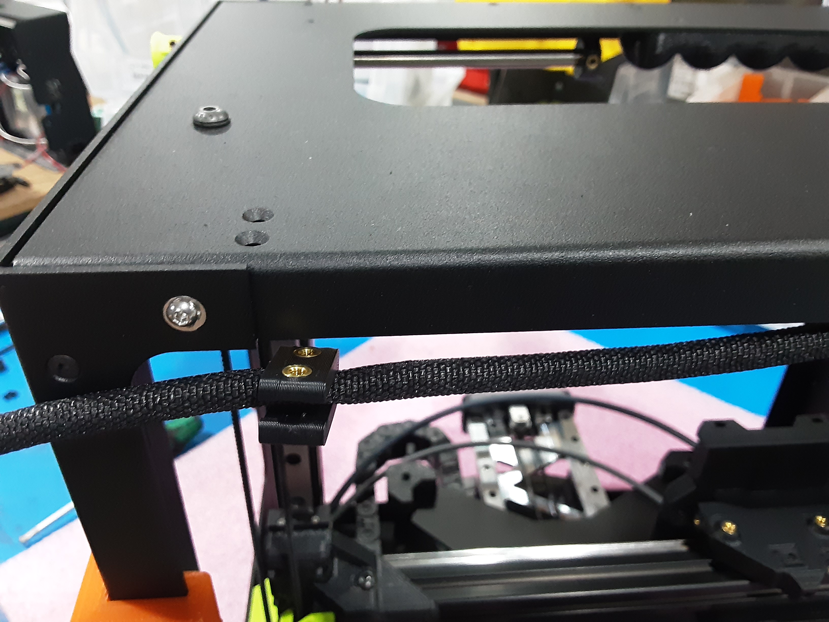
3J) Slide PP-GP0833 x1 over gray wires with the opening of the “U” shape facing the back of the frame and loosely attach to the F.A. using HD-BT0157 x2 and HD-WA0038 x2.
3K) Adjust the gray wires to have a slight loop at the end of the chain.
3L) Tuck the gray wires into the corner of the frame and then tighten the HD-BT0157 x2 in PP-GP0833.
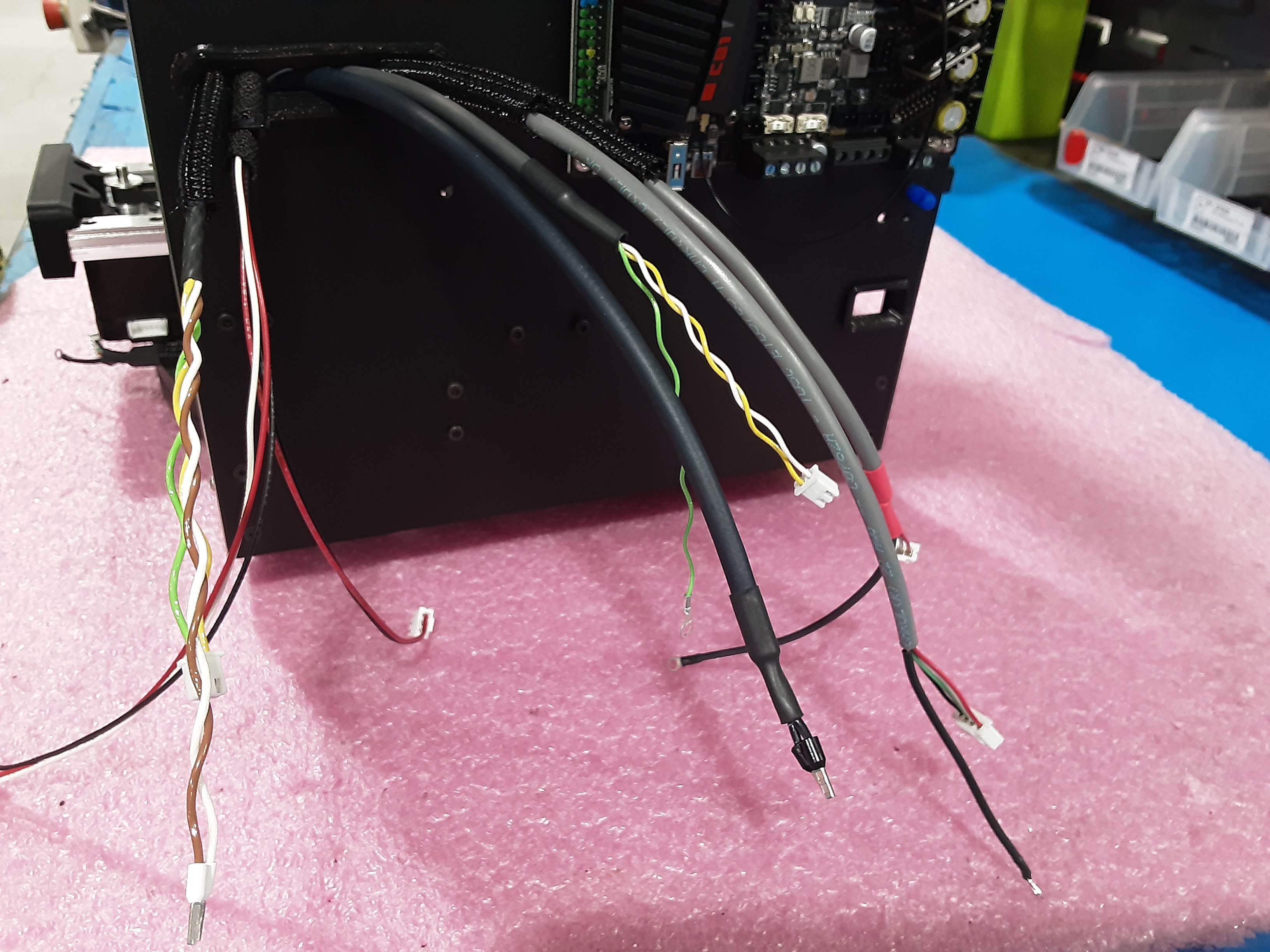
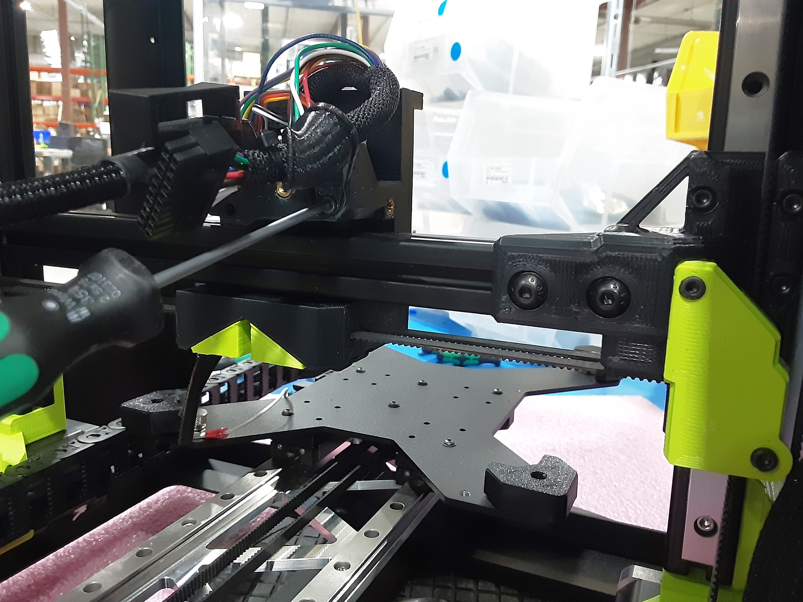
3M) Remove the zip tie on AS-CB0214 to have three separate wire lengths.
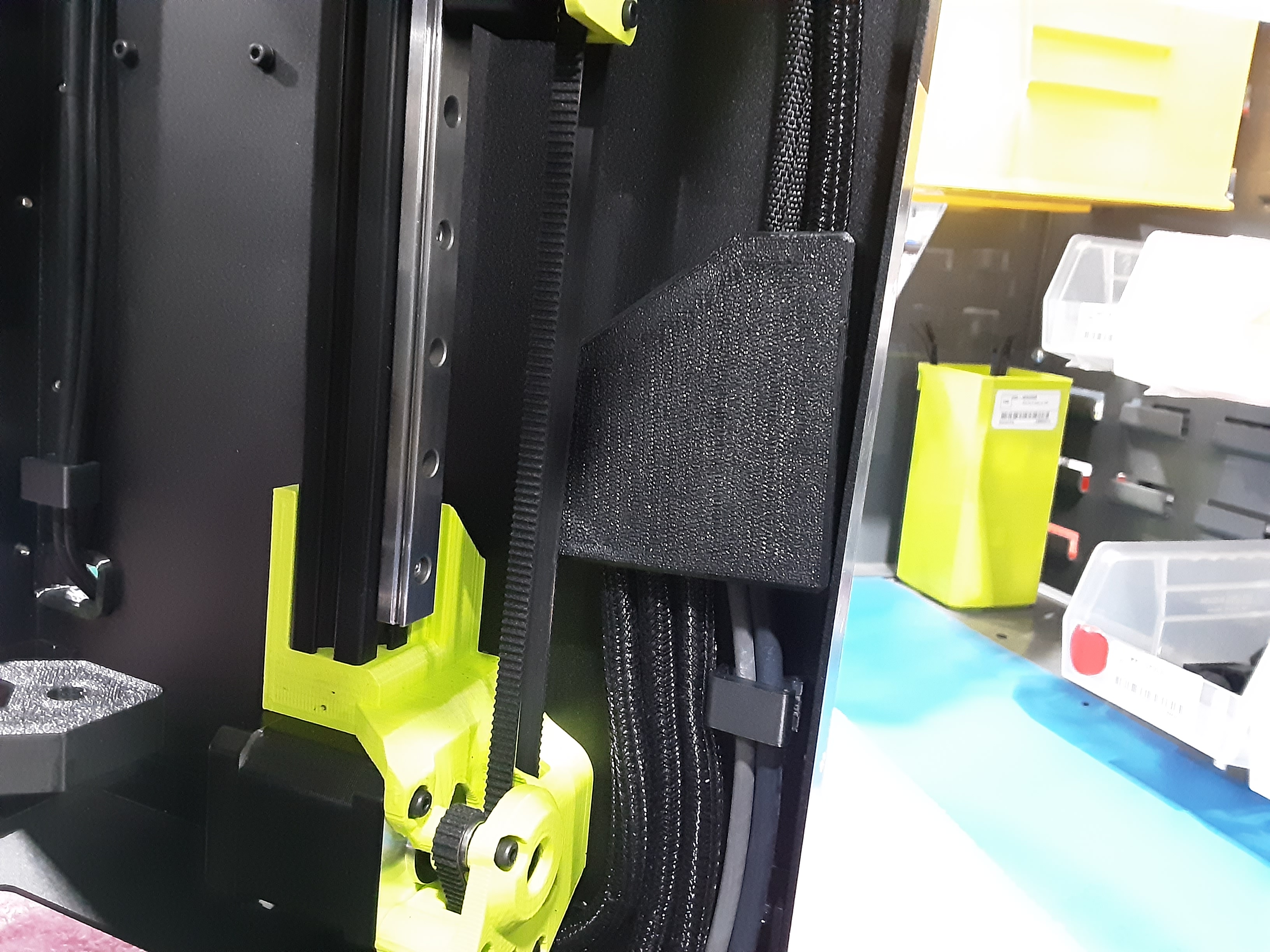
3N) Route the shortest wire from AS-CB0214 through PP-GP0890 as shown. Route the end with heat shrink over the braiding under the Z.L.L. rail assembly.
3O) Route the middle length wire from AS-CB0214 through PP-GP0890 as shown. Route the end with heat shrink over the braiding under the grey wires from Y.A.B. and through the “U” cut out in PP-FP0234 from the F.A.
3P) Route the longest wire from AS-CB0214 through PP-GP0890 as shown. Route the end with heat shrink over the braiding along the grey wires from Y.A.B. under the Y.A.B. over to and under the Z.L.R. rail assembly.

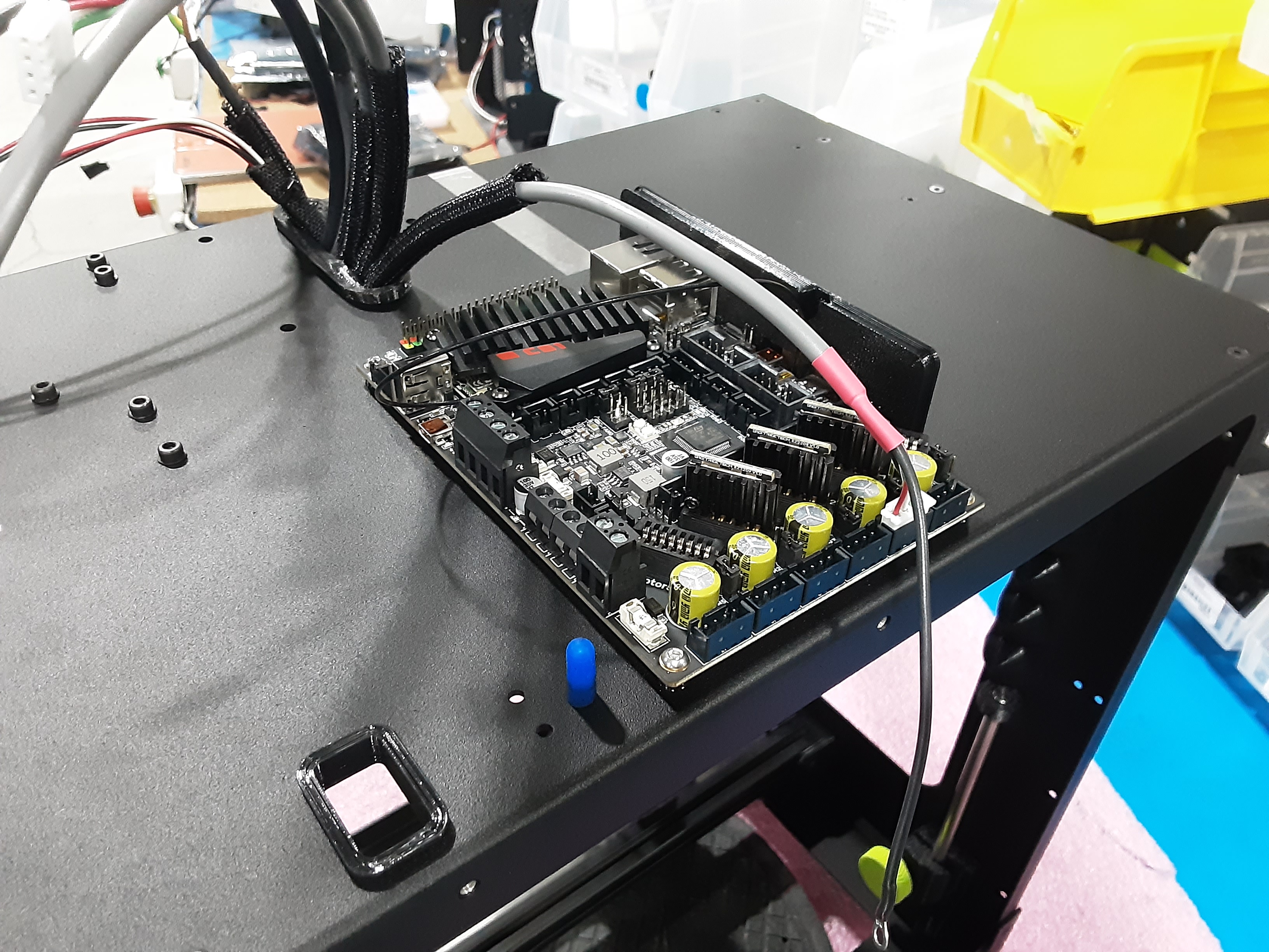
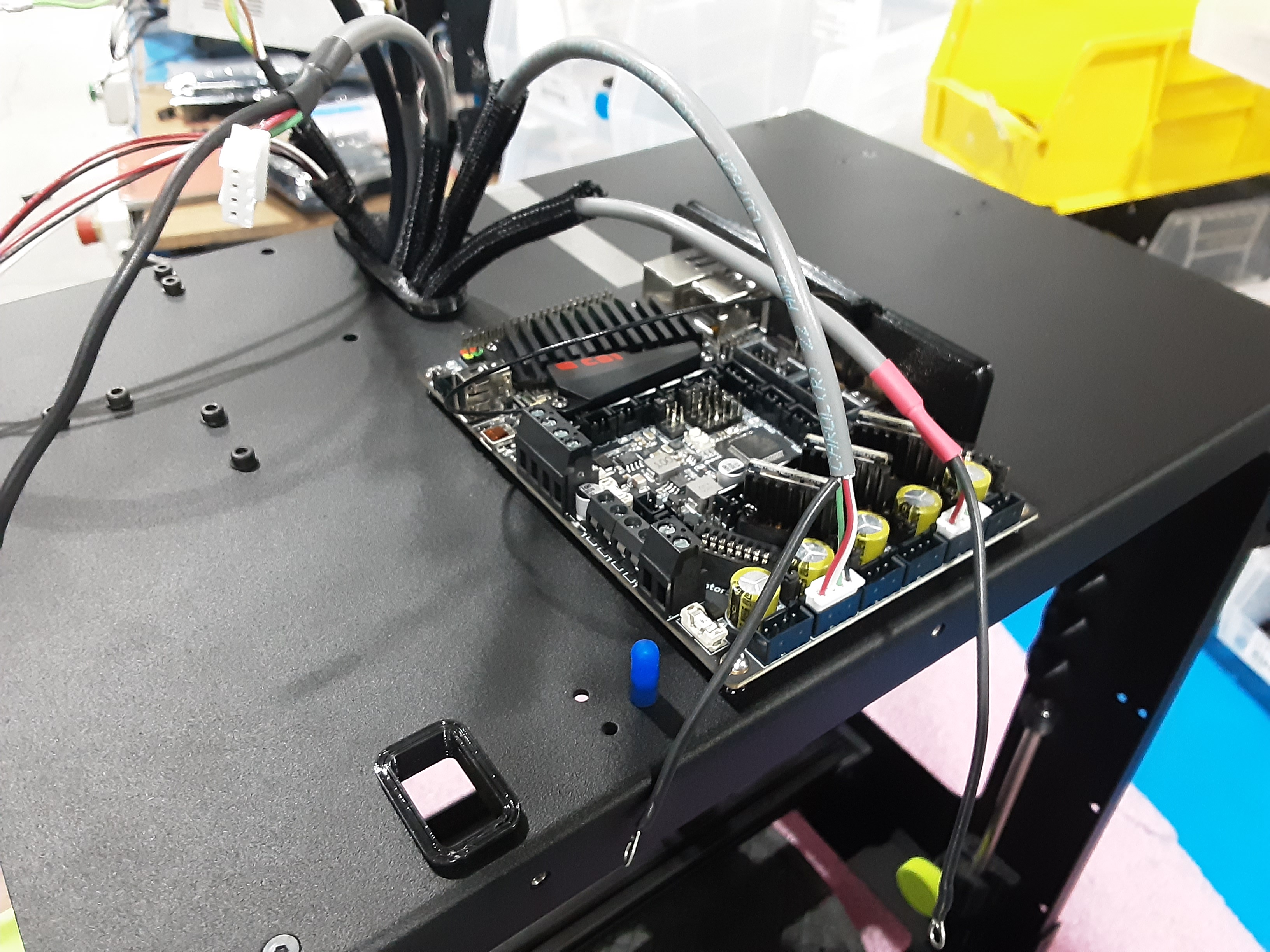
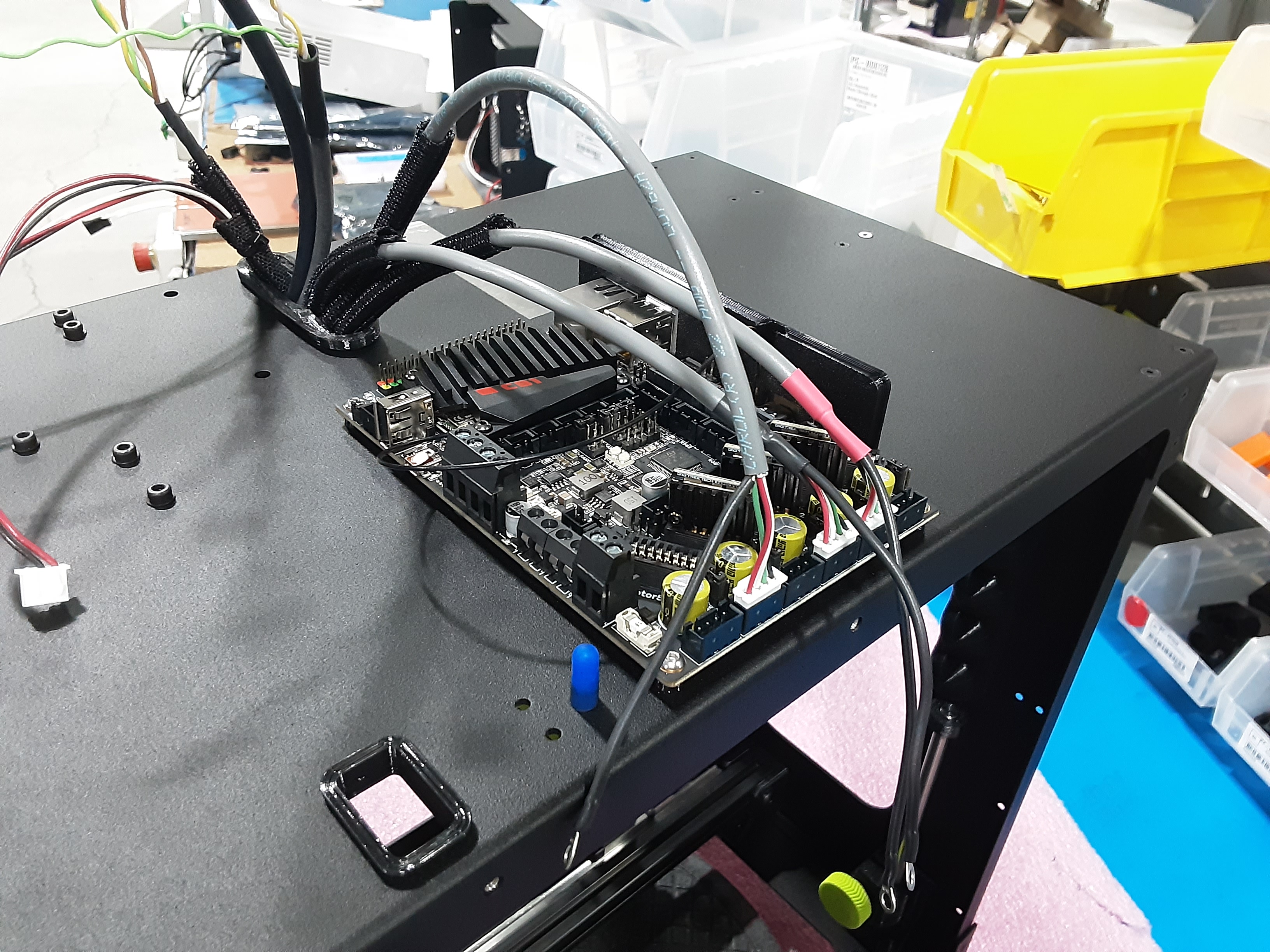
Attach wires to PC-BD0127
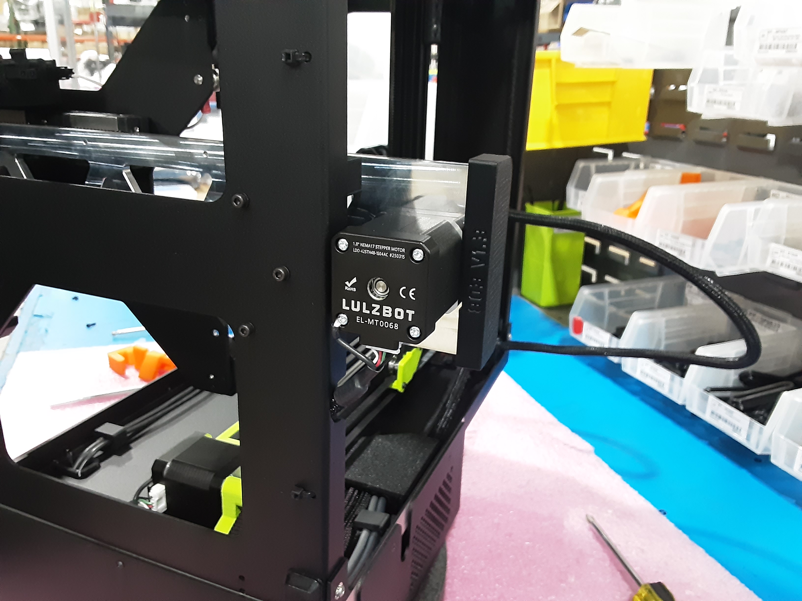
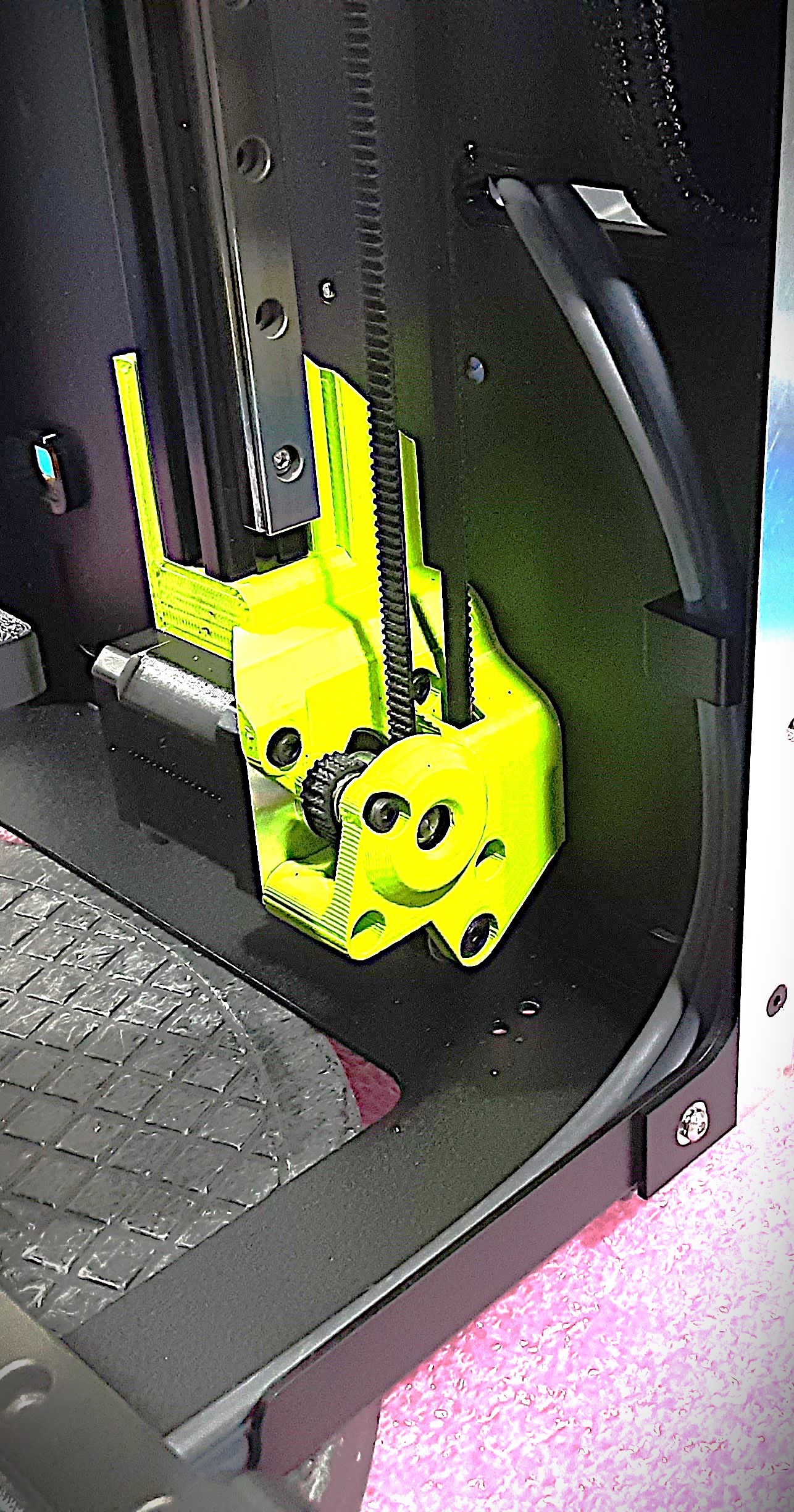
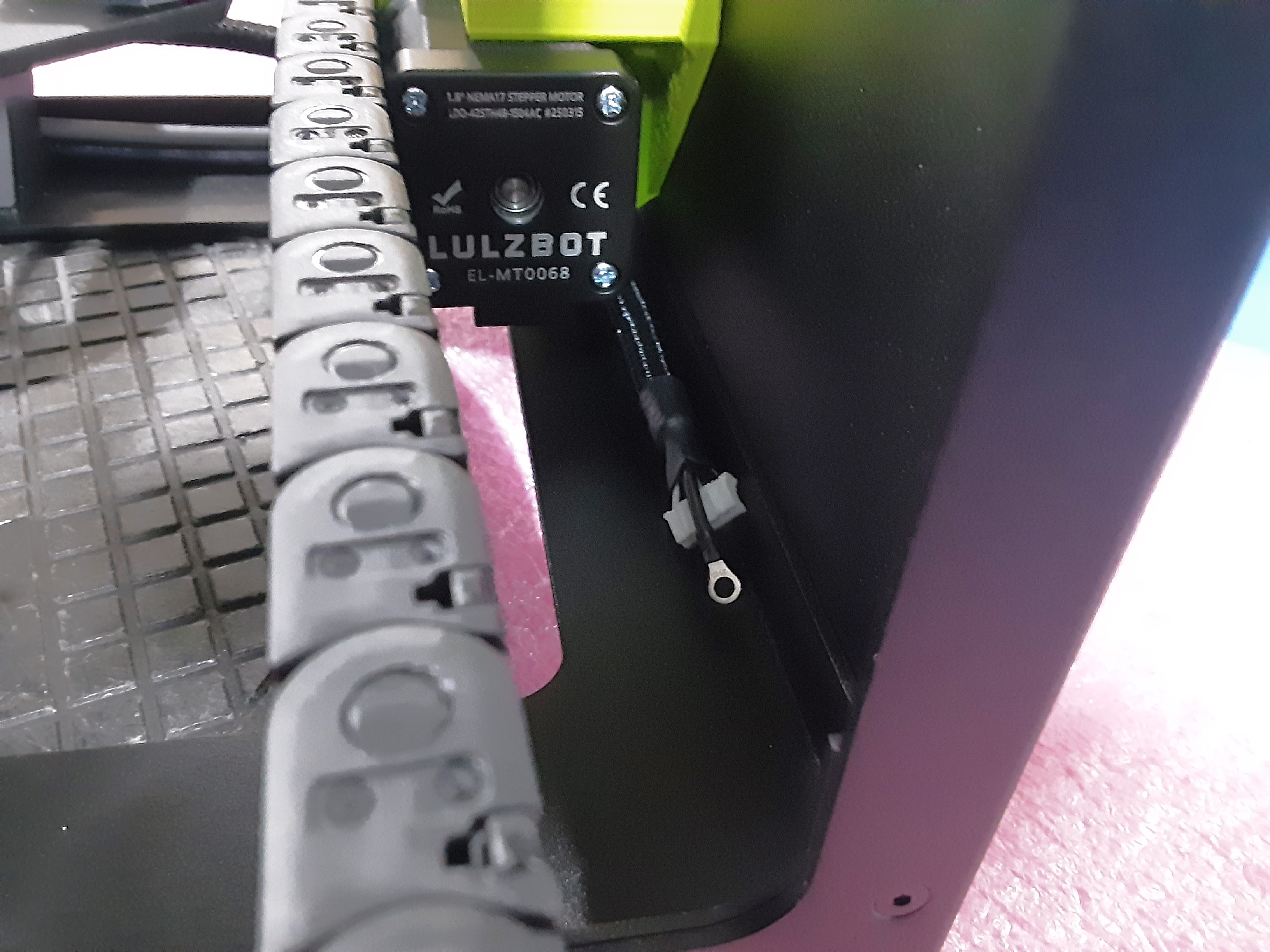
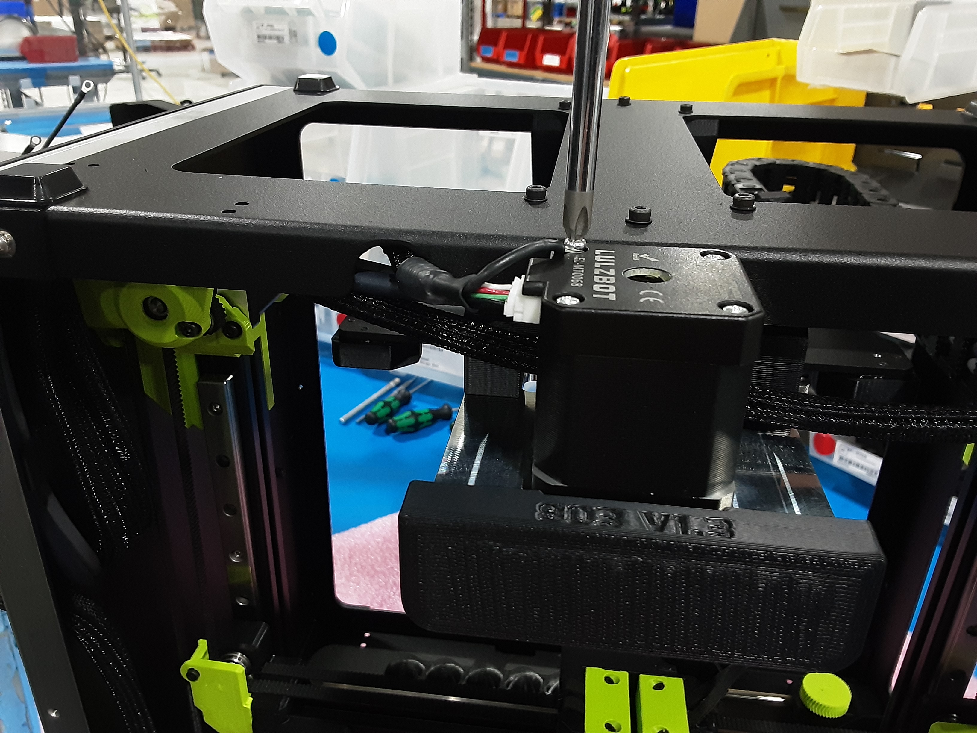
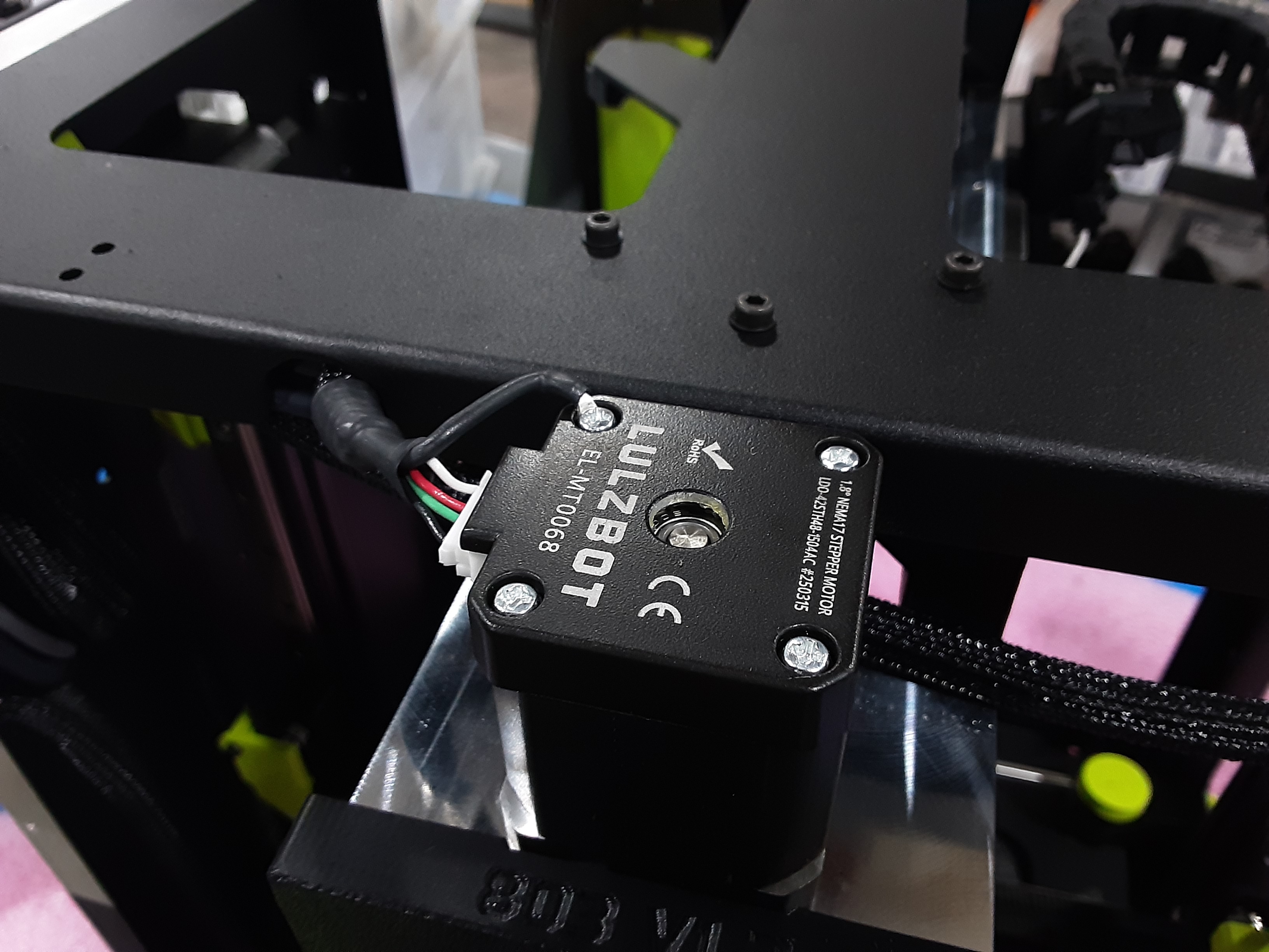
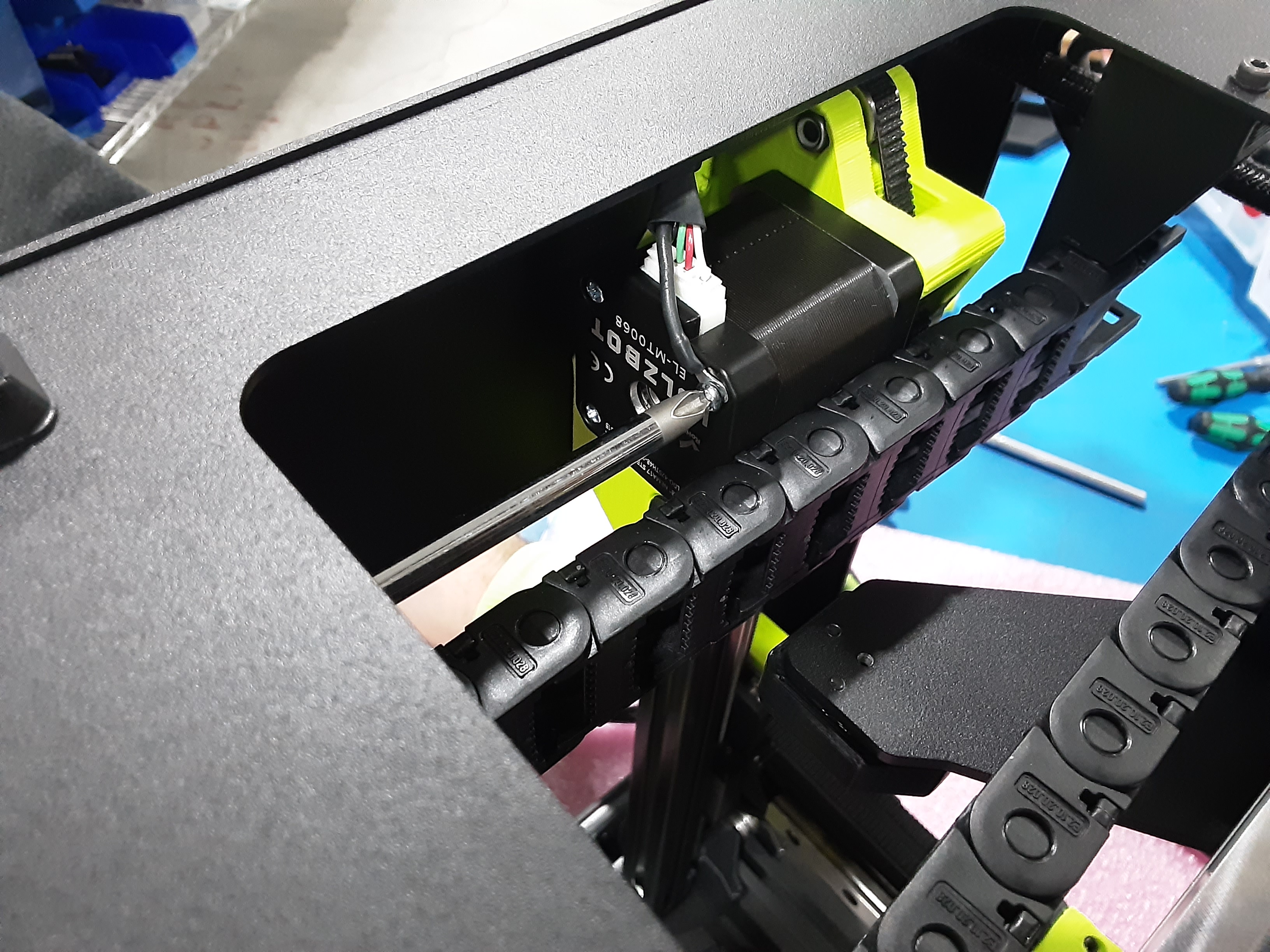
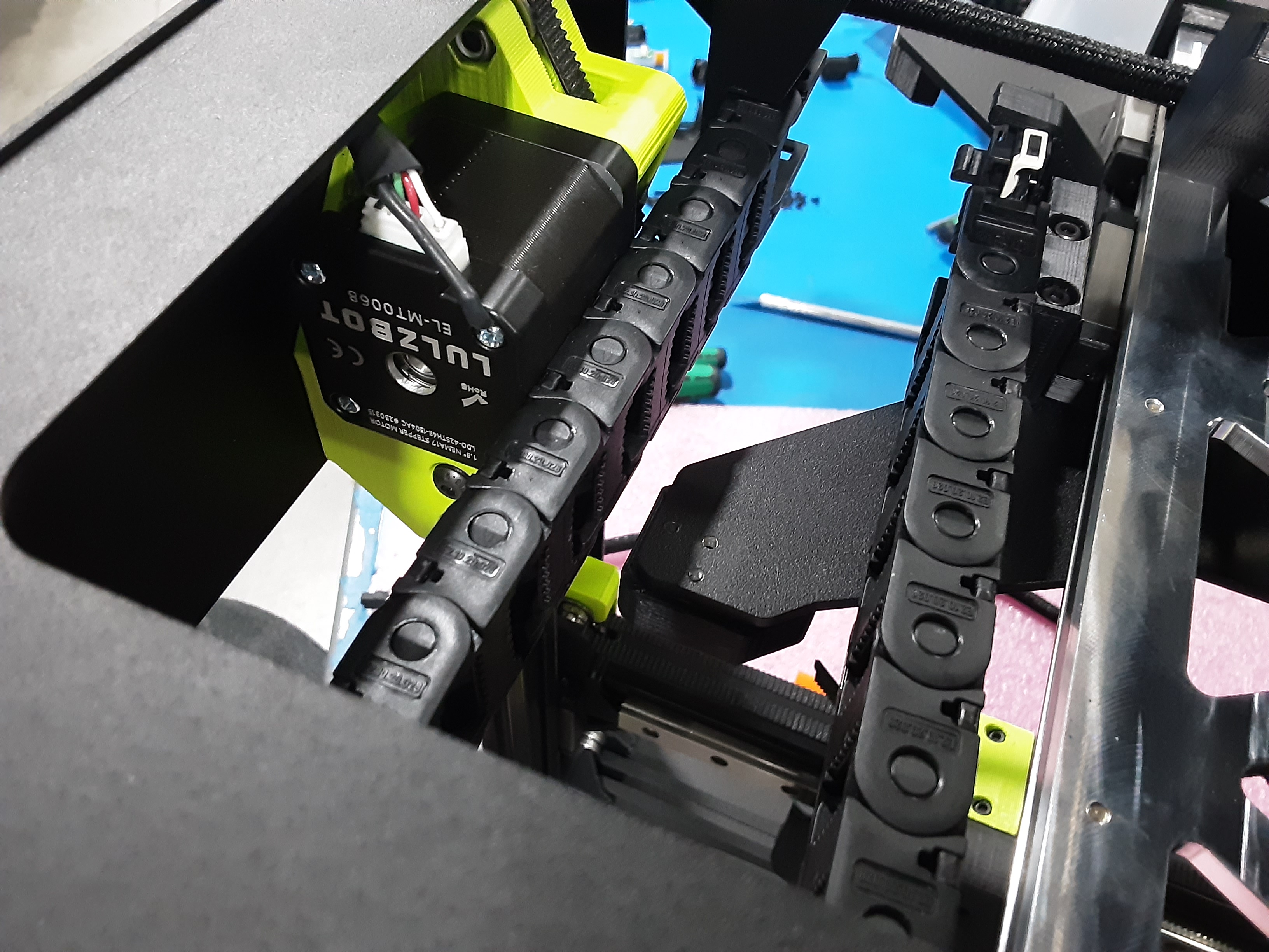
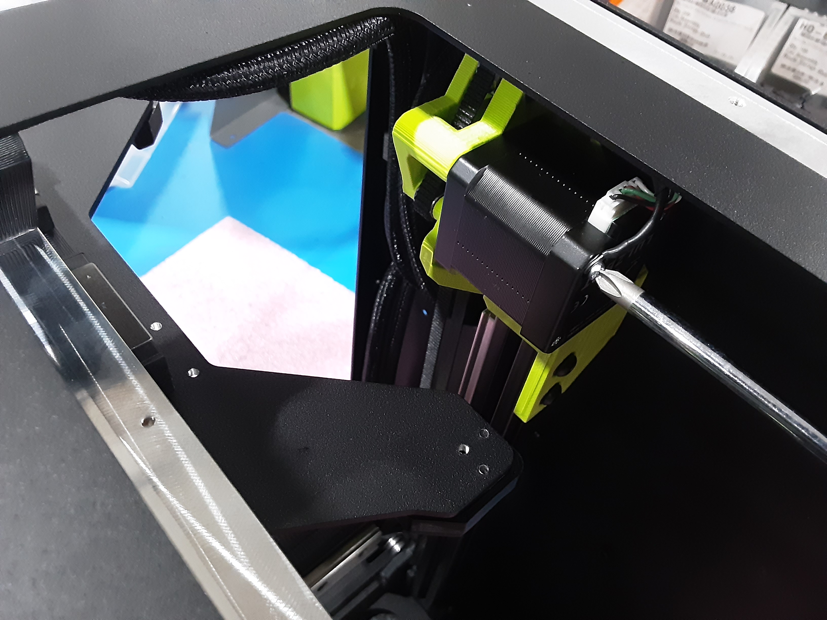
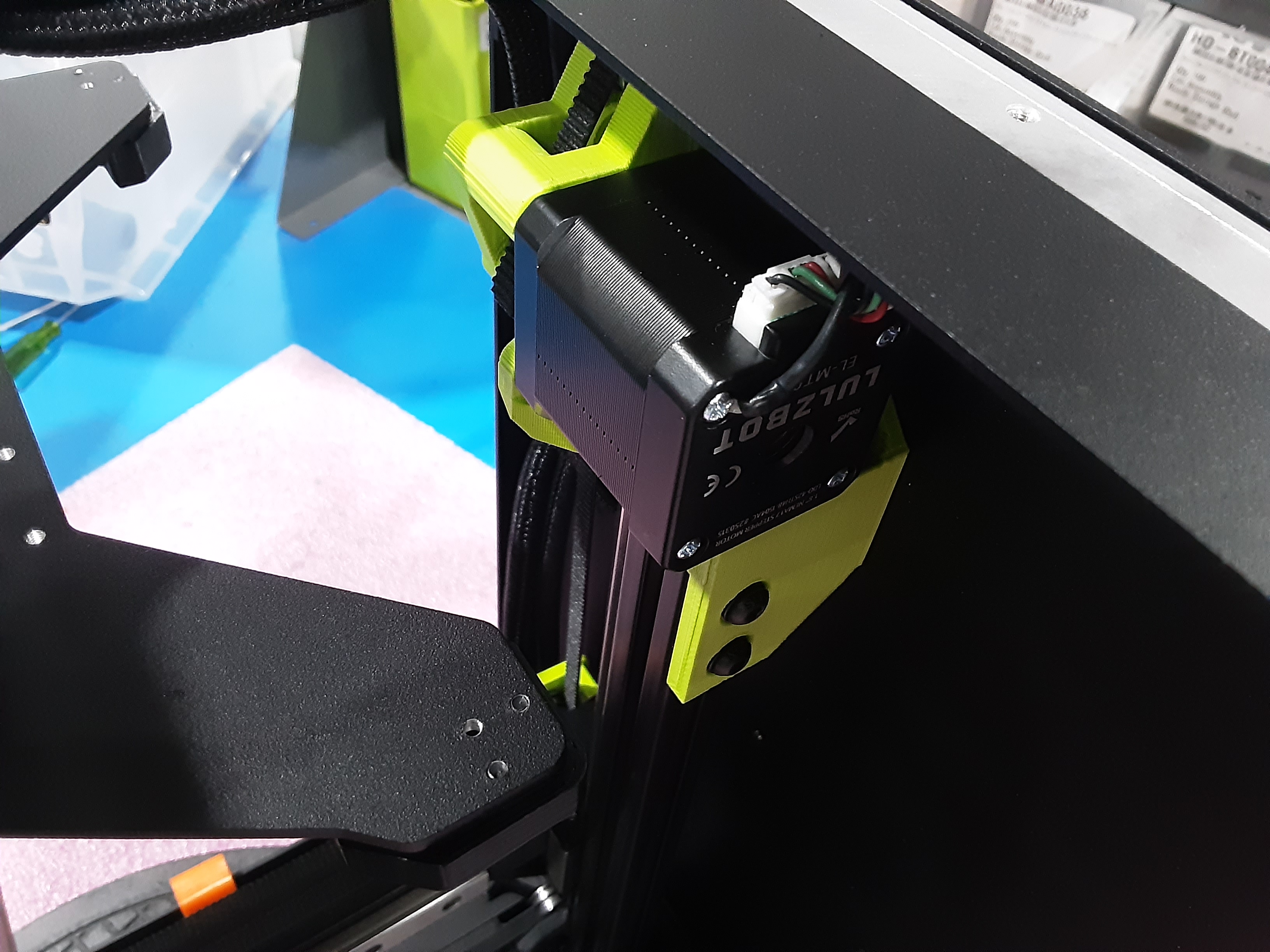
4A) Plug the middle length wire from AS-CB0214 into the motor on the Y.A.B. Remove the screw next to “L” on the bottom of the motor. Place that screw in the ring terminal for the ground wire and reinstall the screw.
4B) Plug the longest length wire from AS-CB0214 into the motor on the Z.L.R. Remove the screw next to “L” on the bottom of the motor. Place that screw in the ring terminal for the ground wire and reinstall the screw.
4C) Plug the shortest length wire from AS-CB0214 into the motor on the Z.L.L. Remove the screw next to “L” on the bottom of the motor. Place that screw in the ring terminal for the ground wire and reinstall the screw.
4D) Make sure the wires from AS-CB0214 are tucked into the corners of the F.A.
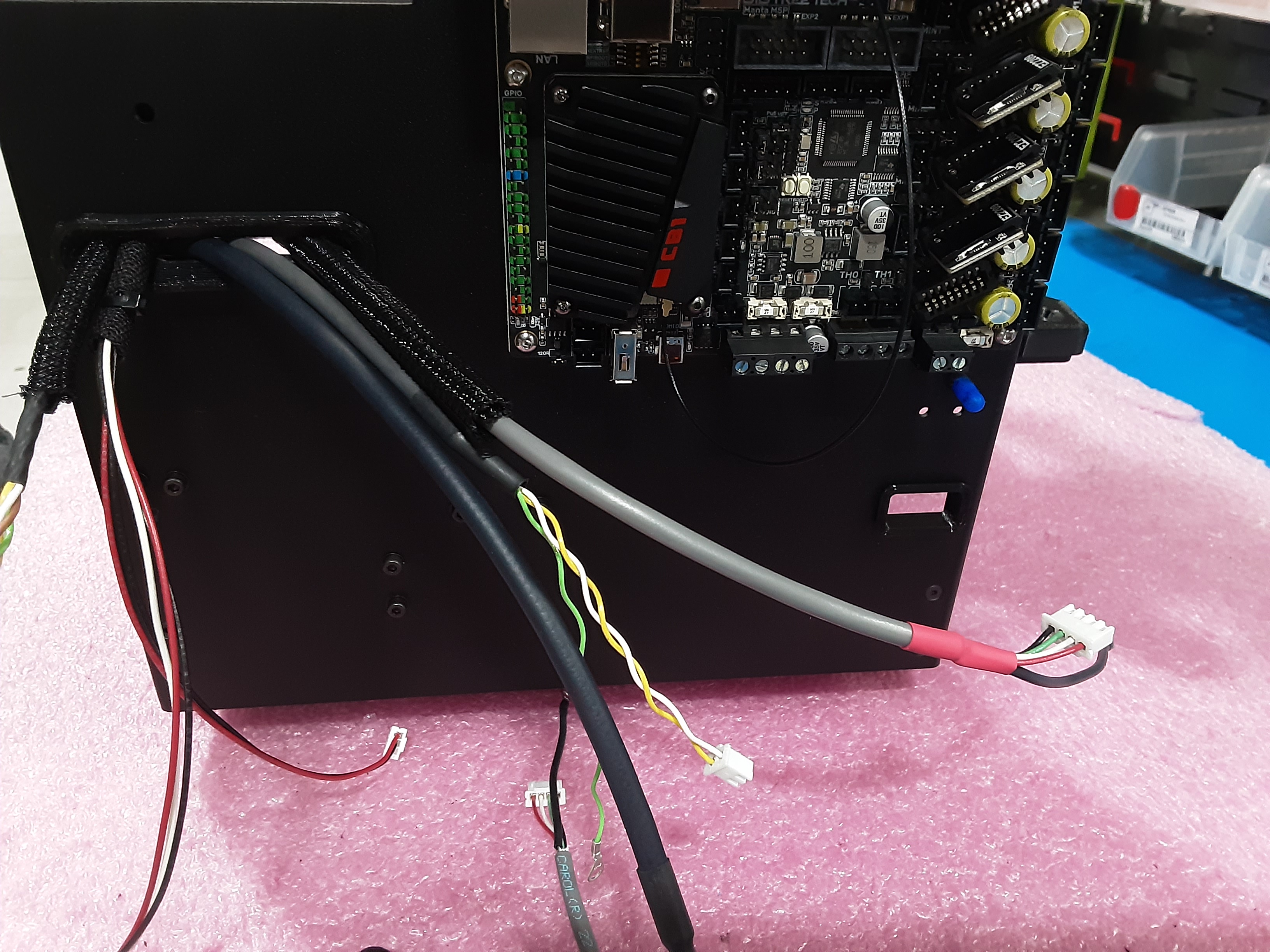
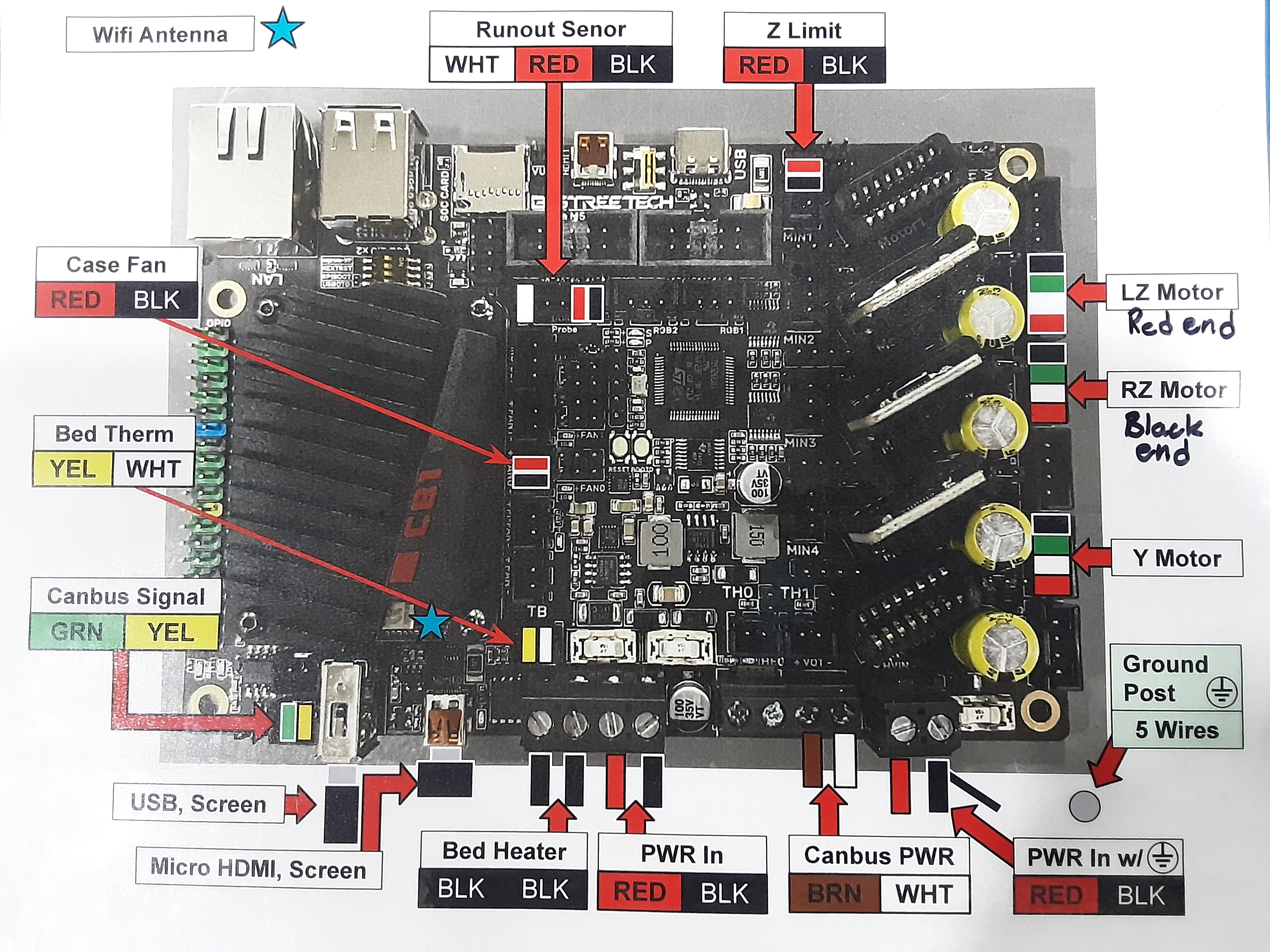
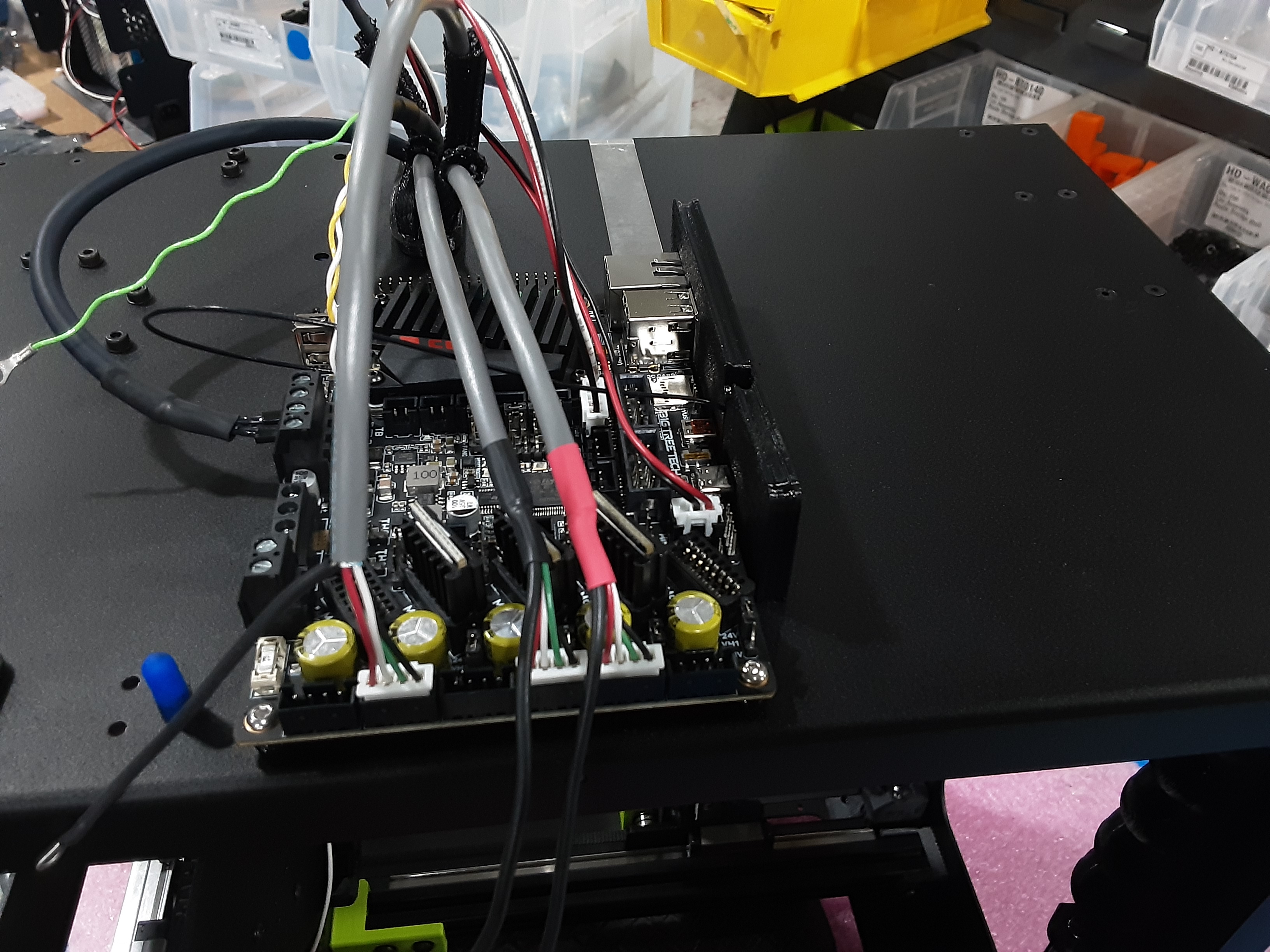
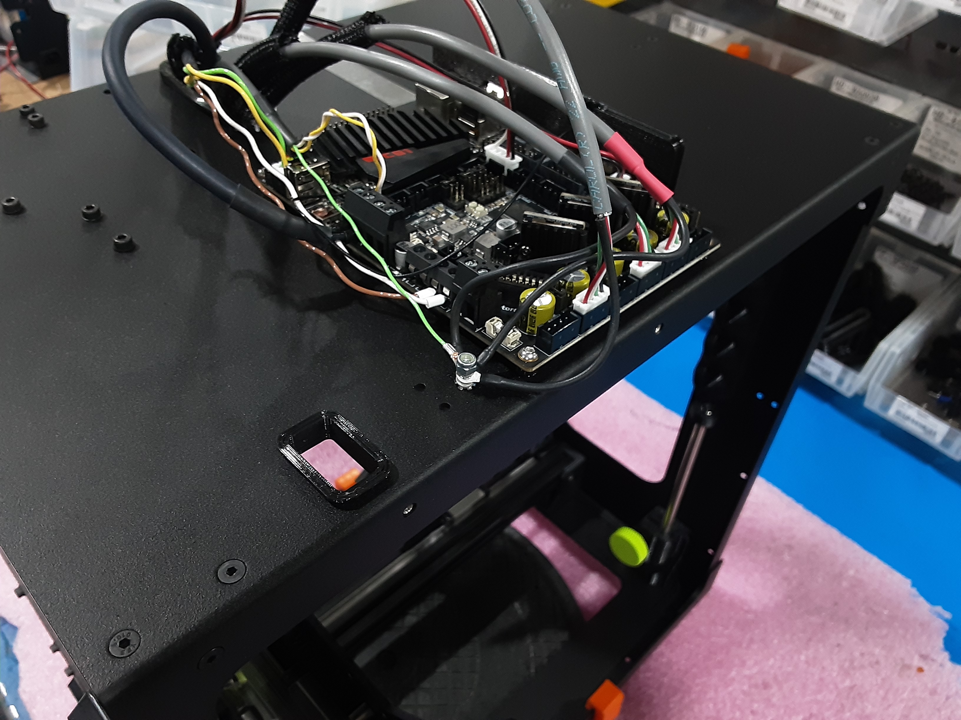
4E) Plug the shortest wire from AS-CB0214 into PC-BD0127 where shown.
4F) Plug the middle length wire from AS-CB0214 into PC-BD0127 where shown.
4G) Plug the longest wire from AS-CB0214 into PC-BD0127 where shown.
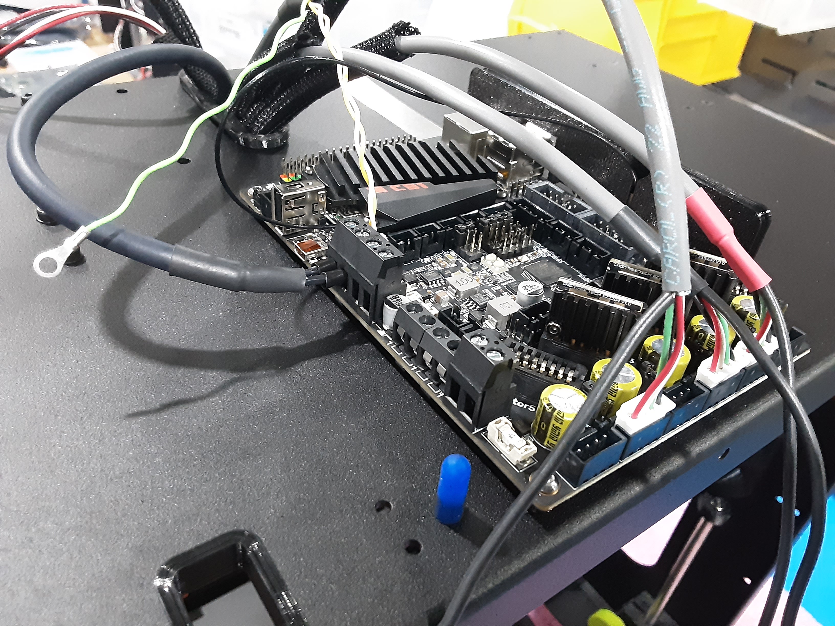
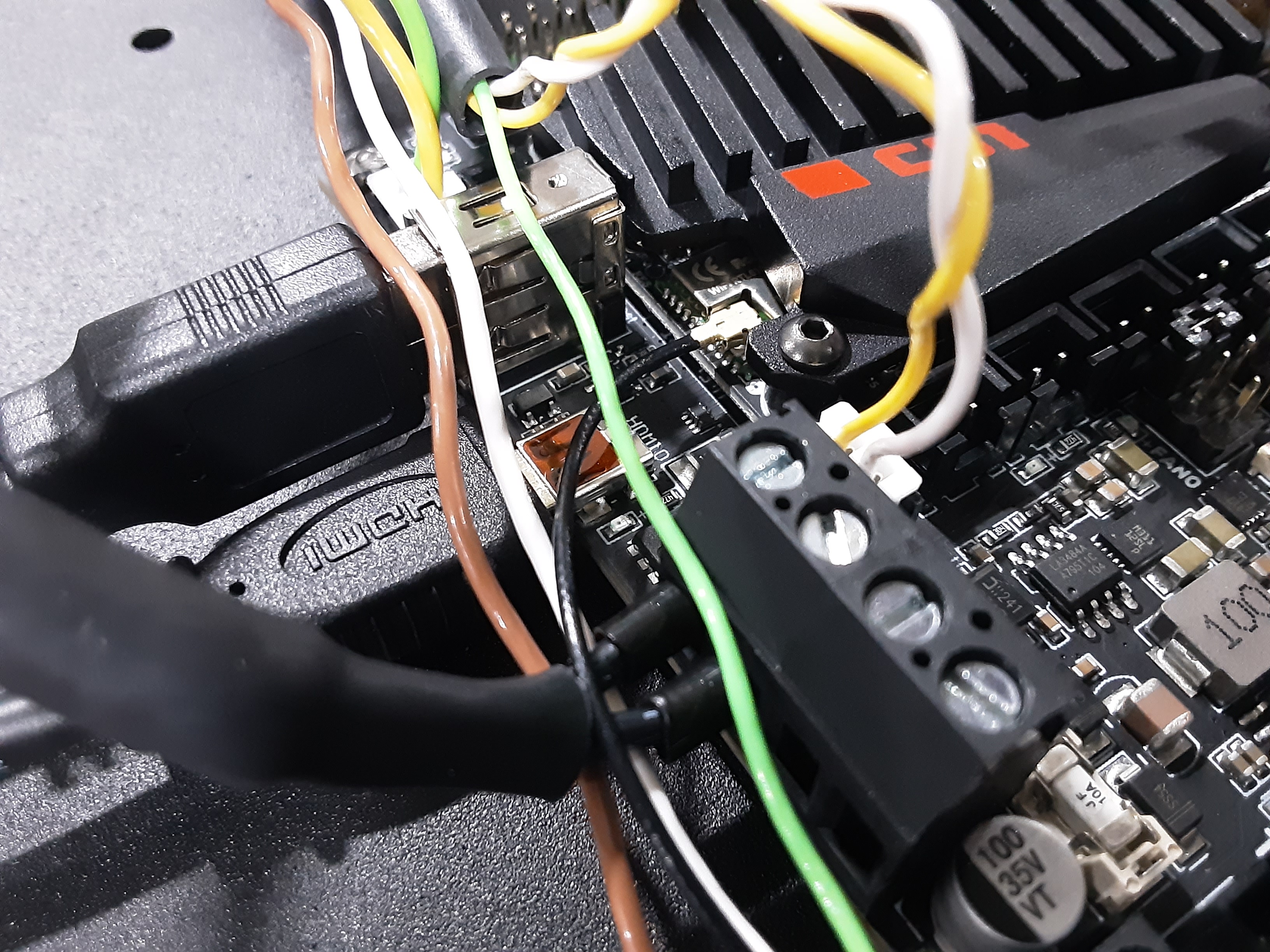
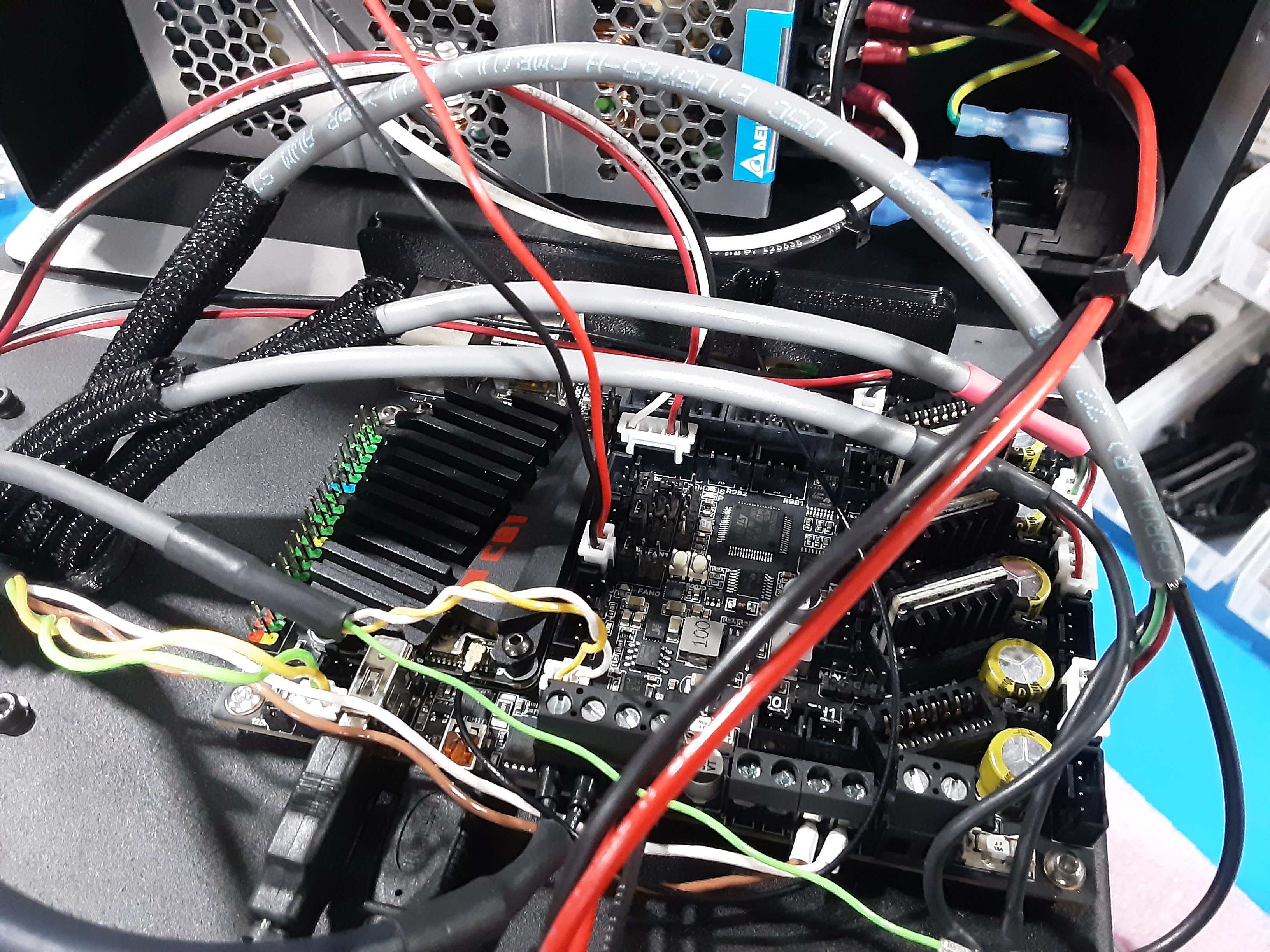
4H) Plug in the light gray wire from Y.A.B. into PC-BD0127 where shown.
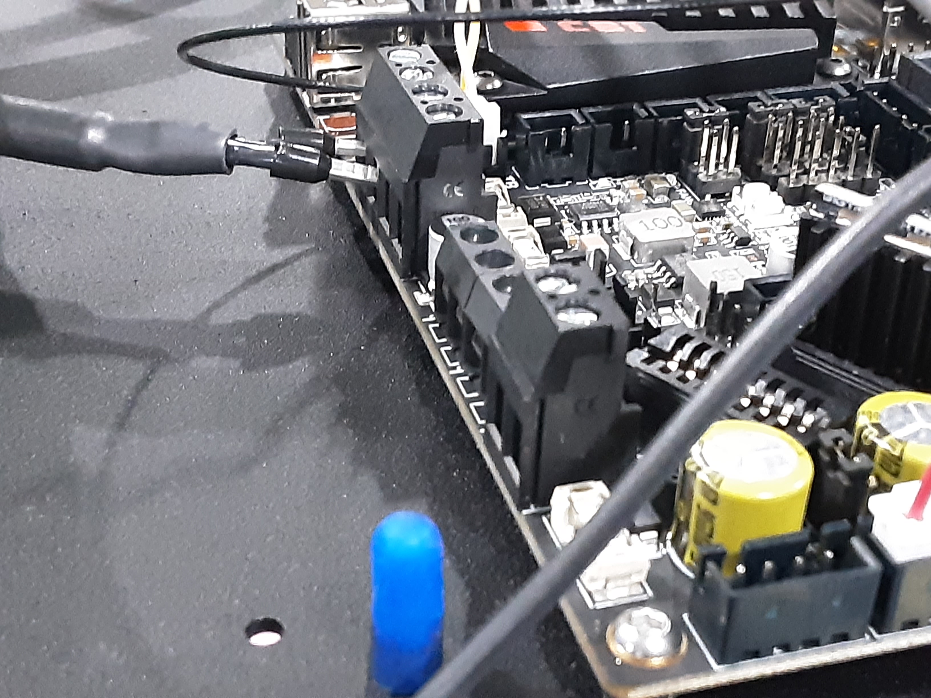
4I) Loosen the shown clamp screws on PC-BD0127. With the longer flat side of the terminals on the dark gray wire from Y.A.B. facing the screw head insert the terminals into the clamps. Tighten the screws to secure the wires.
4J) Plug in the two plugs from EL-HR0214 on the Z.L.L. into PC-BD0127 where shown.
4K) Plug in AS-CB0212 into PC-BD0127 where shown.
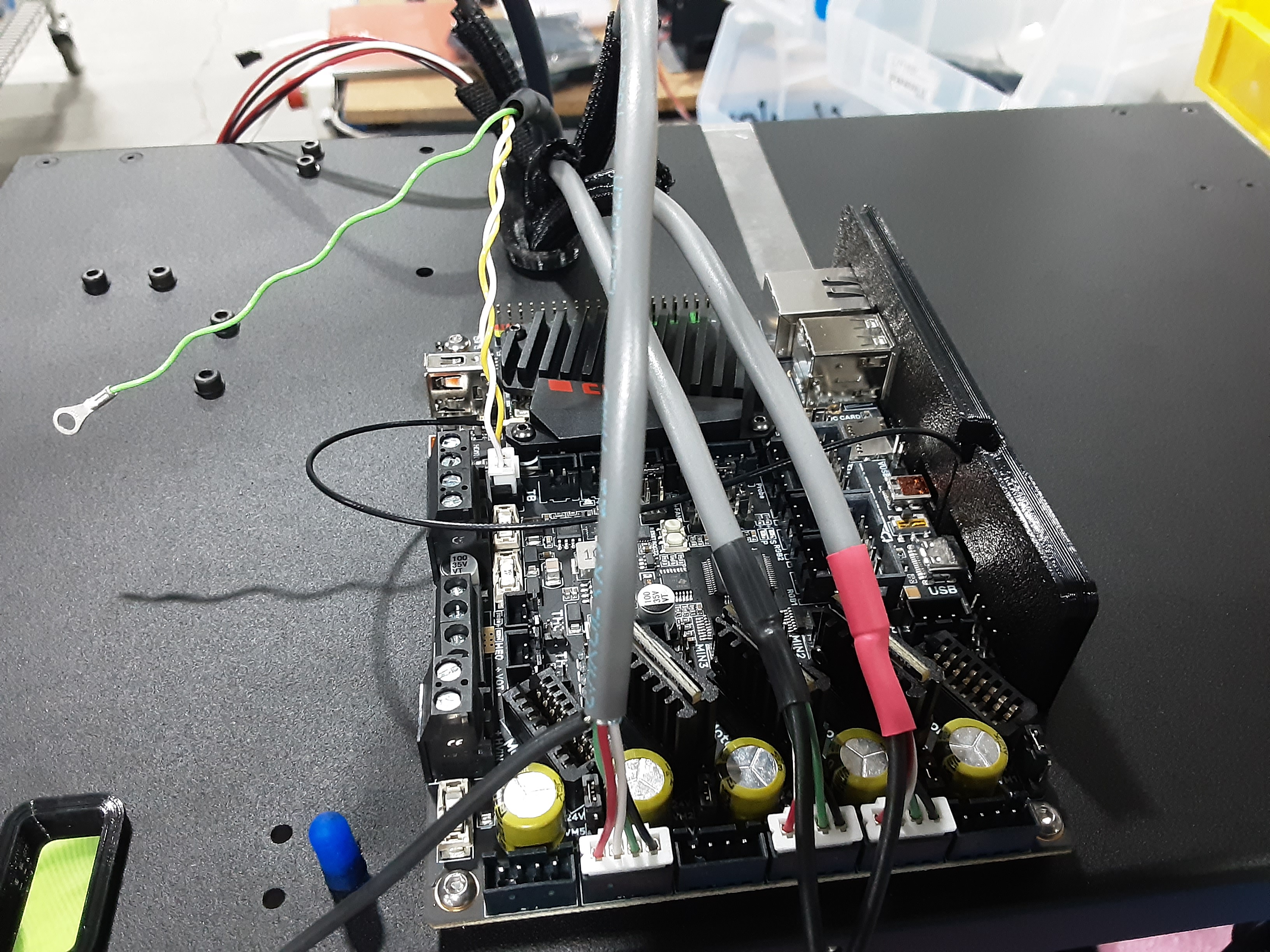
4L) Loosen the shown clamp screws on PC-BD0127. With the longer flat side of the terminals on
AS-CB0212 facing the screw head insert the terminals into the correct clamps. Tighten the screws to secure the wires.
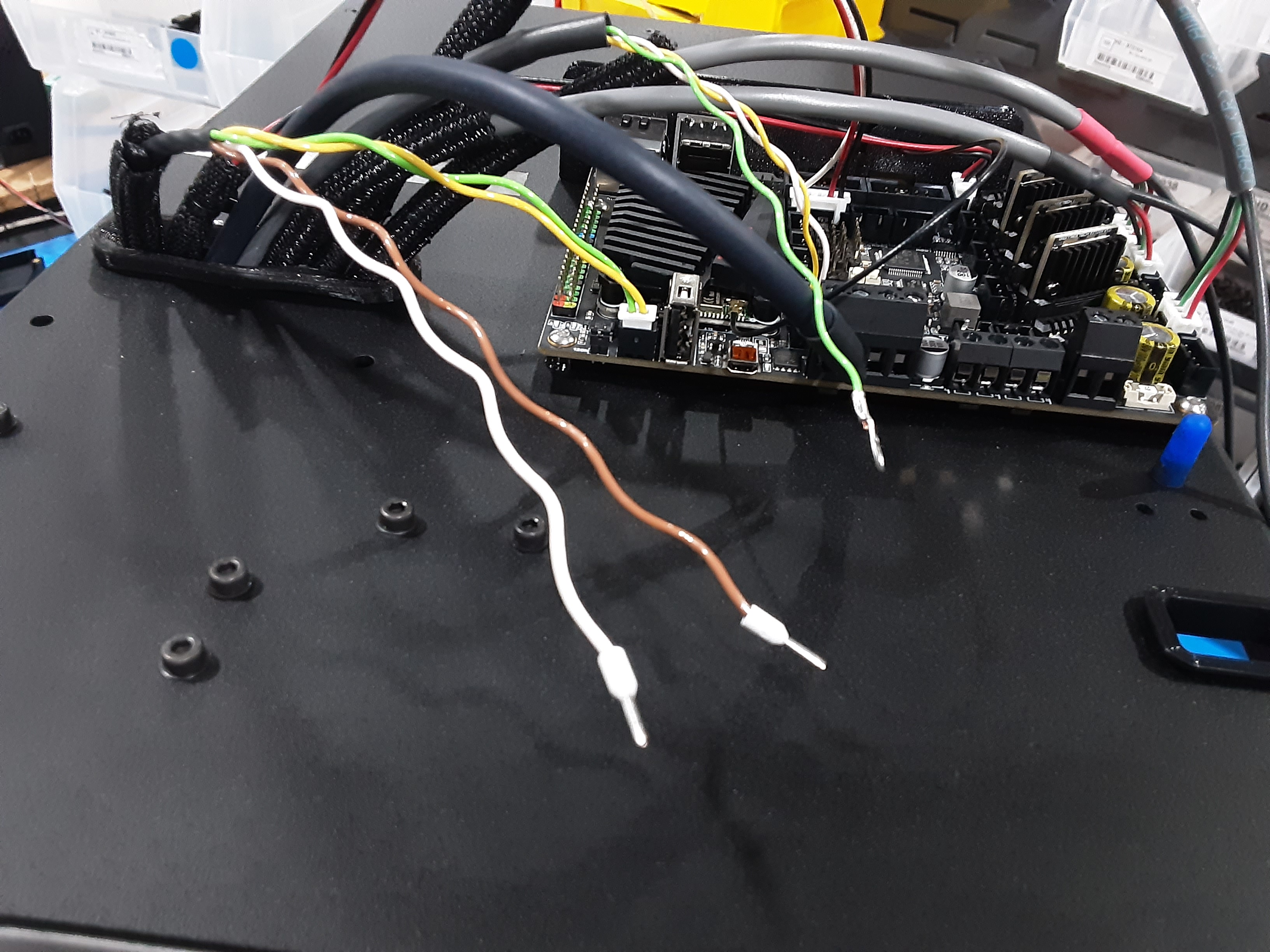
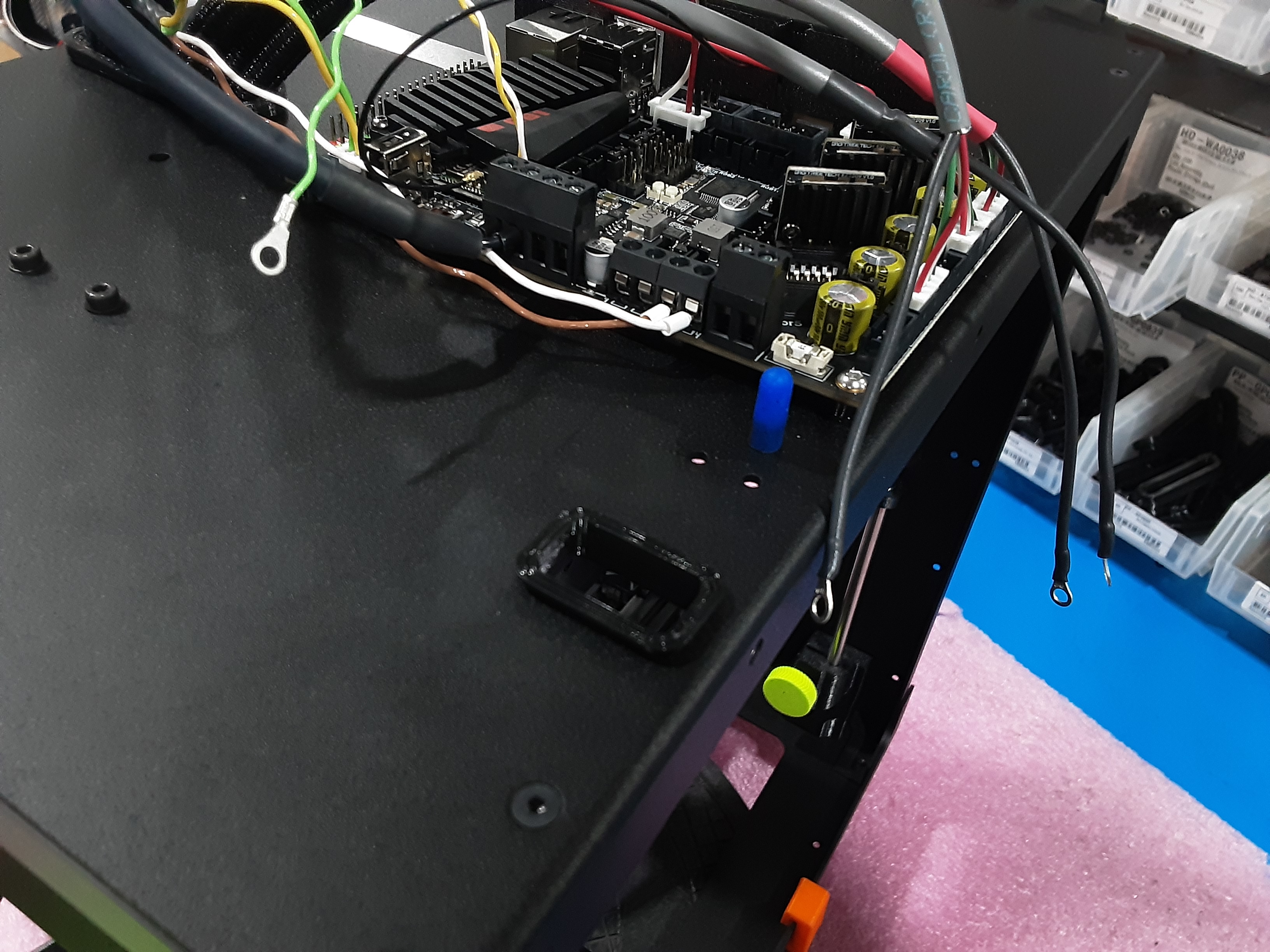
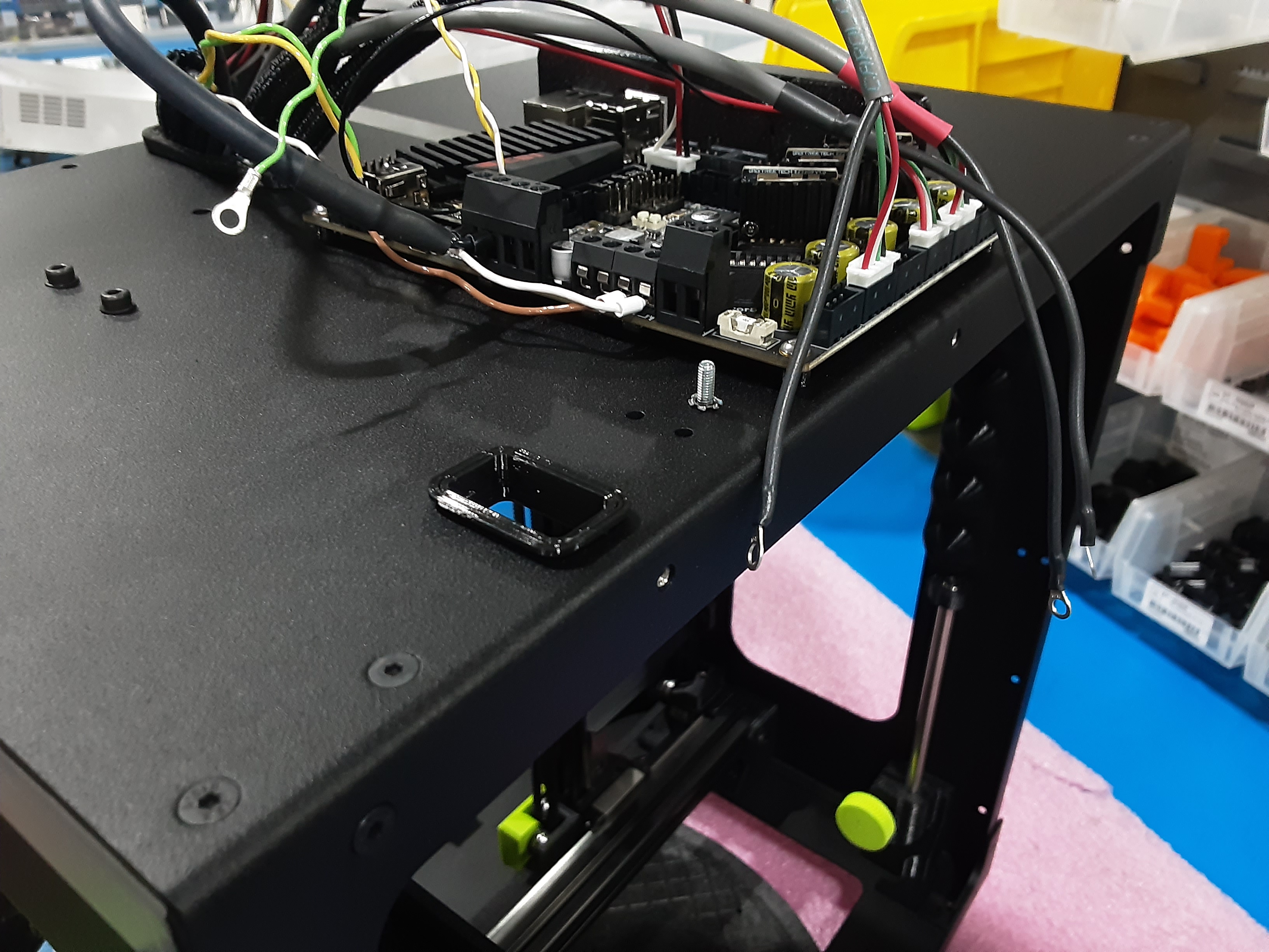
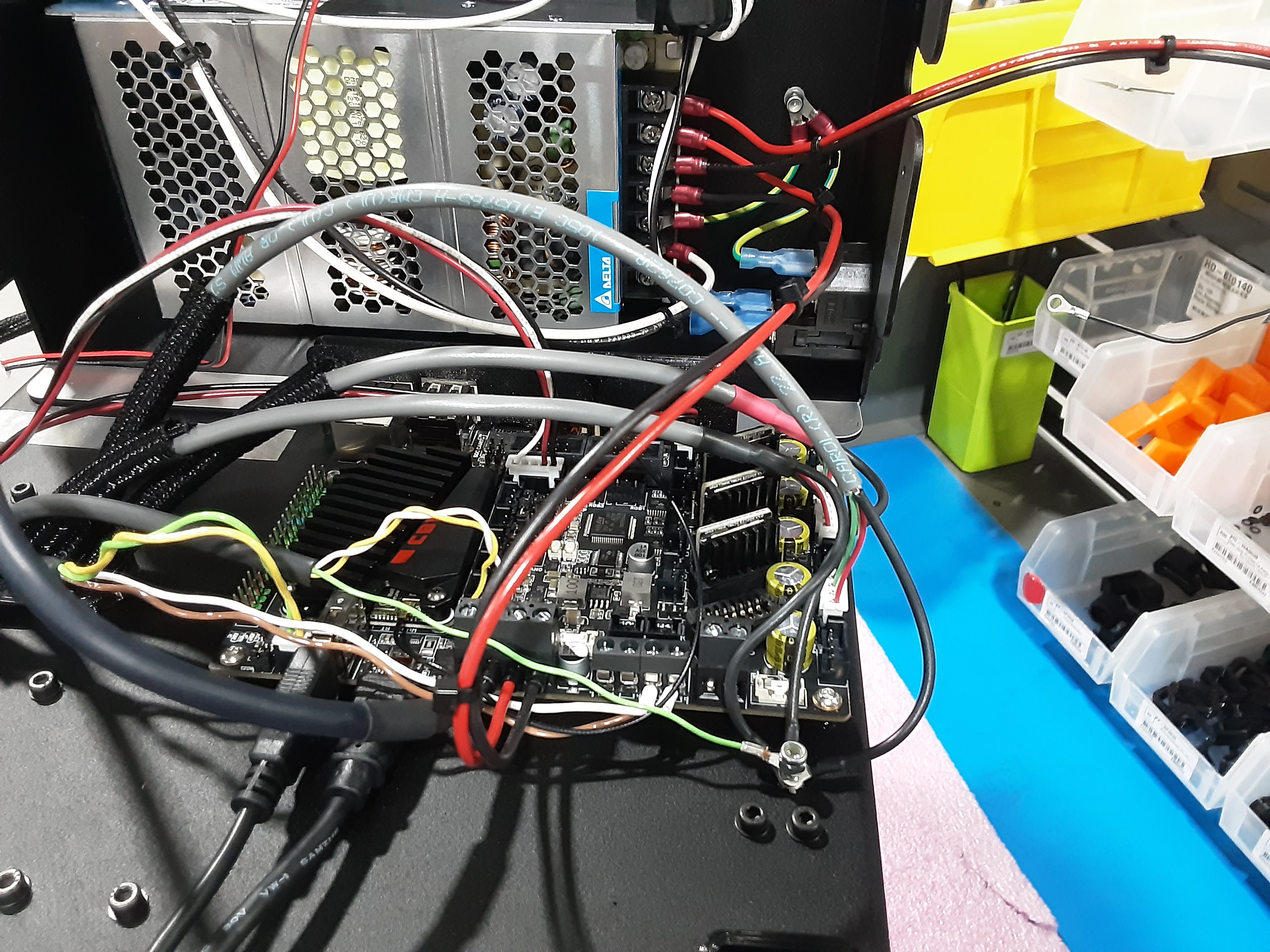
4M) Remove the blue cap from the ground screw and place HD-MS0035 x1 on it.
4N) Place the three ground wires from AS-CB0214 and the ground from the light grey wire from Y.A.B. on the ground screw and loosely attach HD-NT0001.
4O) Place PP-GP0891 over the wires on the inside of the F.A. making sure that the wires sit in the channels in PP-GP0891. Secure PP-GP0891 to the F.A. using HD-BT0157 x3 and HD-BT0038 x3.
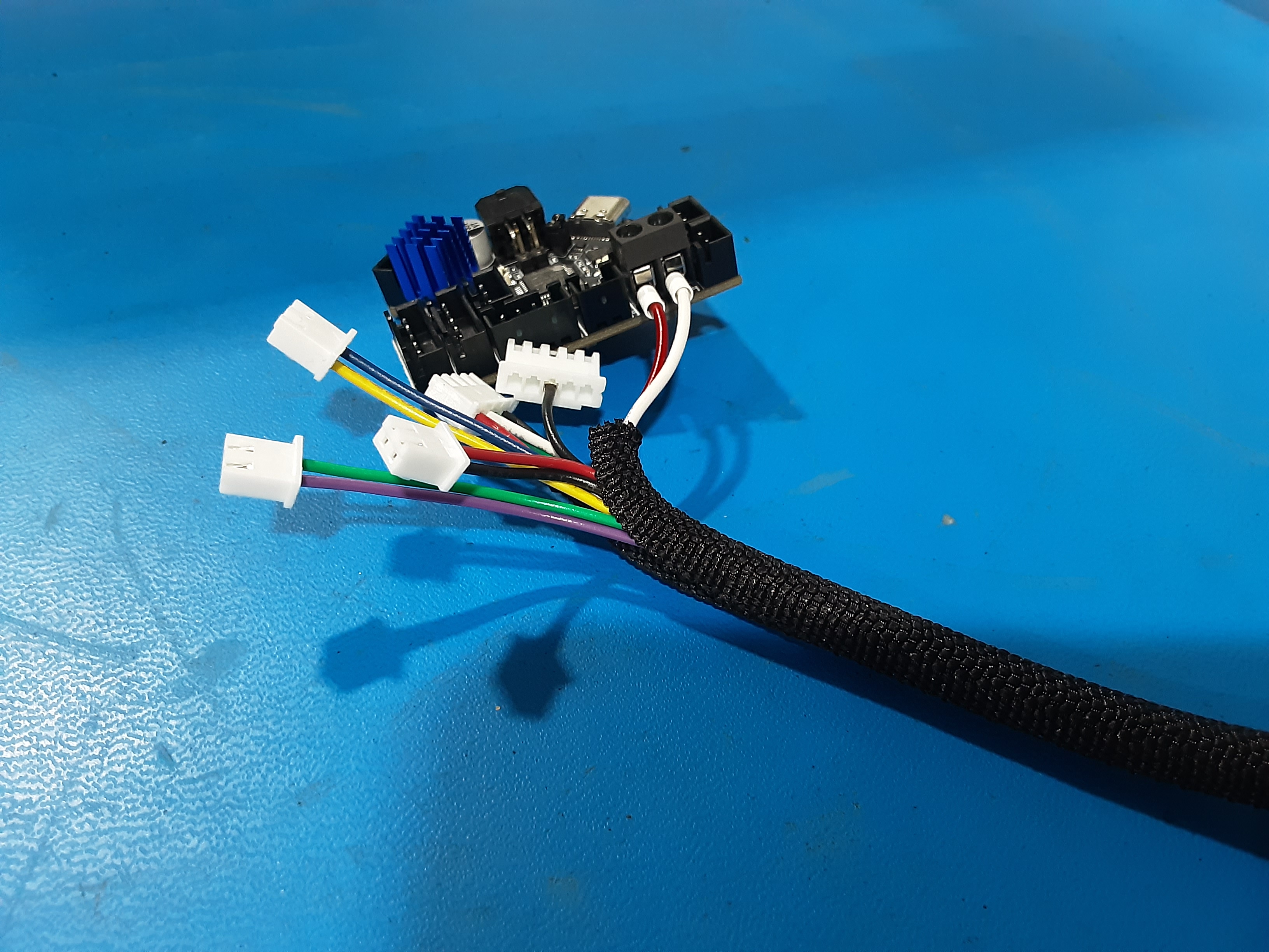
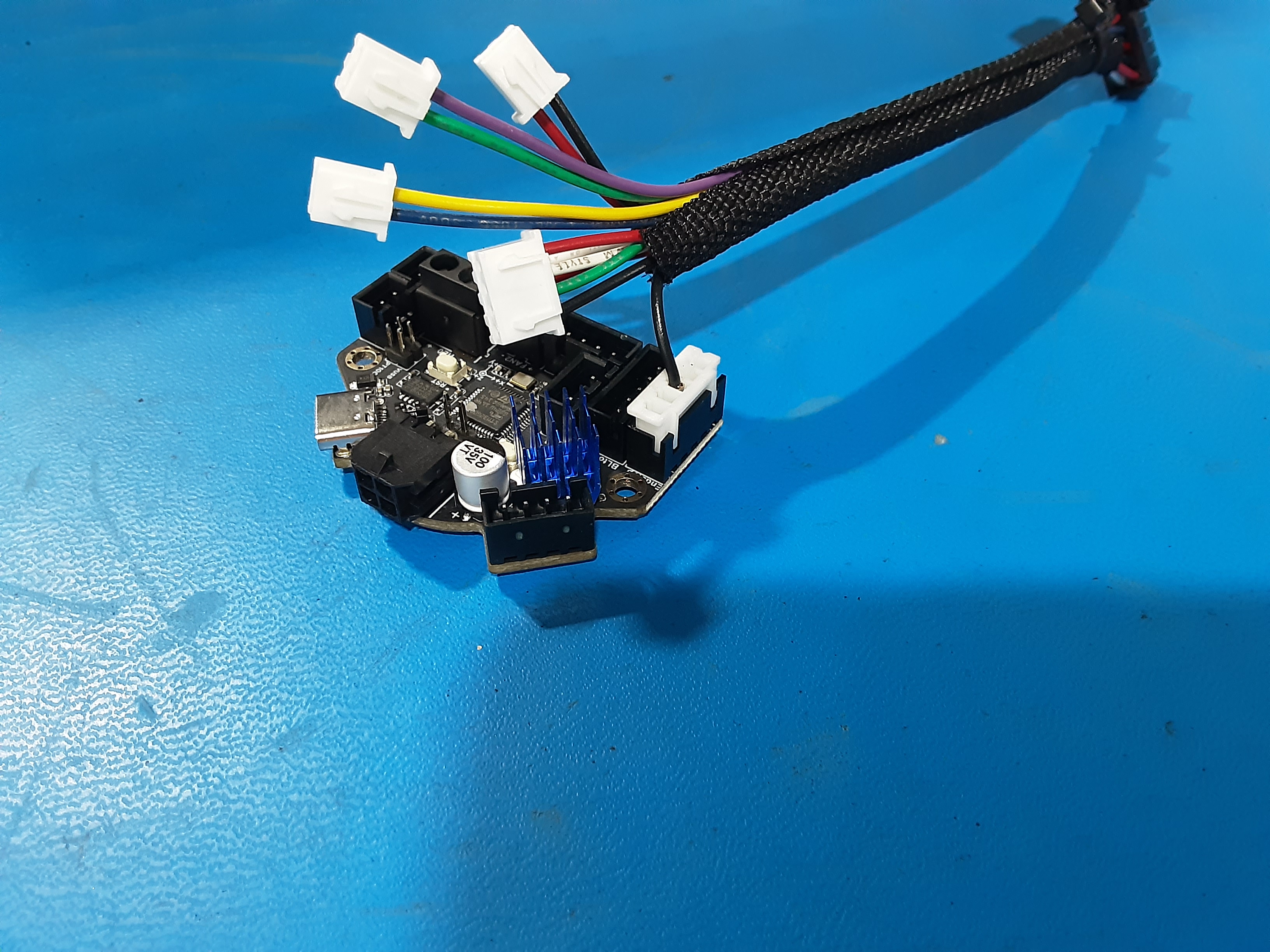
PC-BD0128 Assembly
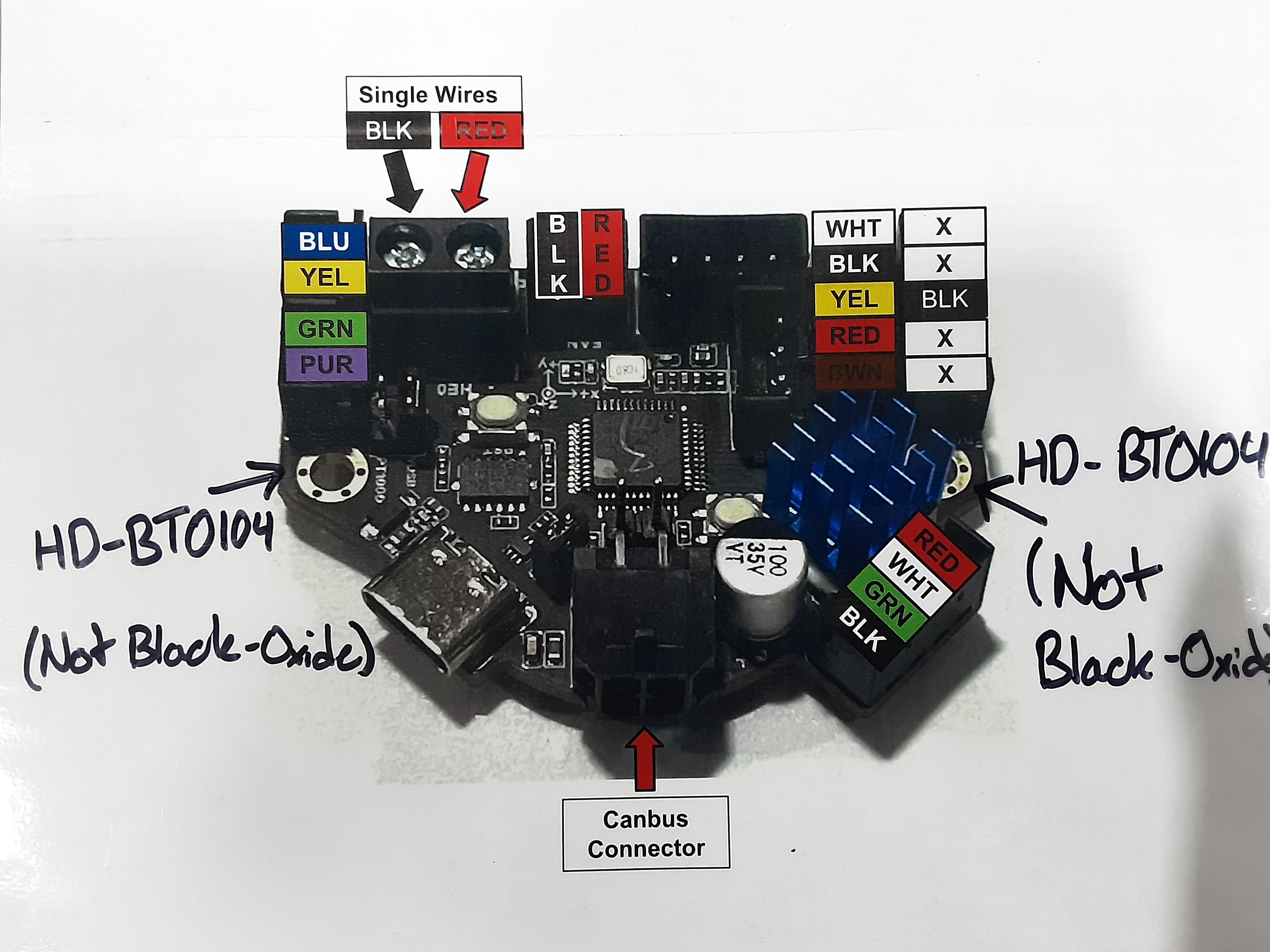
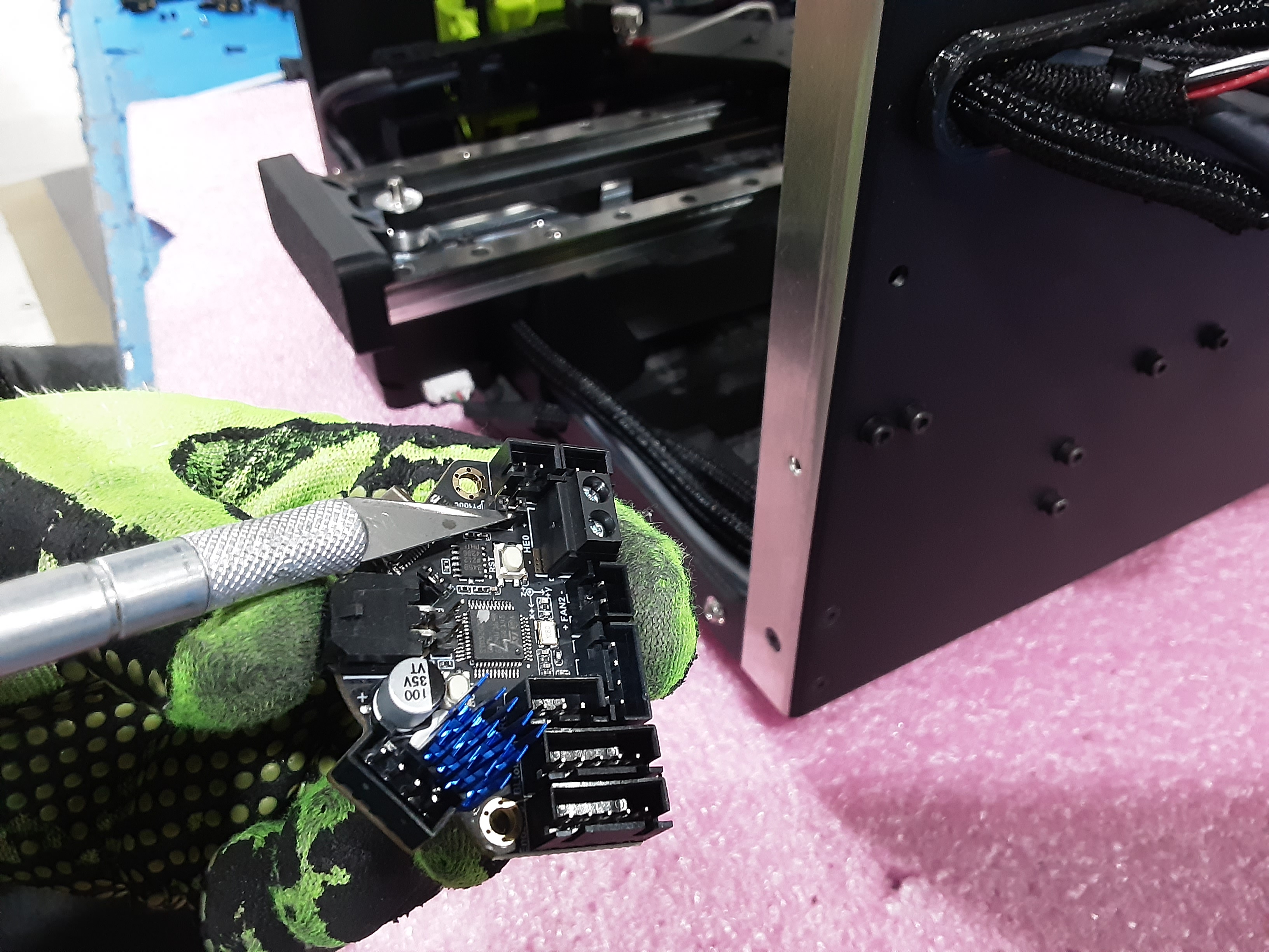
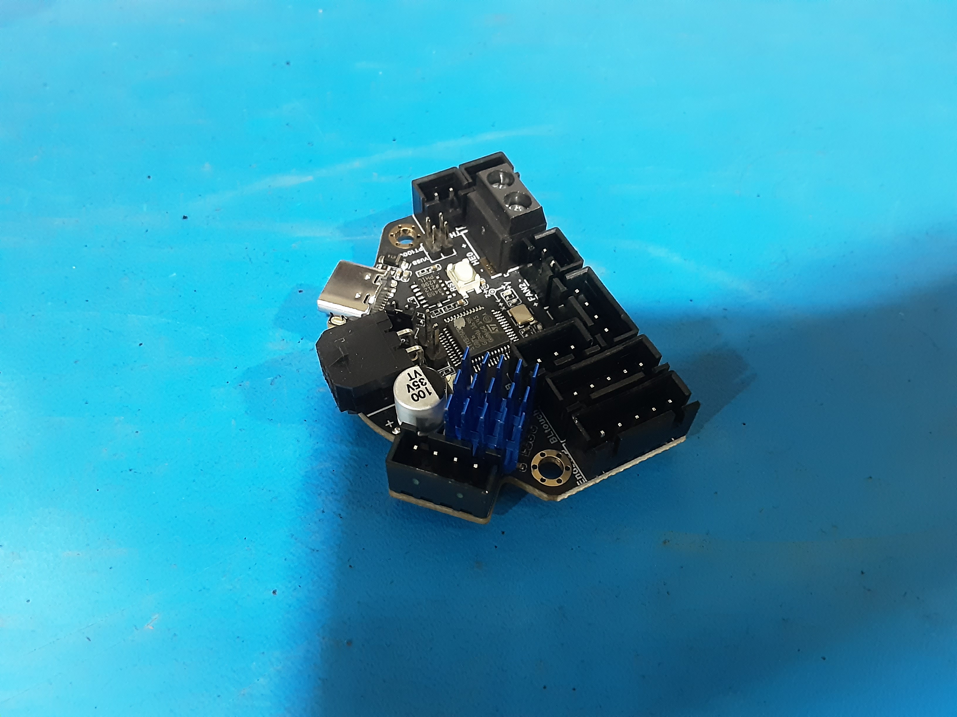
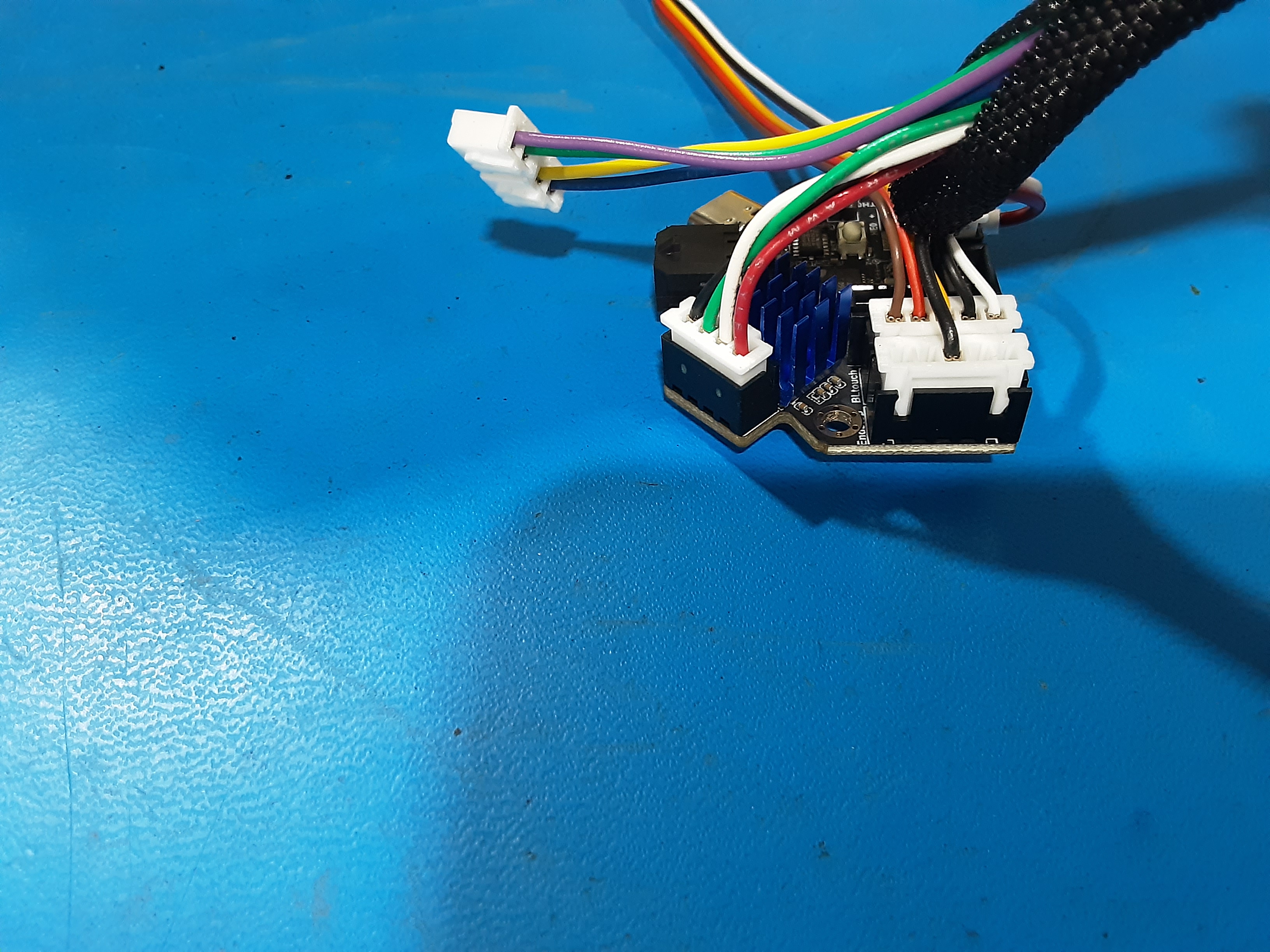
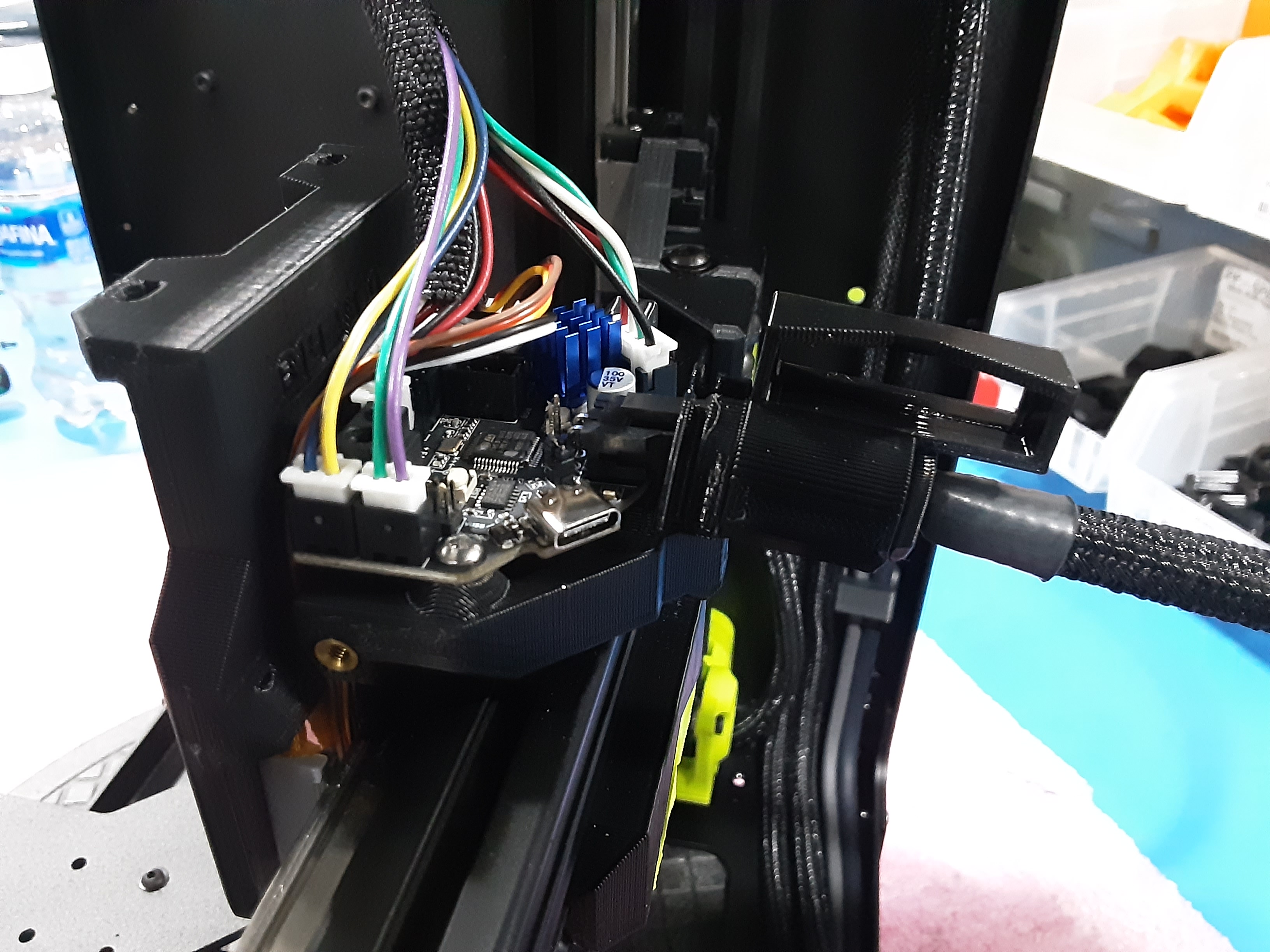
5A) Remove the black cover on PC-BD0128.
5B) Loosen the shown clamp screws on PC-BD0128. With the longer flat side of the terminals on
EL-HR0212 facing the screw head insert the terminals into the correct clamps. Tighten the screws to secure the wires.
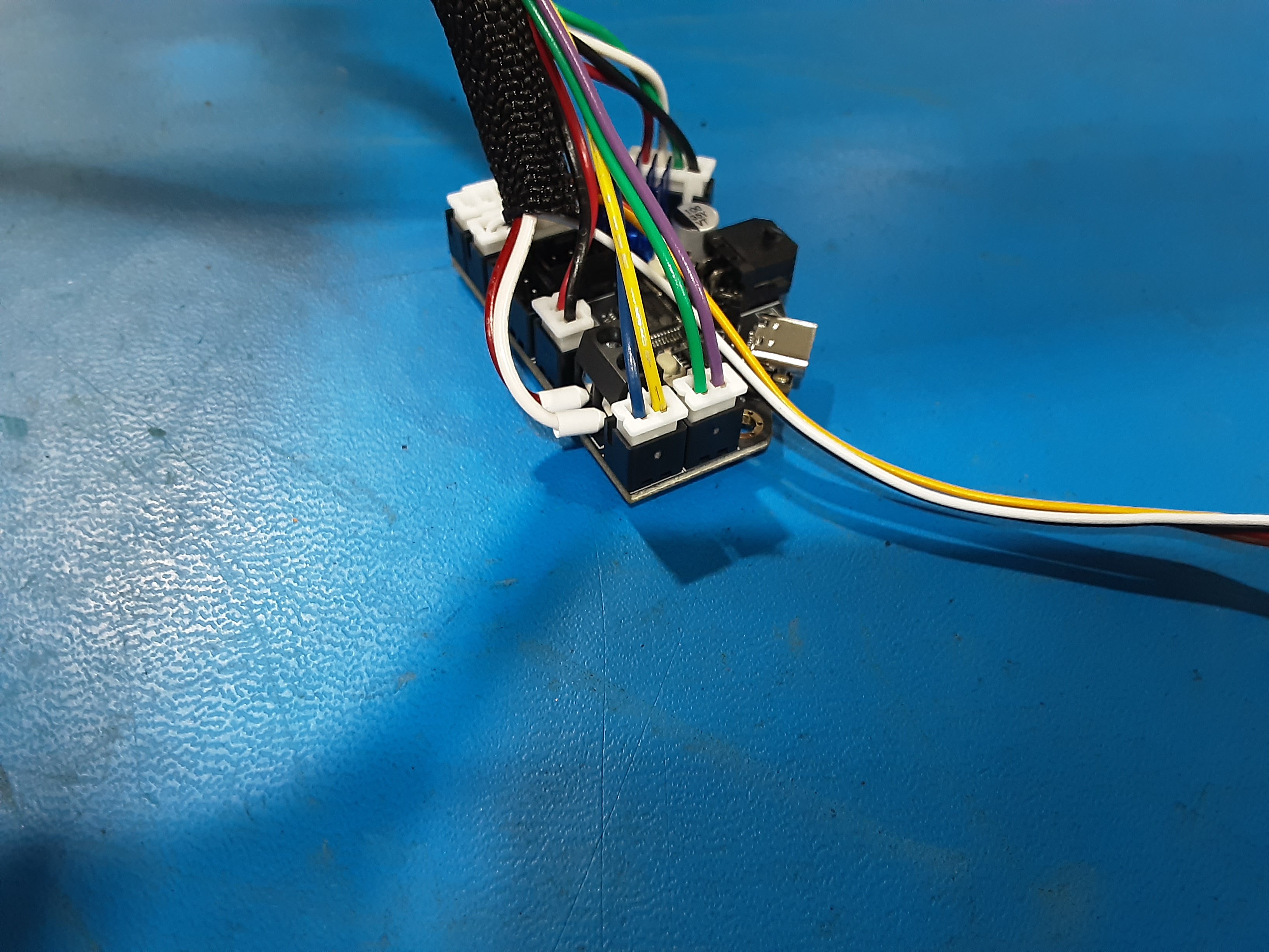
5C) Plug in the single black wire connector into PC-BD0128 where shown.
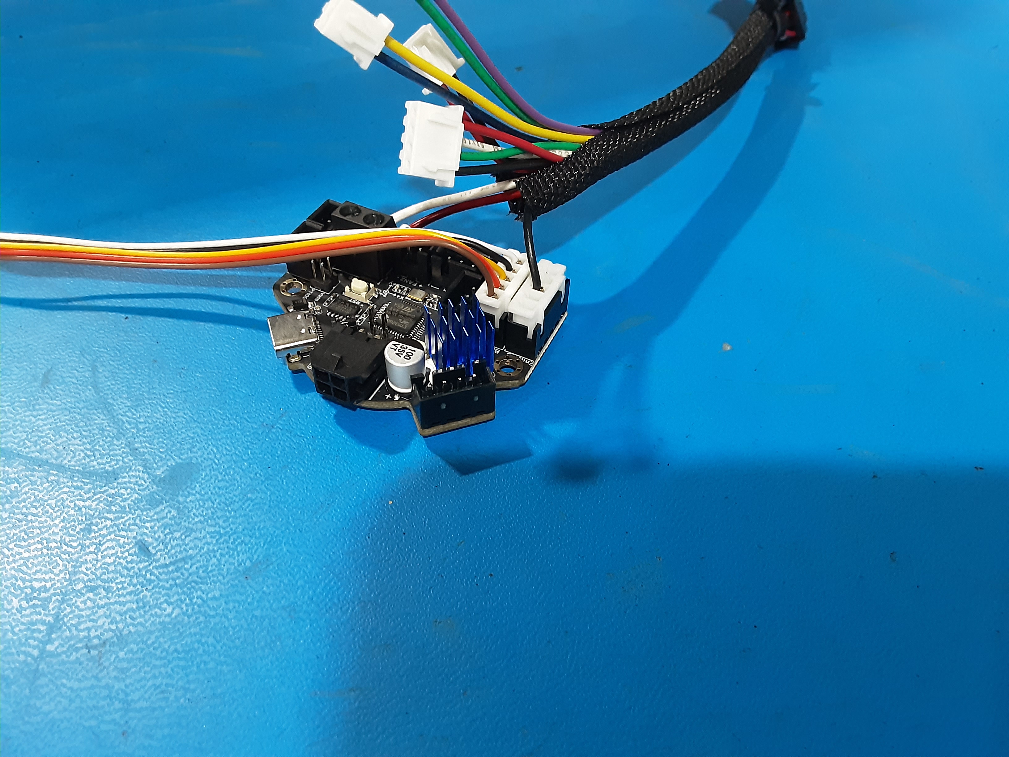
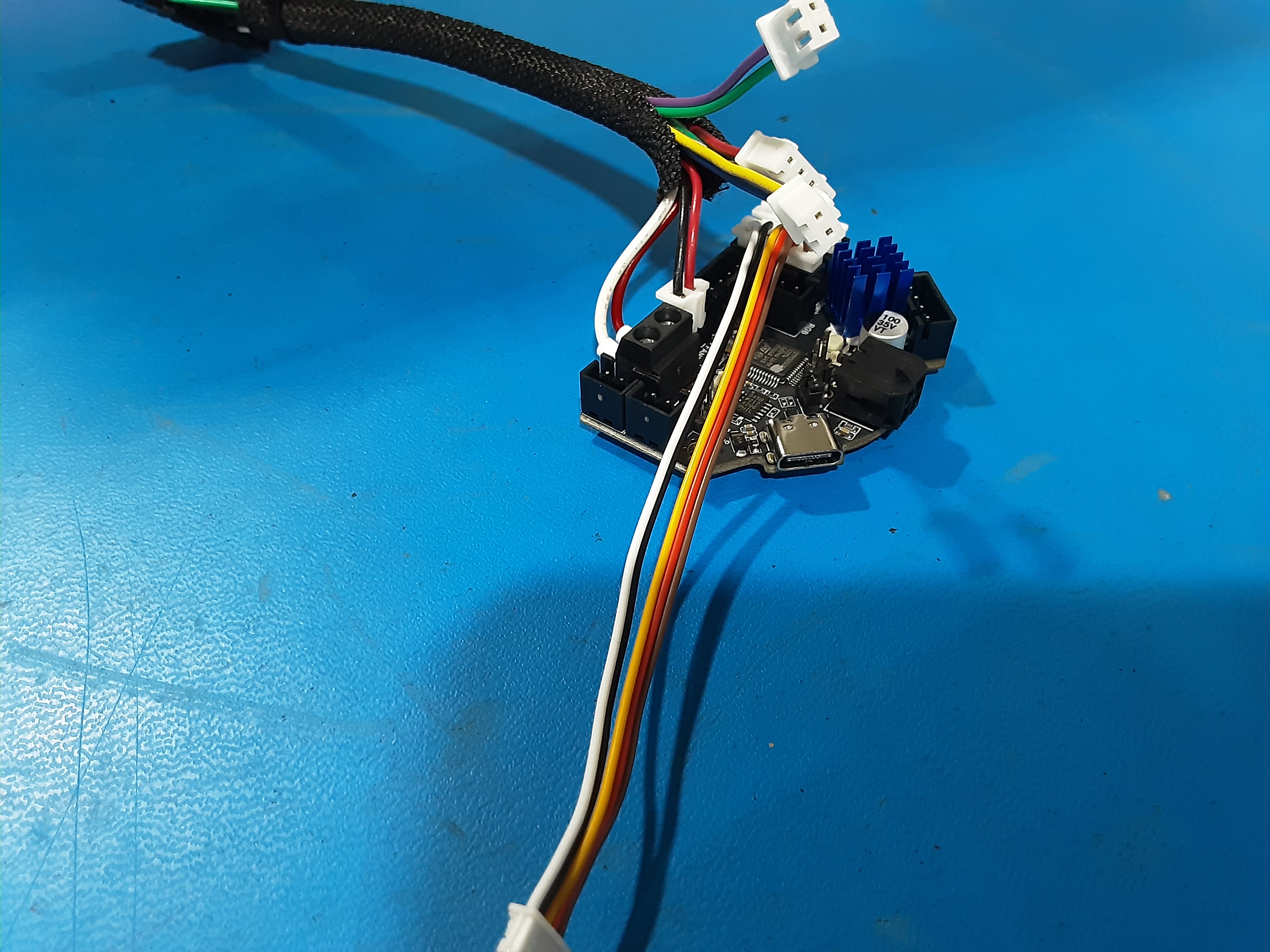
5D) Grab EL-HR0213 and plug in the bigger connector into PC-BD0128 where shown.
5E) Plug in the rest of the connectors from EL-HR0212 into PC-BD0128 where shown.
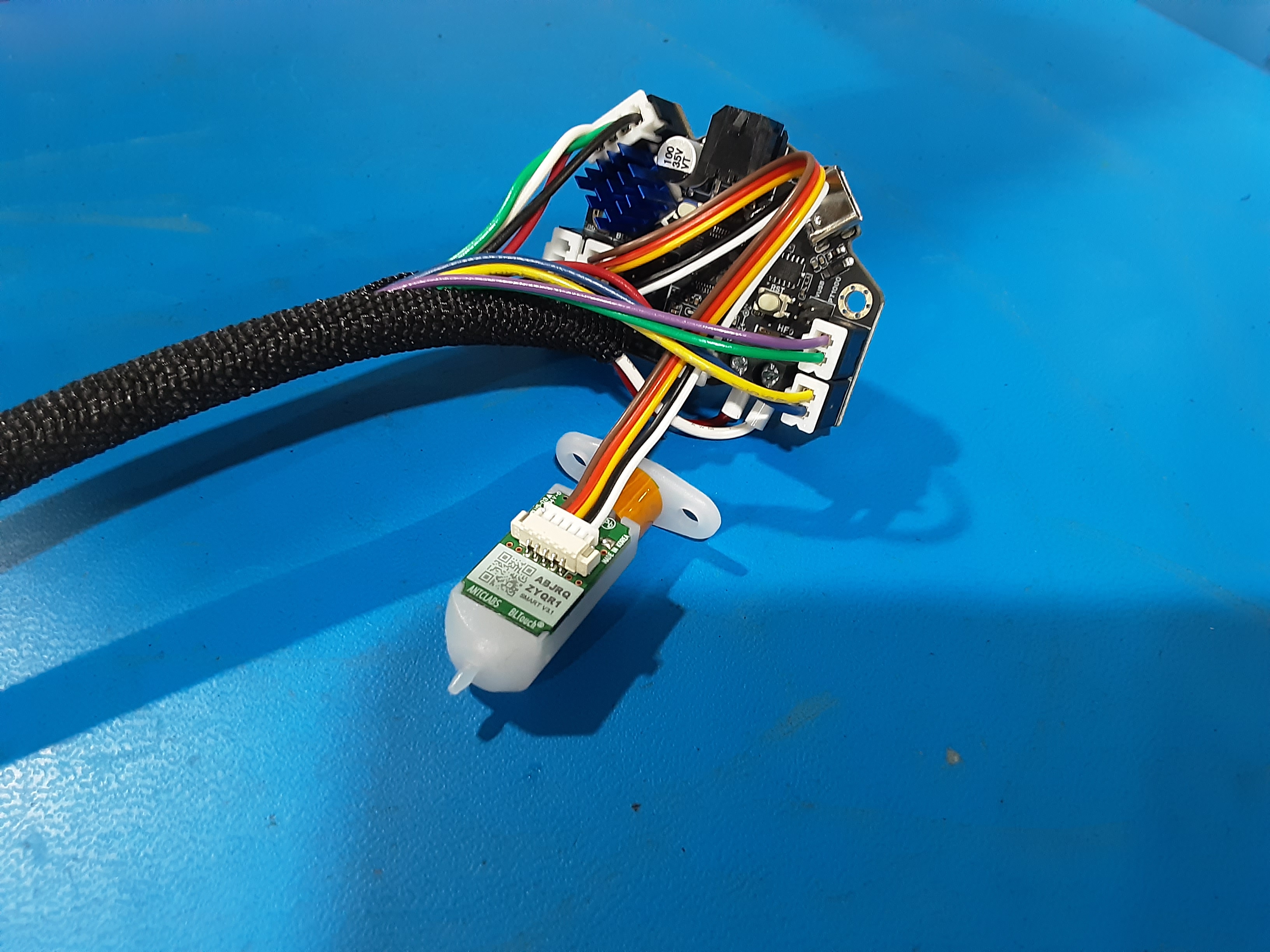
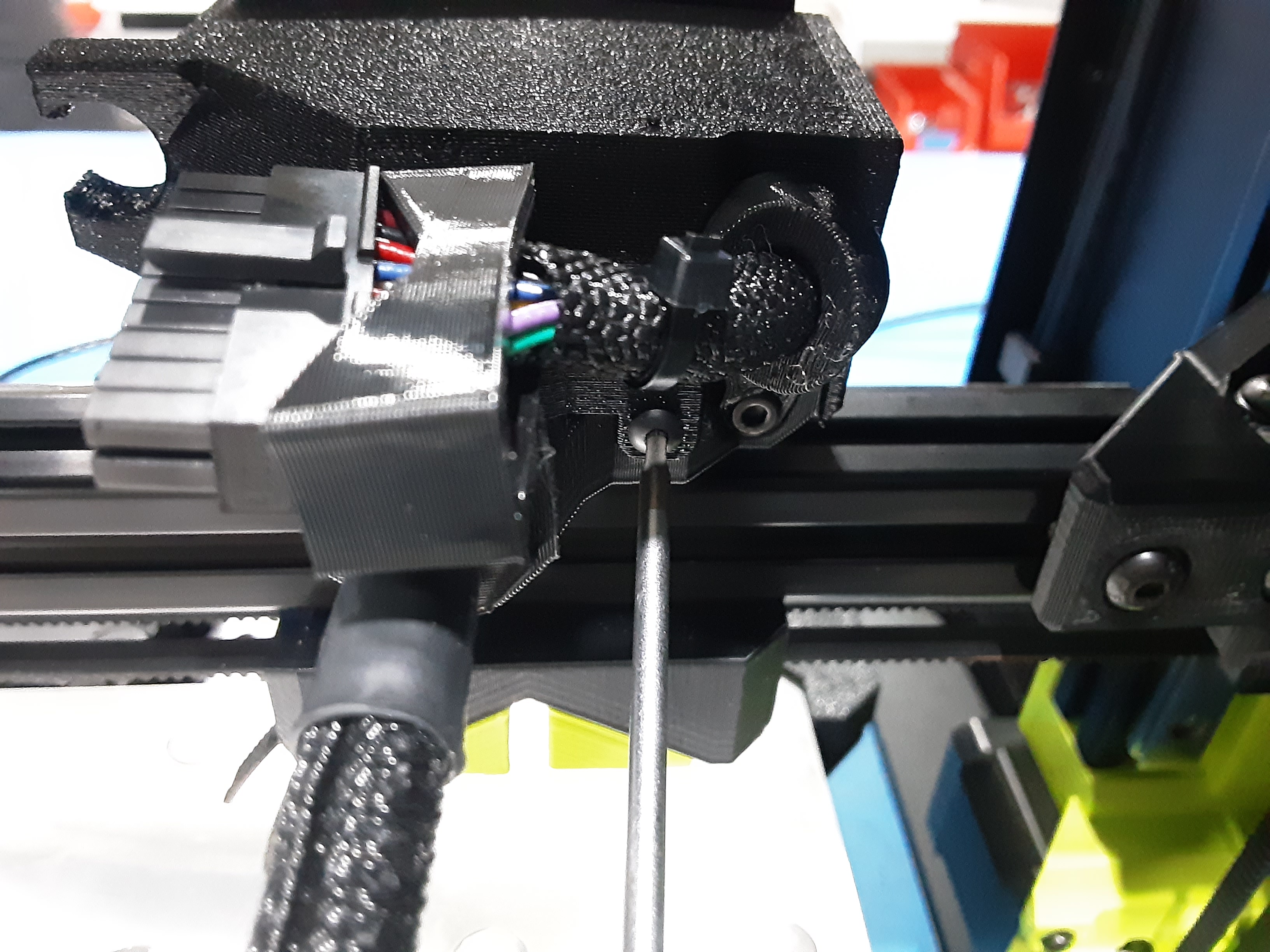
5F) Route EL-HR0213 under the purple / green and yellow / blue wires and plug into PP-MP0237.
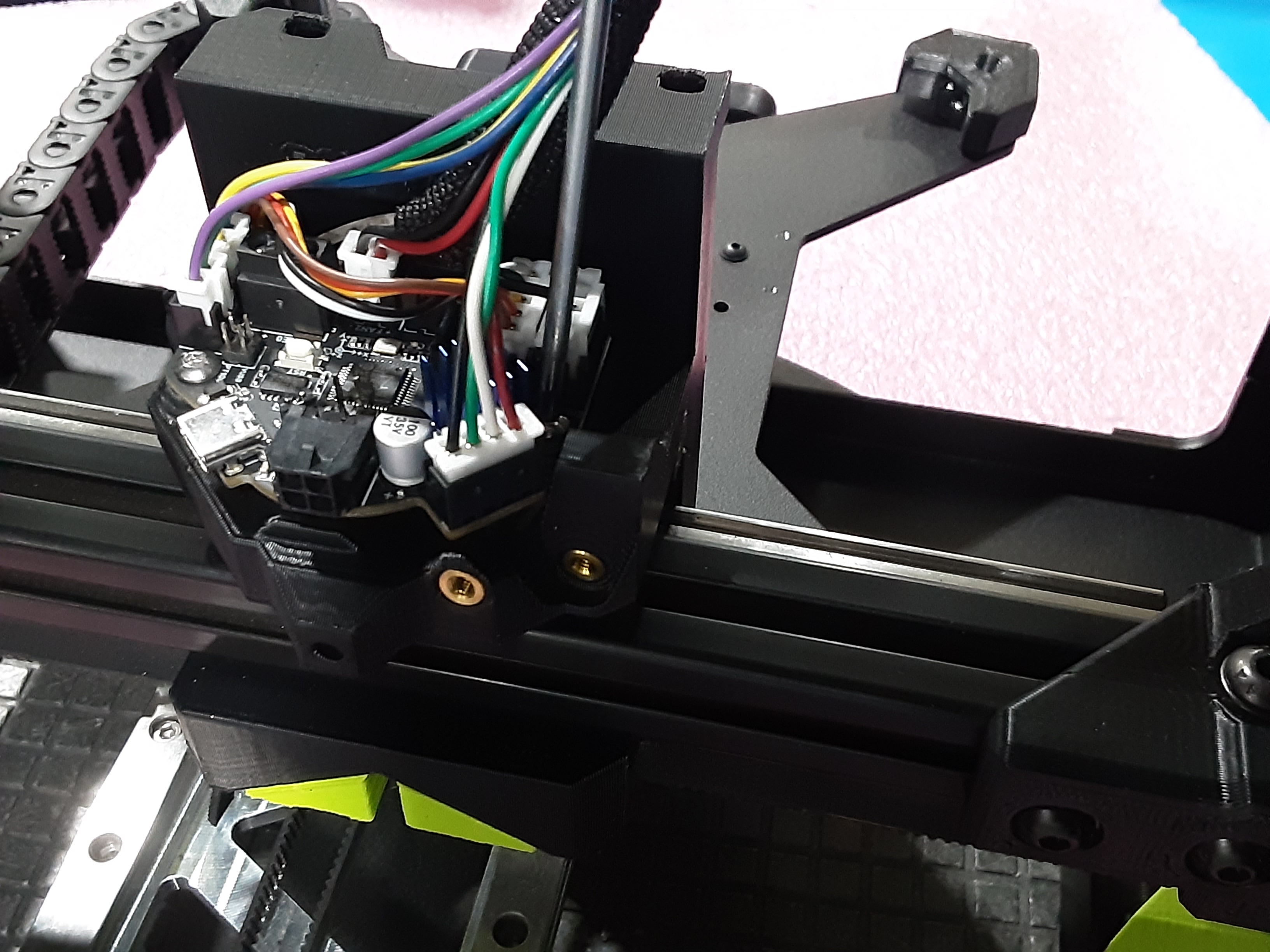
5G) Line up and attach PC-BD0128 to PP-GP0814 from X.C.A. using HD-BT0104 x2.
5H) Attach PP-MP0327 to PP-GP0814 using HD-BT0045 x2 in shown orientation.
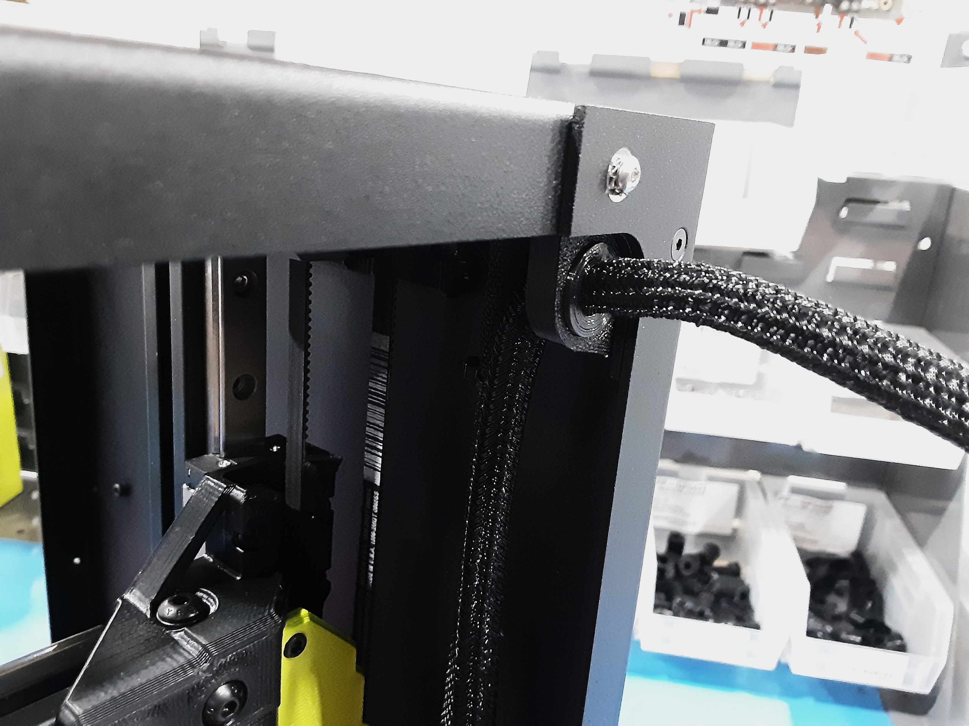
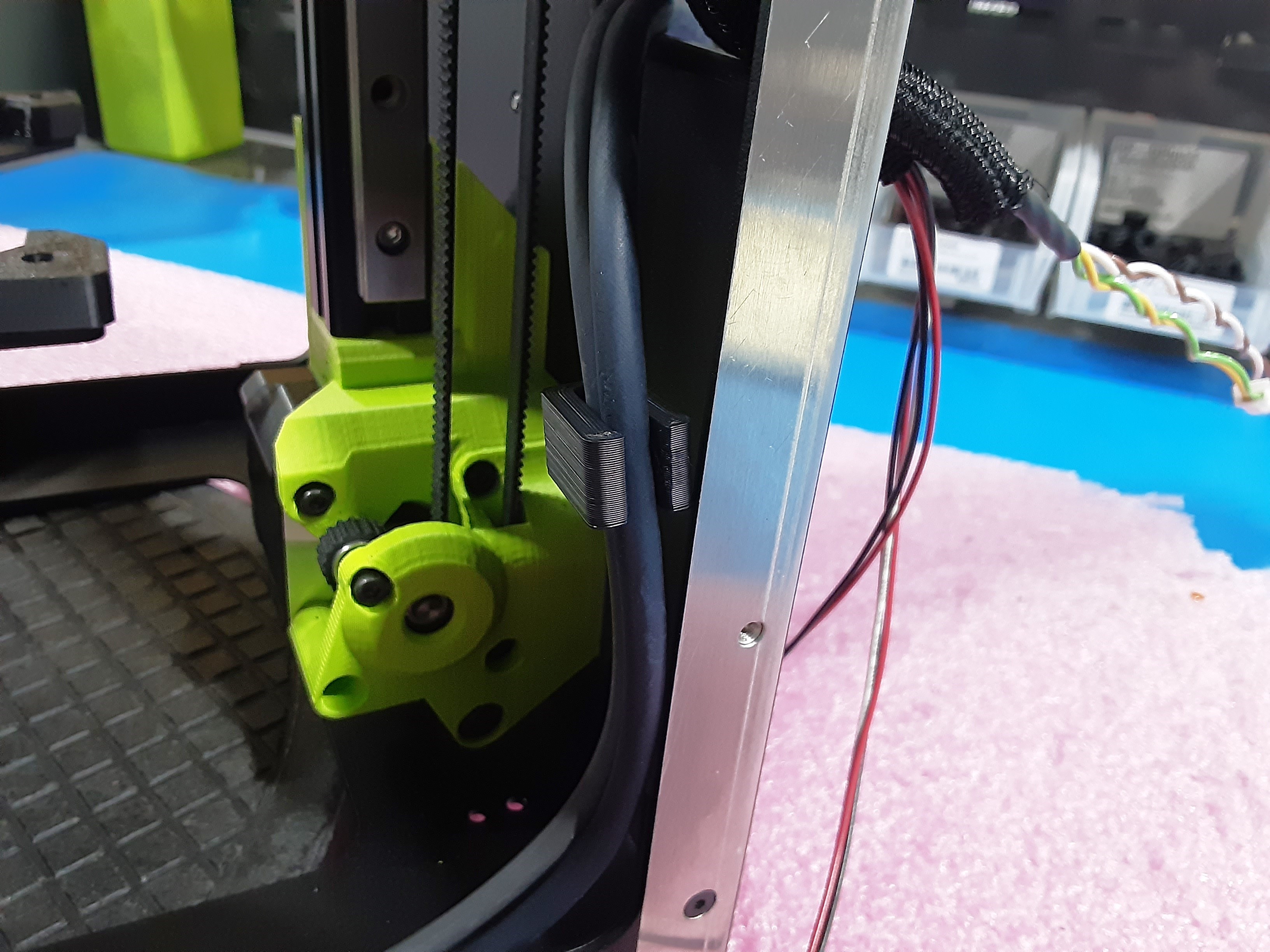
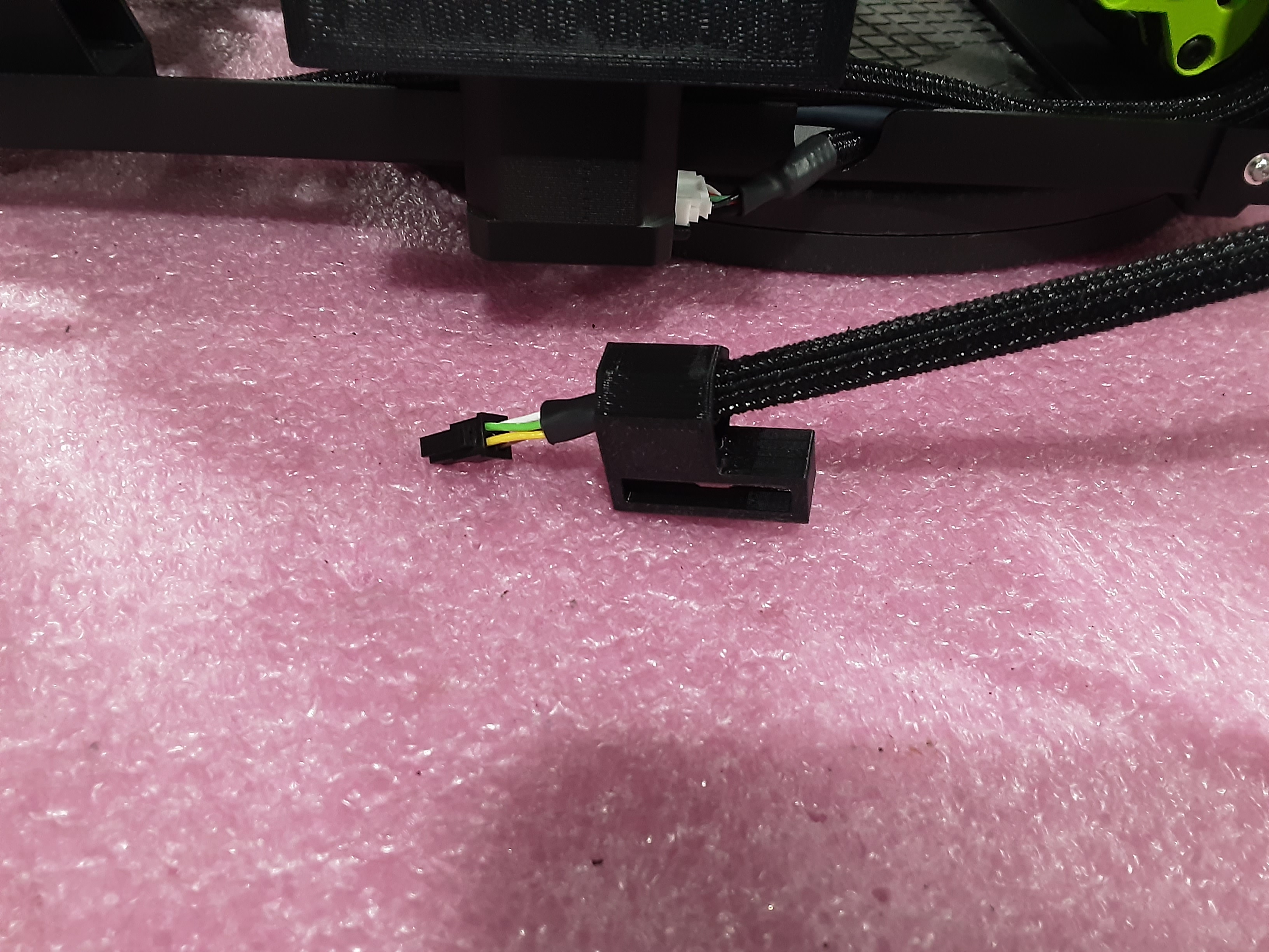
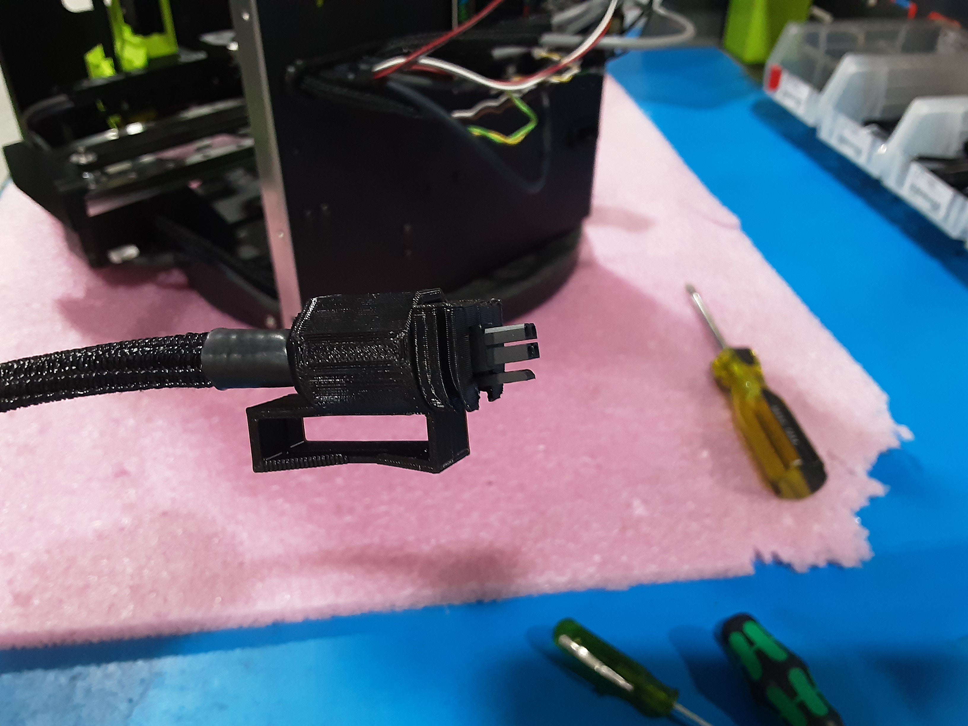
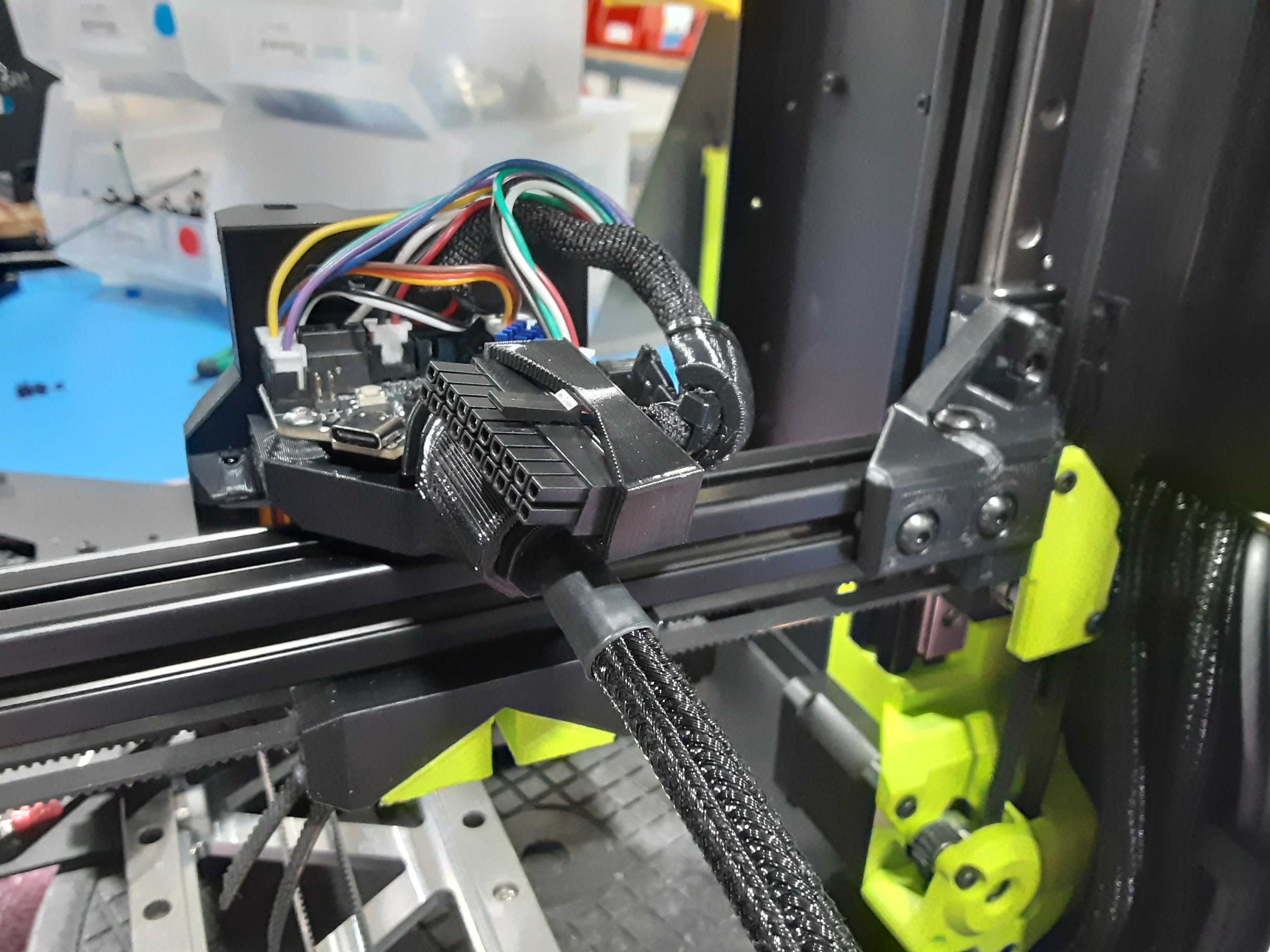
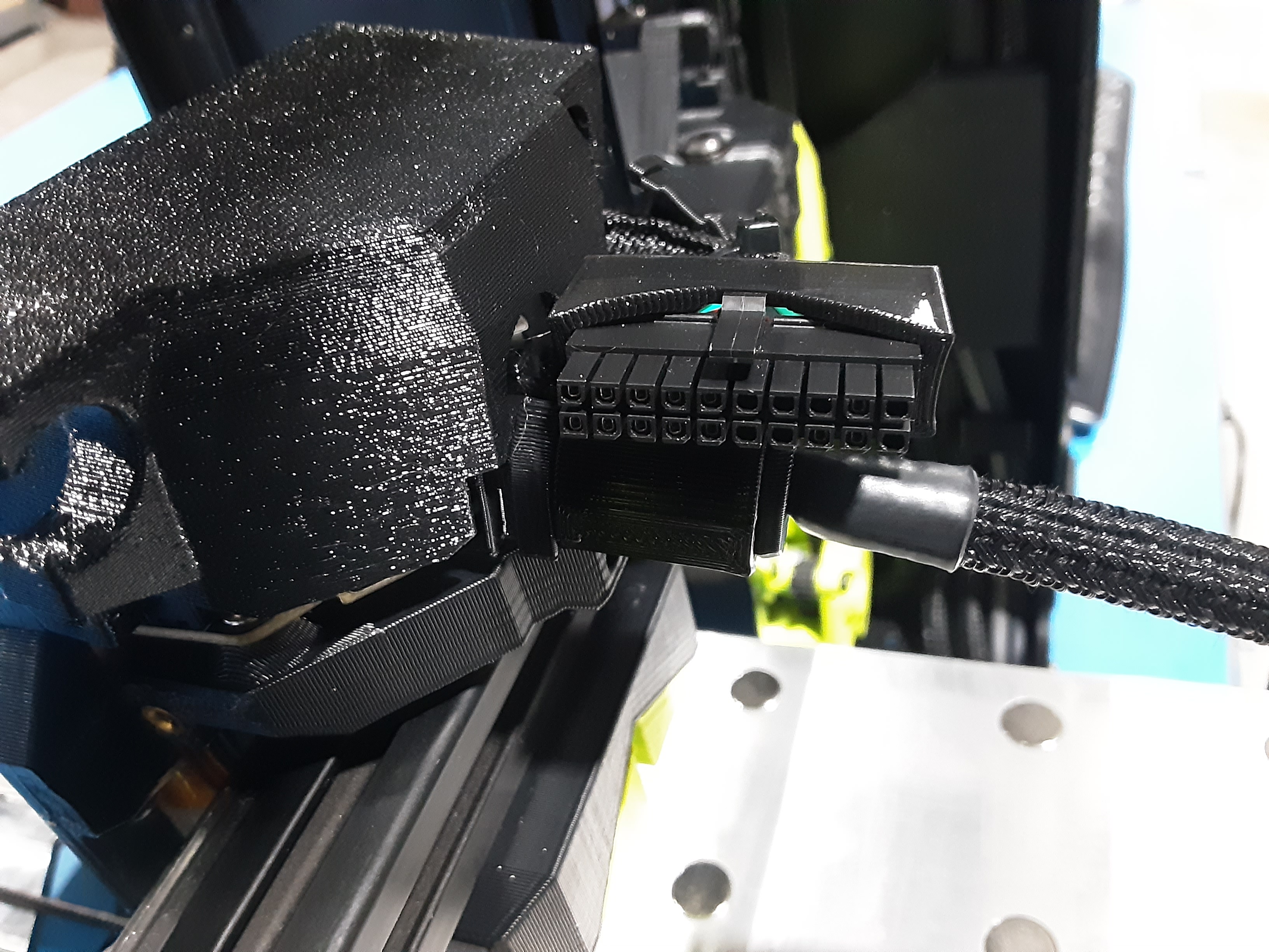
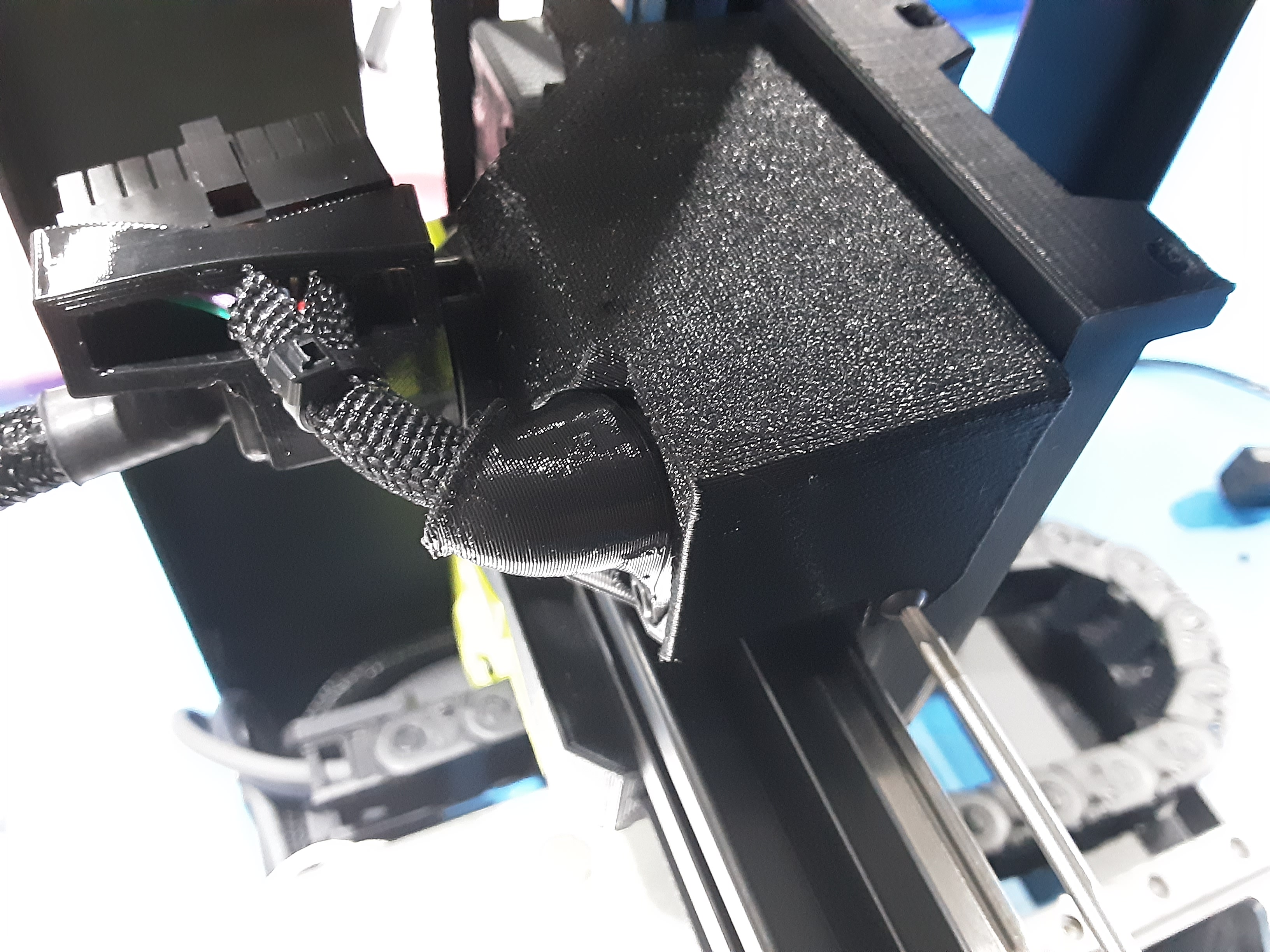
5I) Slide PP-GP0938 onto AS-CB0212 as shown.
5J) Slide PP-GP0831 onto AS-CB0212 and insert it in PP-GP0938 as shown.
5K) Plug AS-CB0212 into PC-BD0128.
5L) Put PP-GP0834 on EL-HR0212 as shown.
5M) Attach PP-GP0834 to PP-GP0814 using HD-BT0157 x1.
5N) Insert connector from EL-HR0212 into PP-GP0938.
5O) Line up and slide PP-GP0815 into the channel on PP-GP0831 over PC-BD0128.
5P) Attach PP-GP0815 to PP-GP0814 using HD-BT0140 x3.
Attach S.A.
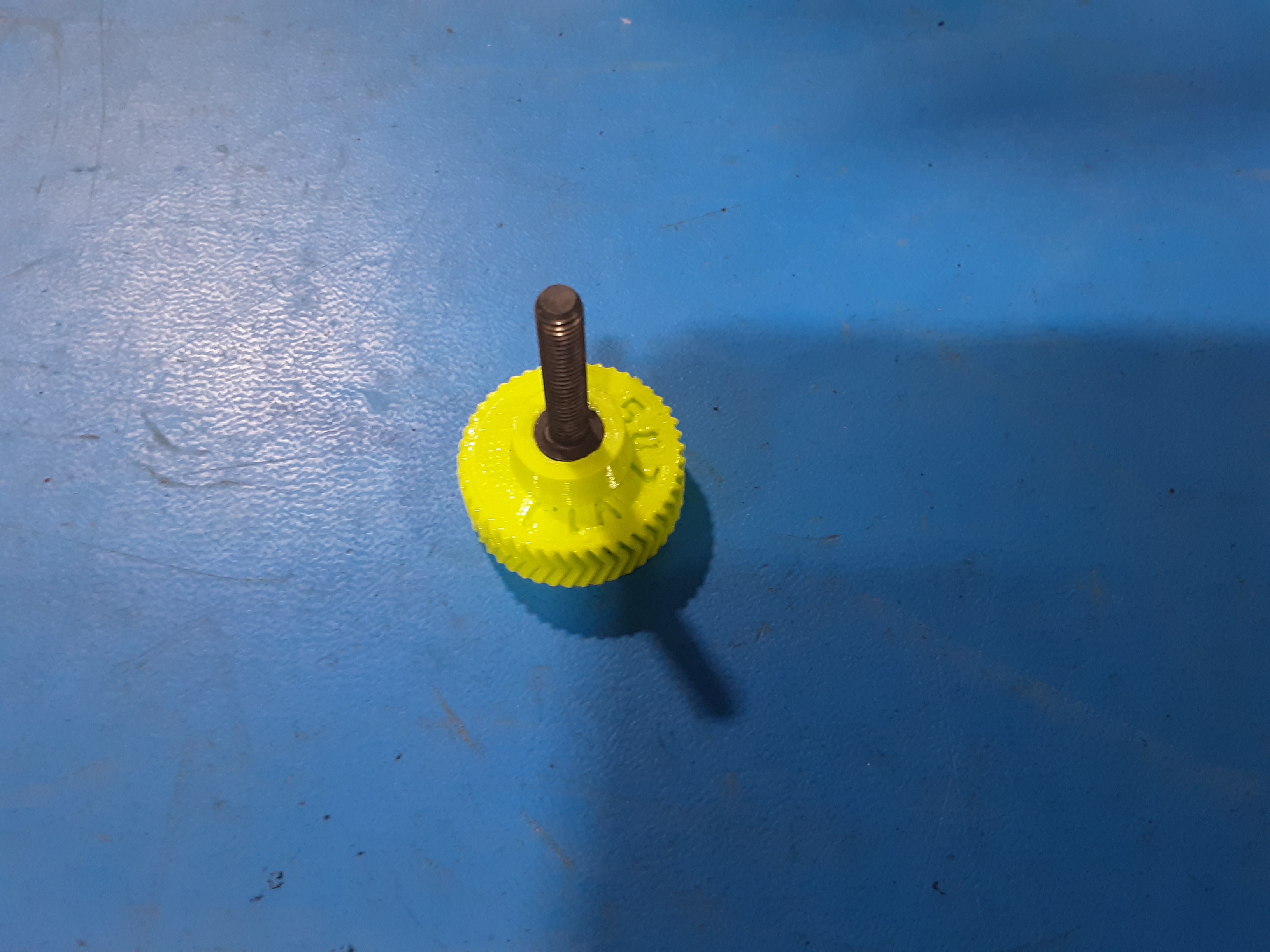
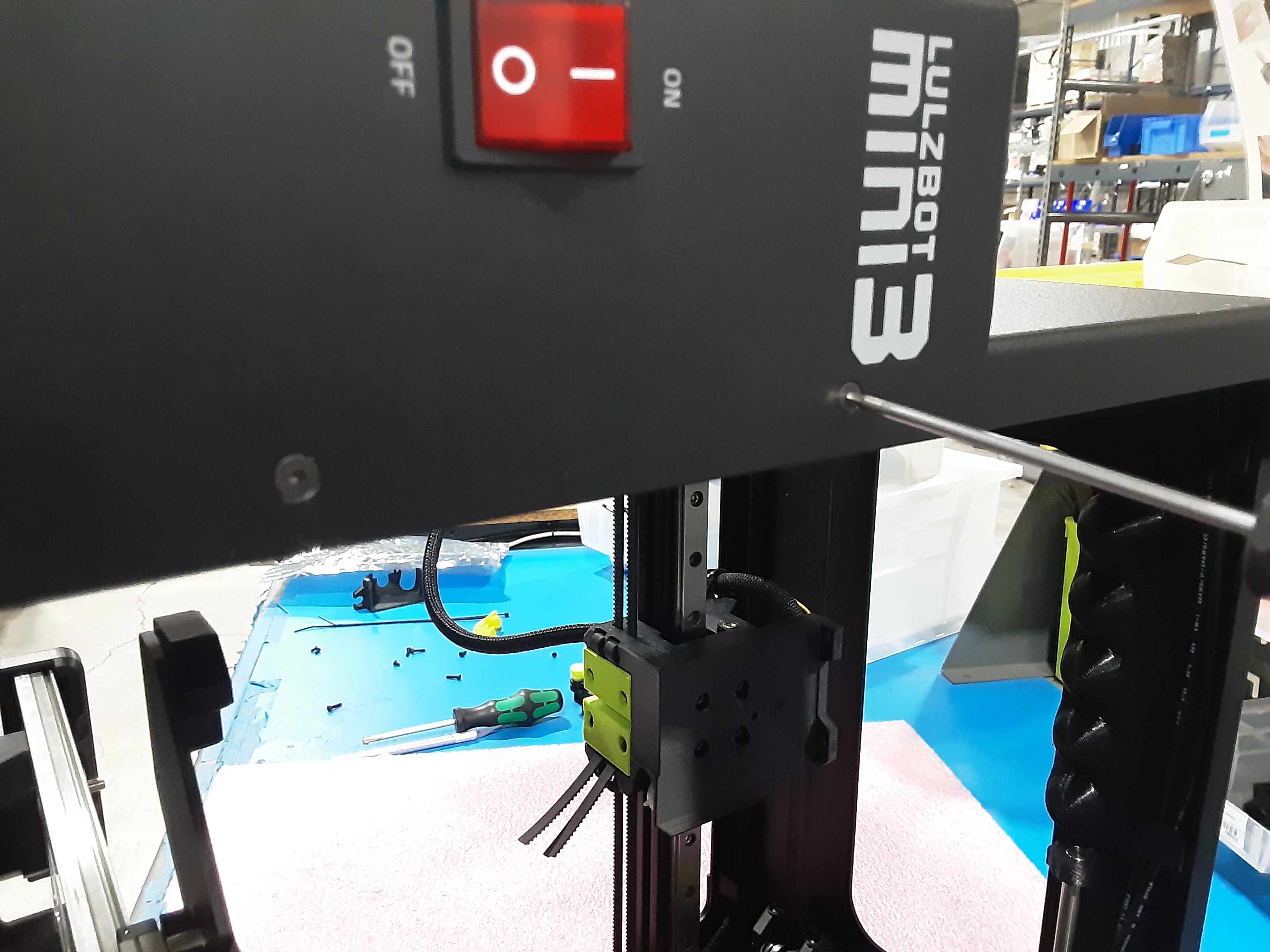
6A) Remove PP-GP0587 knob from F.A.
6B) Attach the S.A. to the F.A. using HD-BT0128 x3
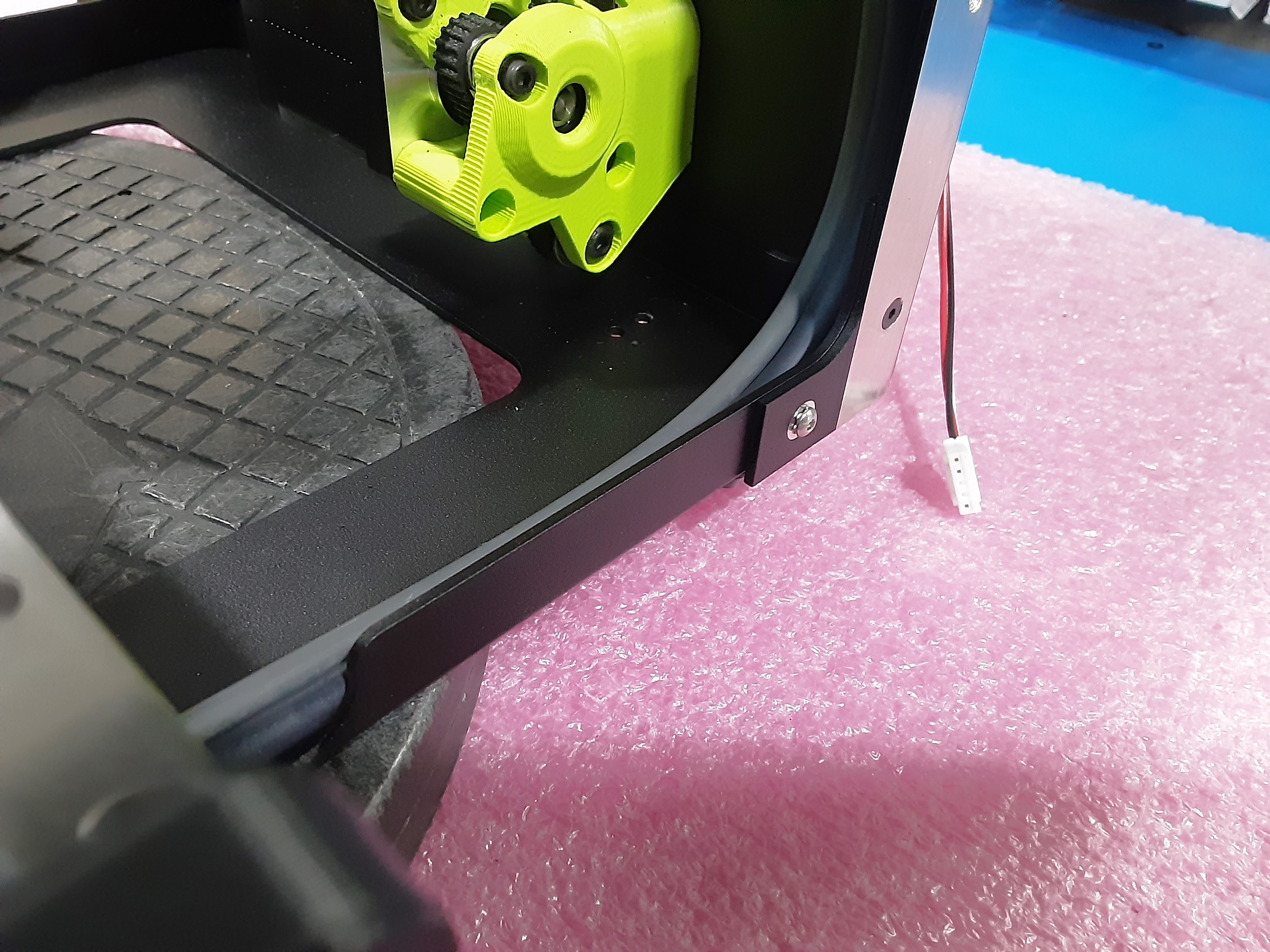
6C) Feed the two wires that came with the S.A. through PP-GP0839 as shown.
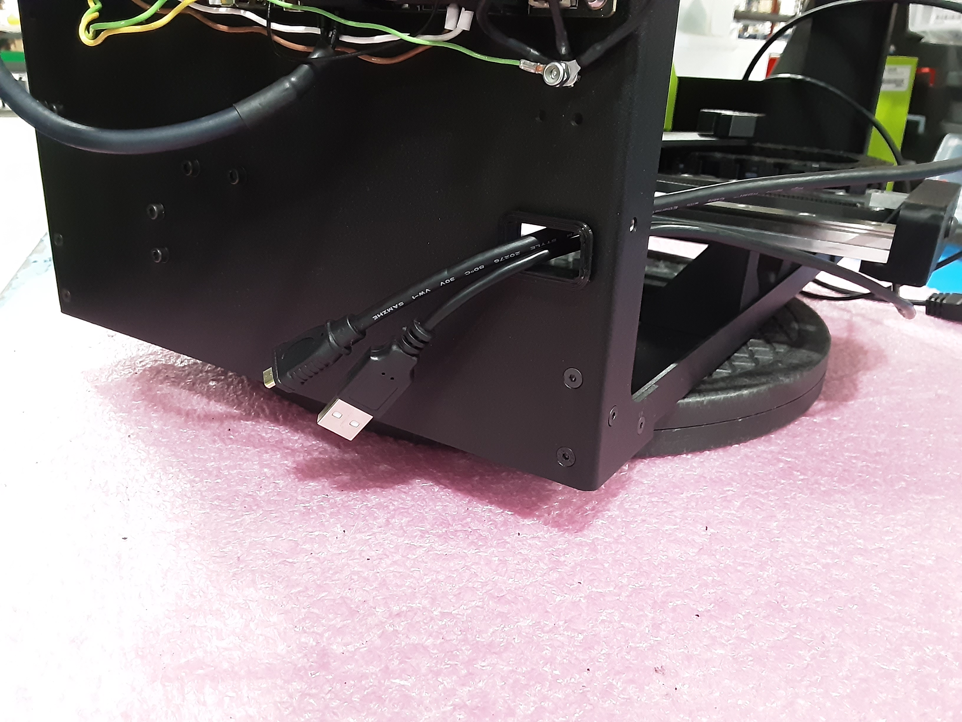
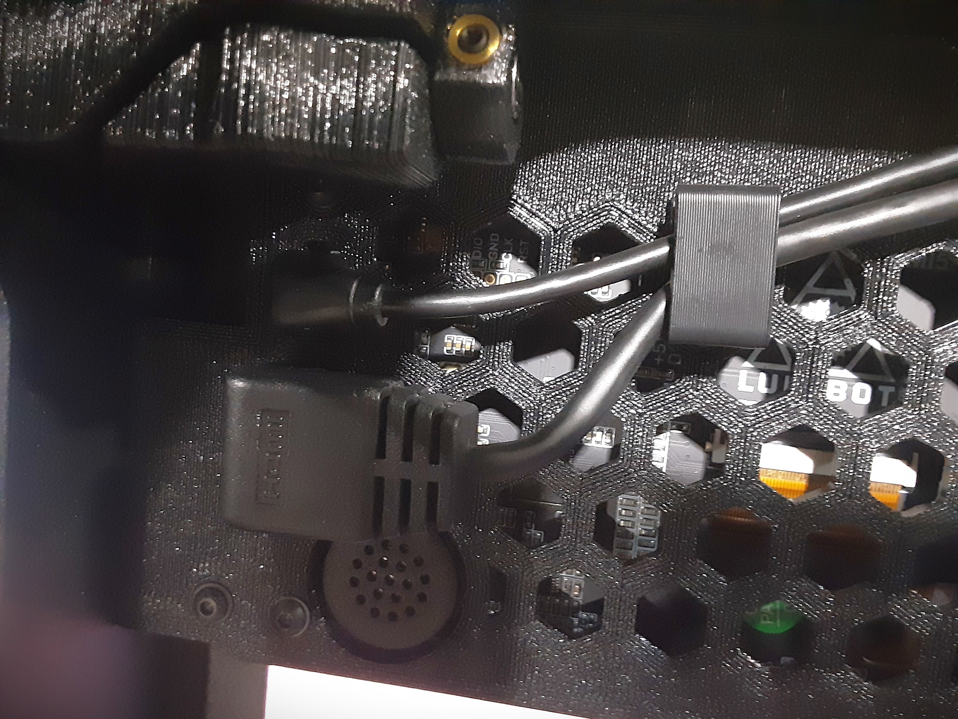
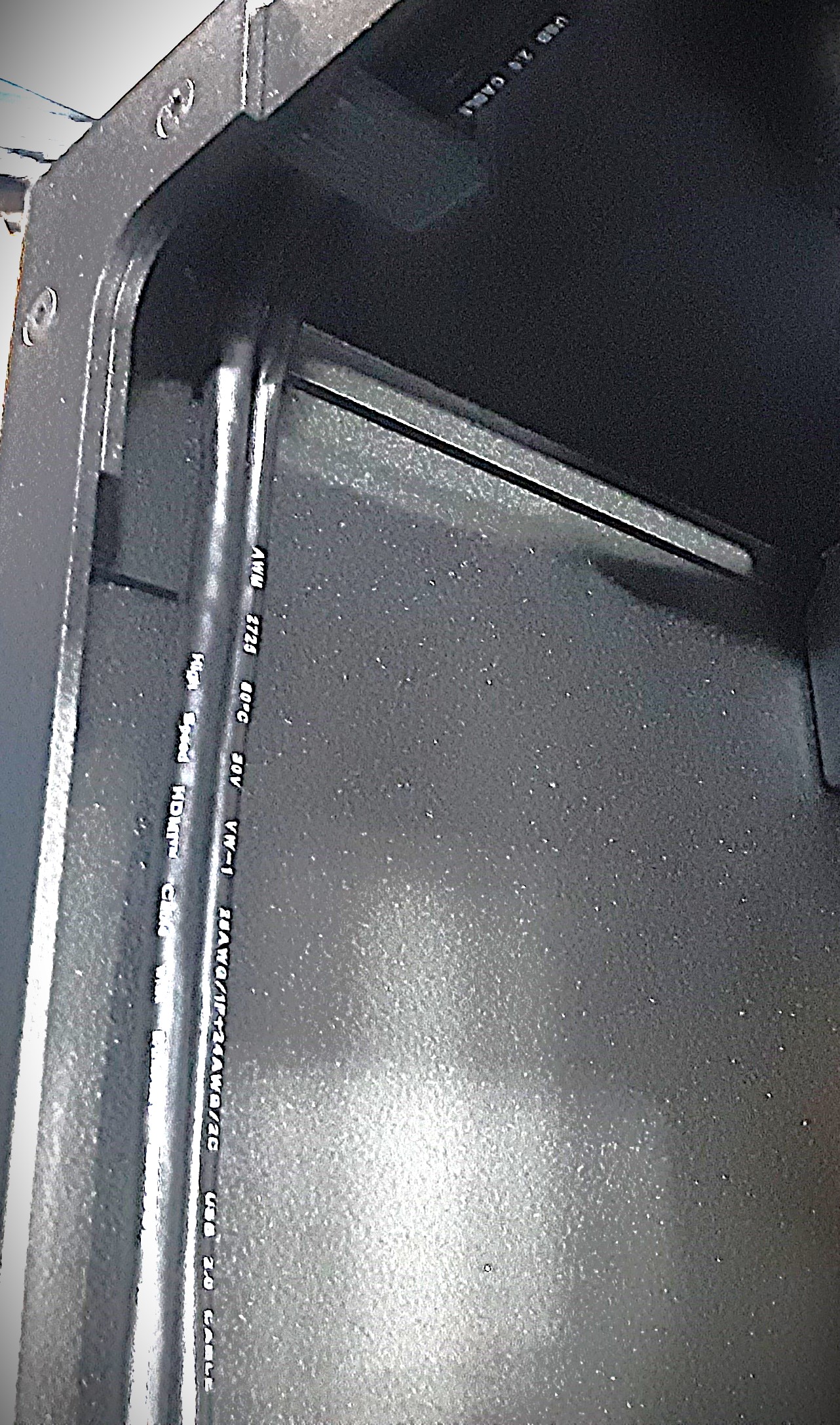
6D) Plug the USB and Micro HDMI cables into PC-BD0127.
6E) Slide PP-GP0833 over the screen wires with the opening of the “U” shape facing the back of the frame loosely attach to the F.A. using HD-BT0157 x2 and HD-WA0038 x2.
6F) Slide PP-GP0833 x2 over the screen wires with the opening of the “U” shape facing the back of the frame loosely attach to the F.A. using HD-BT0128 x4.
6G) Route the screen wires into the PP-GP0833 on the back of the S.A. and plug the wires into the screen.
6H) Make sure the wires are tucked in the corner and tighten HD-BT0157 x2 and HD-BT0128 x4 to secure PP-GP0833 x3.
6I) Reinstall PP-GP0587 knob.
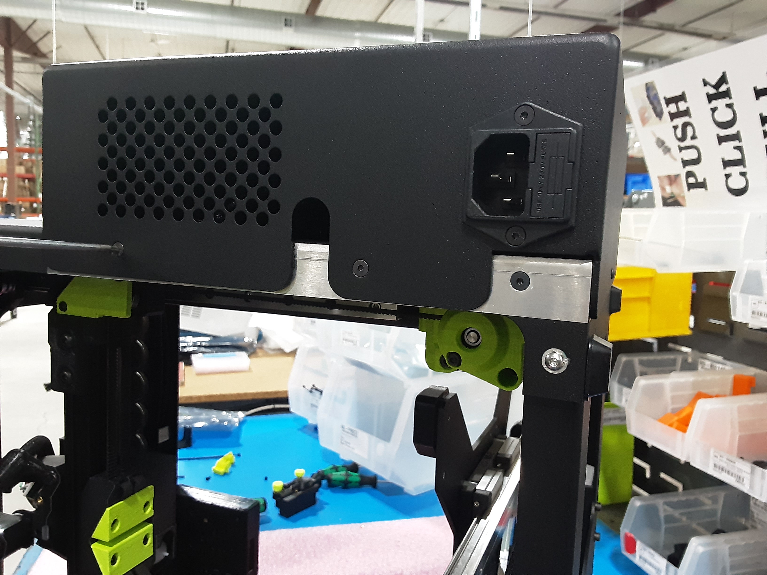
Attach P.B.
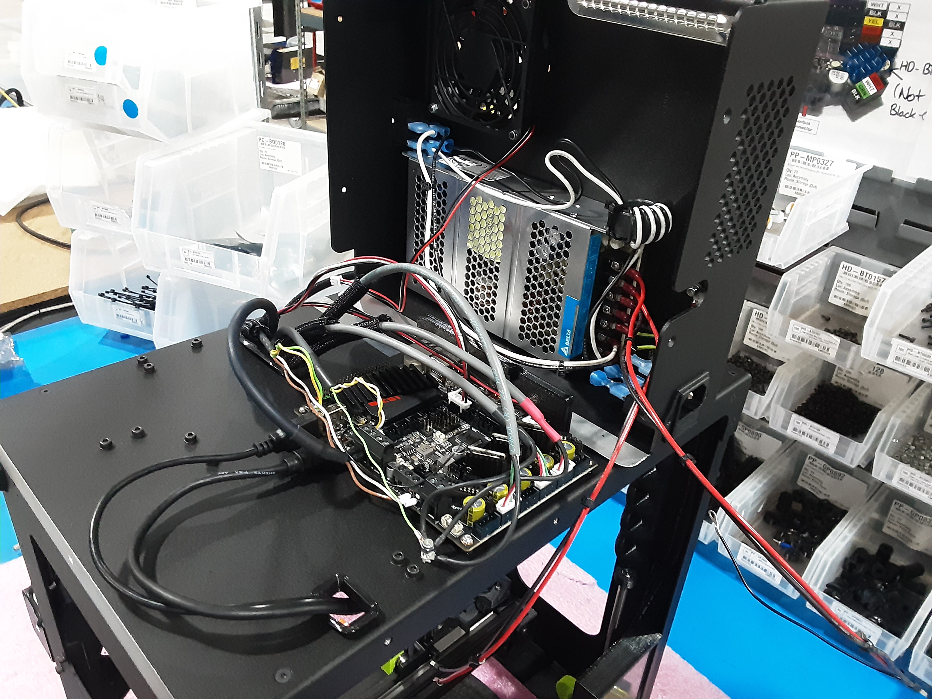
7A) Set the P.B. on the side of the F.A.
7B) Loosen the shown clamp screws on PC-BD0127. With the longer flat side of the terminals on
EL-HR0217 from the P.B. facing the screw head insert the terminals into the correct clamps. Tighten the screws to secure the wires.
7C) Loosen the shown clamp screws on PC-BD0127. With the longer flat side of the terminals on
EL-HR0216 from the P.B. facing the screw head insert the terminals into the correct clamps. Tighten the screws to secure the wires.
7D) Plug EL-HR0227 wire from the P.B. into PC-BD0127 where shown.
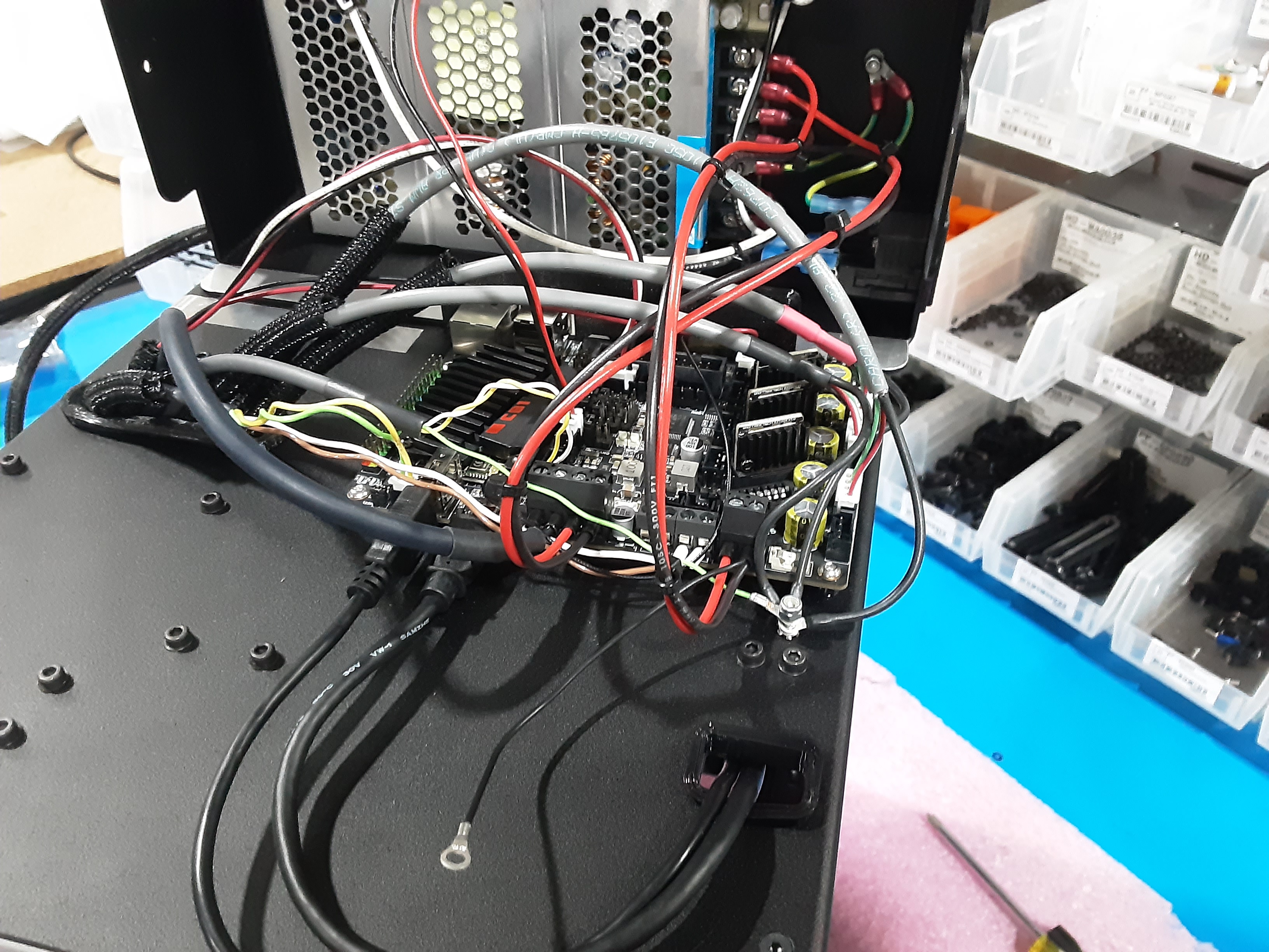
7E) Remove HD-NT0001 from the ground screw and add the ground from EL-HR0216 to the ground screw and secure the five wires using the HD-NT0001.
7F) Lay the P.B. onto the F.A. and attach using HD-BT0140 and HD-BT0128 x4.
Final Steps
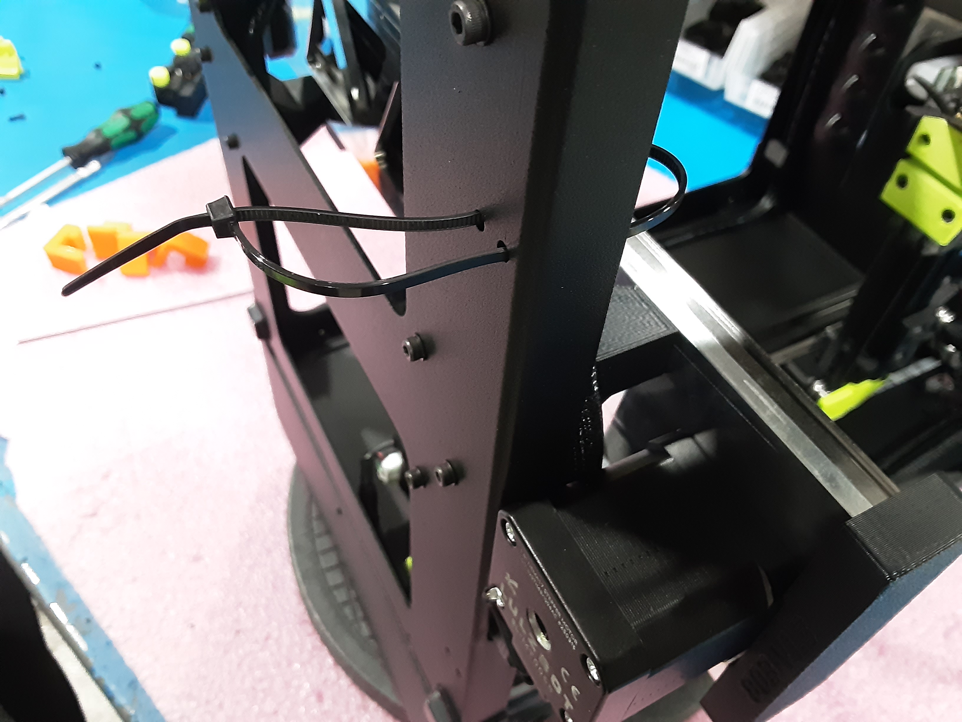
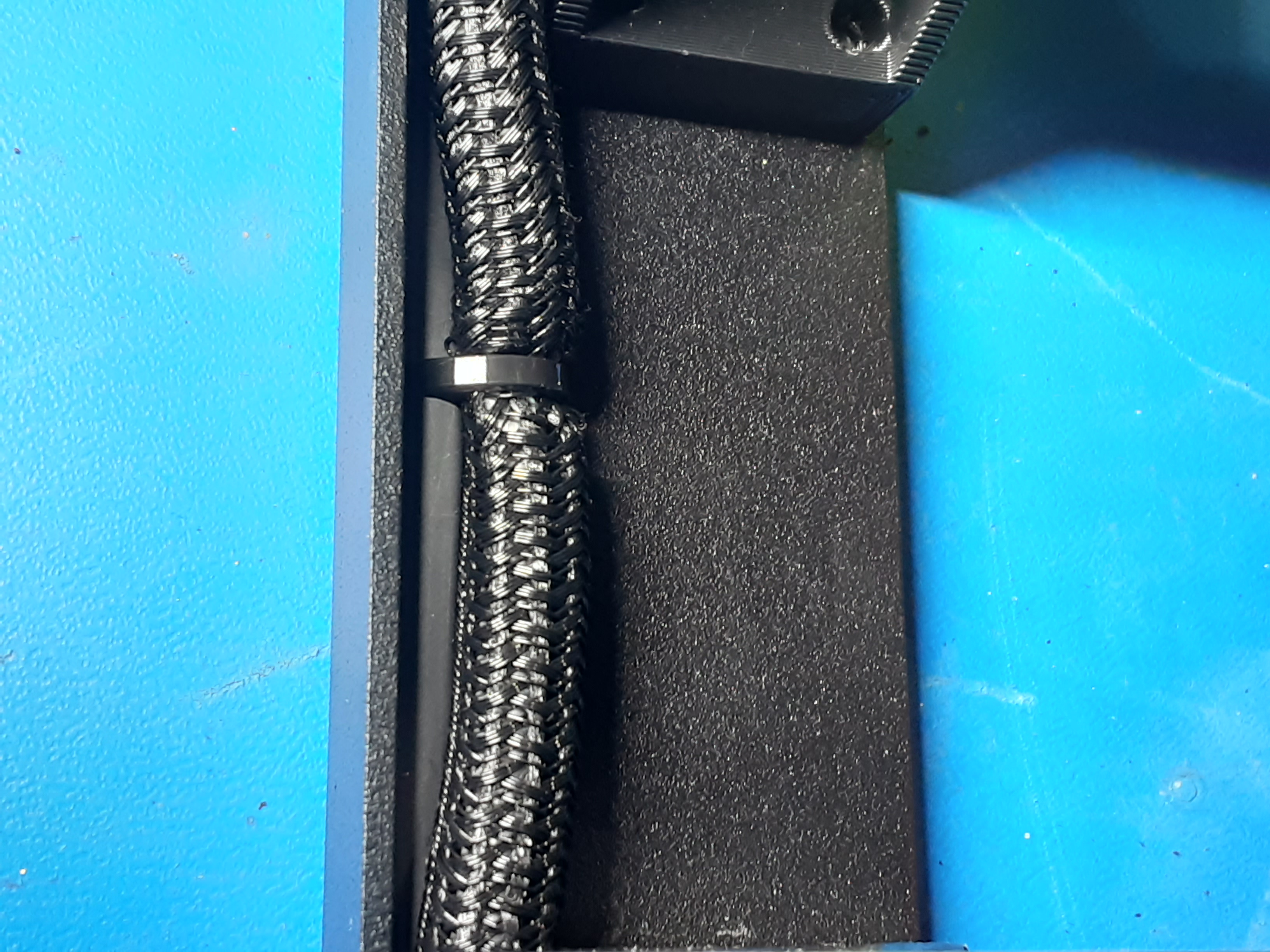
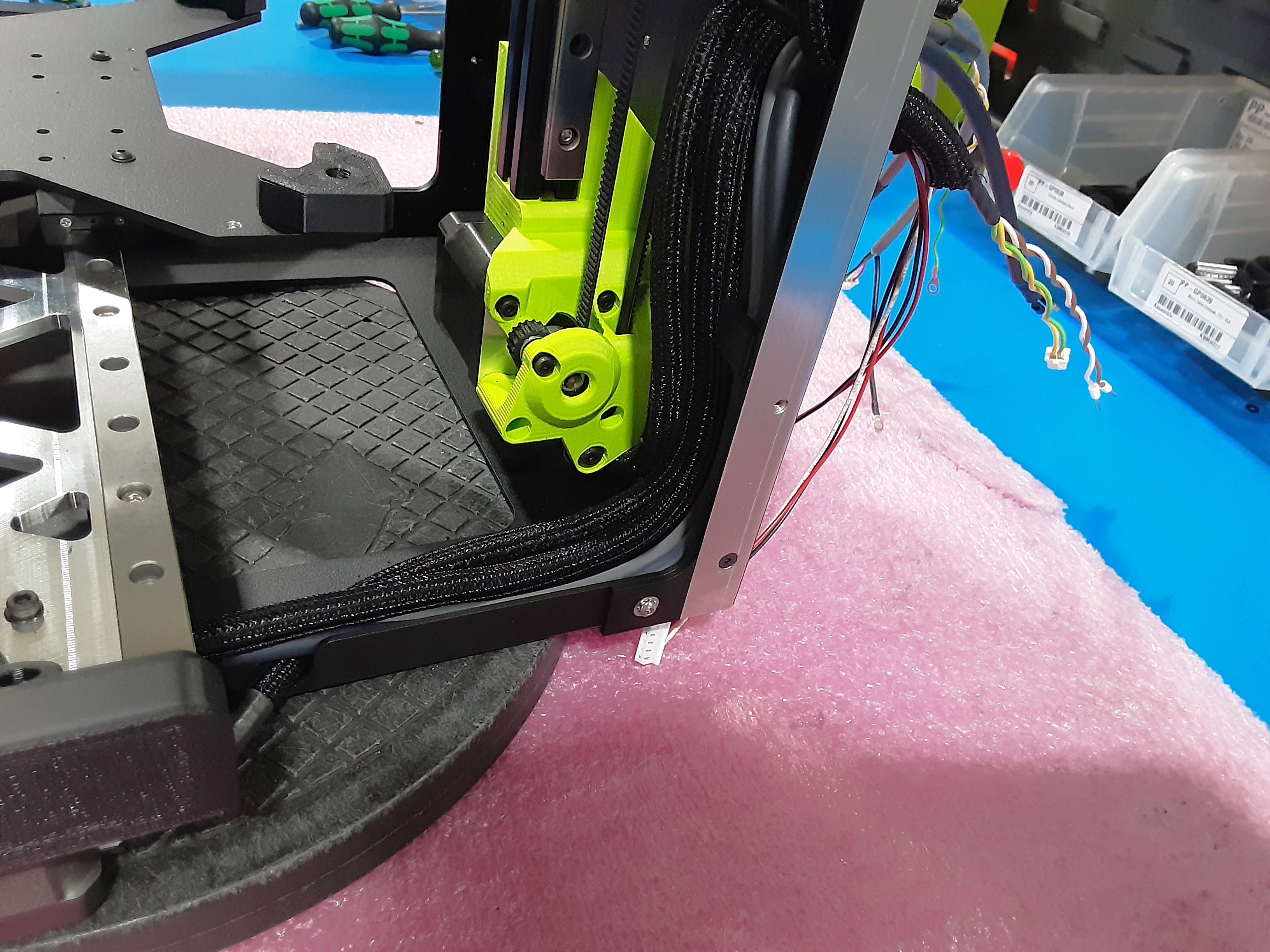
8A) Using HD-MS0058 x2 secure the gray wires from the Y.A.B. and two of the wires from AS-CB0214 to the F.A.
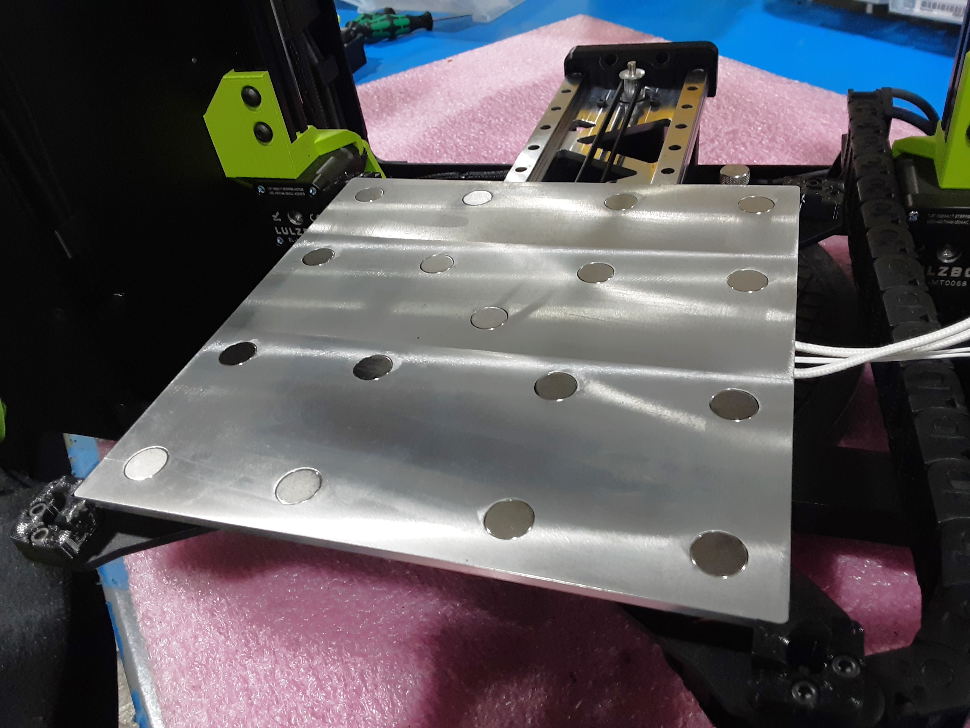
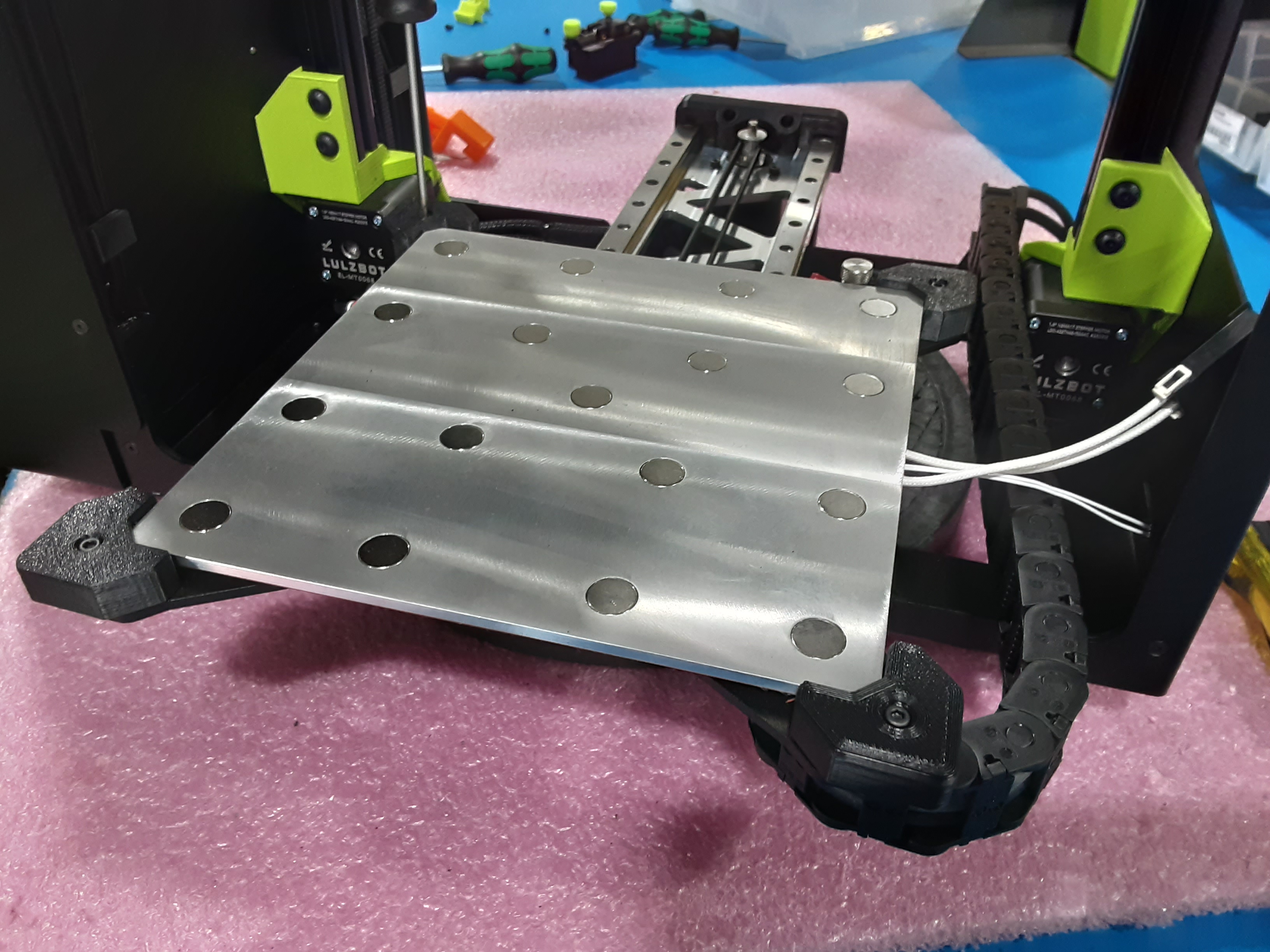
8B) Remove PP-GP0930 x4 from the Y.A.B. and place AS-HB0035 on PP-GP0883 x4 from the Y.A.B. in the shown orientation.
8C) Place PP-GP0930 back on over PP-GP0883 x4 and AS-HB0035 and secure using HD-BT0039 x4.
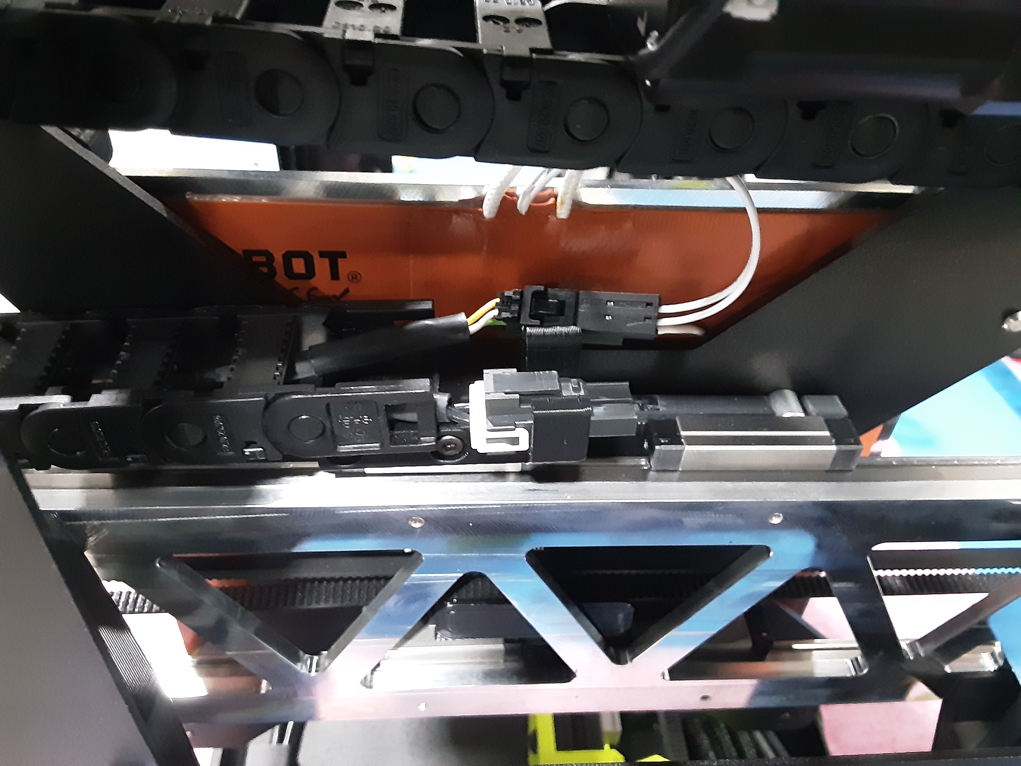
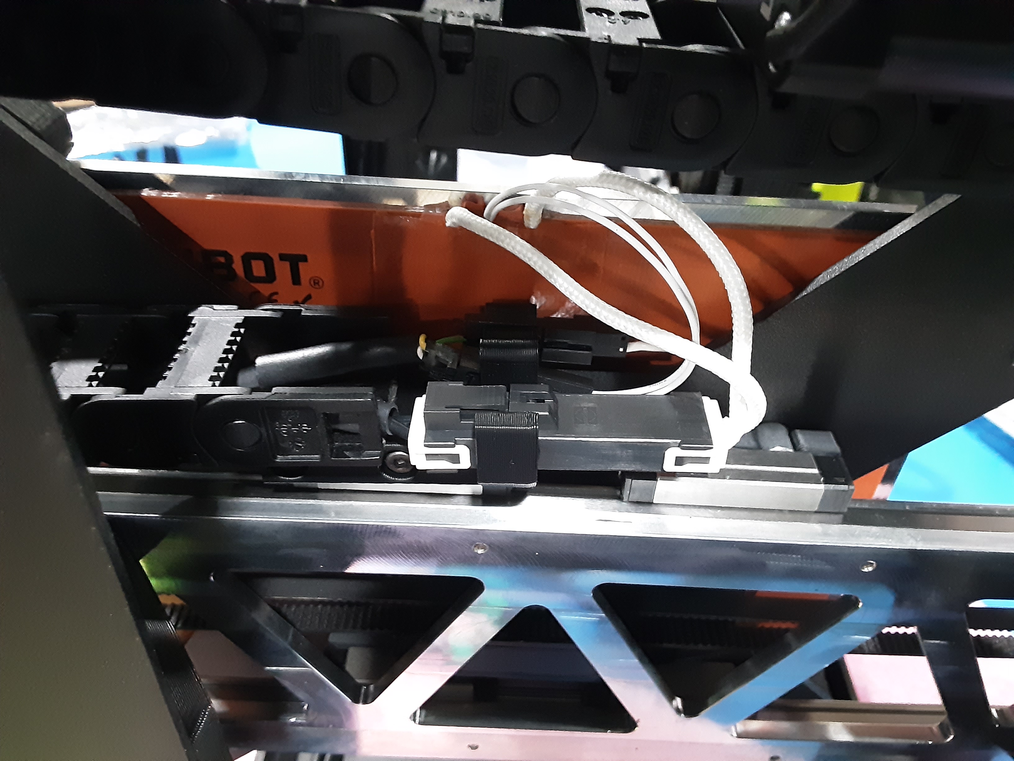
8D) Plug the wires from AS-HB0035 into AS-CB0218 from the Y.A.B.
8E) Make sure the connectors get placed in the channels in PP-GP0805 from the B.A.
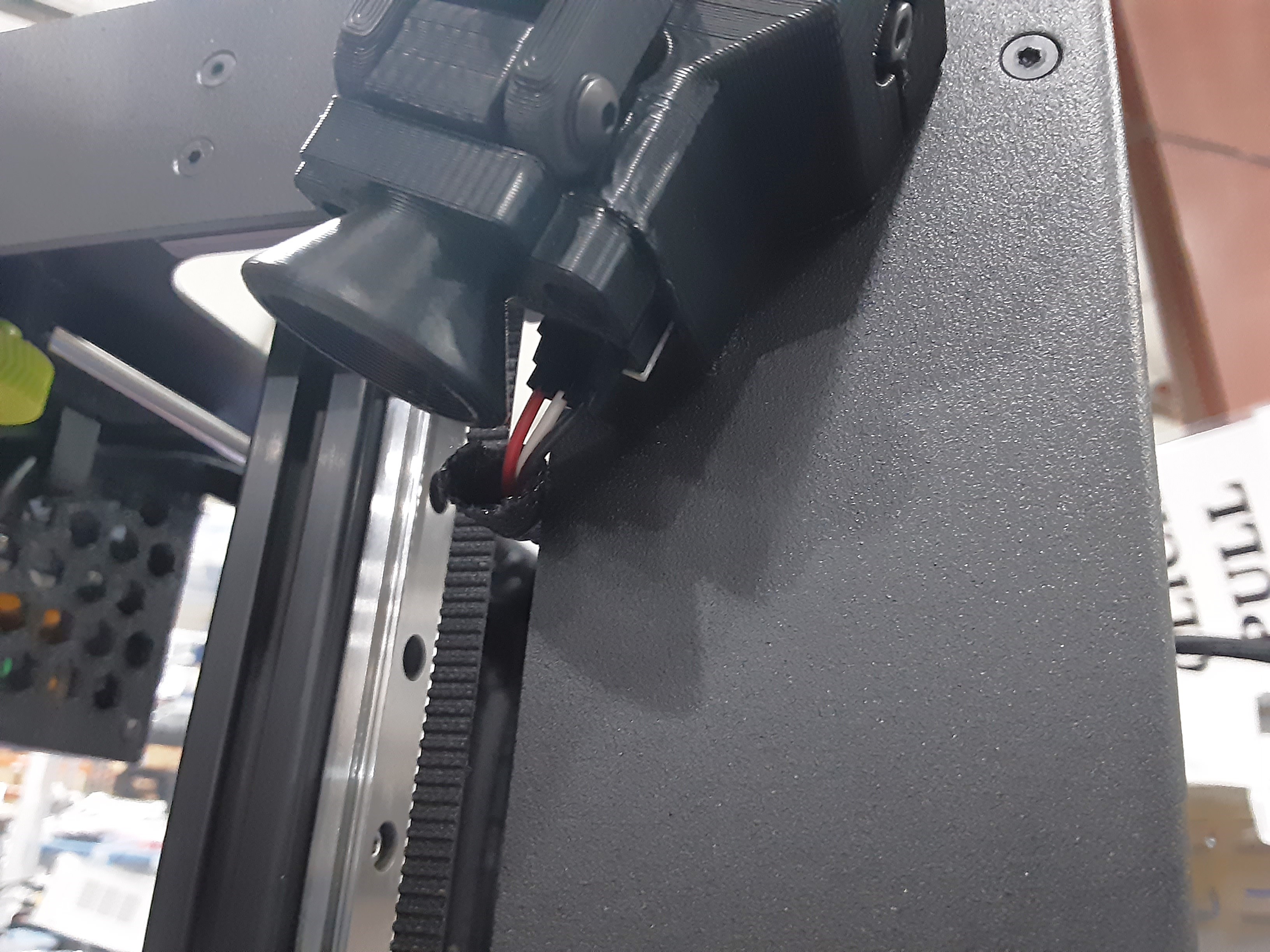
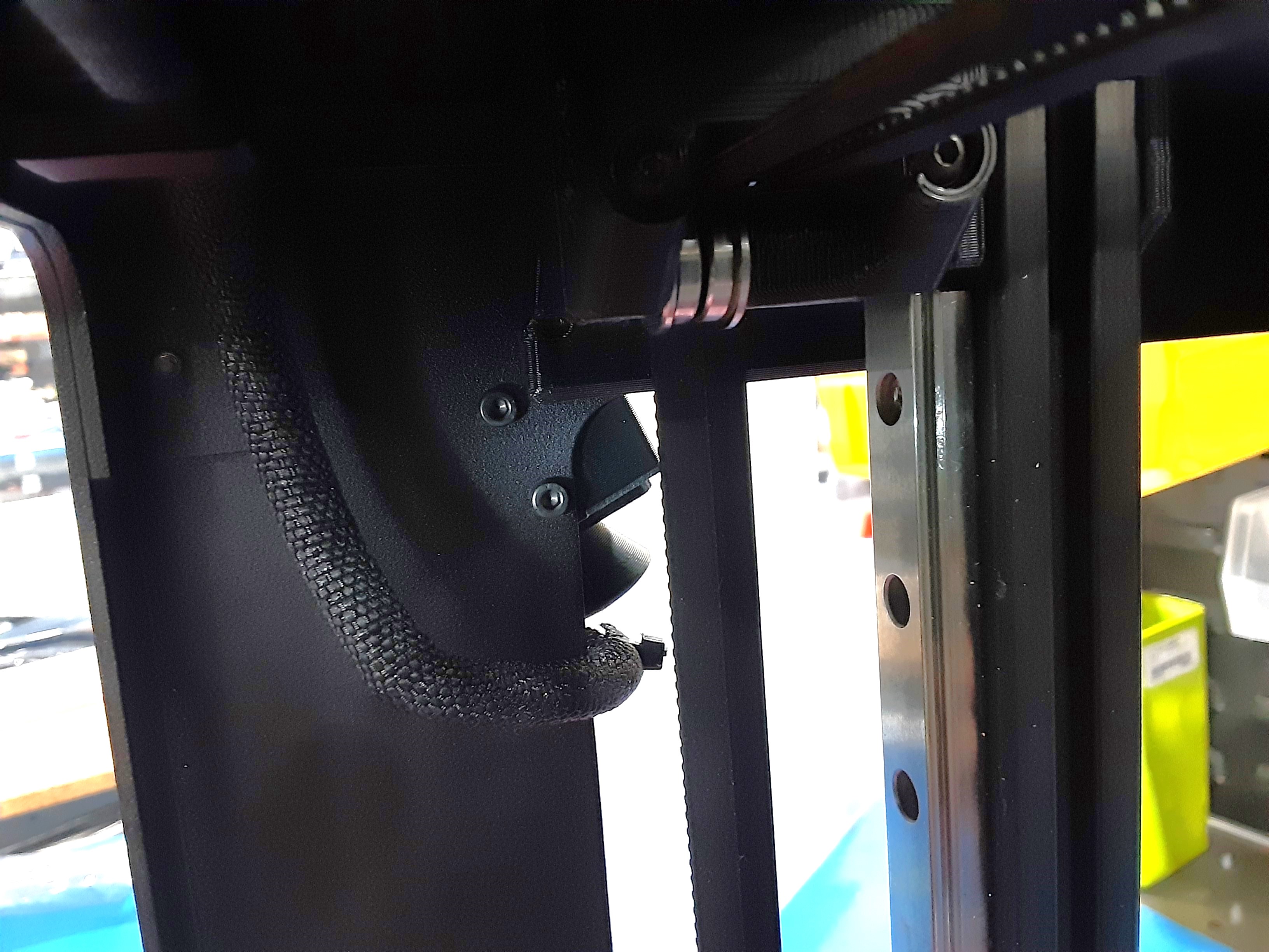
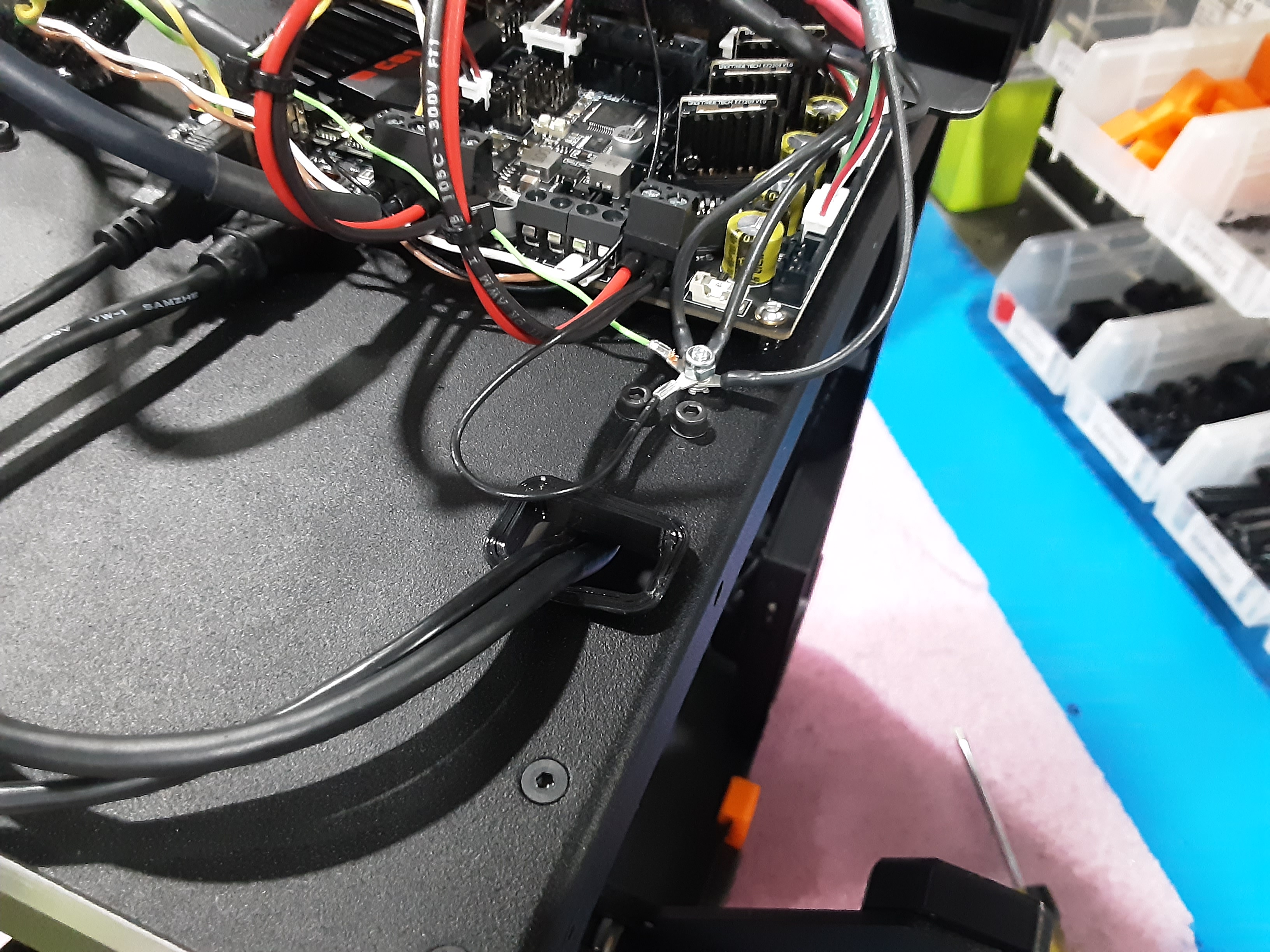
8F) Plug EL-HR0214 from the Z.L.L. into AS-PR0237 and attach to the F.A. using HD-BT0157 x2
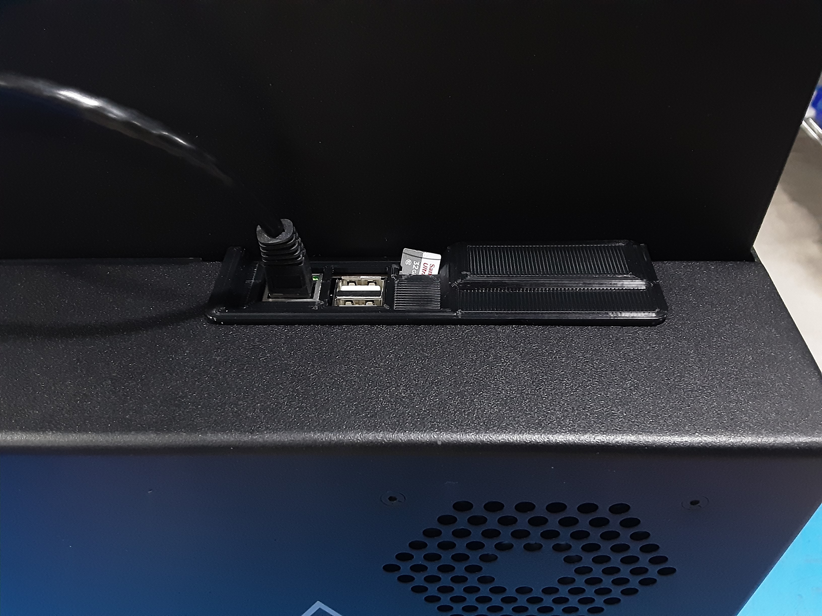
8G) Install EL-MS0011 where shown in proper orientation.
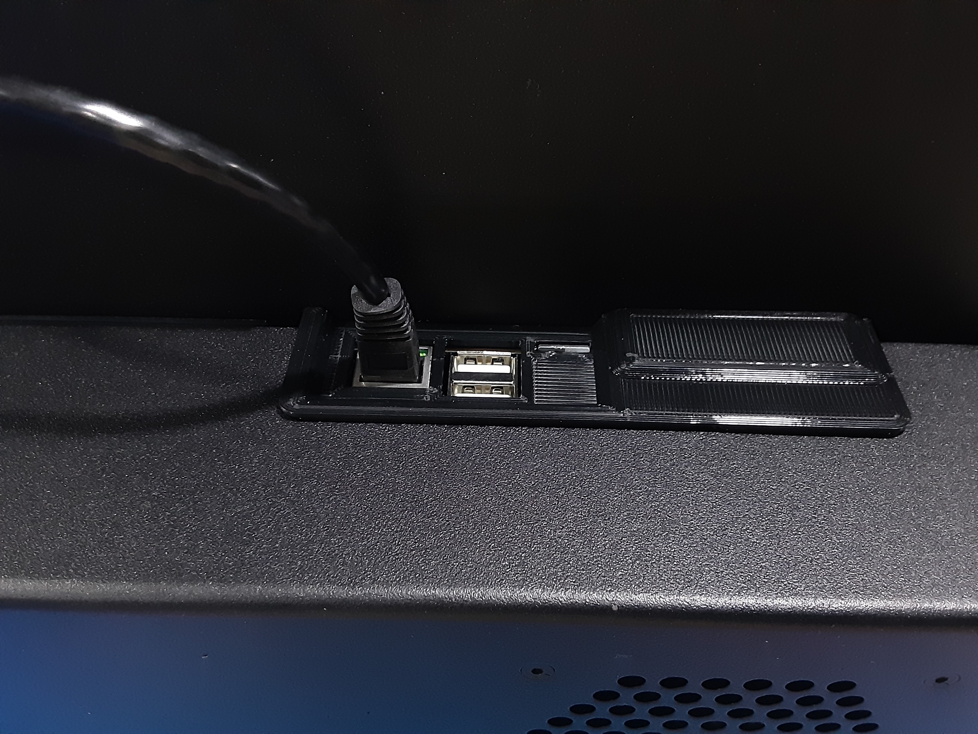
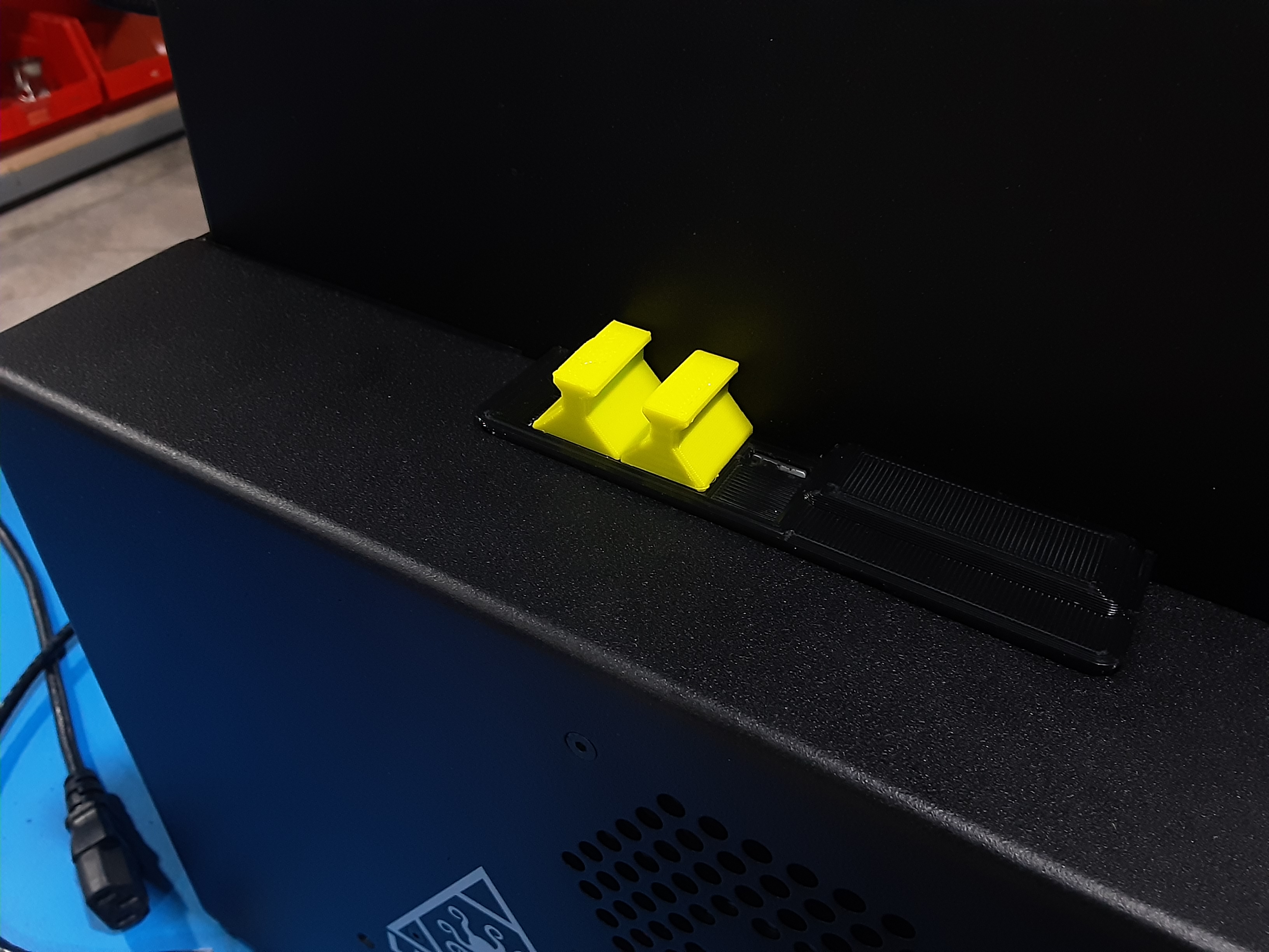
8H) Install PP-GP0990 and PP-GP0991 where shown.