Open HardwareAssembly Instructions
Guides for installation and assembly of the LulzBot line of products made by FAME 3D LLC.
Guides for installation and assembly of the LulzBot line of products made by FAME 3D LLC.
2x [HD-BT0012] M3 Set Screw (Grub Screw) M3 x 6mmL x 0.5 Black
6x [HD-BT0039] Metric Class 12.9 SHCS Alloy Steel, M3 x 12mm Length, 0.50mm Pitch
4x [HD-BT0104] M3 x 8mm BHCS SST
33x [HD-BT0128] M3 x 6mm FHCS Black-Oxide
1x [HD-BT0196] Black-Oxide Alloy Steel SHCS M5 x 25mm Long, 0.8mm Thread
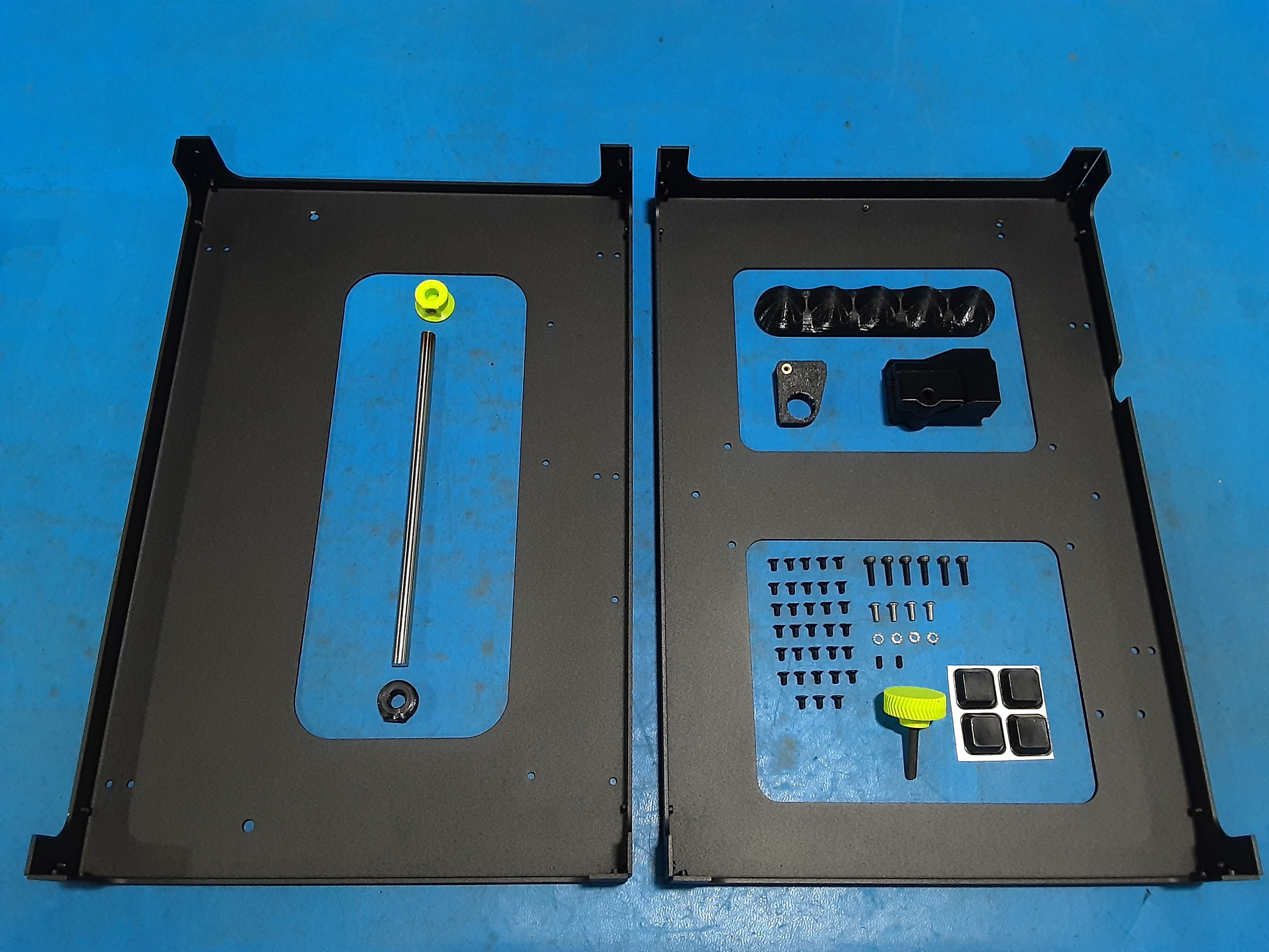
4x [HD-MS0054] Bumper Square, rubber
1x [HD-RD0096] 8mm Smooth rod, 190mm, 300 Series Stainless Steel
4x [HD-WA0035] Metric 18-8 Stainless Steel External Serrated Lock Washer, M3 Size
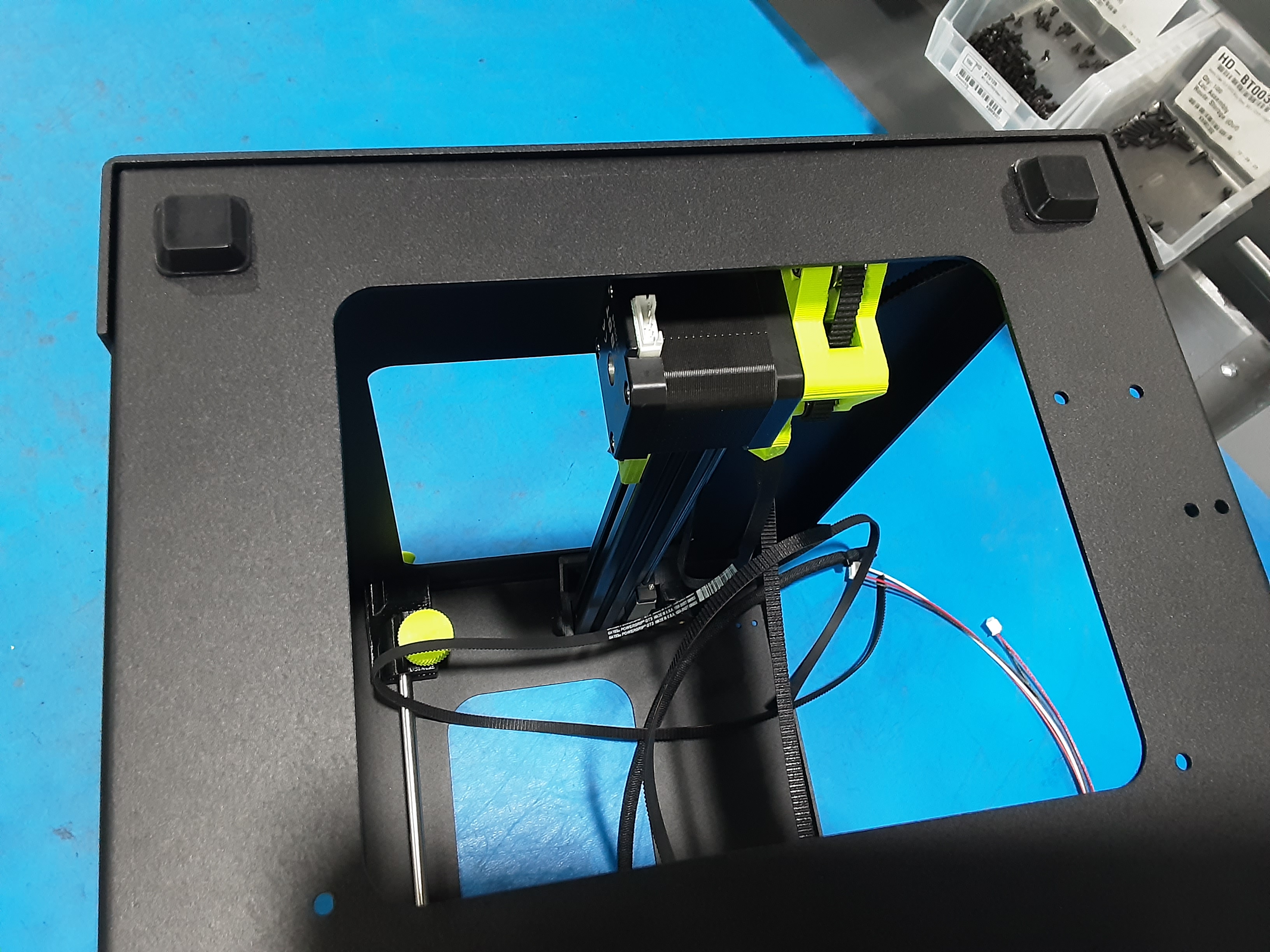
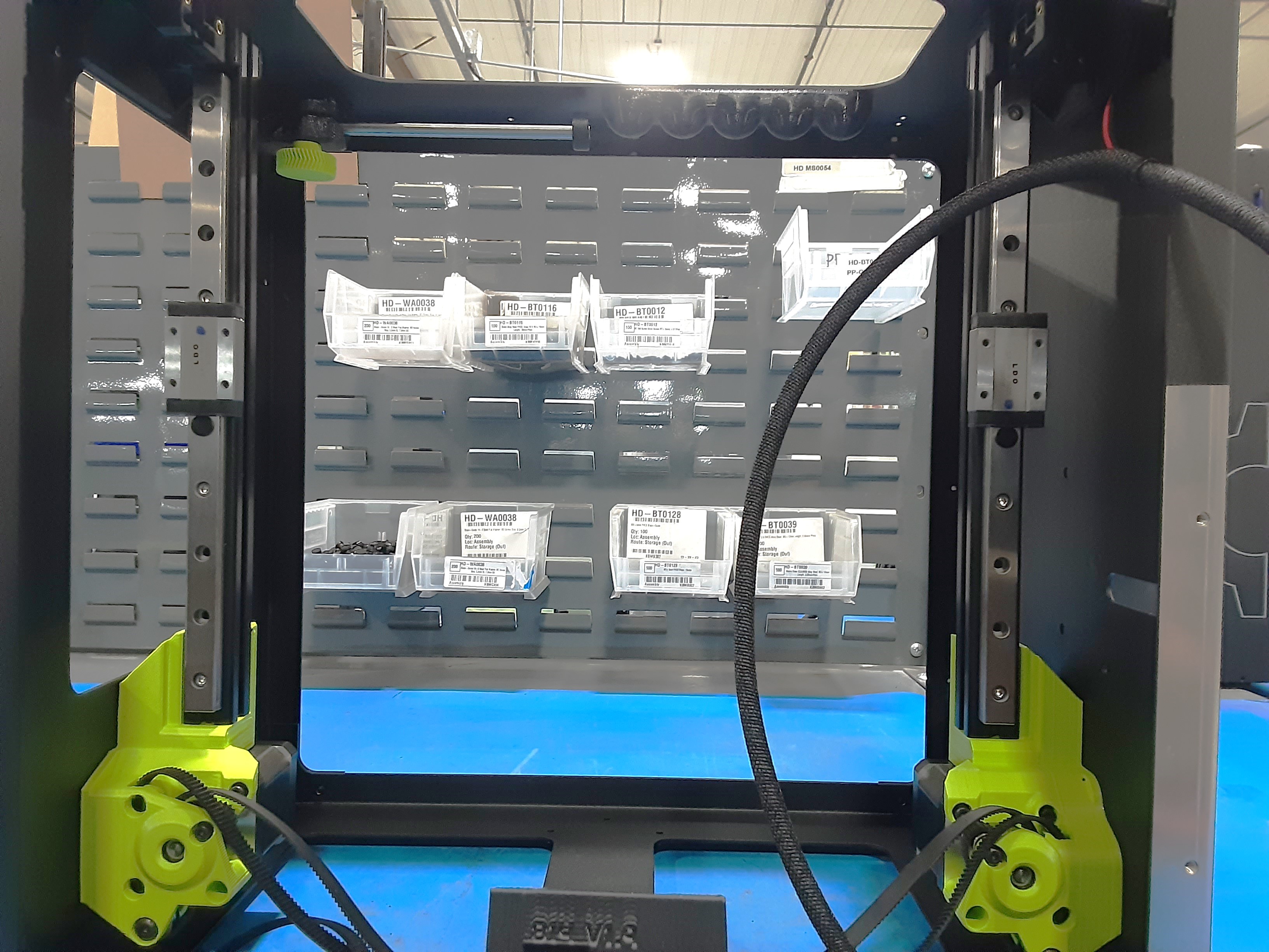
1x [PP-FP0233] Mini3, Top-Plate, 12AWG Aluminum, Rev 0-7
1x [PP-FP0234] Mini3, Bottom-Plate, 12AWG Aluminum, Rev 0-4
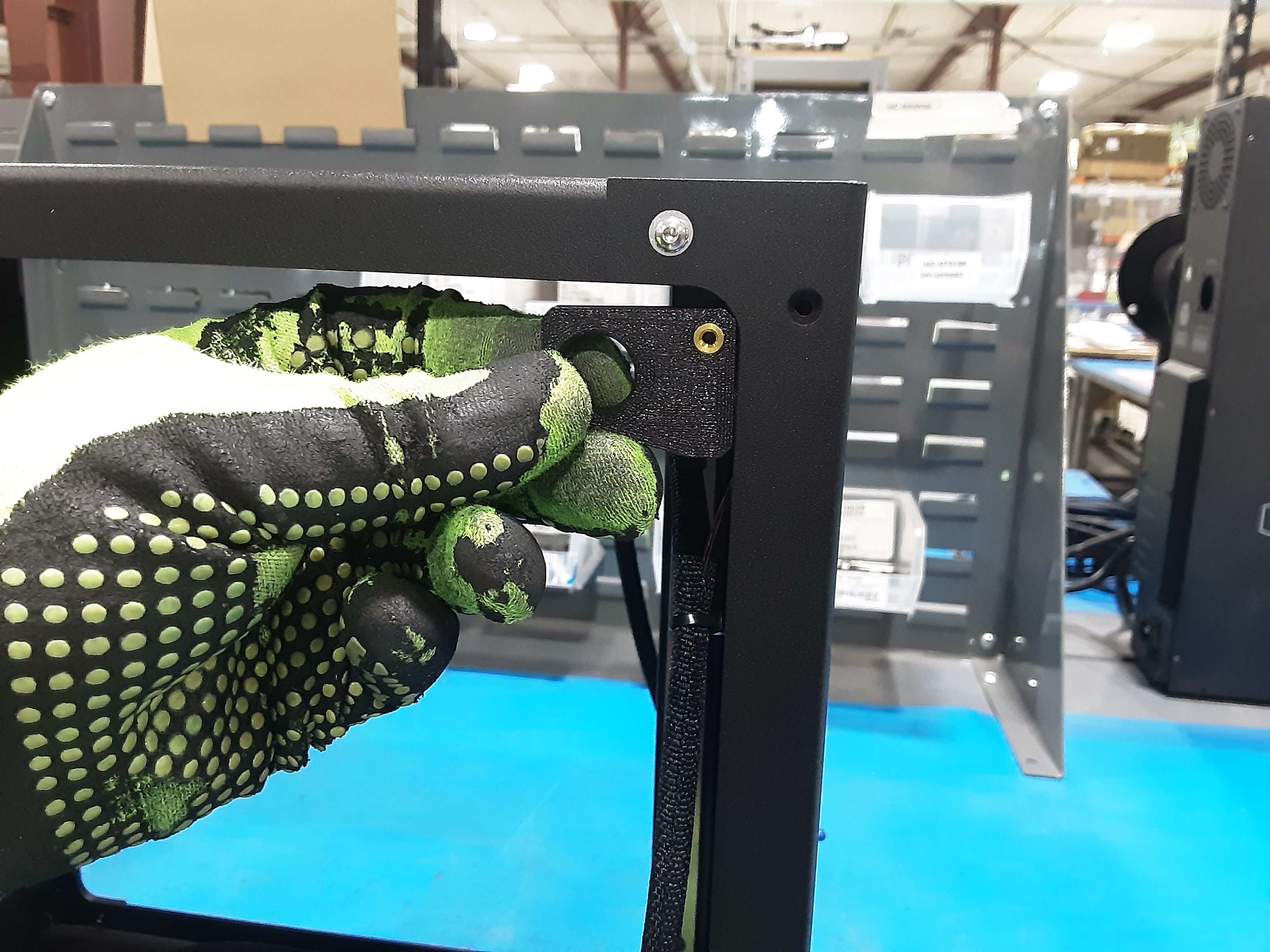
1x [PP-GP0587-GRN] M5 - 28mm DIA Press Fit Knob_TAZ SideKick (LulzBot Green PETg)
1x [PP-GP0817] Mini3, Handle, PETg-BLK
1x [PP-GP0824] Mini3, Spool Mount, ABS-BLK
1x [PP-GP0835] Mini3, Spool Rod End Cap, ABS-GRN
1x [PP-GP0882] Mini3 Spool Shaft End Stop Collar
1x [PP-GP0893] CANBus Support
Z Lower Left Assembly (Z.L.L.)
Z Lower Right Assembly (Z.L.R.)
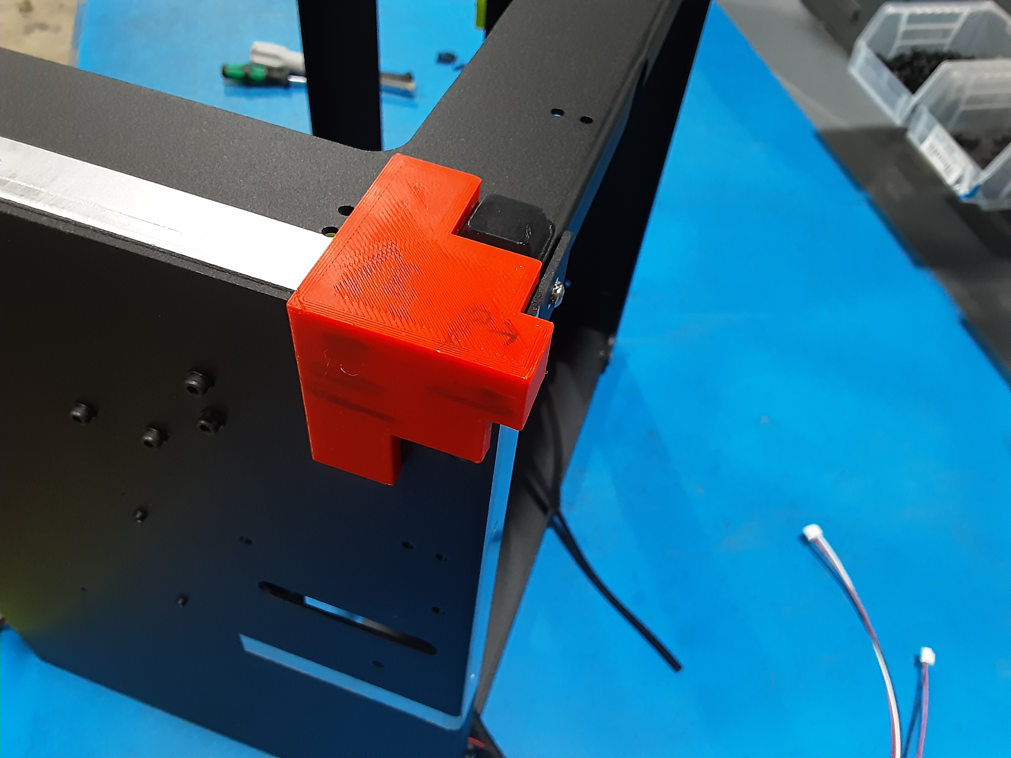
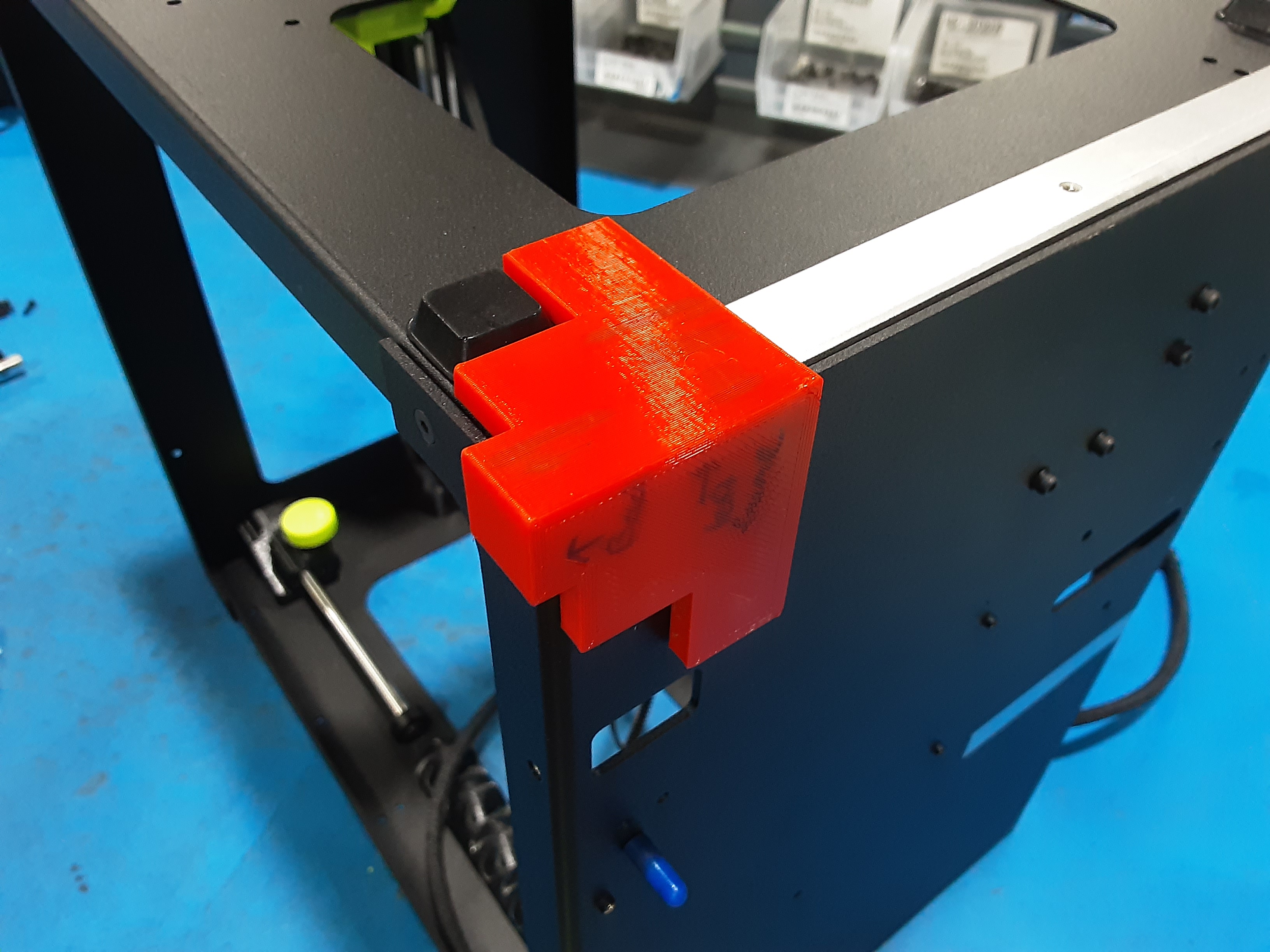
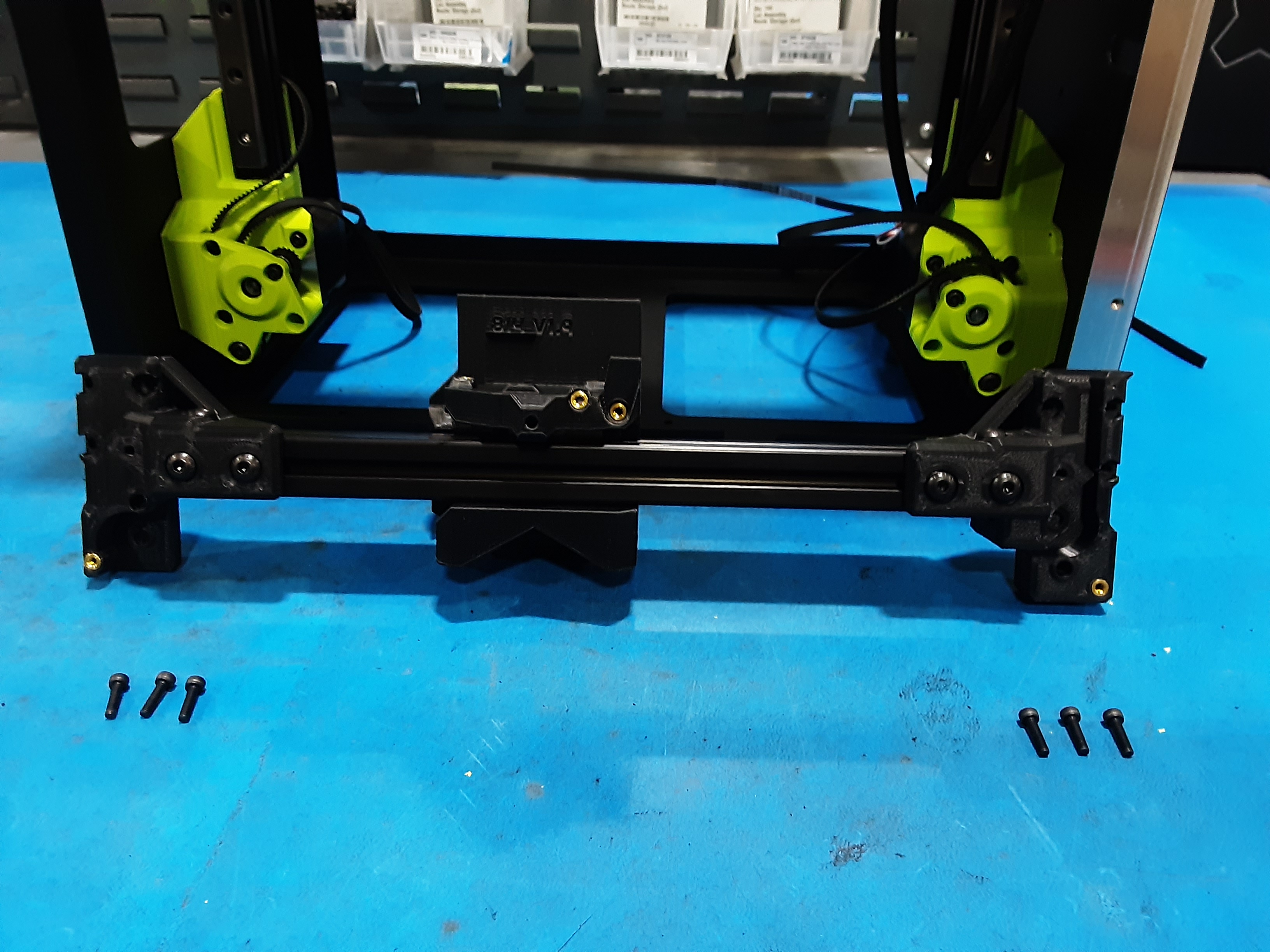
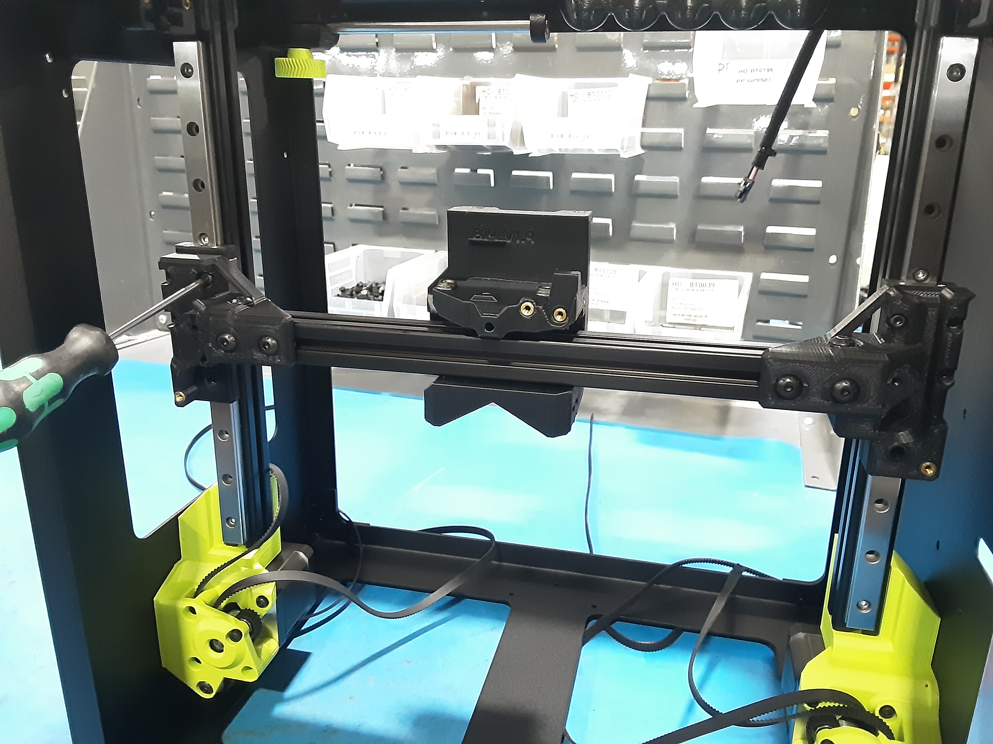
X Carriage Assembly (X.C.A.)
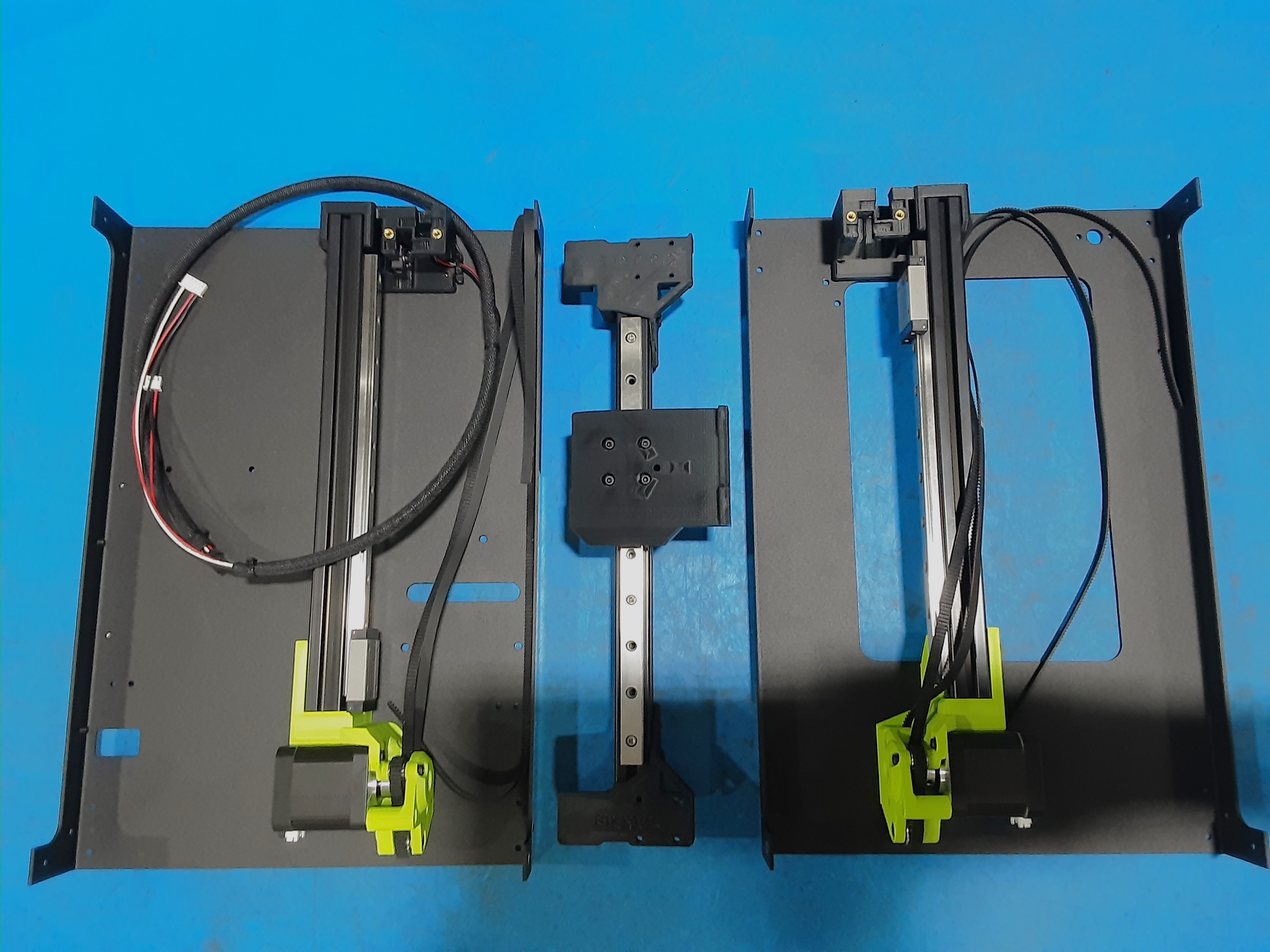
Frame Sides
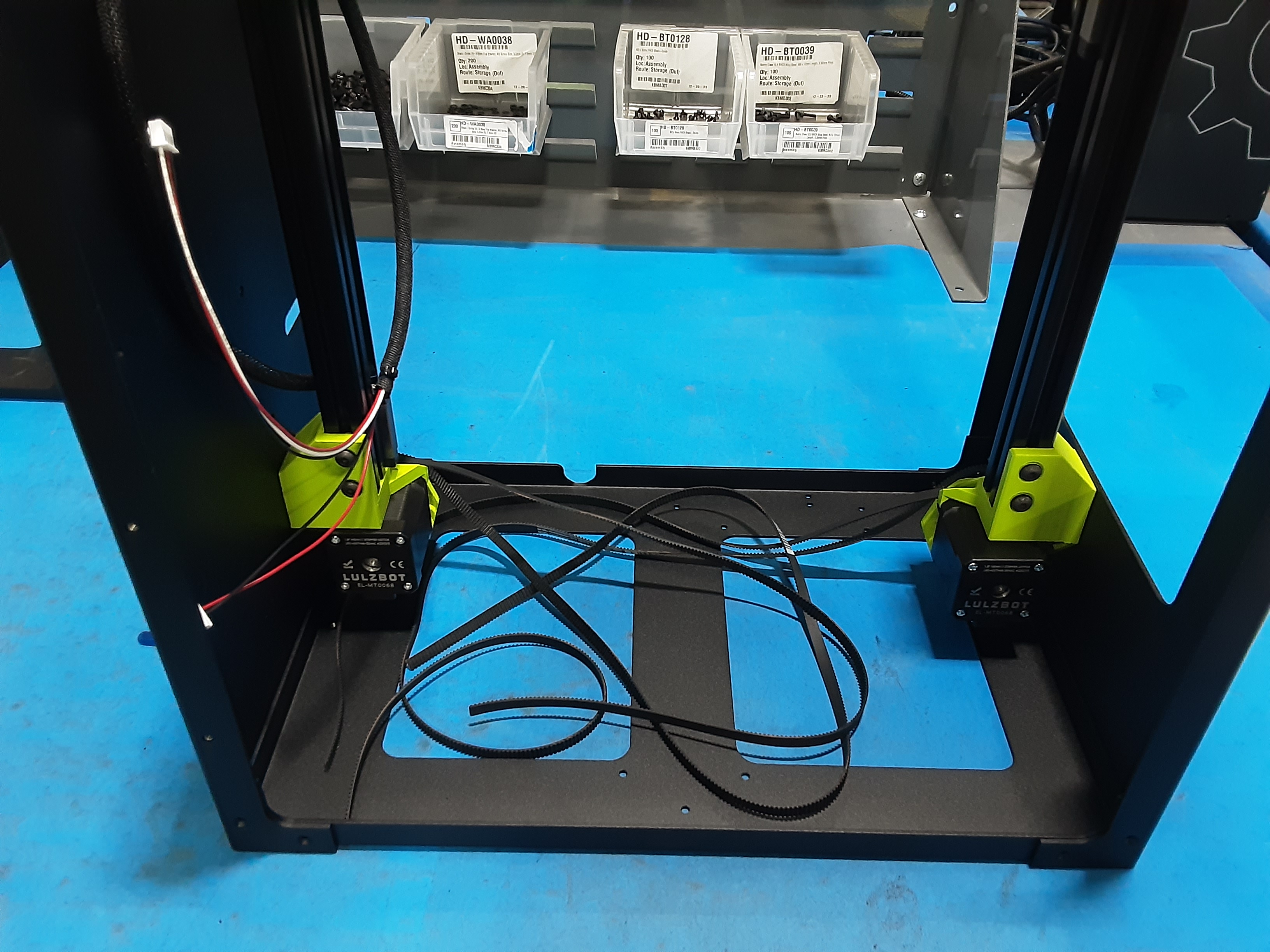
2A) Lay PP-FP0234 down flat with the “U” notch in the back. Slide the Z.L.L. over PP-FP0234 on the left side and Z.L.R. on the right.
2B) Use HD-BT0128 x4 to secure the Z.L.L. to PP-FP0234 on the front.
2C) Use HD-BT0128 x4 to secure the Z.L.R. to PP-FP0234 on the front.
2D) Use HD-BT0128 x3 to secure the Z.L.R. to PP-FP0234 on the back.
2E) Use HD-BT0128 x3 to secure the Z.L.L. to PP-FP0234 on the back.
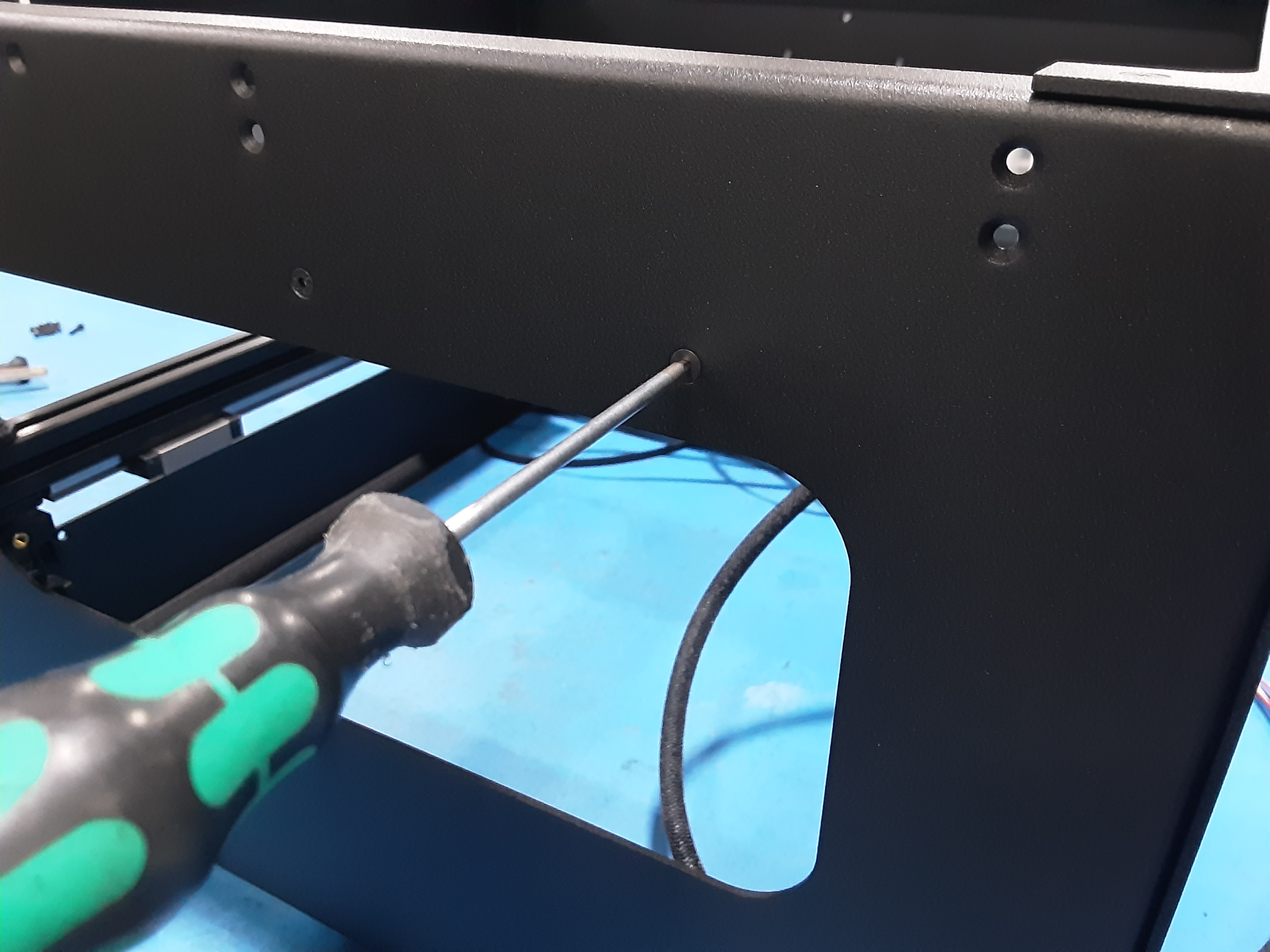
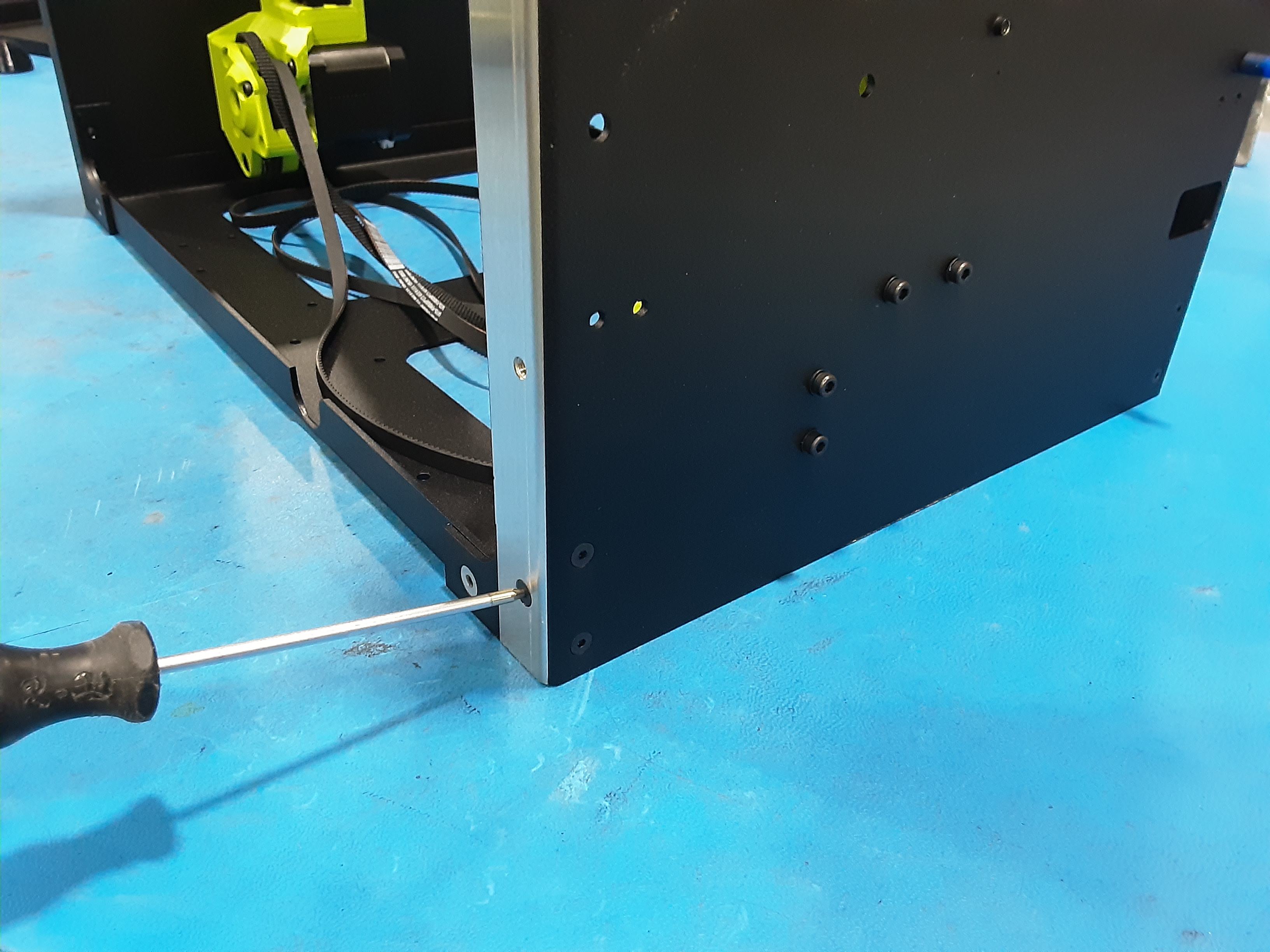
2F) Use HD-BT0104 x2 and HD-WA0035 x2 in the non-coated holes on the back to finish securing the Z.L.L. and Z.L.R. to PP-FP0234.
Frame Top
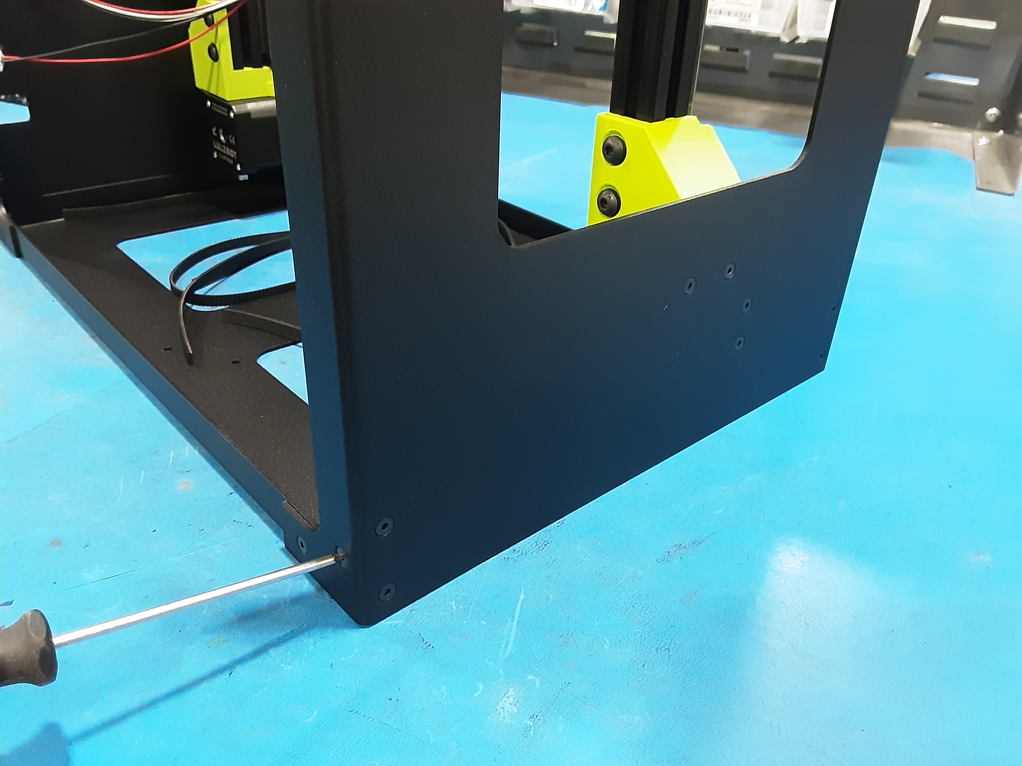
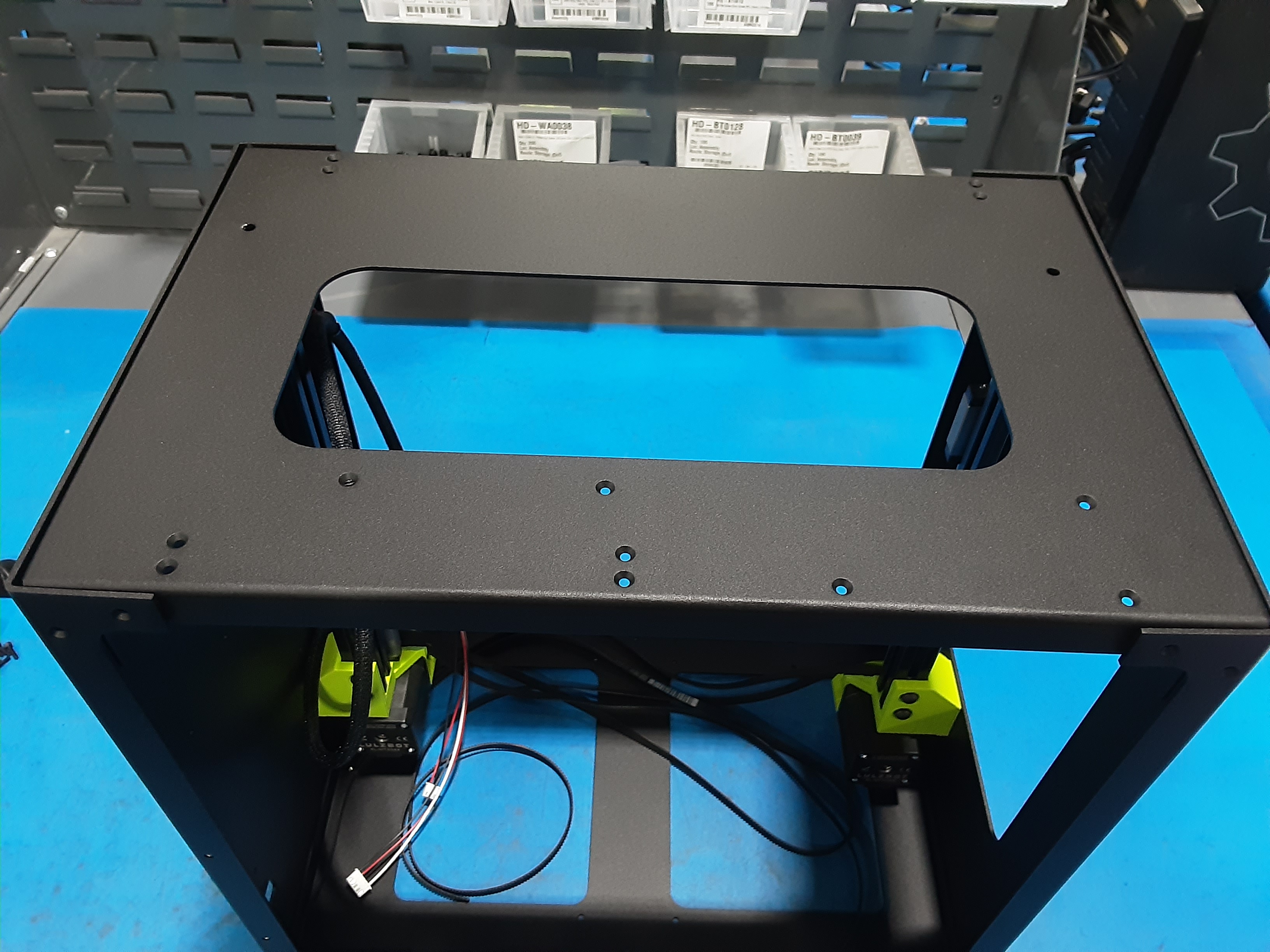
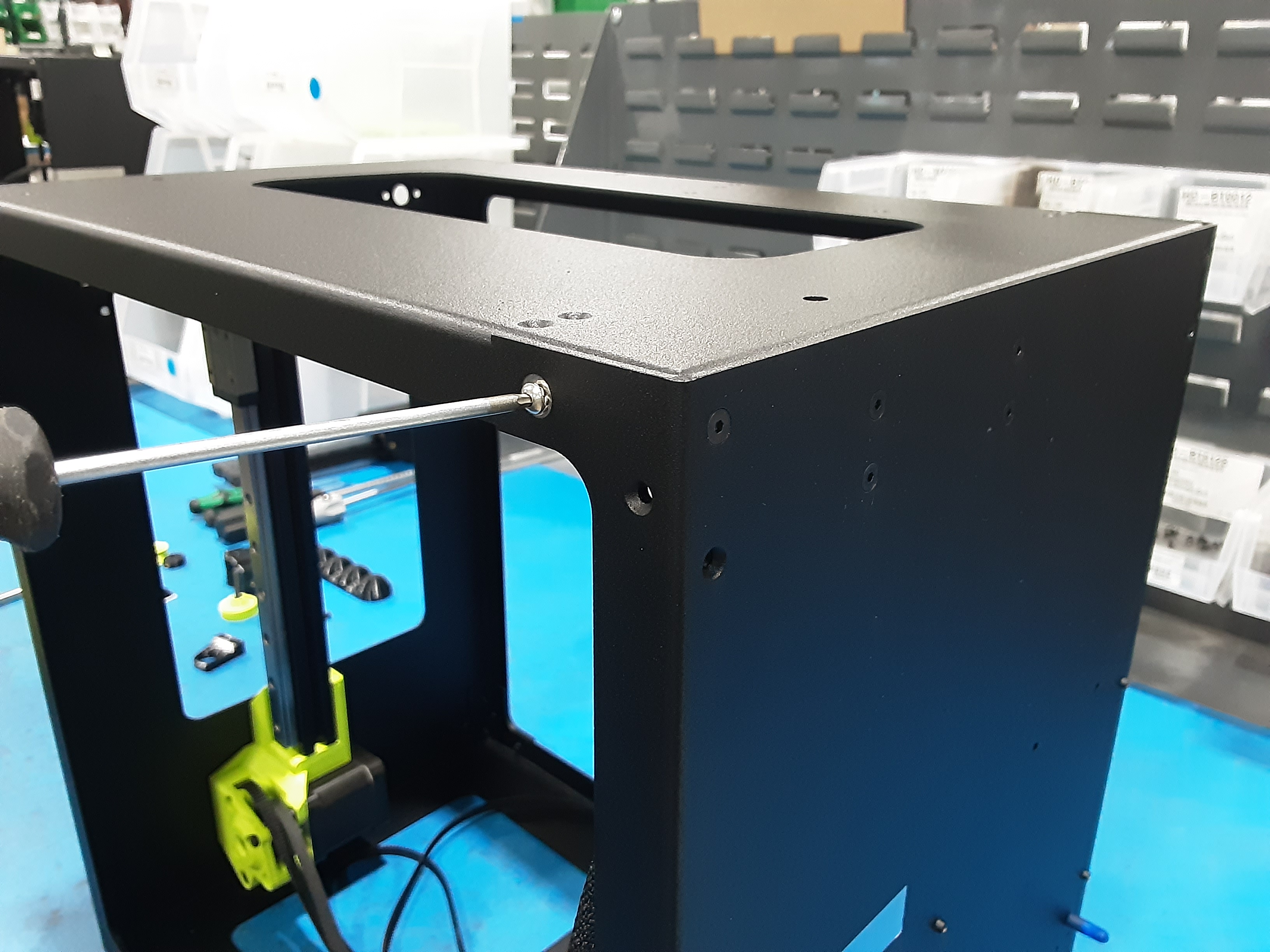
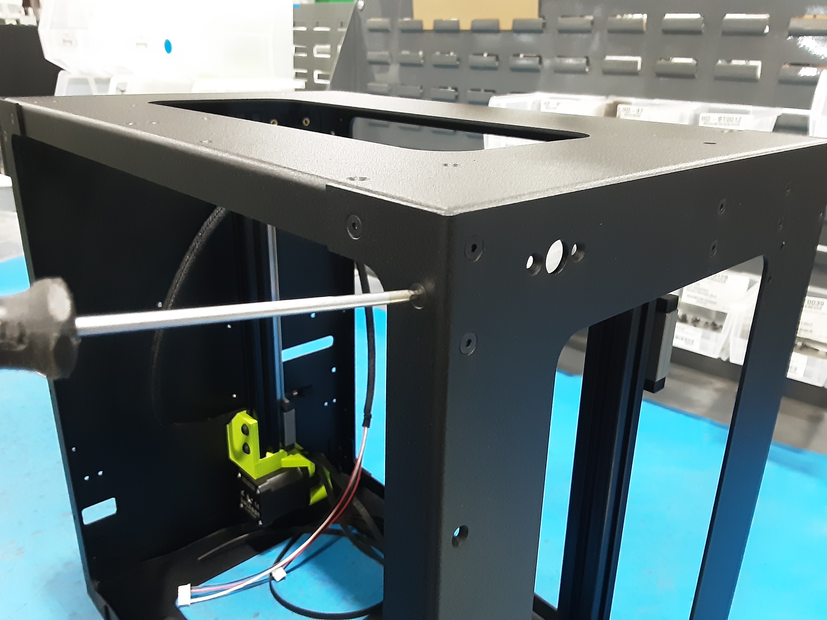
3A) Check orientation then slide PP-FP0233 down on the inside of Z.L.L. and Z.L.R.
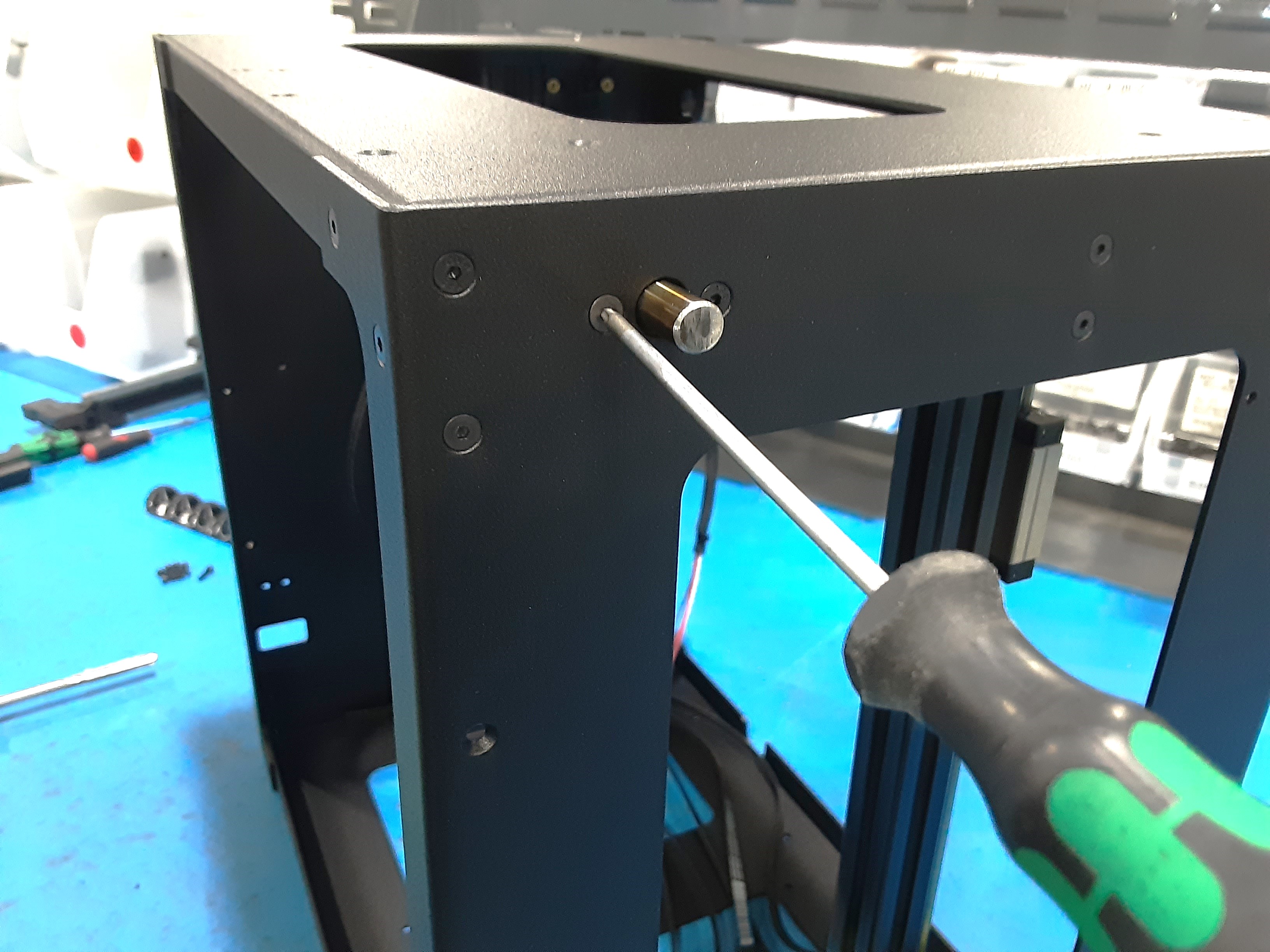
3B) Use HD-BT0104 x1, HD-WA0035 x1, and HD-BT0128 x1 to secure the Z.L.L. to PP-FP0233 on the back.
3C) Use HD-BT0104 x1, HD-WA0035 x1, and HD-BT0128 x3 to secure the Z.L.R. to PP-FP0233 on the back.
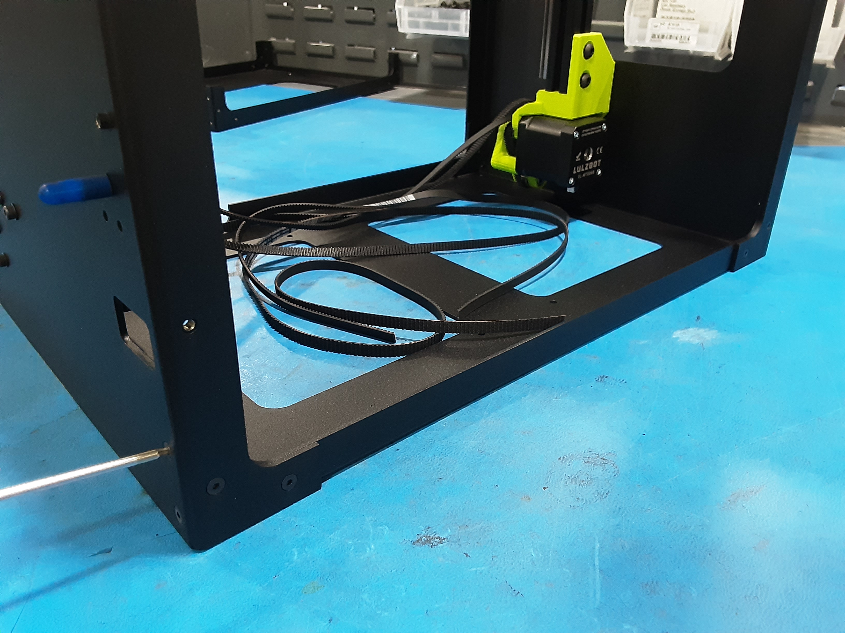
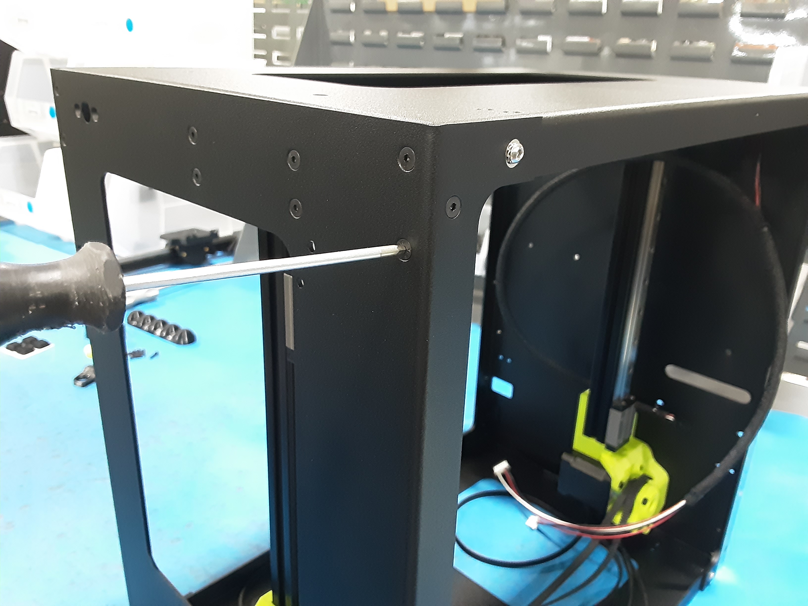
3D) Use HD-BT0128 x4 to secure the Z.L.R. to PP-FP0233 on the front.
3E) Use HD-BT0128 x4 to secure the Z.L.L. to PP-FP0233 on the front.
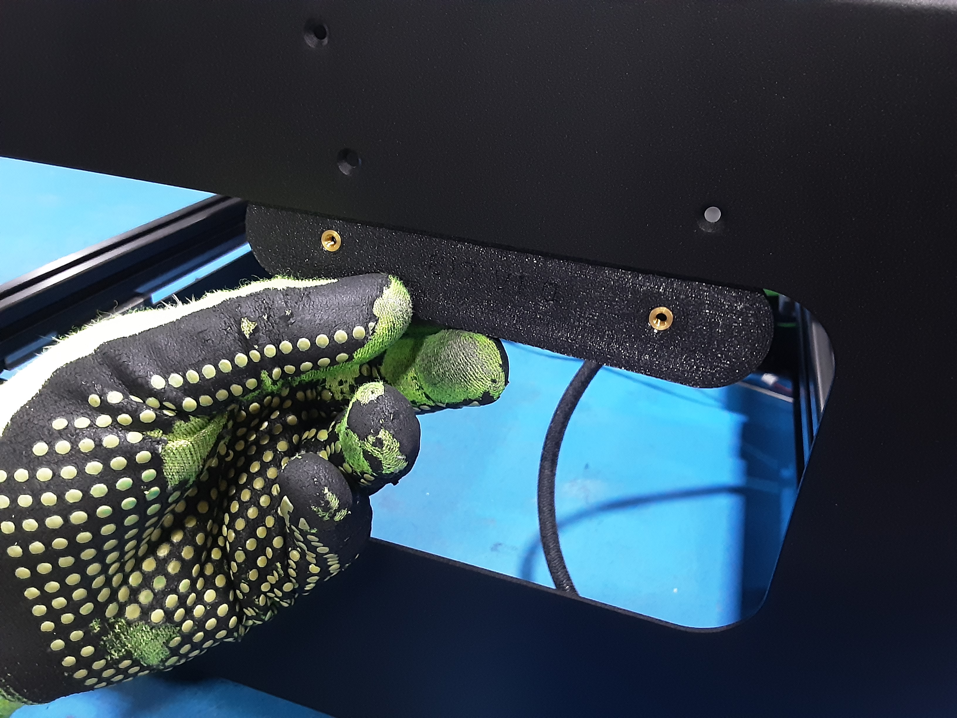
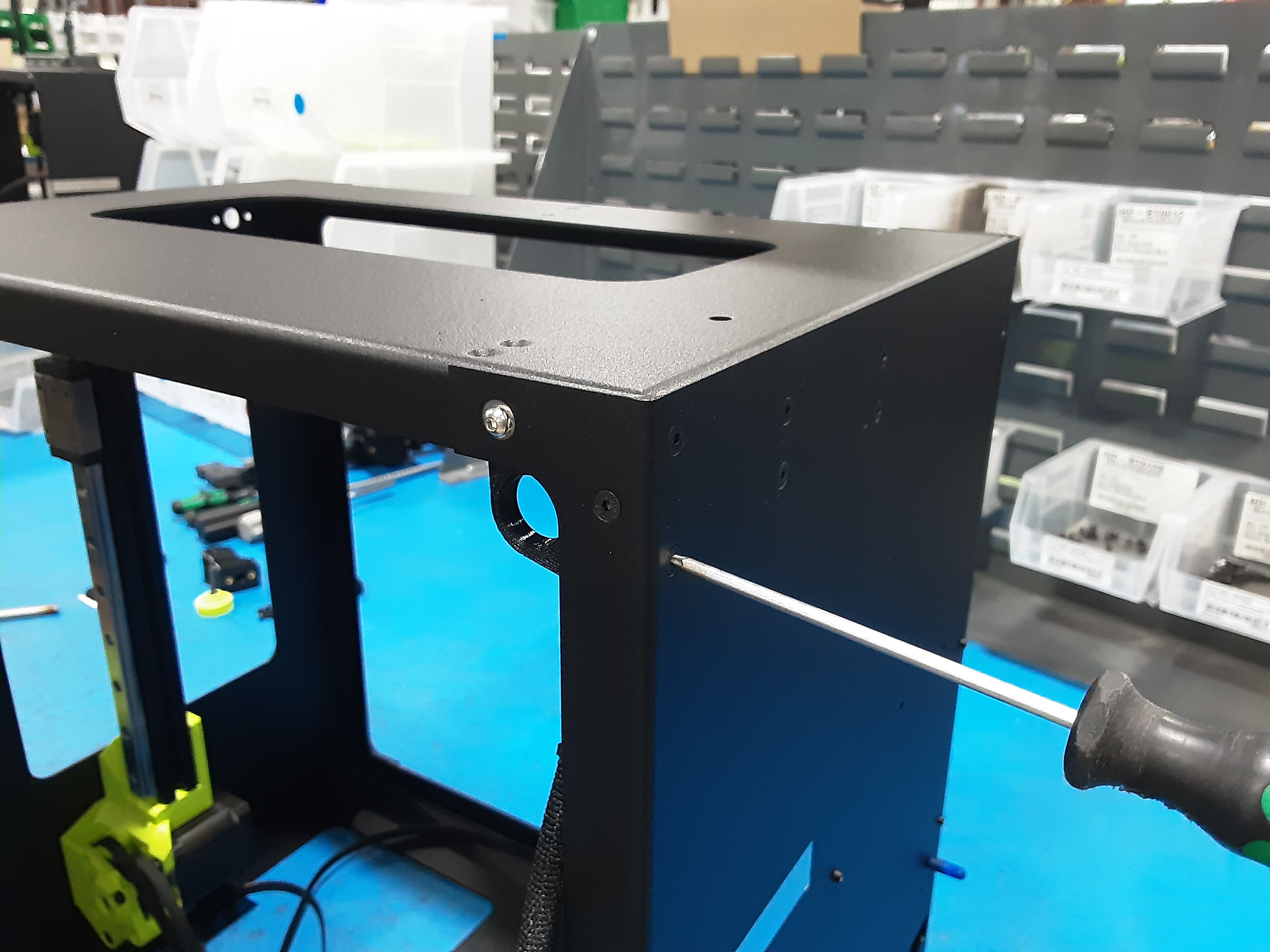
3F) Grab PP-GP0893 x1 and slide it on the inside of Z.L.L. and PP-FP0233 on the back and secure using
HD-BT0128 x2.
Rod Assembly
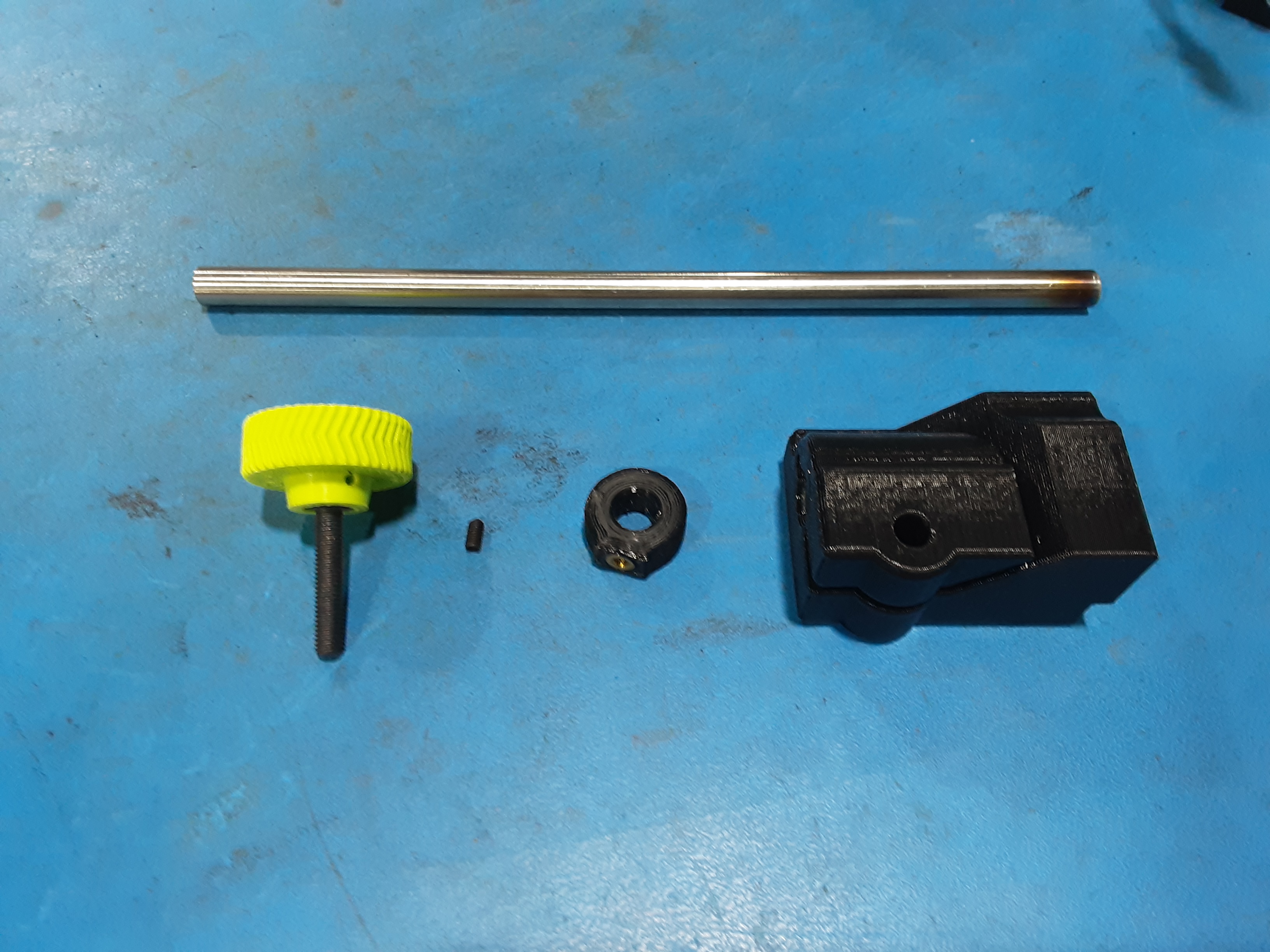
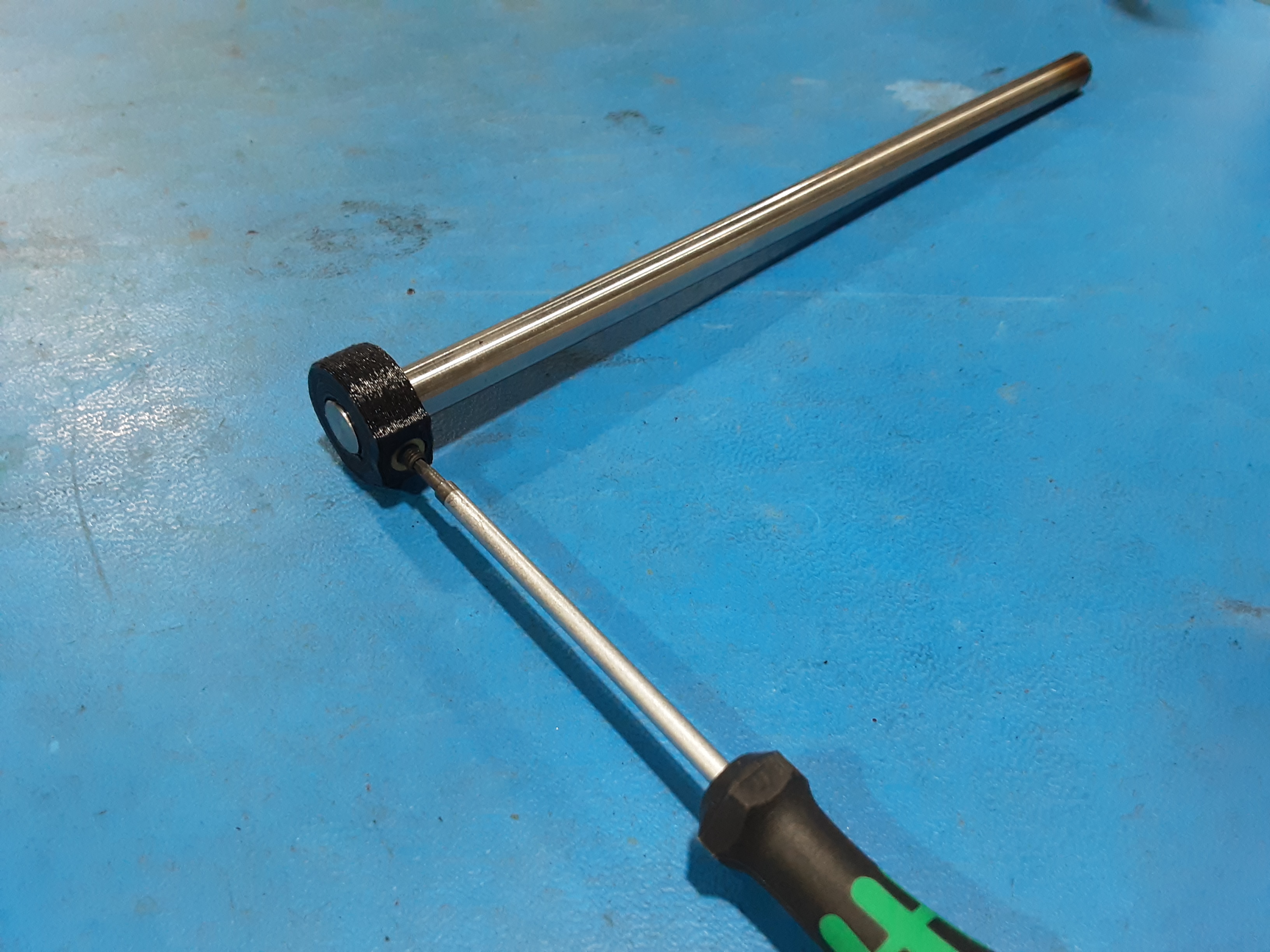
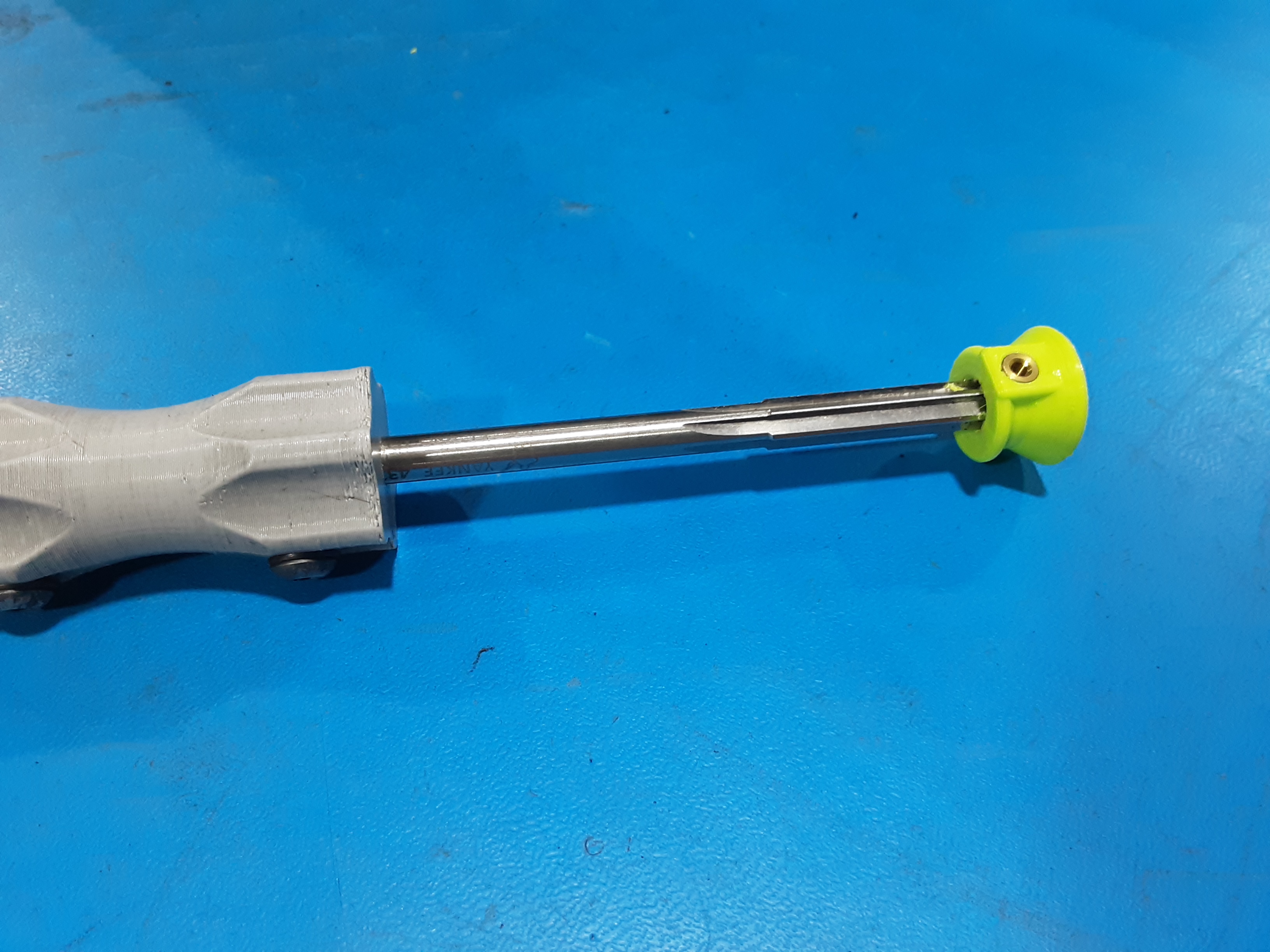
4A) Grab HD-RD0096 x1, PP-GP0824 x1, PP-GP0882 x1, PP-GP0587 Knob x1, and HD-BT0012 x1.
4B) Use ream to ensure the hole in PP-GP0824 is clear.
4C) Ream hole in PP-GP0882 so HD-RD0096 fits.
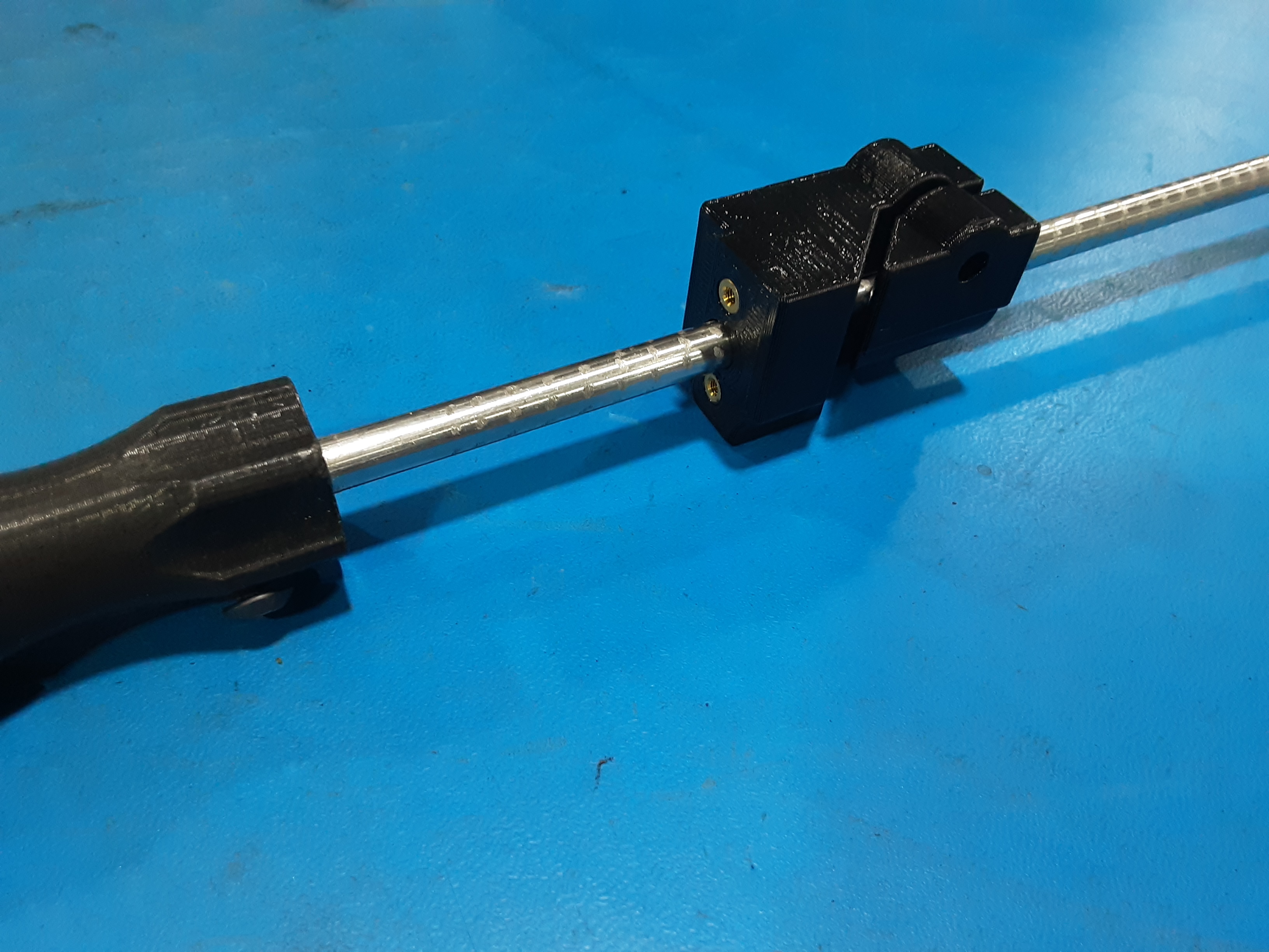
4D) Place PP-GP0882 flush on the end of HD-RD0096 and secure using HD-BT0012 x1.
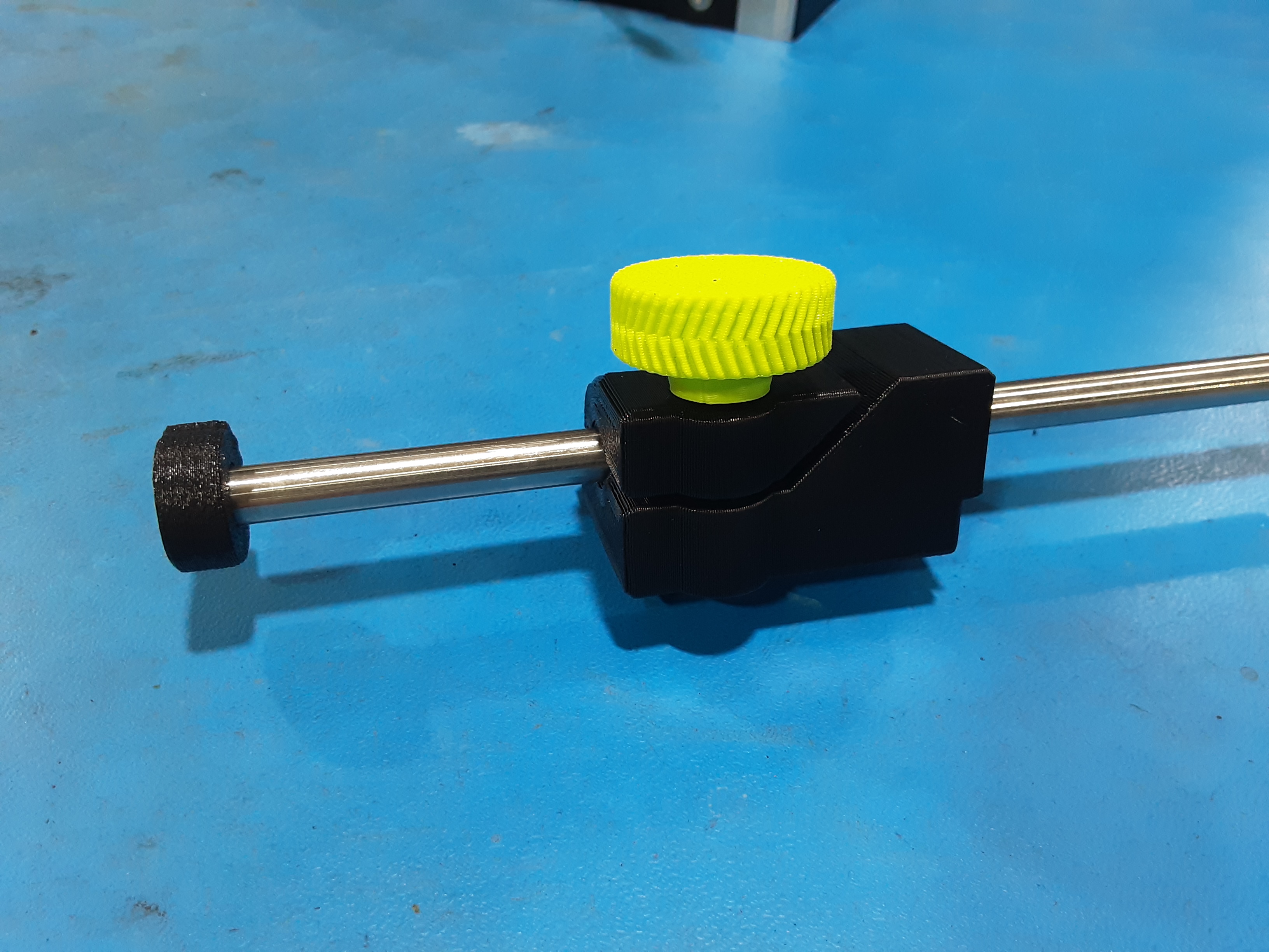
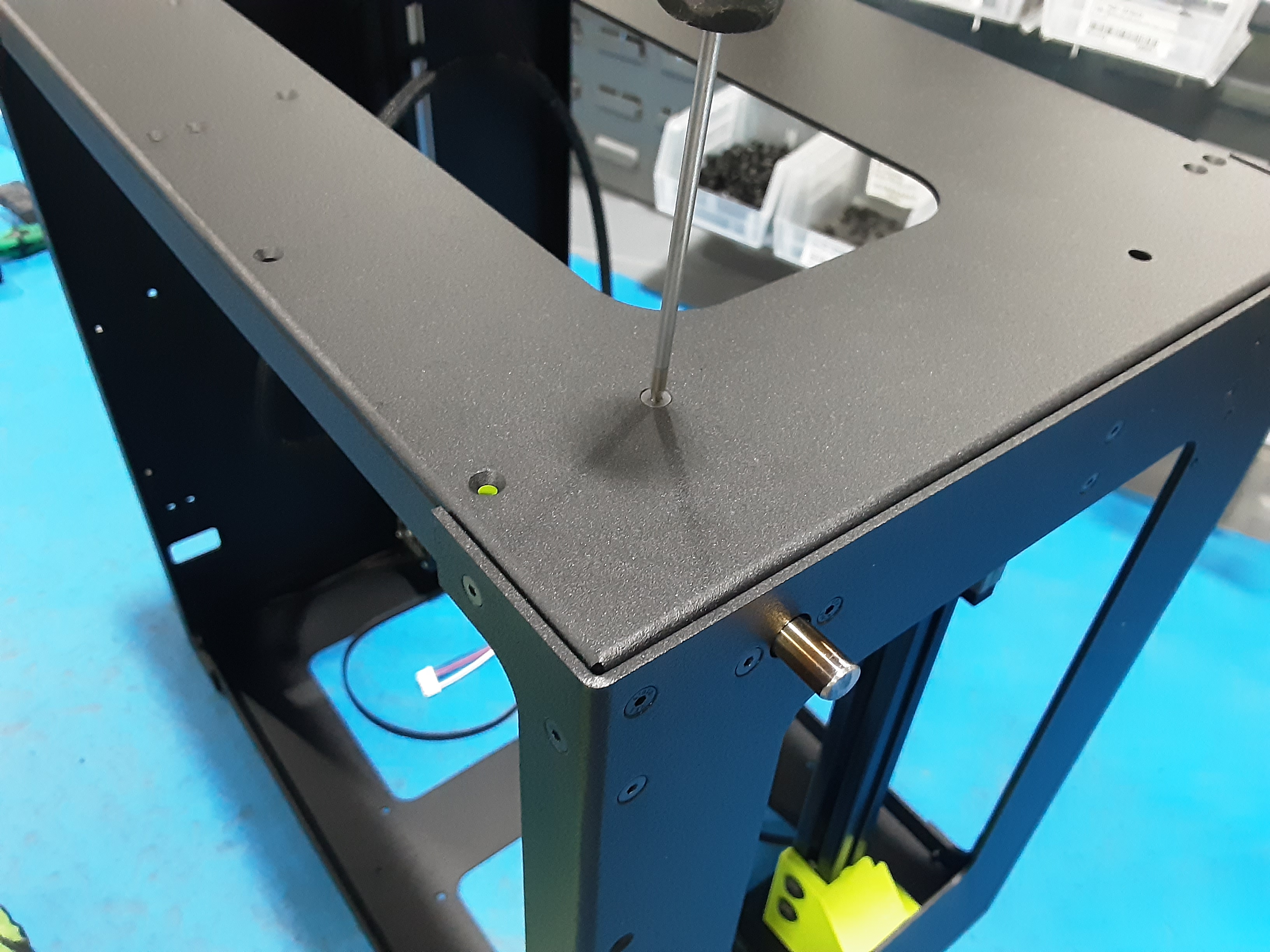
4E) Loosely install PP-GP0587 knob in PP-GP0824. Slide PP-GP0824 on HD-RD0096.
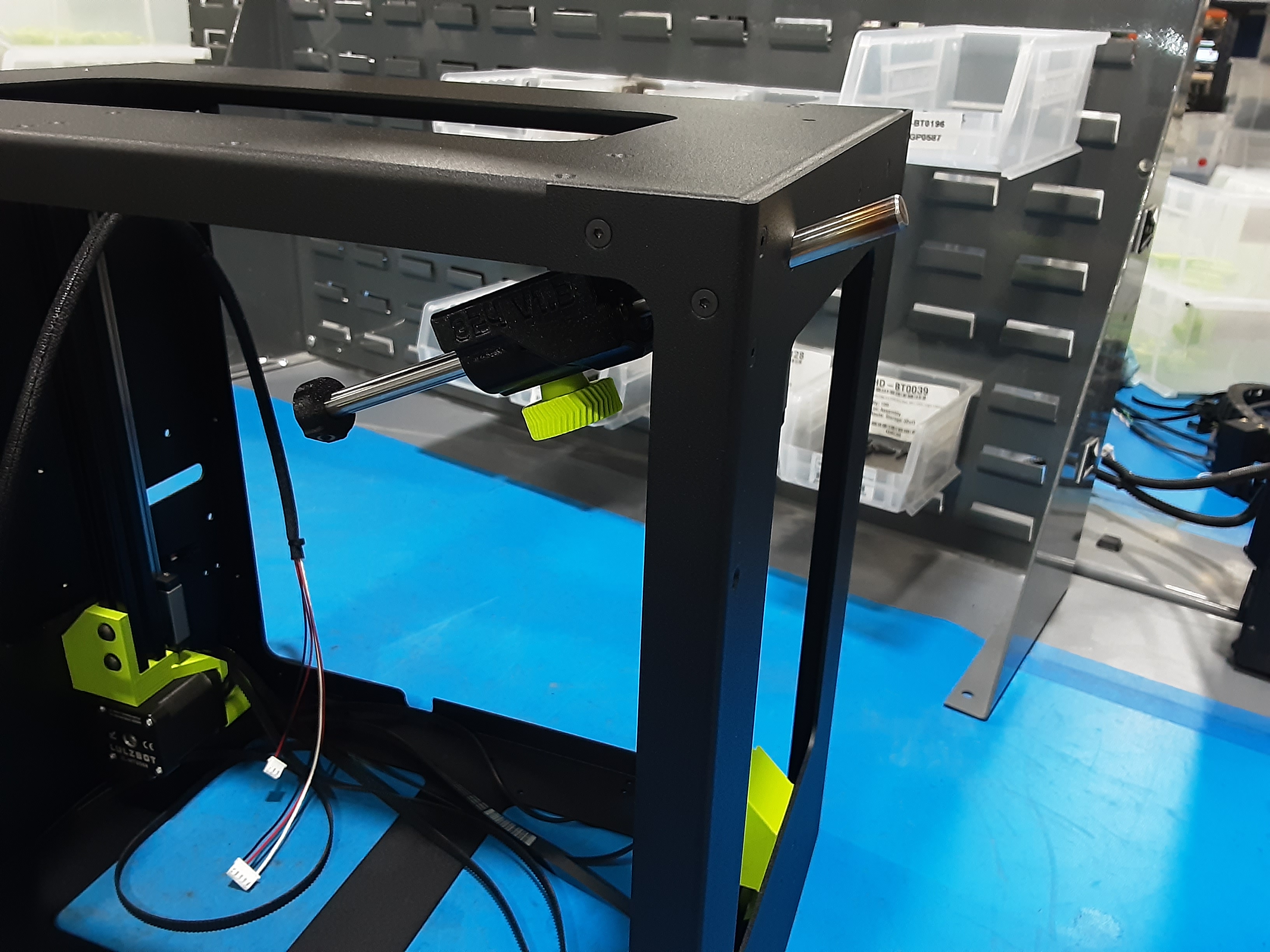
4F) Slide HD-RD0096 through the top hole on Z.L.R.
4G) Secure PP-GP0824 to Z.L.R. using HD-BT0128 x2.
4H) Secure PP-GP0824 to PP-FP0233 using HD-BT0128.
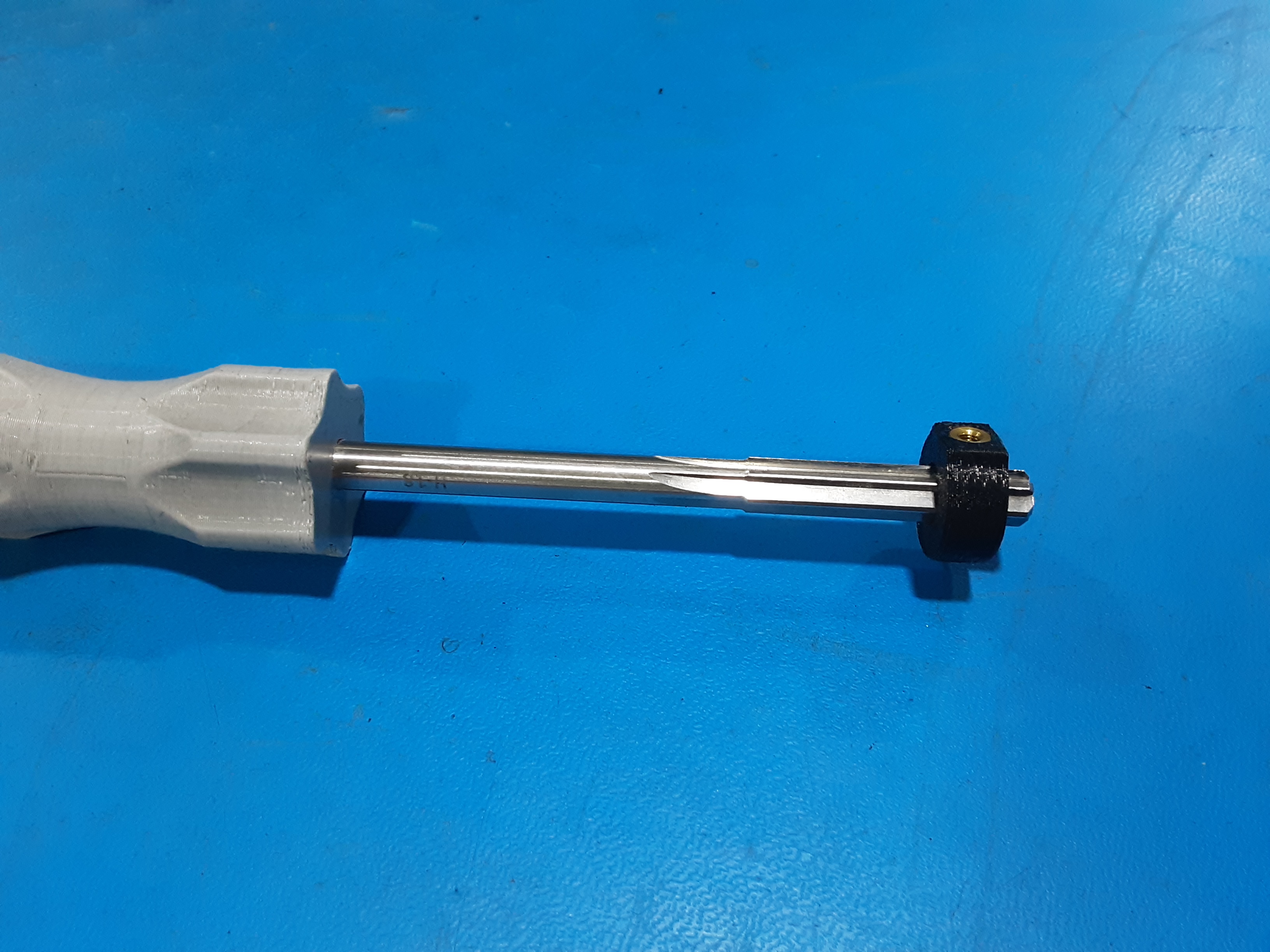
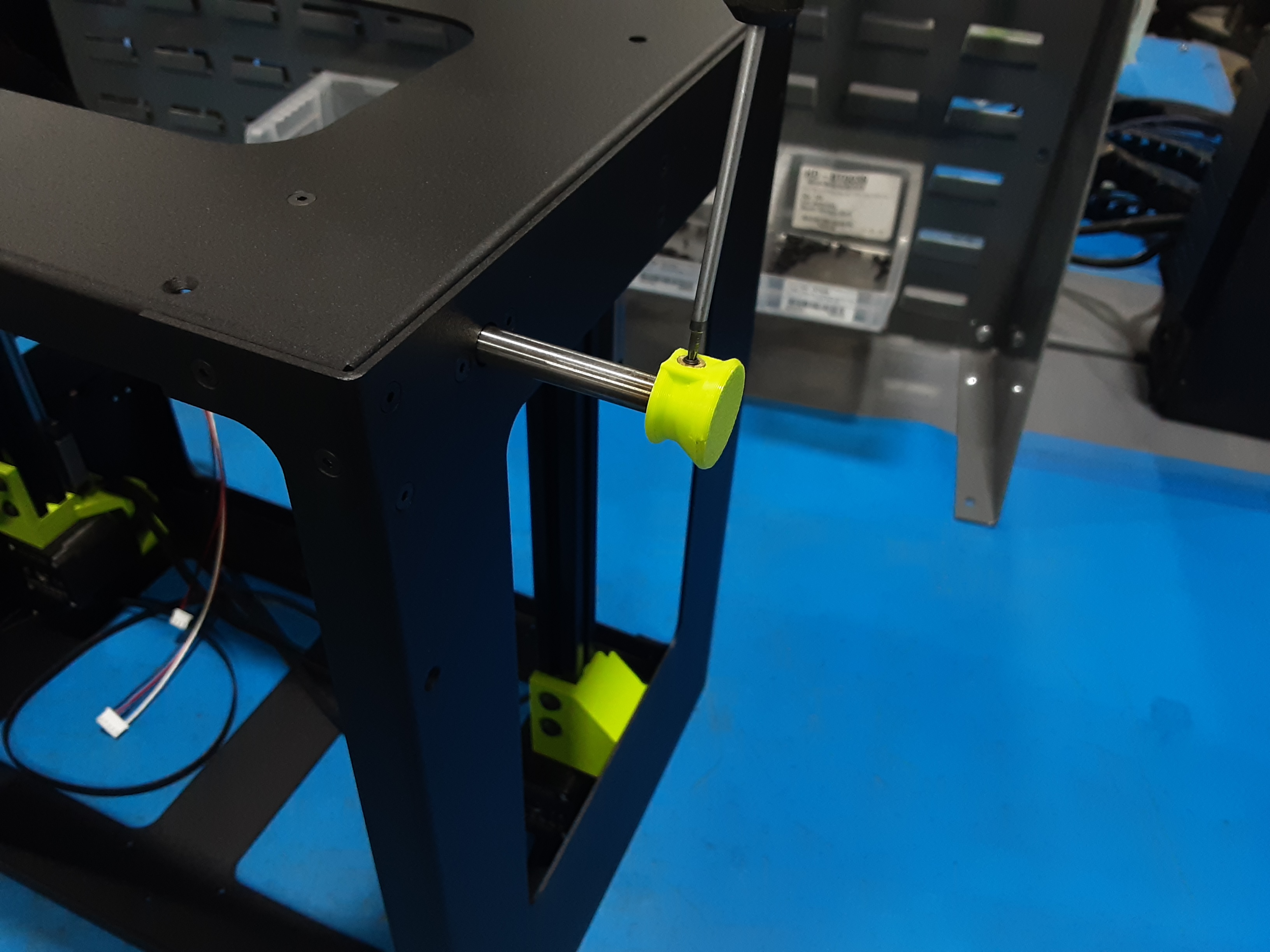
4I) Use ream to clean out the hole in PP-GP0835.
4J) Attach PP-GP0835 to HD-RD0096 and secure it using HD-BT0012 x1.
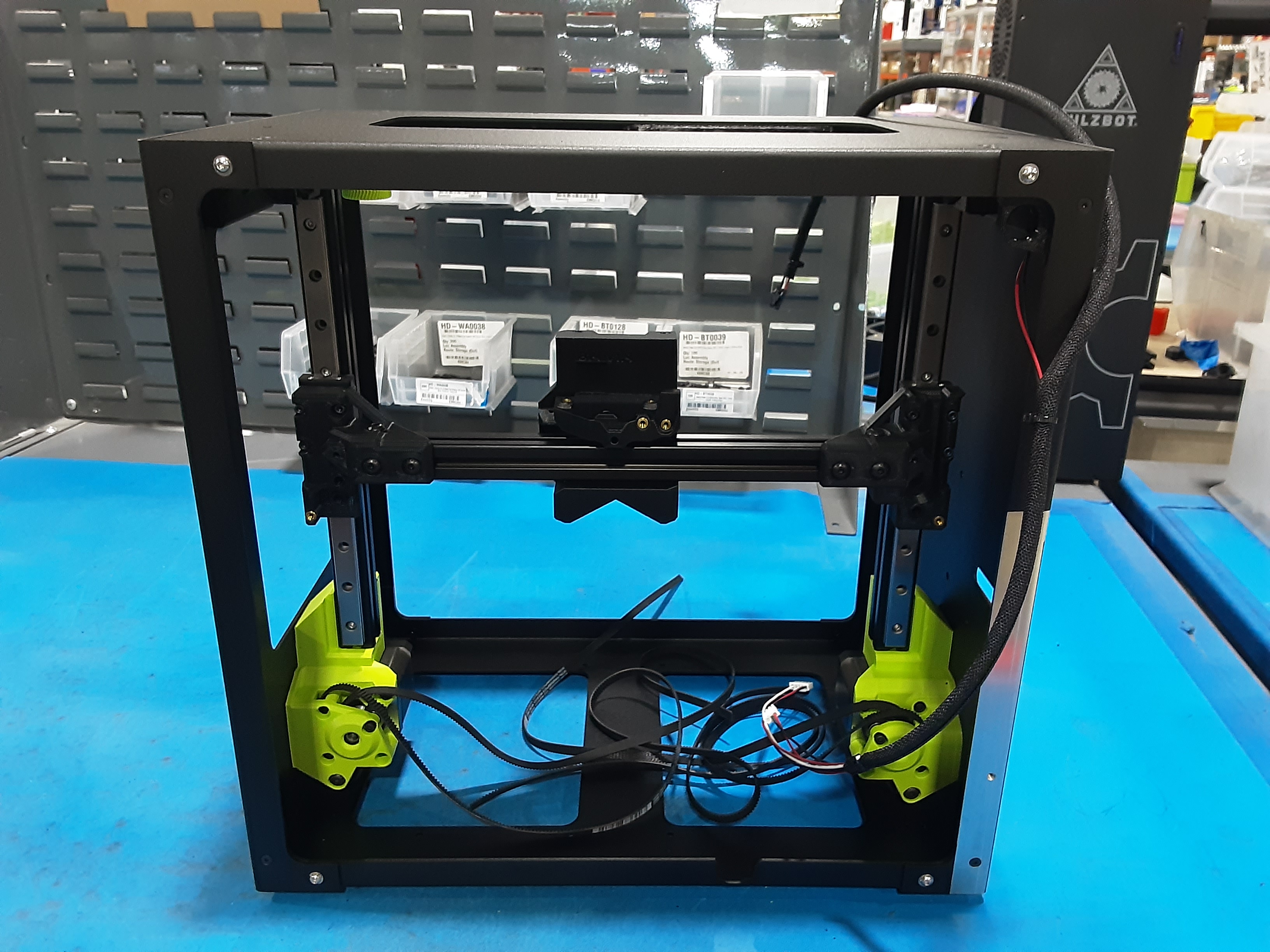
Final Steps
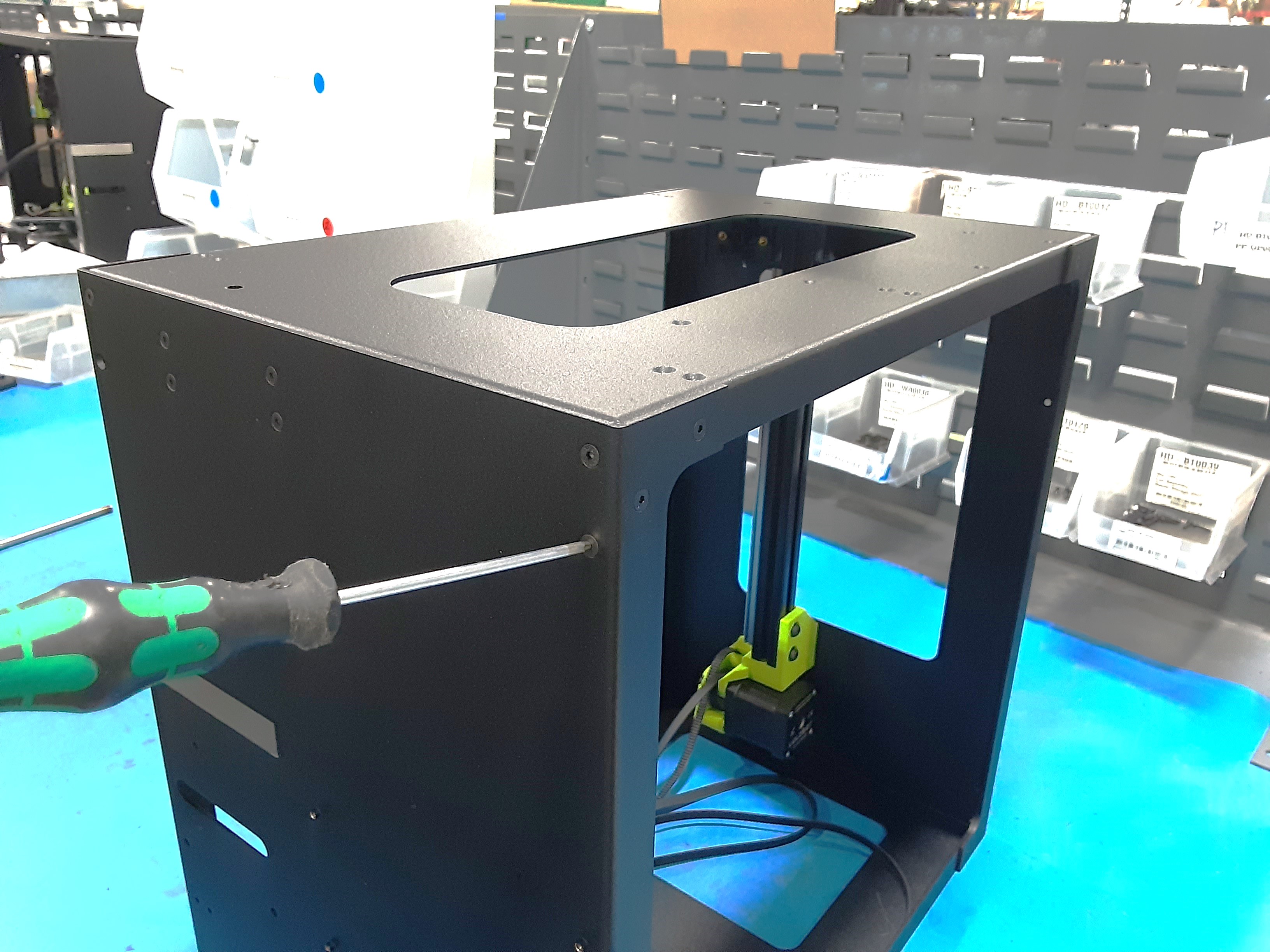
5A) Grab PP-GP0817 x1 and attach to PP-FP0233 using HD-BT0128 x2.
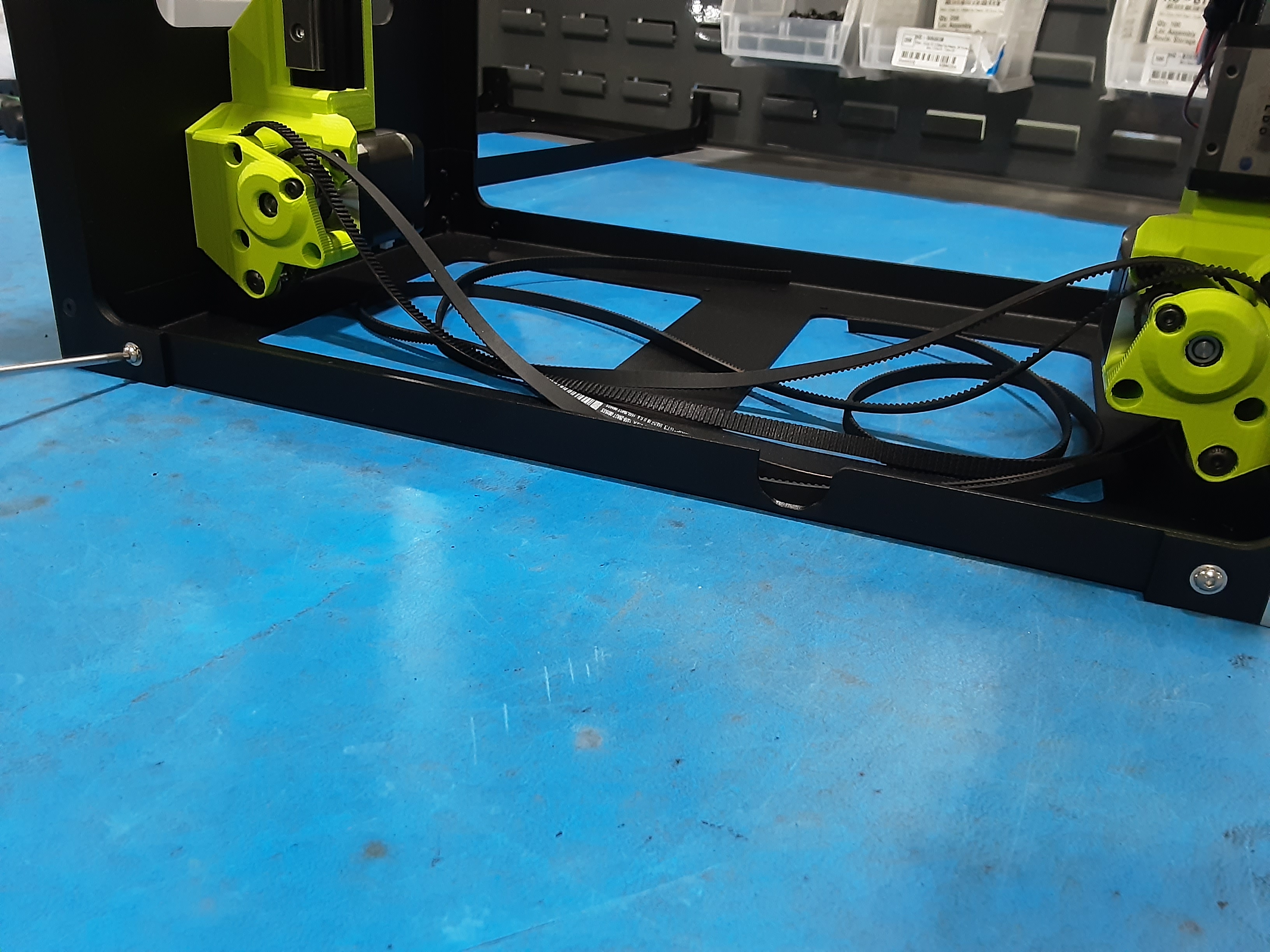
5B) Use corner feet jig to place HD-MS0054 on each corner of PP-FP0234 and Z.L.L.
5C) Place HD-MS0054 x2 on PP-FP0234 on the Z.L.R. side approximately as shown.
5D) Place two rubber bumpers in the rails of each Z.L.
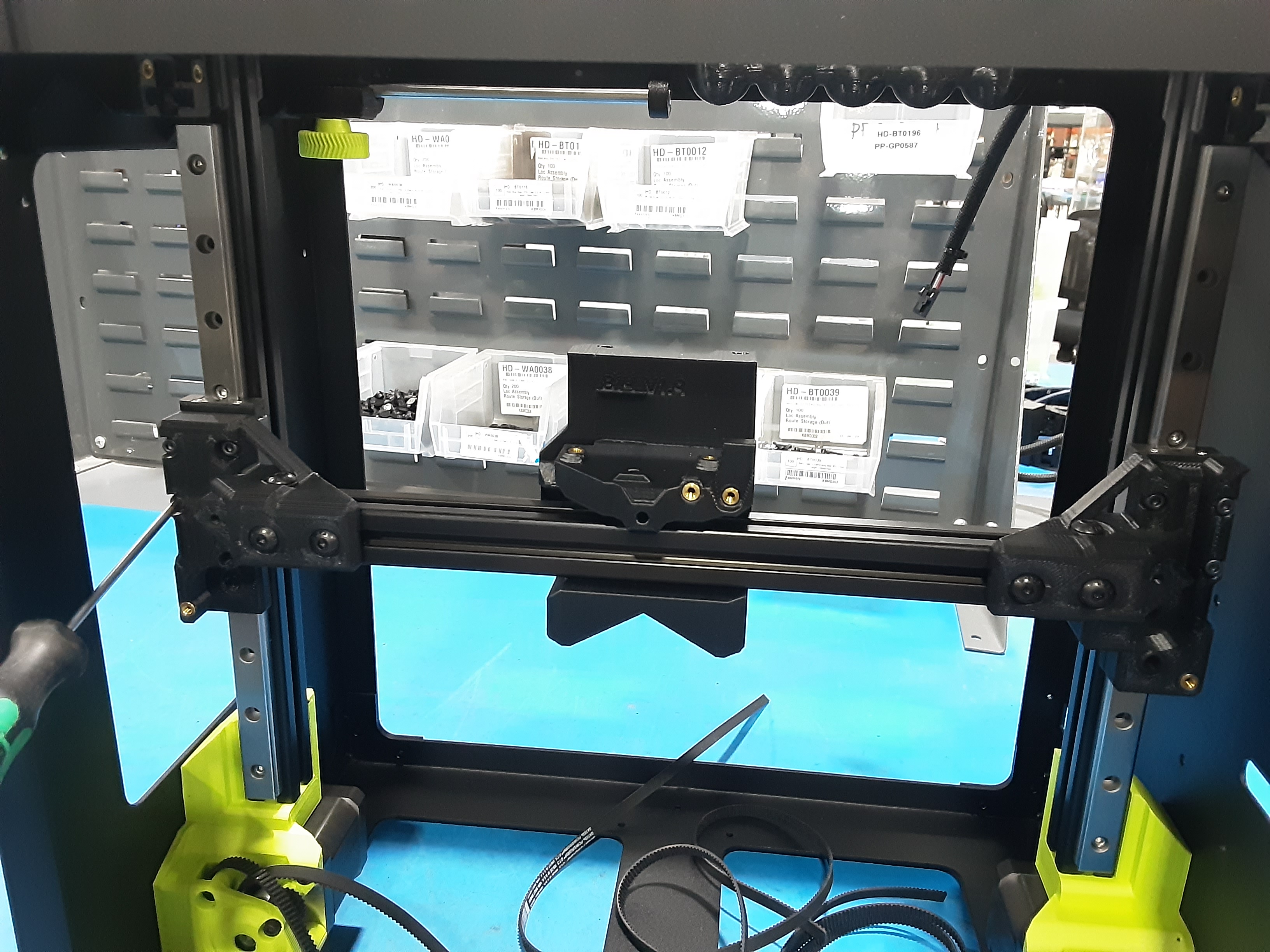
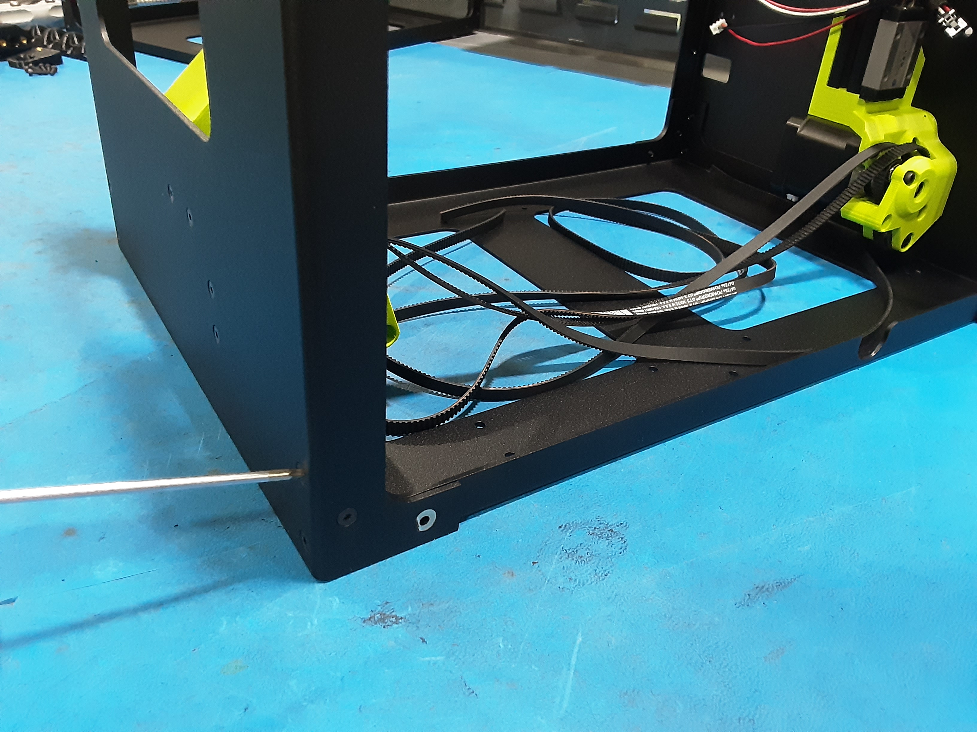
5E) Grab HD-BT0039 x6 and X.C.A.
5G) Line up the X.C.A. with the Z.L. trucks. Start to attach the X.C.A. to the Z.L. trucks using one HD-BT0039 on each side of the X.C.A.
5H) Finish attaching the X.C.A. to the Z.L. trucks using HD-BT0039 x4. Leave all HD-BT0039 slightly loose.