Open HardwareAssembly Instructions
Guides for installation and assembly of the LulzBot line of products made by FAME 3D LLC.
Guides for installation and assembly of the LulzBot line of products made by FAME 3D LLC.
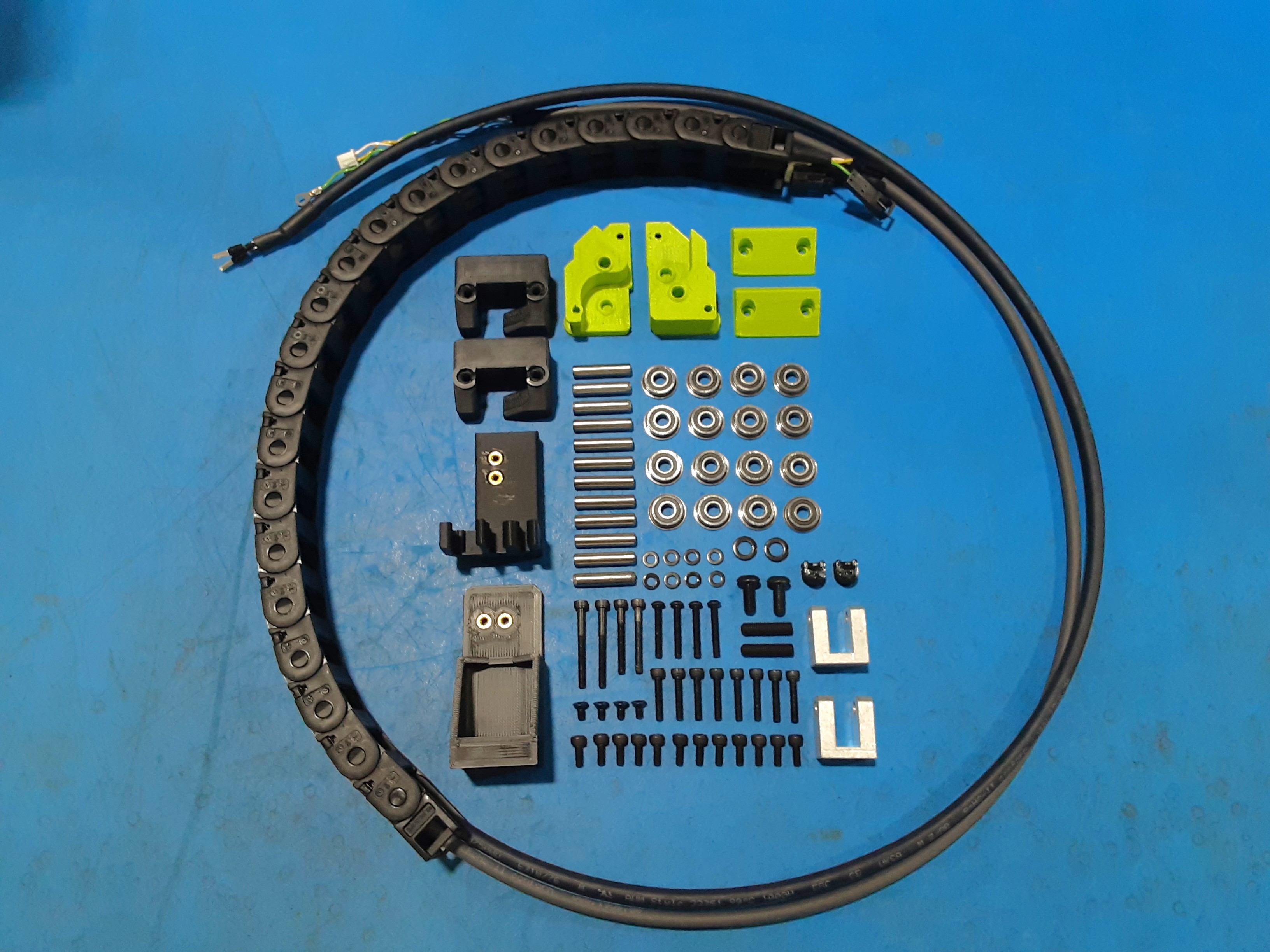
1x [AS-CB0218] Mini3, Bed Harness
2x [HD-BT0041] Metric Class 12.9 SHCS Alloy Steel, M3 x 25mm Length, 0.50mm Pitch
2x [HD-BT0042] Metric Class 12.9 SHCS Alloy Steel, M3 x 30mm Length, 0.50mm Pitch
4x [HD-BT0128] M3 x 6mm FHCS Black-Oxide
12x [HD-BT0157] Class 12.9 Alloy Steel Black-Oxide SHCS, M3 x 8mm Length, 0.50mm Pitch
2x [HD-BT0158] Class 10.9 Steel BHCS, M5 x 12mm Length, .8 mm Pitch
4x [HD-BT0171] Class 10.9 Black-Oxide Steel BHCS M3 x 20mm Length, .5mm Pitch
8x [HD-BT0185] Black-Oxide Alloy Steel SHCS M3 x 16mm Long, 0.5mm Thread
2x [HD-BT0301] M5 x 0.8 x 20mm Black Set Screw
16x [HD-BU0035] Flanged Bearing 695-2RS
12x [HD-RD0093] 4.95mm x 24mm Dowel, SS
8x [HD-WA0038] Black-Oxide 18-8 Steel Flat Washer, M3 Screw Size, 3.2mm ID, 7.0mm OD
2x [HD-WA0040] Black-Oxide 18-8 Stainless Steel Washer, M5 Size, 5.3mm ID, 10.0mm OD
1x [PP-GP0801] Mini3, Y Chain to Frame, ABS-BLK
1x [PP-GP0805] Mini3, Y Chain to Bed, ABS-BLK
1x [PP-GP0813] Mini3, Z Cap Right, ABS-GRN
2x [PP-GP0816] Mini3, X Belt Clamp, ABS-BLK
1x [PP-GP0819] Mini3, Z Cap Left, ABS-GRN
2x [PP-GP0826] Mini3, Z Tension Clamp, ABS-BLK
2x [PP-GP0899] Mini3 X Carriage Belt Press
2x [PP-MP0360] XZ Idler Yoke Aluminum Rev 0-4
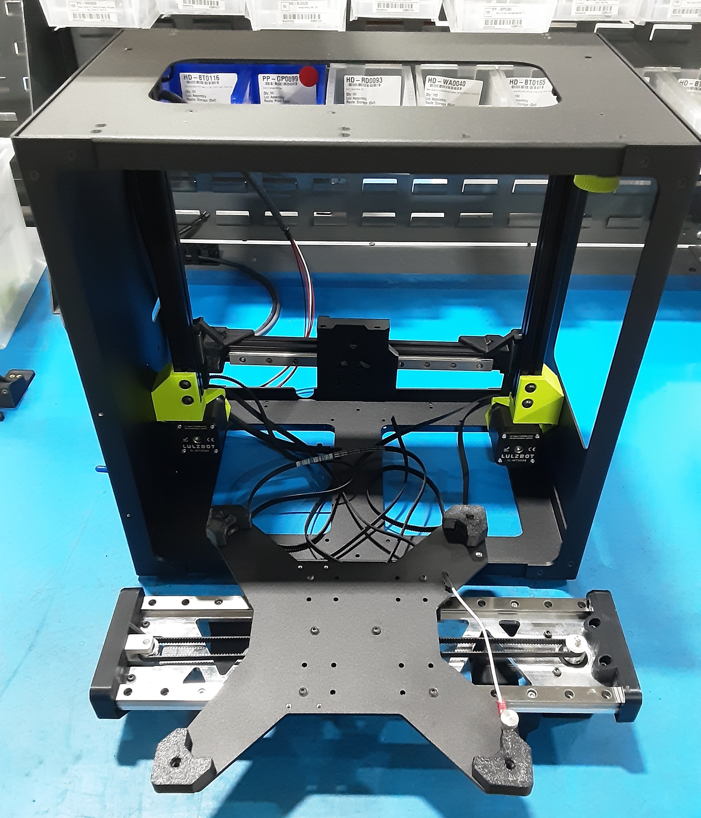
Frame Assembly
Y Axis Bed Assembly (Y.A.B.)
X.C.A. Additions
2A) Grab the F.A. and remove the X.C.A.
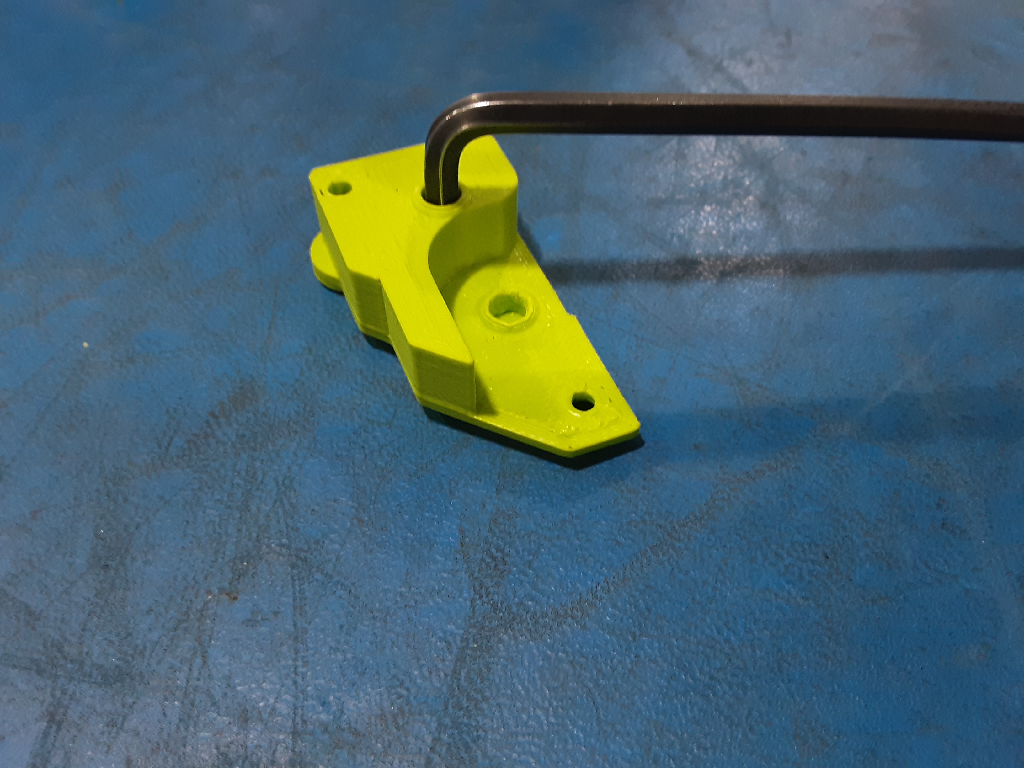
2B) Use a 4.5mm allen wrench to clean out holes for HD-RD0093s.
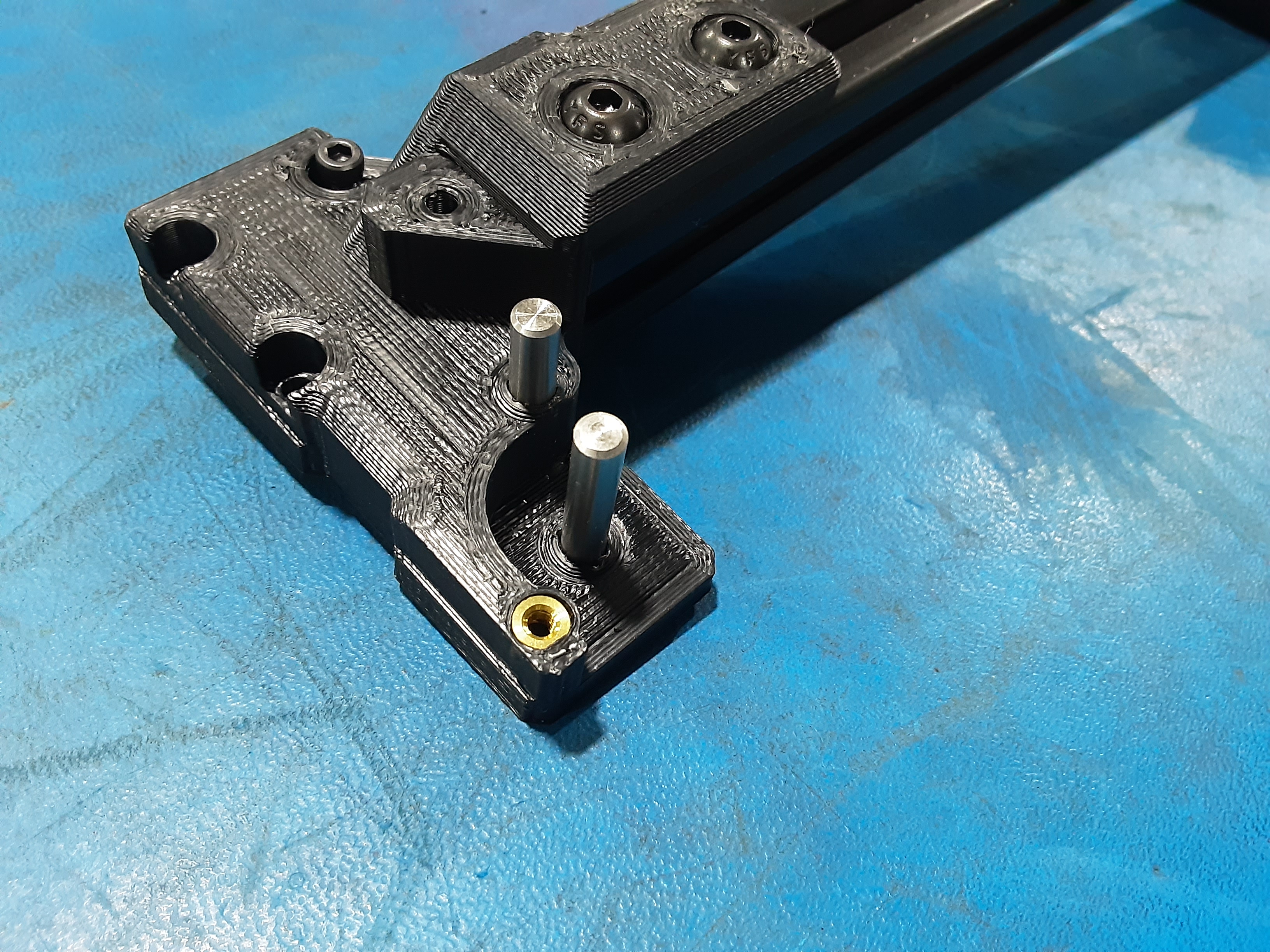
2C) Clean out two holes for HD-MS0093 on PP-GP0811 from X.C.A. and install HD-MS0093 x2
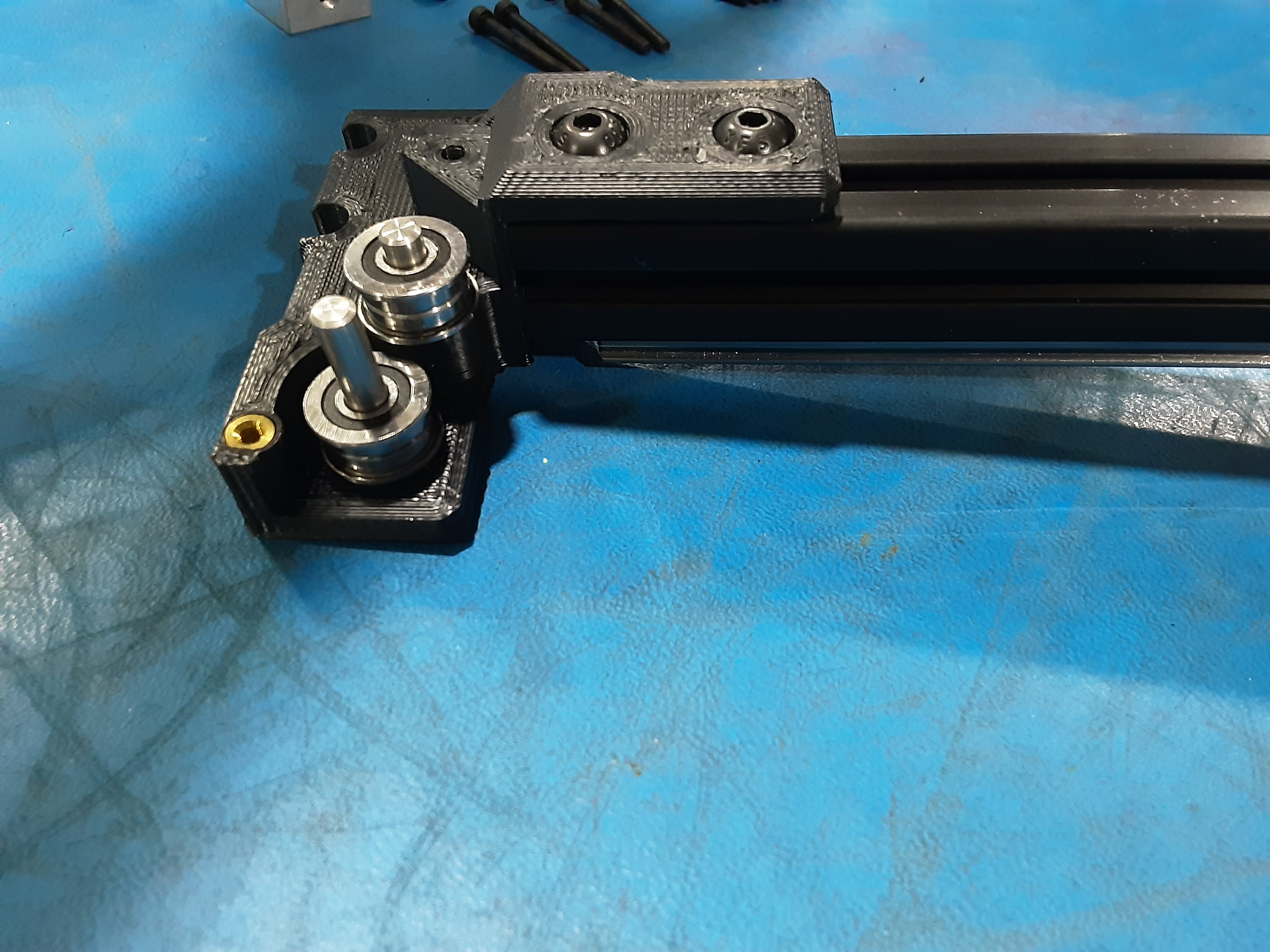
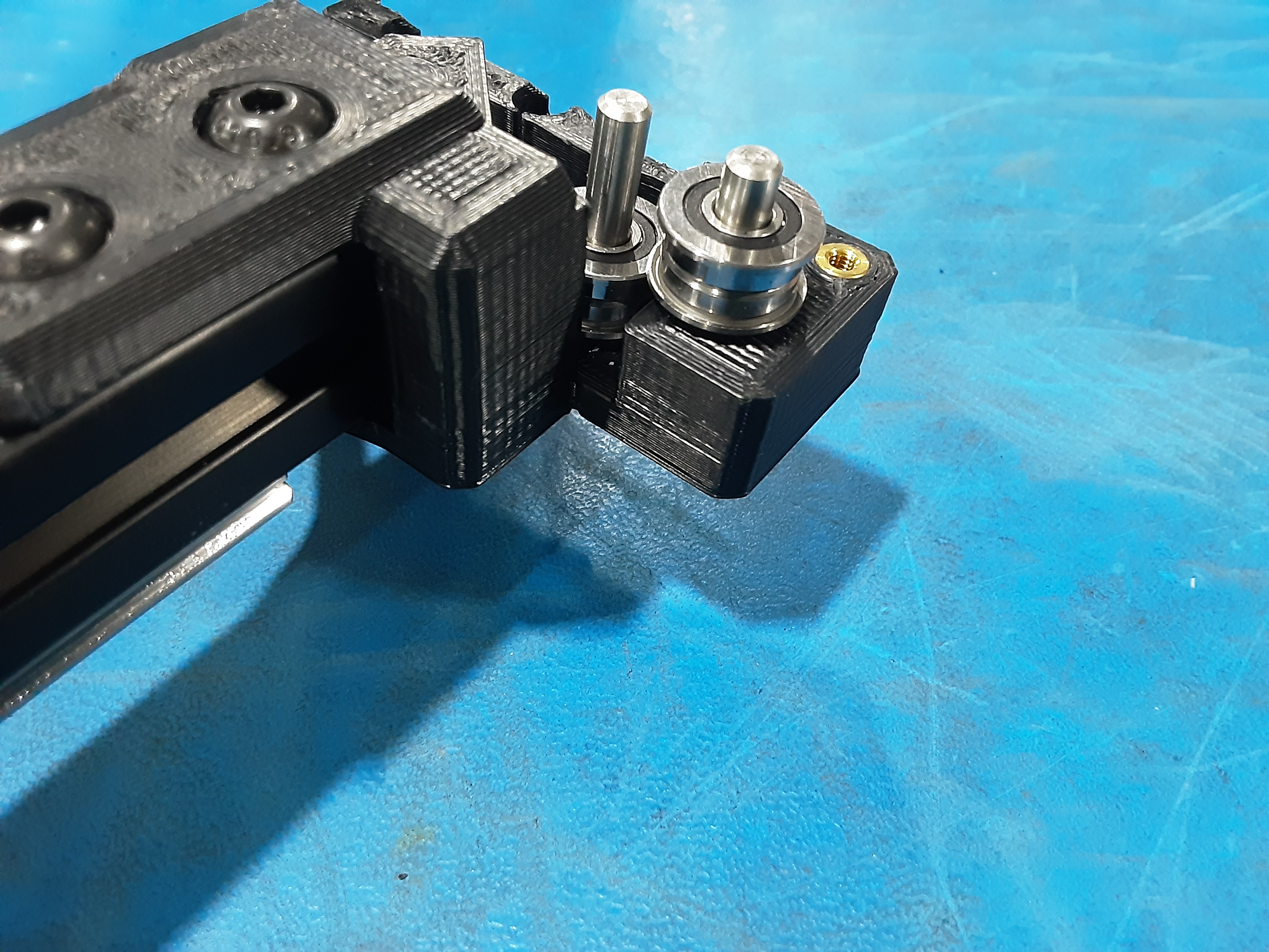
2D) Position the smaller sides of HD-BU0035 x2 together and place them on each HD-MS0093.
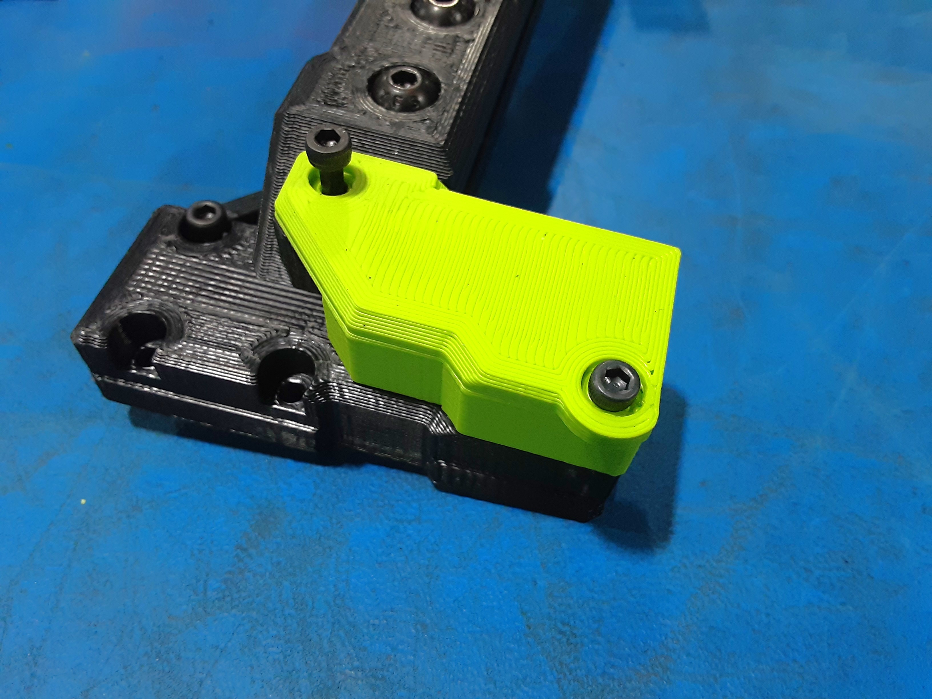
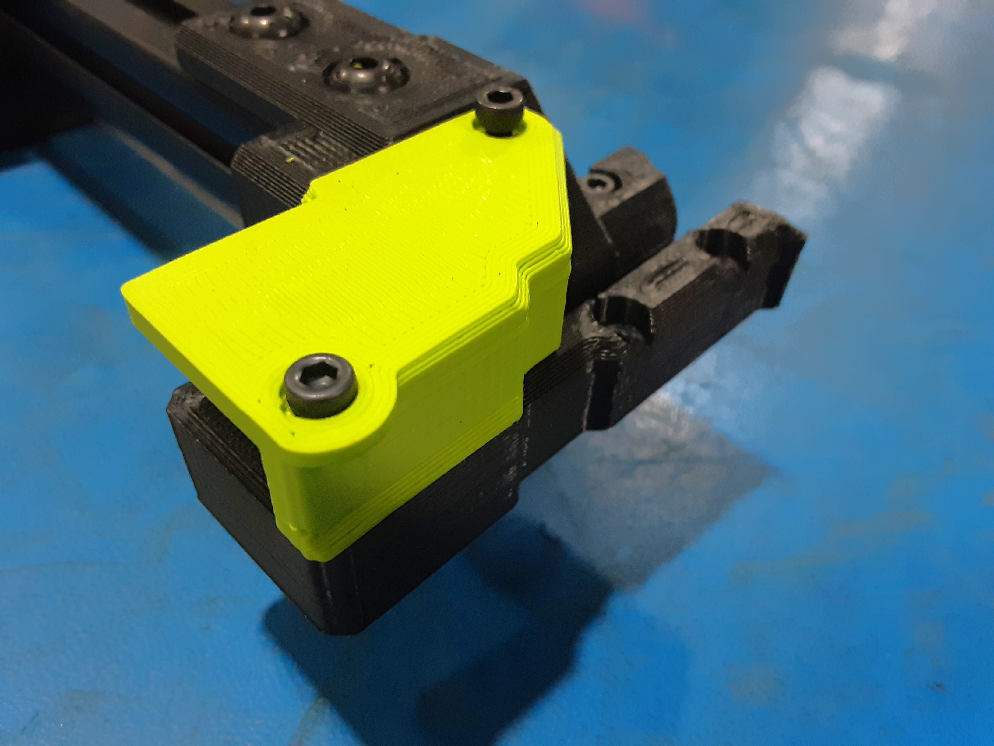
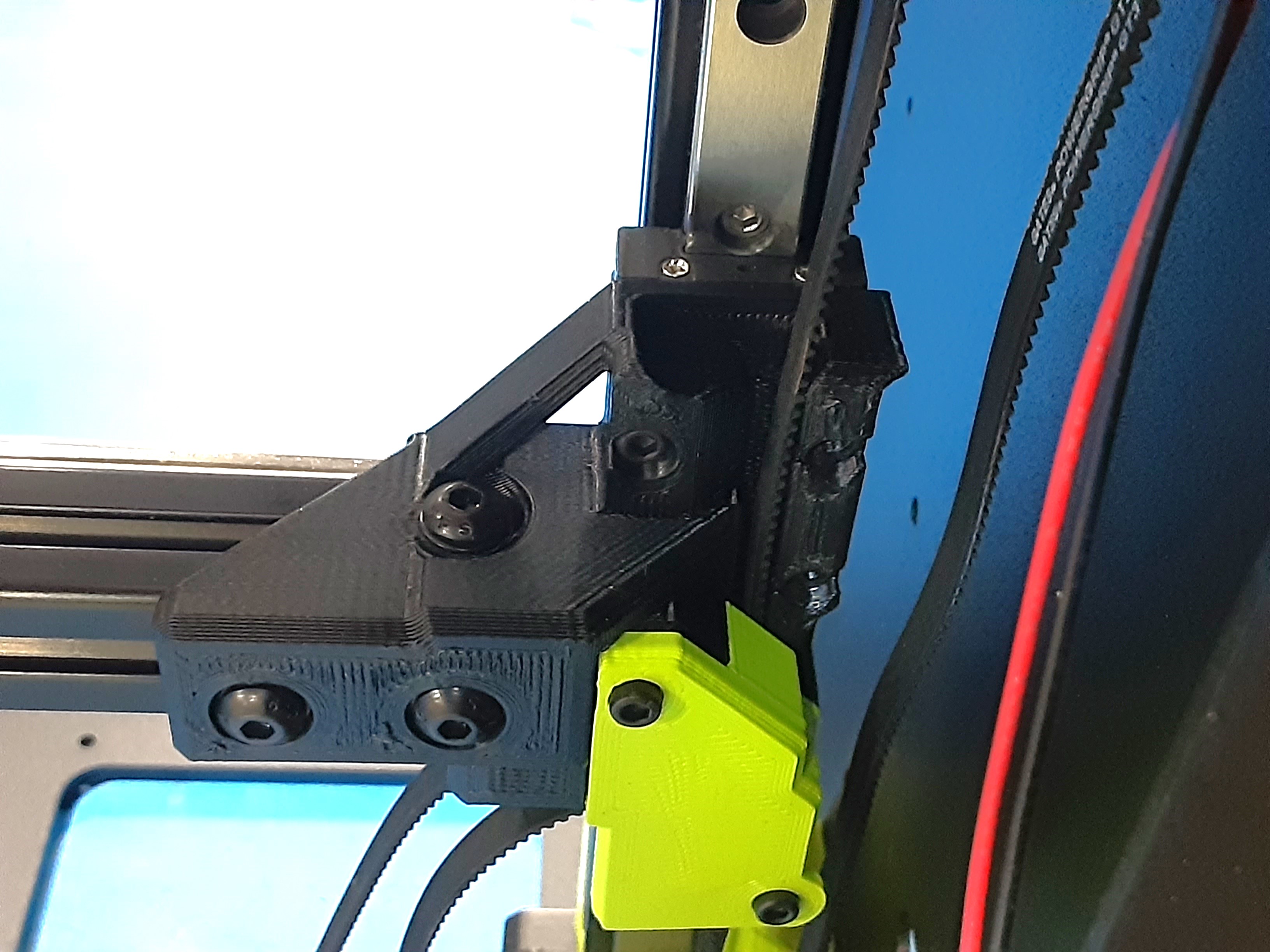
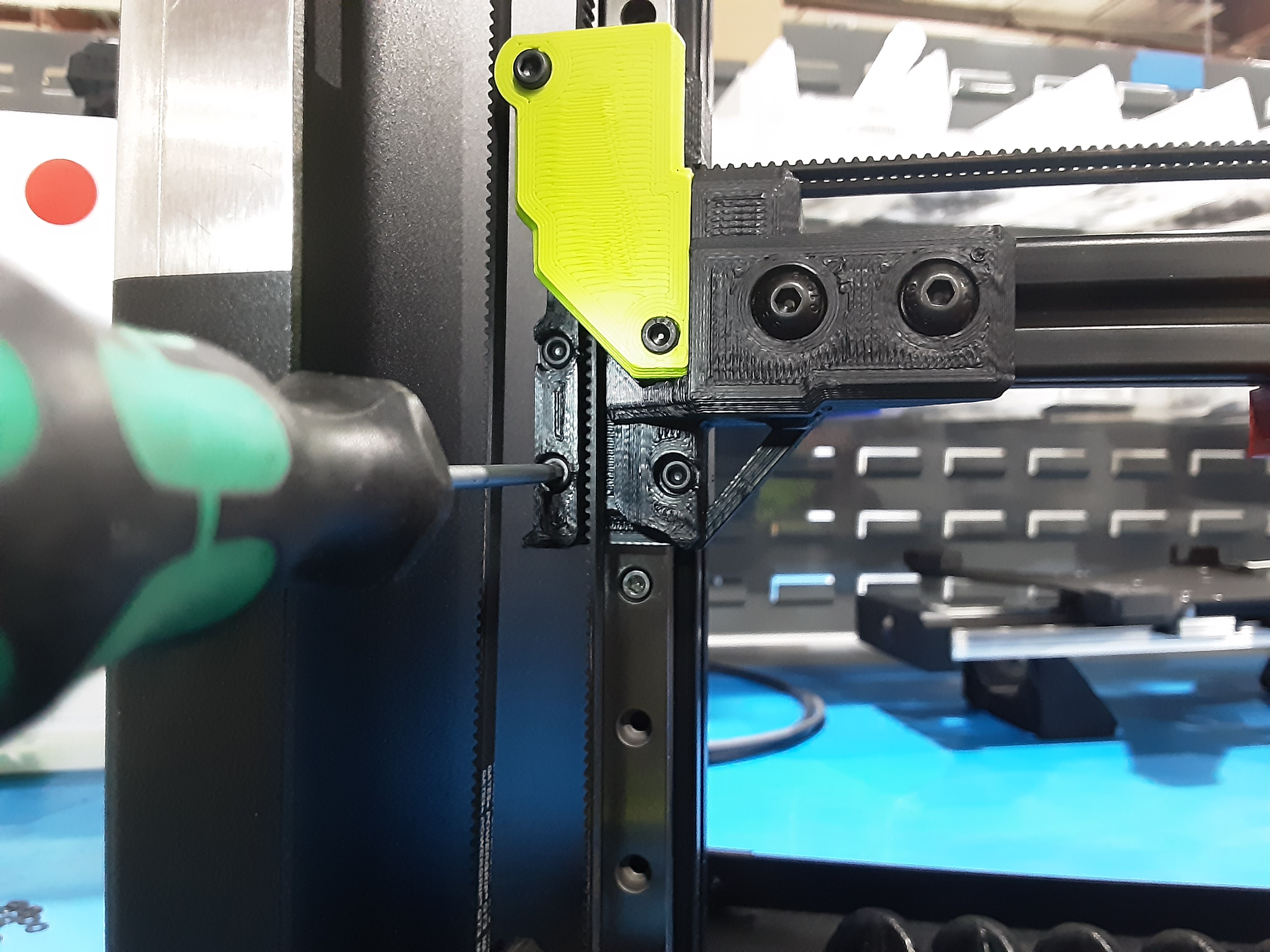
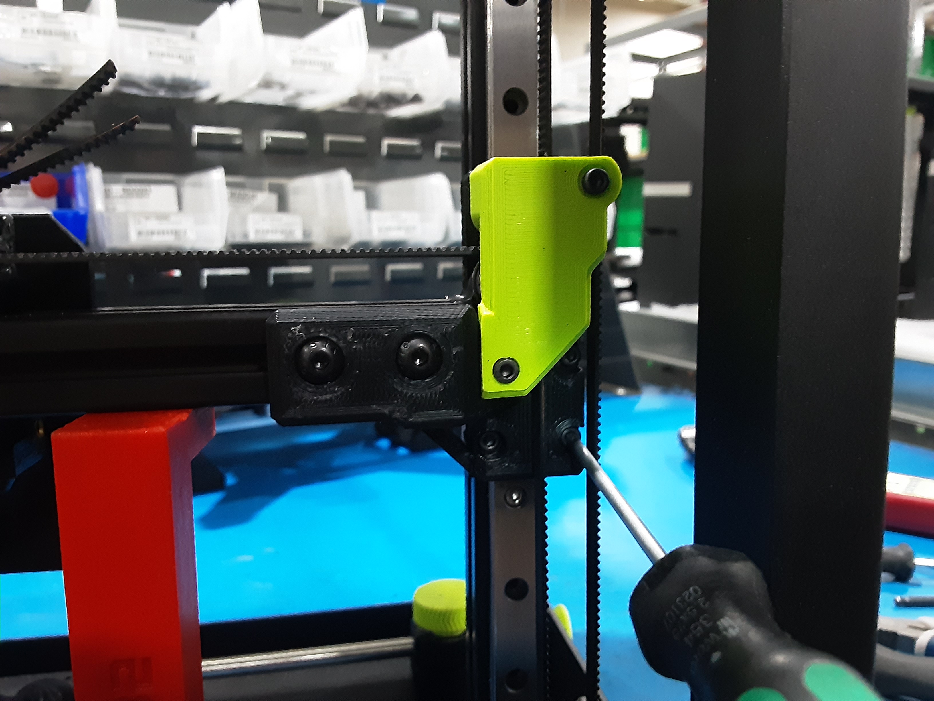
2E) Clean out two holes for HD-MS0093 on PP-GP0813 and place on PP-GP0811 from X.C.A. securing with HD-BT0185 x1. Place HD-BT0042 in the other hole.
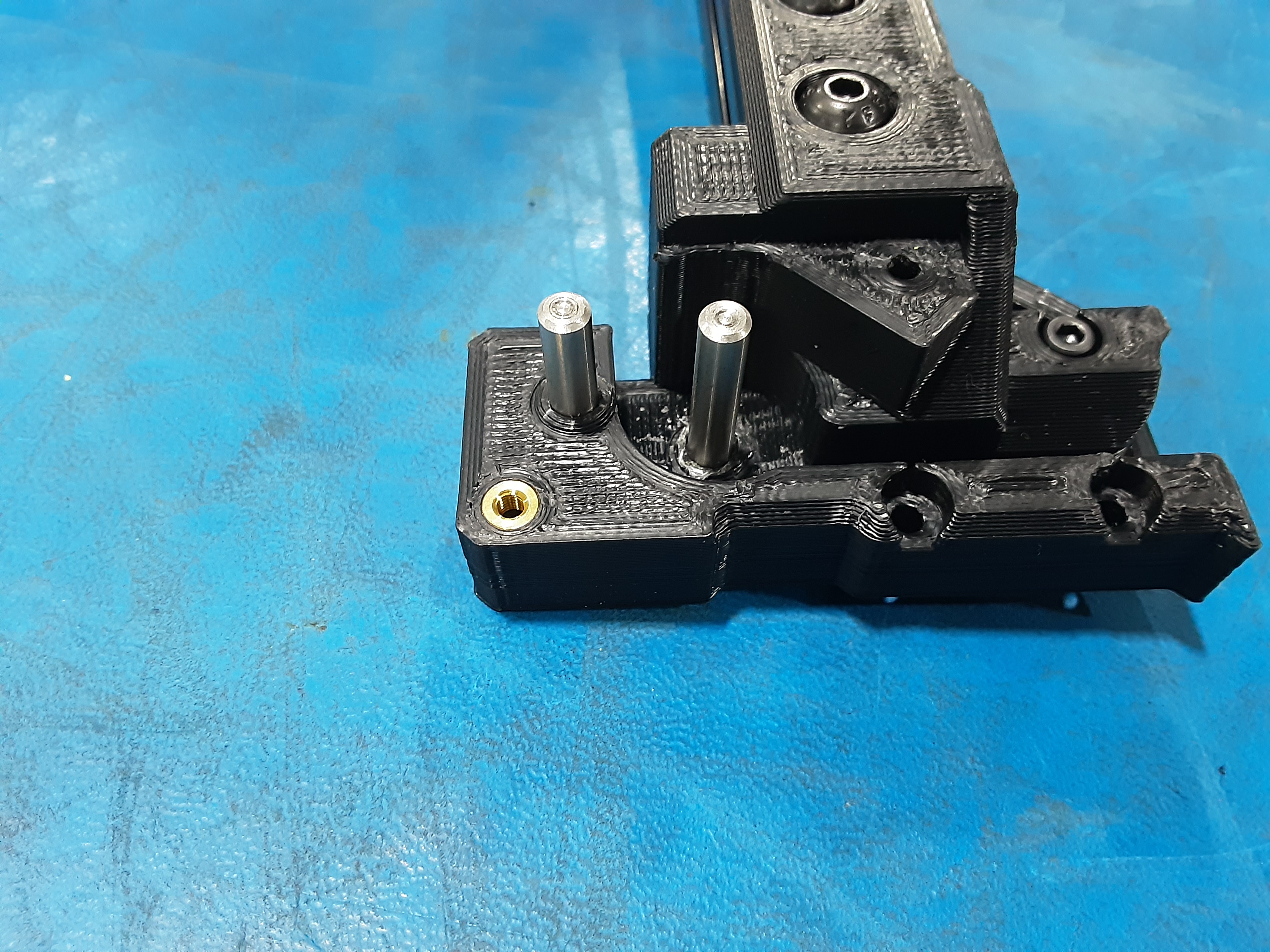
2F) Clean out two holes for HD-MS0093 on PP-GP0812 from X.C.A. and install HD-MS0093 x2
2G) Position the smaller sides of HD-BU0035 x2 together and place them on each HD-MS0093.
2H) Clean out two holes for HD-MS0093 on PP-GP0819 and place on PP-GP0812 from X.C.A. securing with HD-BT0185 x1. Place HD-BT0042 in the other hole.
2I) Reattach the X.C.A. using the pre-existing bolts and the placed HD-BT0042 x2.
2J) Place one rubber bumper in the fourth hole from the bottom on each Z.L. rod.
Z.L. Belting
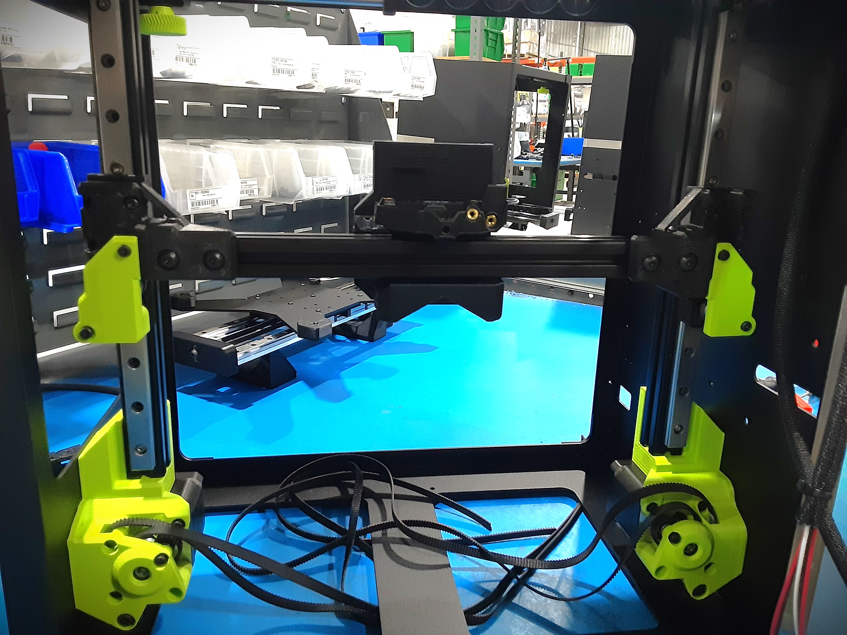
3A) Loop the part of the belt coming from the Z.L.R. motor gear around the bottom HD-BU0035s on the X.C.A.
3B) Loop the part of the belt coming from the Z.L.L. motor gear around the bottom HD-BU0035s on the X.C.A.
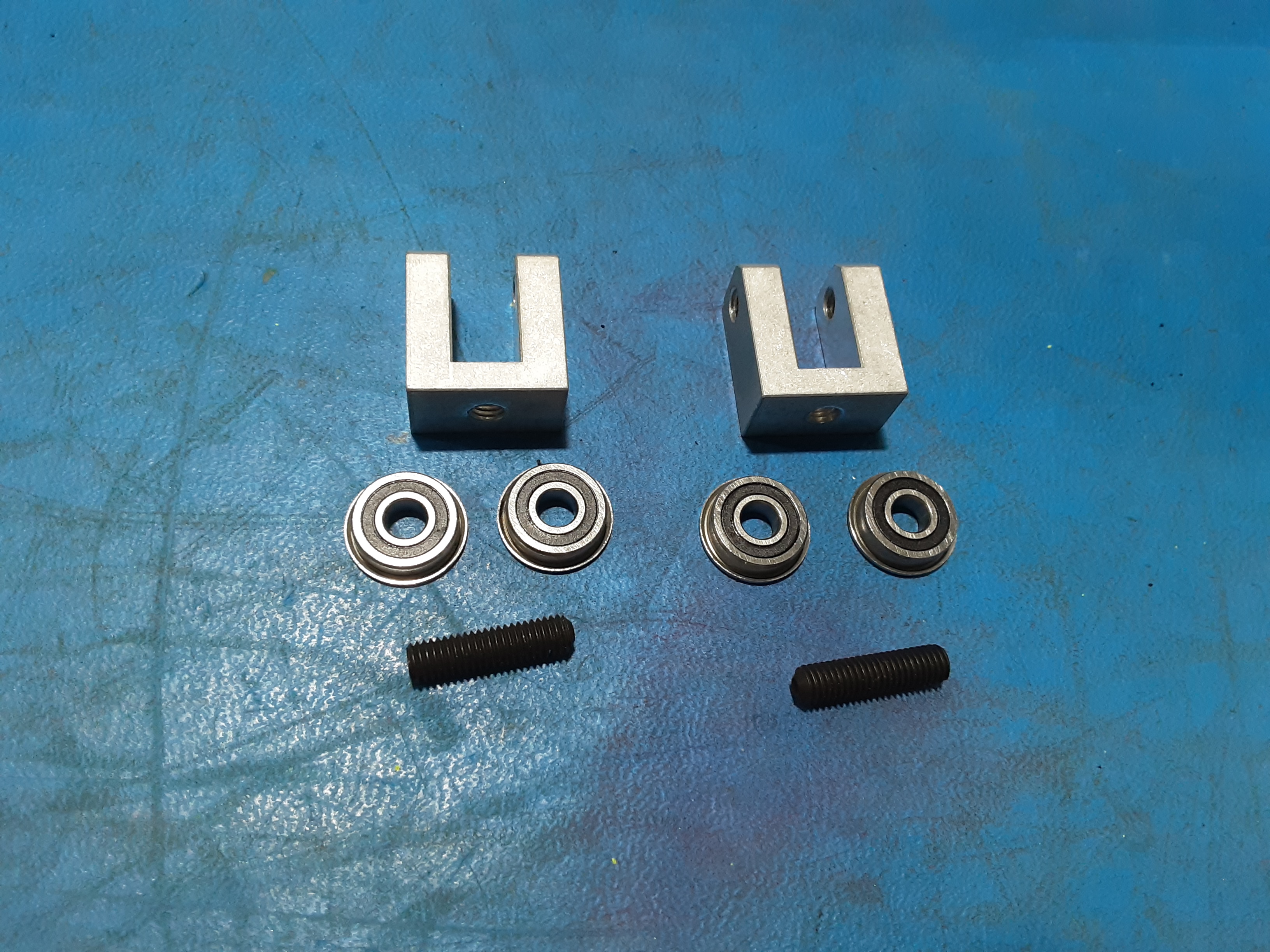
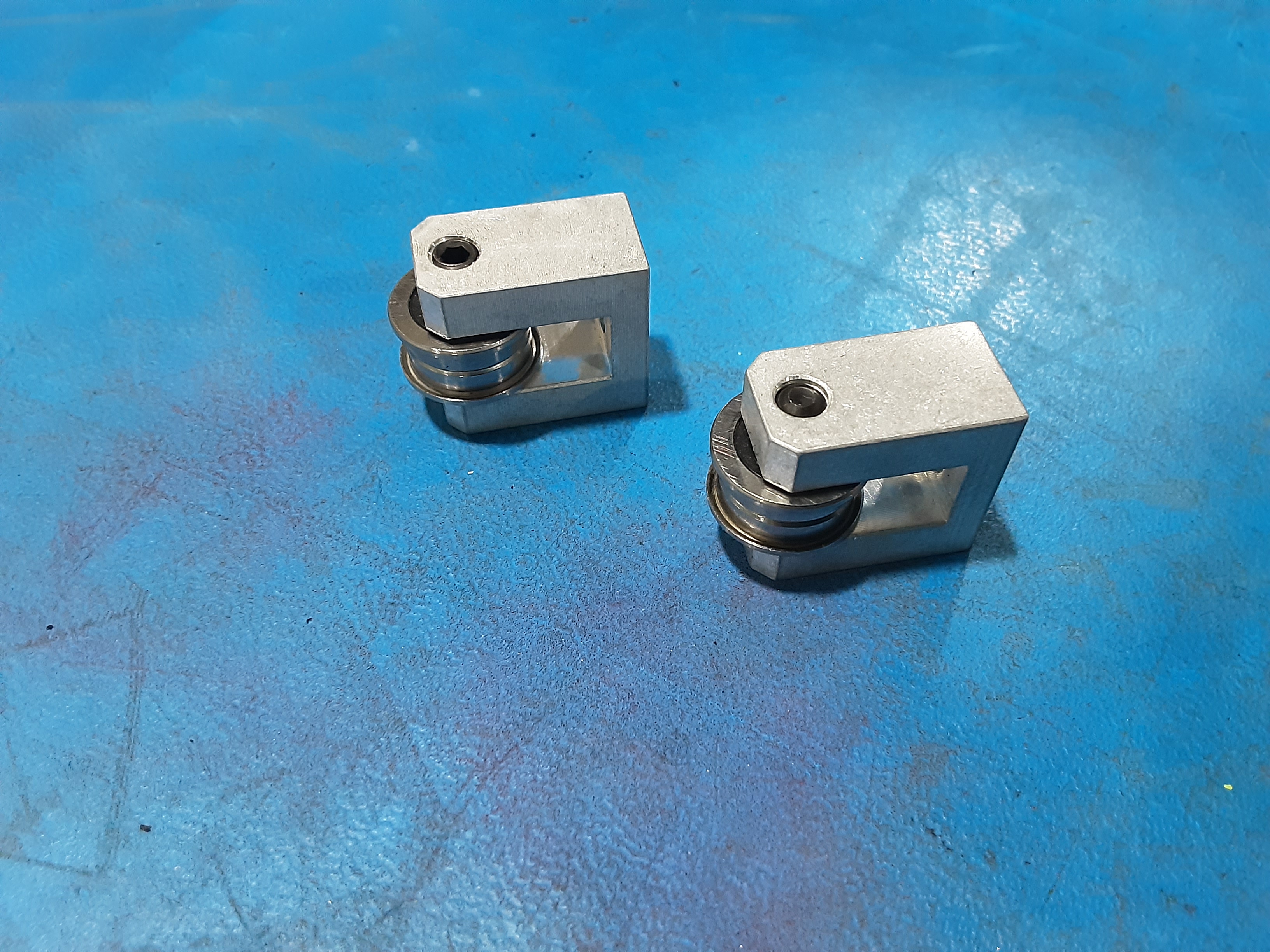
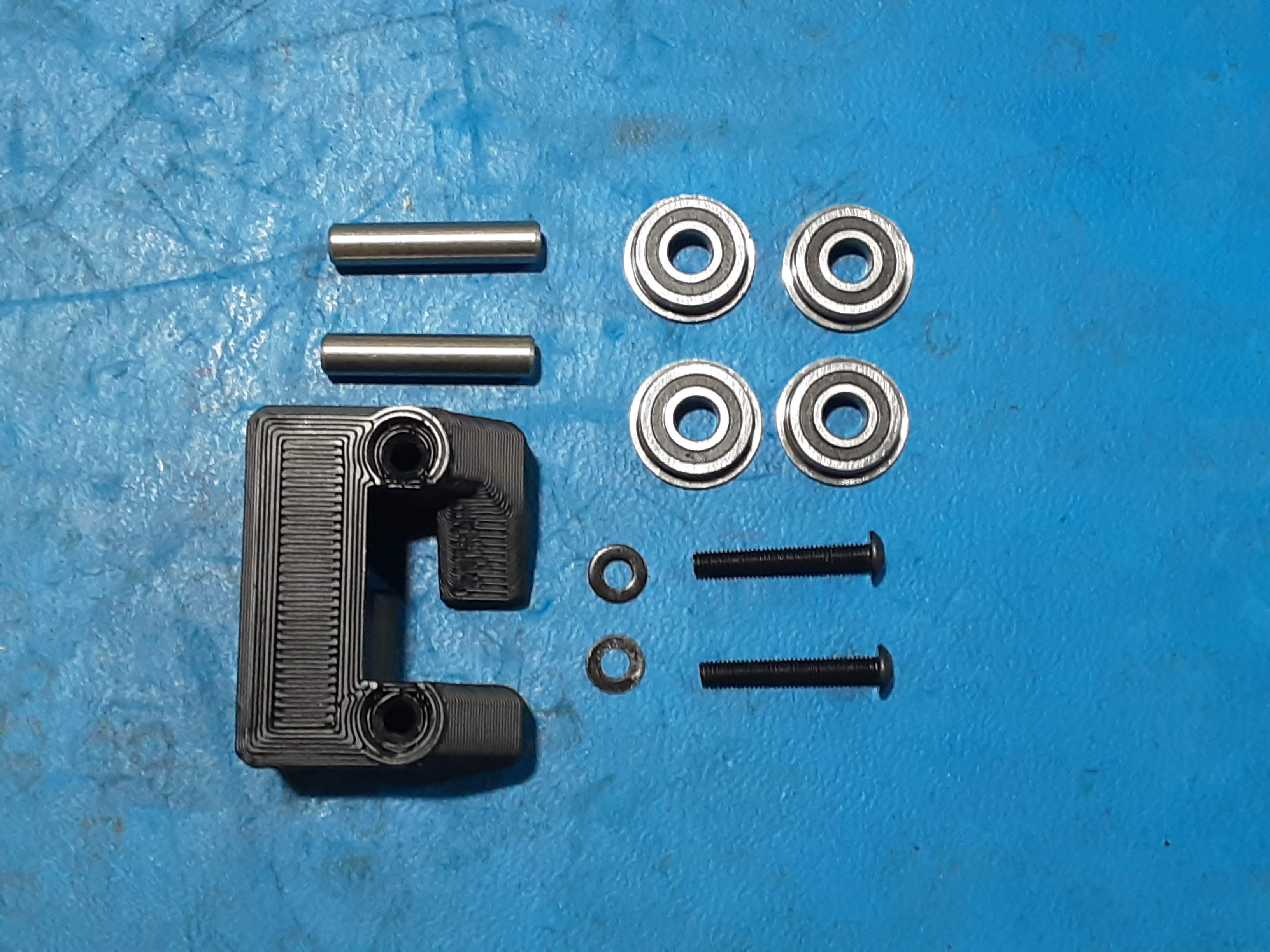
3C) Grab PP-MP0360 x2, HD-BU0035 x4, and HD-BT0301 x2.
3D) Position the smaller sides of HD-BU0035 x2 together and place them in PP-MP00360 and secure using HD-BT0301 x1. Make two.
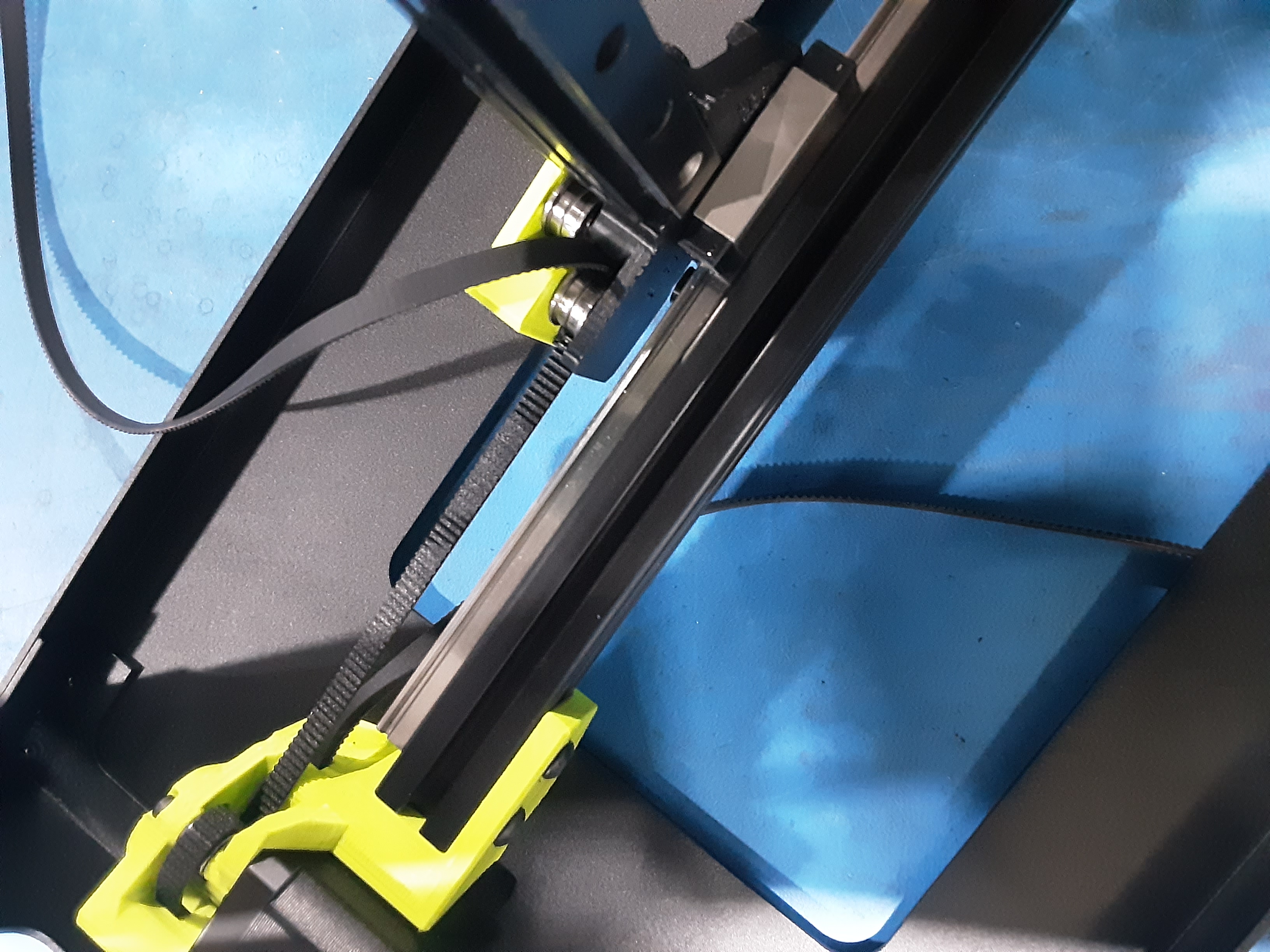
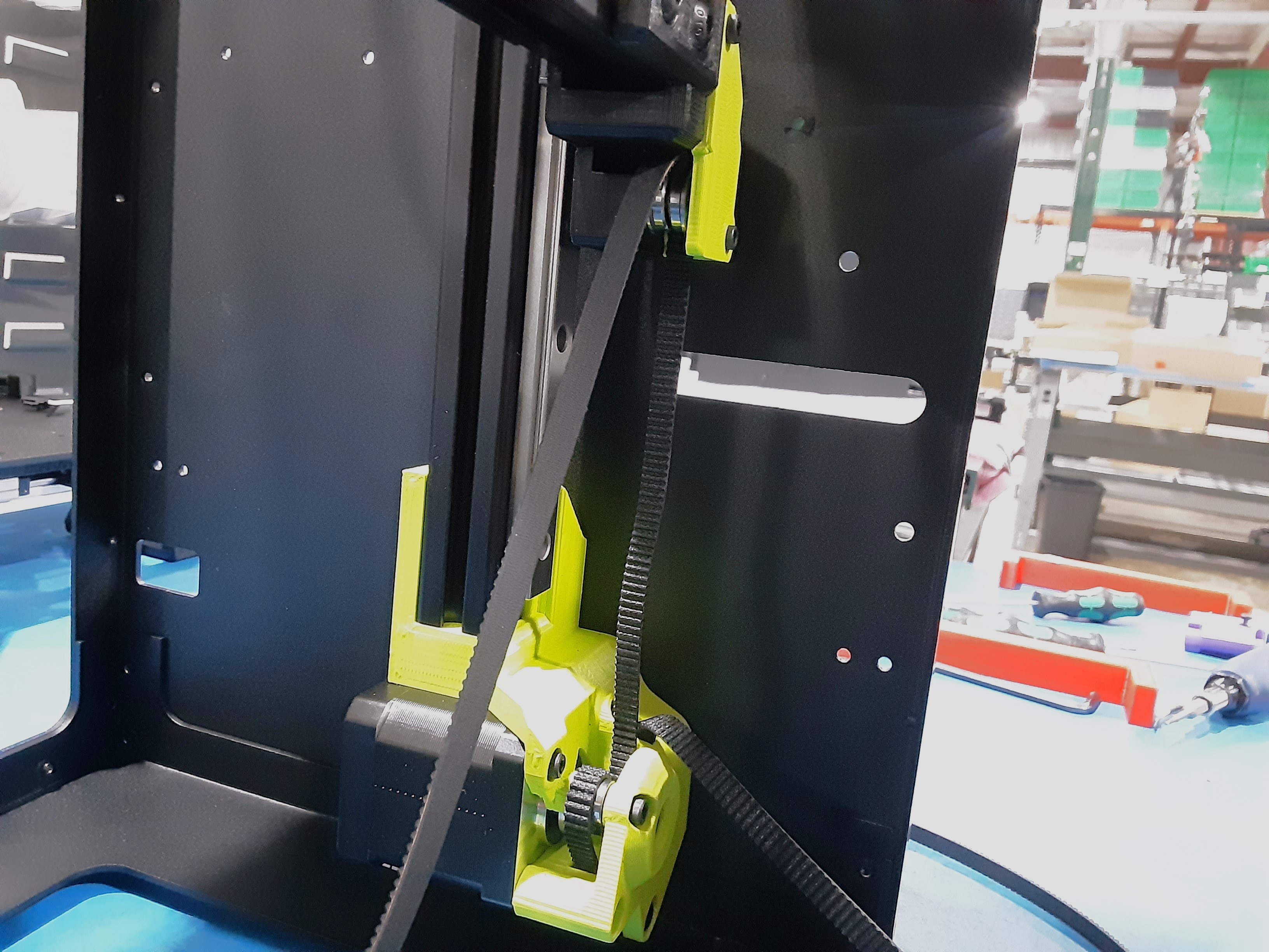
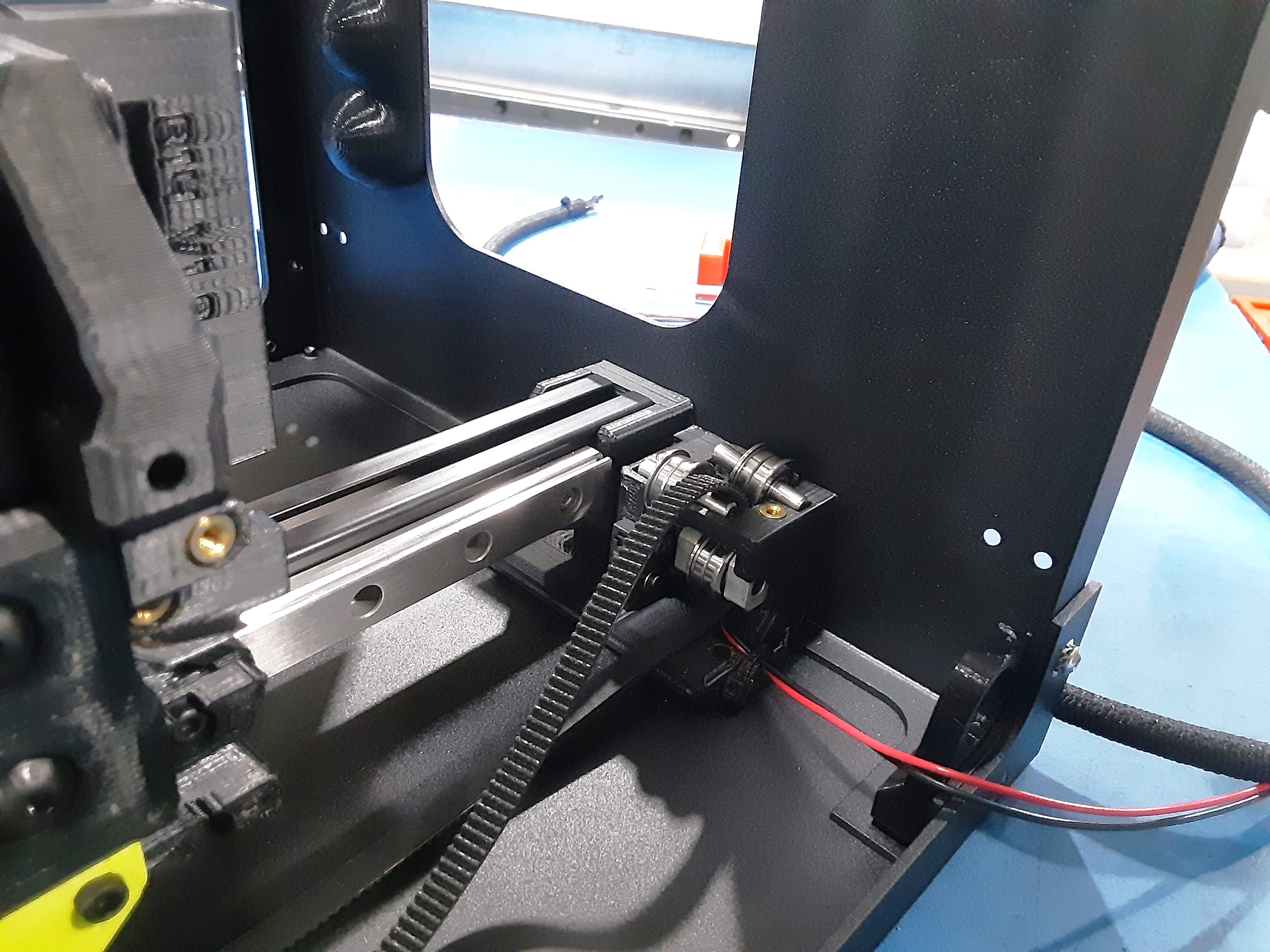
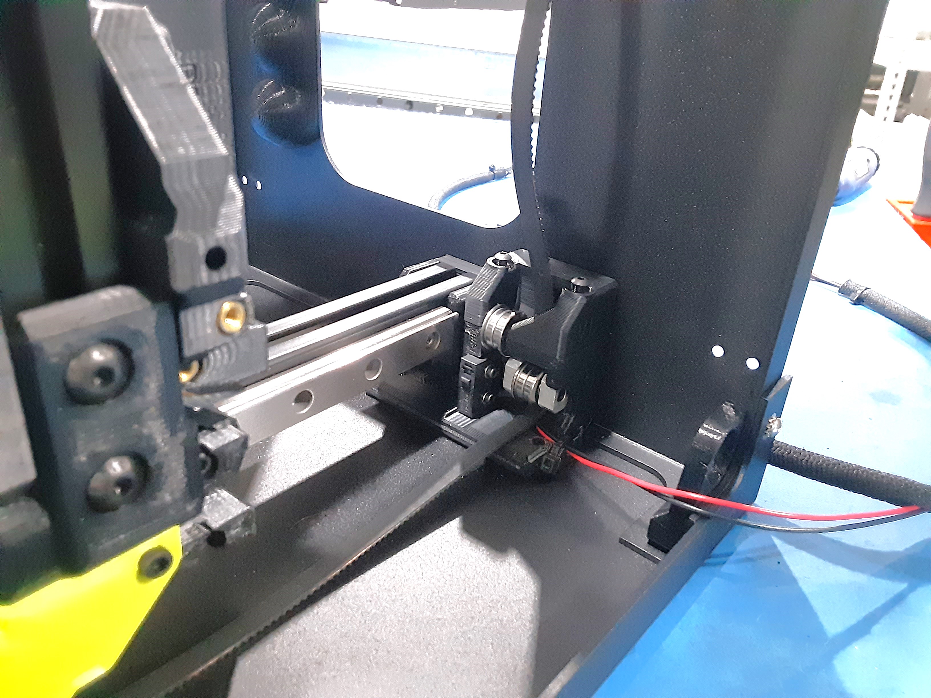
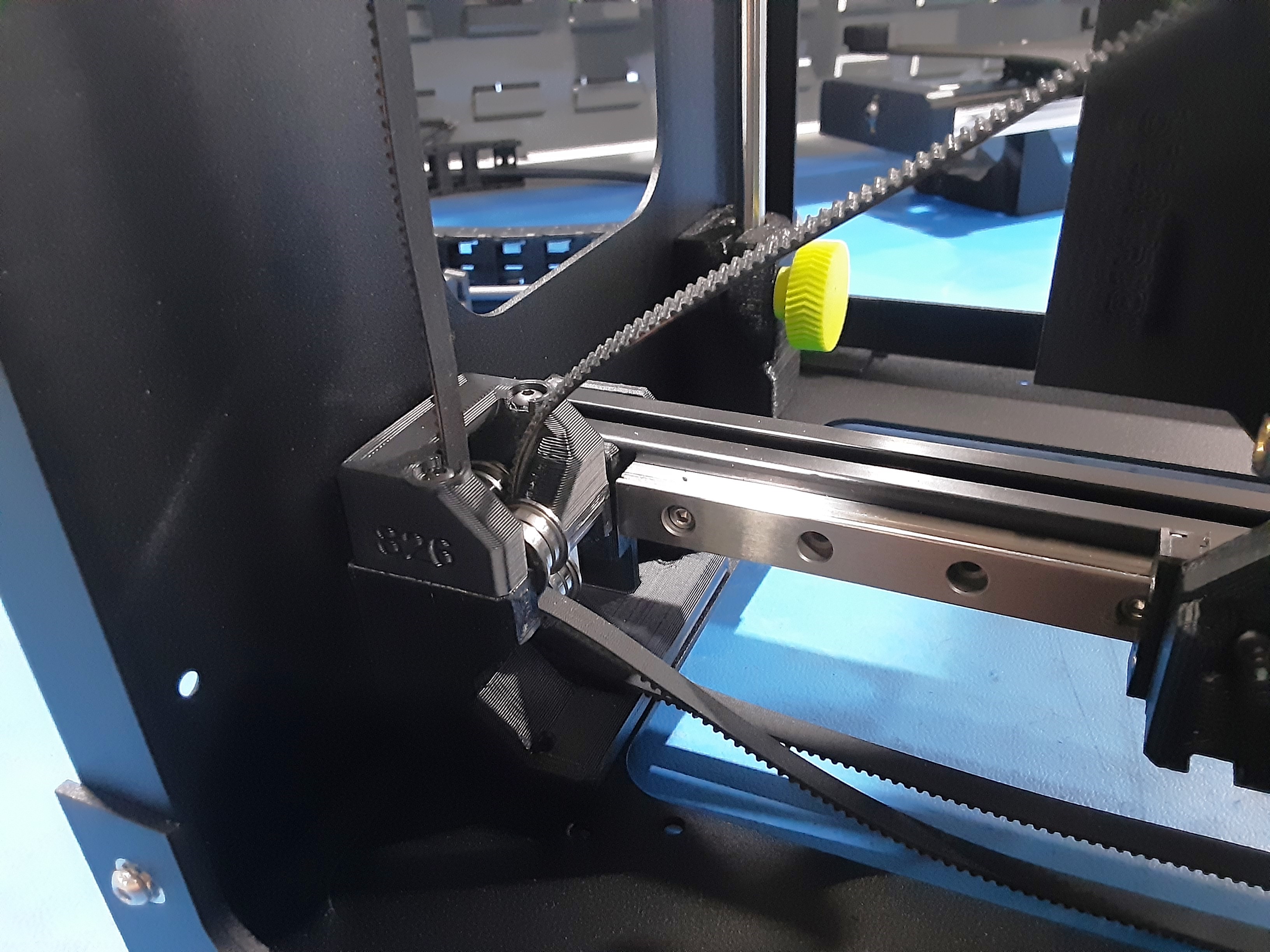
3E) Feed belt from Z.L.L. that did not go to X.C.A. through PP-MP0360 and HD-BU0035s making sure the hex head of HD-BT0301 is facing the back of the F.A.
3F) Continue to feed the belt through PP-GP0827 from Z.L.L. and insert PP-MP0360 into PP-GP0827.
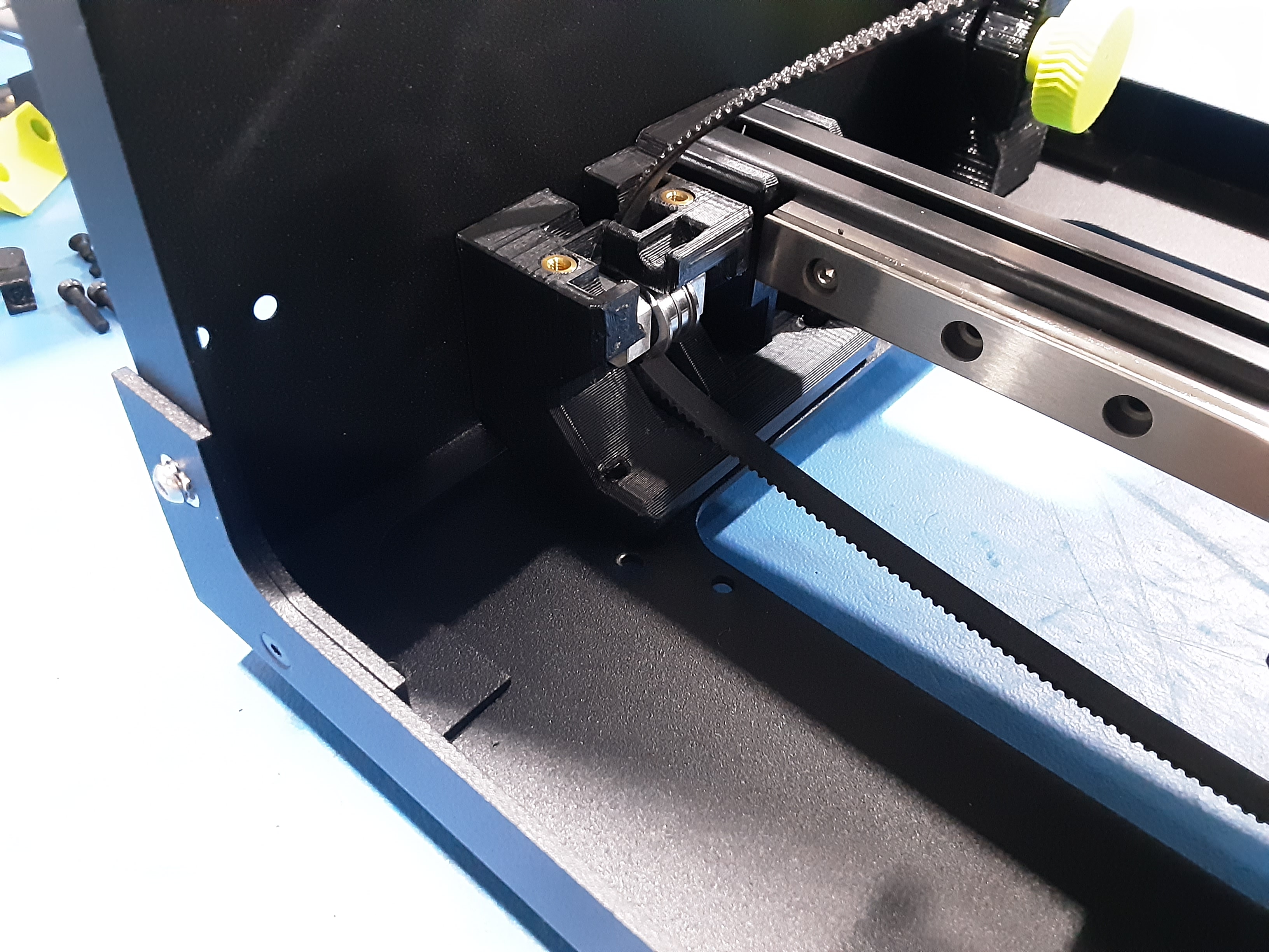
3G) Grab PP-GP0826 x1, HD-RD0093 x2, HD-BU0035 x4, HD-BT0171 x2, and HD-WA0038 x2.
3H) Position the smaller sides of HD-BU0035 x2 together and place them on each HD-RD0093. Place these combos on PP-GP0827 with one going on top of the belt.
3I) Hook PP-GP0826 on the belt and loosely secure it to PP-GP0827 using HD-BT0171 x2 and
HD-WA0038 x2.
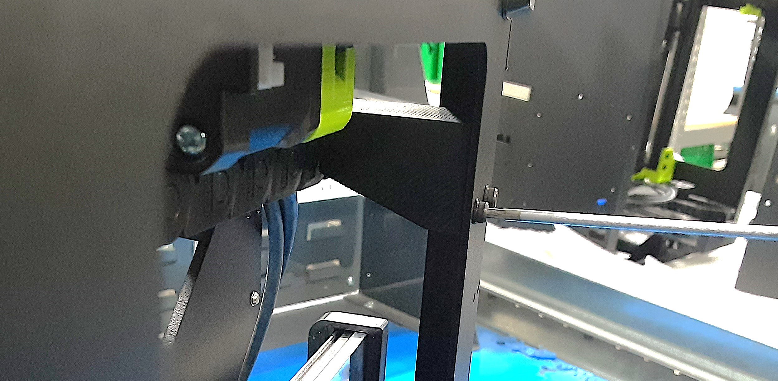
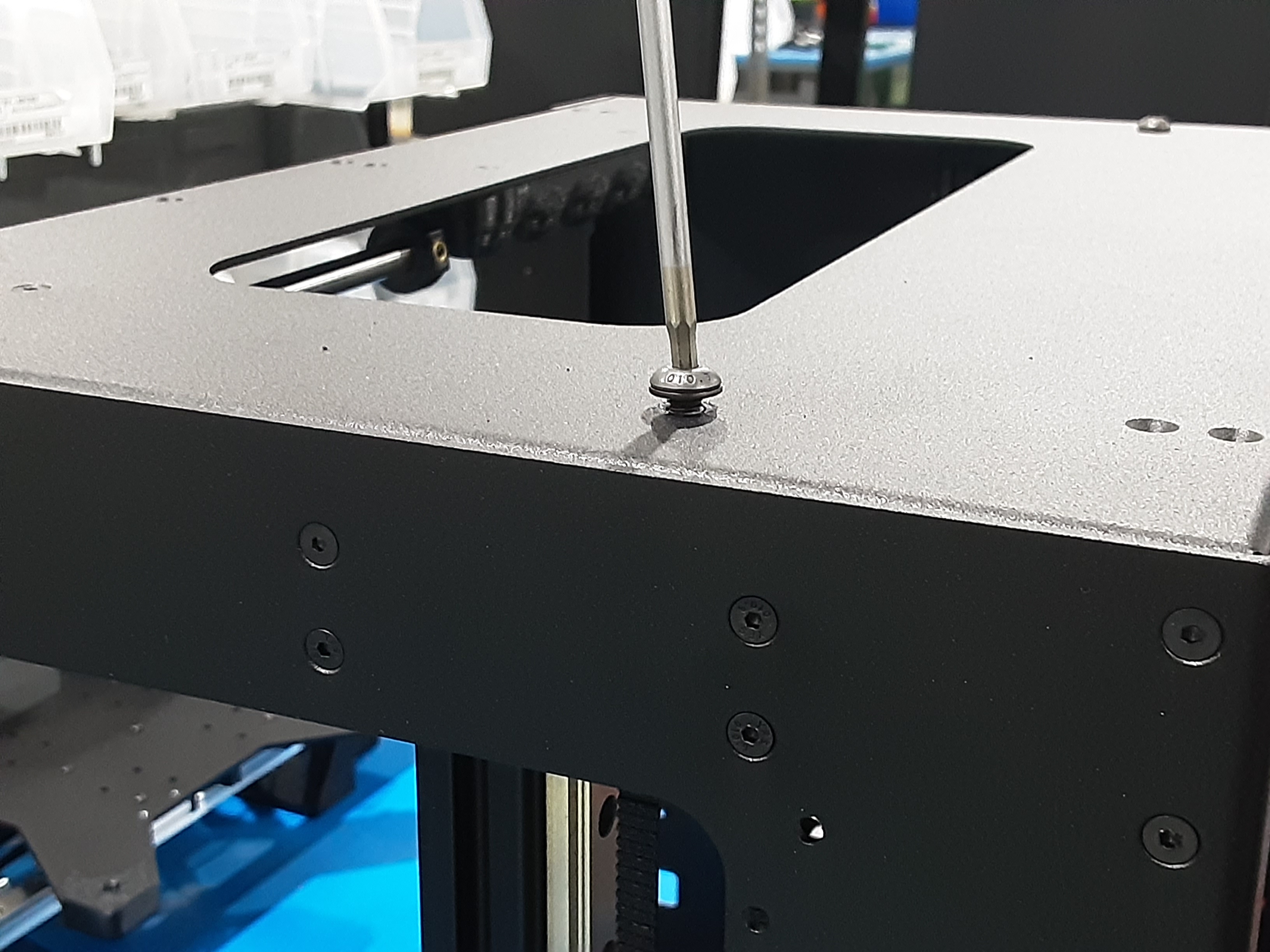
3J) Install HD-BT0158 x1 with HD-WA0040 x1 into PP-MP0360.
3K) Feed belt from Z.L.R. that did not go to X.C.A. through PP-MP0360 and HD-BU0035s making sure the hex head of HD-BT0301 is facing the back of the F.A.
3L) Continue to feed the belt through PP-GP0825 from Z.L.R. and insert PP-MP0360 into PP-GP0825.
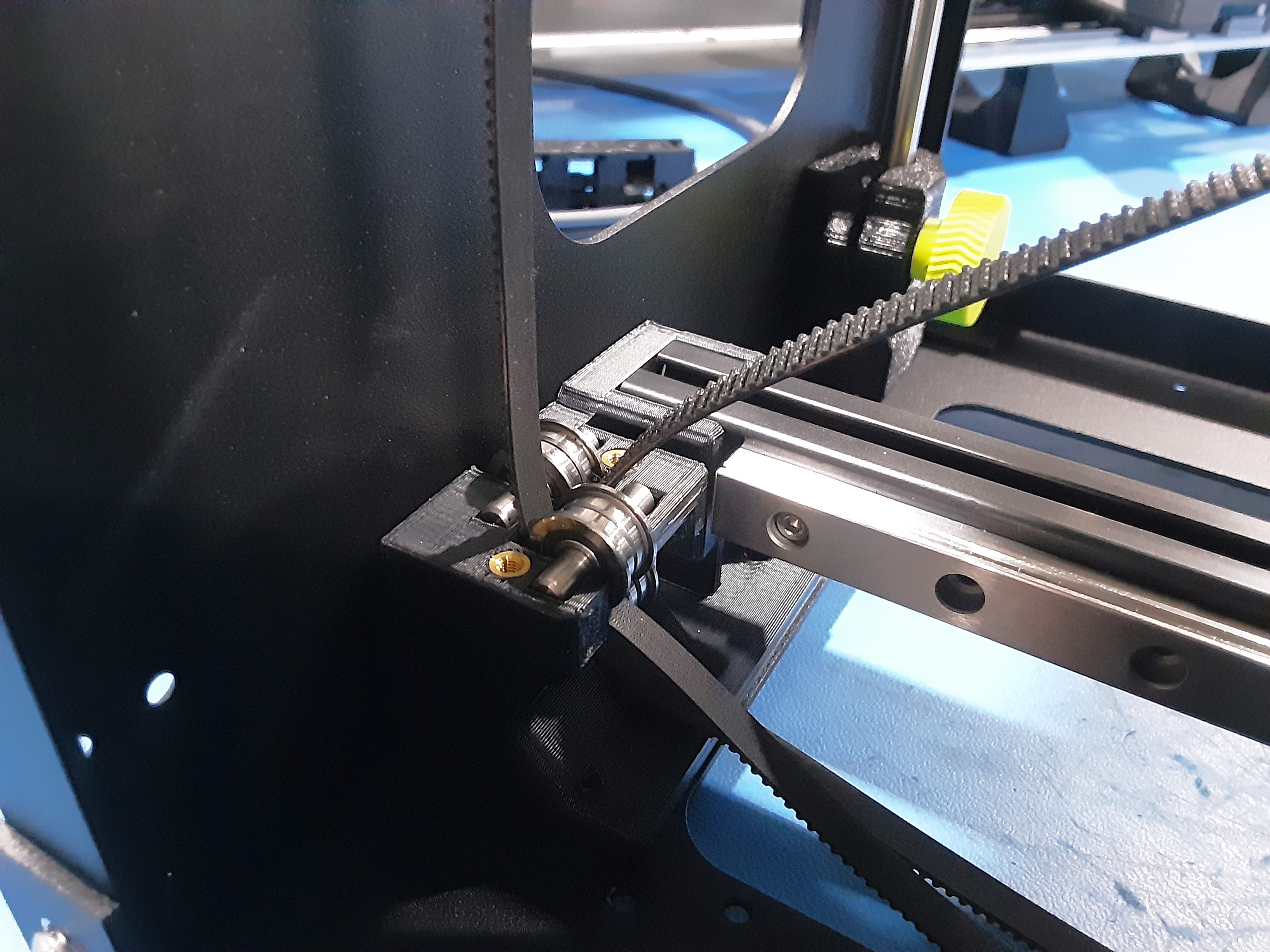
3M) Grab PP-MP0360 x2, HD-BU0035 x4, and HD-BT0301 x2.
3N) Position the smaller sides of HD-BU0035 x2 together and place them on each HD-RD0093. Place one combo on top of the belt coming out of PP-GP0825. Pull the belt coming out of PP-GP0827 from Z.L.L. side and place it in PP-GP0825 with the other bearing combo on top.
3O) Hook PP-GP0826 on the belts and secure it to PP-GP0825 using HD-BT0171 x2 and HD-WA0038 x2.
3P) Install HD-BT0158 x1 with HD-WA0040 x1 into PP-MP0360.
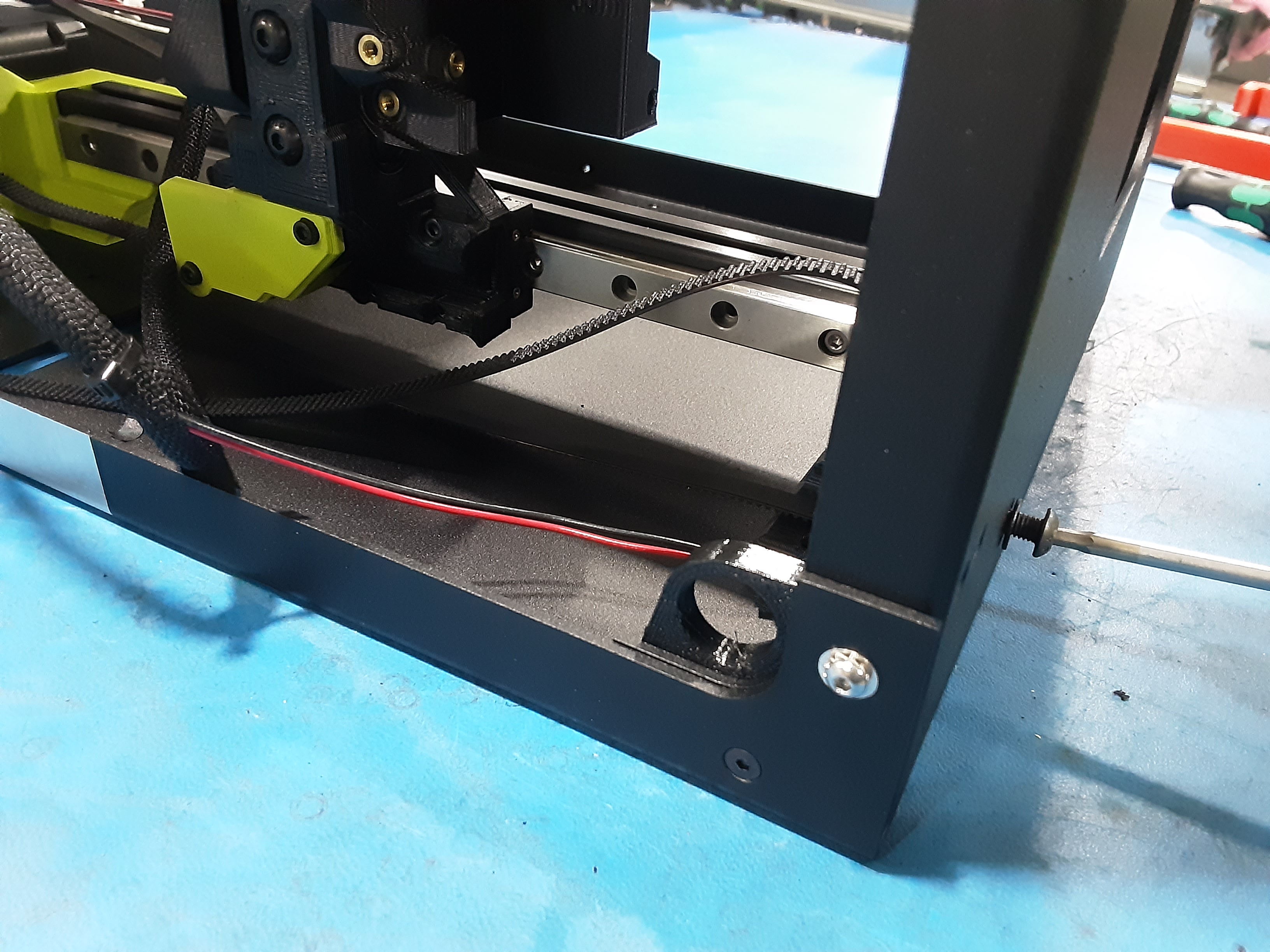
3Q) Pull the Z.L.R. belt coming out of PP-GP0825 and feed it through PP-GP0826 and PP-GP0827 under
HD-BU0035s on the Z.L.L. side. Tighten screws in PP-GP0826 to secure it to PP-GP0827.

X.C. Belting
4A) Feed the belt coming out of PP-GP0827 on the Z.L.L. side from the top, down through PP-GP0812 on the X.C.A. and under the HD-BU0035s.
4B) Feed the belt coming out of PP-GP0825 on the Z.L.R. side from the top, down through PP-GP0813 on the X.C.A. and under the HD-BU0035s.
4C) Make sure the HD-BT0158 bolts on the top holding in the PP-MP0360s are tight and then loosen them three turns.
4D) Remove the two rubber bumpers in Z.L. rods and flip the F.A. to have the top on the table.
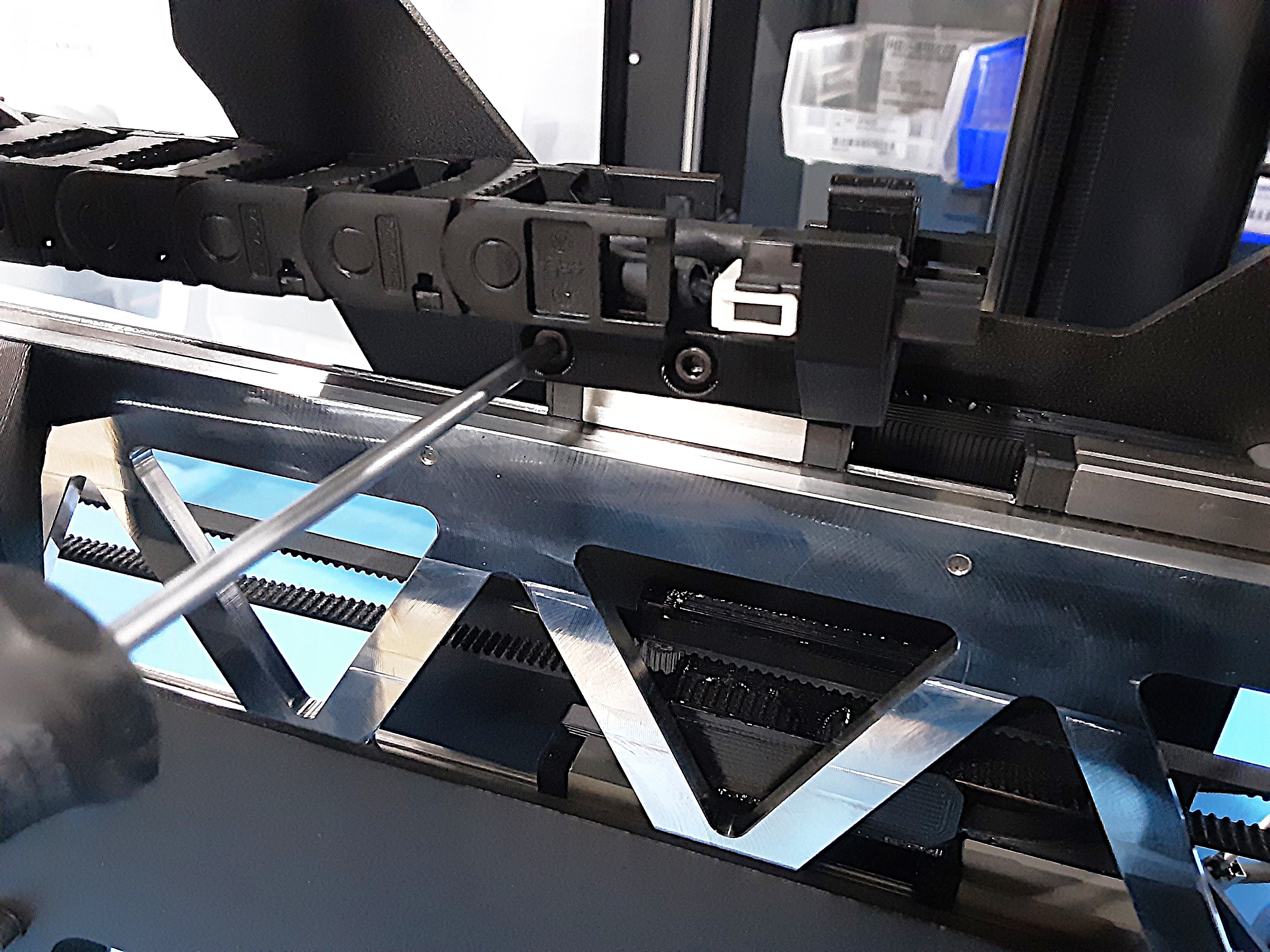
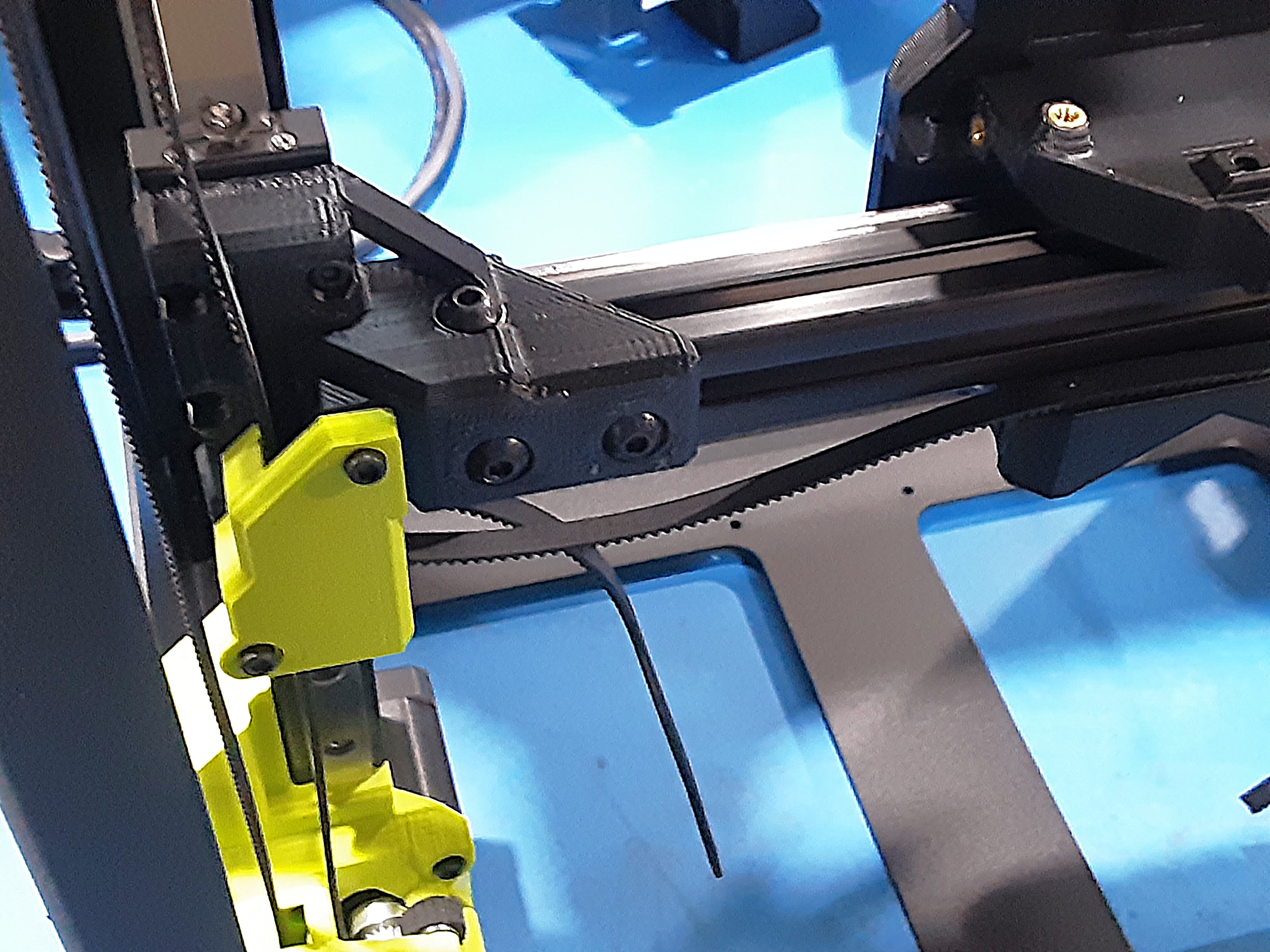
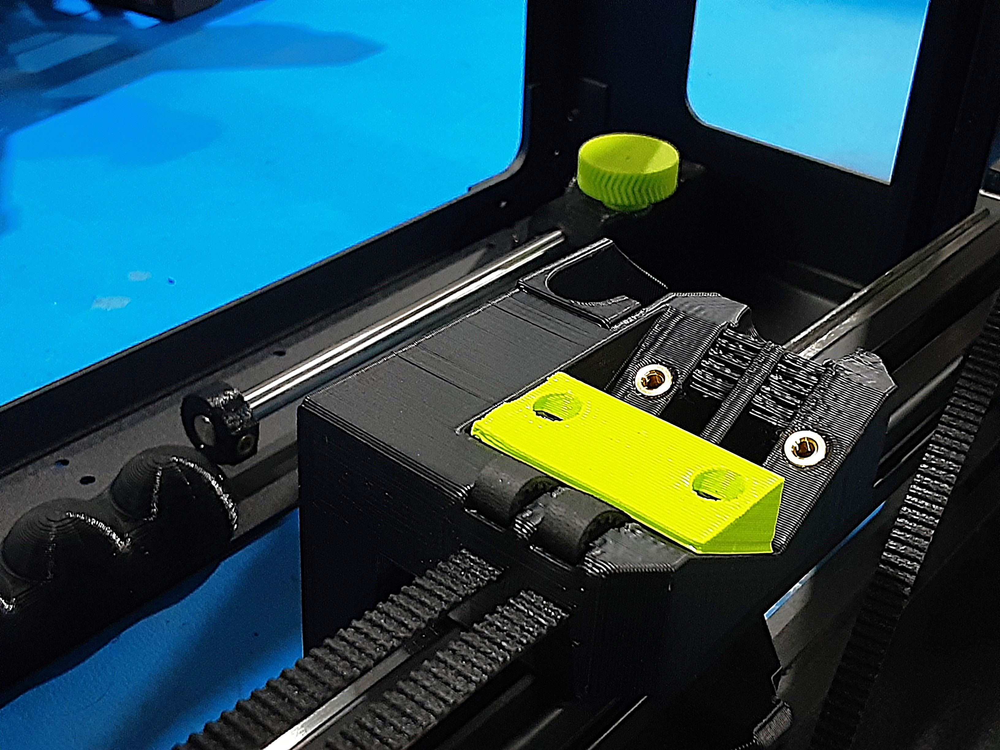
4E) Feed both belts from the X.L.L. side through PP-GP0814 from the X.C.A.
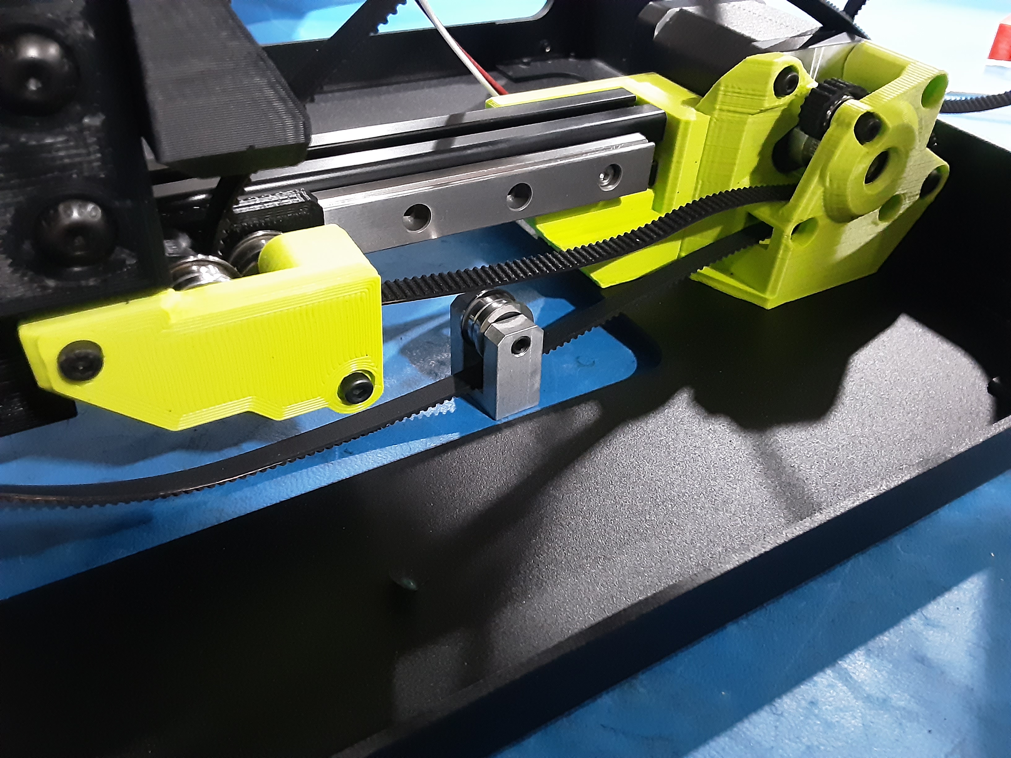
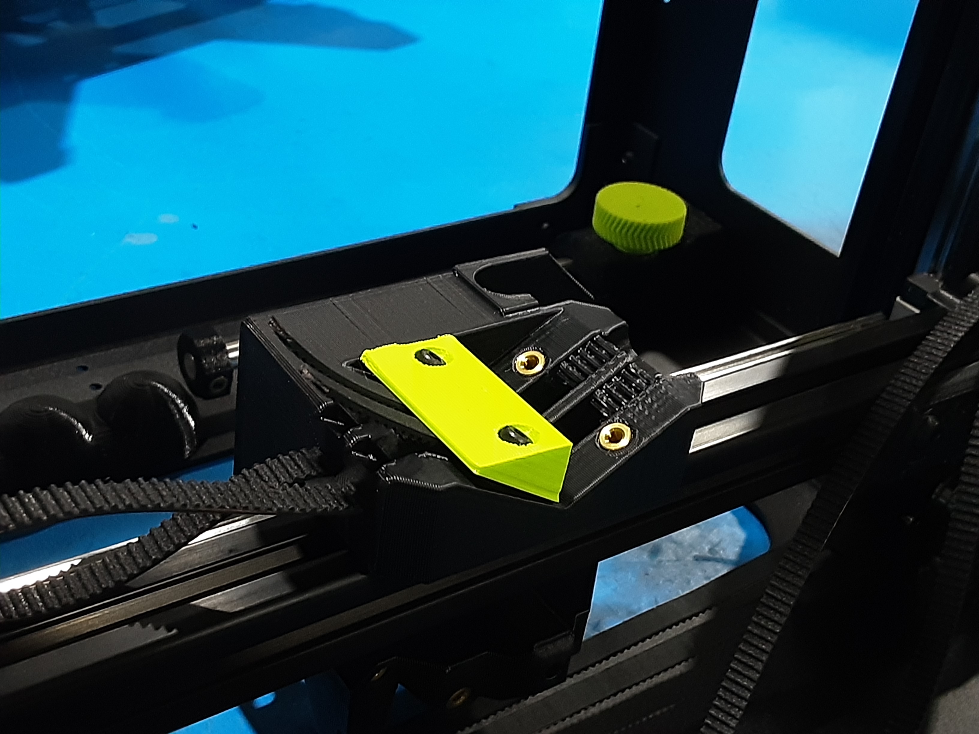
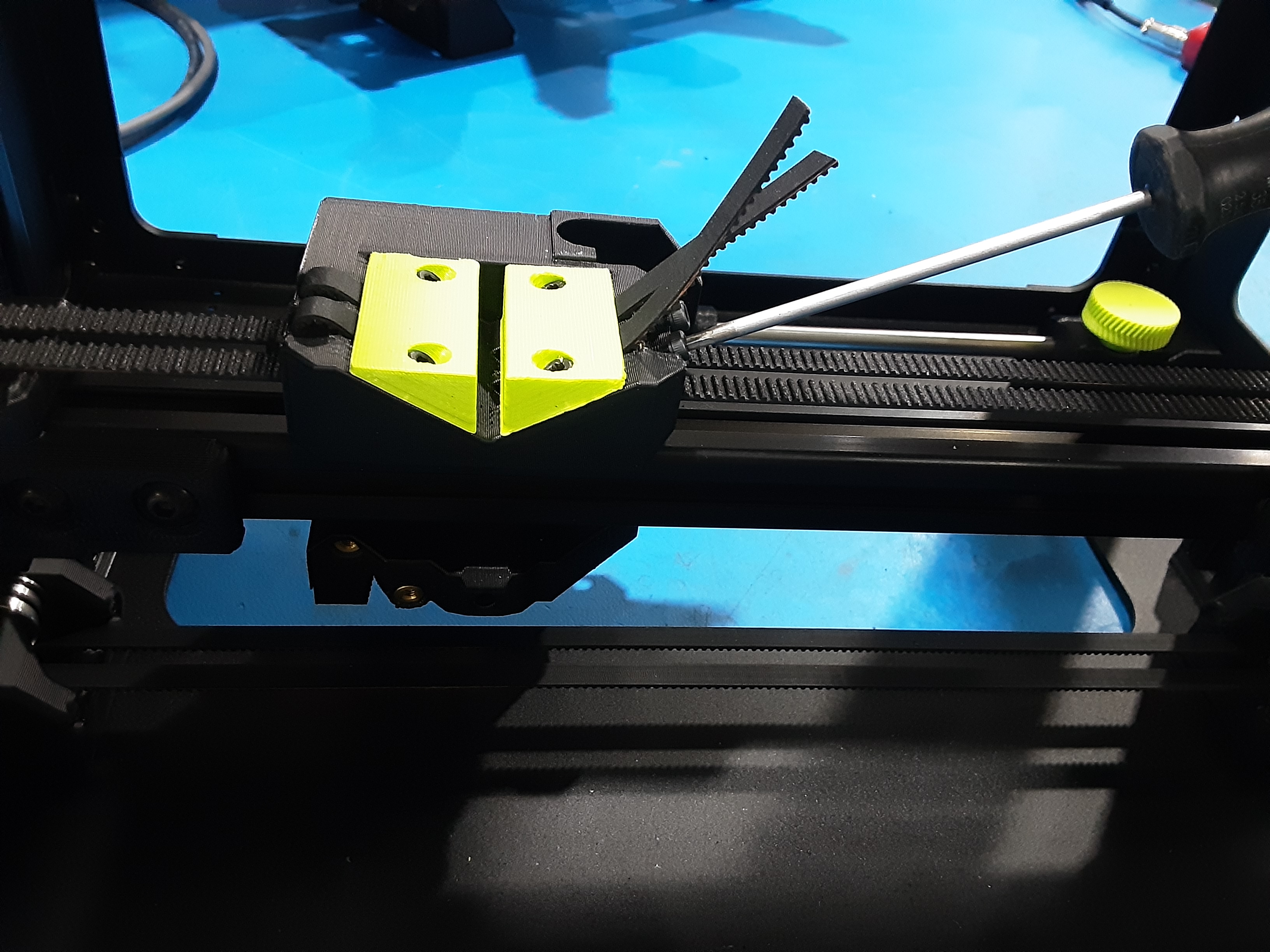
4F) Using HD-BT0157 x2 loosely attach PP-GP0816 to PP-GP0814 over the belts.
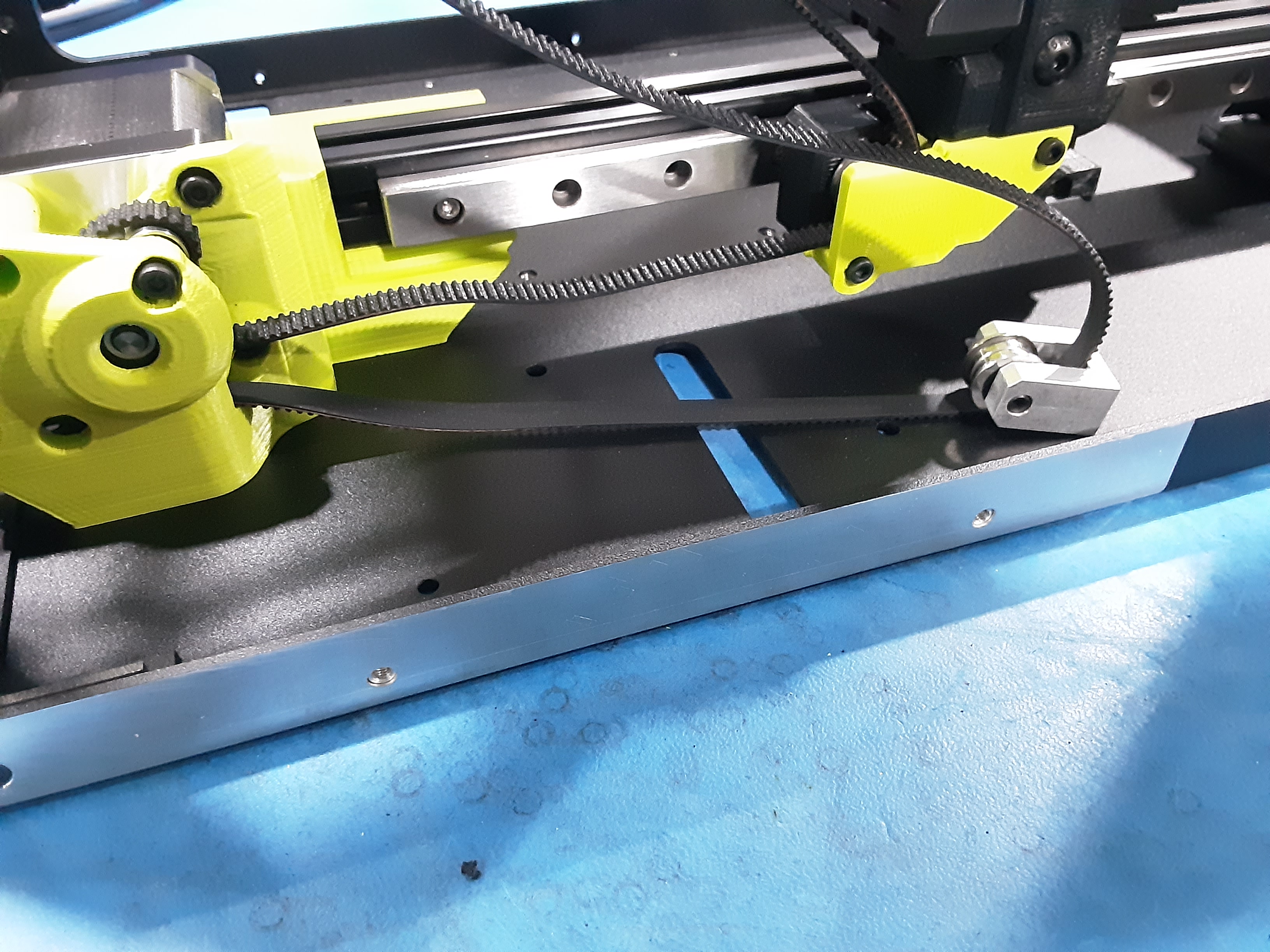
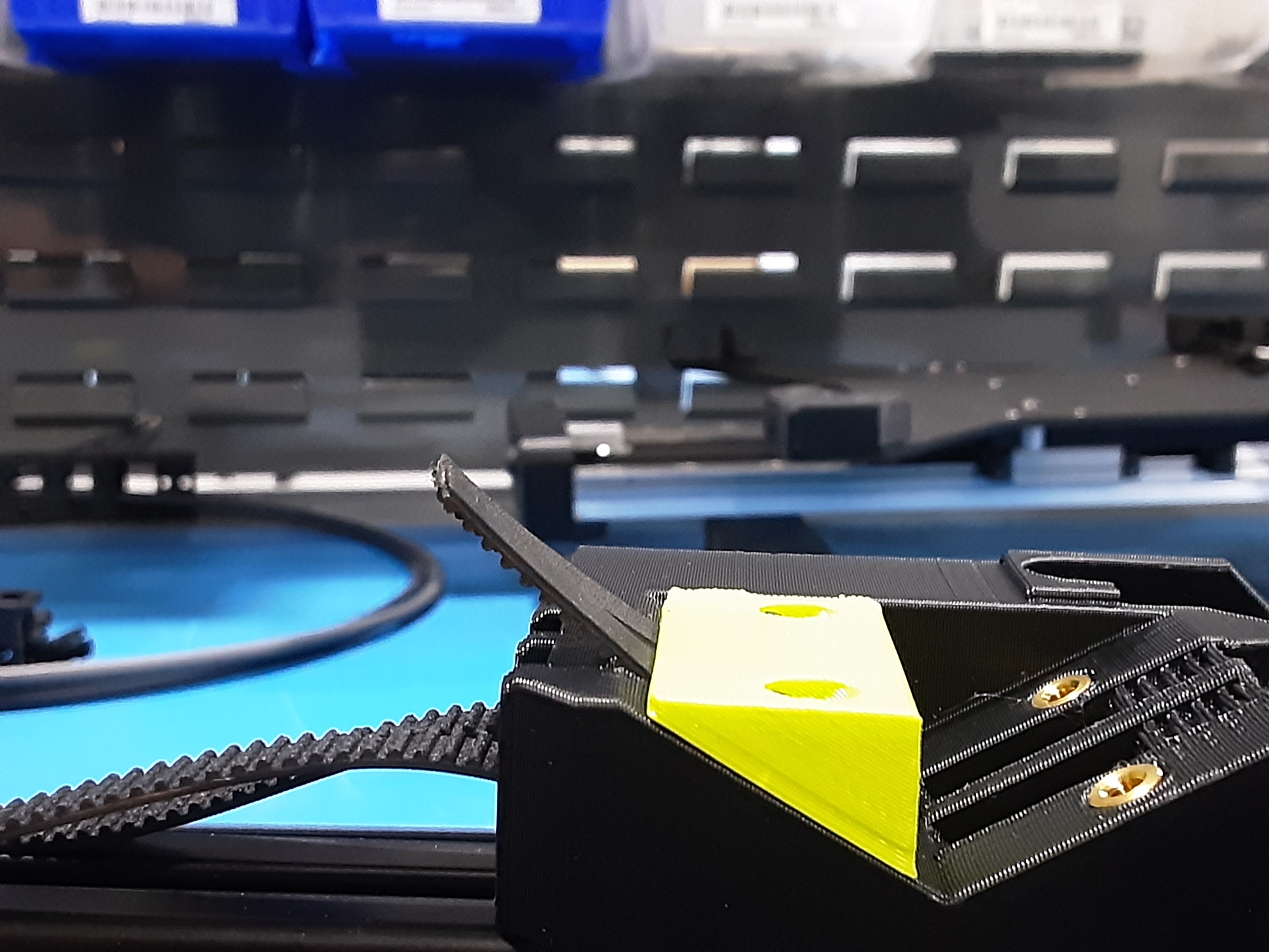
4G) Adjust both belts to be approximately the same length as shown. Then tighten down HD-BT0157s.
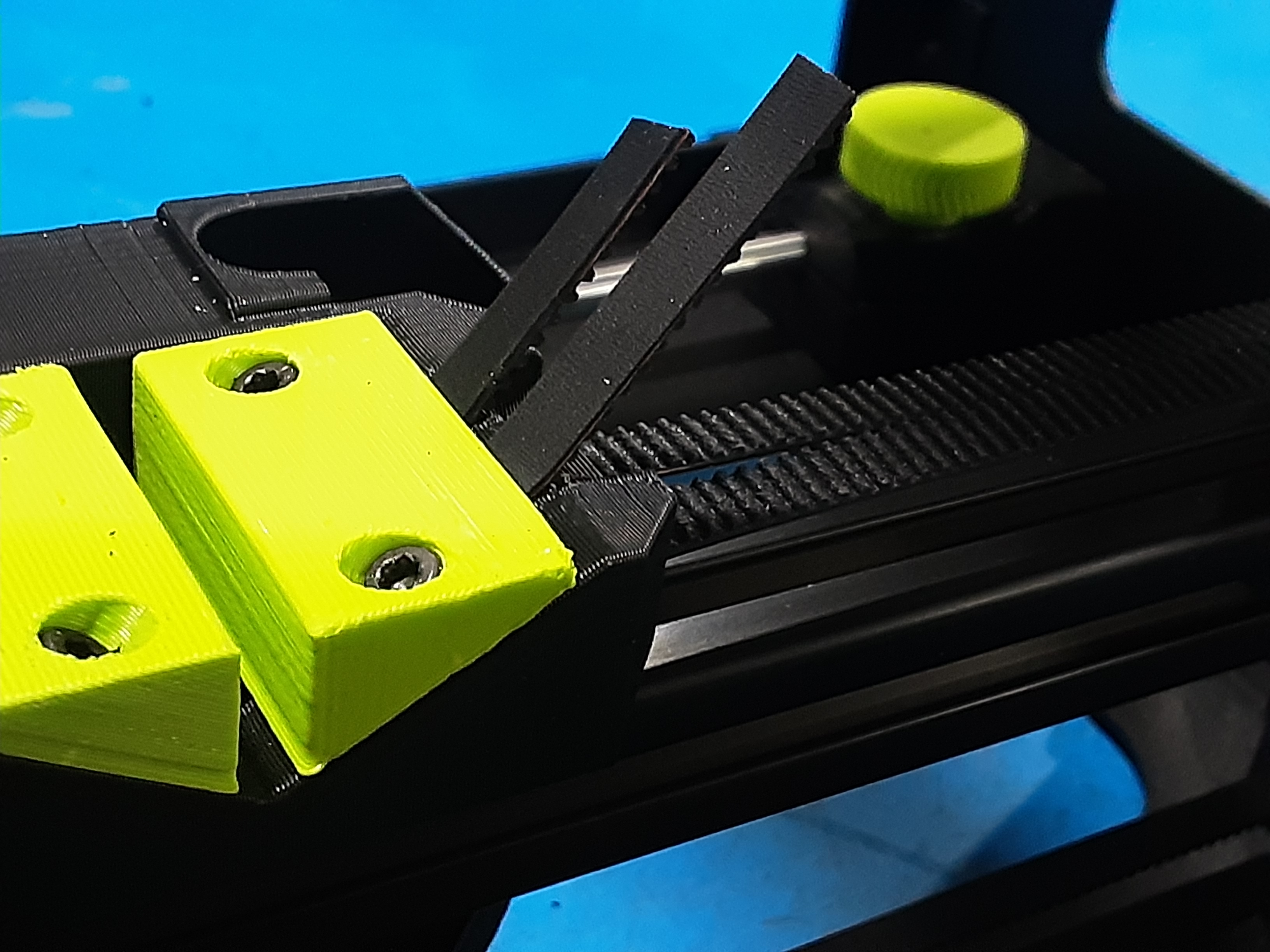
4H) Fold both belts over and tuck them into the slots on PP-GP0814.
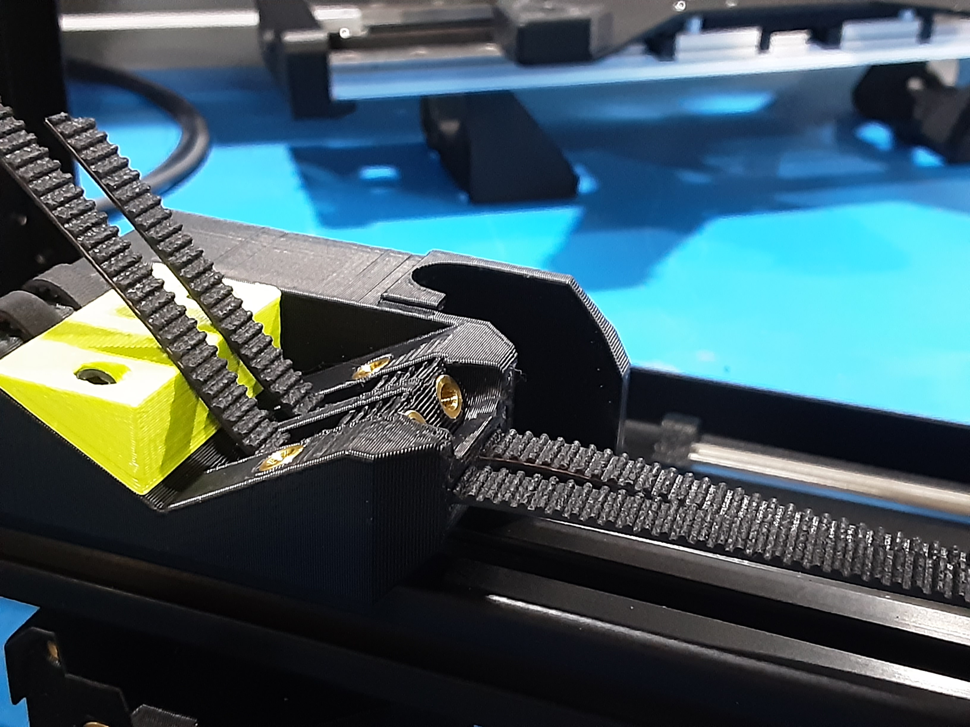
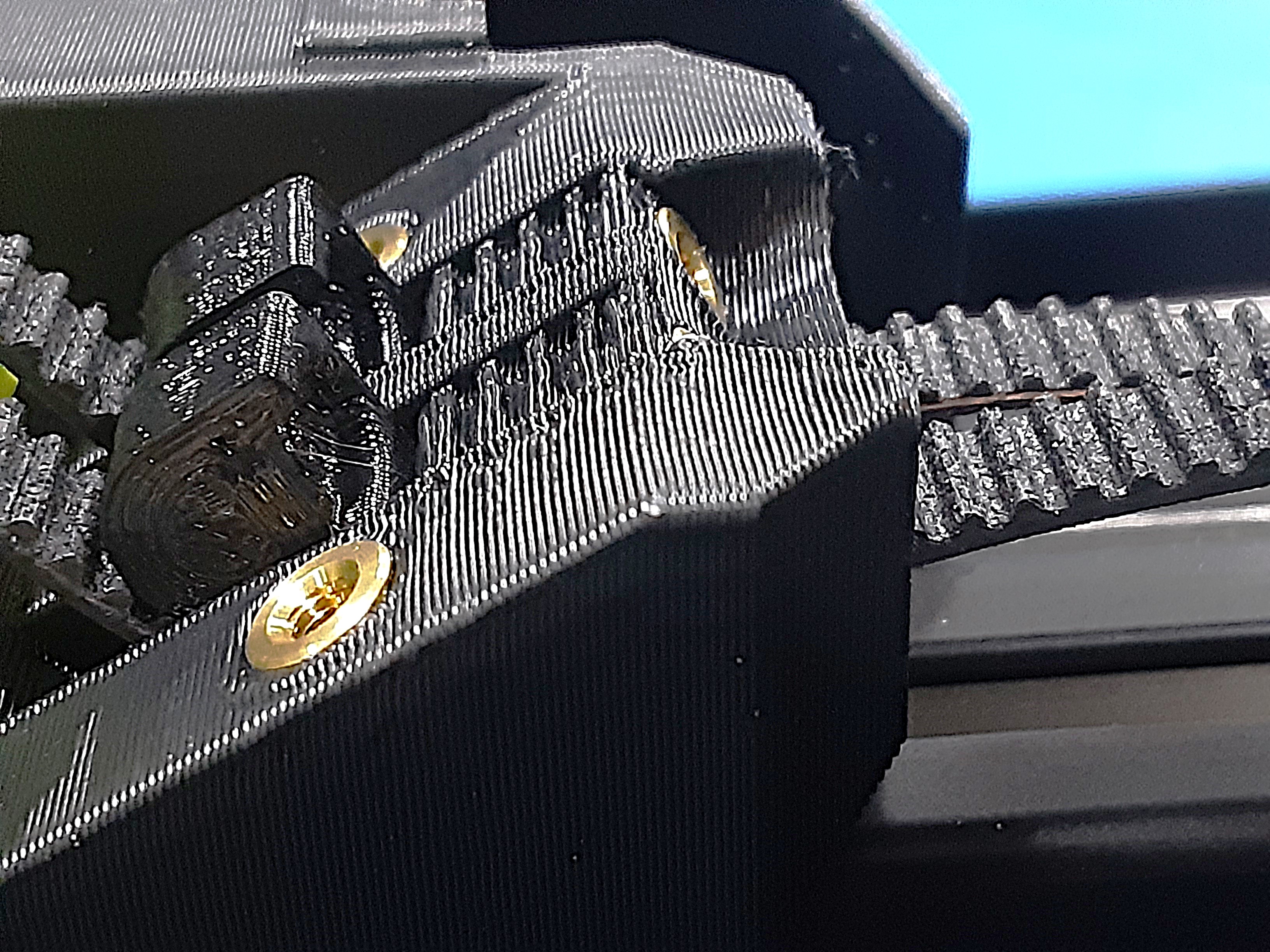
4I) Feed both belts from the X.L.R. side through PP-GP0814.
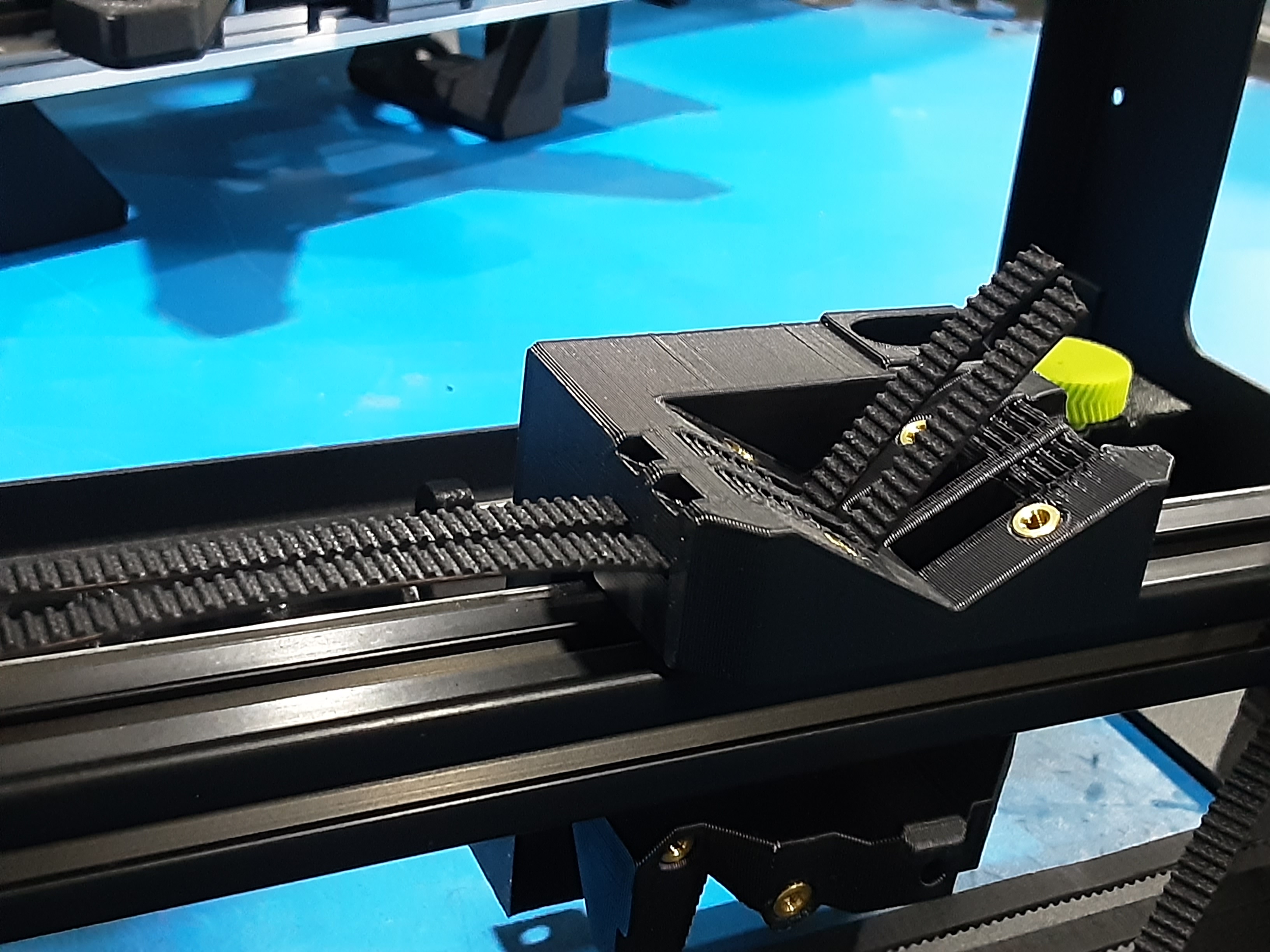
4J) Put PP-GP0899 x2 in the shown orientation on the belts in PP-GP0814.
4K) Using HD-BT0157 x2 loosely attach PP-GP0816 to PP-GP0814 over the belts.
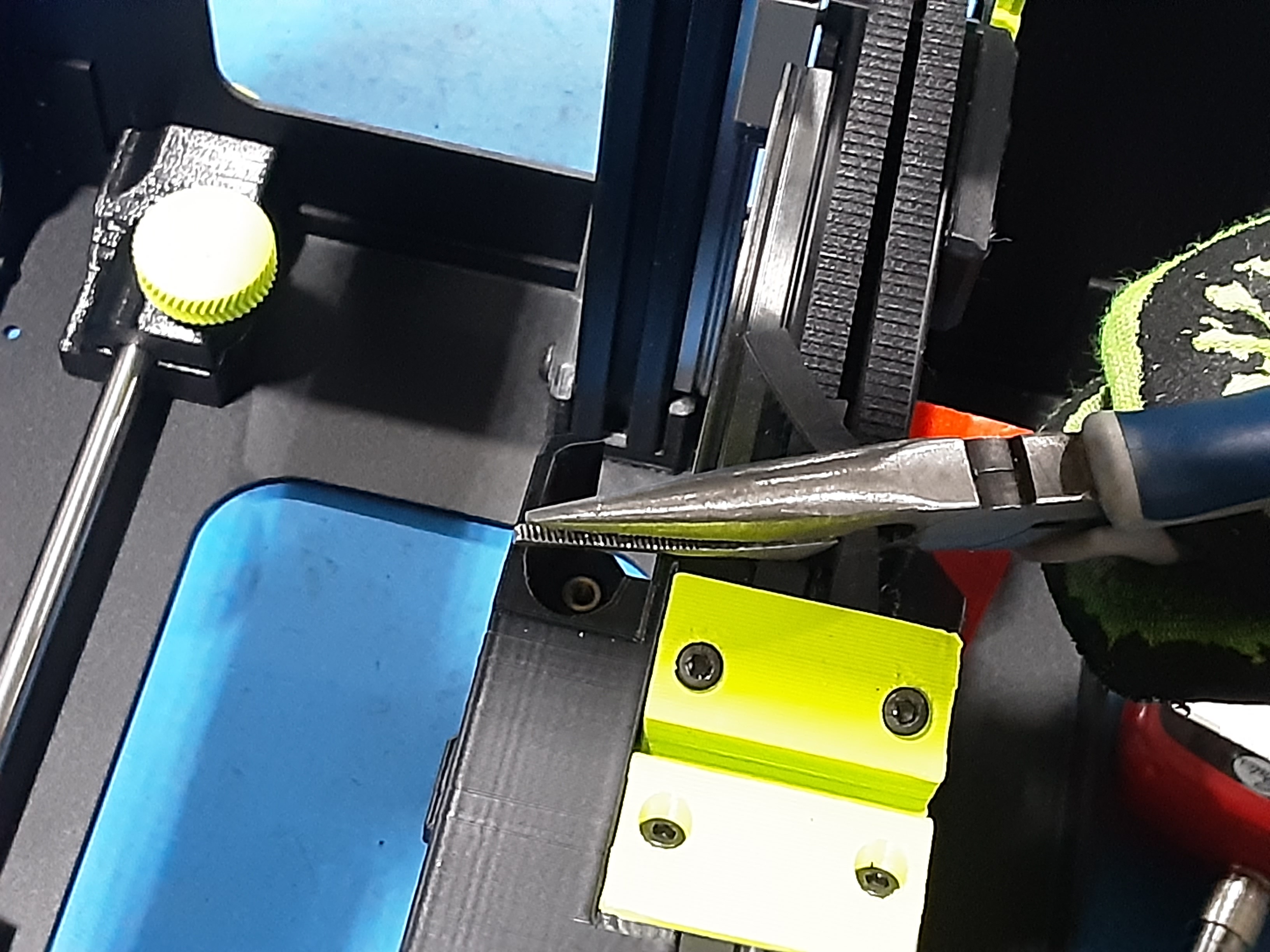
4L) Use pliers to pull both belts tight then tighten down HD-BT0157s. Loosen HD-BT0157 x2 two turns.
Belt Tension
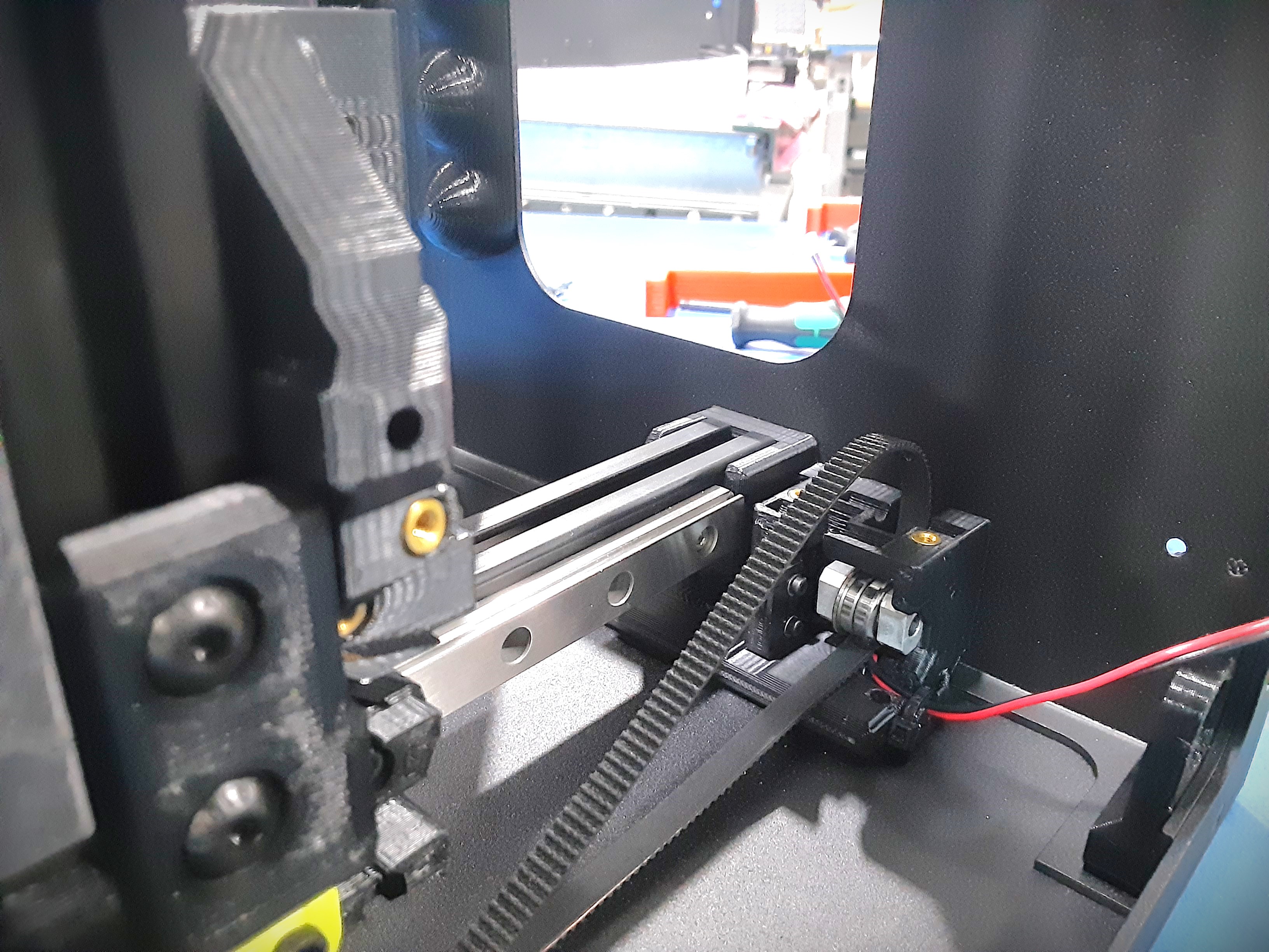
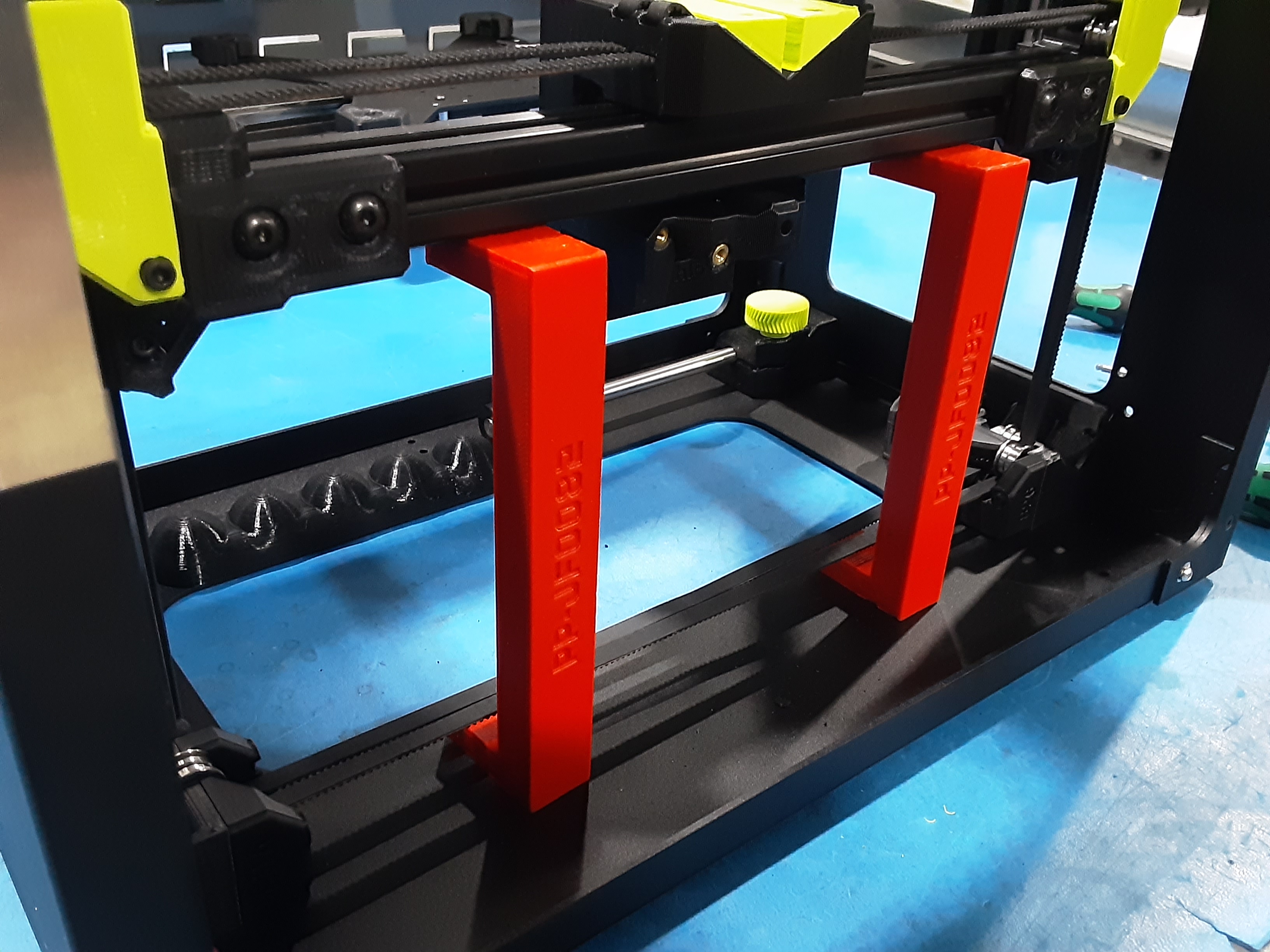
5A) Place two X.C. stand jigs under the X.C.A.
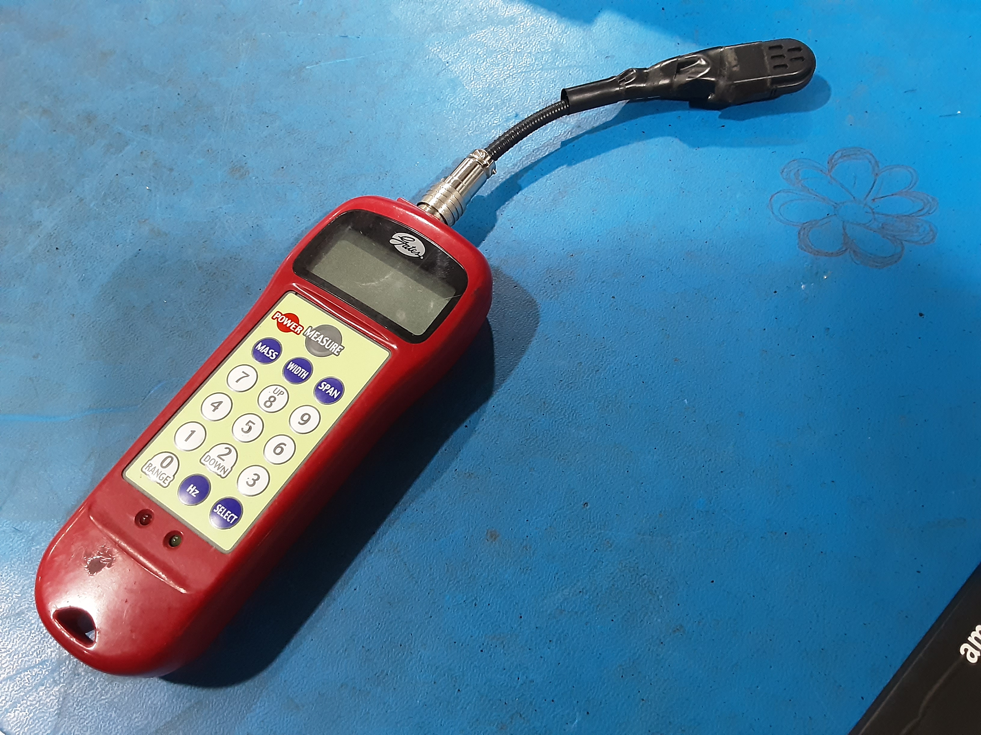
5B) Grab Sonic Tension Meter.
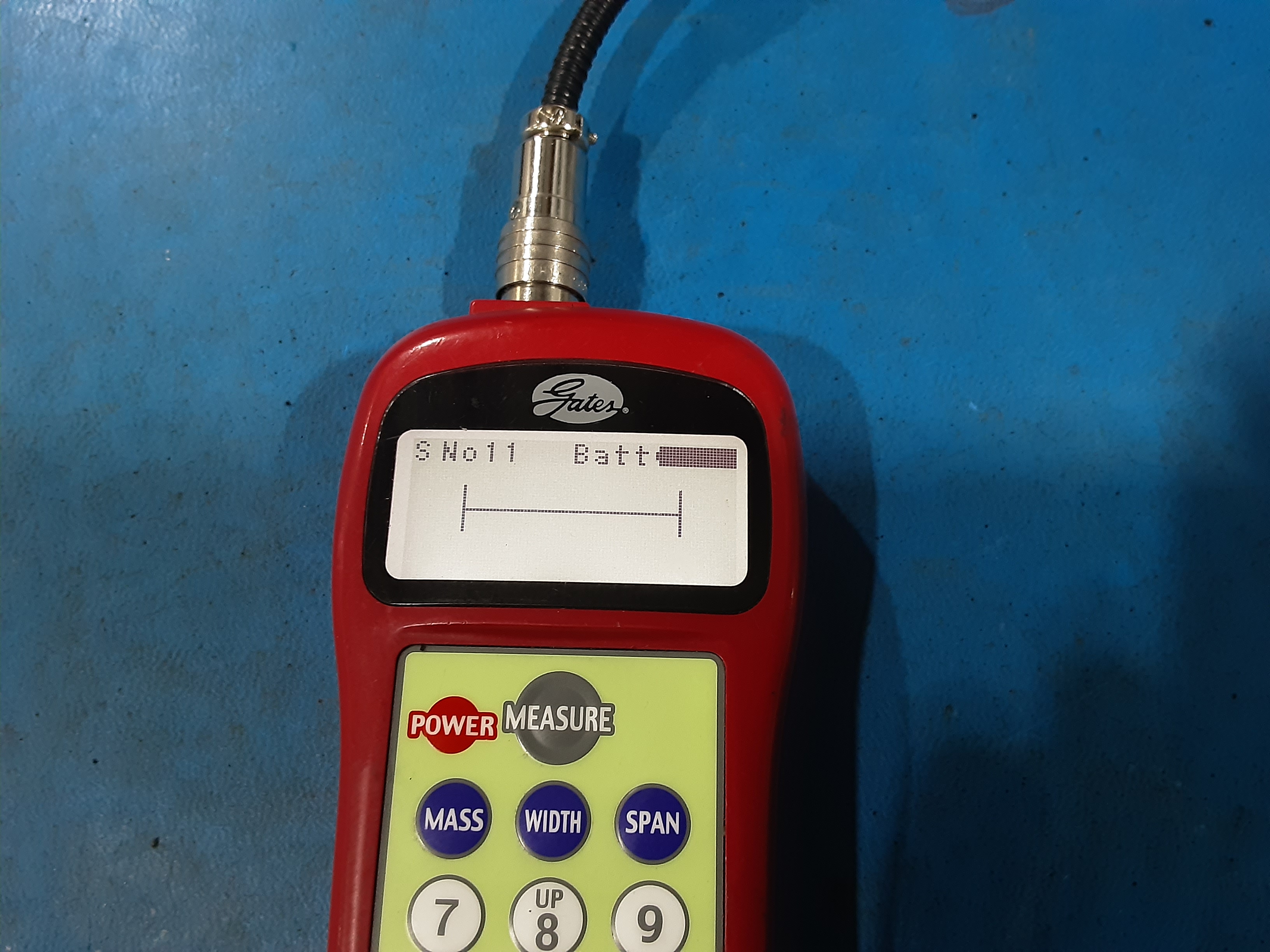
5C) Hit “Power” then “Measure”. Make sure it says “S No11” in the top left corner.
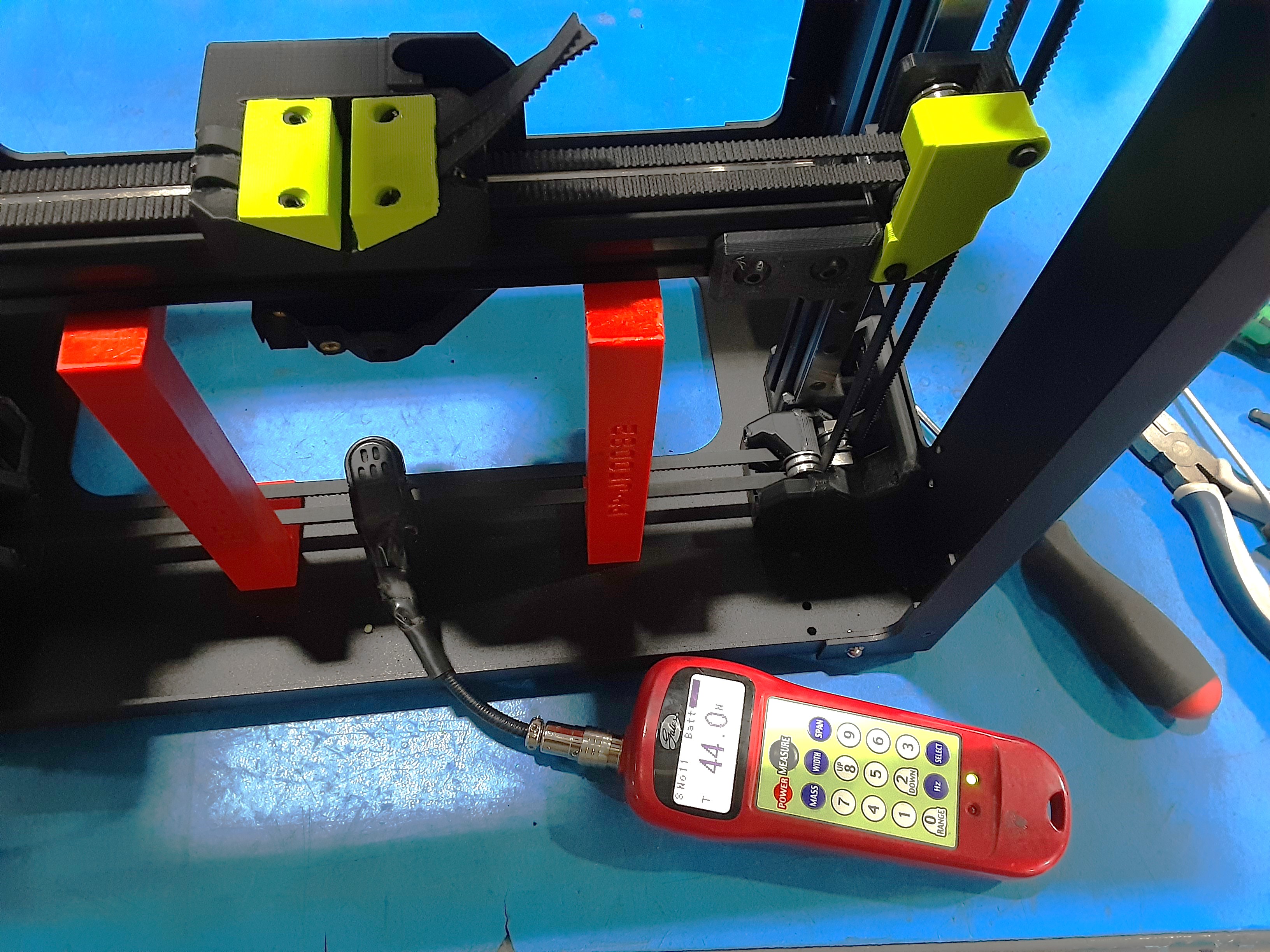
5D) While holding the microphone over the belt, flick the belt to get a measurement on the meter. Sonic Tension Meter should read between 38-44.
5E) Use a pliers to pull the belts tight to get a good measurement if needed. Tighten HD-BT0157 x2 in
PP-GP0816 once a good measurement is reached.
5F) Make sure X.C.A. sits flat on the jigs. May need to loosen and retighten some mounting hardware to achieve this.
5G) Move PP-GP0814 and X.C.A. around.
5H) Double check X.C.A. still sits flat on the jigs and the belts kept their tension.
5I) Install HD-BT0185 x2 in PP-GP0814. Be careful not to overtighten these.
Final Steps
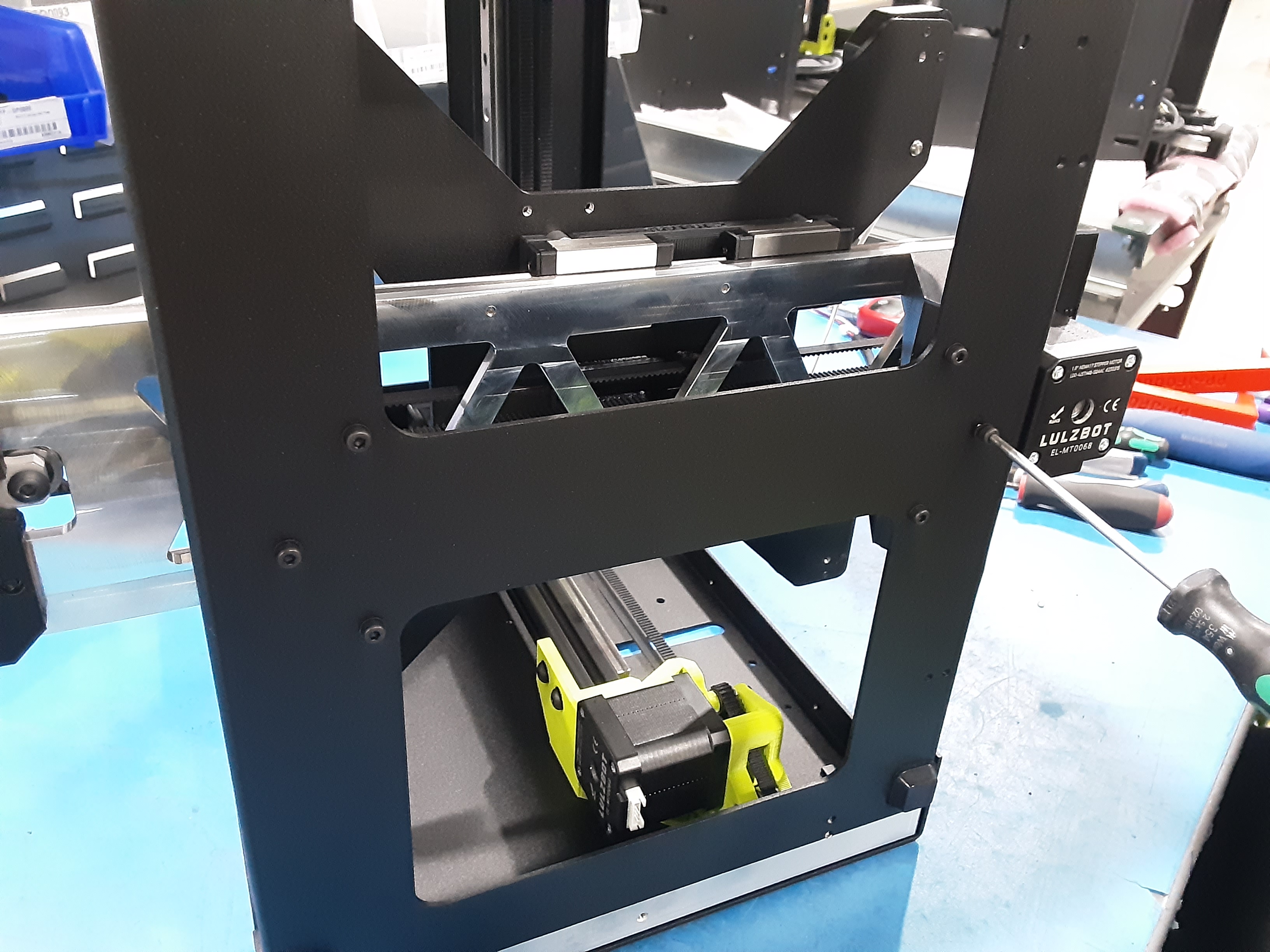
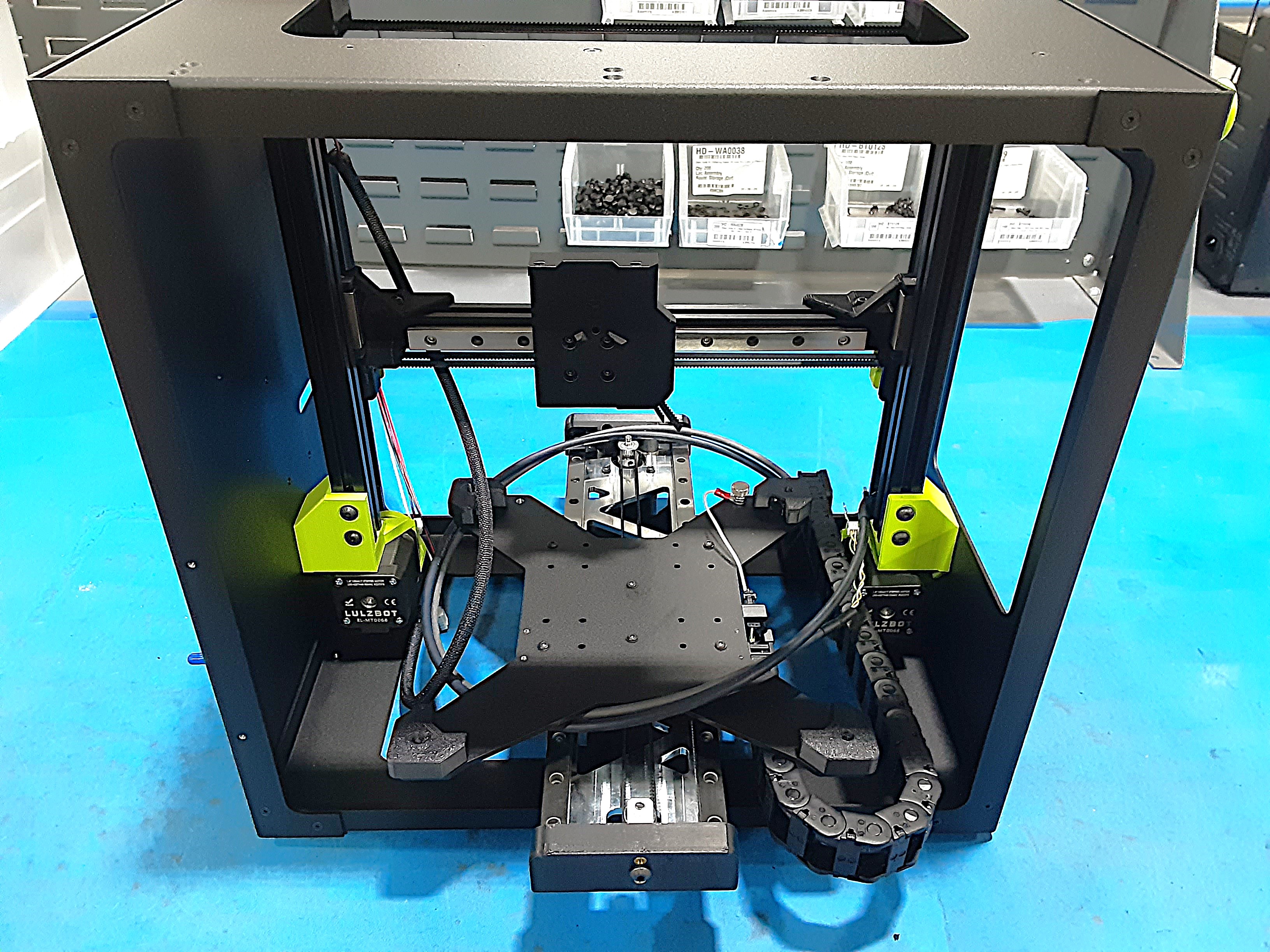
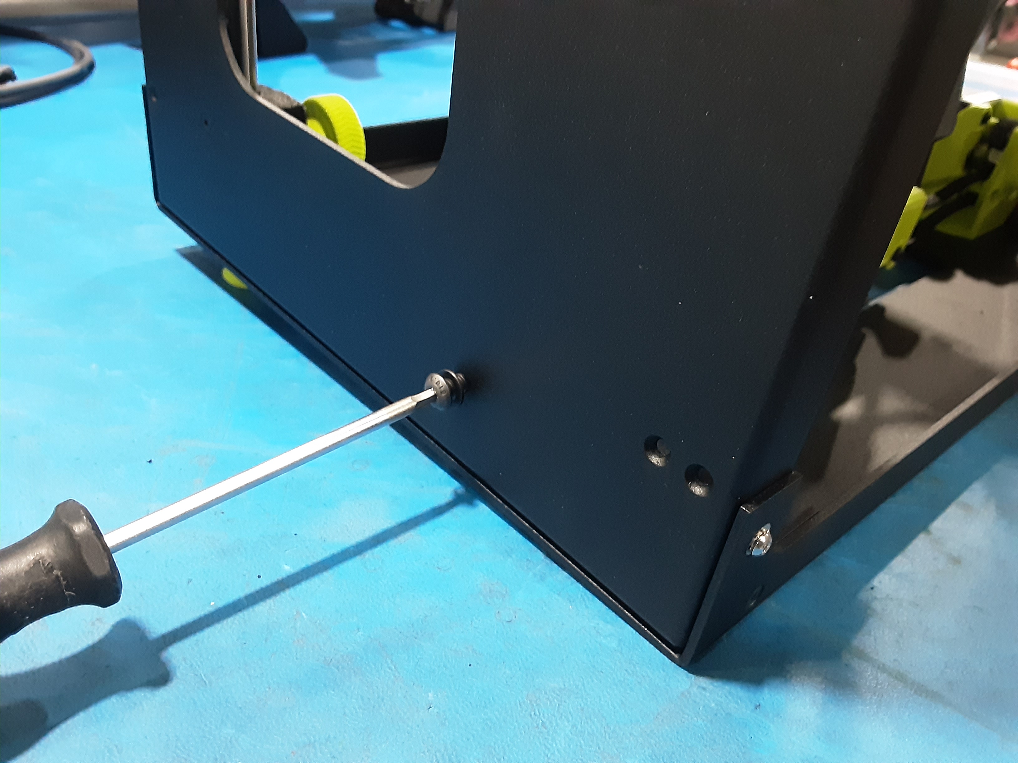
6A) Attach Y.A.B. to the F.A. using HD-BT0157 x6 and HD-WA0038 x6.
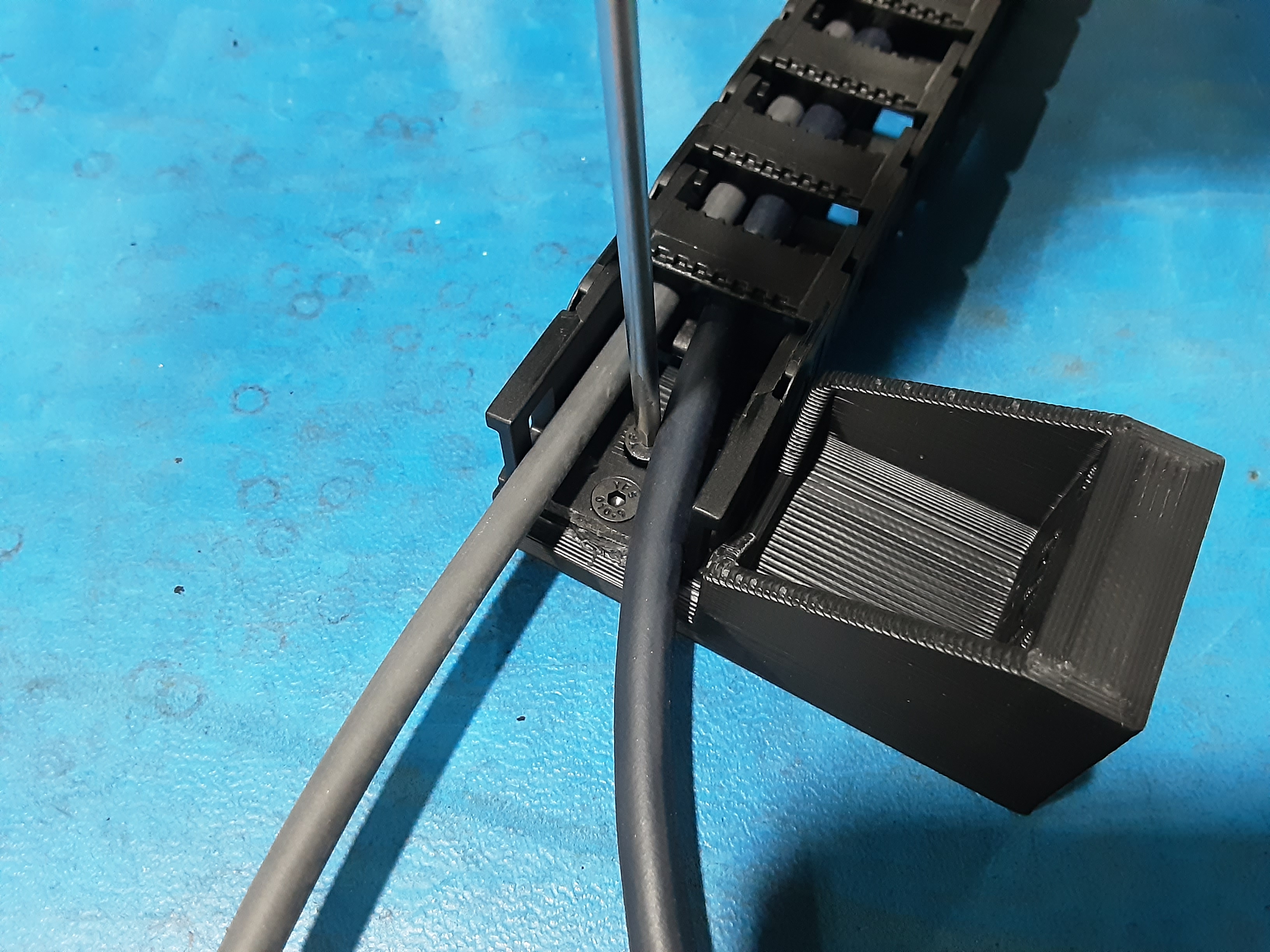
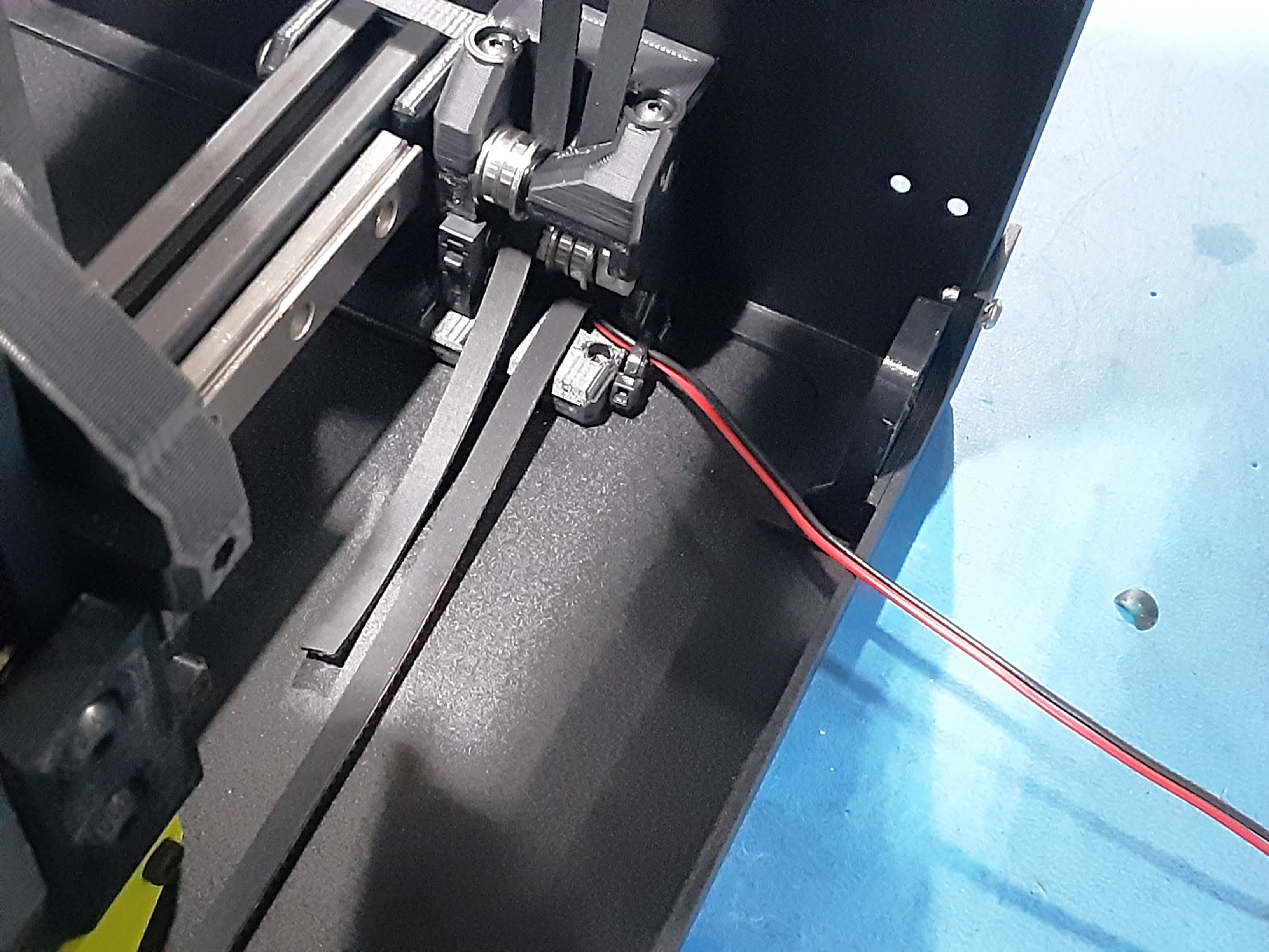
6B) Attach PP-GP0805 to AS-CB0218 chain on the bed connectors side using HD-BT0128 x2.
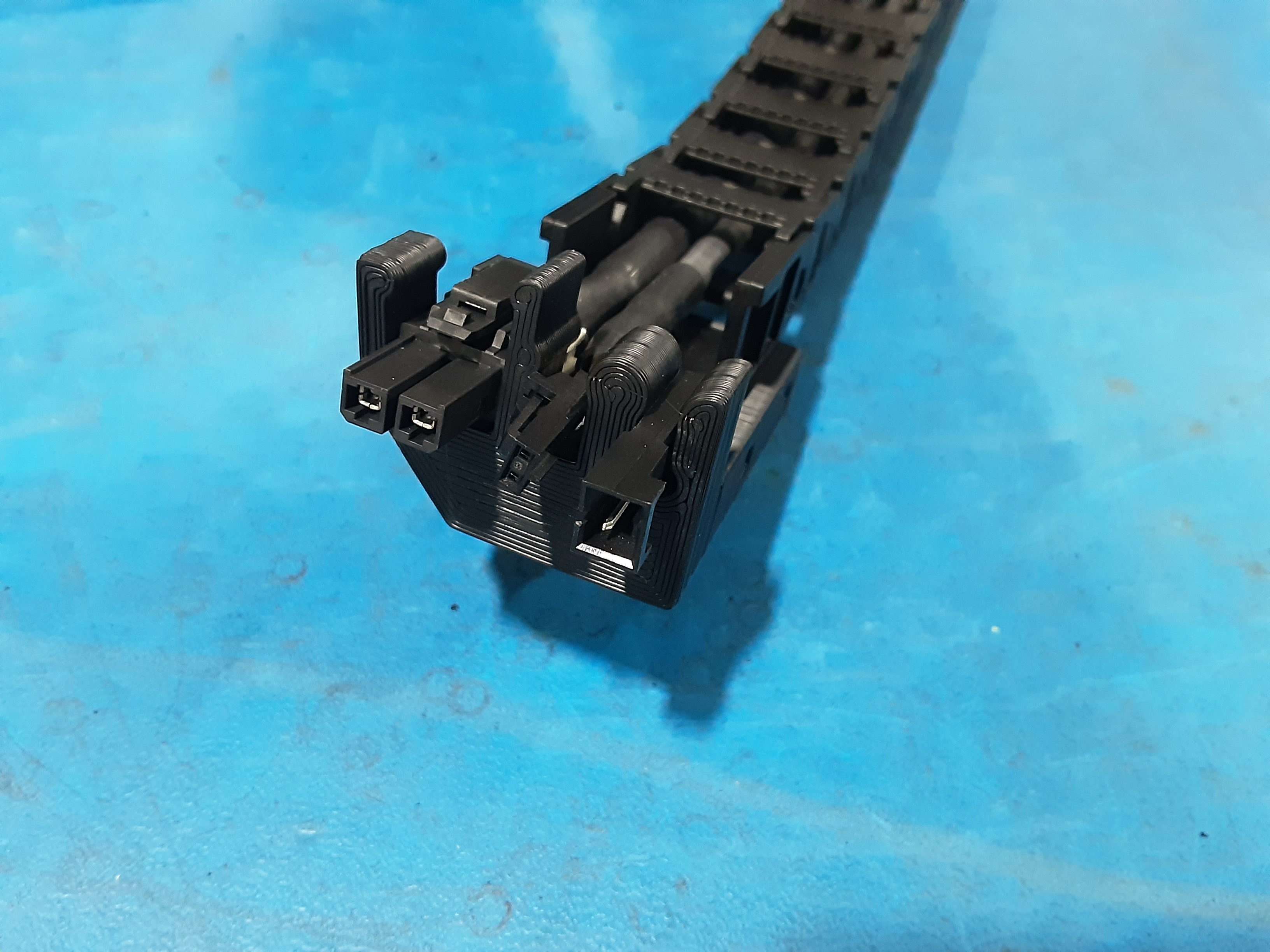
6C) Put the bed connectors from AS-CB0218 into PP-GP0805.
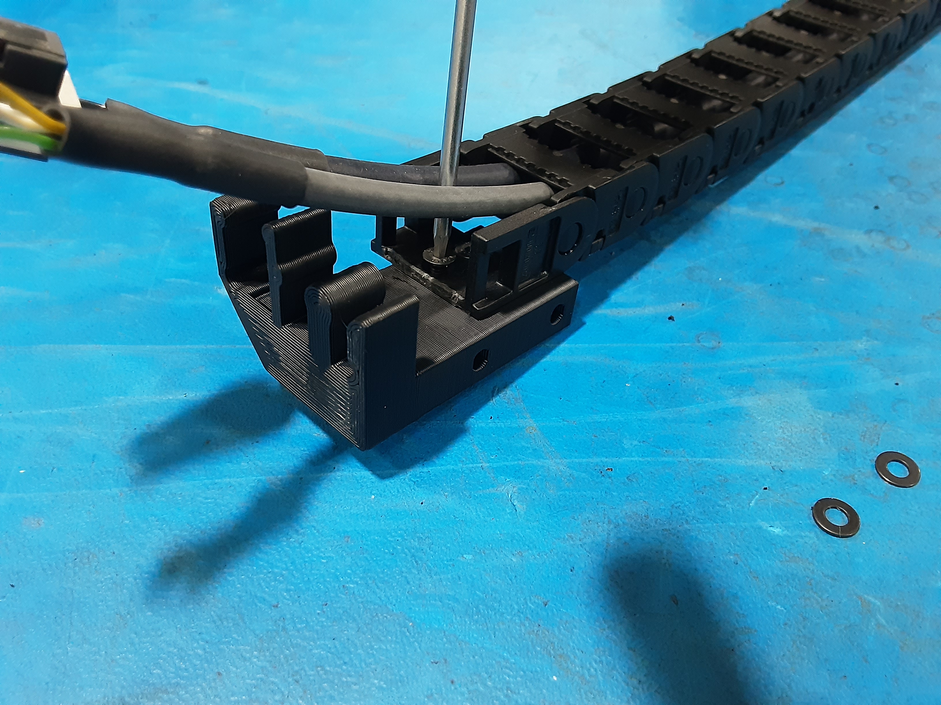
6D) Attach PP-GP0801 to the other side of the AS-CB0218 chain using HD-BT0128 x2.
6E) Attach PP-GP0801 to the bottom of the F.A. using HD-BT0157 x2 and HD-WA0038 x2.
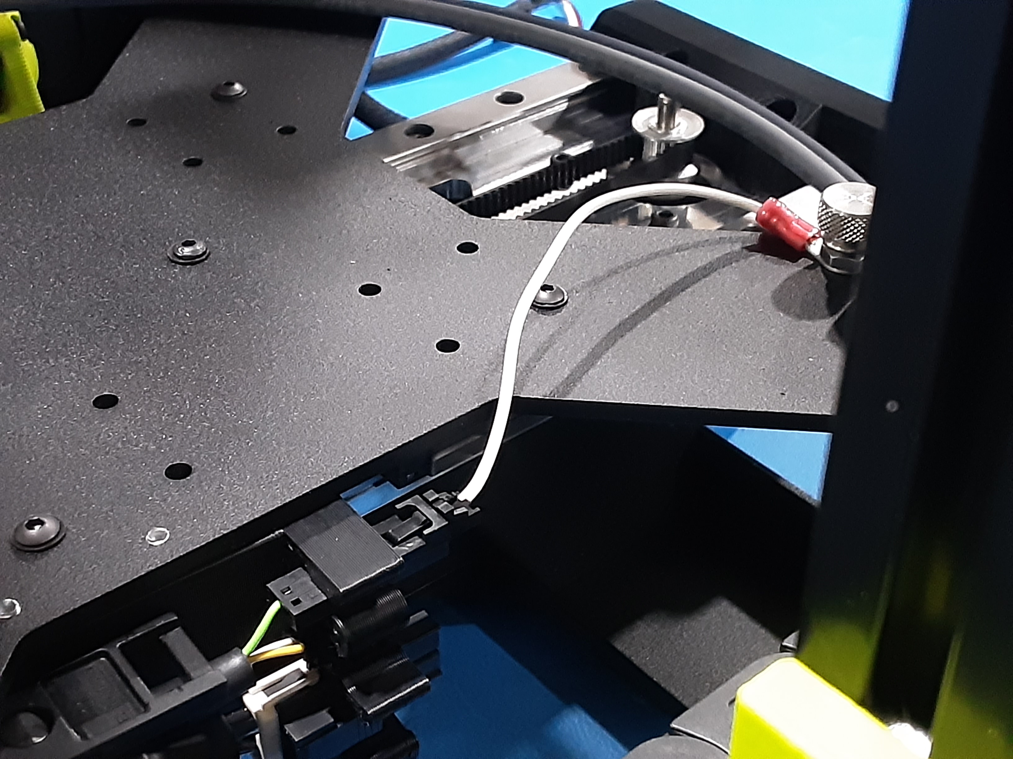
6F) Attach PP-GP0805 to PP-FP0237 from Y.A.B. using HD-BT0041 x2.
6G) Connect EL-HR0228 from Y.A.B. to AS-CB0218.