Open HardwareAssembly Instructions
Guides for installation and assembly of the LulzBot line of products made by FAME 3D LLC.
Guides for installation and assembly of the LulzBot line of products made by FAME 3D LLC.
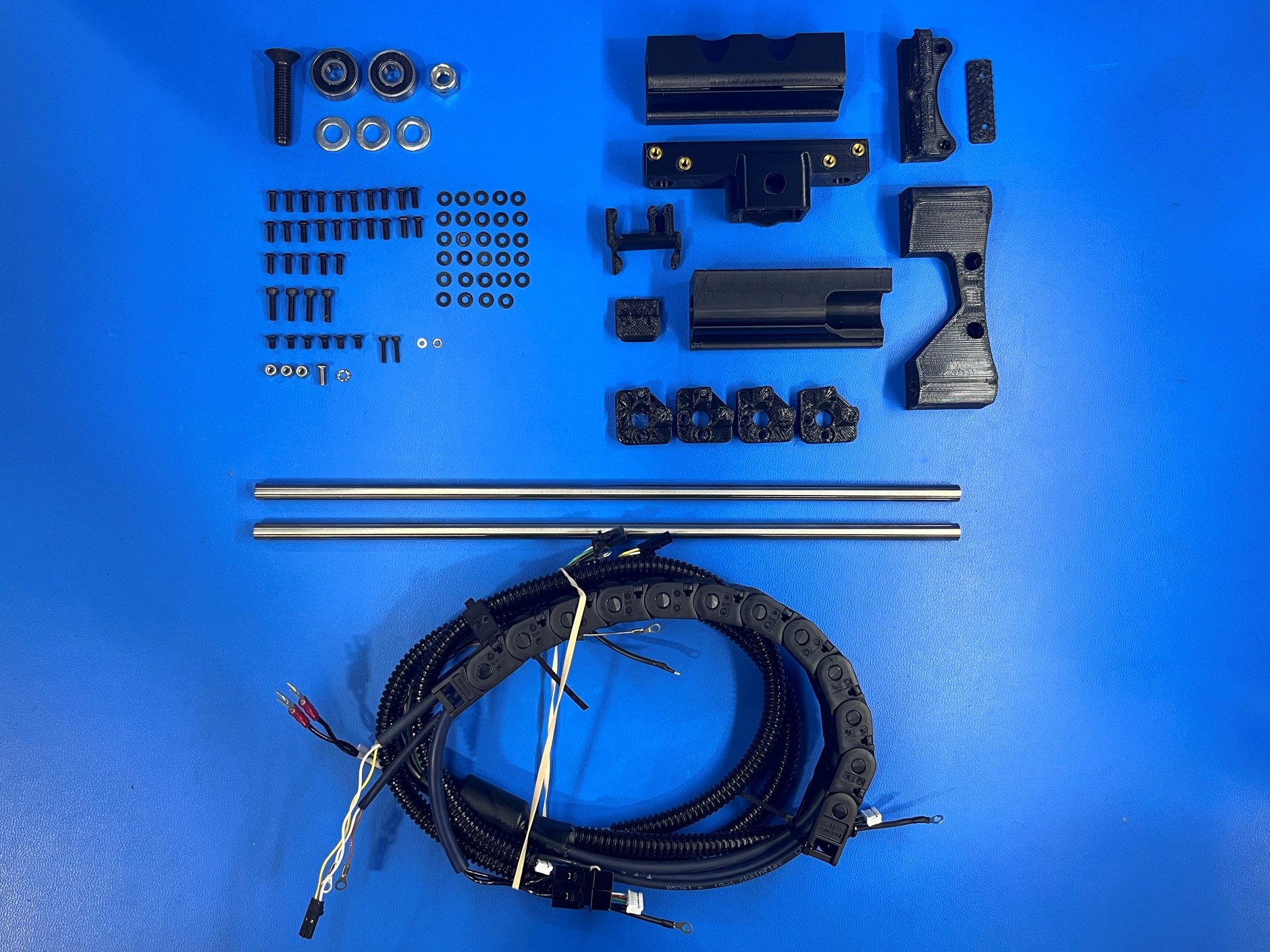
1x- [AS-CB0071] Mini 2 Bed Harness
4x- [HD-BT0039] M3x12 SHCS, Black-Oxide
1x- [HD-BT0104] M3x8 BHCS, SST
2x- [HD-BT0107] M2x10 SHCS, Black-Oxide
1x- [HD-BT0117] M8x40 FHCS, Black-Oxide
6x- [HD-BT0128] M3x6 FHCS Black-Oxide
25x- [HD-BT0137] M3x8 BHCS, Black-Oxide
2x- [HD-MS0282] 608-2RS Rubber Sealed Bearing
3x- [HD-NT0001] M3 Locknut
1x- [HD-NT0002] M8 Locknut
2x- [HD-RD0035] 8mm Smooth rod, 315mm
3x- [HD-WA0006] M8 Washer
2x- [HD-WA0012] M2 Washer
1x- [HD-WA0035] M3 External Tooth Lock Washer
29x- [HD-WA0038] M3 Washer
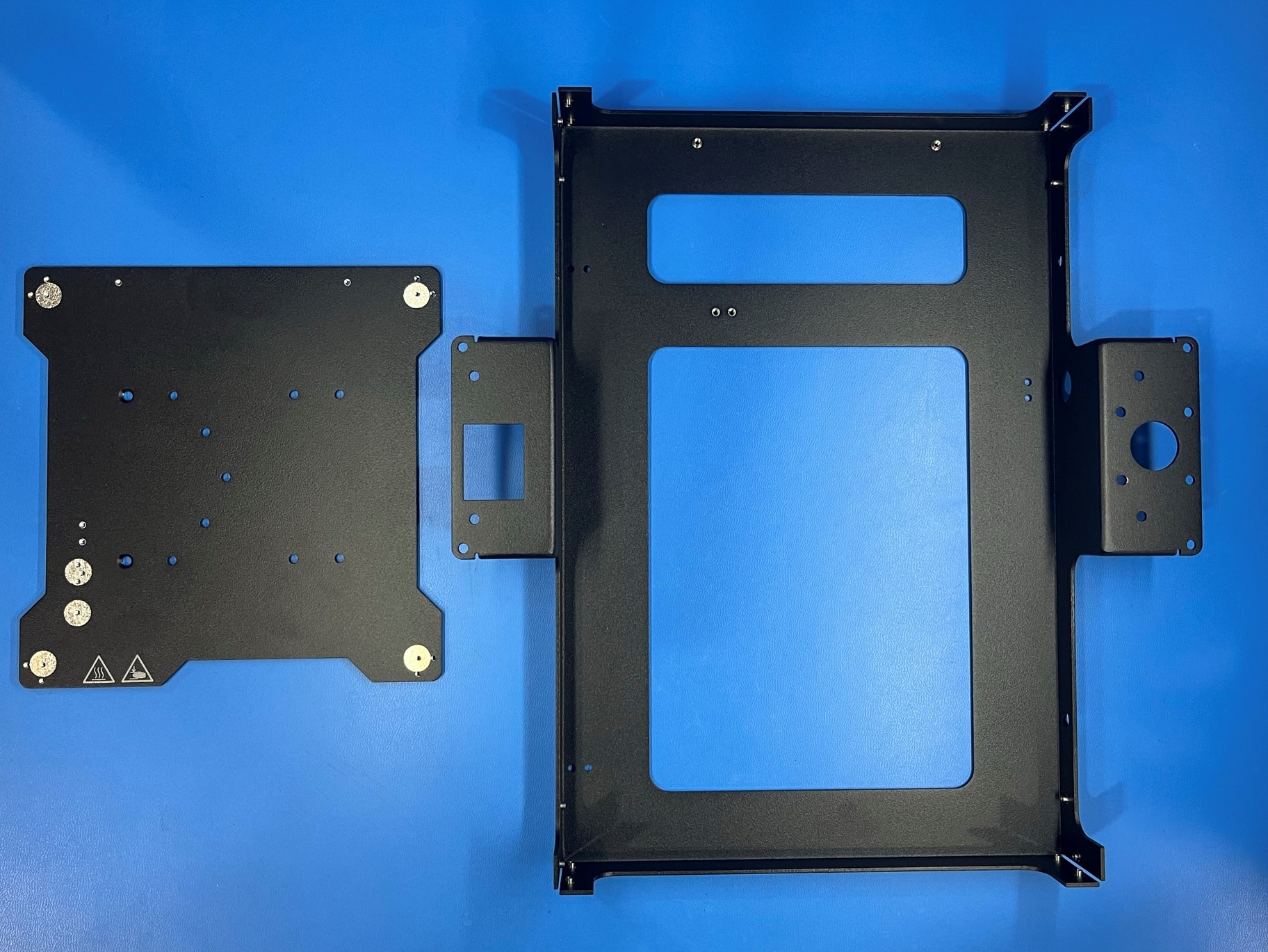
1x- [PP-FP0138] Silk Screened Bed Mount Plate, Mini
1x- [PP-GP0133] Mini, Double Bushing Holder
1x- [PP-GP0134] Mini, Single Bushing Holder
1x- [PP-GP0249] Bed Clip
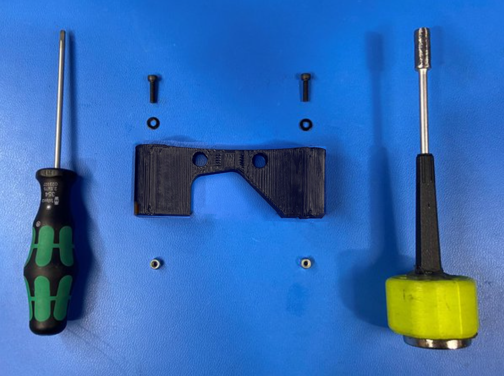
1x- [PP-GP0263] Mini, Y Motor Mount
1x- [PP-GP0264] Y Idler
1x- [PP-GP0277] Belt Clamp
1x- [PP-GP0278] Belt Mount
1x- [PP-GP0332] Bump Stop
4x- [PP-GP0335] Flexy Bed Corner
1x- [PP-MP0149] Bottom Frame Plate
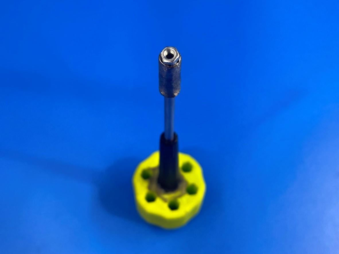
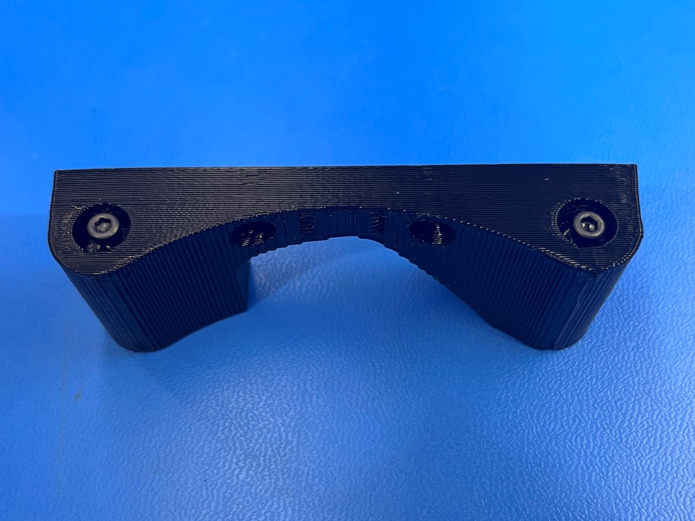
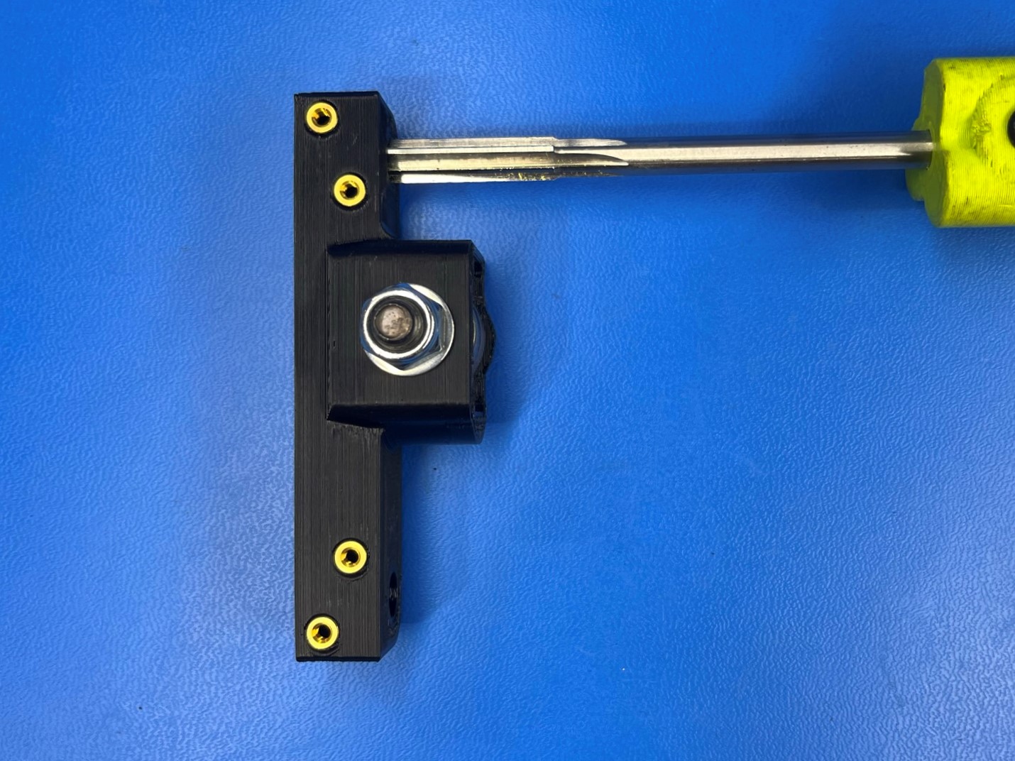
Put the M3 nyloc nut [HD-NT0001] into the 5.5 mm nut driver that has been ground down to 7.5mm in order to fit inside the Y-Rod Mount.
Insert the 5.5mm nut driver into the longer hold of the Y-Rod Mount. Make sure you press the driver to the bottom of the bore.
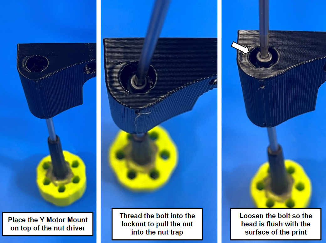
Then, use a M3 x 12 SHCS [HD-BT0039] and an M3 washer [HD-WA0038] to pull the nyloc into the hexagon shaped hole in the printed Y-Rod Mount [PP-GP0263] with a 2.5 mm hex driver or electric screwdriver.
Inspect the nyloc nut to make sure it is seated into the nut trap correctly.
Back the screw out until it is flush with the printed part, and then repeat this process for the other side of the printed part.
Torque to 10-15in*lbs when pulling the nyloc into nut trap


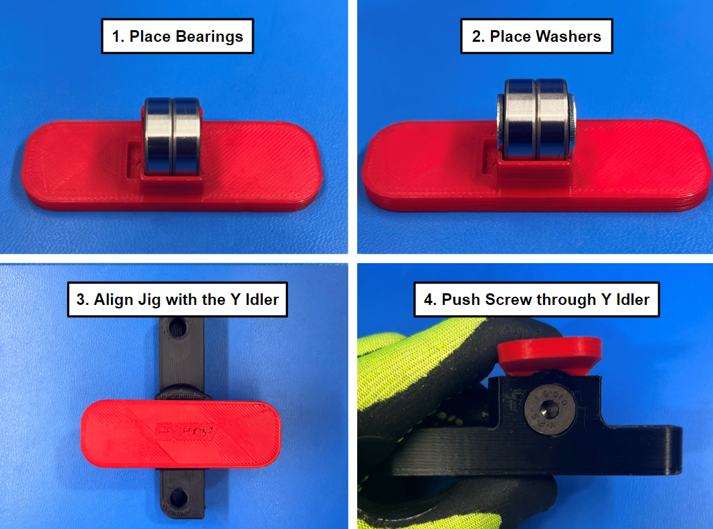
Place 2x bearings [HD-MS0282] inside the Y idler jig then set 2x M8 washers [HD-WA0006] next to the bearings.
Put a M8x40 FHCS [HD-BT0117] through the countersunk hole in the printed Y idler part [PP-GP0264].
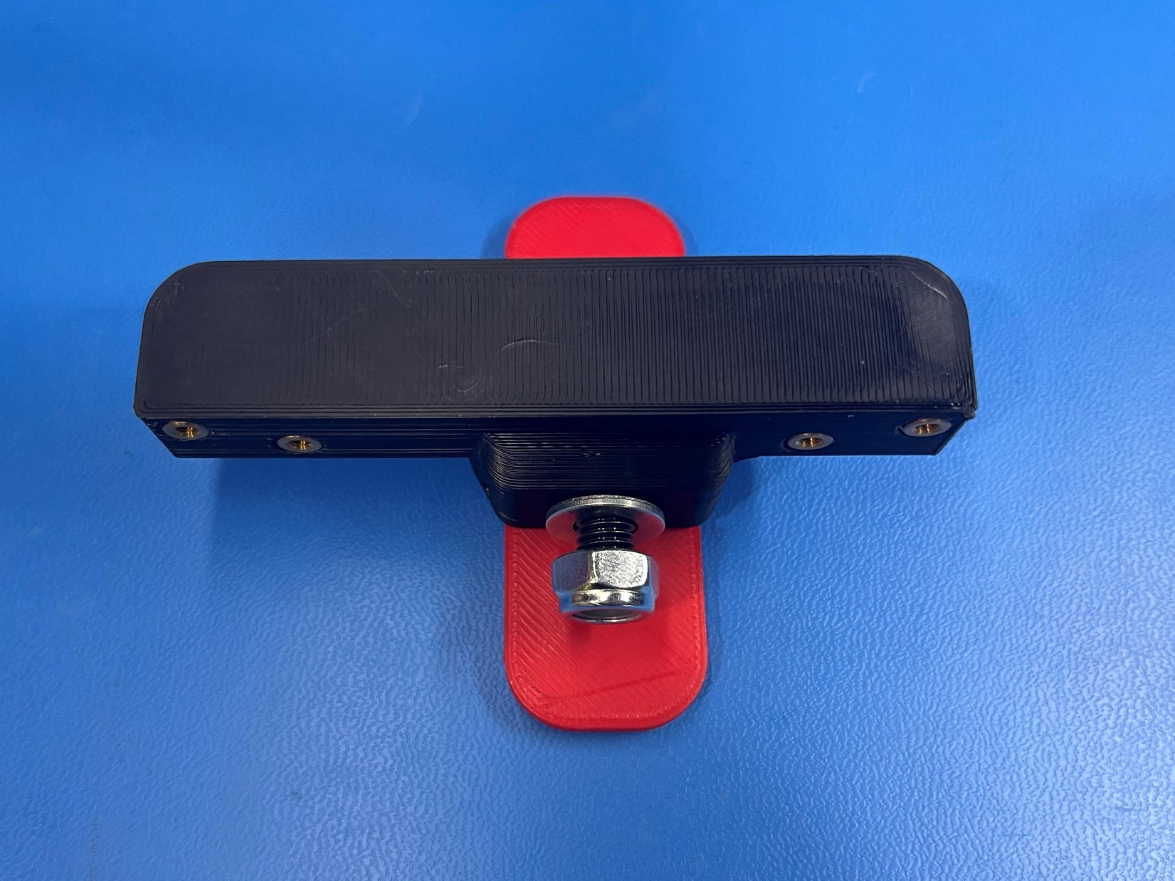
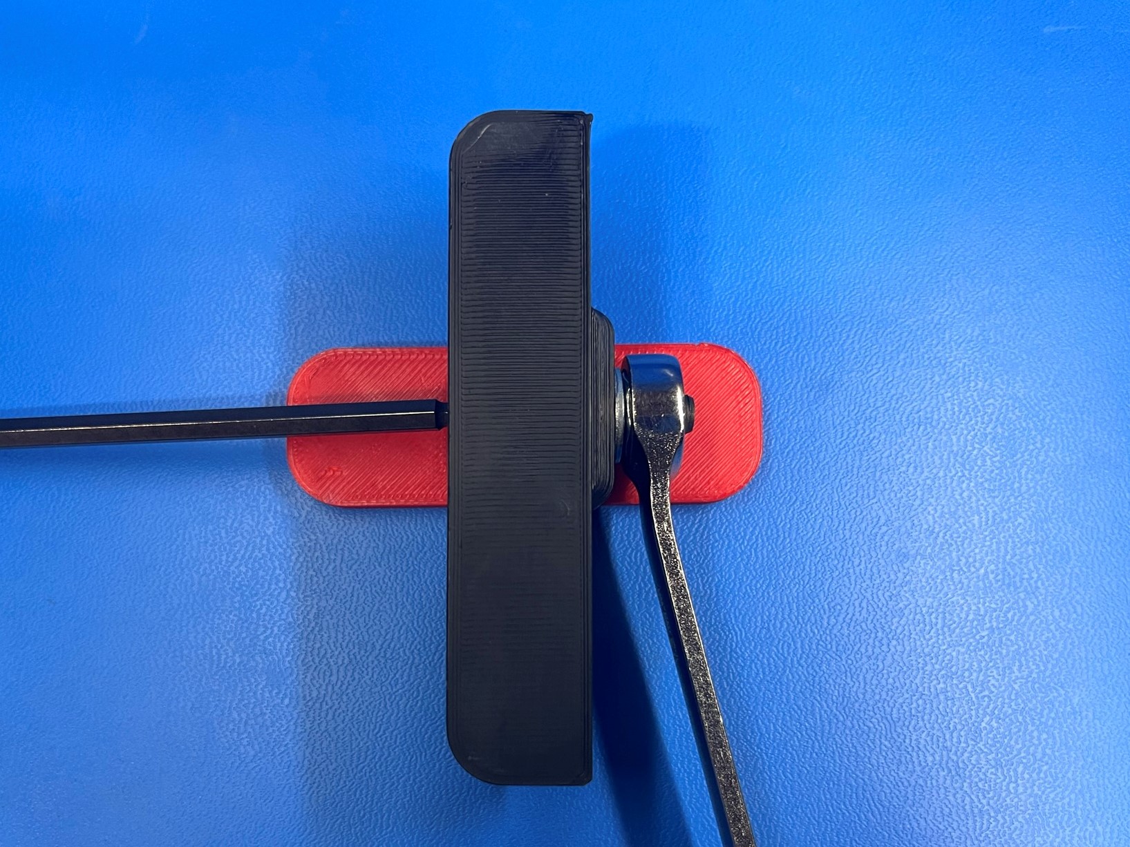
Place an M8 washer [HD-WA0006] and an M8 locknut [HD-NT0002] on the end of the M8x40 FHCS. Use a 5mm driver and a 13mm wrench to turn the nut onto the bolt.
Fasten bolt until nut is tight against the washer and bearing can freely spin, but do not tighten it.
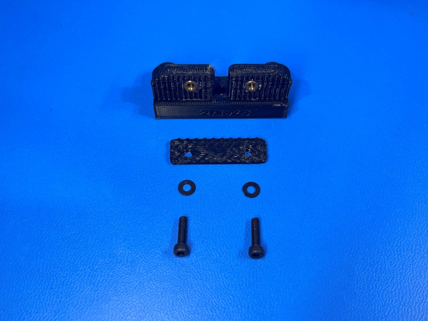
Using 2x M2x10 SHCS [HD-BT0107] with M2 washers [HD-WA0012] fasten 1x bump stop [PP-GP0332] to the single bearing holder [PP-GP0134]. The round side of the bump stop will hang over the side of the single bearing holder.
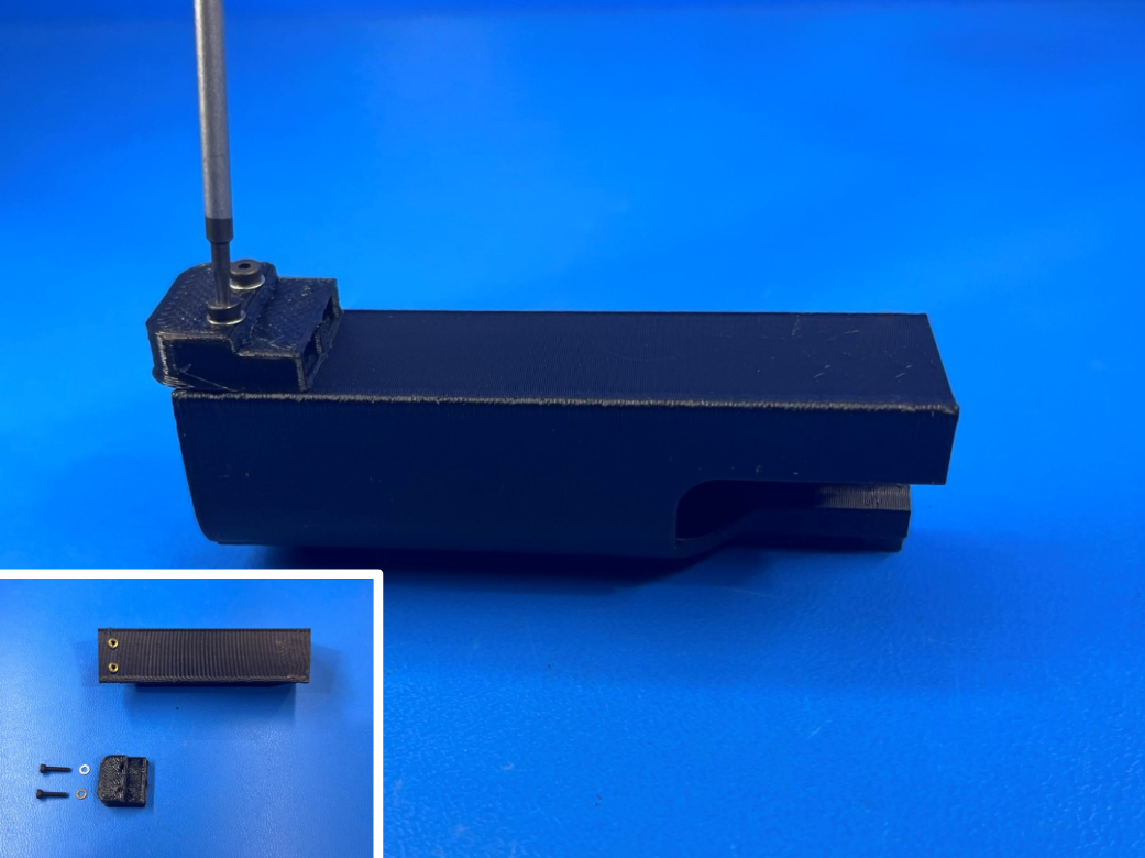
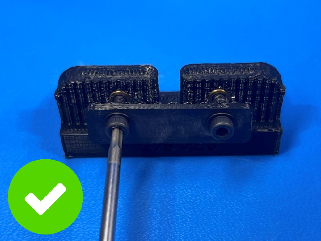
Attach the belt clamp [PP-GP0277] to the belt mount [PP-GP0278] using 2x M3x12 SHCS [HD-BT0039] with M3 washers [HD-WA0038] with the wider side towards the base of the mount. Leave the screws loose as they will be tightened at the Final Mechanical Assembly.
Make sure to install the belt clip with the treads on the inside to grip the belt

Use the printed bed plate jig to install the bushing holders and belt clamp. With the ground side closest to you, place the single bushing holder [PP-GP0134] on the left side. The bump stop should fit into the indents of the jig.
Then place the double bushing holder [PP-GP0133] on the right side with the cutouts facing the center of the jig.
Place the belt clamp assembly in the center with the flat edge and screws to the left.
Set the bed mount plate on top with the ground screw in the bottom left corner.
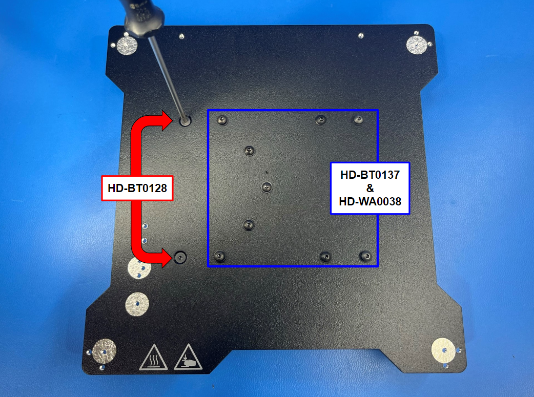
Secure the left half of the single bushing holder with 2x M3x6 FHCS [HD-BT0128].
Then secure the left side of the single bushing holder, belt clamp, and the double bushing holder using 9x M3x8 bolts [HD-BT0137] with M3 washers [HD-WA0038].
Tighten the right side of the single bearing holder and the belt clamp, but leave the other screw loose.


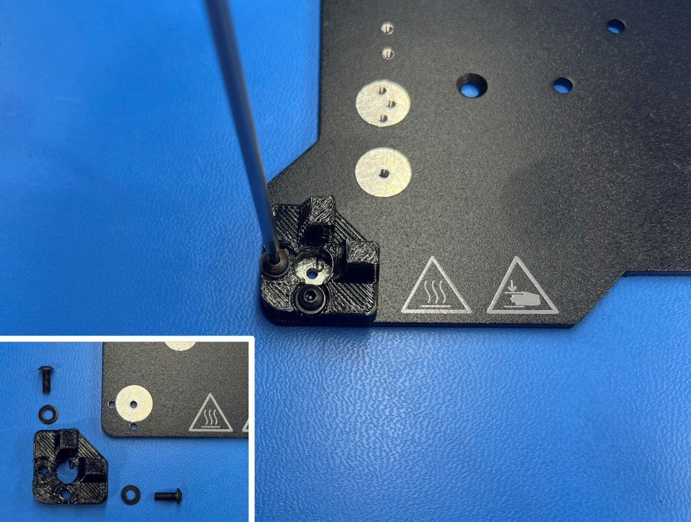
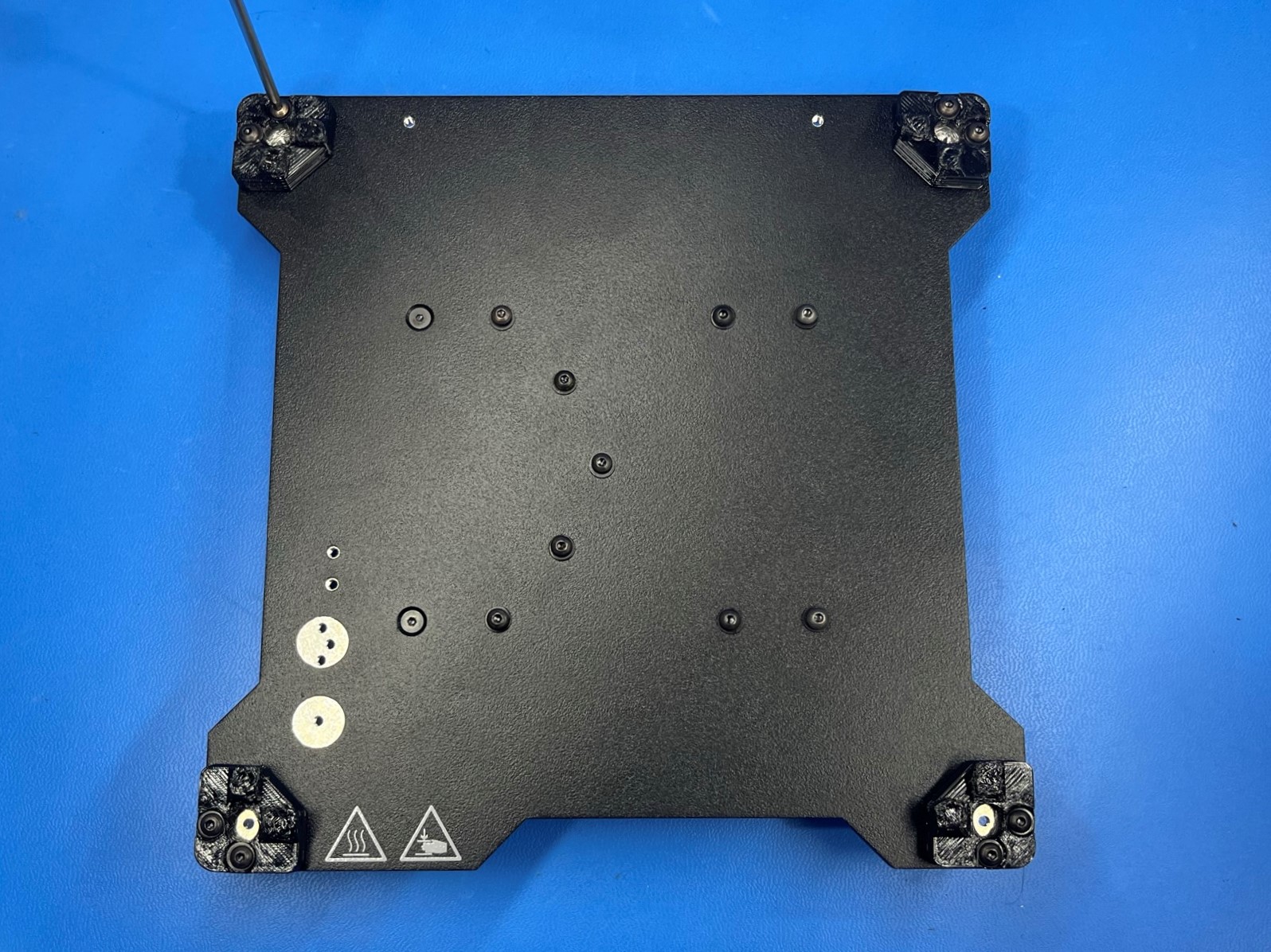
Using 2x M3x8 BHCS [HD-BT0137] and 2x M3 washers [HD-WA0038] fasten 1x flexy bed corner [PP-GP0335] to the bed mount plate [PP-FP0138].
Then repeat step for the other three bed corners.
These may be left loose for the time being; they will be tightened in position with the bed heater at Calibration.
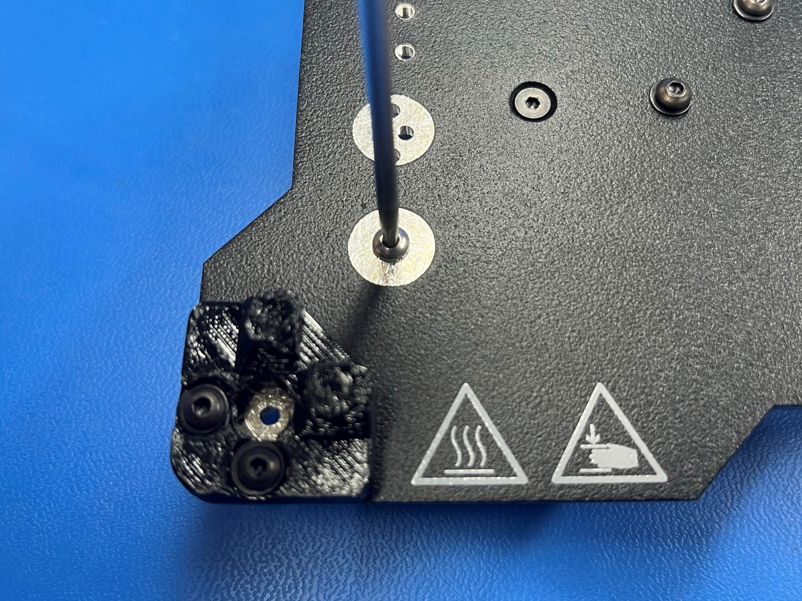
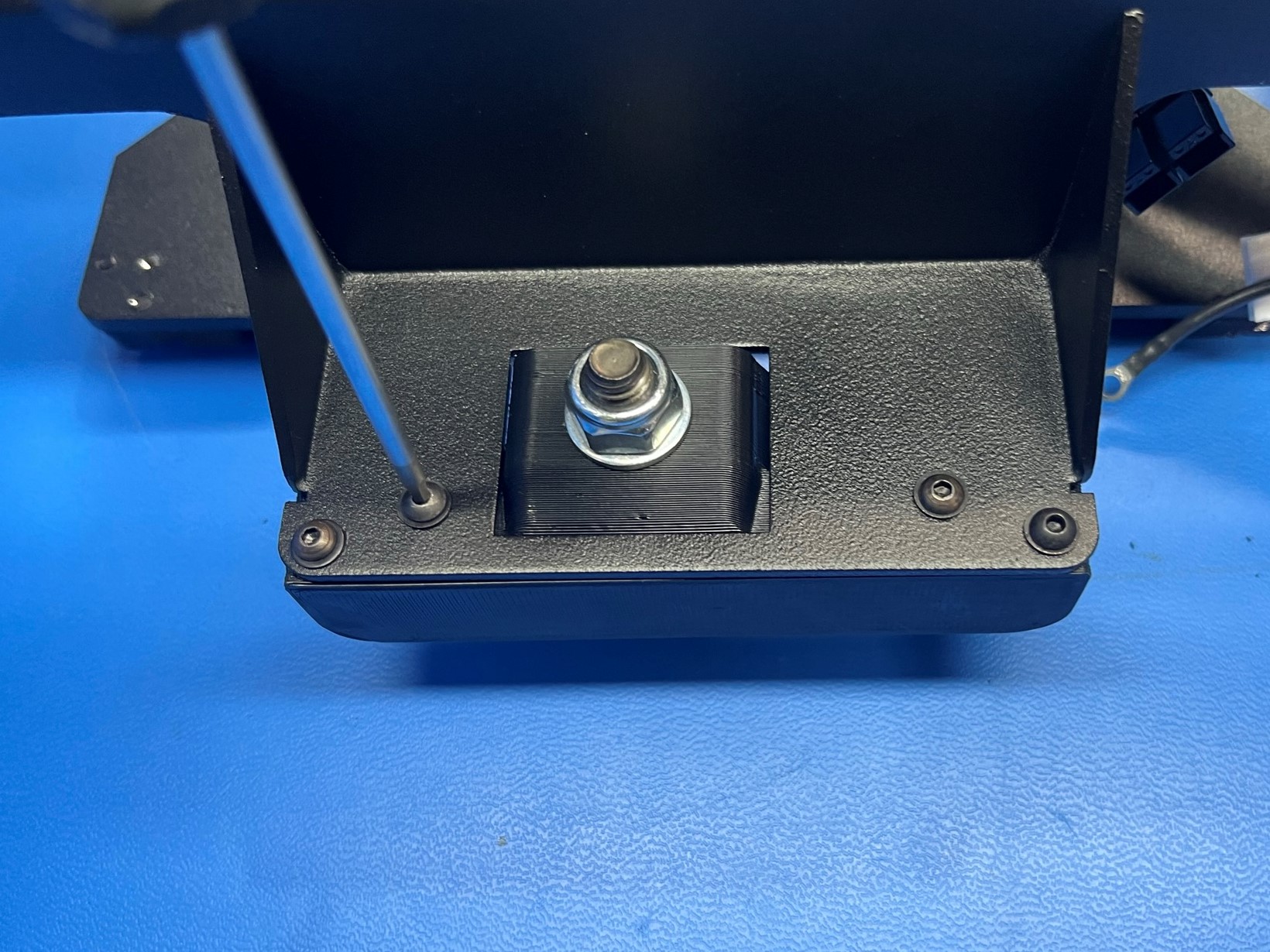
Once all the bed corners are attached to the bed mount plate fasten the M3x8 BHCS [HD-BT0104] into the hole in the center of the silver circle
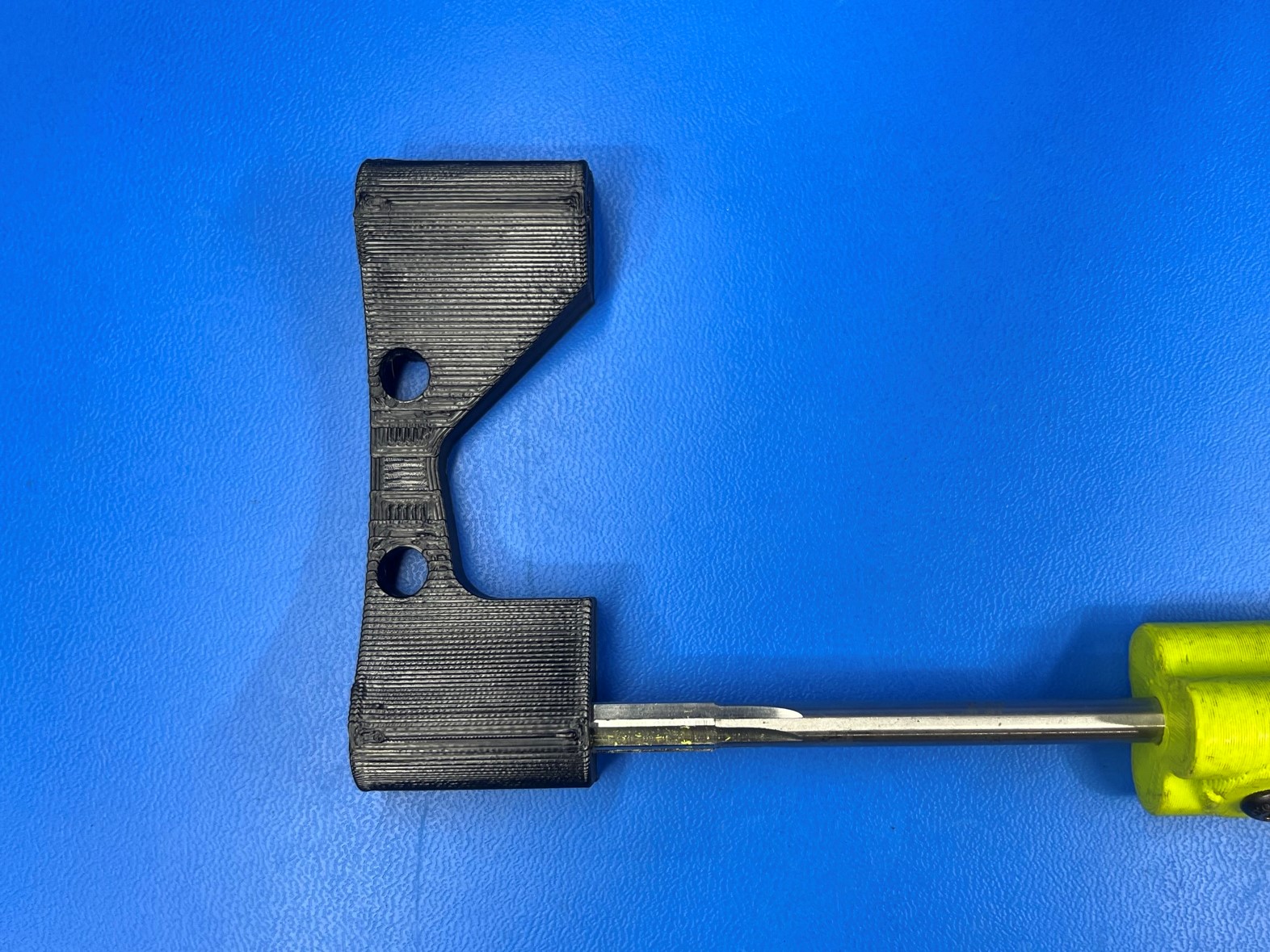
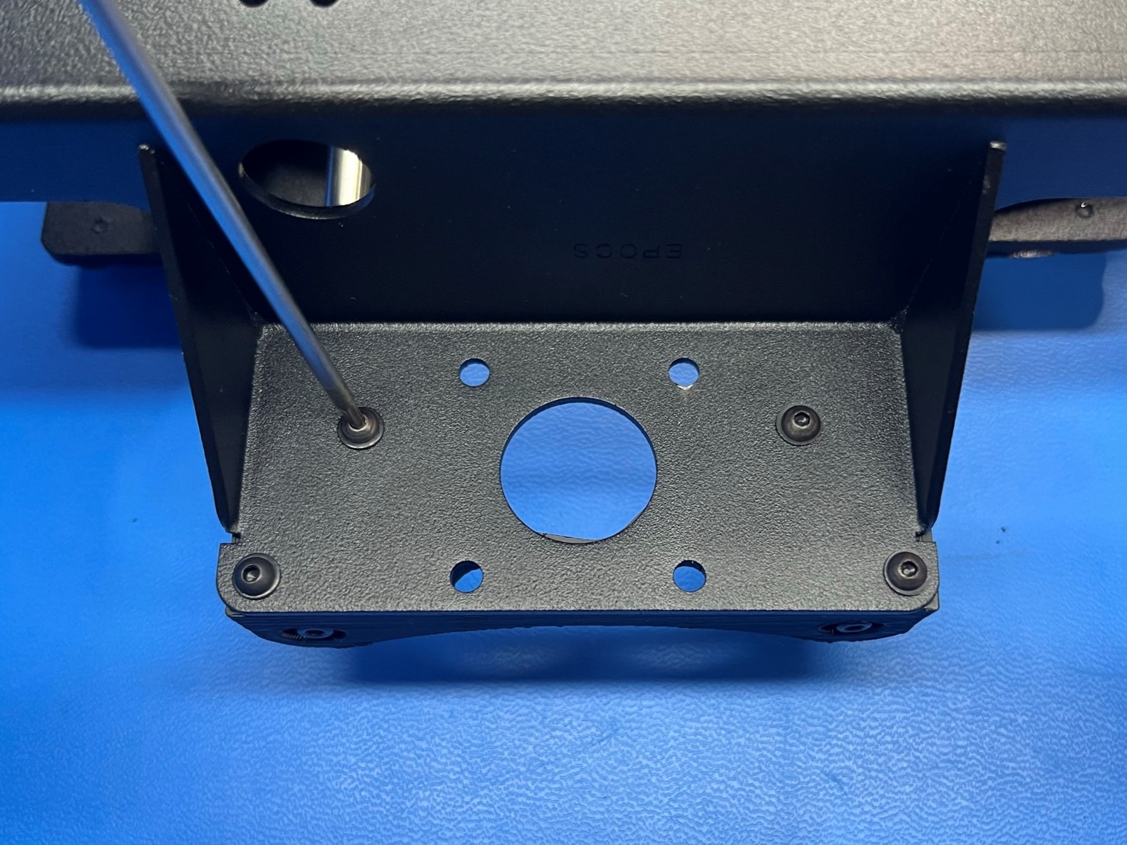
Use the 8 mm reamer to gently ream the Y motor mount [PP-GP0263]. Take care to keep the tool straight and to not remove too much material which would result in a loose fitting rod.
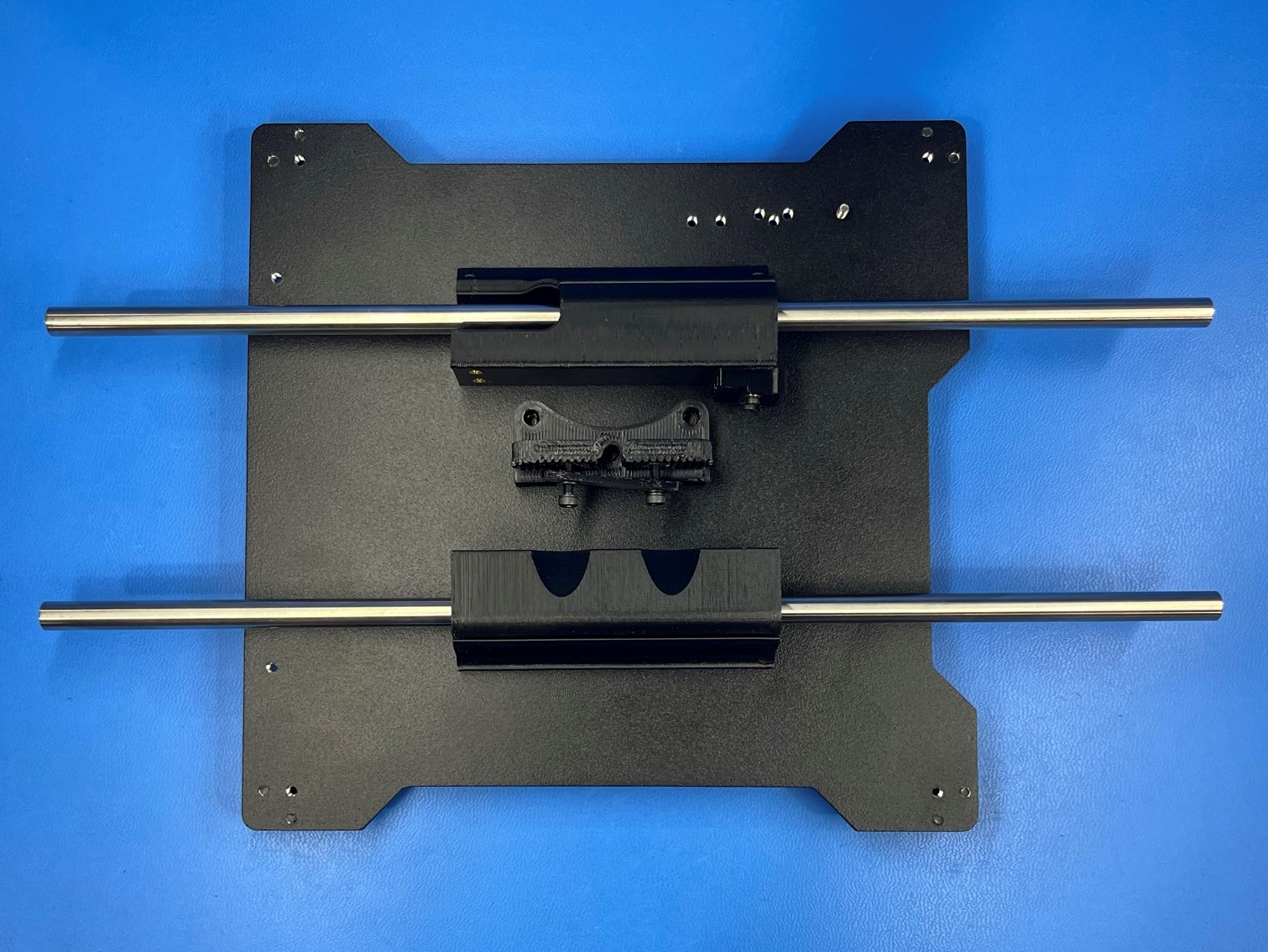
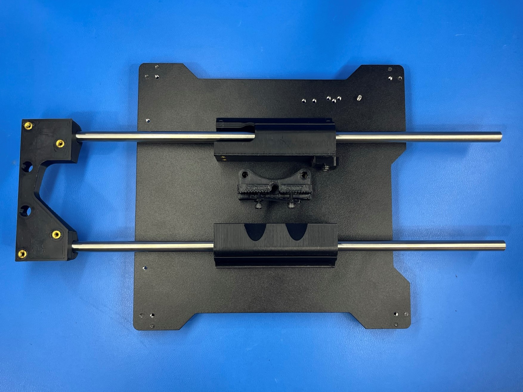
Take note of the orientation of the bushing holders shown in the picture.
Slide 2x smooth rods [HD-RD0035] into the double and single bearing holders.
Then take the Y motor mount and slide it on the end of the rods making sure its closest to the ground screw on the bed plate. If the rods do not seat, it might be a sign that the reamer tool needs to be used to clean up the hole in the printed part.
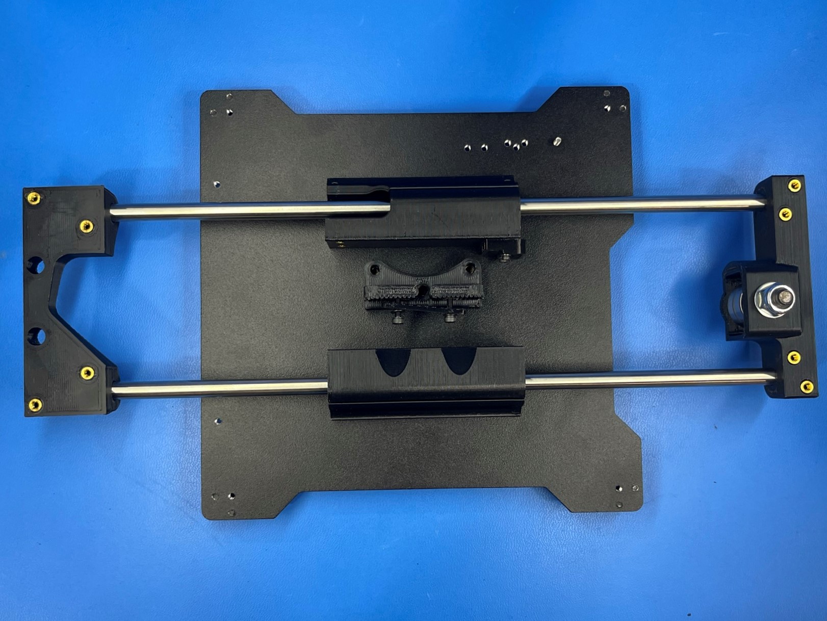
Now take the Y idler [PP-GP0264] and slide it on the other end of the rods.
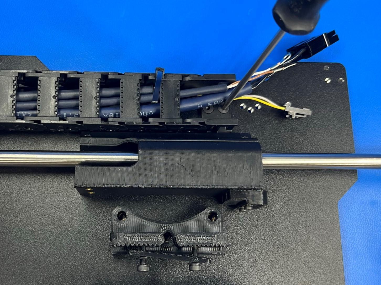
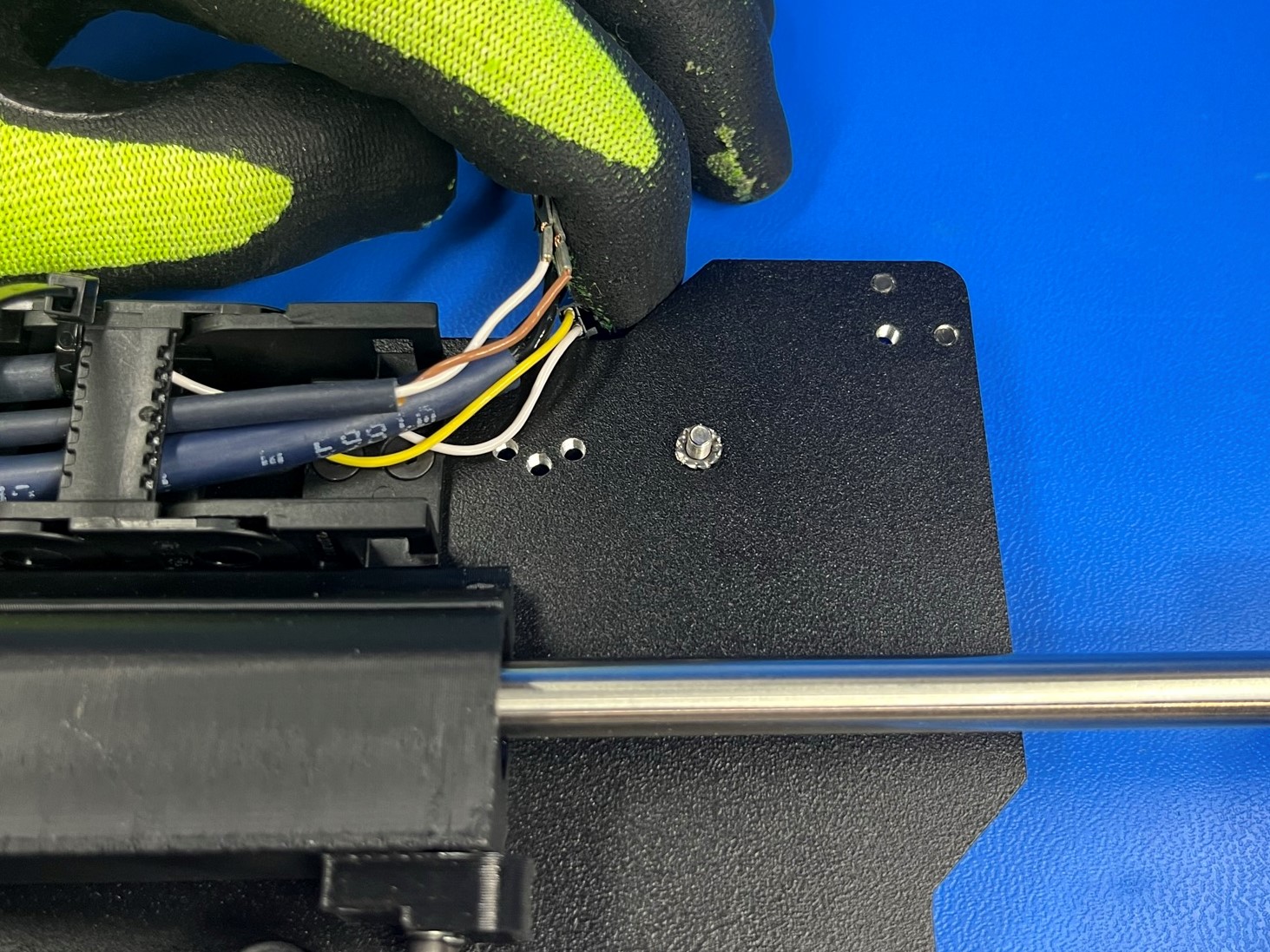
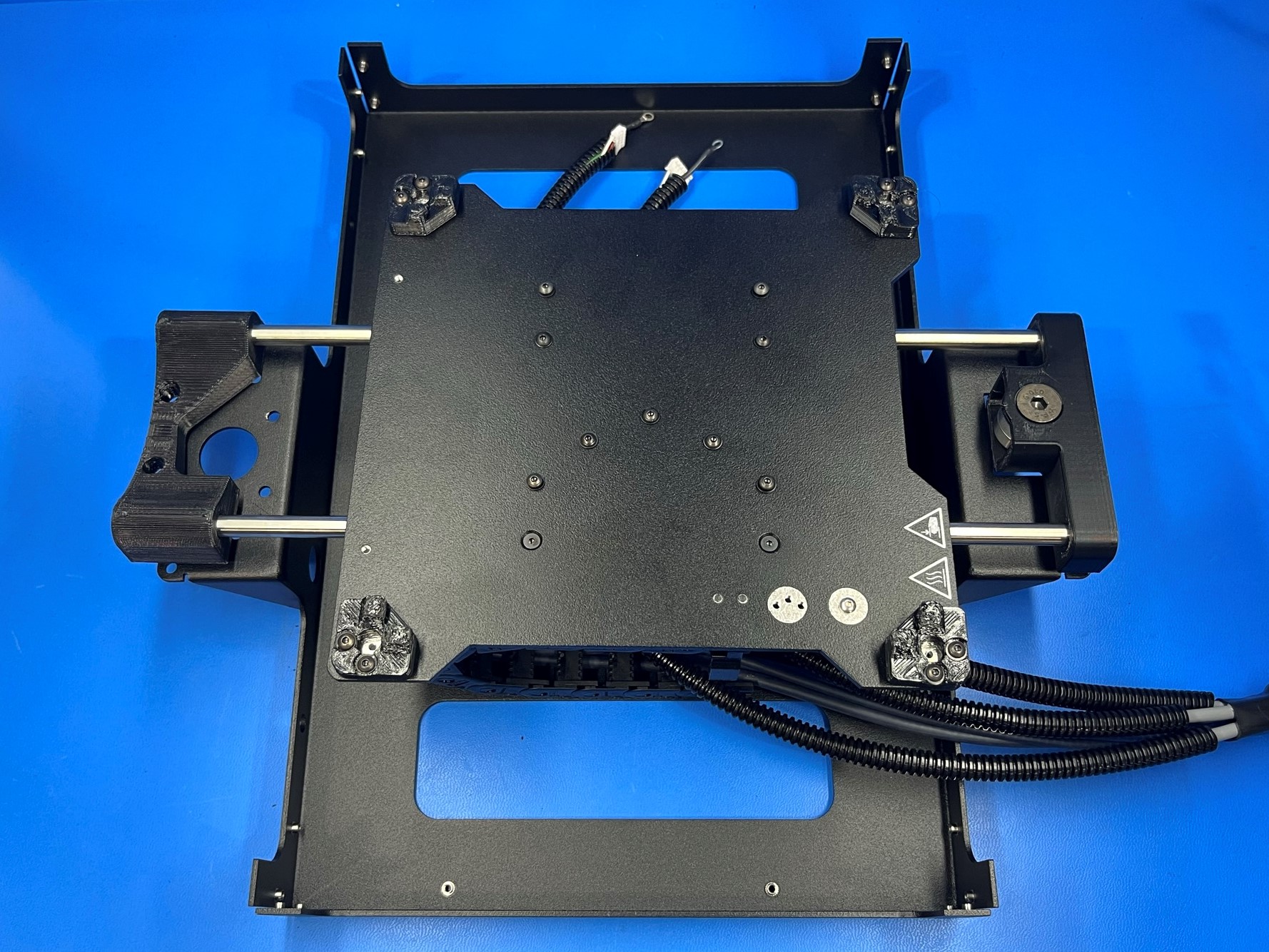
Using 2x M3x6 FHCS [HD-BT0128] attach the Mini 2 bed harness [AS-CB0071] to the bed plate. Use the end of the cable chain that has the wire connectors.
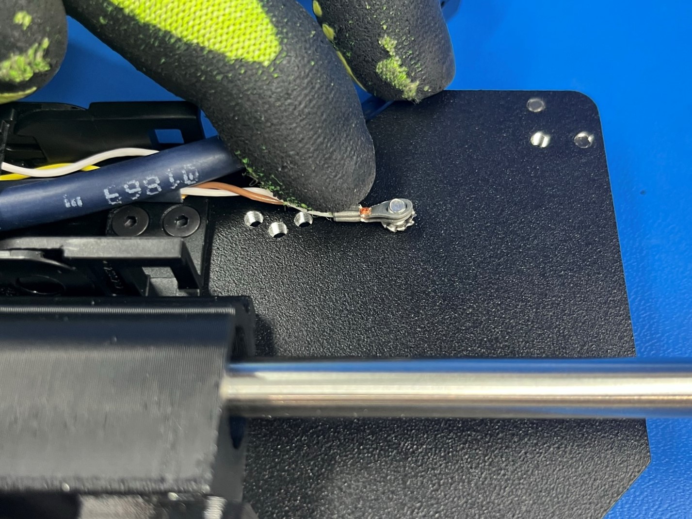
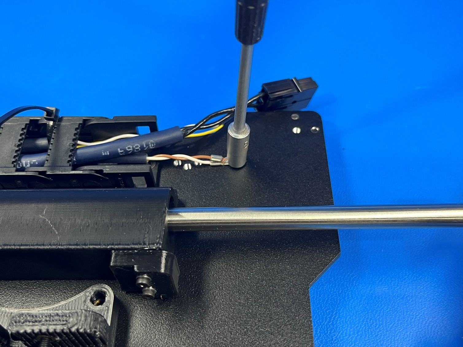
Place 1x M3 internal tooth lock washer [HD-WA0035] and the brown and white grounding wires around the grounding screw and tighten with 1x M3 locknut [HD-NT0001].
Then place the bed clip [PP-GP0249] at the end of the cable chain with the flat side on the end of the cable chain.

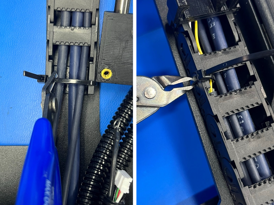
Remove the preinstalled cable ties from the cable chain.
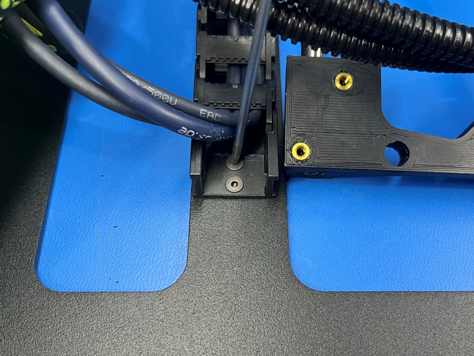
Align the cable chain mount with the two holes in the bottom frame plate [PP-MP0149] and secure using two M3x6 FHCS [HD-BT0128].
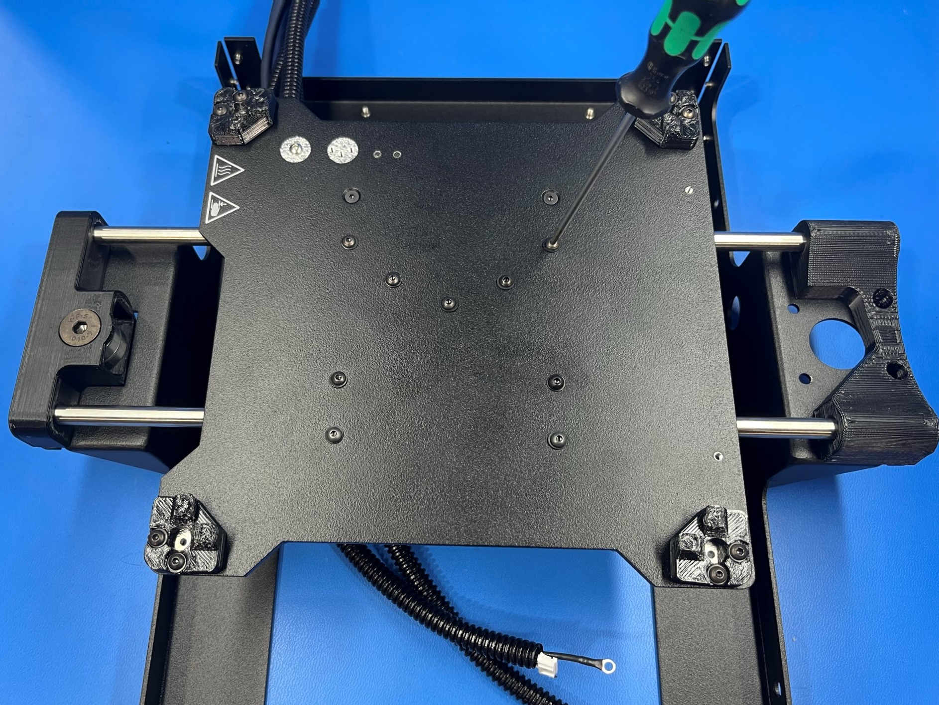
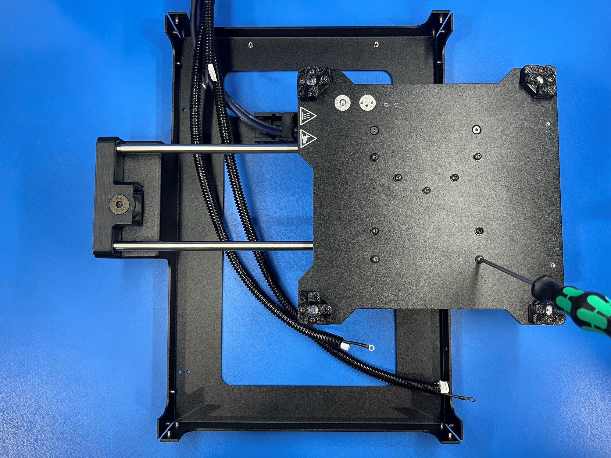
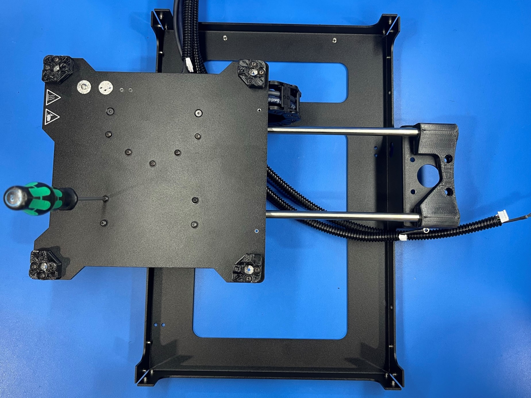
Flip the bed plate assembly so the bed plate is resting on the table, then carefully flip the bottom frame plate and bed plate into position as shown.
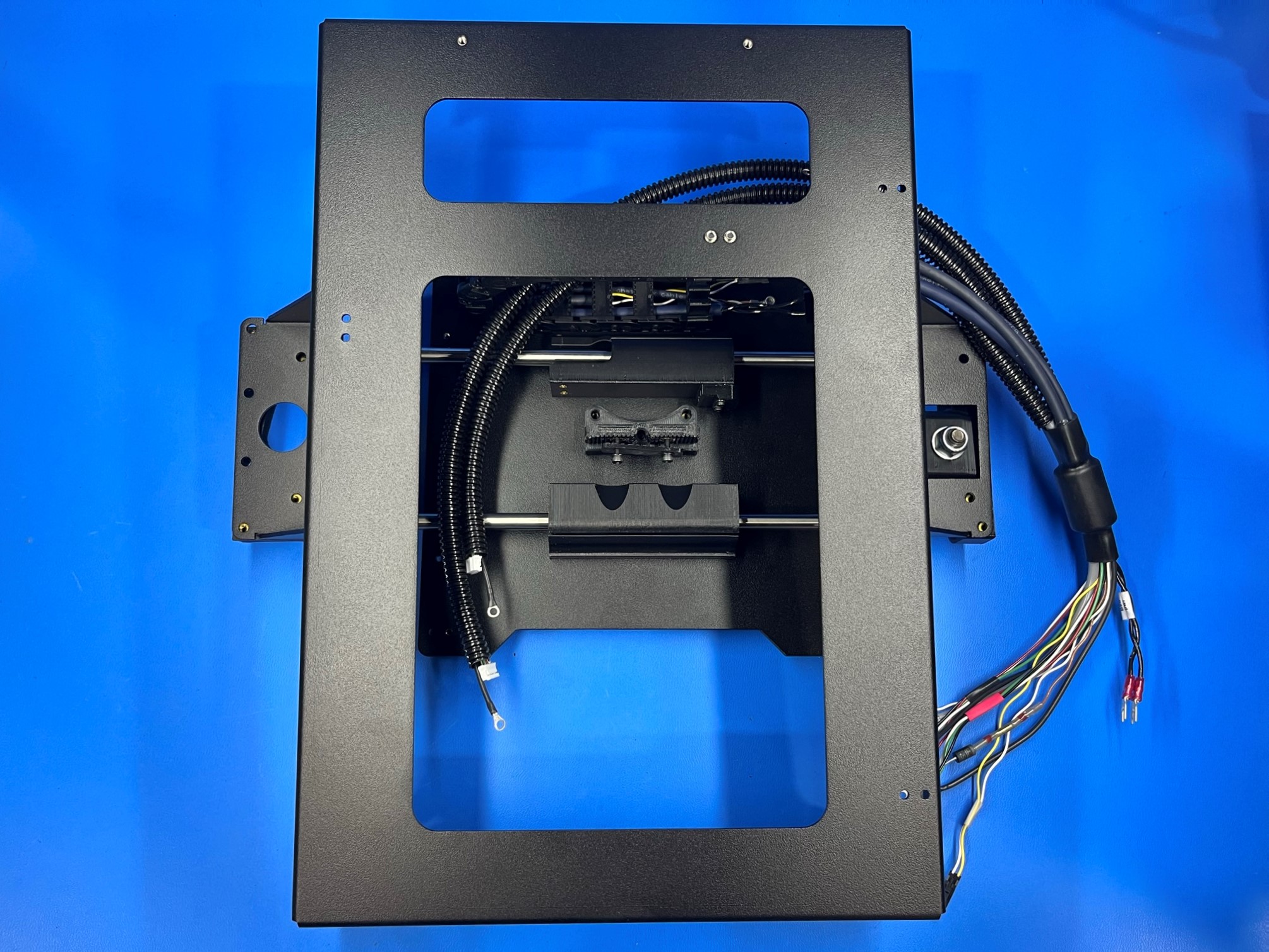
Using 4x M3x8 BHCS [HD-BT0137] with M3 washers [HD-WA0038] secure the Y axis idler to the bottom frame plate.
Make sure the front of the Idler printed part remains flush with the idler mount of the Frame.
Secure the Y motor mount to the motor mount flange of the bottom plate using 4x M3x8 BHCS [HD-BT0137] with M3 washers [HD-WA0038].
Make sure the back of the Y motor mount remains flush with the motor mount flange of the frame.
Flip the assembly over so the bed plate is on top, and tighten the two loose screw holding the single bearing holder.
Then slide the bed plate all the way towards the Y motor mount until it stops. Then tighten one of the screws holding the double bearing holder.
Now slide the bed plate the other way until it stops so that its covering the Y idler. Then tighten the screw that diagonal from the screw that was previously tightened.
Slide the bed plate assembly to the middle of the rods and tighten the other two screws.