Open HardwareAssembly Instructions
Guides for installation and assembly of the LulzBot line of products made by FAME 3D LLC.
Guides for installation and assembly of the LulzBot line of products made by FAME 3D LLC.
By purchasing a LulzBot TAZ Dual Extruder v3 Tool Head, you're ready to begin combining colors and textures with support material for unique prints that are sure to turn heads. Follow the steps below to install your LulzBot TAZ Dual Extruder v3 Tool Head on your TAZ 5 and explore the possibilities of printing with full geometric freedom.
Note: Be sure you are using the correct OHAI guide! The Dual Extruder v3 installation guide for TAZ 6 users can be found here
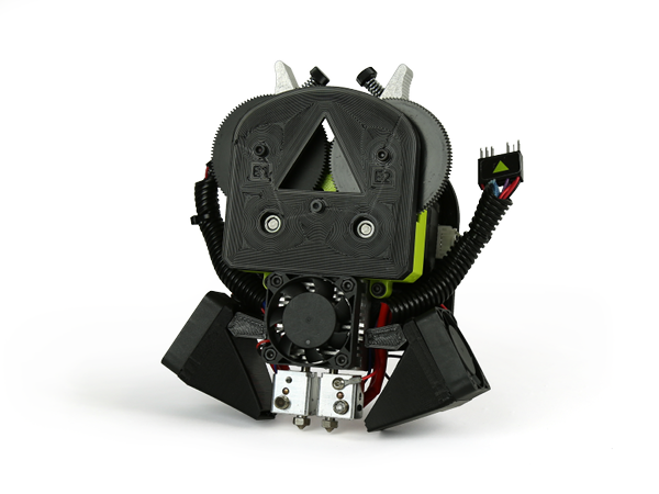
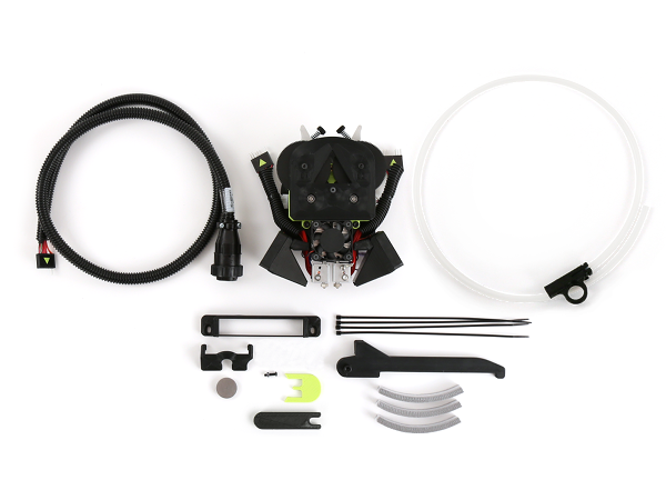
(1) LulzBot TAZ Dual Extruder v3 Tool Head
(1) Additional spool arm
(1) Feed tube spinner
(1) T-nut holder jig
(1) Idler jig
(1) Machined Z-axis endstop extension (for TAZ 6)
(1) 3D Printed Z-axis endstop extension mount (for TAZ 6)
(1) Dual v3 wiper mount (for TAZ 6)
(4) Wire tie
(1) M5 x 14 socket head cap screw (TAZ 5)
(2) Extension harnesses
(1) M5 washer (black)
(1) Feed tube
You will also need
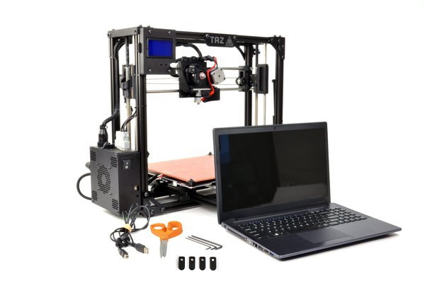
Let's get started!
4A
Power on your LulzBot TAZ 5 3D Printer.
4B
Home your 3D printer by using the Graphical LCD controller to home the printer.
4C
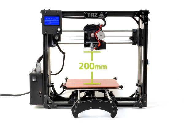
Raise the Z-axis through the Graphical LCD controller.
4D
Navigate to:
Prepare > Move Axis > 1.0 > Z-axis > Change the value to at least 200.
4E
After the Z-axis stops moving, push the X-axis carriage over by hand to the middle of the X axis.
5A
Completely power off your LulzBot 3D Printer and unplug the power supply before proceeding.
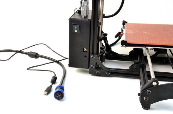
Additional clearance is necessary for the extrusion fan ducts on your new dual extruder.
6A
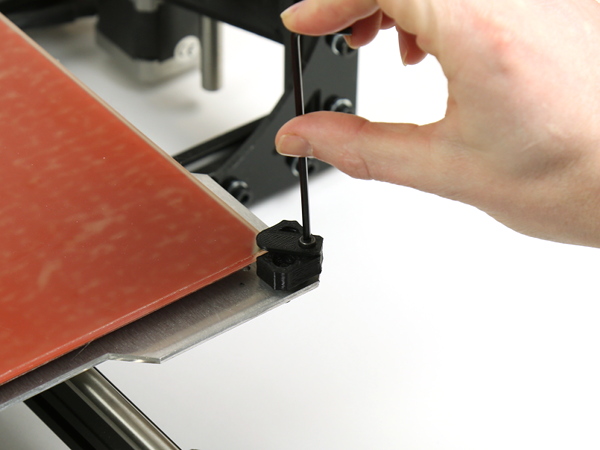
Remove the four original 3D printed bed corner fingers using a 2.5 mm hex driver.
7A
Using a 2.5 mm hex driver and the screws removed in the previous step, replace the bed corner fingers with the 3D printed lower profile bed corner fingers.
The recessed side of the bed fingers should be facing up.
8A
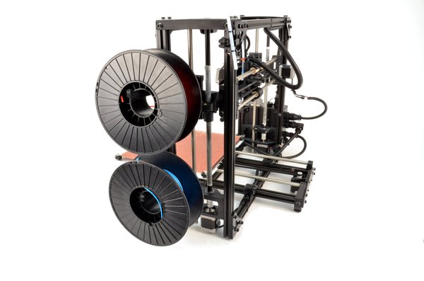
Loosen the existing spool arm and slide it down about 2 inches (50 mm), and tighten it.
8B
Insert the new T-nut included with your Dual Extruder Tool Head v3 on the same Z-axis vertical frame (the front right extrusion), in the same channel.
8C
Use the M5 screw to install the 3D printed secondary filament spool arm.
8D
Place two spools of filament on the spool arms to ensure they are mounted with sufficient space to rotate during printing.
8E
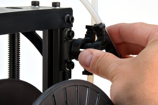
Attach the secondary filament guide tube included with your new dual extruder, matching the existing feed tube orientation.


9A
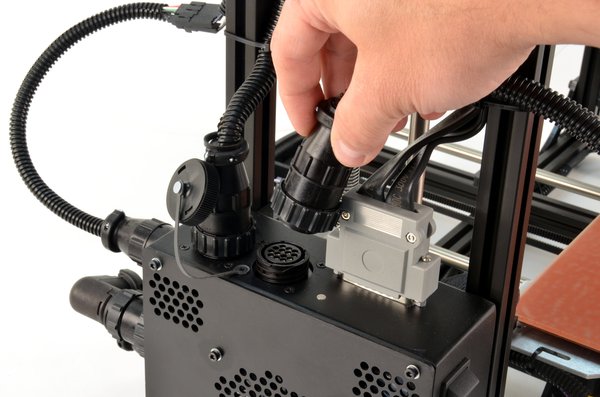
Unscrew the cap on the second port on top of the electronics box on your LulzBot TAZ 5 3D Printer, then plug in the secondary extruder harness into the uncapped port.
9B
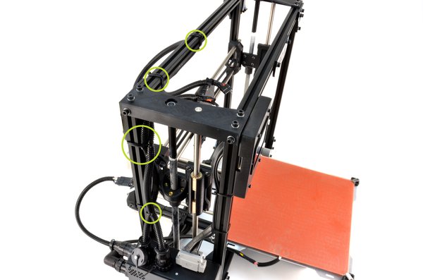
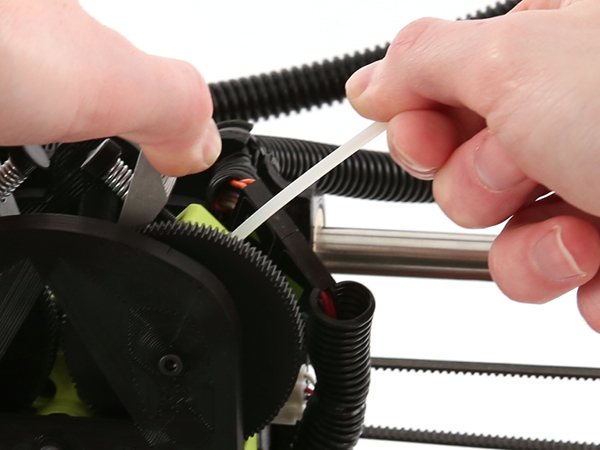
Route the new harness next to existing one on your printer, using wire ties to secure it in the same spots.
9C
Use a zip tie to secure the new secondary extruder harness into the empty harness holder on the top-left side of the x-carriage.
Note: Correct functionality can be tested by giving a command to Extruder 1 in Cura, and then watching to be sure Extruder 1 executes the command on the printer.
10A
Unplug the connectors for your current tool head.
10B
With one hand support the tool head and unscrew the single M3 screw securing it to the X-axis carriage.
10C
Remove the tool head from the 3D printer by lifting the tool head up.
Note: In previous versions of our tool heads, the Esteps were listed along the back of the tool heads for the customer to update. For the new v3 tool head however, the Esteps are now set up within the firmware, and no manual updates are required.
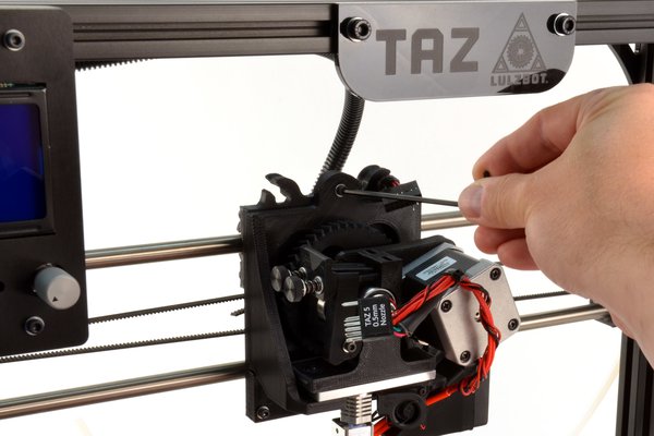
8A Use a 2.5 mm hex key to remove the screw in the bottom right of the tool head mount, as shown in image.
Note: Tool head mount does not need to be removed from the X-axis carriage, and is shown separately in the image for clarity.
8B Use a 2.5 mm hex key to replace screw with the M3x12 BHCS included with your V3 Dual tool head.

11A
Install the Dual Extruder Tool Head v3 by seating it on the X-axis carriage and securing it with the M3 screw that you removed in the previous step.
12A
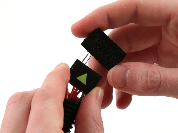
Remove the protective foam from harness.
12B
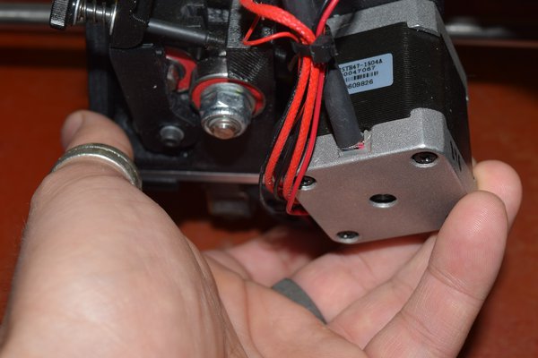
Connect the primary extruder harness (existing harness) to the right-hand (E2) connection on tool head, taking care to note polarity. Make sure to match connections based on the the pins in the connectors.
Note: Older models may have guide pins in the extruder harness for connecting with a standard tool head. If the pins are not aligning correctly with the Dual Extruder v3 connections, as shown in image, one of the pins may need to be removed. Refer to this Molex Pin Replacement guide, steps 3 and 4, for instructions on removing pins.
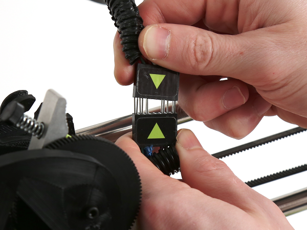
12C
Connect the secondary extruder harness (new harness) to the left-hand (E1) connection on tool head, taking care to note polarity. Make sure to match connections based on the the pins in the connectors.
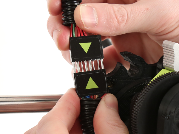
12D
Make sure the connectors are not against any moving parts and tuck into X-axis carriage notches.
Verify the connectors are appropriately connected before proceeding.

13A
Install the latest version of Cura LulzBot Edition. It is important to have the LulzBot Edition of Cura, as it has preset machine configuration profiles built into it.
13B
Cura LulzBot Edition is available from http://LulzBot.com/Cura.
13C
Plug in your LulzBot TAZ 3D Printer to the power supply and power on your 3D printer.
13D
Once powered on, connect your 3D printer to your computer using the USB cable.
13E
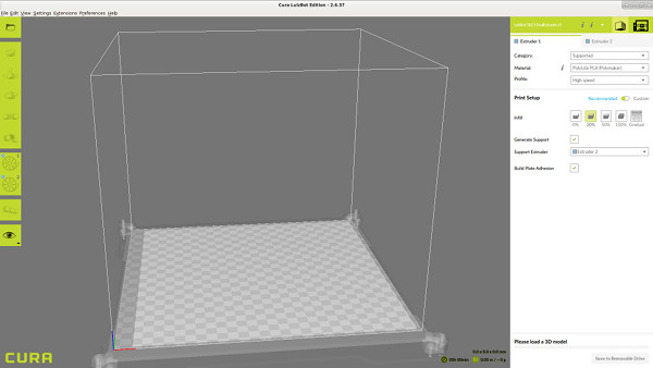
Open Cura LulzBot Edition.
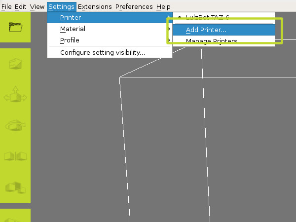
14A
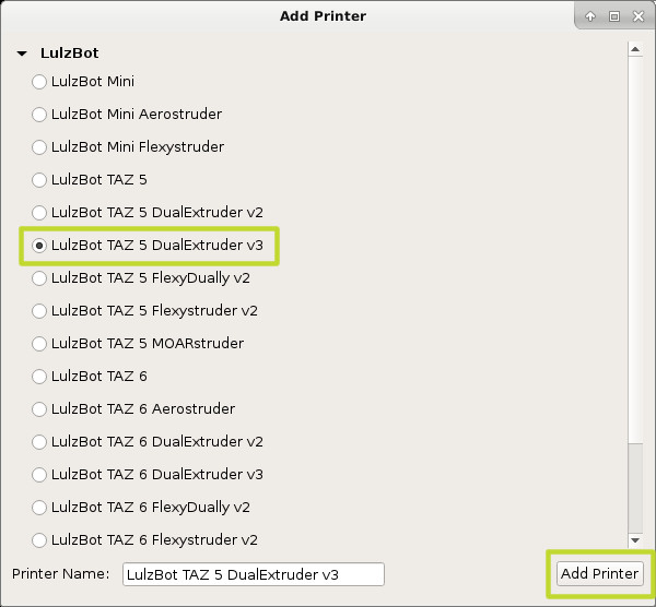
Select Settings dropdown > Printer > Add Printer.
14B
Select LulzBot TAZ 5 DualExtruder V3 and click Finish.

15A
Power on the printer.
15B
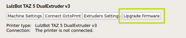
Select Settings dropdown > Printer > Manage Printers.
15C
Confirm the LulzBot TAZ 5 DualExtruder v3 is selected, and click Upgrade Firmware.
NOTE: Follow the instructions displayed on screen and [linked here] to record and restore your Z-axis offset.
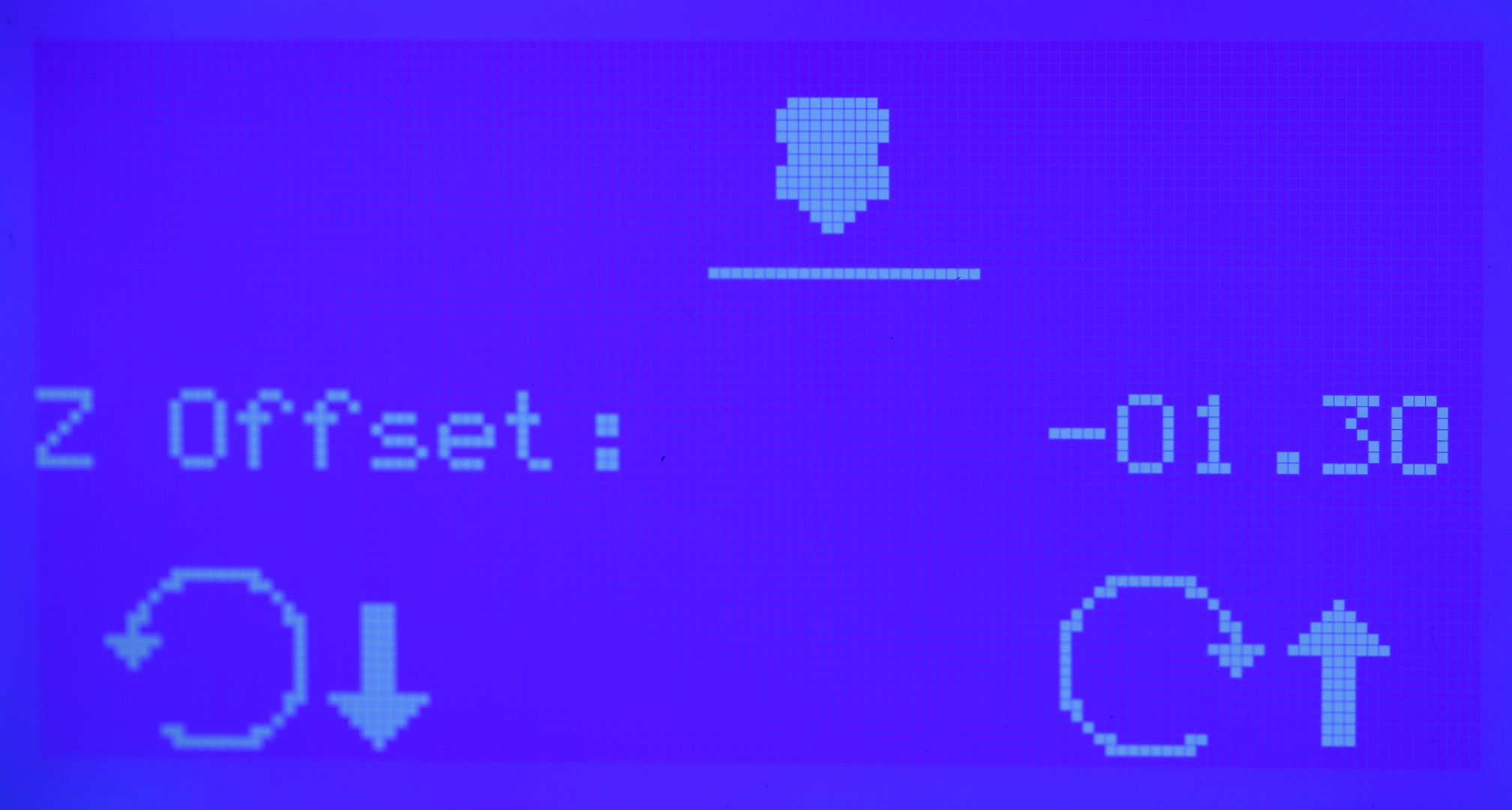
16A
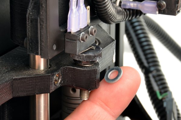
To prevent damage to your 3D printer, power it off immediately if the tool head looks like it is on a course to lower into the print surface before triggering the Z end stop.
If the tool head looks like it will prematurely trigger the Z end stop too high above the print bed, adjust the thumb screw lower and restart this process.
The spring and washer can be removed if needed to achieve the proper Z height.
17A
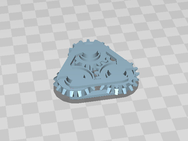
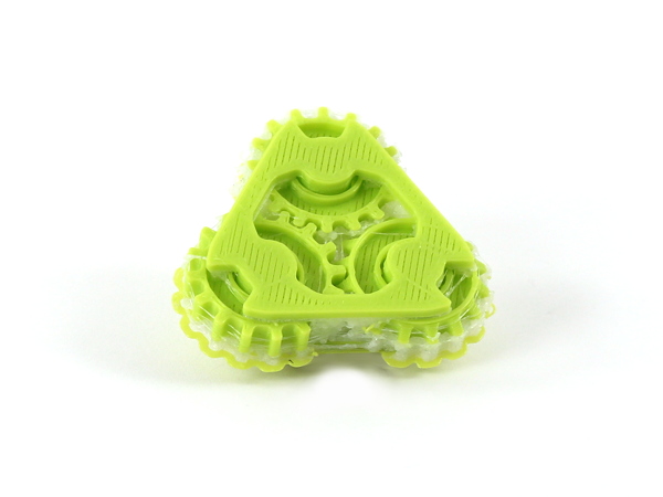
Download the recommended first print: Impossible Gear and load it into Cura.
17B
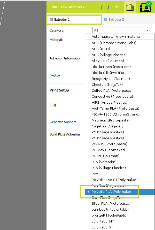
Adjust the default print settings to match the first print materials: Polylite PLA and PolyDissolve S1 by following steps below:
17C
Confirm selections for Extruder 1: Extruder 1 tab > Material drop down, select Polylite PLA > Profile, select Standard Quality .
17D
Select Extruder 2 tab > Material drop down: PolyDissolve S1
17E
Click the Generate Support box in the Print Setup area, and verify that Hot End 2 is selected to activate the support material.

18A
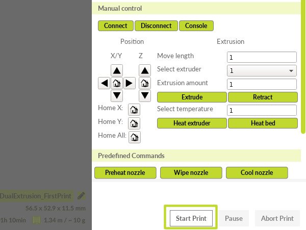
In the top of the Cura LE window, click the Print Monitor tab, as shown in the image. Steps 18 and 19 are implemented through this tab's settings.

19A
Check that Cura LulzBot Edition shows USB devices detected then click on the Connect button.
19B
Wait for message to show Connected via USB.

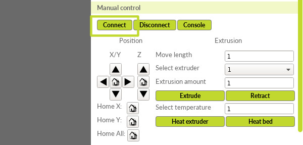

20A
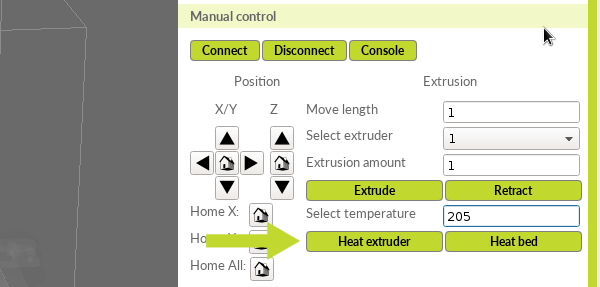
Confirm Extruder 1 is selected in the Select extruder drop down menu, as shown in the image.
20B
Insert temperature as 205°C.
20C
Select Heat Extruder.
20D
Select Extruder 2.
20E
Insert temperature as 220°C.
20F
Select Heat extruder.
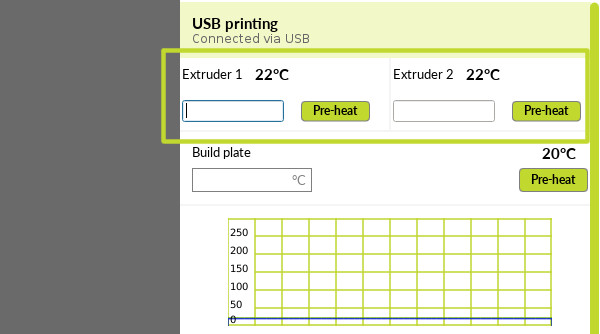
Note: If you scroll down, another option is available to assign to temperature values to each extruder, as shown in image. Enter in the same value for each each extruder as shown above, then select Heat extruder.
21A
Once extruders reach temperature, remove test filament used during factory calibration.
Note: To remove filament, wind gear counterclockwise for Extruder 1, and clockwise for Extruder 2. OR, you can also squeeze idler inwards, and pull filament out.
22A
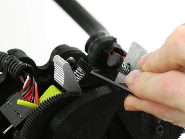
To prevent the filament from stripping, it's important to calibrate both of the idlers before loading in the new filament.
22B
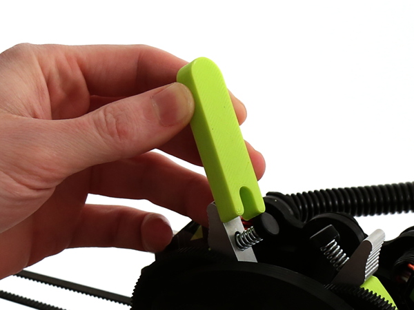
Locate the printed idler jig included with your LulzBot TAZ Dual Extruder v3 Tool Head.
Note: Idler jig is colored black in the kit, but is shown here in green for clarity and ease of visibility.
22C
Insert printed idler jig next to an idler, as shown in the image.
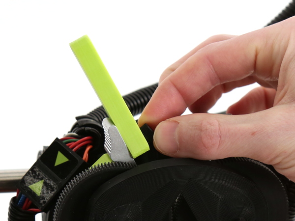
22D
Adjust each idler onto the printed jig one at a time. They should be tightened until the black head of the idler makes contact with the jig. Do not overtighten. The printed jig should be able to slide out easily.

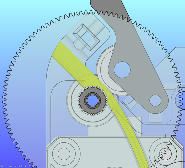
23A
In order to keep the Dual Extruder v3 as compact as possible, the filament path was designed differently than on Standard LulzBot Tool Heads. Steps for inserting filament are further detailed below:
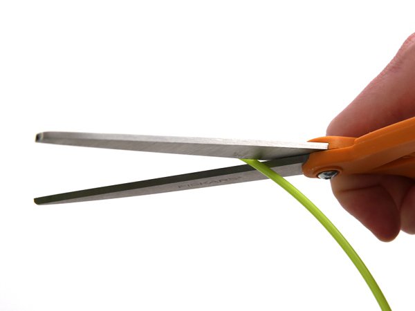
24A
Clip end of filament with scissors to form a slanted point. This will improve the insertion effectiveness of the filament as it reaches the channel.
24B
Load Polylite PLA in Extruder 1 (left), and PolyDissolve S1 in Extruder 2 (right). Slightly pull back on the idler arm and insert the filament from a 45° angle.
24C
Once the filament stops, you may need to wiggle the filament until it slides in farther.
24D
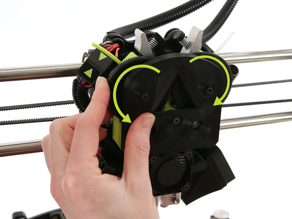
Rotate the gears by hand to help pull the filament into the tool head. Clockwise for Extruder 1, counterclockwise for Extruder 2.
Note: If you're still experiencing difficulty loading the filament, slightly loosen the idler tension by half-turn increments to allow for more space on the filament path. It's possible for the filament to emerge from the back of the extruder during loading, simply remove and try loading again. Make sure the filament end is clipped at an angle to reach the channel.
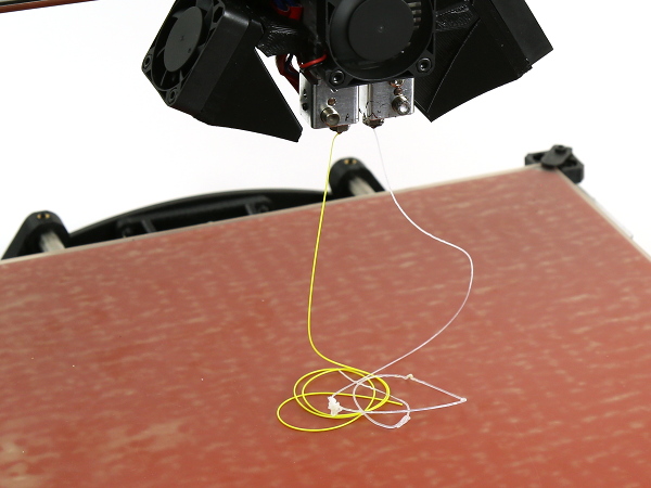
24E
Purge factory filament by continuing to rotate gears by hand for both extruders, until extrusion transitions into the sample filament. Clockwise for Extruder 1, counterclockwise for Extruder 2.


25A
Click the Start button.
26A
Wait until bed cools to recommended part removal temperature.
26B
Use blue handle knife to lift print off of bed.
27A
We recommend placing the print in water and letting it sit to allow the soluble support filament to loosen and come off naturally. Change water and rinse the printed object every hour or two, depending on the size of the print.
Optional: Structural support may soften after 30 minutes and can be removed using additional tools, such as a tweezer or dentist pick. If not soft enough, print will need to be agitated and water refreshed regularly to further dissolve filament.
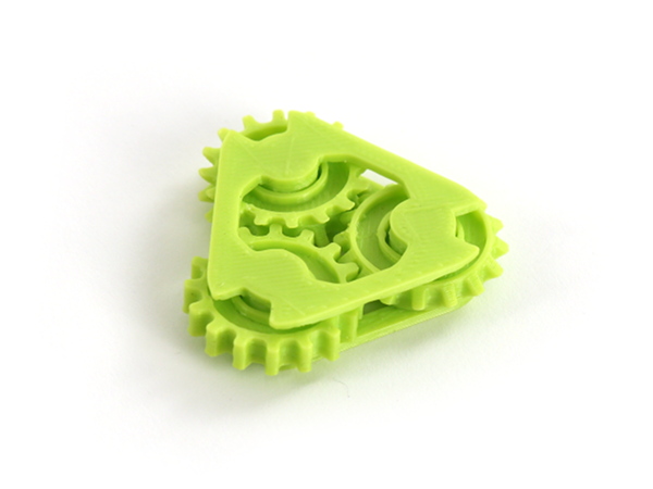
You've now finished installation and are ready to explore new territories of 3D printing with your Dual Extruder v3!