Open HardwareAssembly Instructions
Guides for installation and assembly of the LulzBot line of products made by FAME 3D LLC.
Guides for installation and assembly of the LulzBot line of products made by FAME 3D LLC.
Components
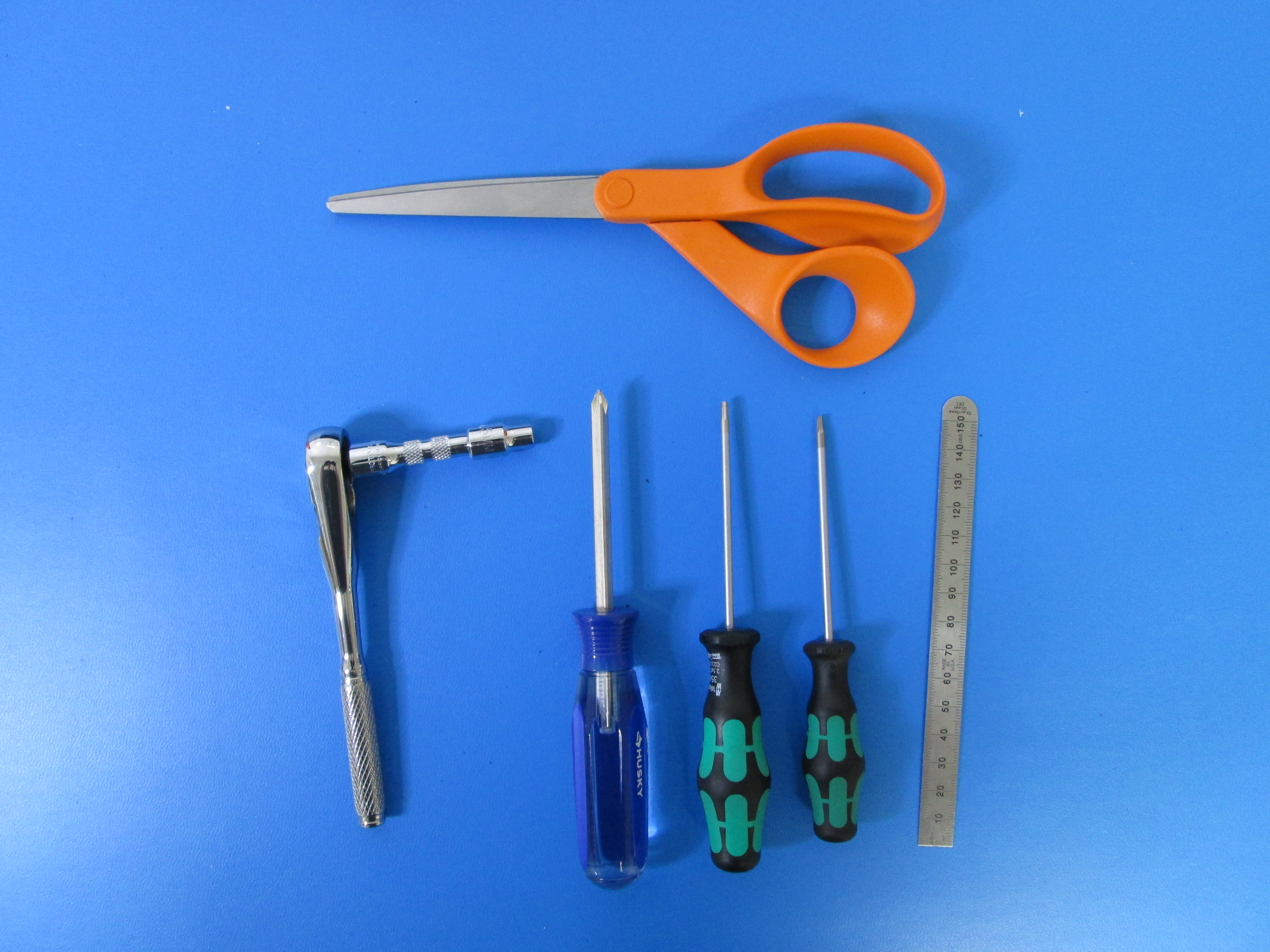
Tools

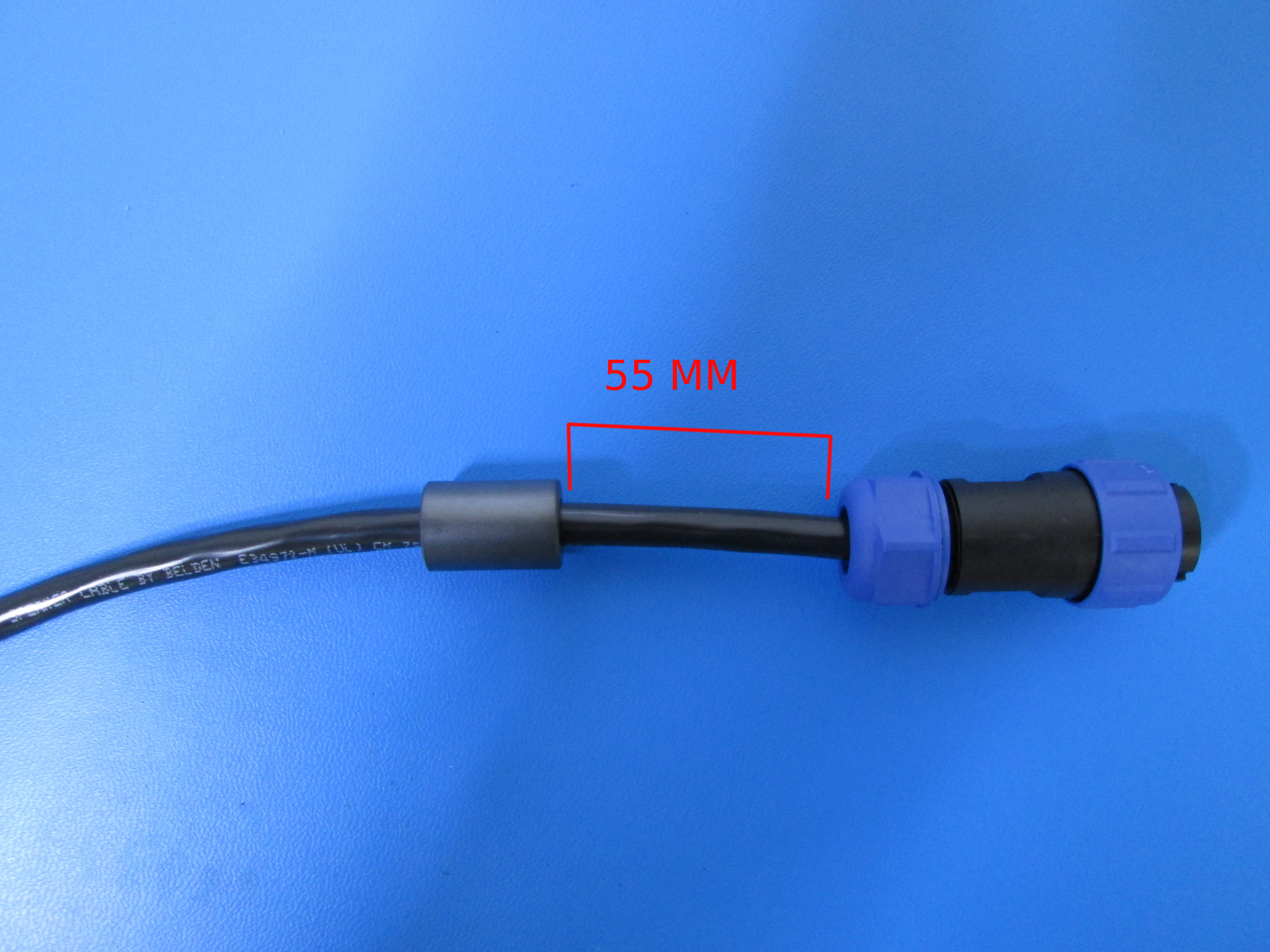
Install the ferrite by sliding it onto the power cable as shown.
The ferrite should be ~55 mm from the end of the connector as shown.
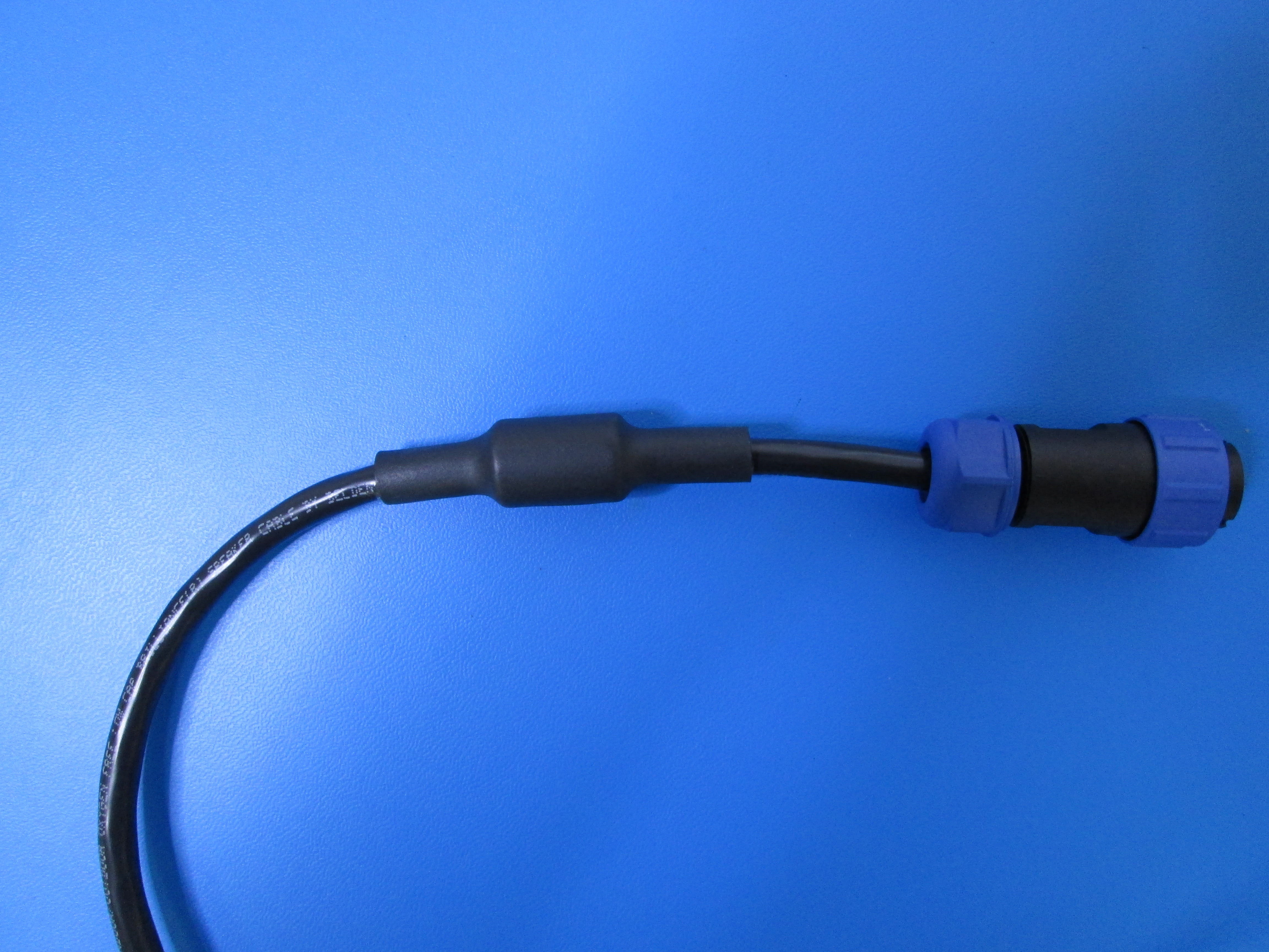
Slide a piece of 3/4" heat shrink over the cable and over the ferrite, centering the heat shrink over the ferrite.
Heat the shrink wrap with a heat gun, making sure the heat shrink stays centered over the ferrite.
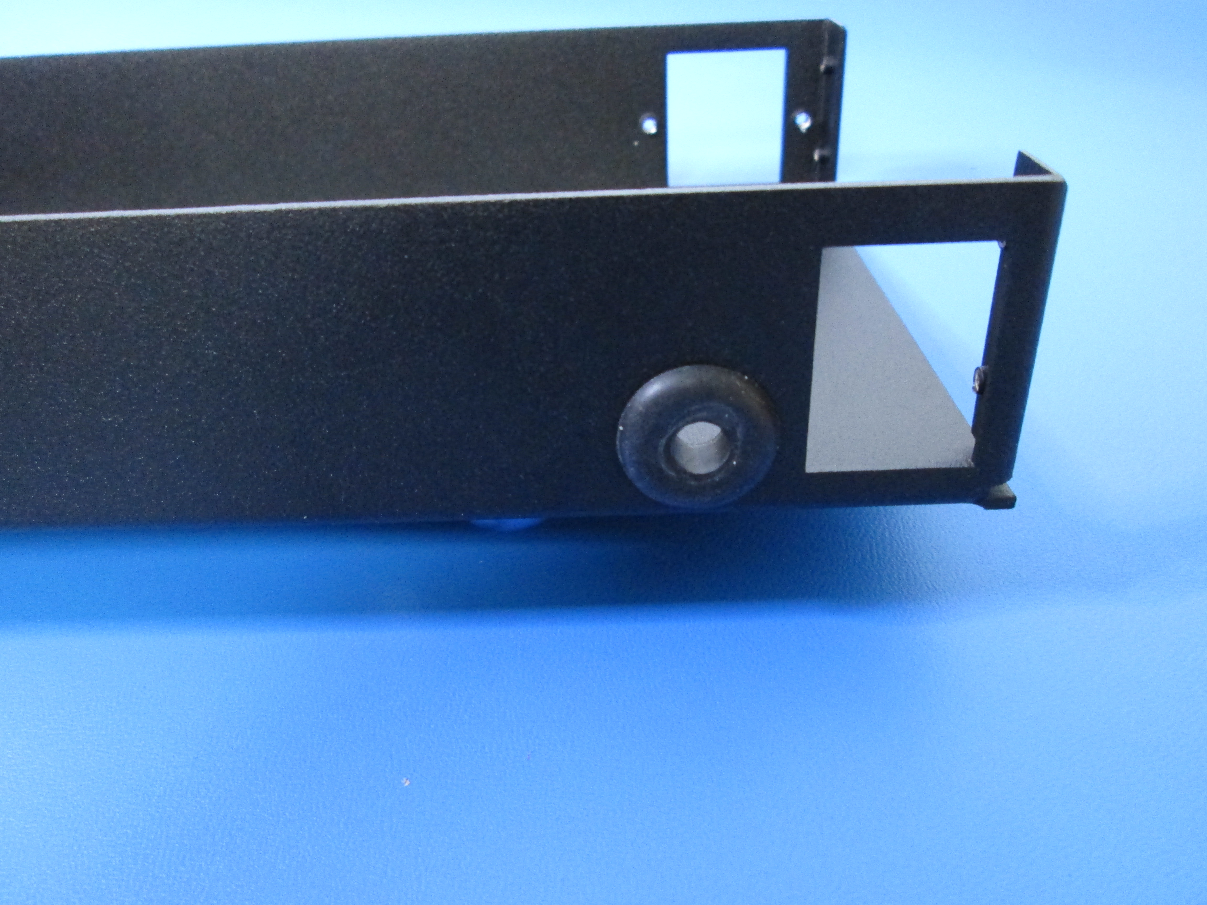
Install the rubber grommet as shown.
Install the power cable through the rubber grommet one end at a time to ensure it fits through the grommet as shown. You may have to hold the rubber grommet in place while you slide the cable through.
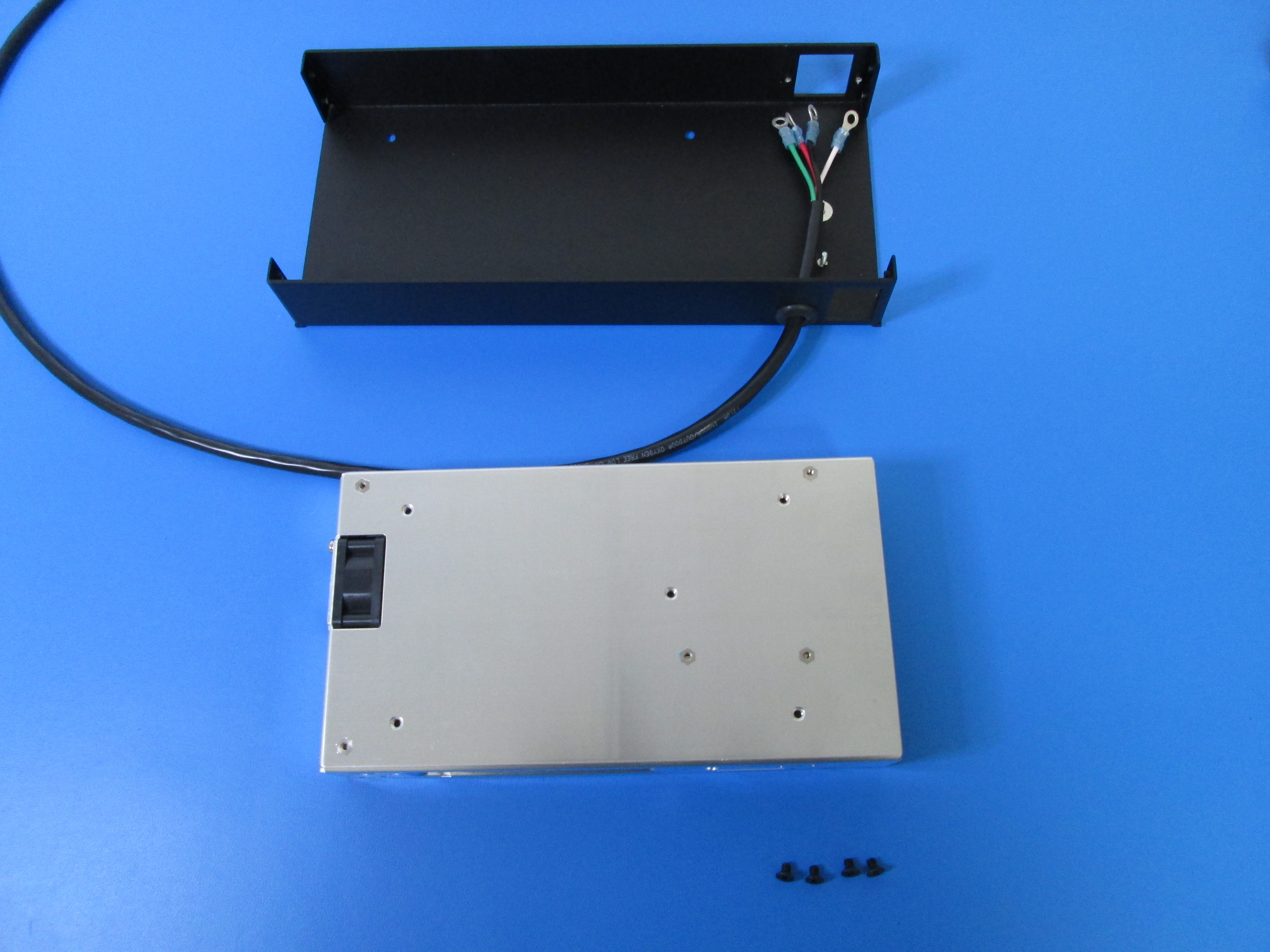
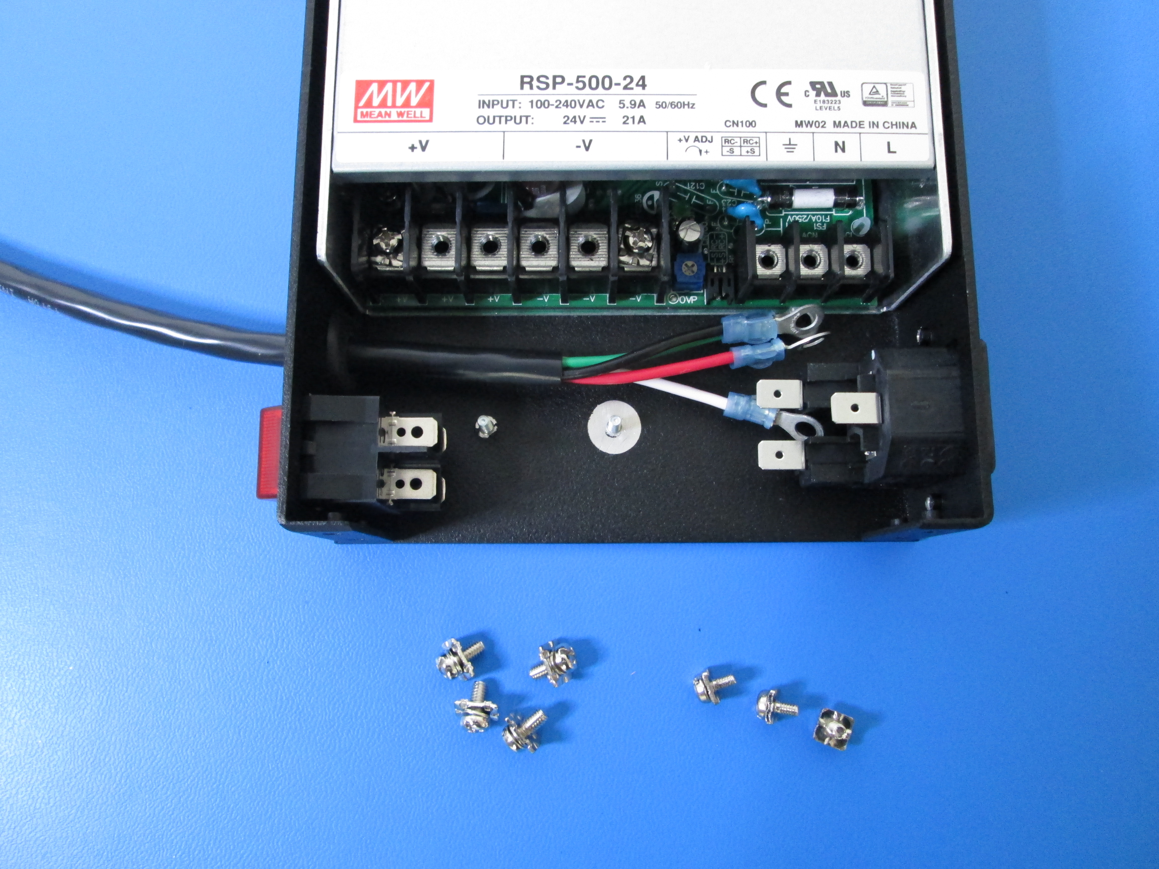
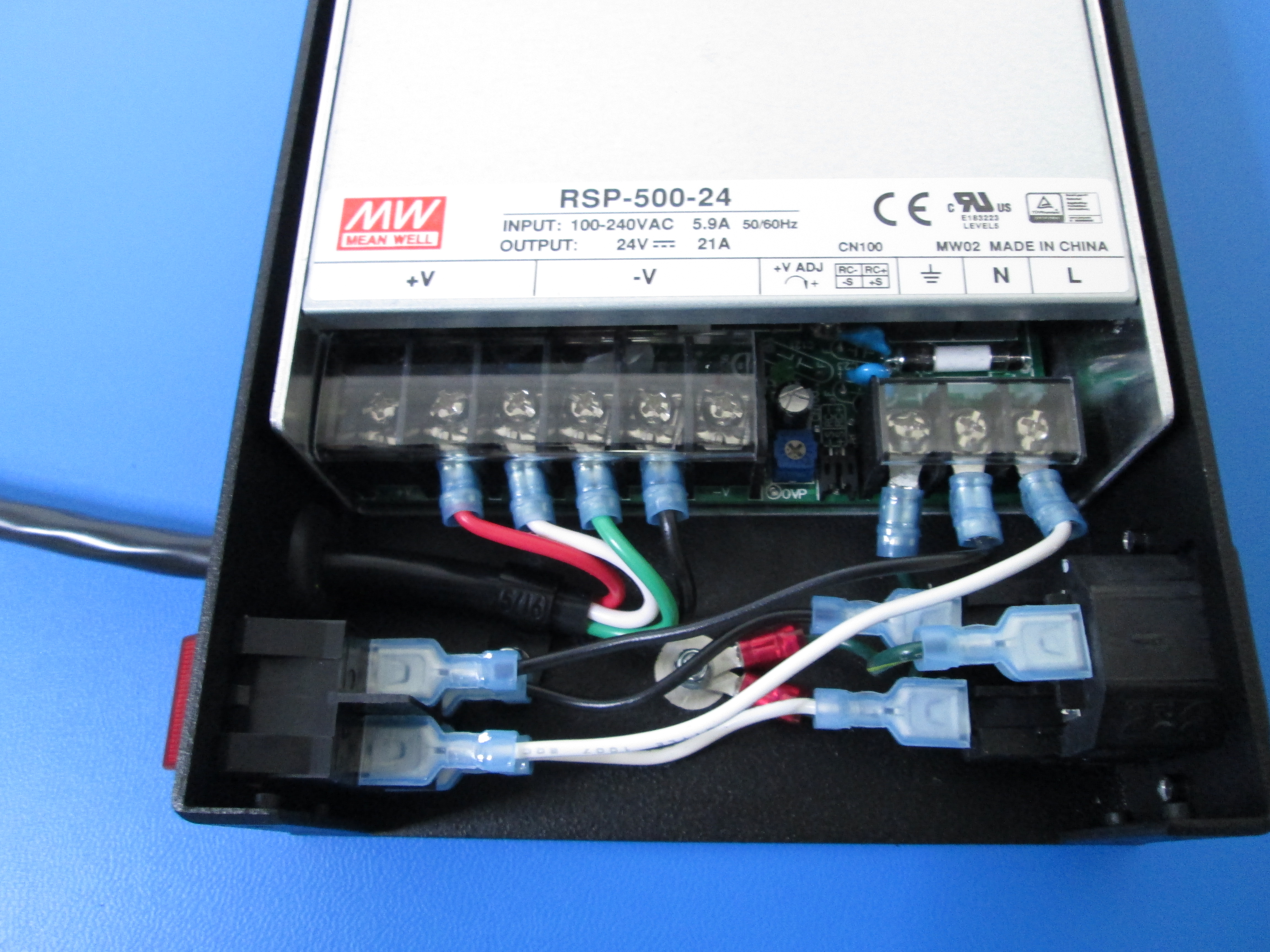
Install the Power Supply Unit using 4x M4x6 flat head screws as shown. Note orientation of the power supply.

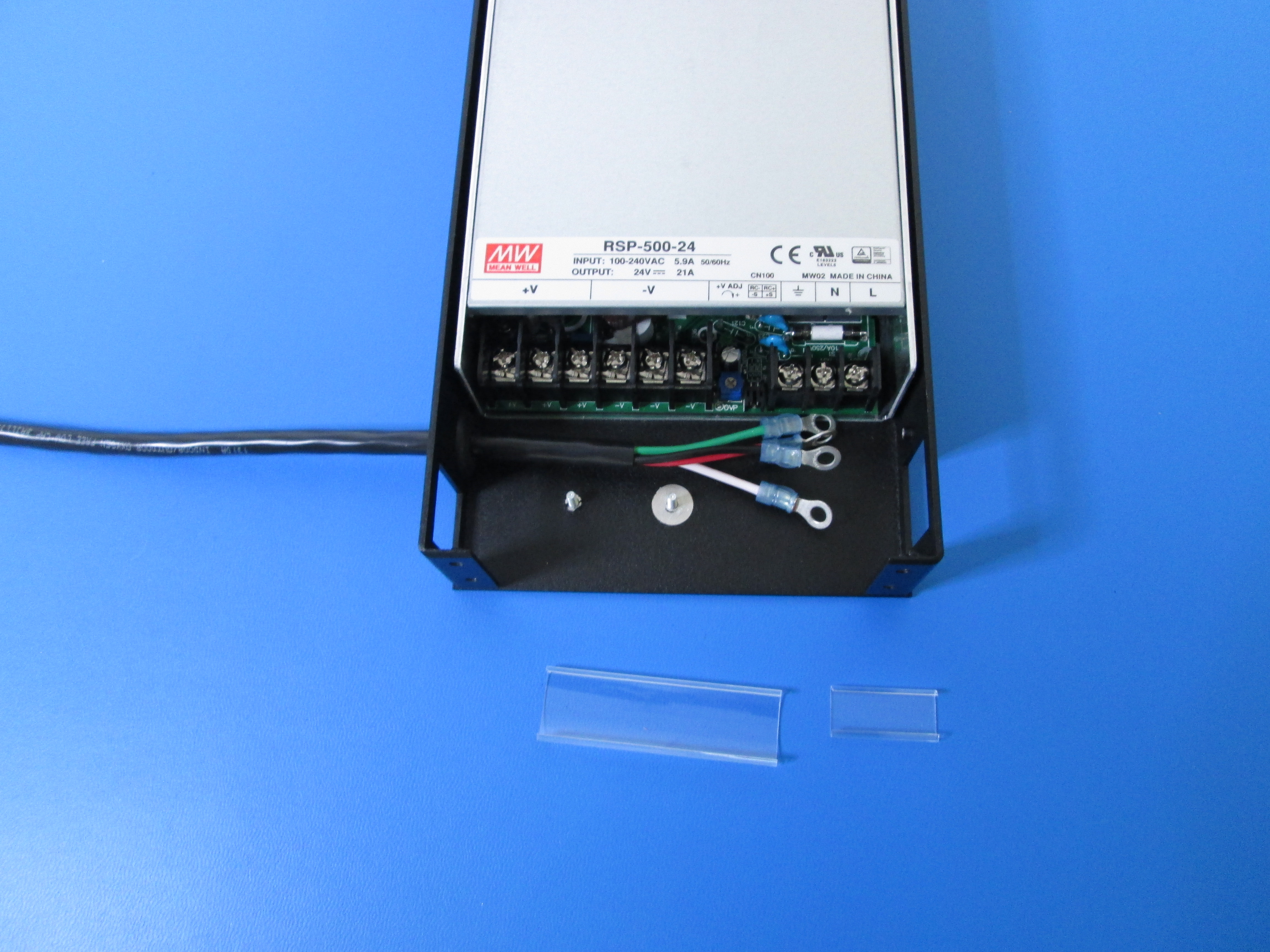
Remove the 2x plastic terminal covers and set them aside. You will need them later.
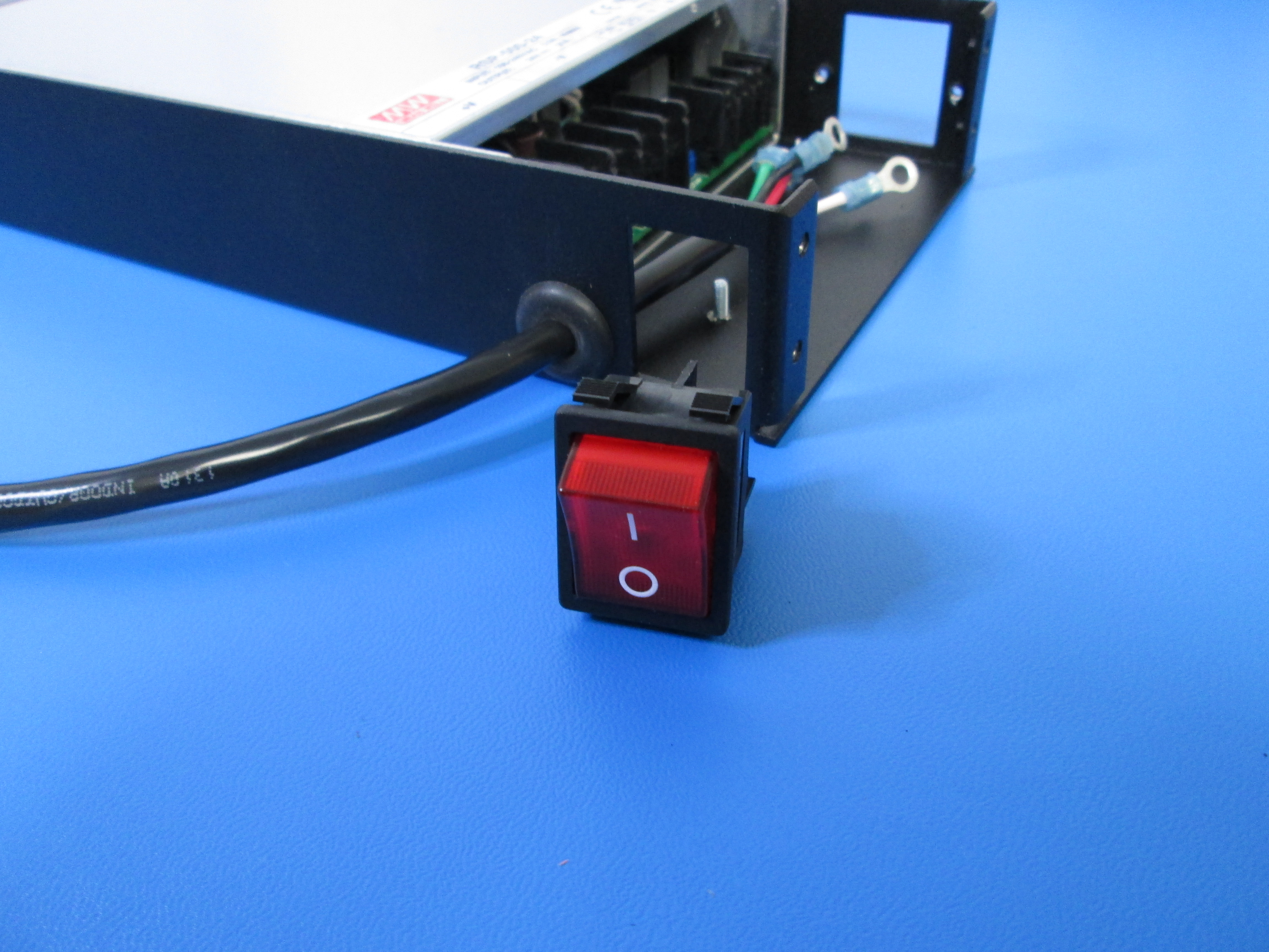
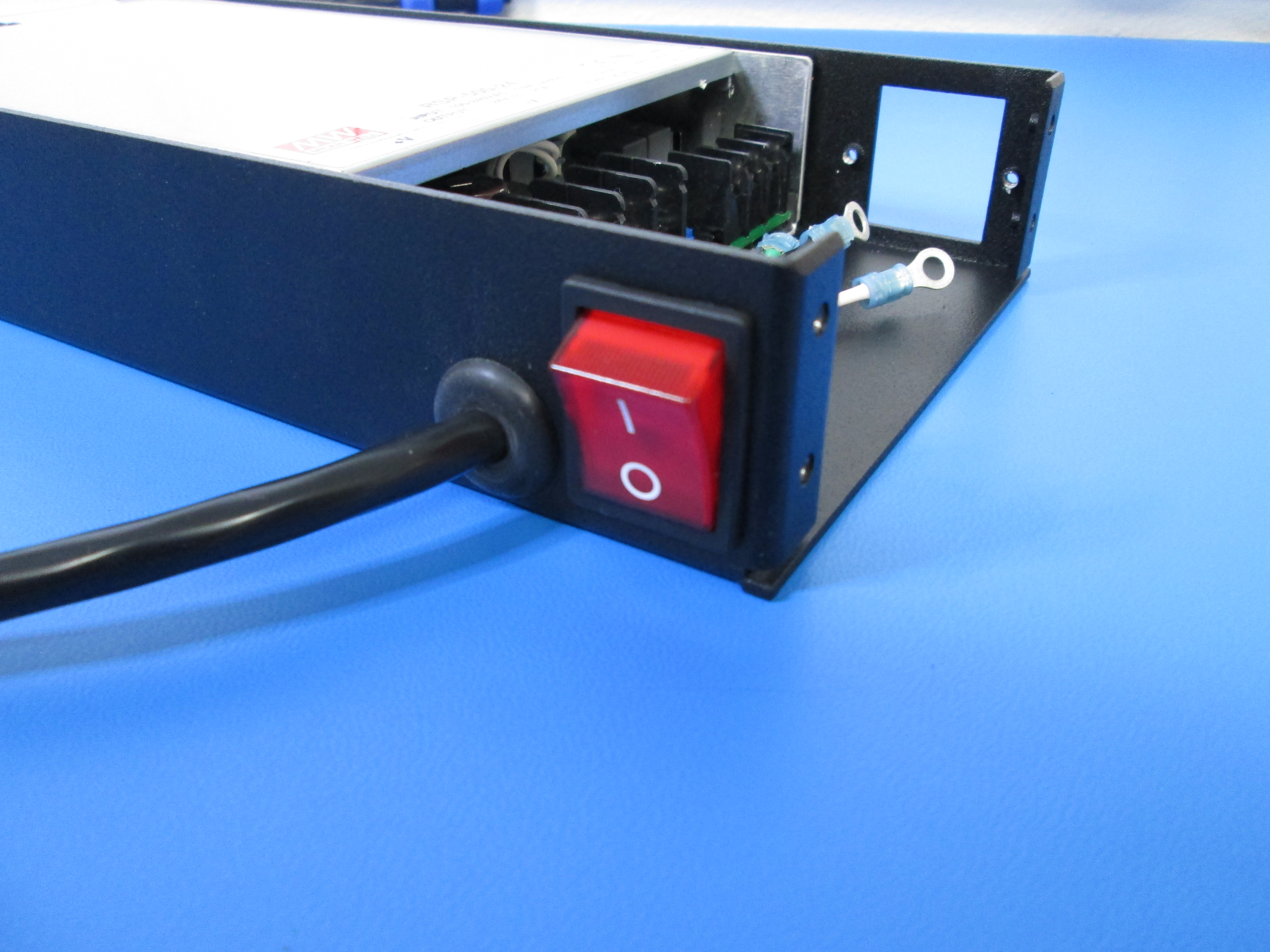
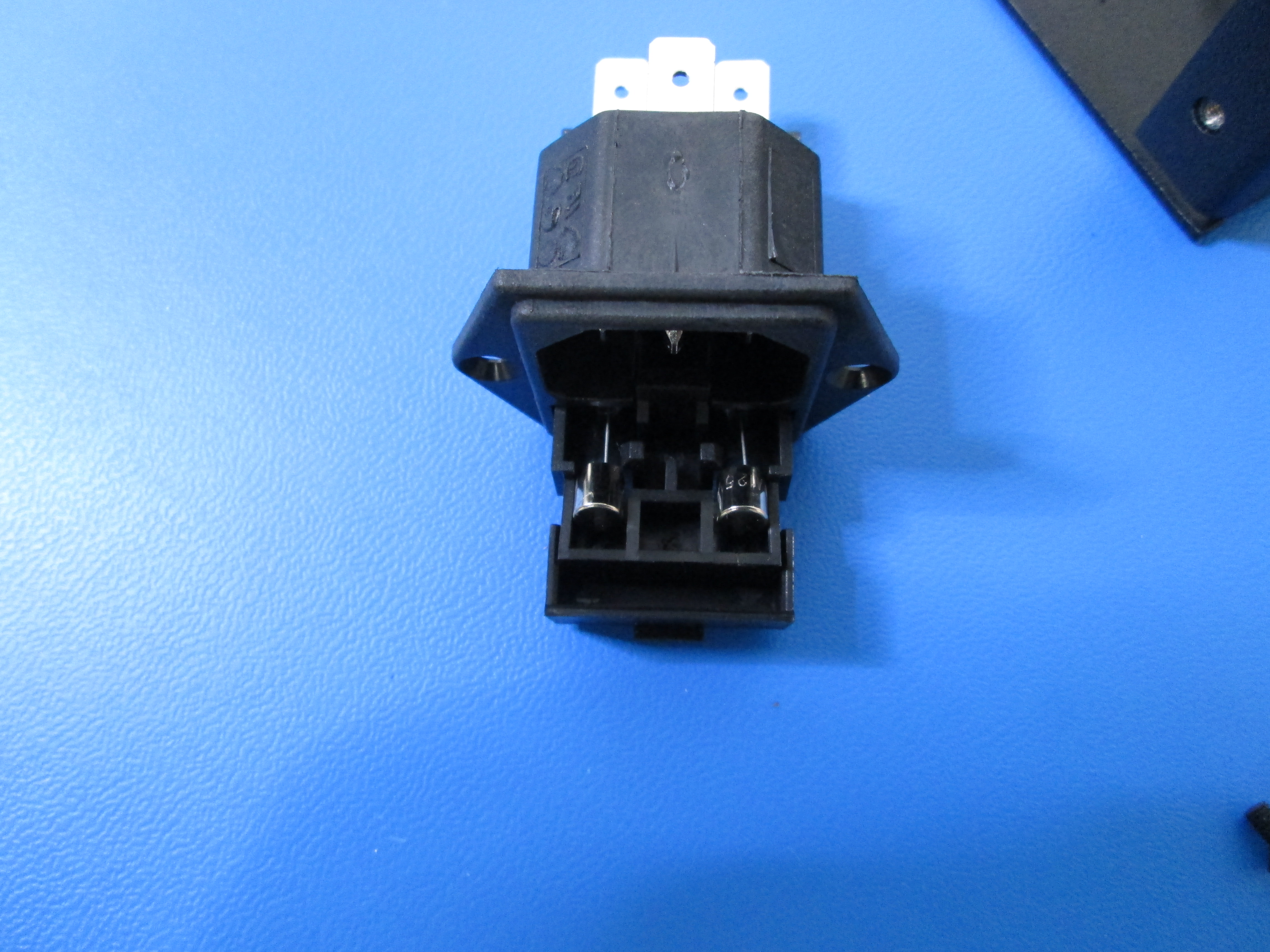
Install the Power Switch as shown. Make sure it is oriented correctly with the "O" towards the bottom as shown.
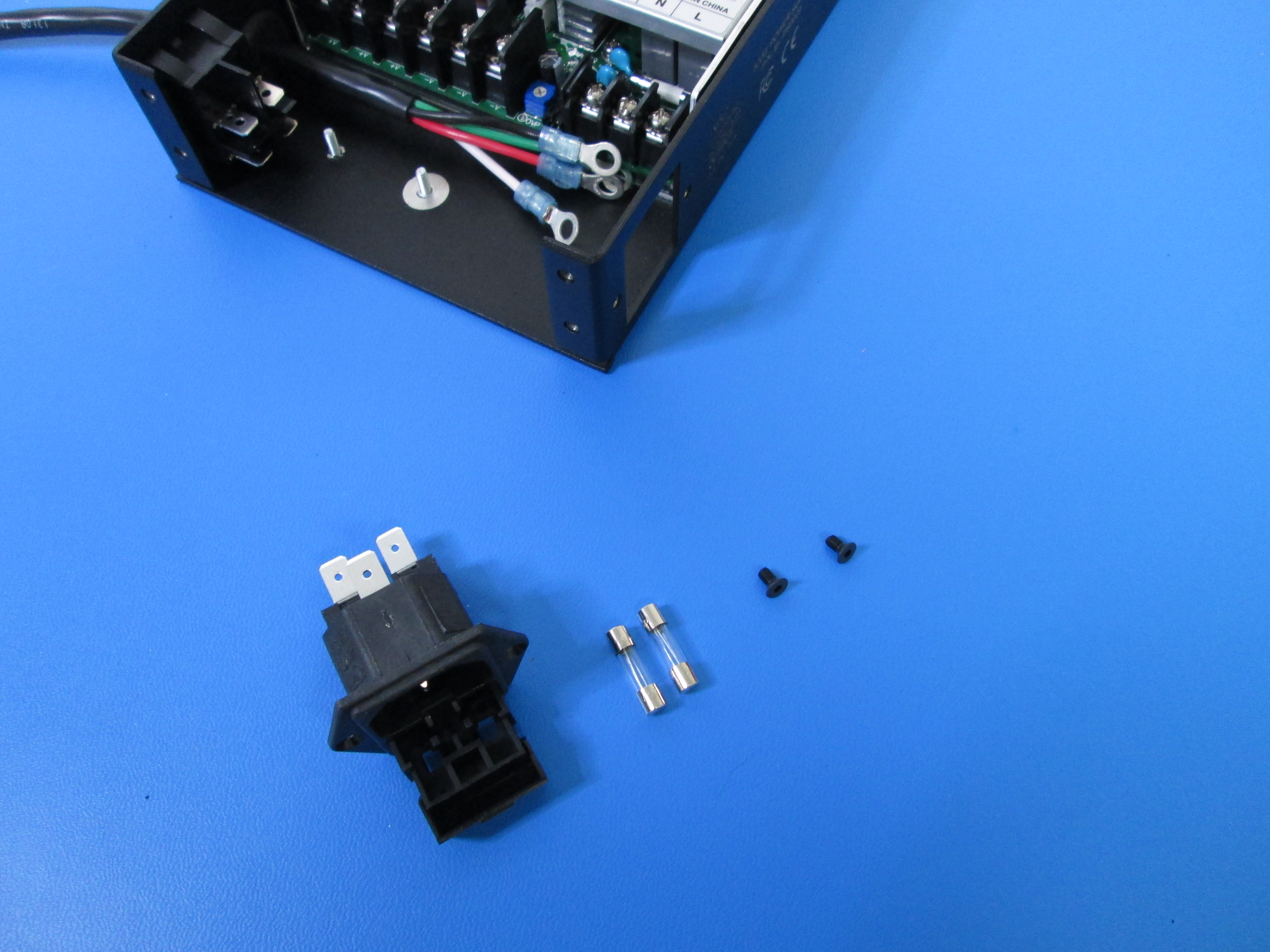
Install 2x 125V Fuses into the Power Receptacle as shown.
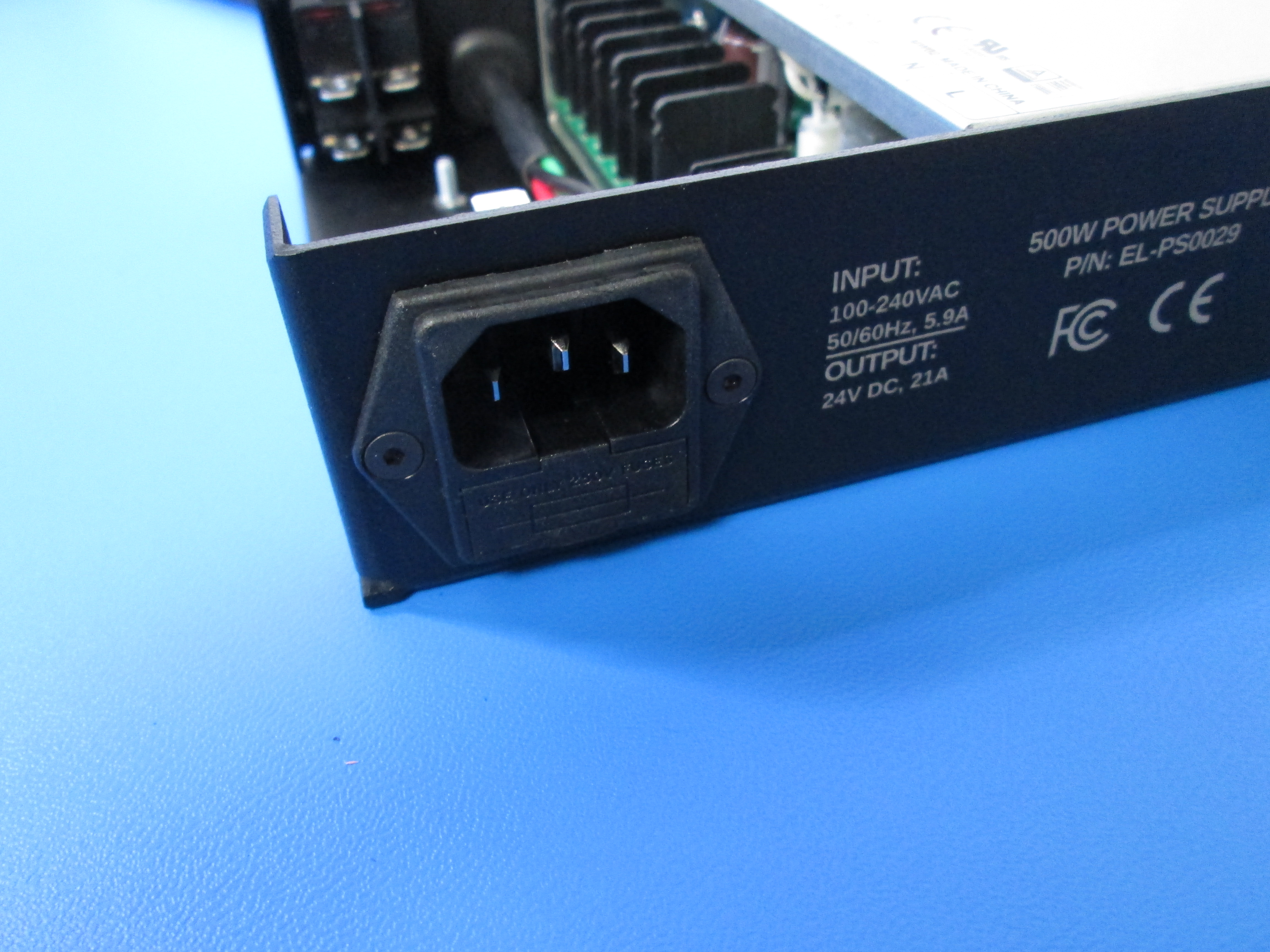
Install the Power Receptacle using 2x M3x6 flat head screws as shown, note orientation.
Remove the 4 middle screws from the left terminal block and the 3 from the right terminal block as shown. The 2 terminal blocks have different size screws so keep track of that.
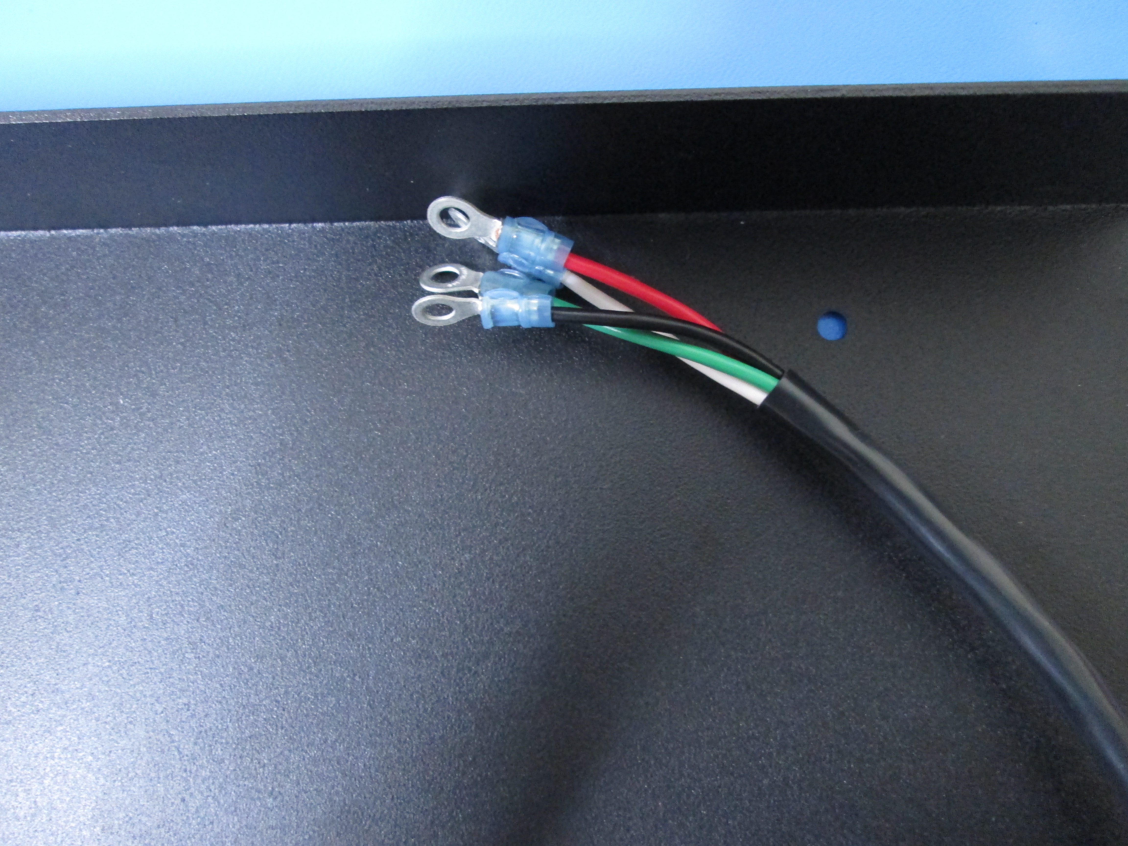
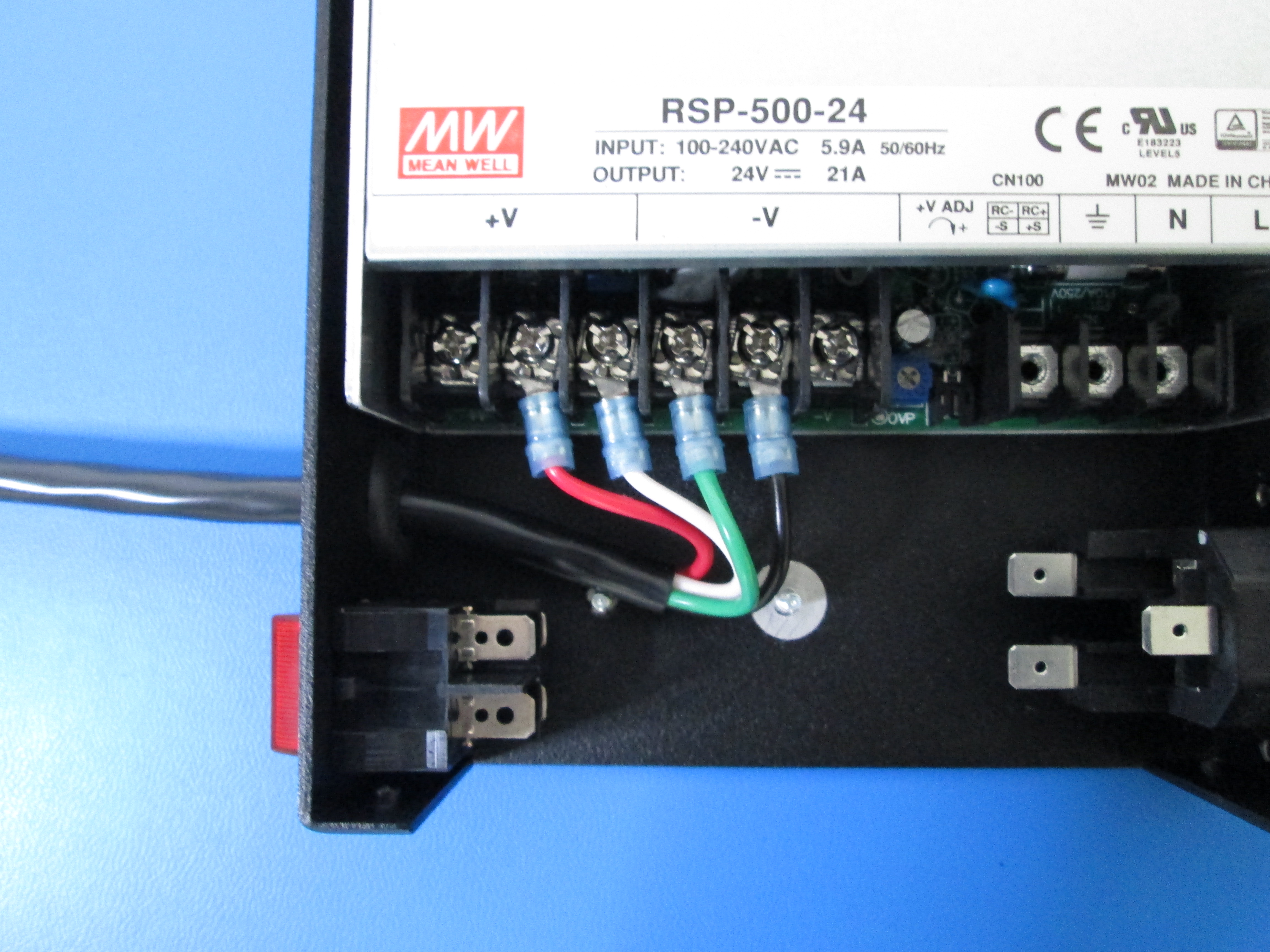
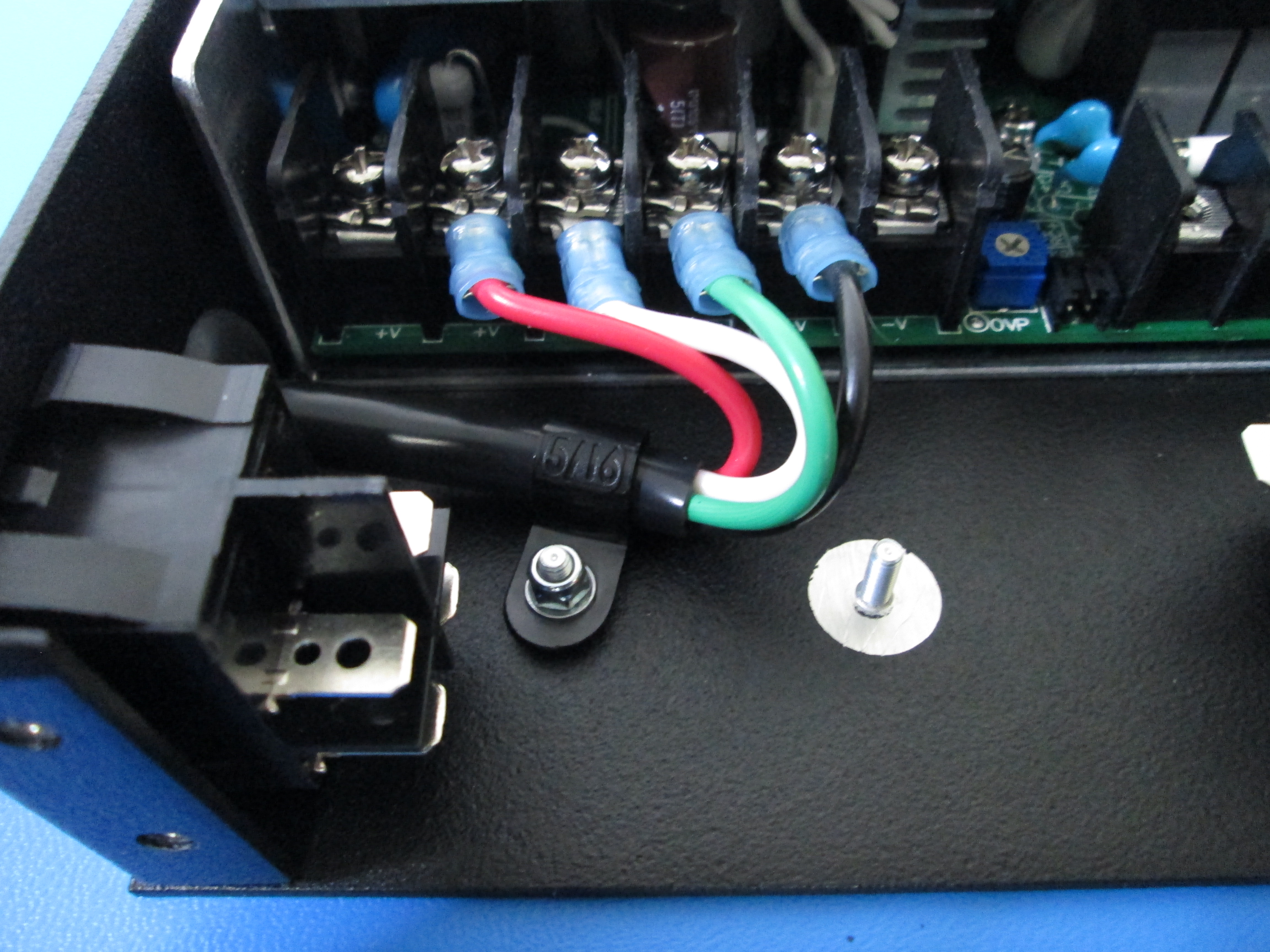
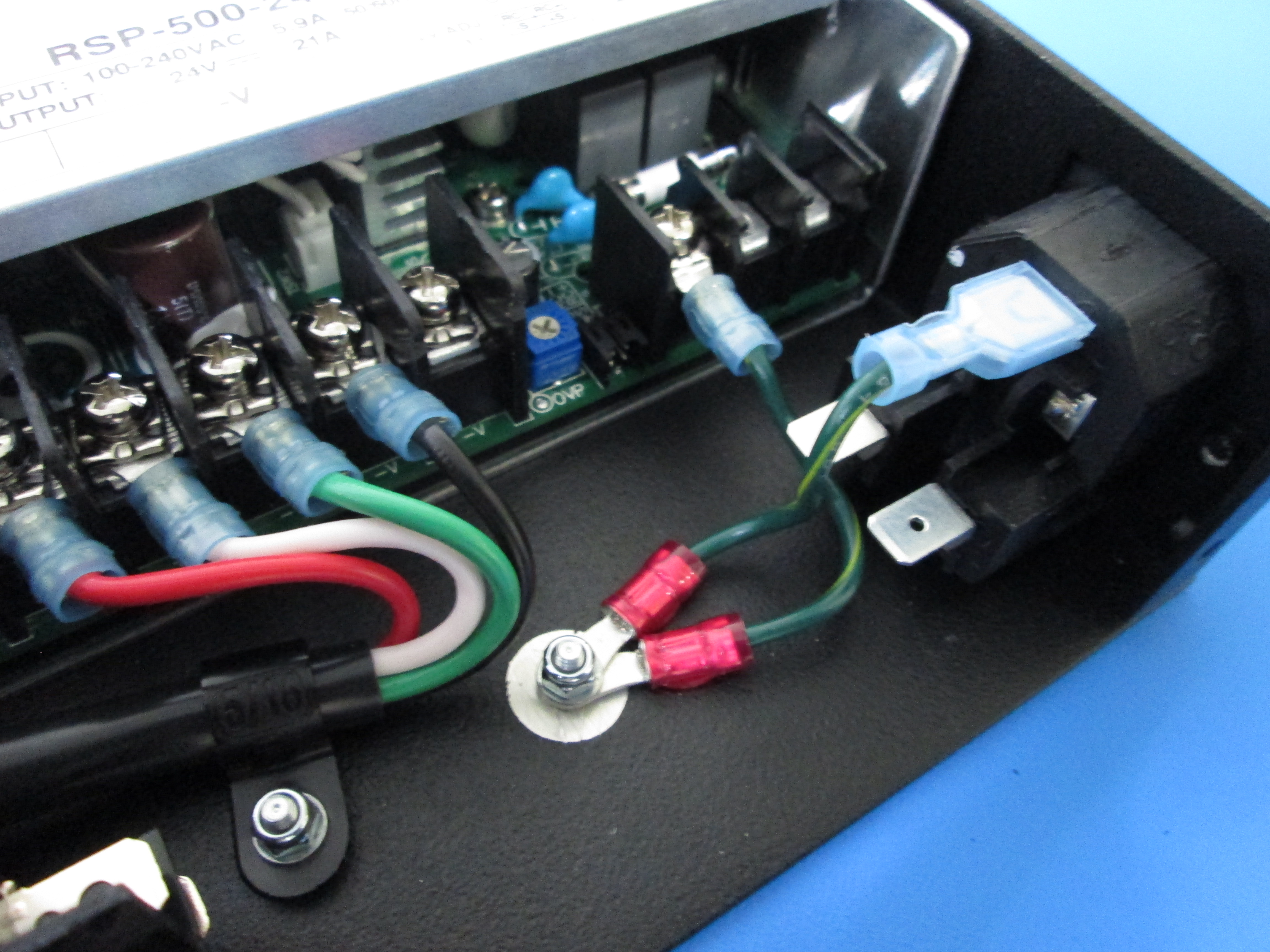
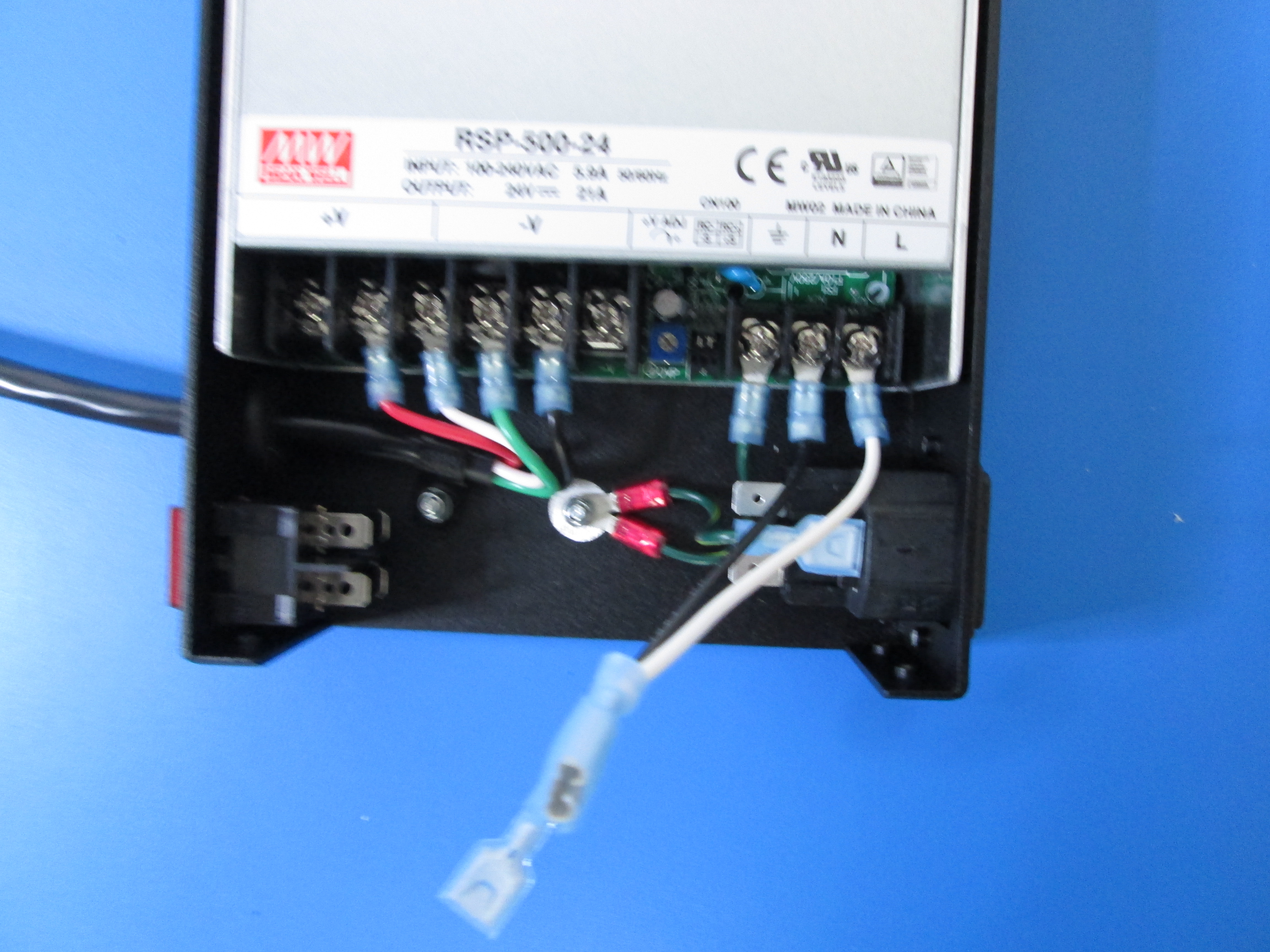
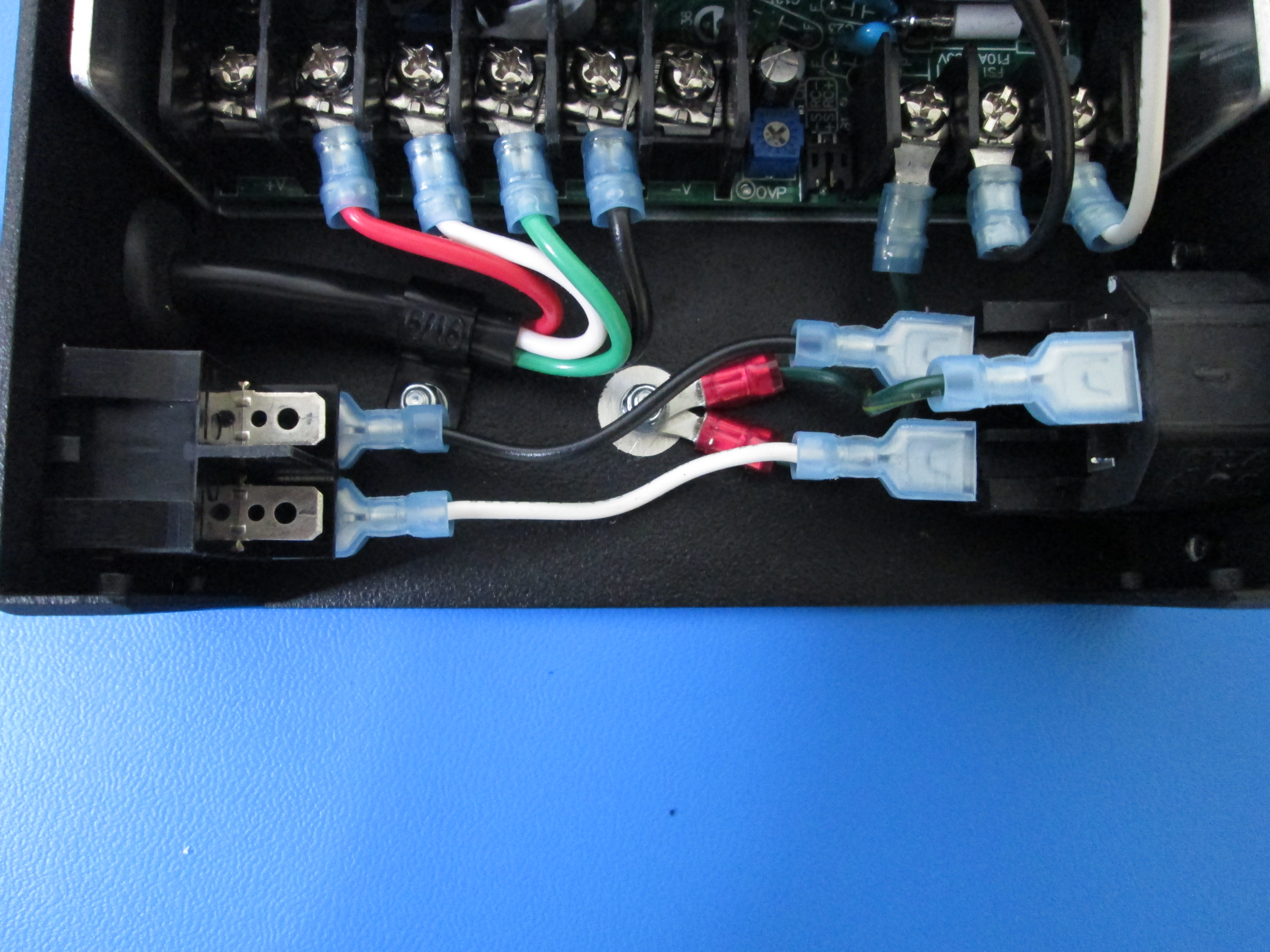
Hook up the power cable to the left terminal block using the screws you just removed as shown making sure the wires go to the correct terminals as shown. From left to right it will go Red, White, Green the Black.
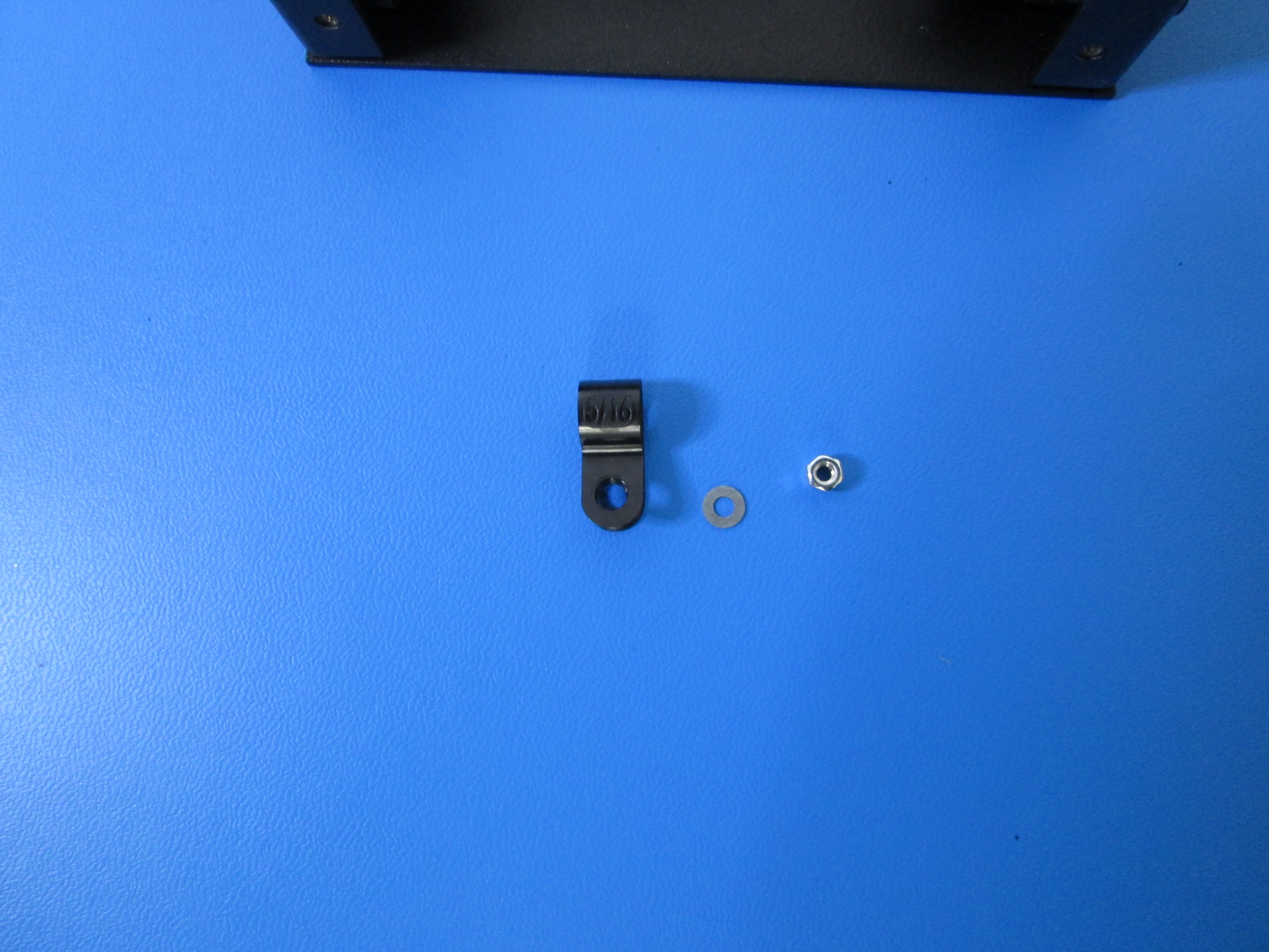
Next, use the nylon loop clamp to fasten down the cable using a M3 washer and an M3 Nyloc nut as shown.
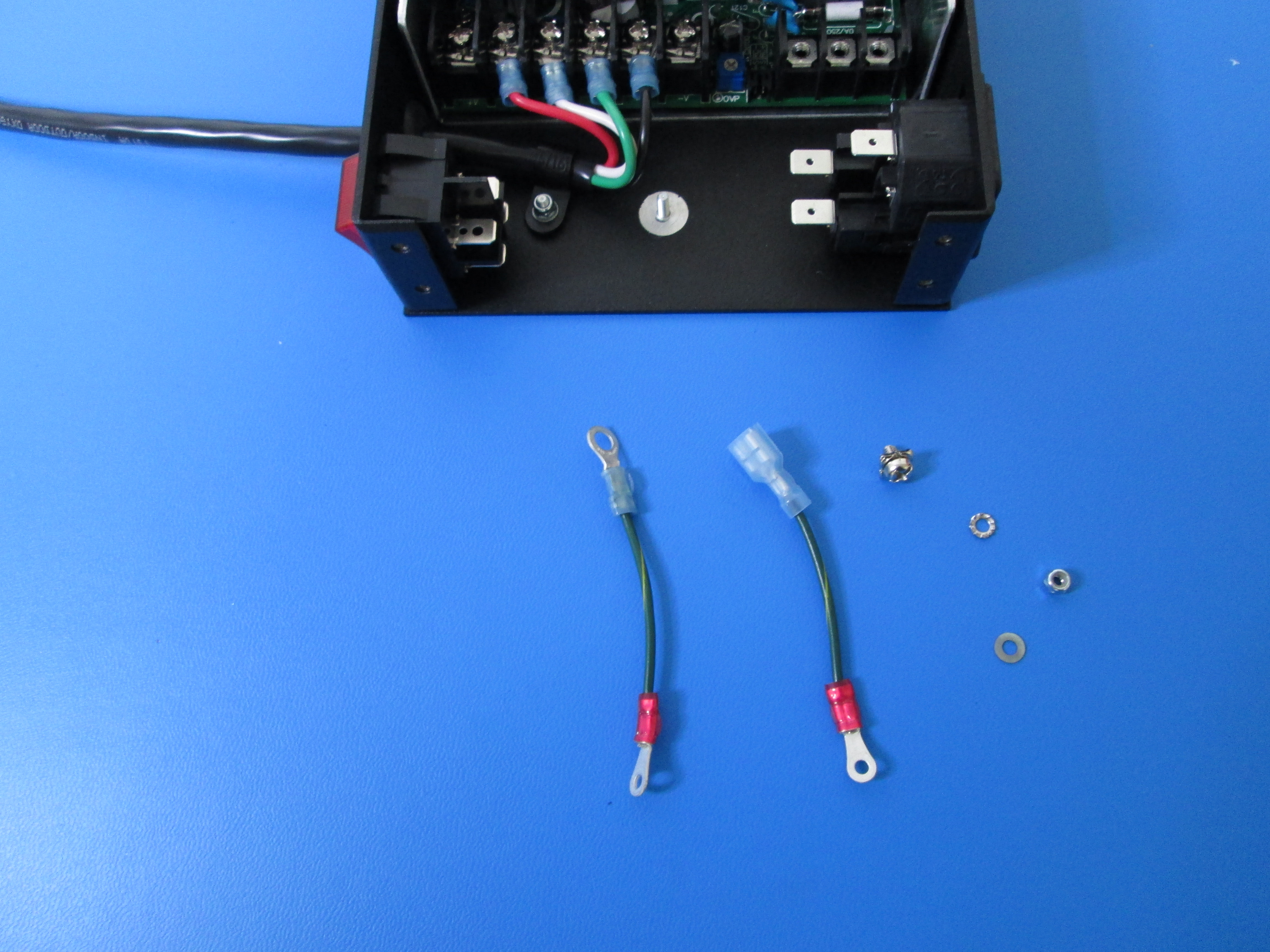
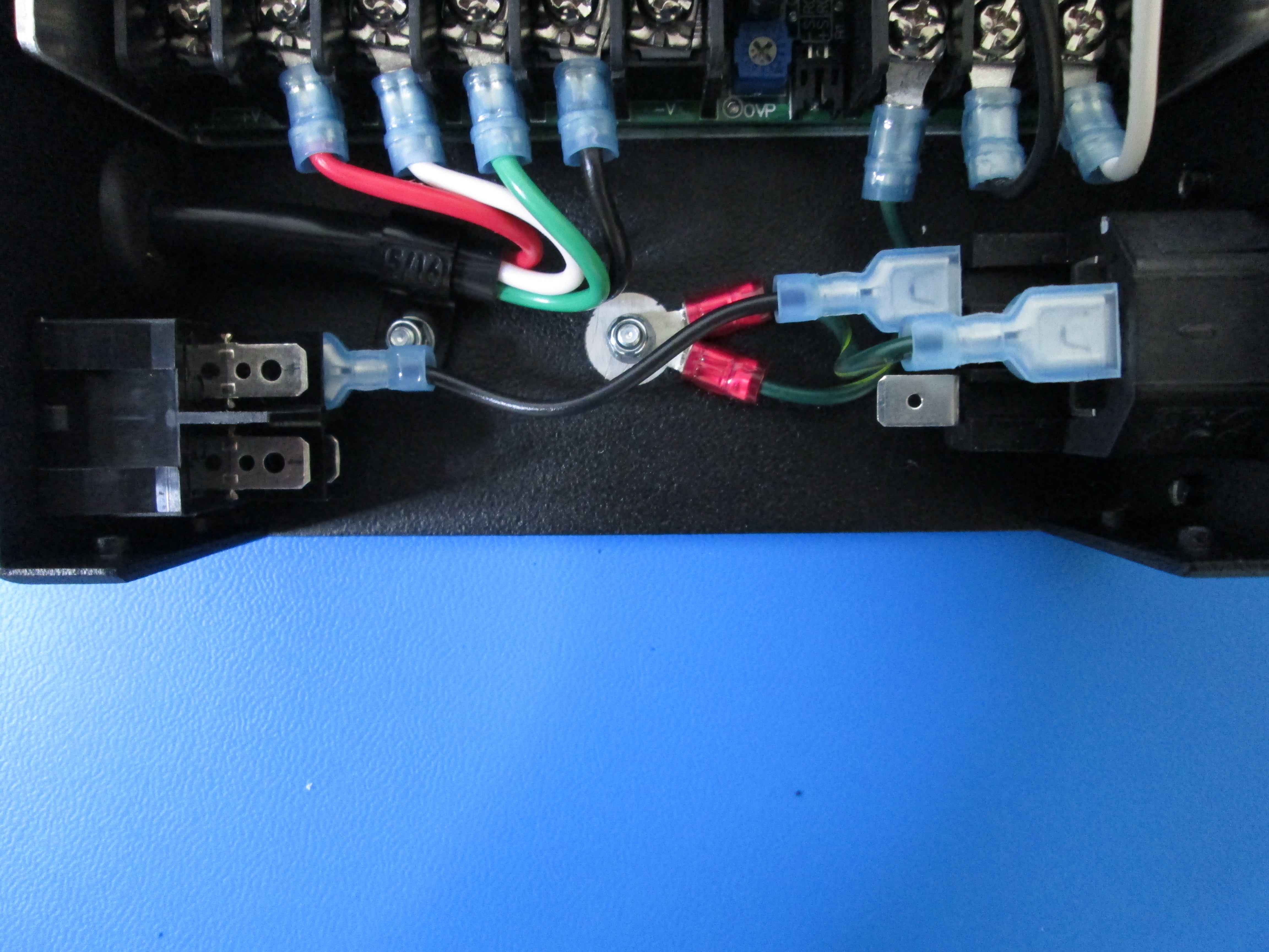
Install the 60mm green ground wire with the 2 terminal rings. The Blue terminal ring will go to the first terminal on the right terminal block as shown.
Attach the other 60mm green ground wire to the top spade of the receptacle as shown.
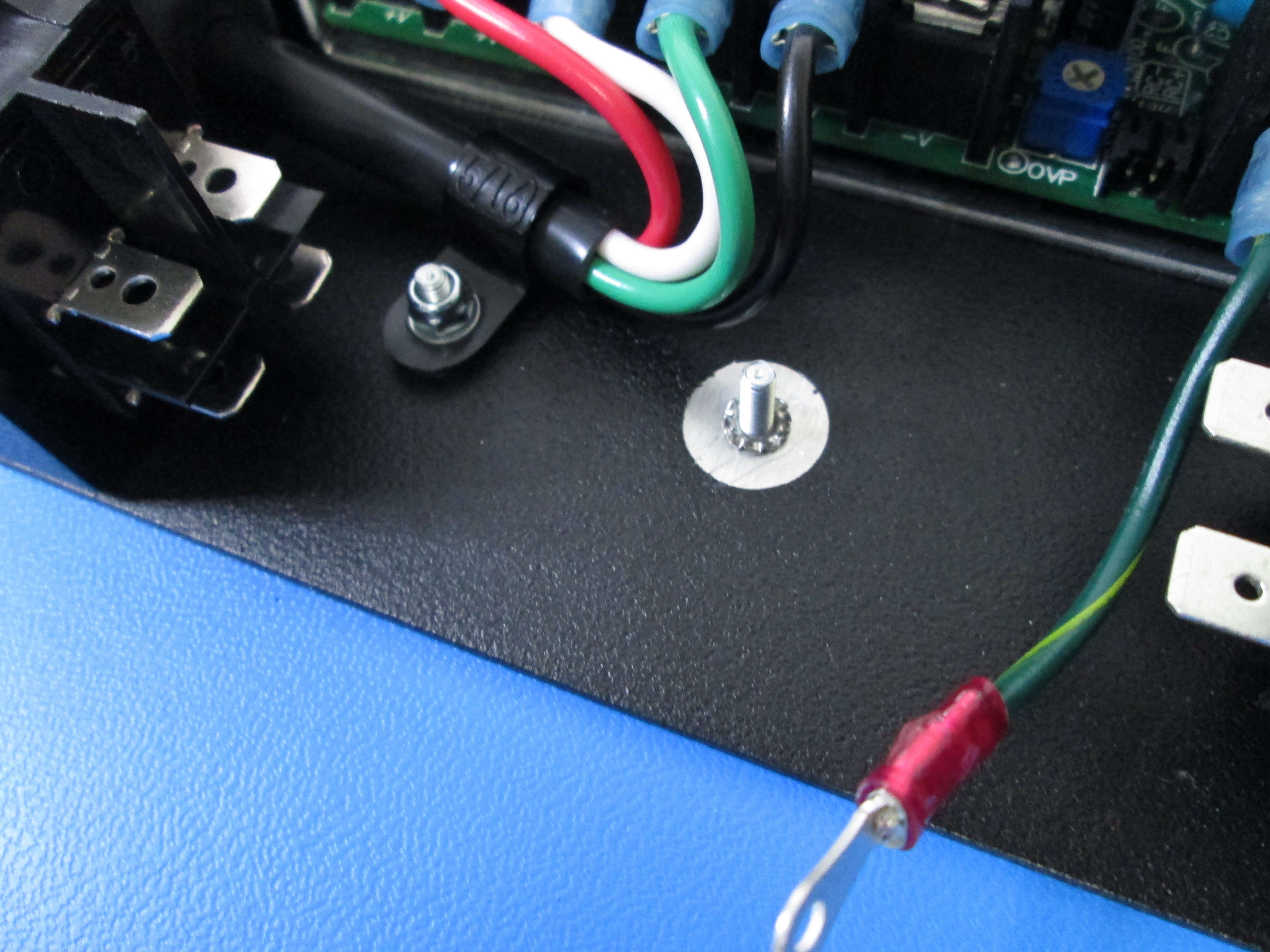
Next attach the two red terminal rings to the ground post. Make sure there is a M3 lock washer under the 2 rings. Then secure with a M3 washer and a M3 nyloc nut as shown.

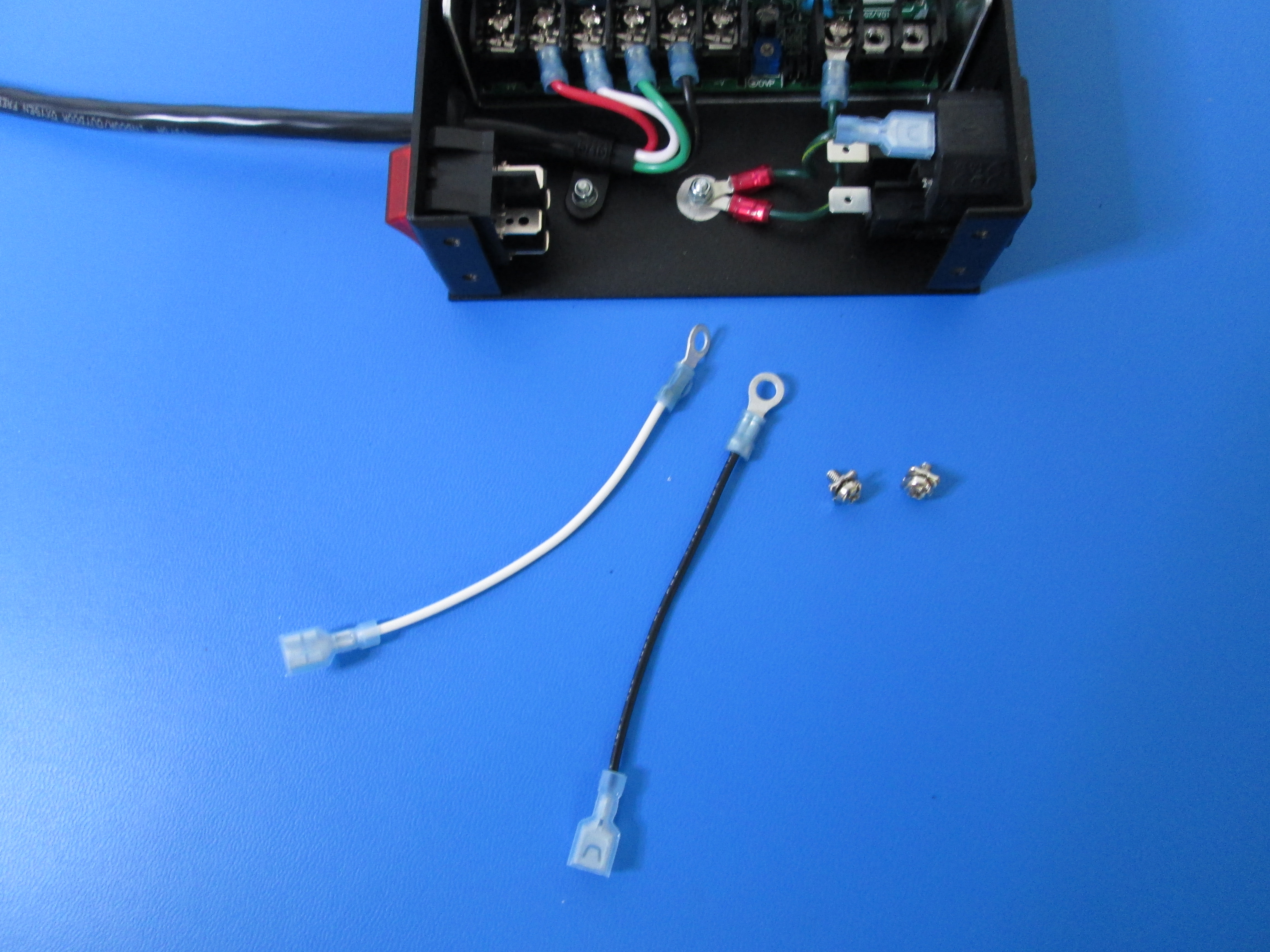
Attach the 100mm black wire and the 110mm white wire to the right terminal block as shown making sure the white wire is on the far right and the black wire is in the middle.
Next, attach the 70mm black wire to the lower back spades from the power switch to the receptacle as shown.
Next, attach the 70mm white wire to the lower front spades from the power switch to the receptacle as shown.
Attach the 100mm black wire to the upper back spade and attach the 110mm white wire to the upper front spade as shown.
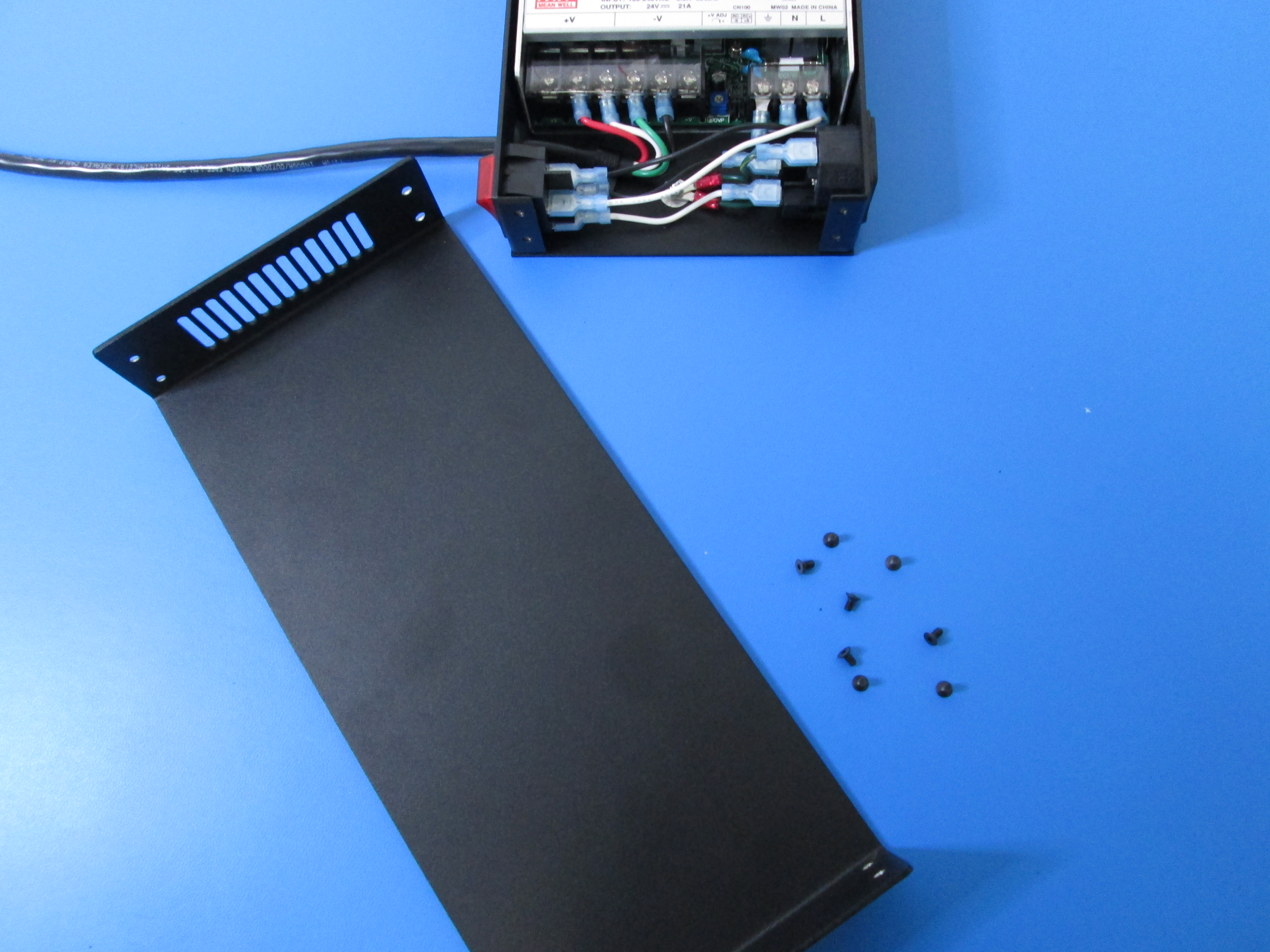
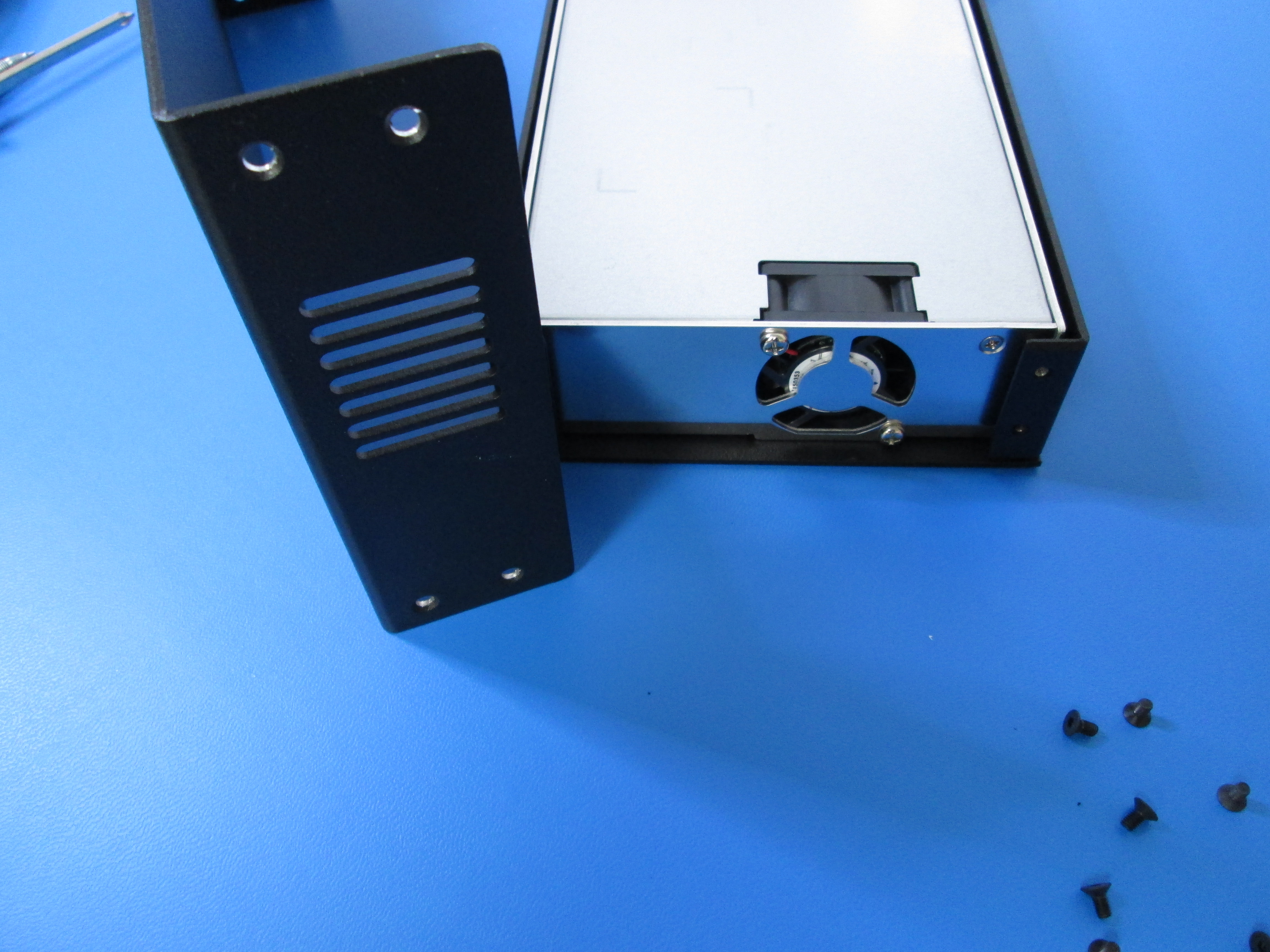
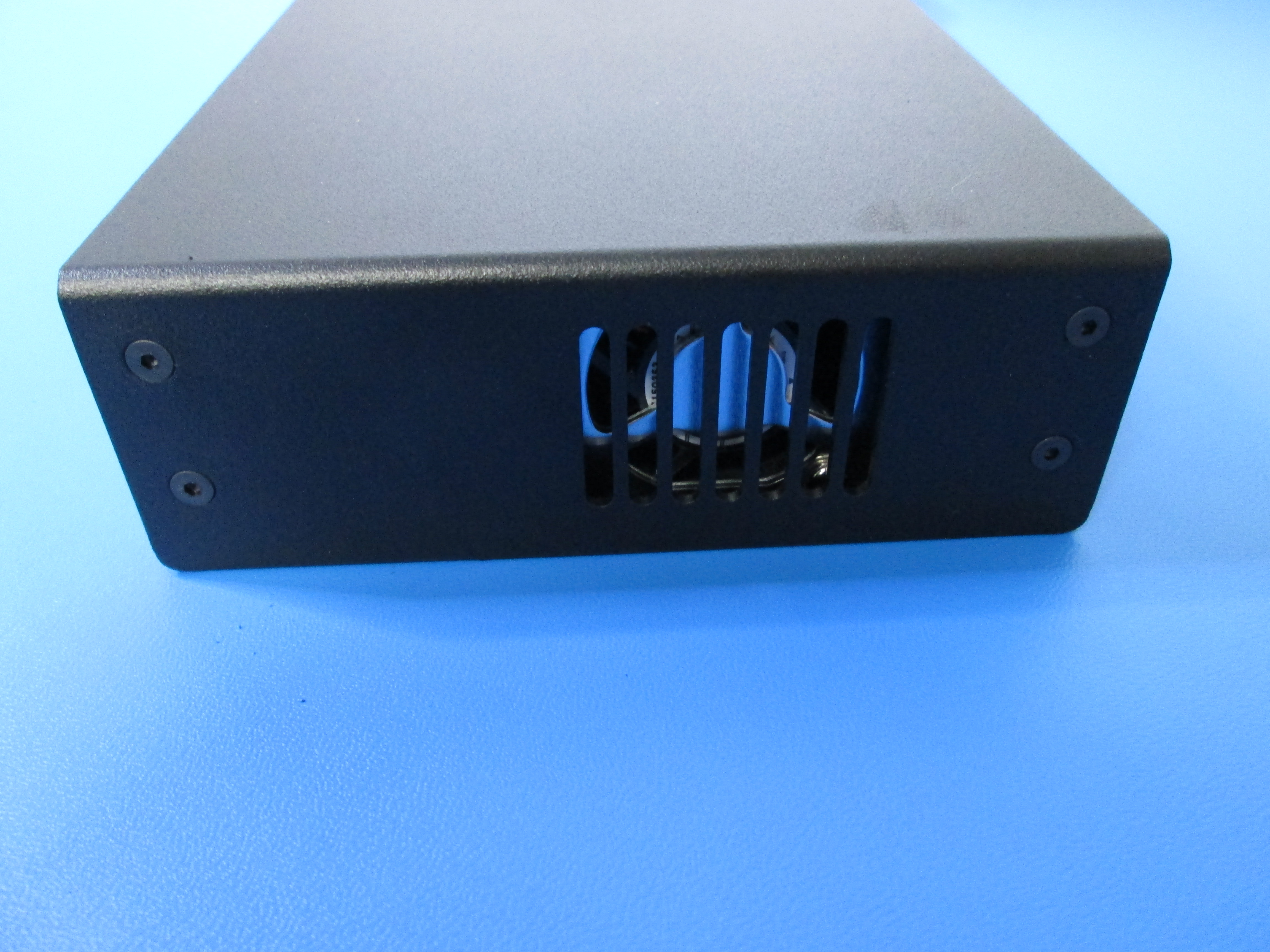
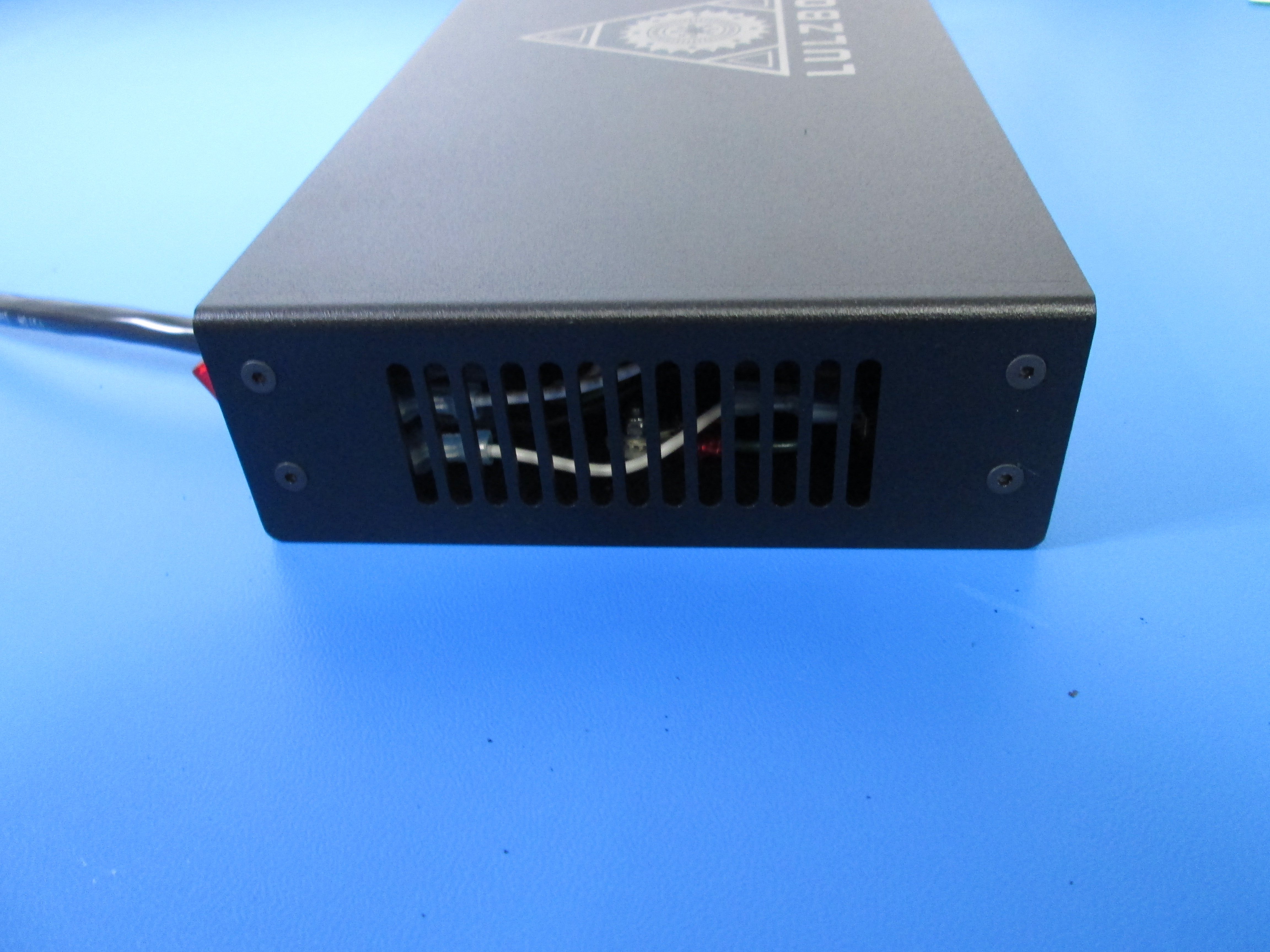
Attach the upper case to the lower case using 8x M3x6 flat head screws. Note that the smaller vent opening in the case will go towards the back where the fan is.
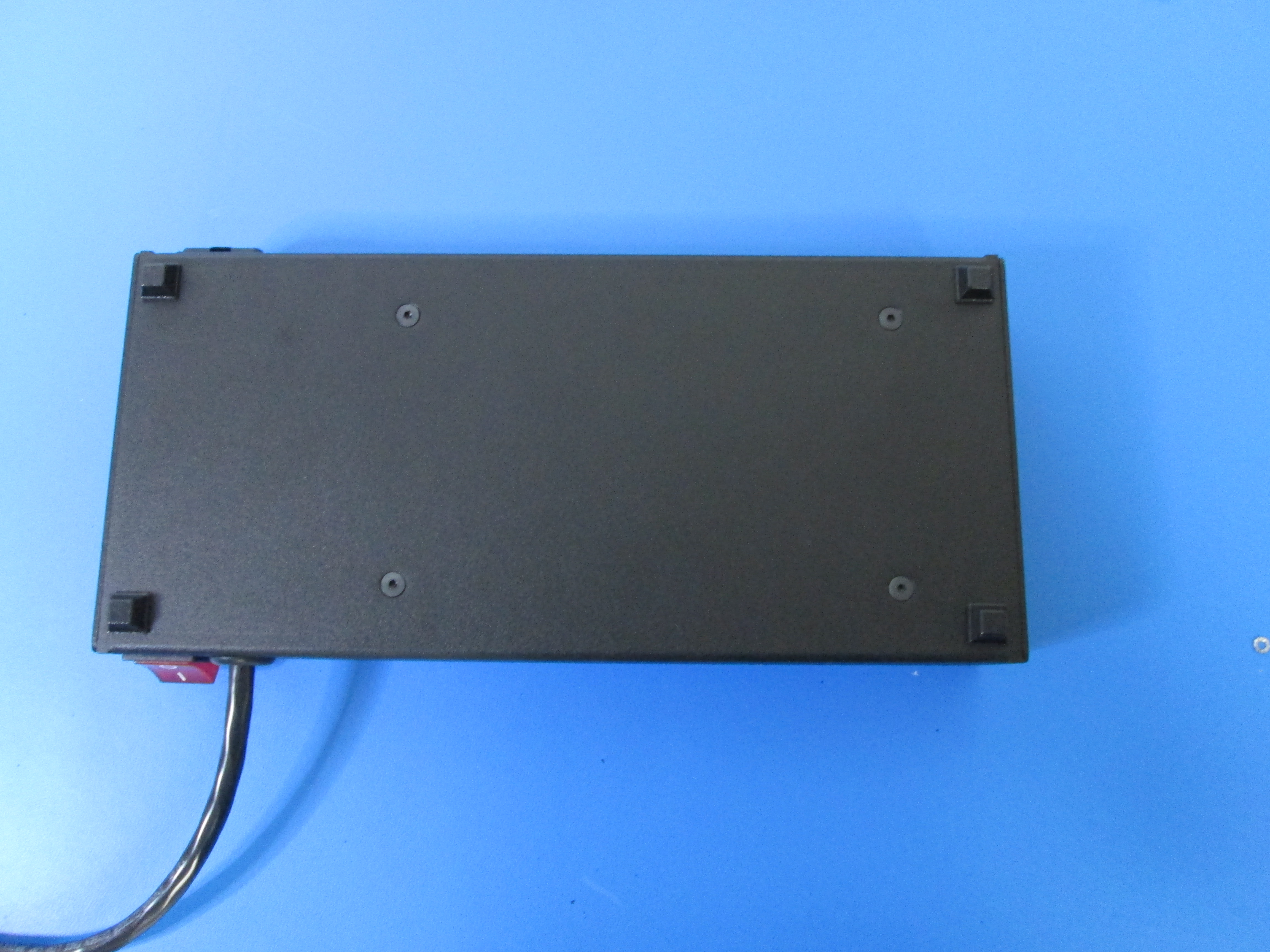
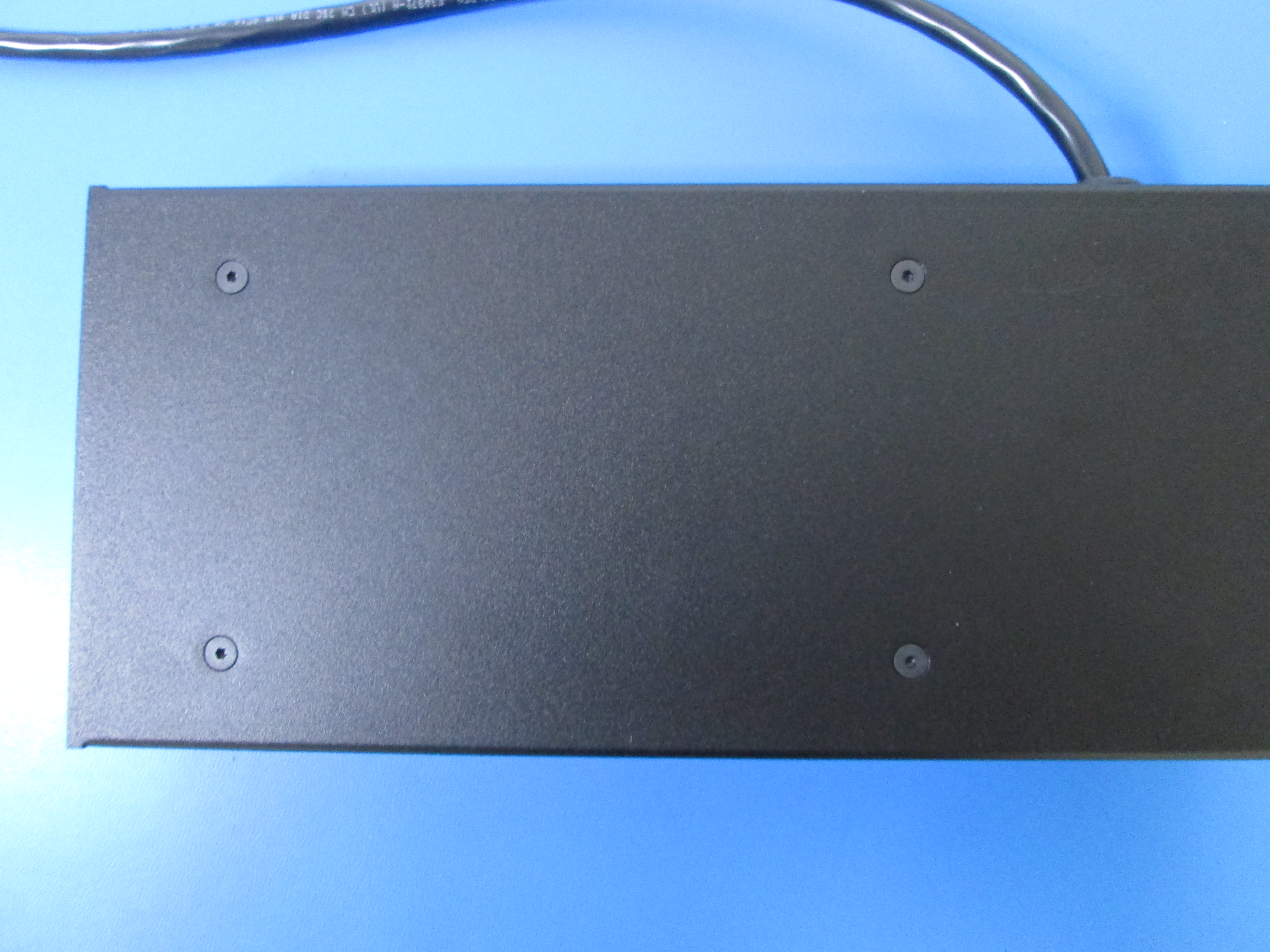
Attach 4x rubber feet to the bottom corners of the power supply as shown.