Open HardwareAssembly Instructions
Guides for installation and assembly of the LulzBot line of products made by FAME 3D LLC.
Guides for installation and assembly of the LulzBot line of products made by FAME 3D LLC.
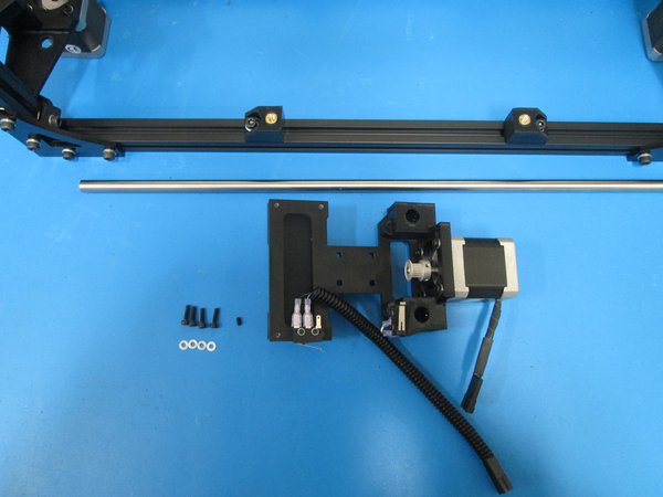
Components
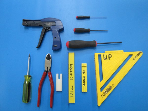
Tools

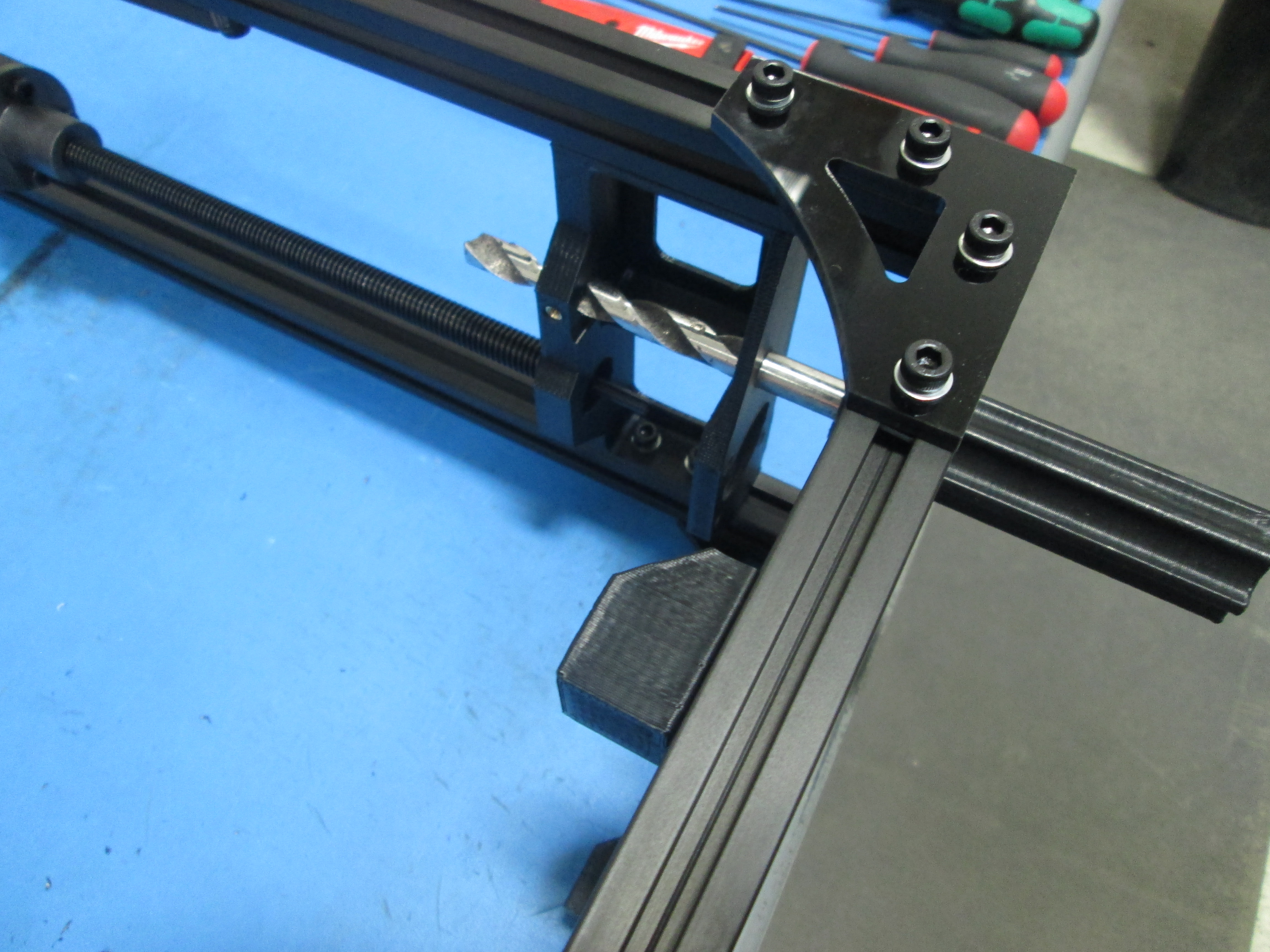
Ream out both Z motor mounts and Z tops with a 10 mm drill bit as shown.
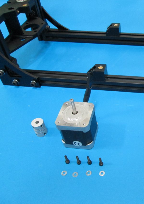
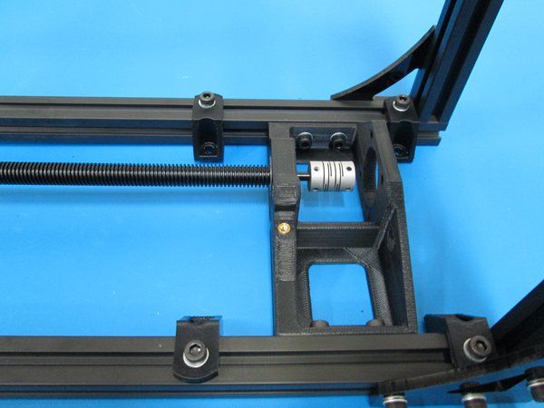
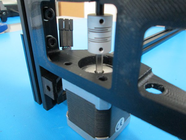
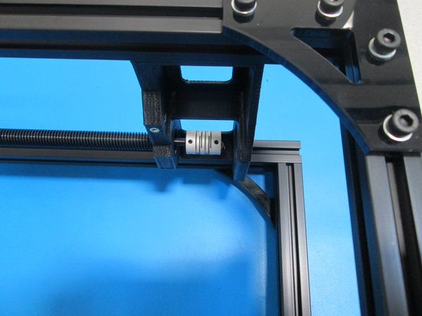
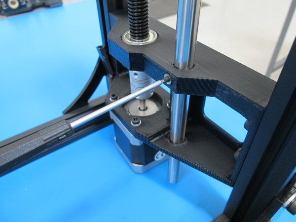
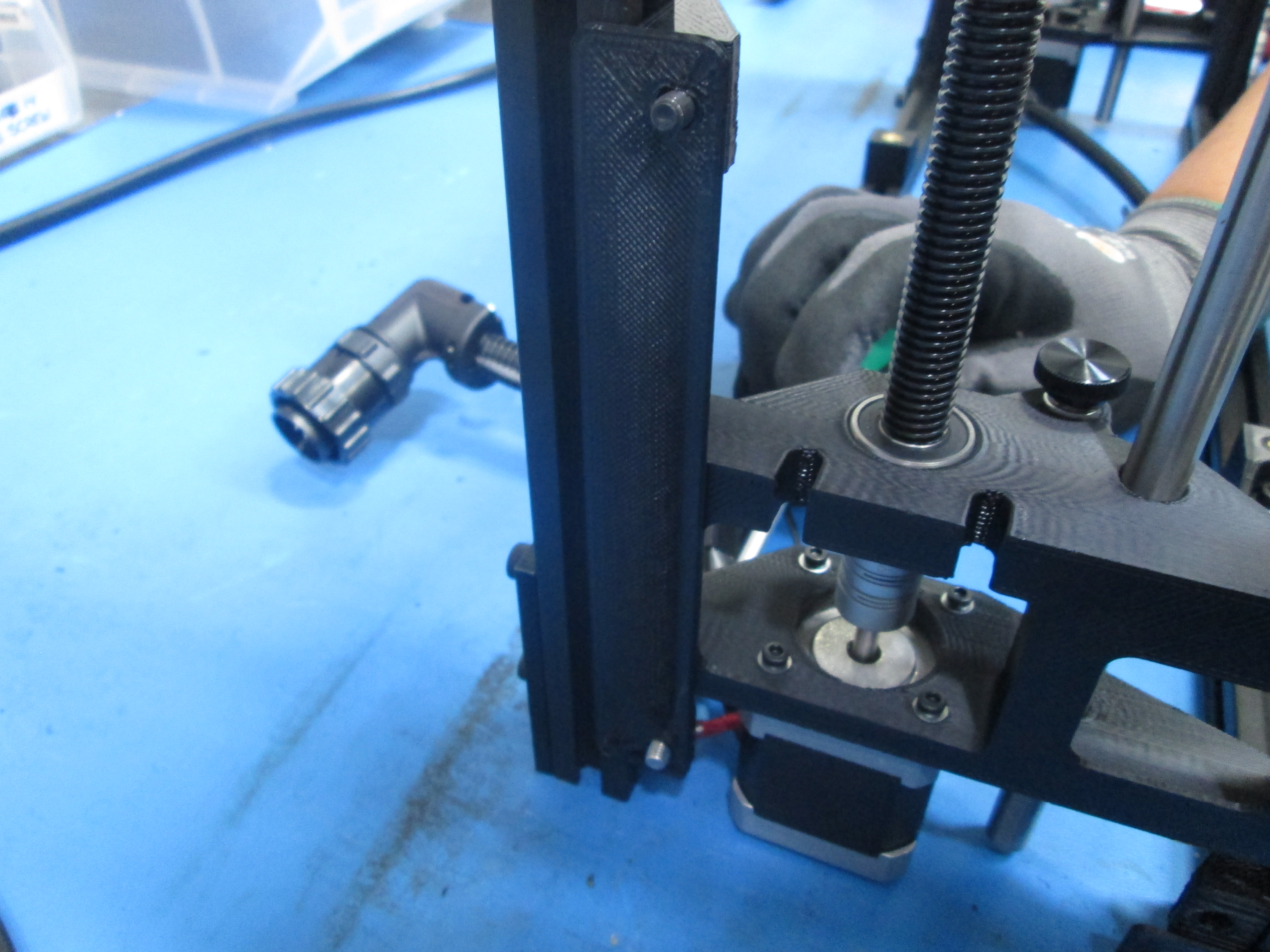
Install drive rod coupler onto drive rod, do not tighten set screws yet.
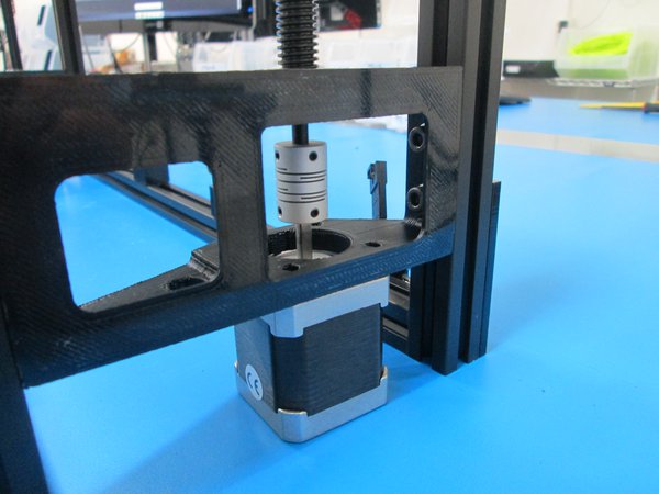
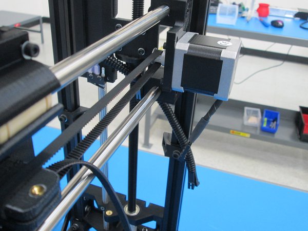
Next, install Z motor, orient wires to the back. Use 4x M3x12 SHCS and M3 washers to secure motor.
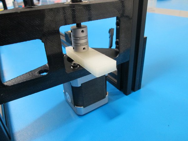
Use 8 mm spacer to set the height of the drive rod coupler. Or measure 8 mm from Z motor mount to bottom of coupler.
Make sure that one set of the coupler set screws lines up with the flat of the drive rod and flat of the motor shaft, then tighten set screws.
Tip: You may need to loosen the bolts that hold the motor to help align the coupler.

Install drive rod coupler onto drive rod, do not tighten set screws yet.
Next, install Z motor, orient wires to the back. Use 4x M3x12 SHCS and M3 washers to secure motor.
Use 8 mm spacer to set the height of the drive rod coupler. Or measure 8 mm from Z motor mount to bottom of coupler.
Make sure that one set of the coupler set screws lines up with the flat of the drive rod and flat of the motor shaft, then tighten set screws.
Tip: You may need to loosen the bolts that hold the motor to help align the coupler.


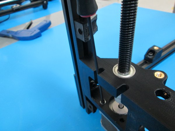
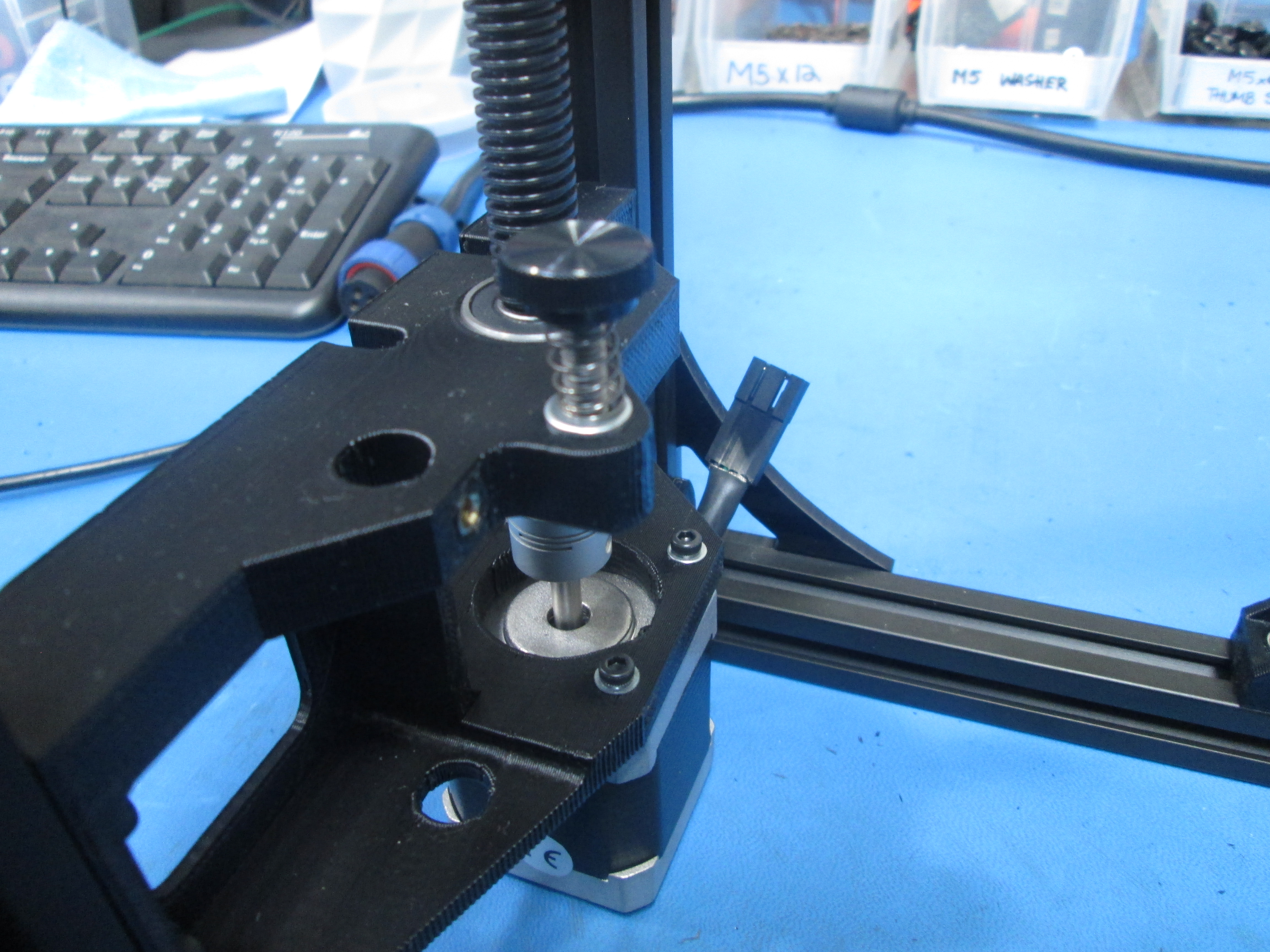
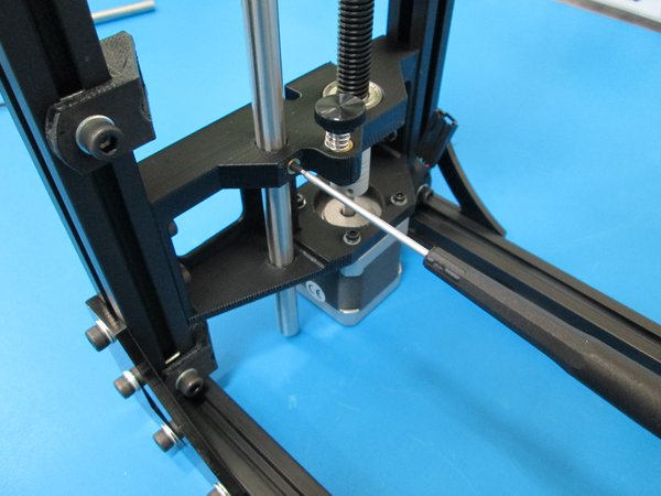
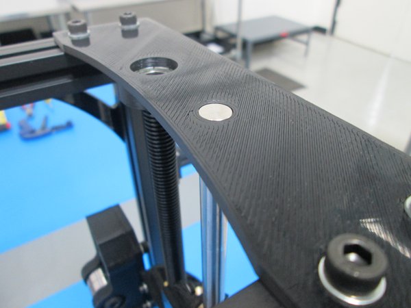
Place Z adjustment spring on M5x20 thumb screw.
Place a M5 washer on the screw then thread it into the threaded insert on the left Z motor mount.
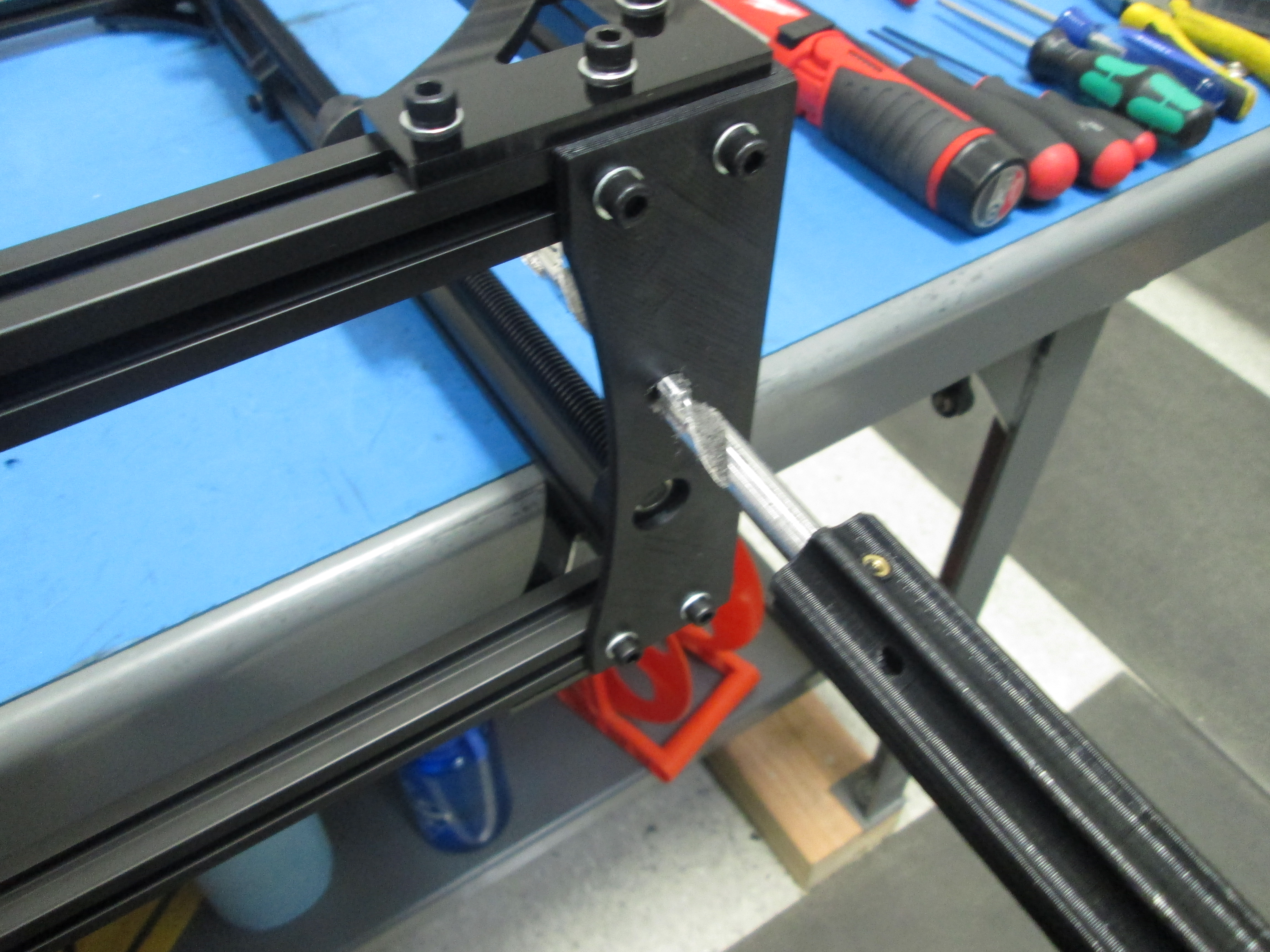
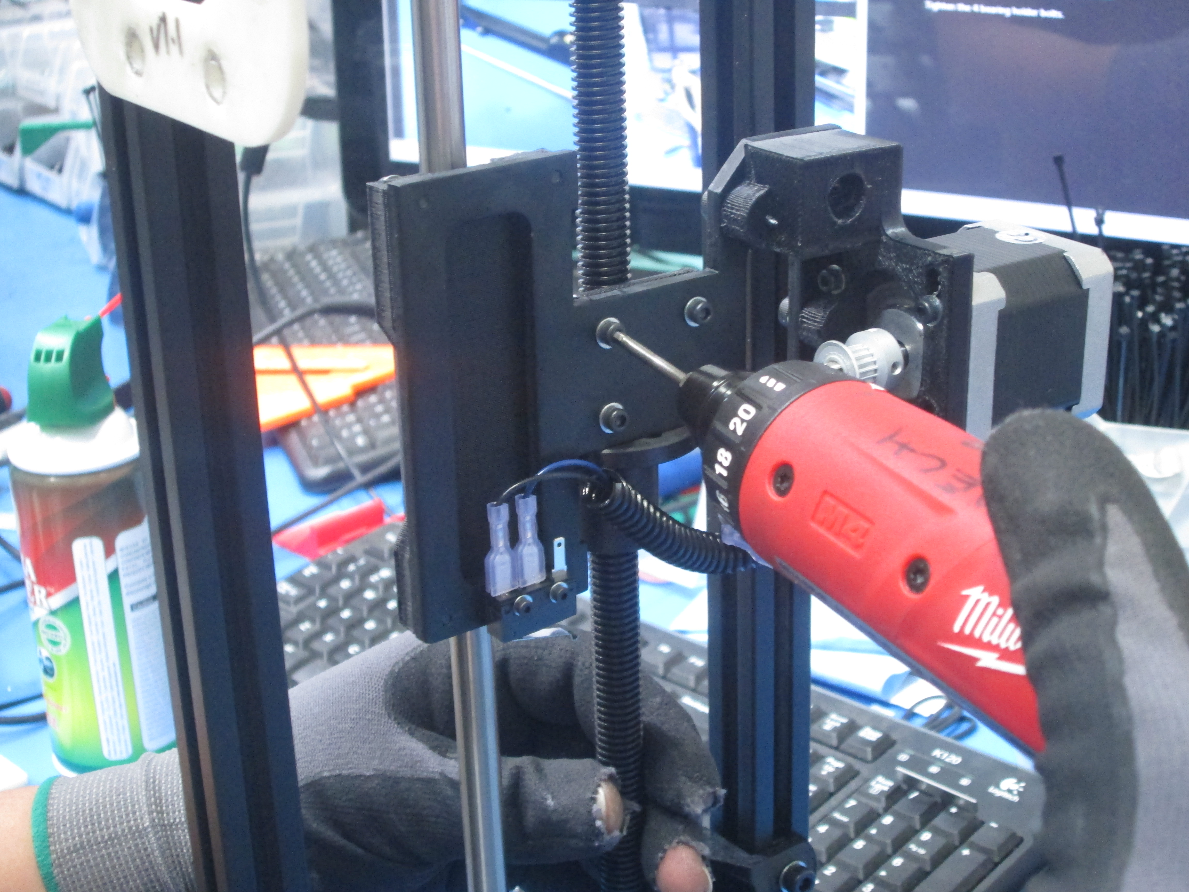
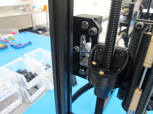
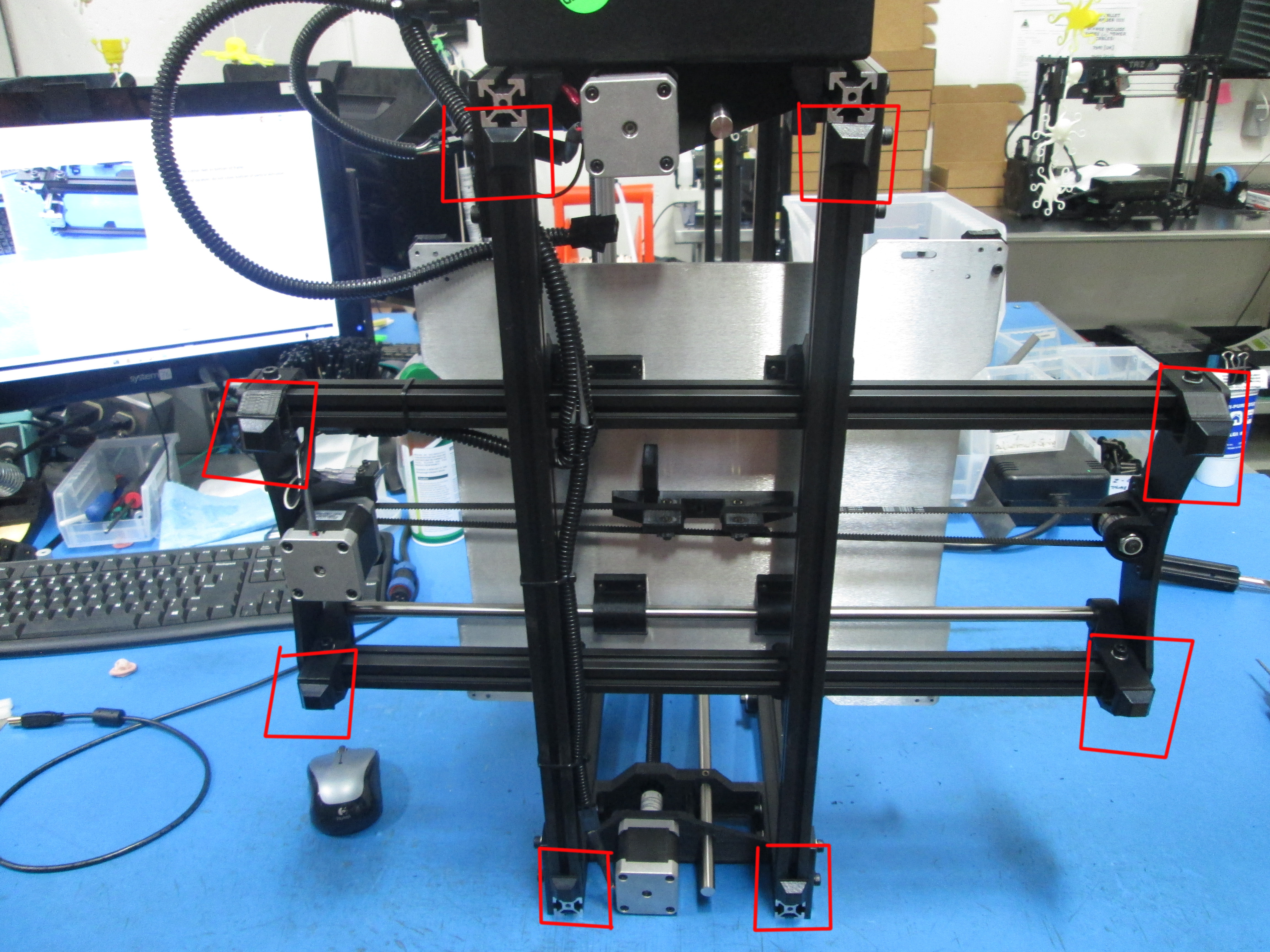
Ream out the X end motor mount with the 10 mm drill bit the same as you did to the Z motor mount and Z tops.
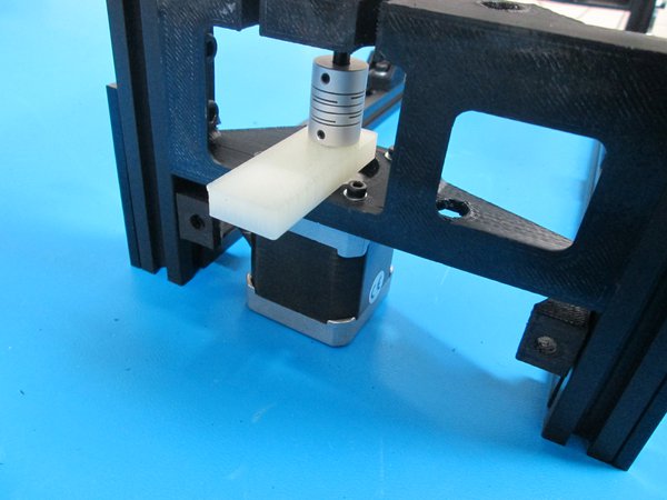
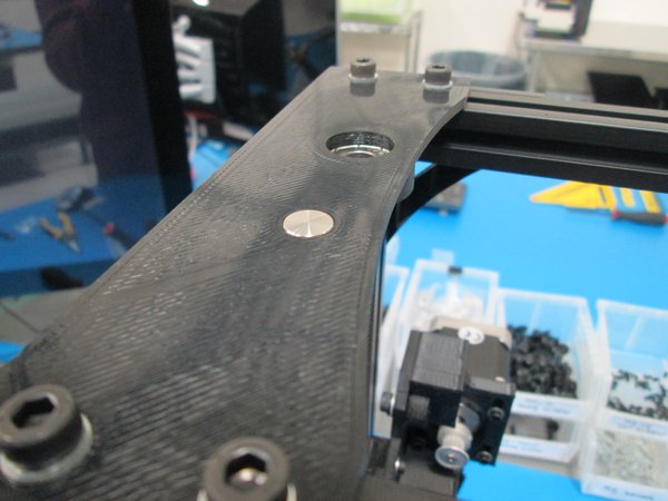
Use 4x M3x12 SHCS wih M3 washers to attach the X end motor sub assembly to the Z nut mount as shown.
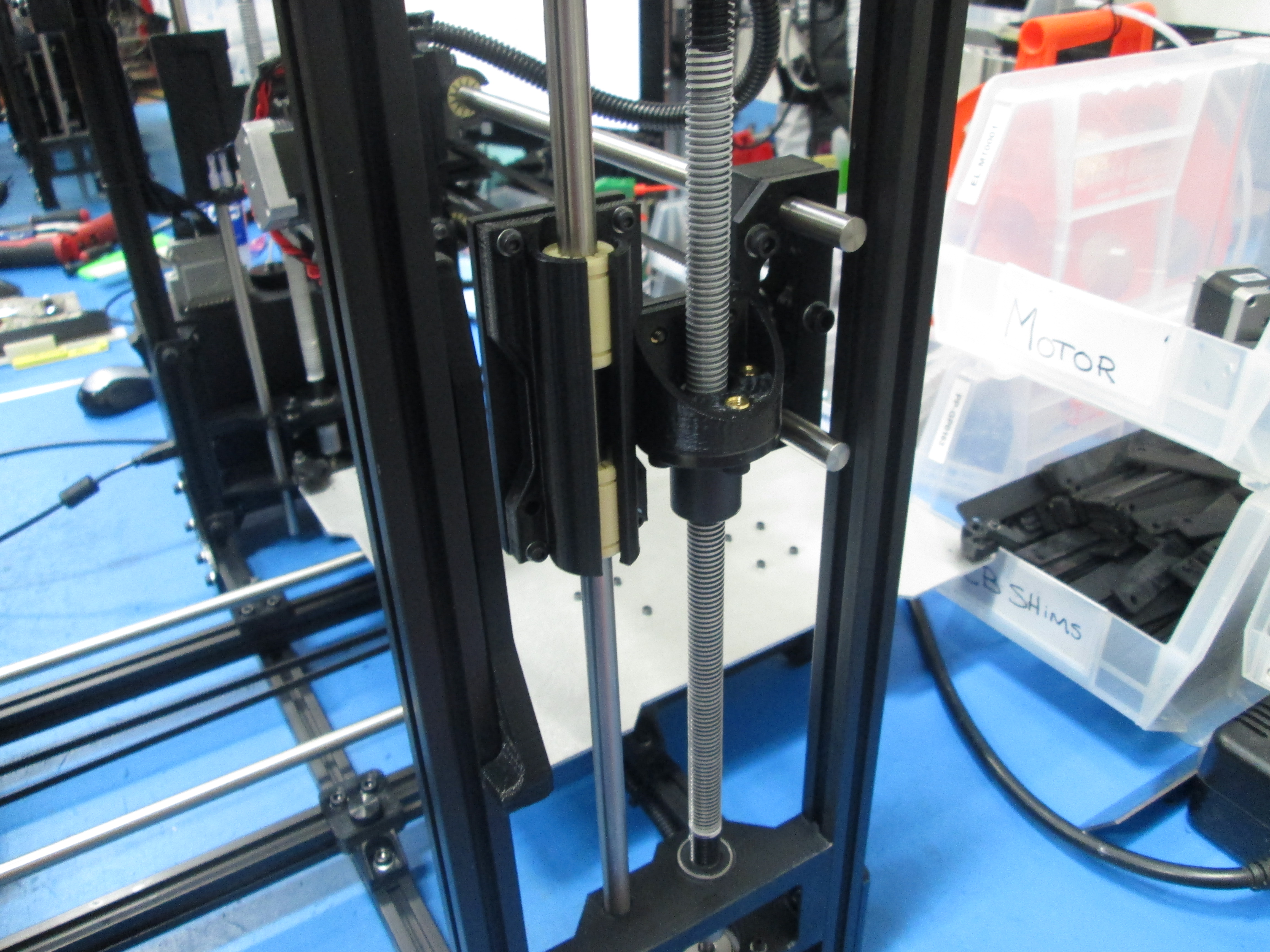
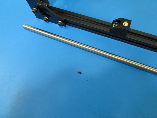
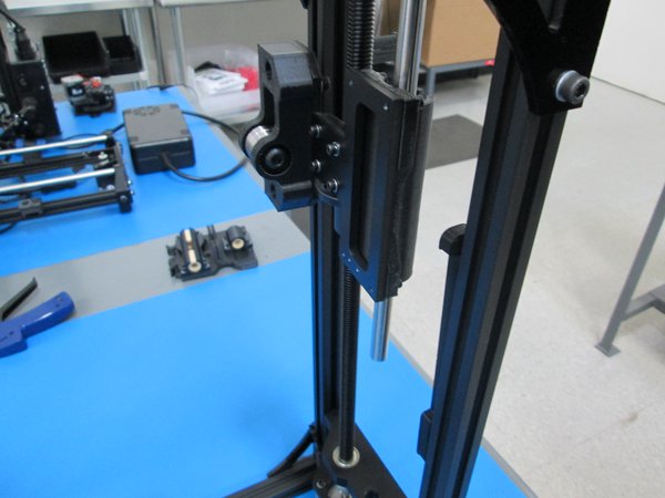
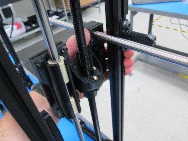
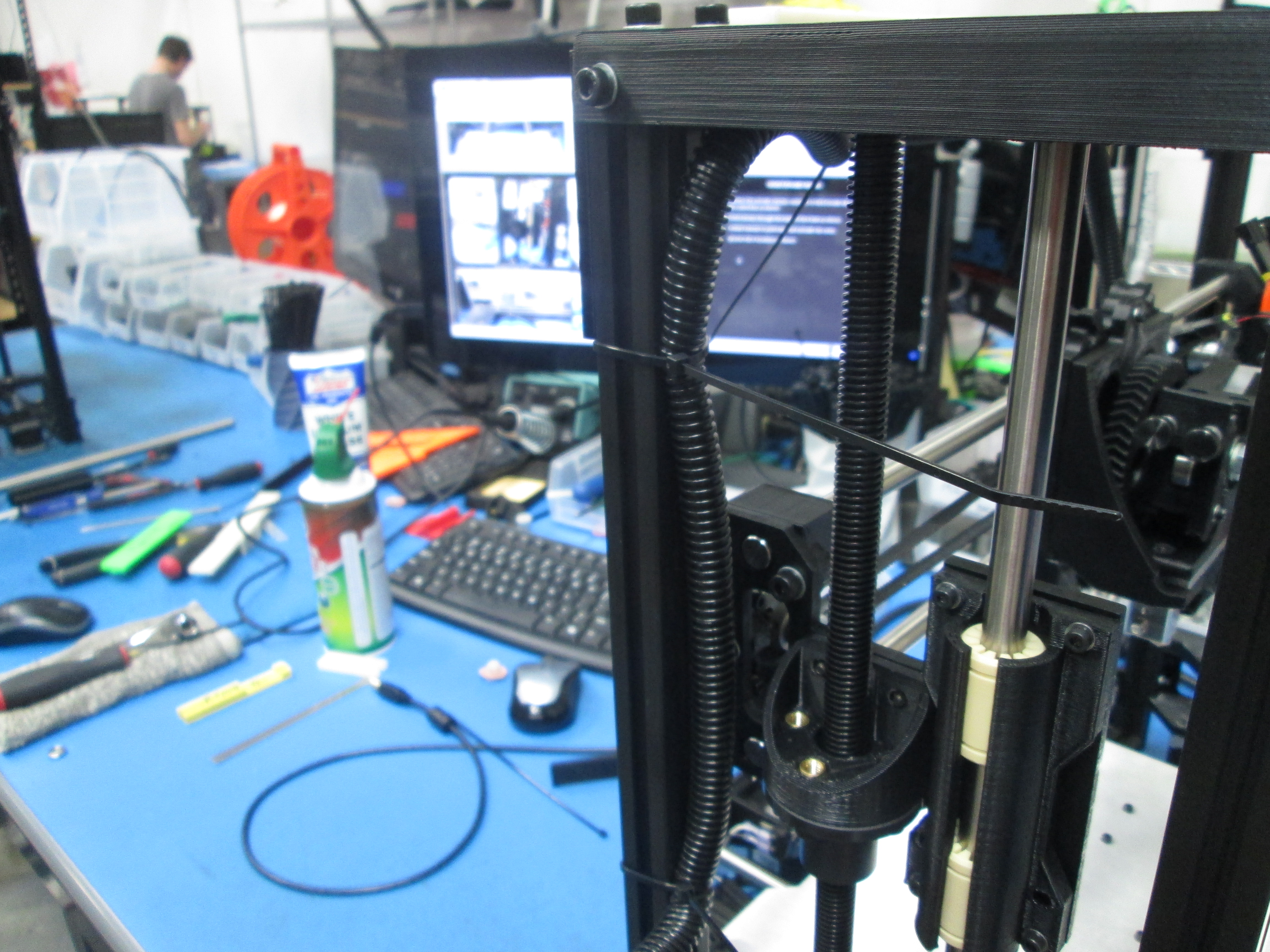
Slide the 10x500mm smooth rod down through the Z top, make sure the smooth rod is flush with the Z top.
Use M3x6 set screw to secure the smooth rod.
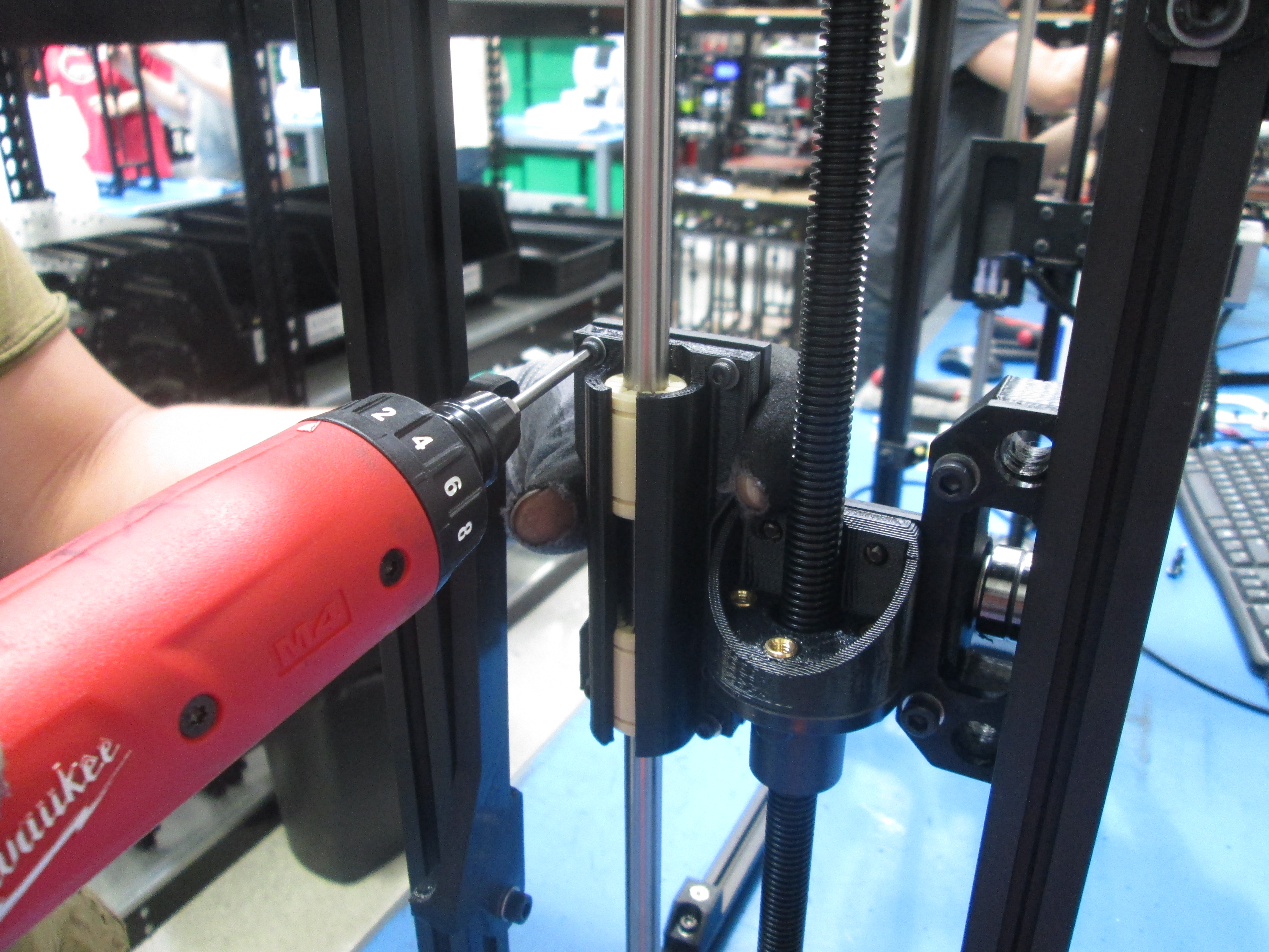
Tighten the 4 bearing holder bolts.
Make sure the drive rods rotate smoothly, make adjustments as necessary. You may need to loosen the bearing holder bolts or the 4 bolts that secure it to the Z nut mount and re-tighten them to free up the drive rods.

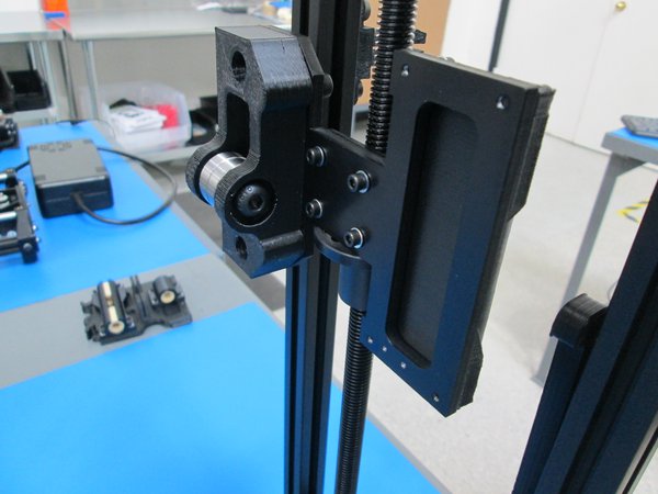
Ream out the X end idler with the 10 mm drill bit the same as you did to the Z motor mount and Z tops.
Use 4x M3x12 SHCS wih M3 washers to attach the X end idler sub assembly to the Z nut mount as shown.
Slide the 10x500mm smooth rod down through the Z top, make sure the smooth rod is flush with the Z top.
Use M3x6 set screw to secure the smooth rod.
Tighten the 4 bearing holder bolts.
Make sure the drive rods rotate smoothly, make adjustments as necessary. You may need to loosen the bearing holder bolts or the 4 bolts that secure it to the Z nut mount and re-tighten them to free up the drive rods.


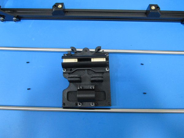
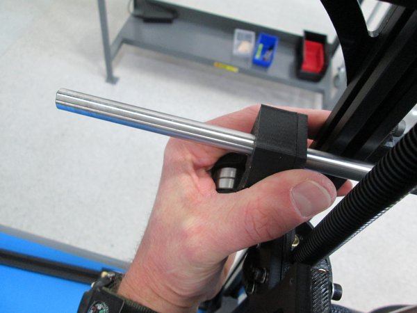
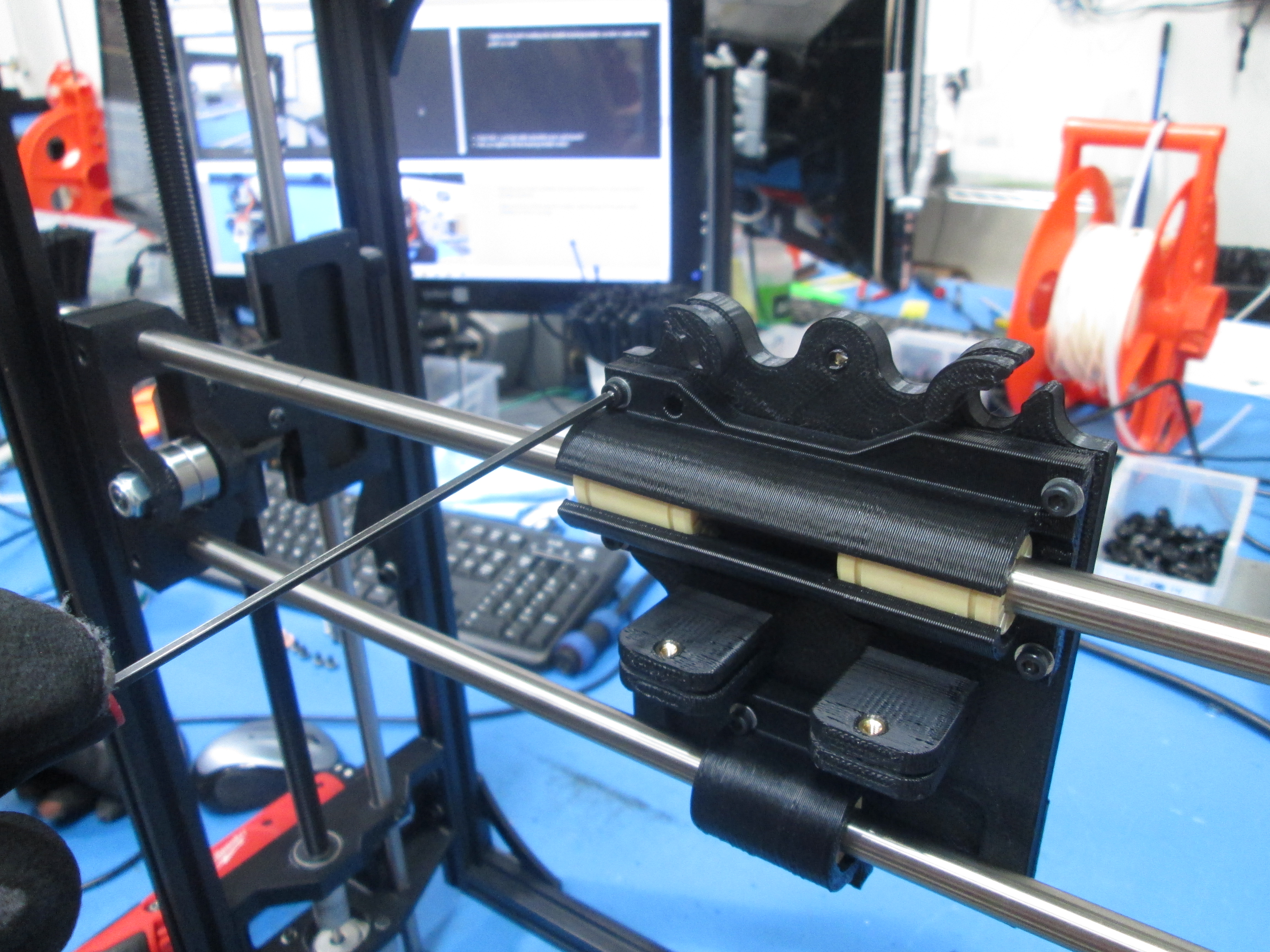
Slide a 10mm rod through one of the two holes in the X end idler.
Once its through far enough, put the X carriage on the rod.
Finish sliding the 10mm rod through until it's also inserted into the X end motor.
The rod will be flush with the outside of the X end motor.
Repeat with the second 10mm rod in the second set of holes.
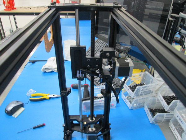
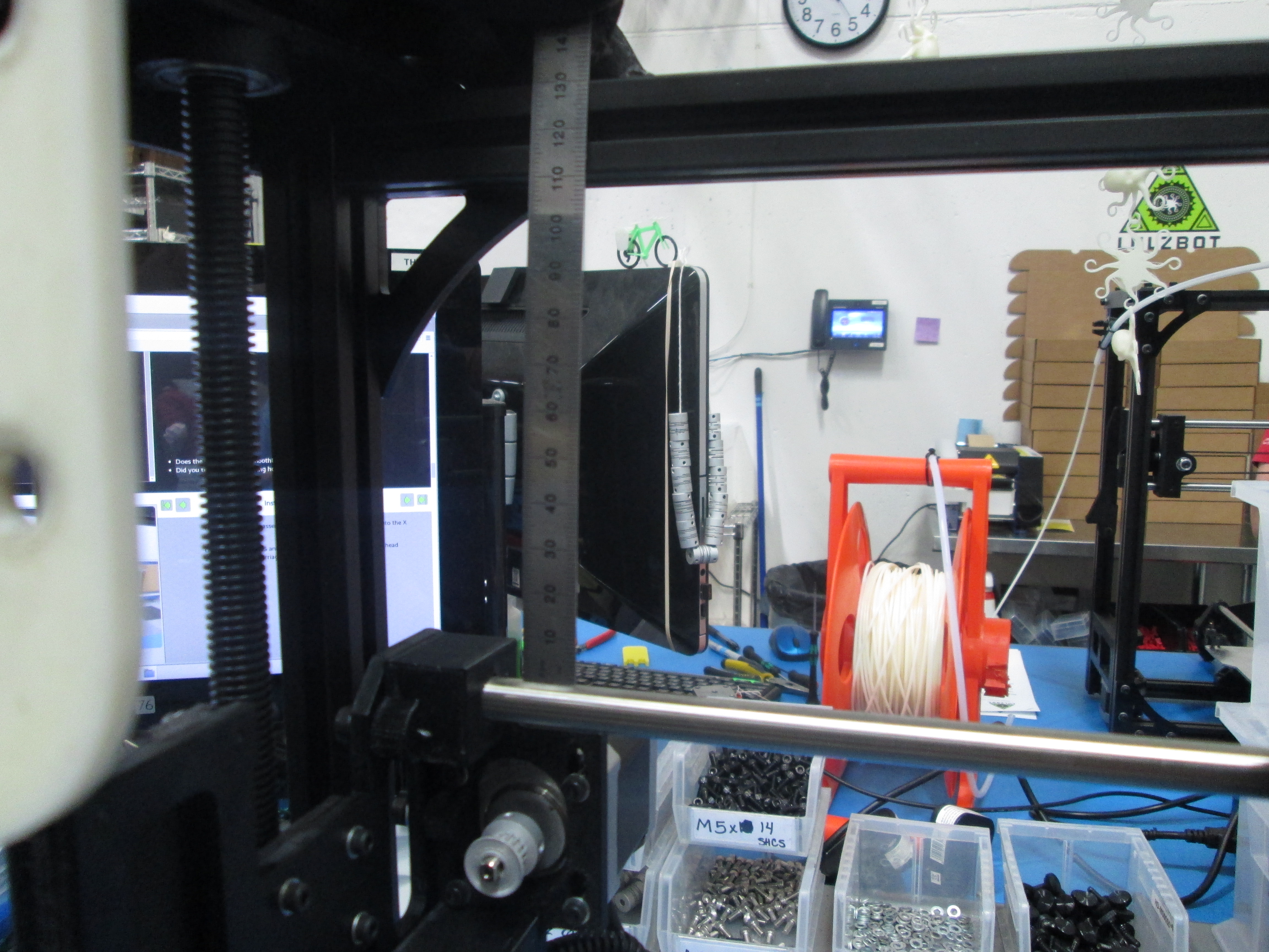
Check the distance to the top with a ruler on both sides to assure that the two sides are level as shown.
Using 4 M3x6 set screws, lock the rods in place at the X ends.
Tighten the bolts holding the bearing holders on the X carriage making sure it still slides freely back and forth.


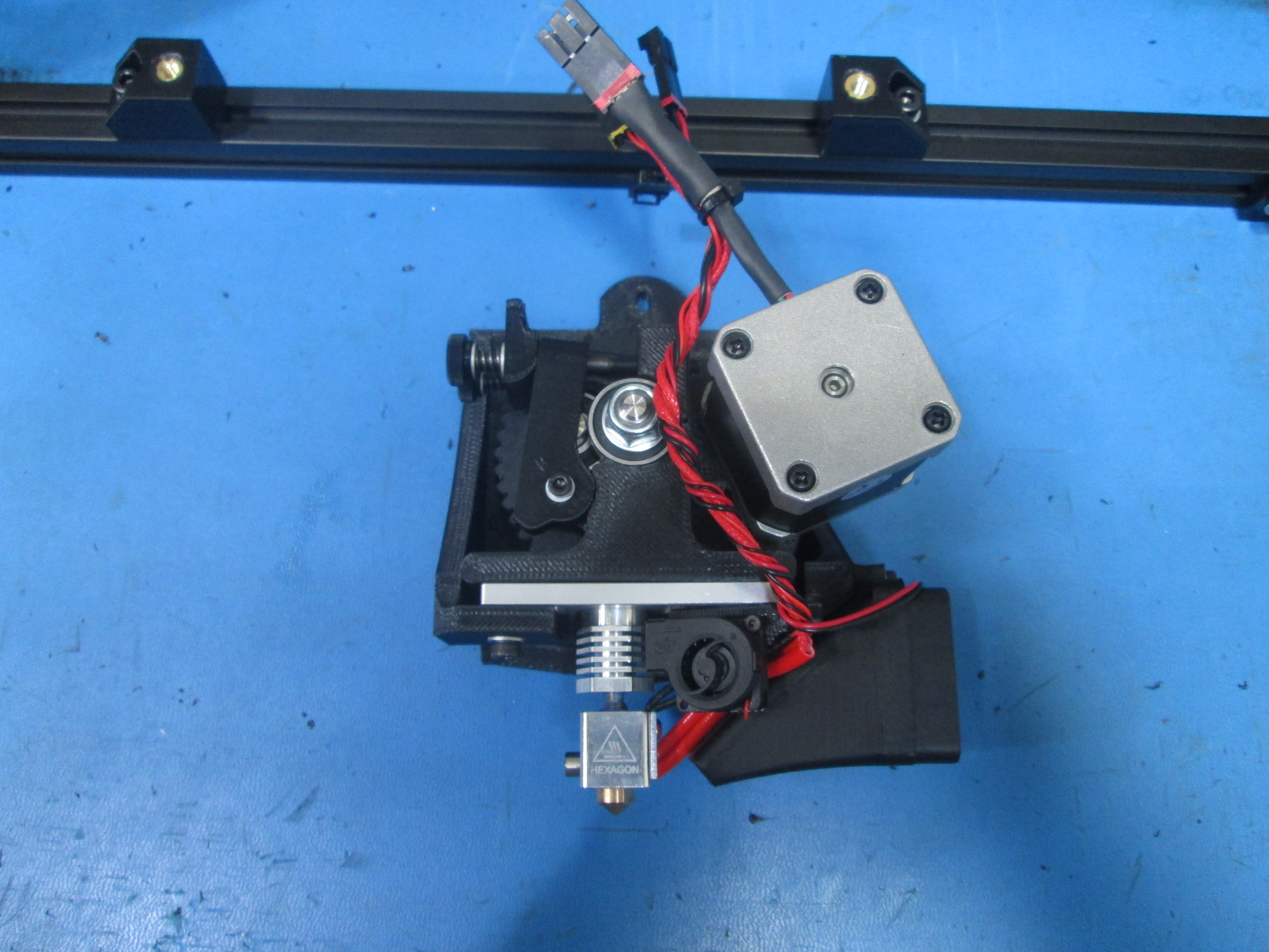
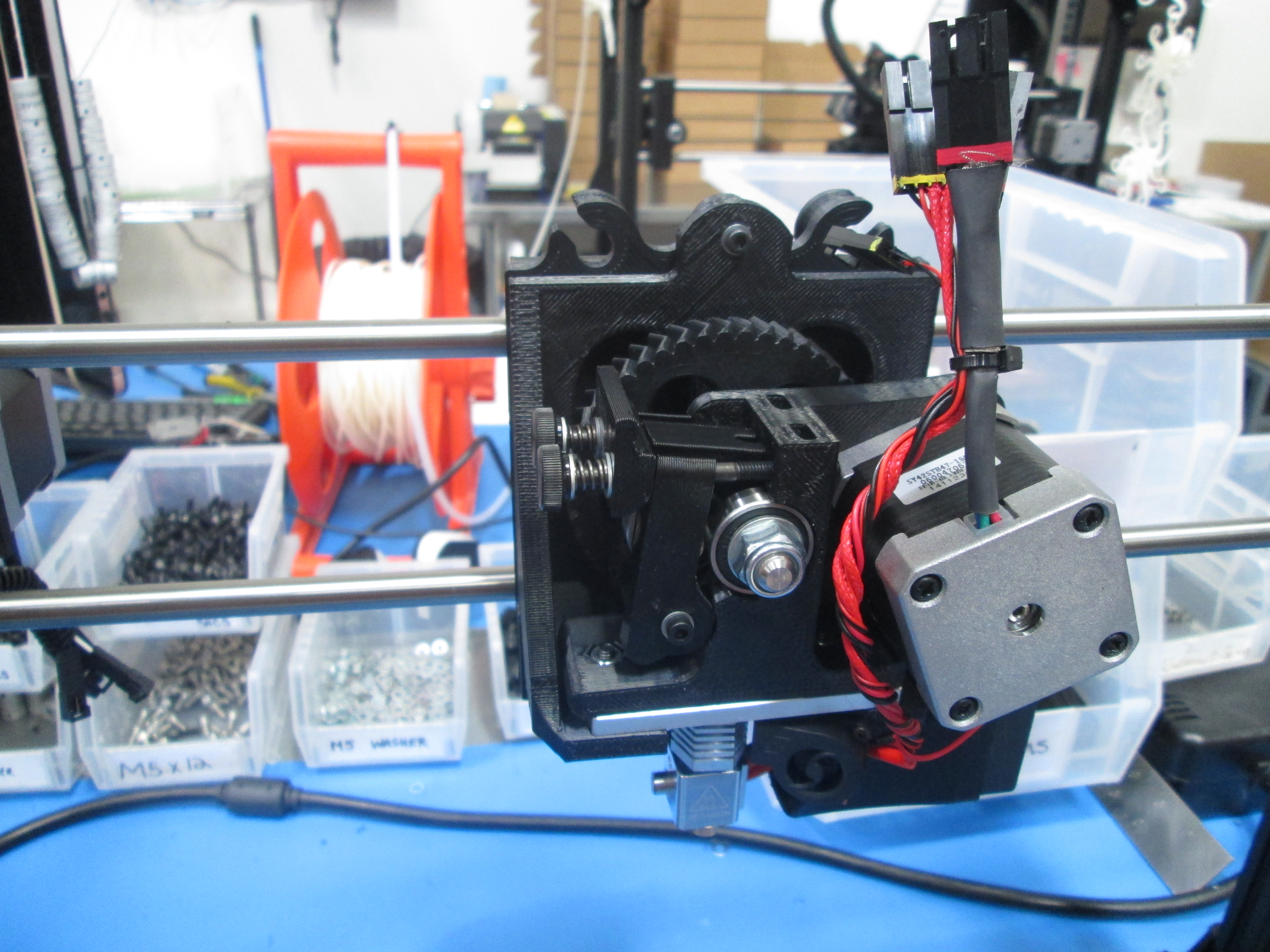
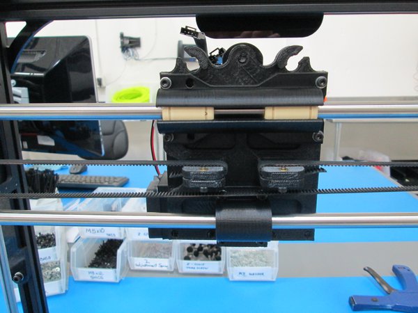
Take the print head assembly and seat the bottom of it down into the X carriage assembly.
Using a M3x12 SHCS and M3 washer, bolt the top of the print head assembly to the X carriage.
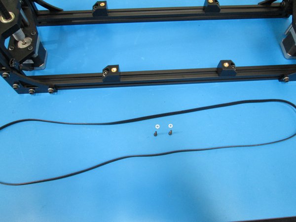
First cut the belt with a side cutters.
Route one end through the X carriage as shown and clamp down with a M3x12 SHCS and M3 Washer.
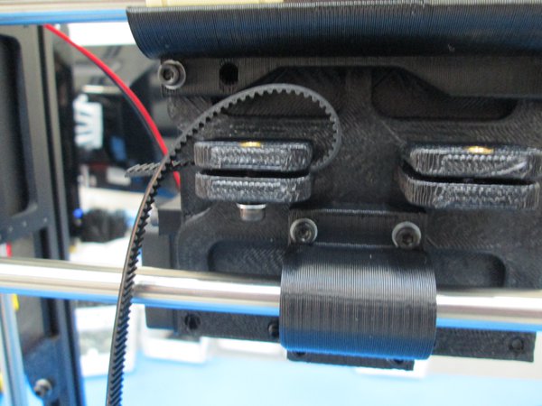
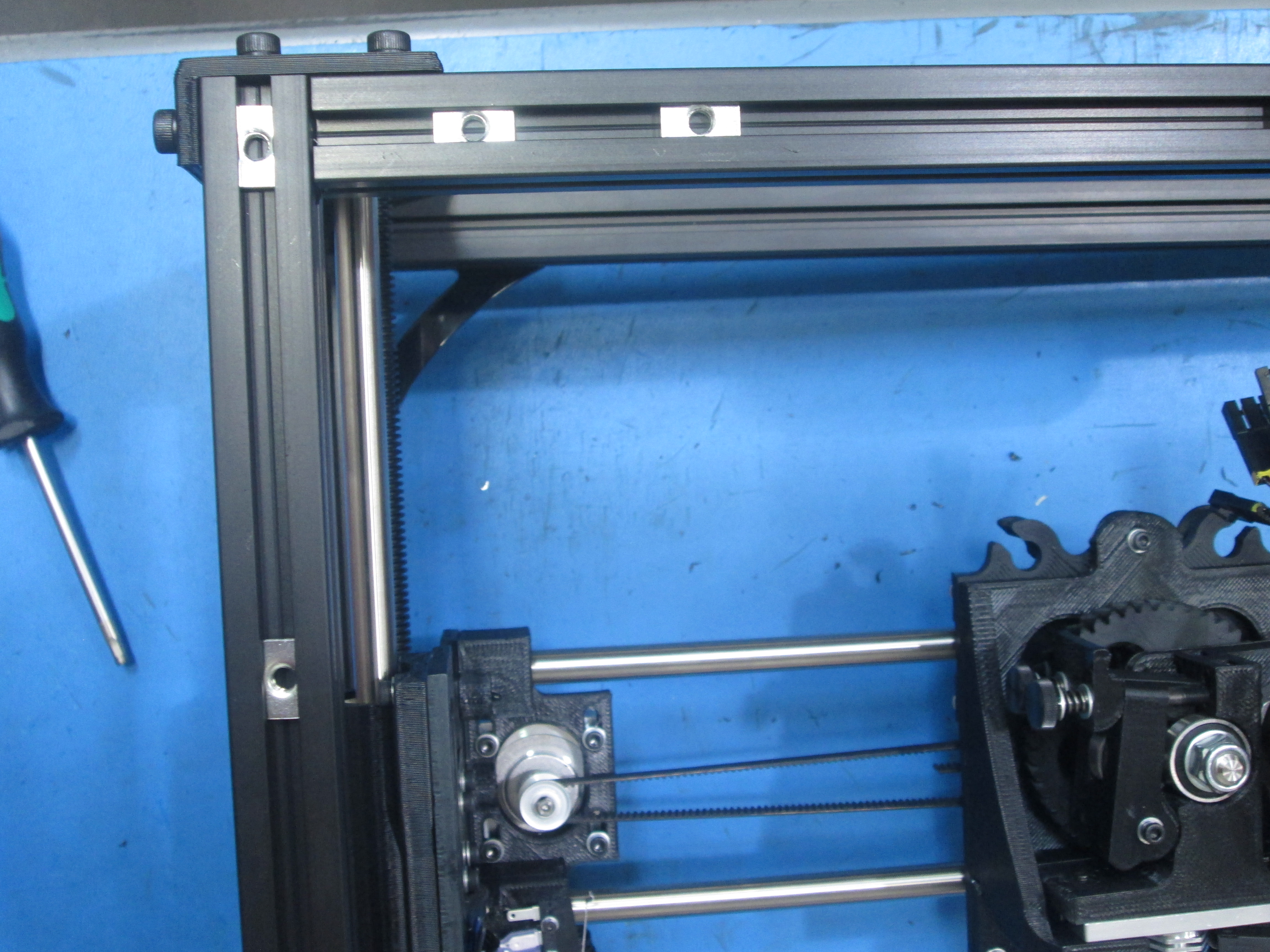
Next route the belt around the pulley on the X end motor and the bearings on the X end idler.
Finish routing the belt back at the X carriage.
Pull tight, with pliers, and clamp down with a M3x12 SHCS and M3 Washer.
Trim the ends of the belt so they do not interfere with the pulley or bearings.
Check for belt rubbing as you move the X carriage back and fourth. Adjust as necessary. Also make sure the belt tracks in the middle of the idler bearing.


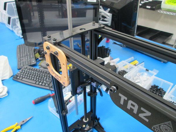
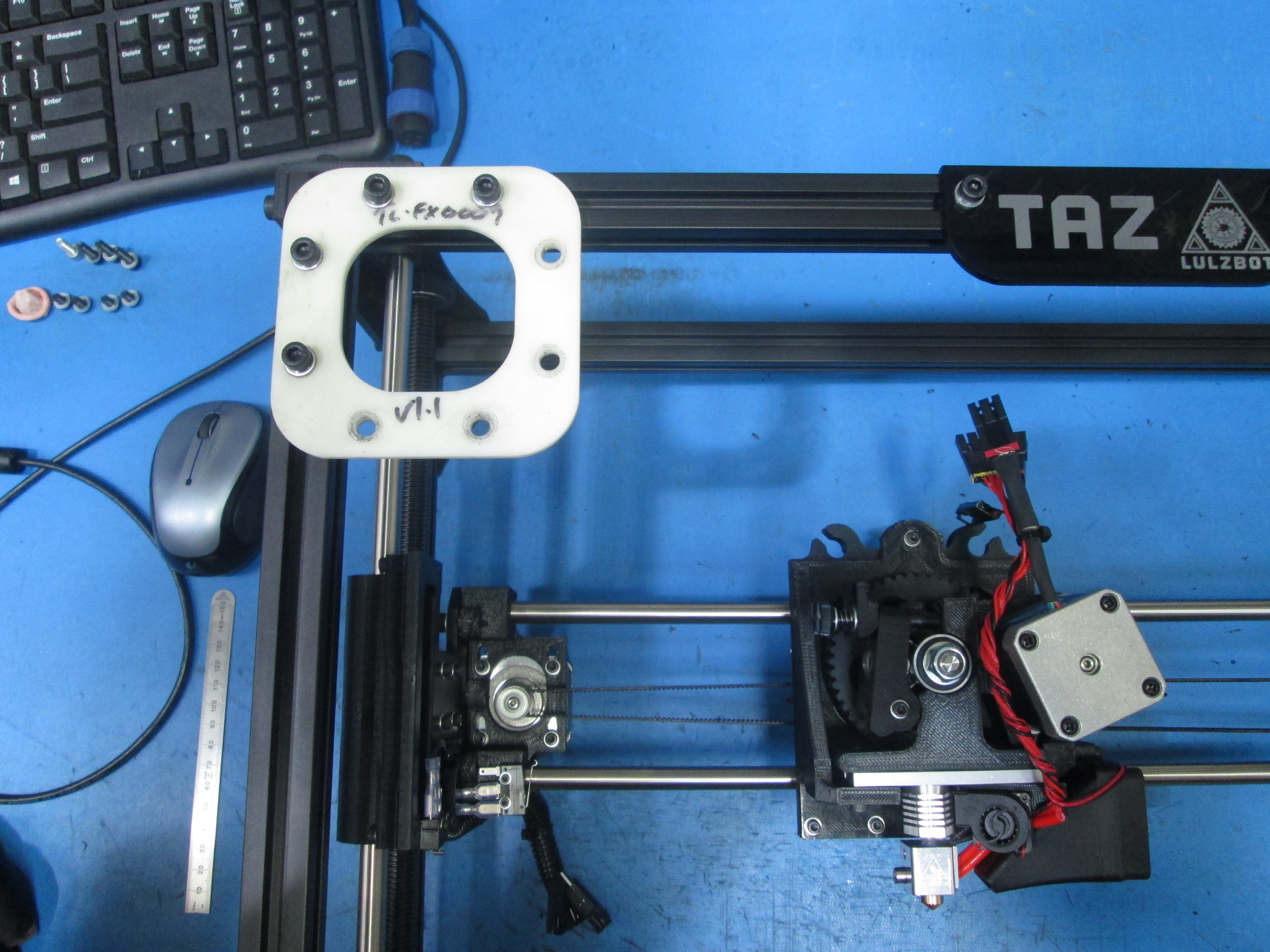
Remove the assembly fixture TL-FX0009 from the corner of the frame.
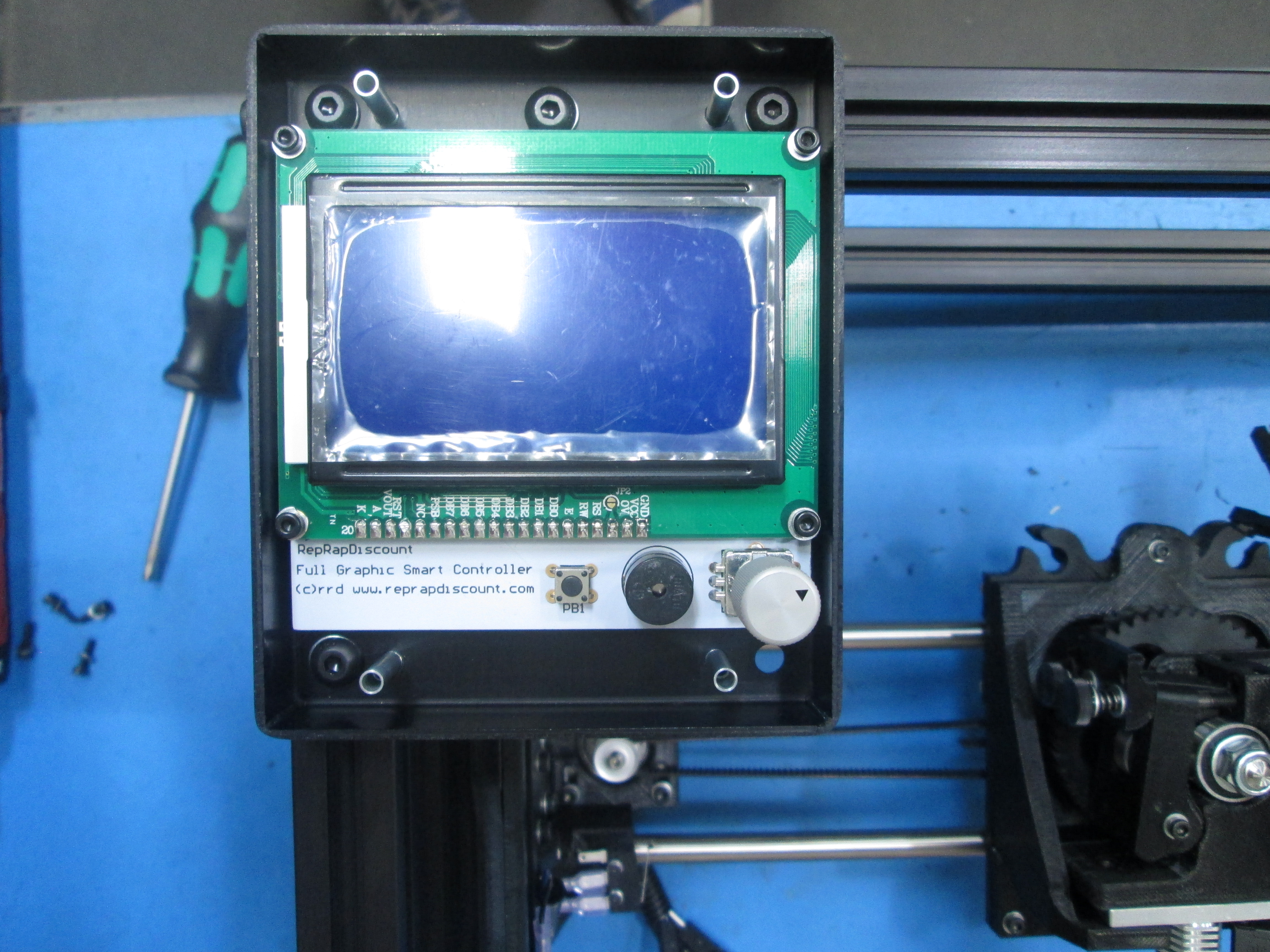
Using the already installed M5 T-nuts along with 4x M5x8 BHCS and M5 Washers, attach the LCD case assembly to the frame.
Set the edge and top of the LCD case flush with the outside of the frame.
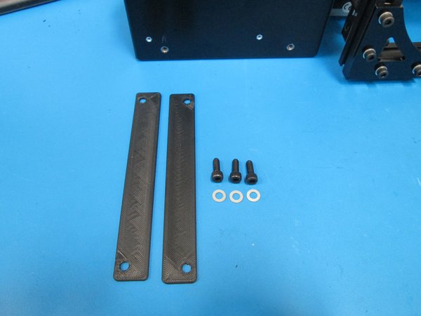
Using 4x M3x12 SHCS and M3 Washers, attach the LCD cover.


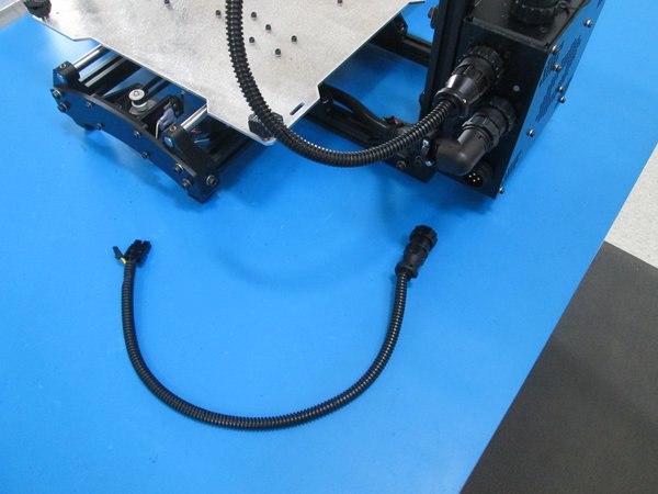
Attach the YZ cable to the Z left motor as shown.
Use the M5x12 Stainless SHCS to attach the ground cable in the bottom back electronic case mount as shown.
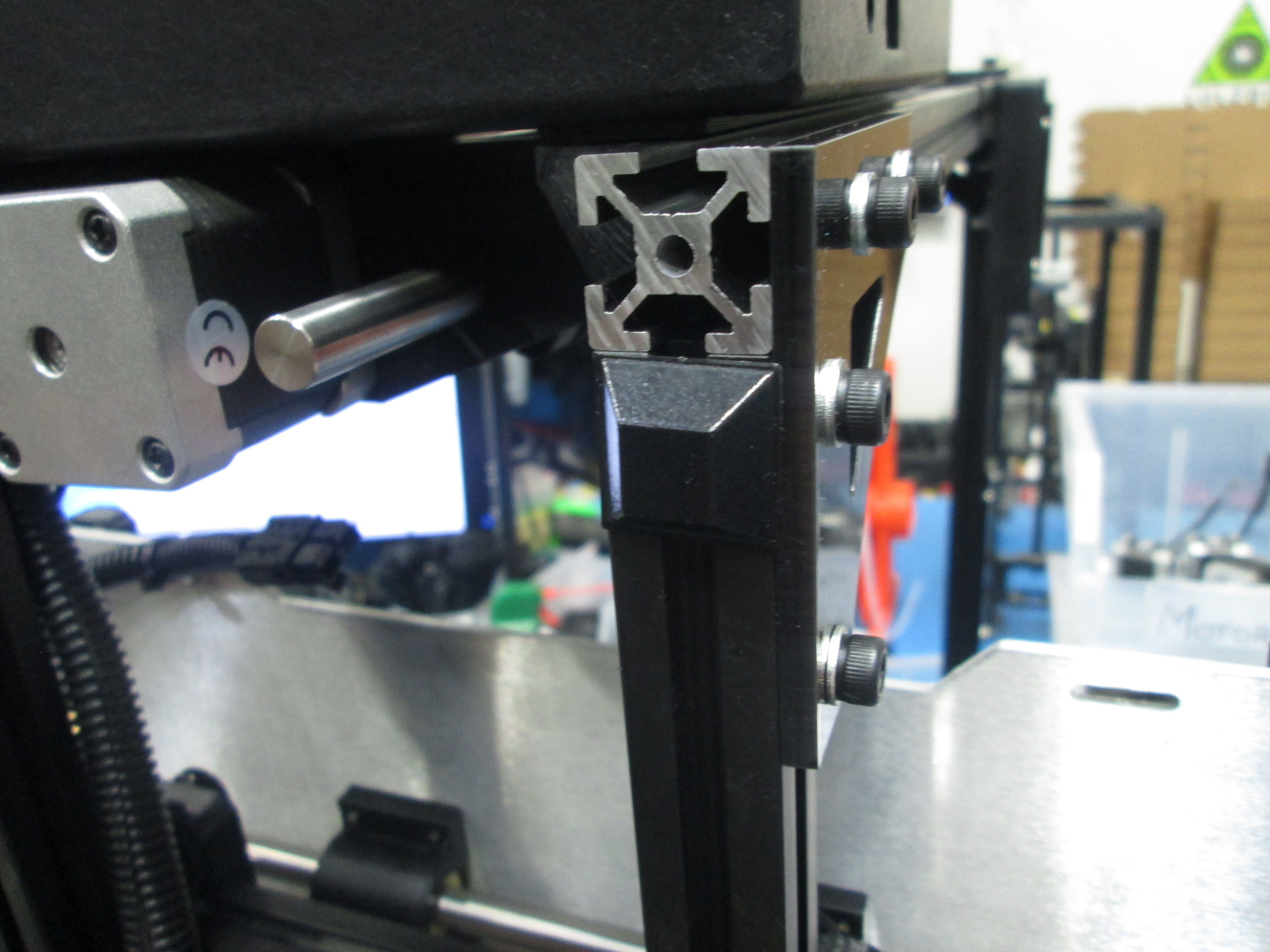
Using 3x M5x14 SHCS and M5 washers and the CB shims, attach the electronics case to the electronics case mounts, make sure to leave out the bottom right bolt for now.
Set the two bottom electronics case mounts flush with the frame. If needed, readjust the top electronics case mounts on the frame.
Loosen Y table mounts and Y mount chassis to allow for adjustment.
Set the 2 left Y mount chassis using the 98 mm fixture as shown.
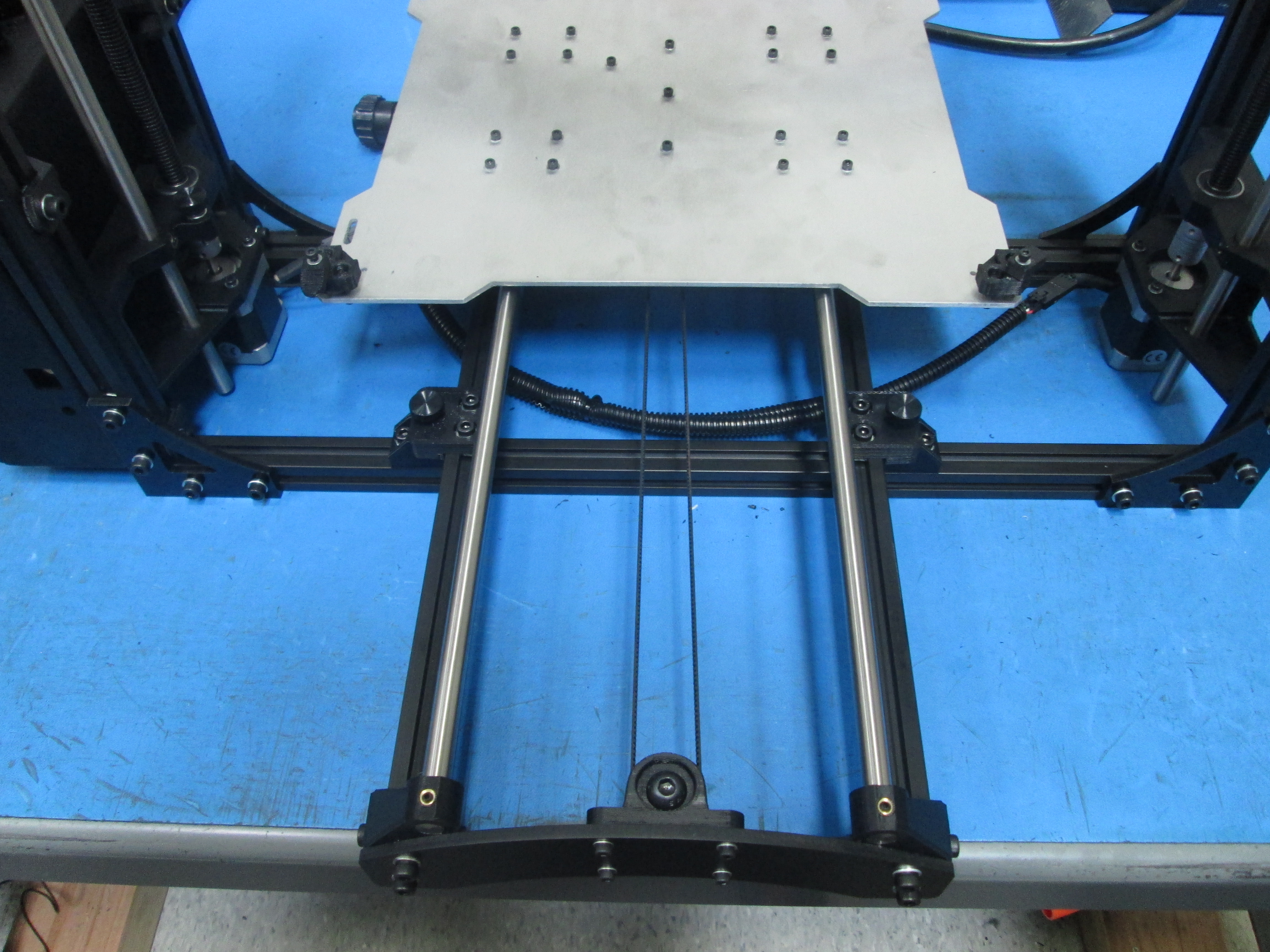
Place Y axis on frame.
Slide the 2 right side Y chassis mounts into the Y table mounts as shown.
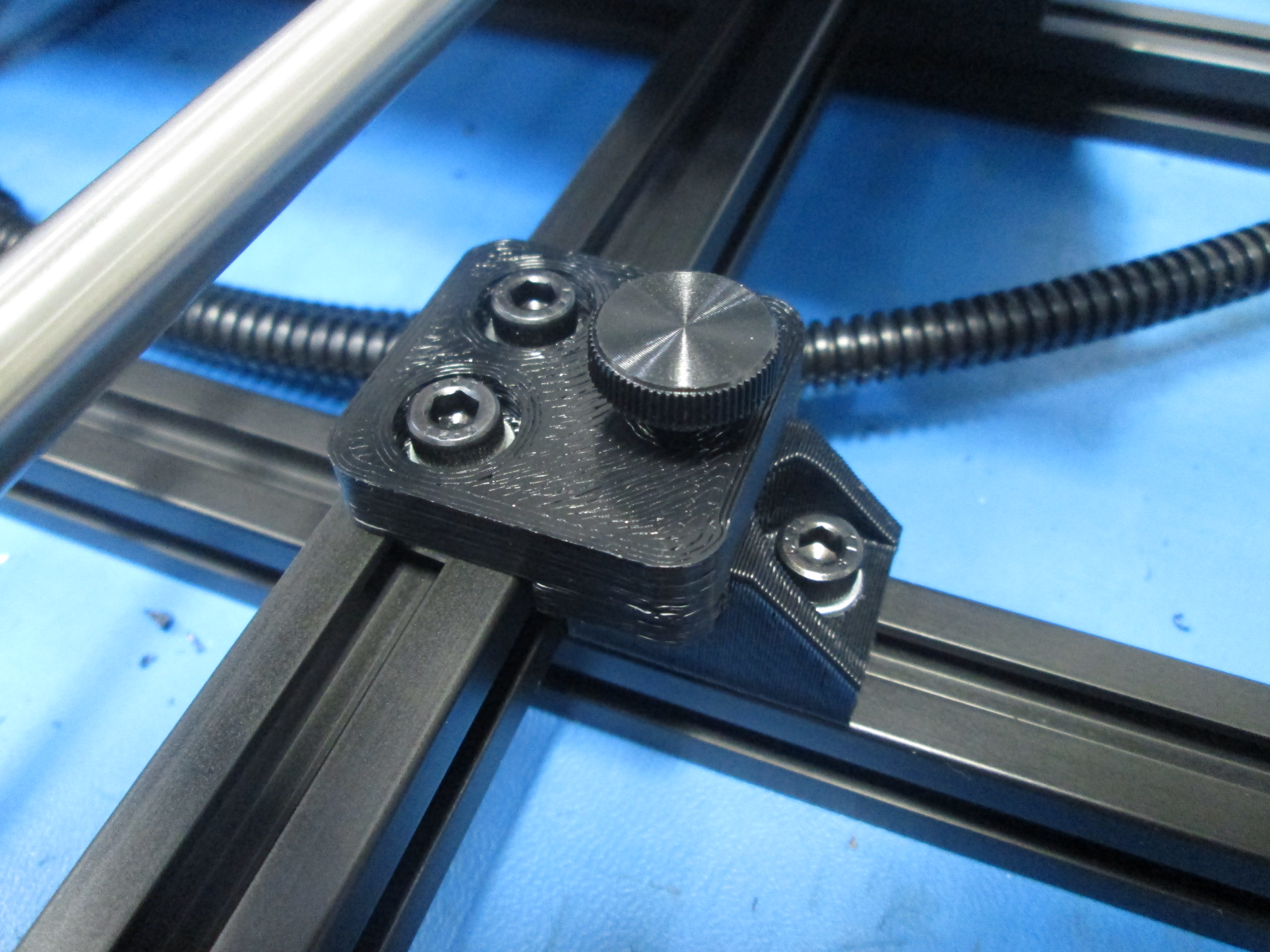
Install 4x M5x14 thumbscrews.
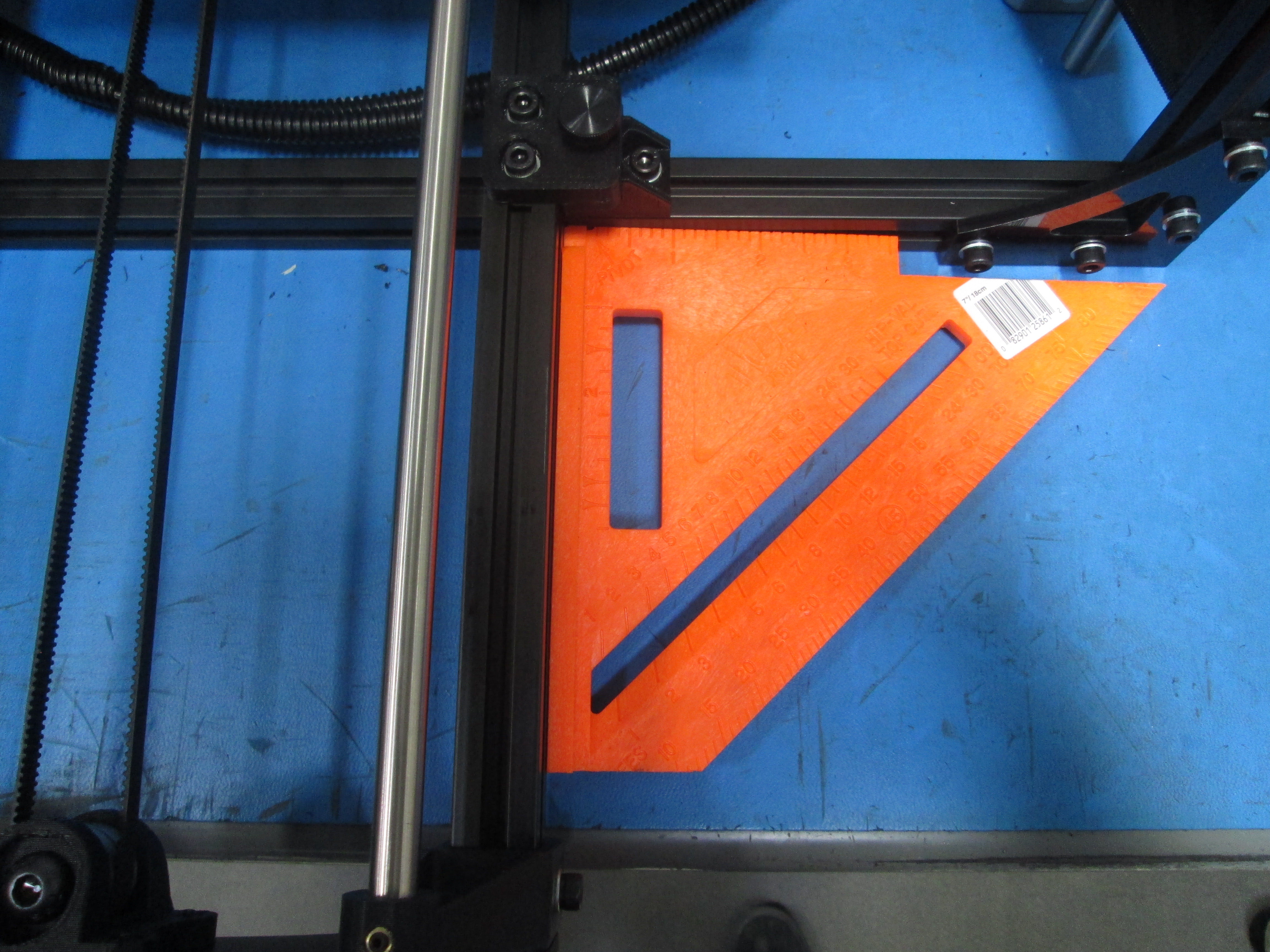
Square Y axis to frame using fixtures and square. Set the Y distance from the frame using the 161 mm fixture as shown.
Tighten Y table mounts, Y mount chassis and thumbscrews.
Make sure Y axis is sitting flush on frame with no gaps in between extrusions.
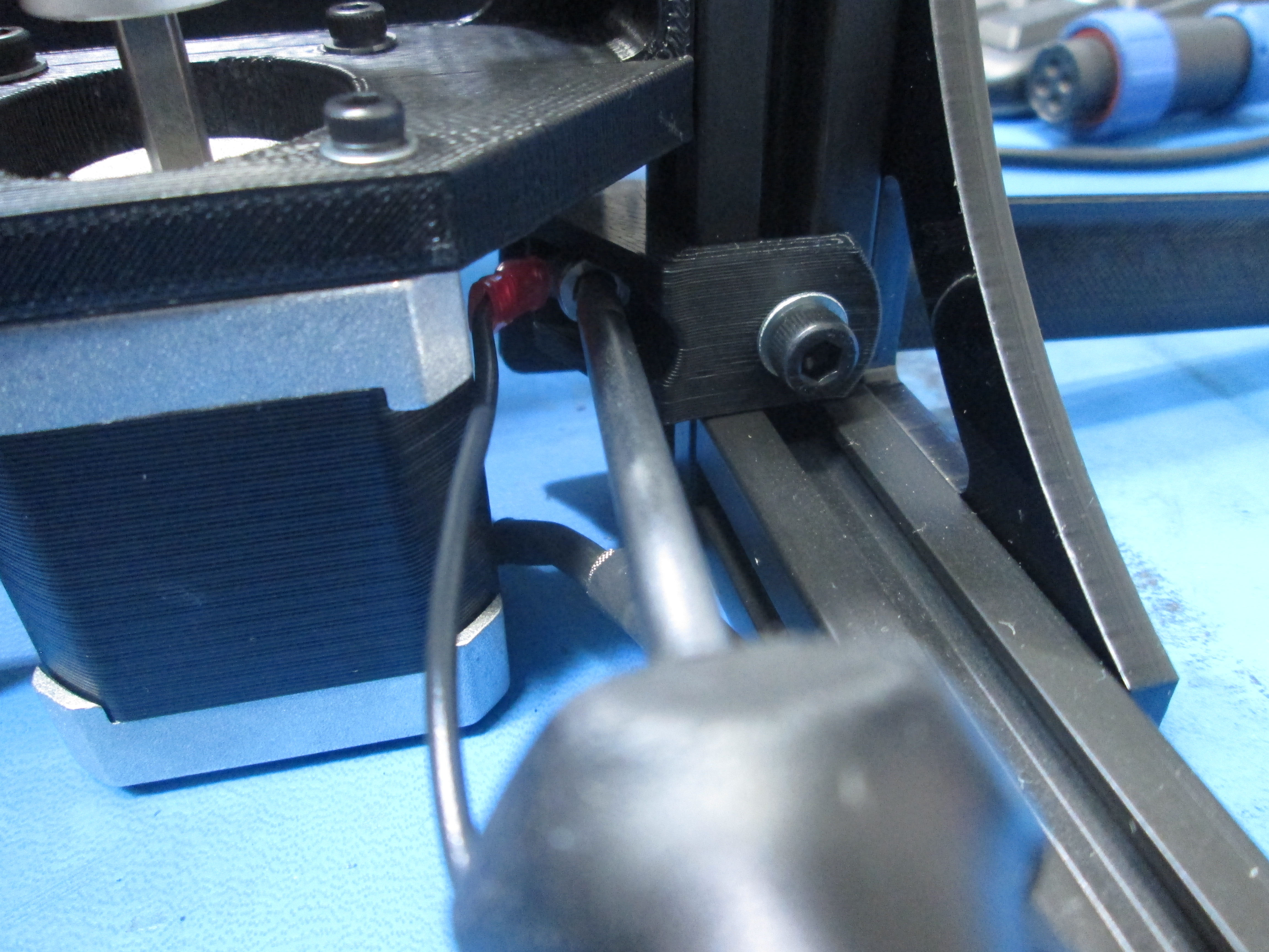
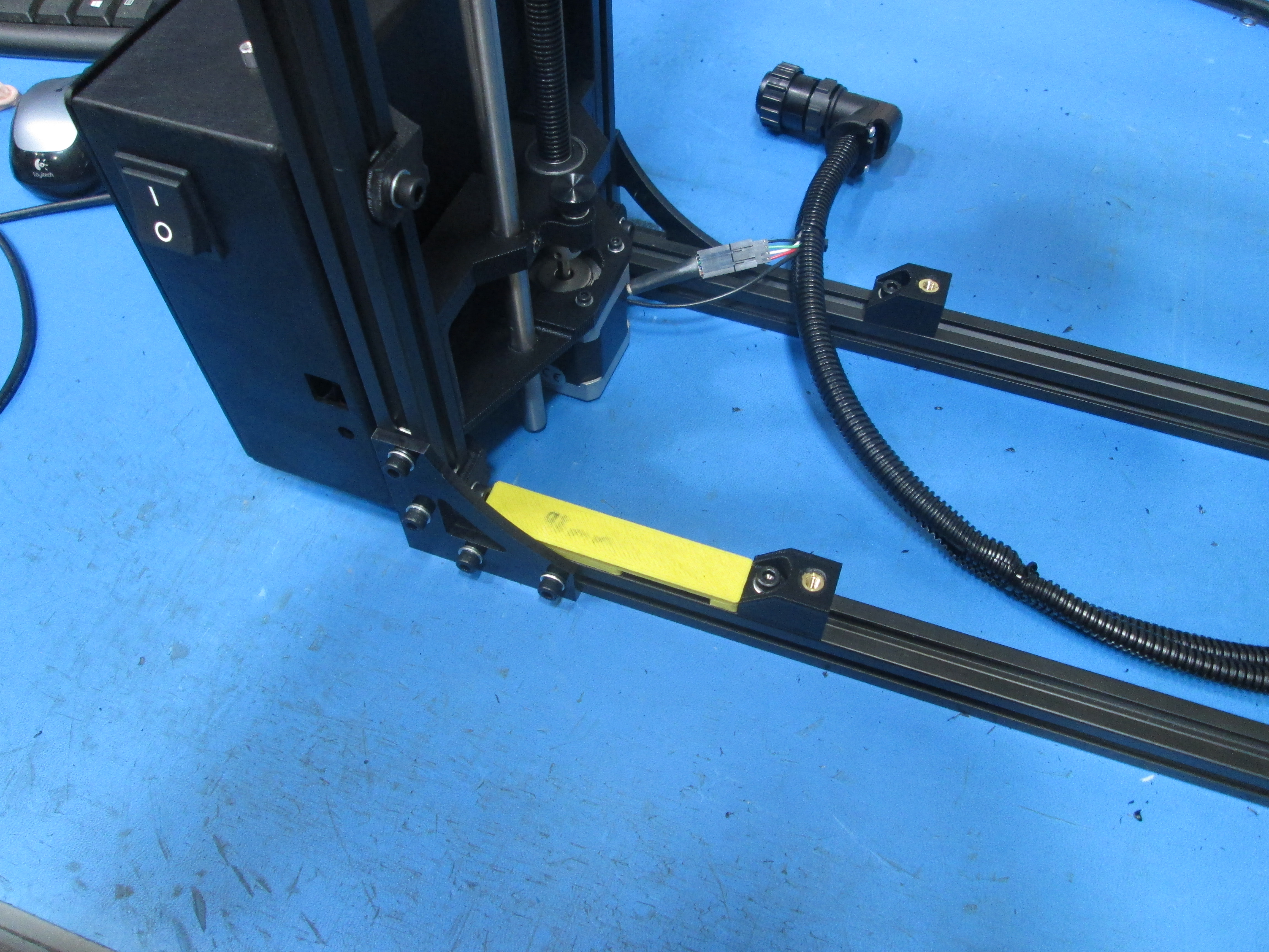
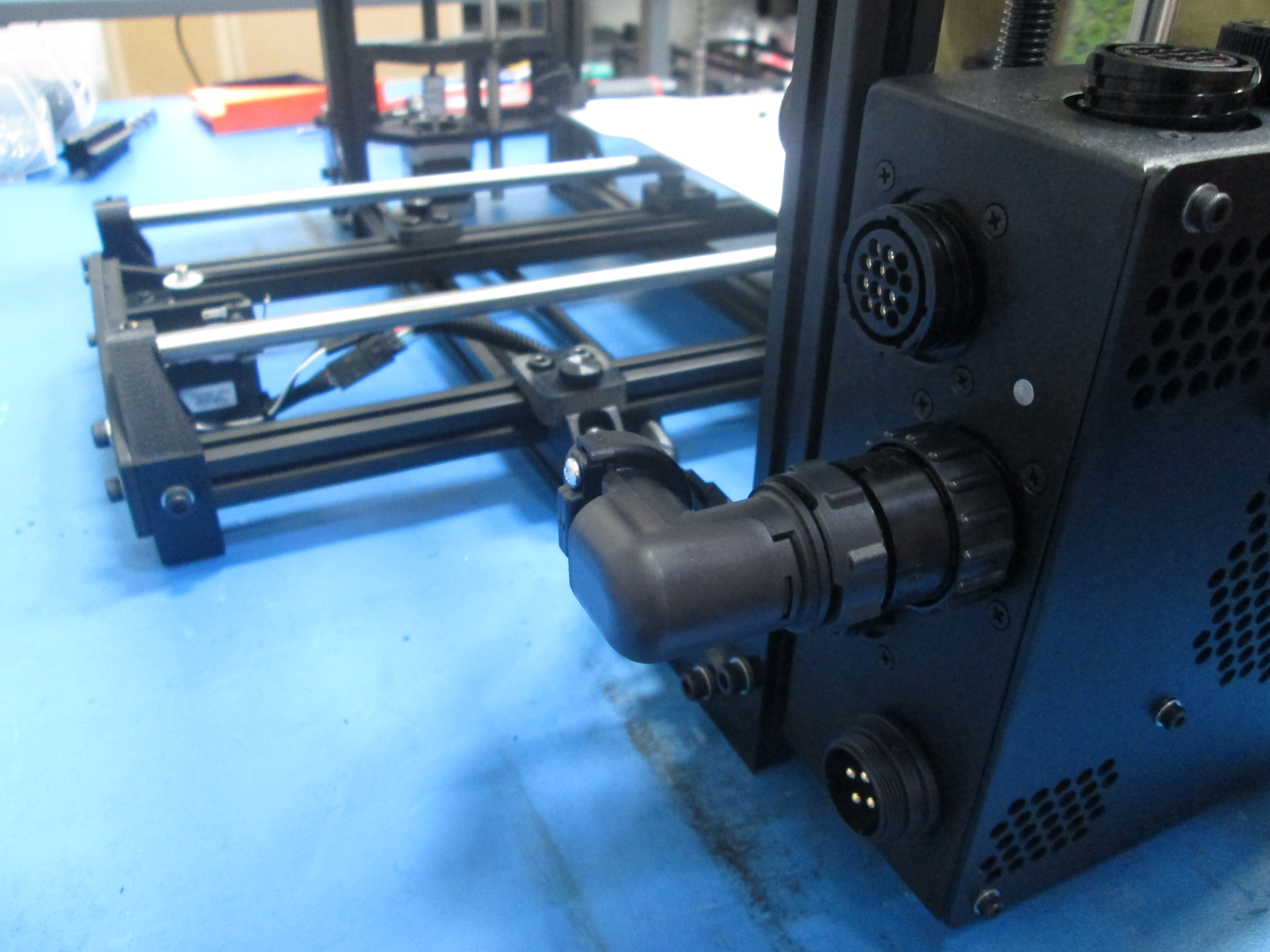
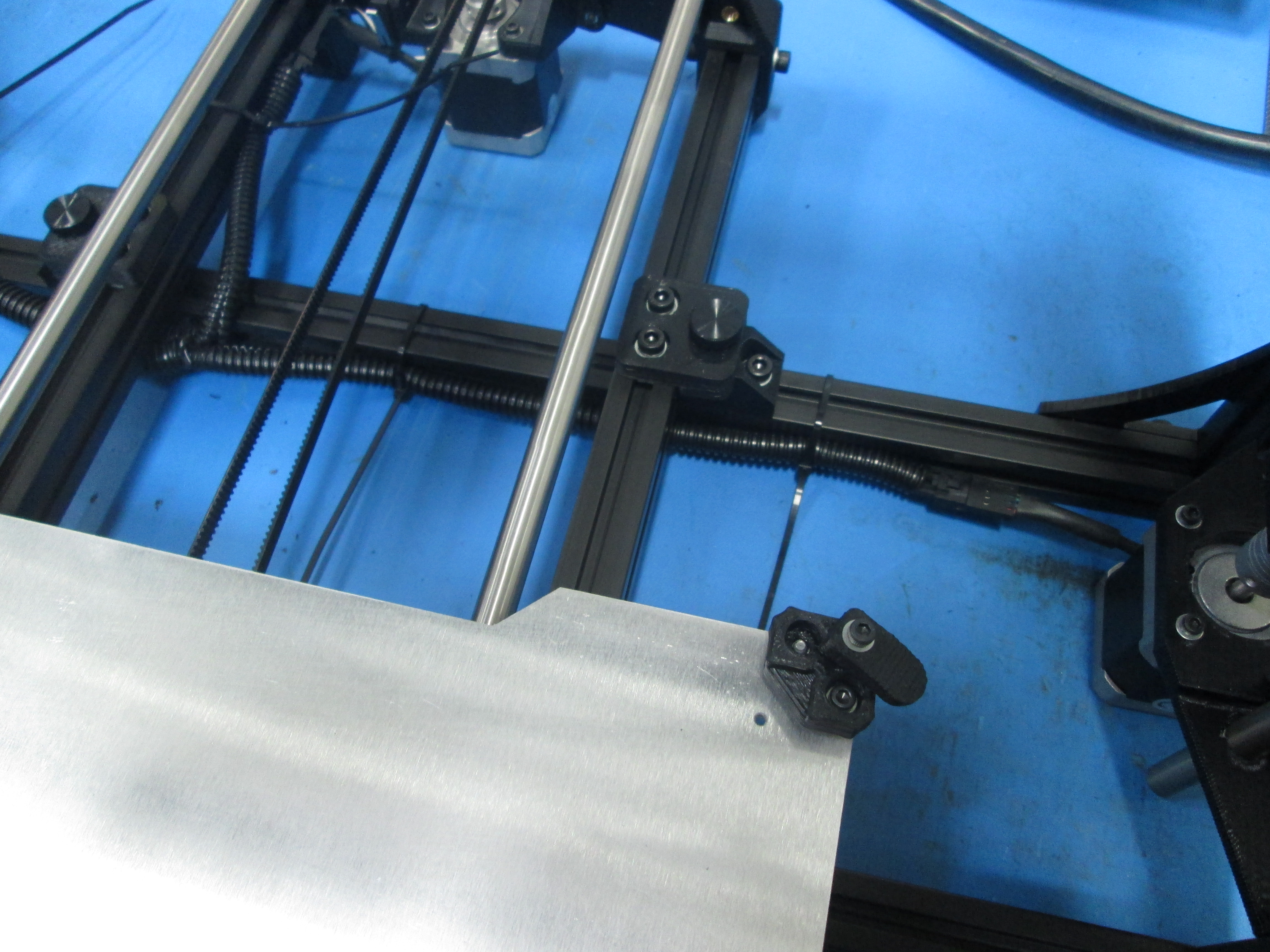
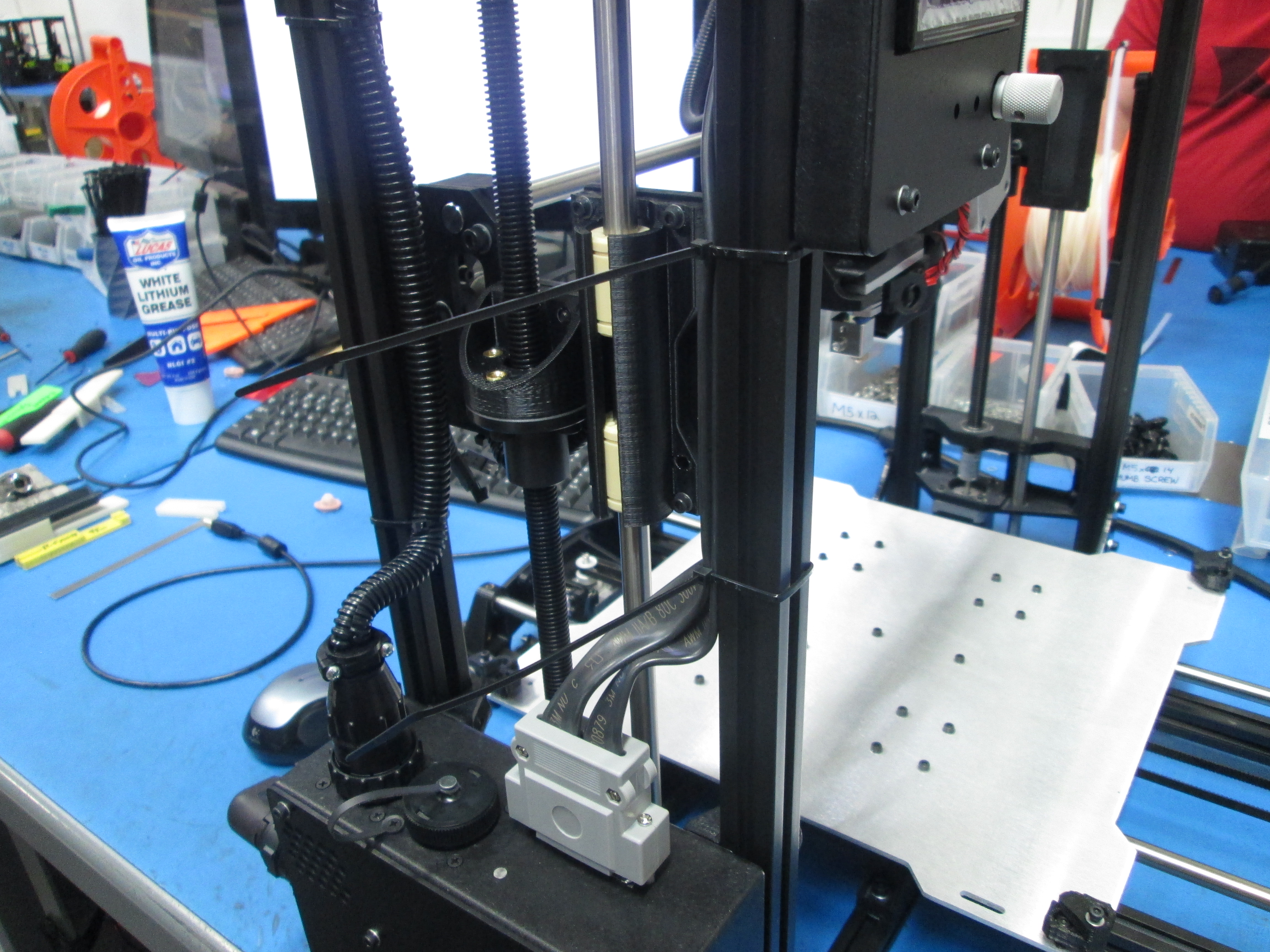
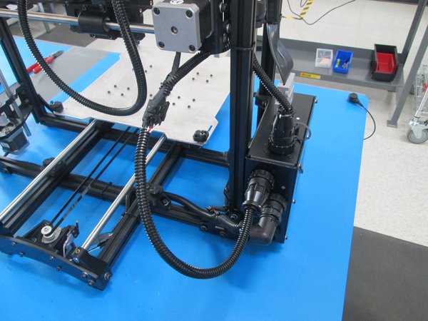
Connect the YZ cable to the Z right motor, Y axis motor and limit switch and fasten the connector to the back of the control box and zip tie in the proper locations as shown.
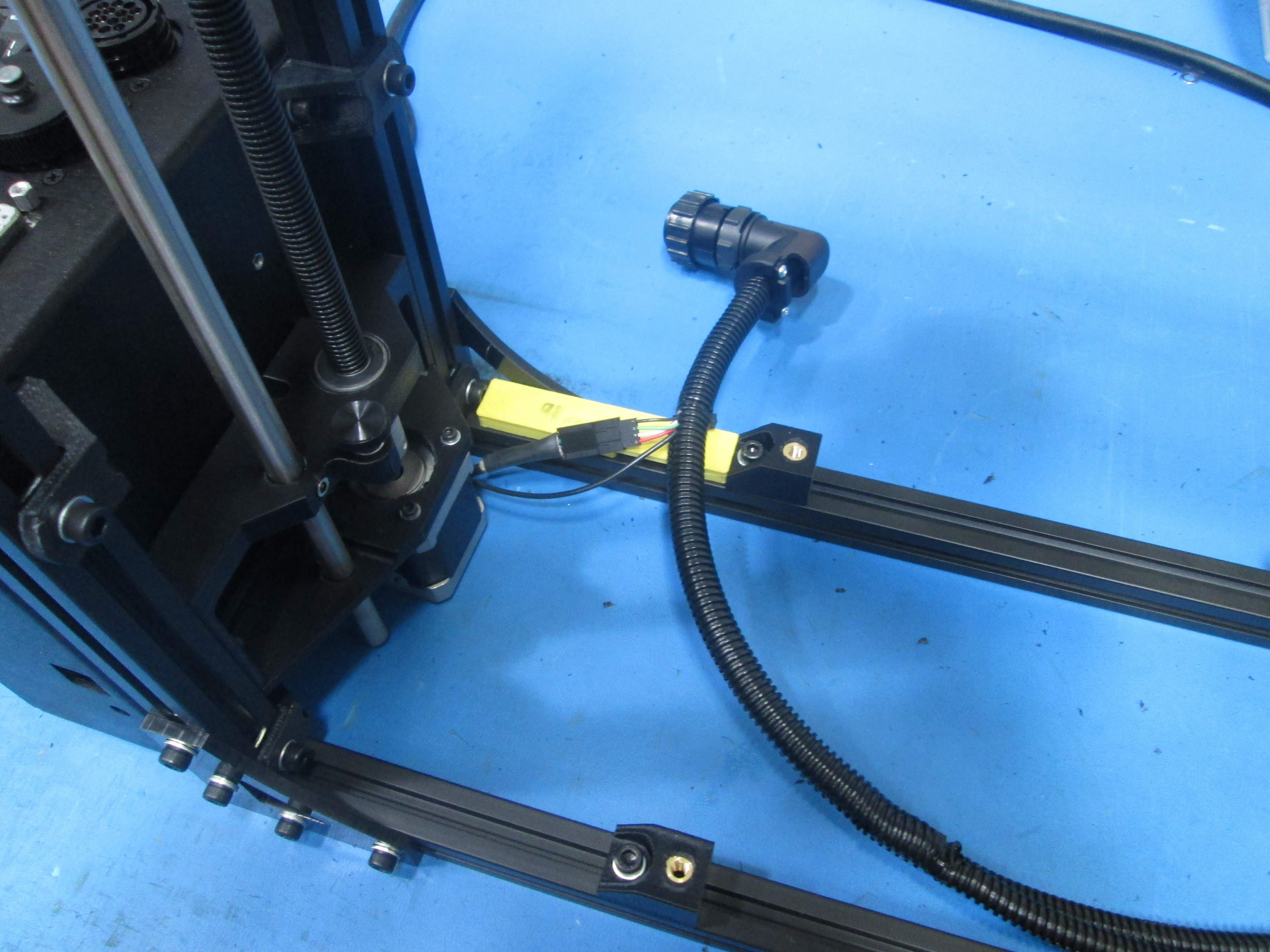

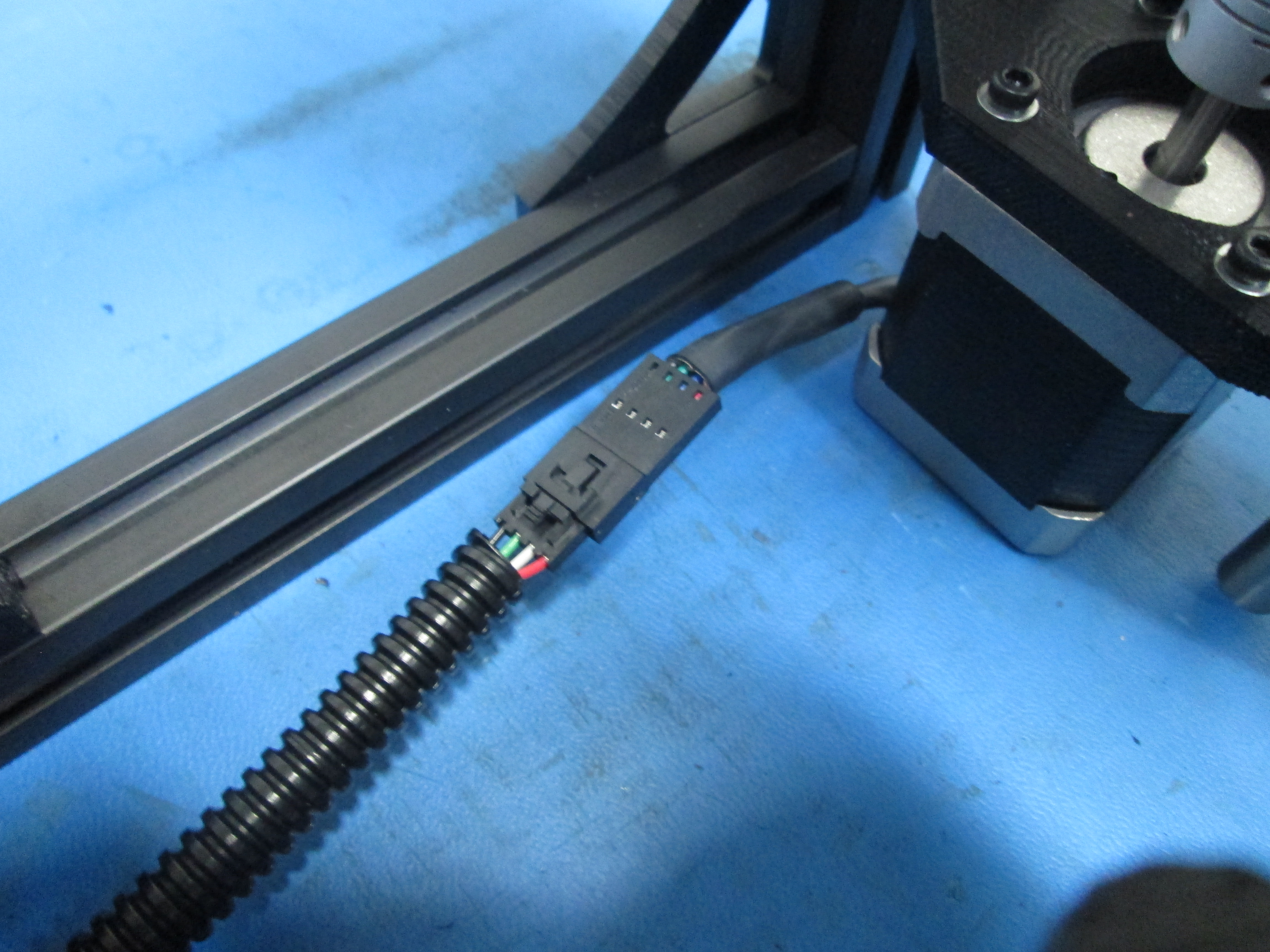
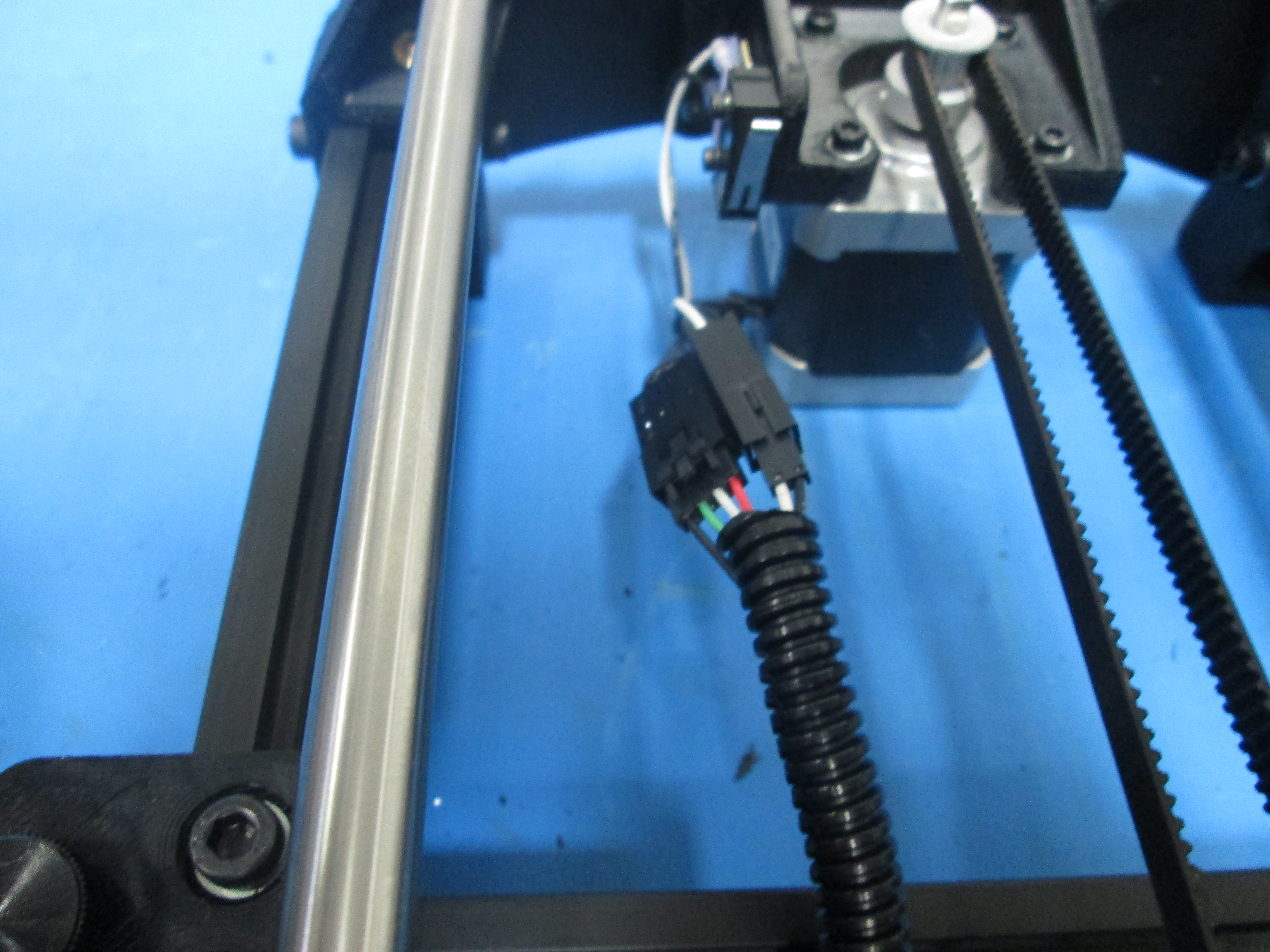
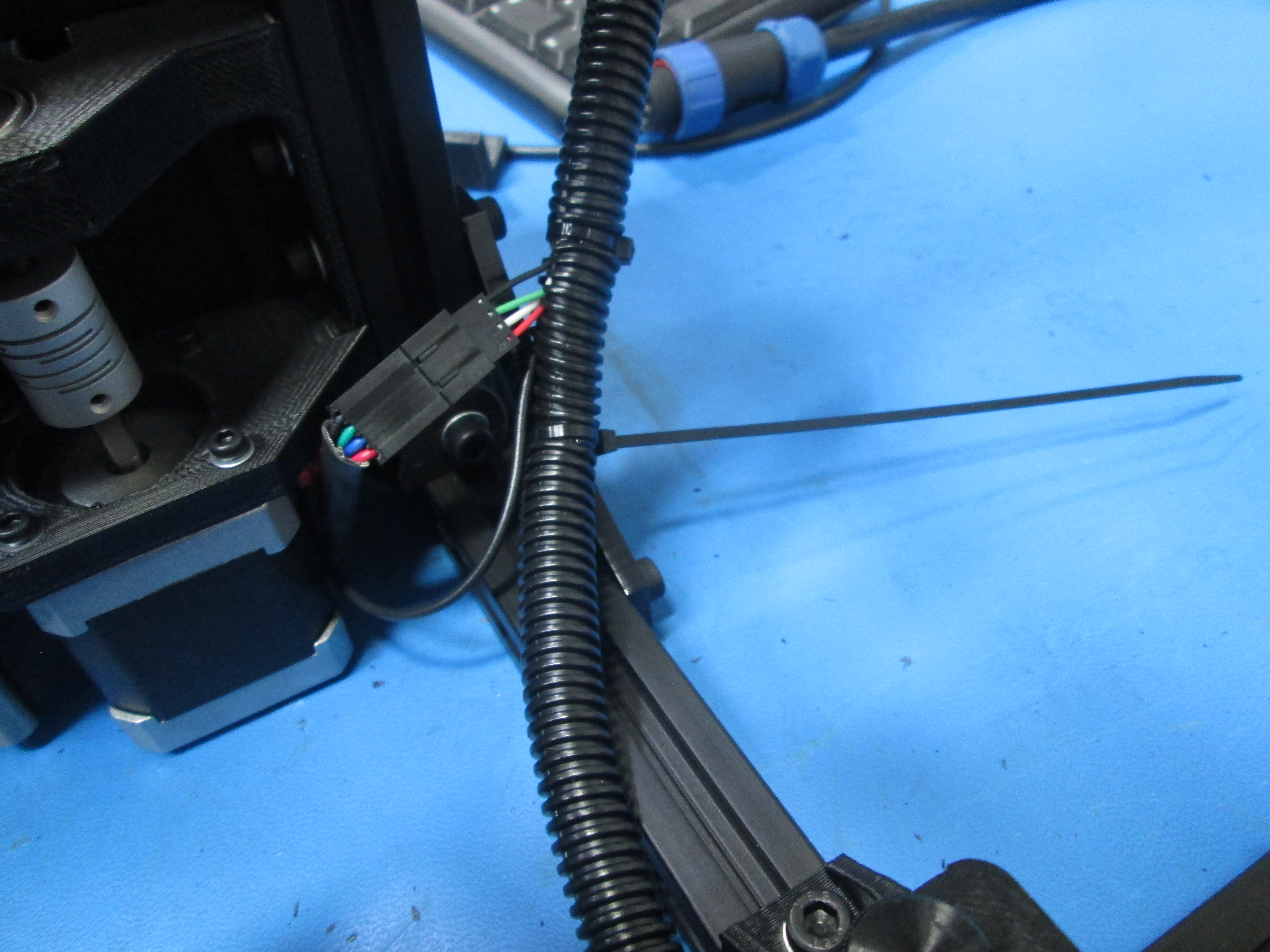
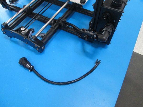
Connect the extruder harness connector to the Extruder #1 connector on the control box as shown.
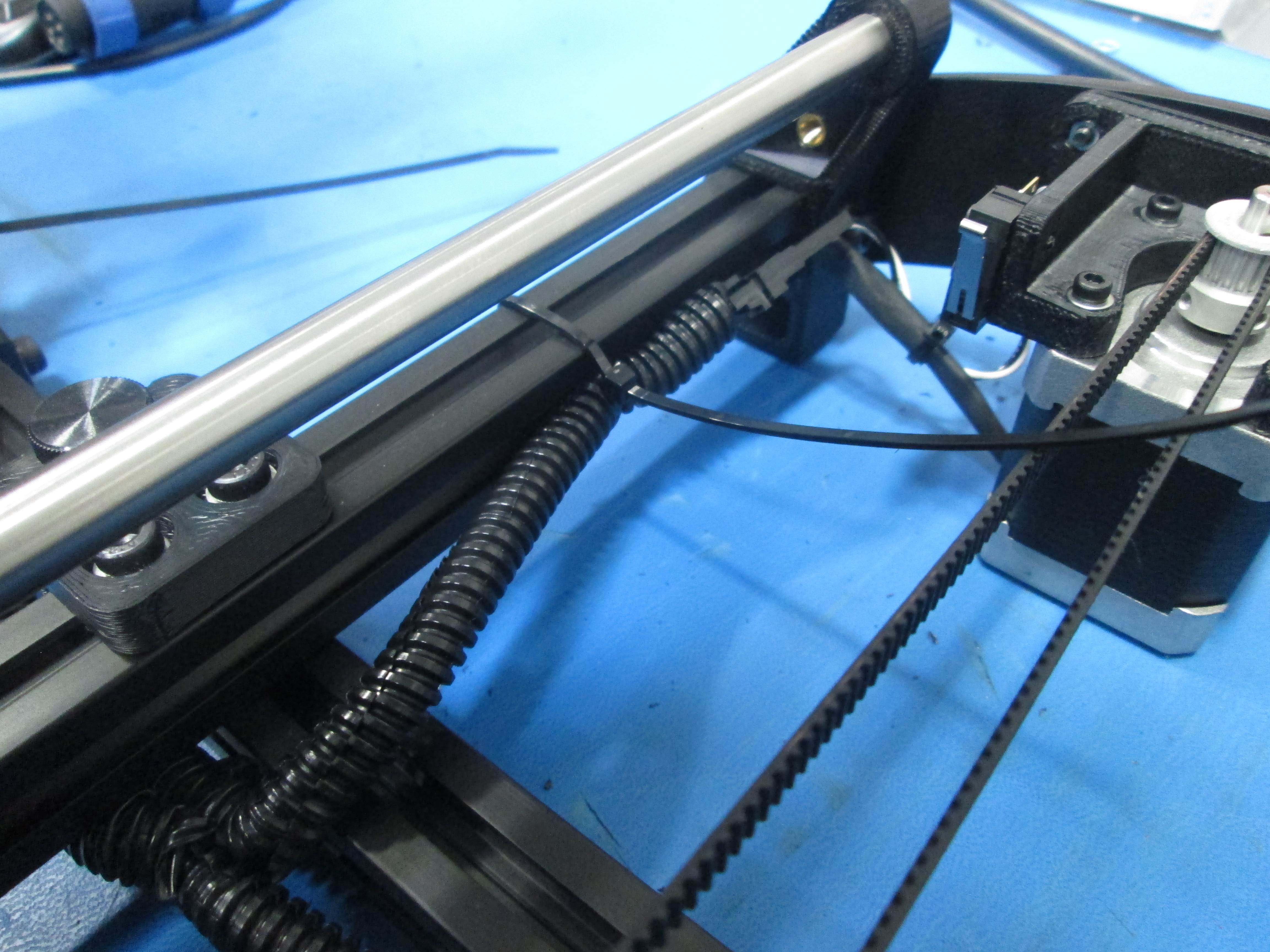
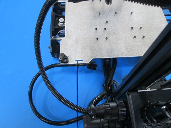
Route harness through the inside of the frame as shown.
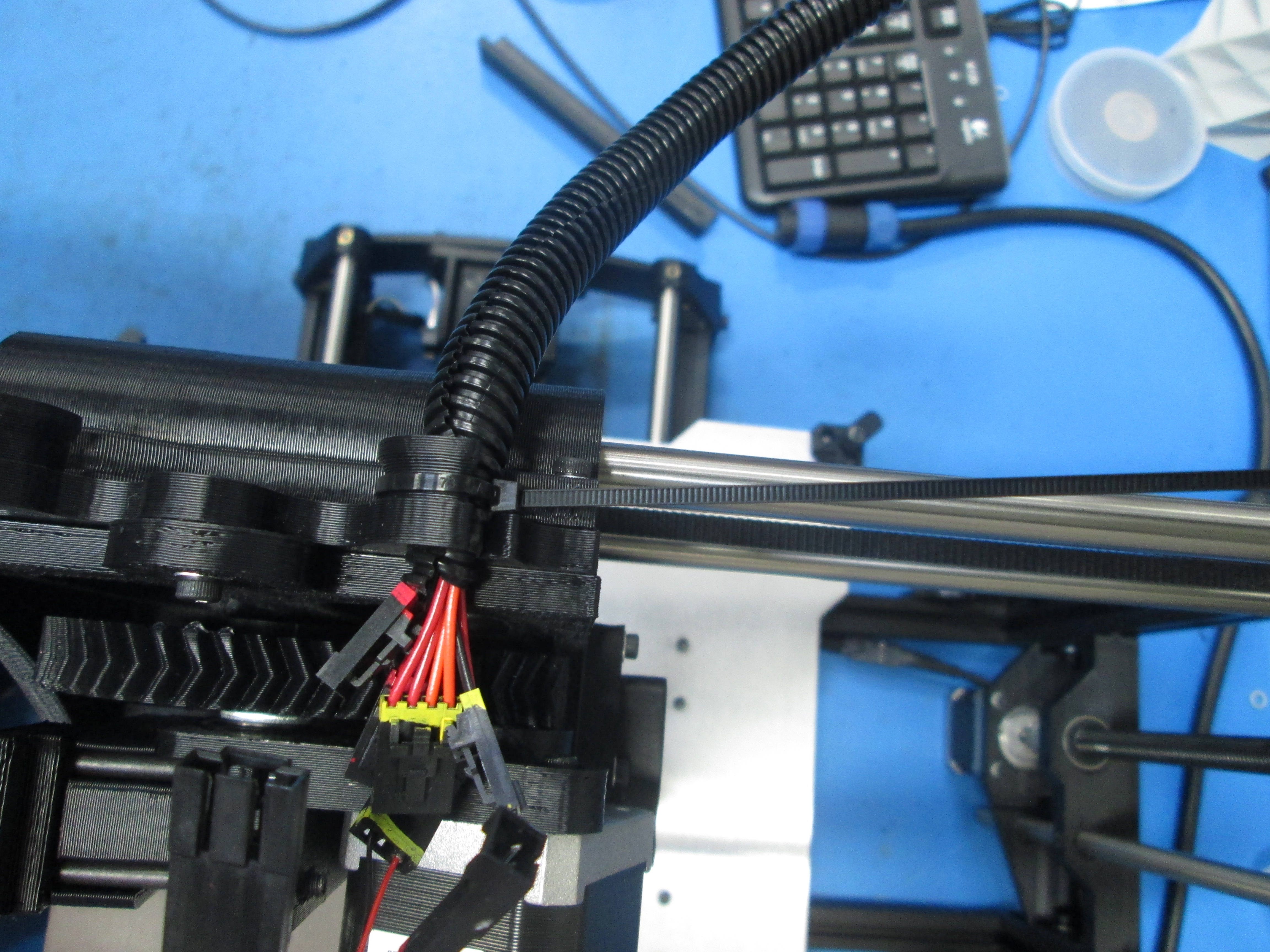
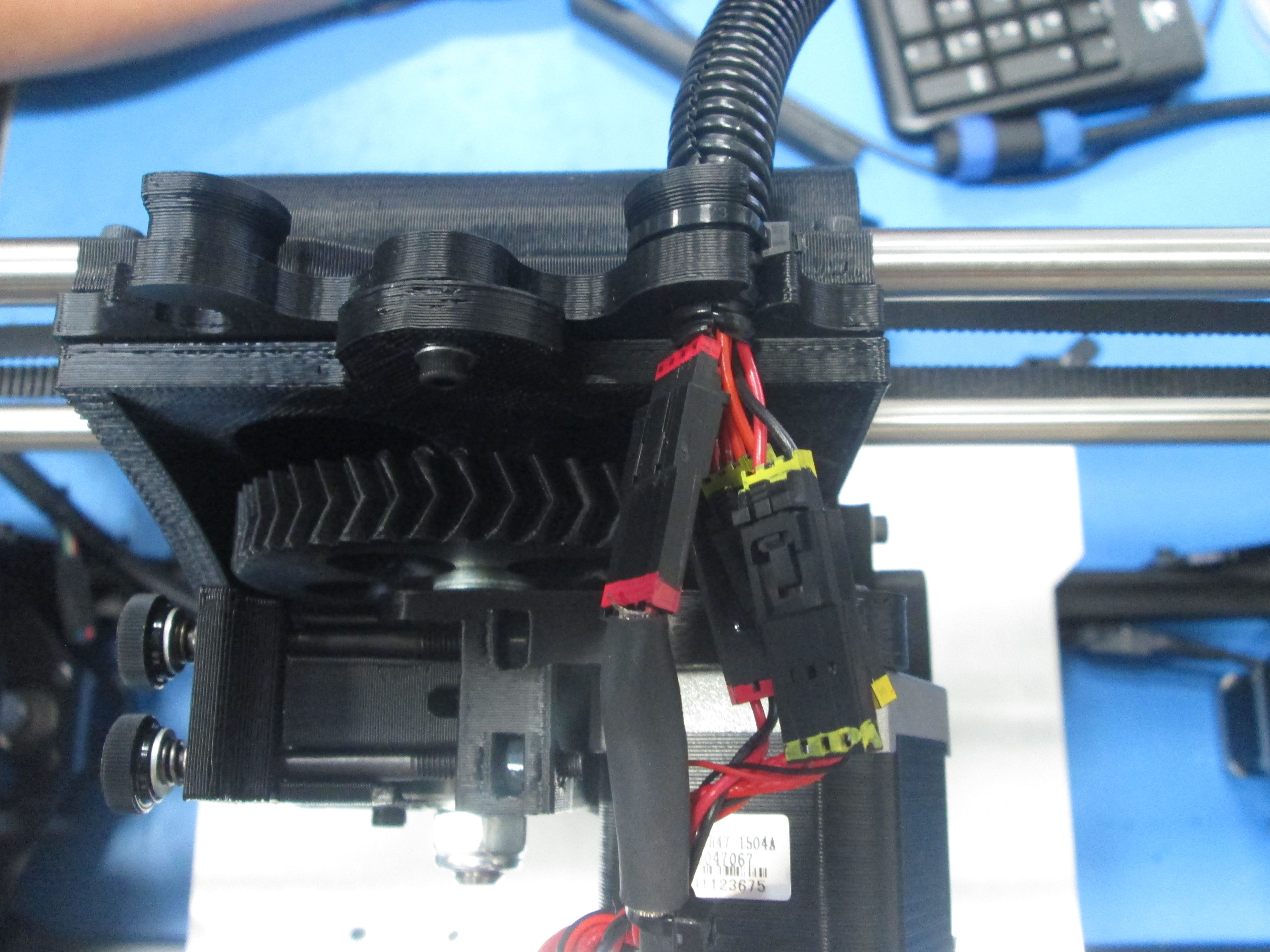
Connect harness to print head and extruder fan wires matching the colors and connectors.
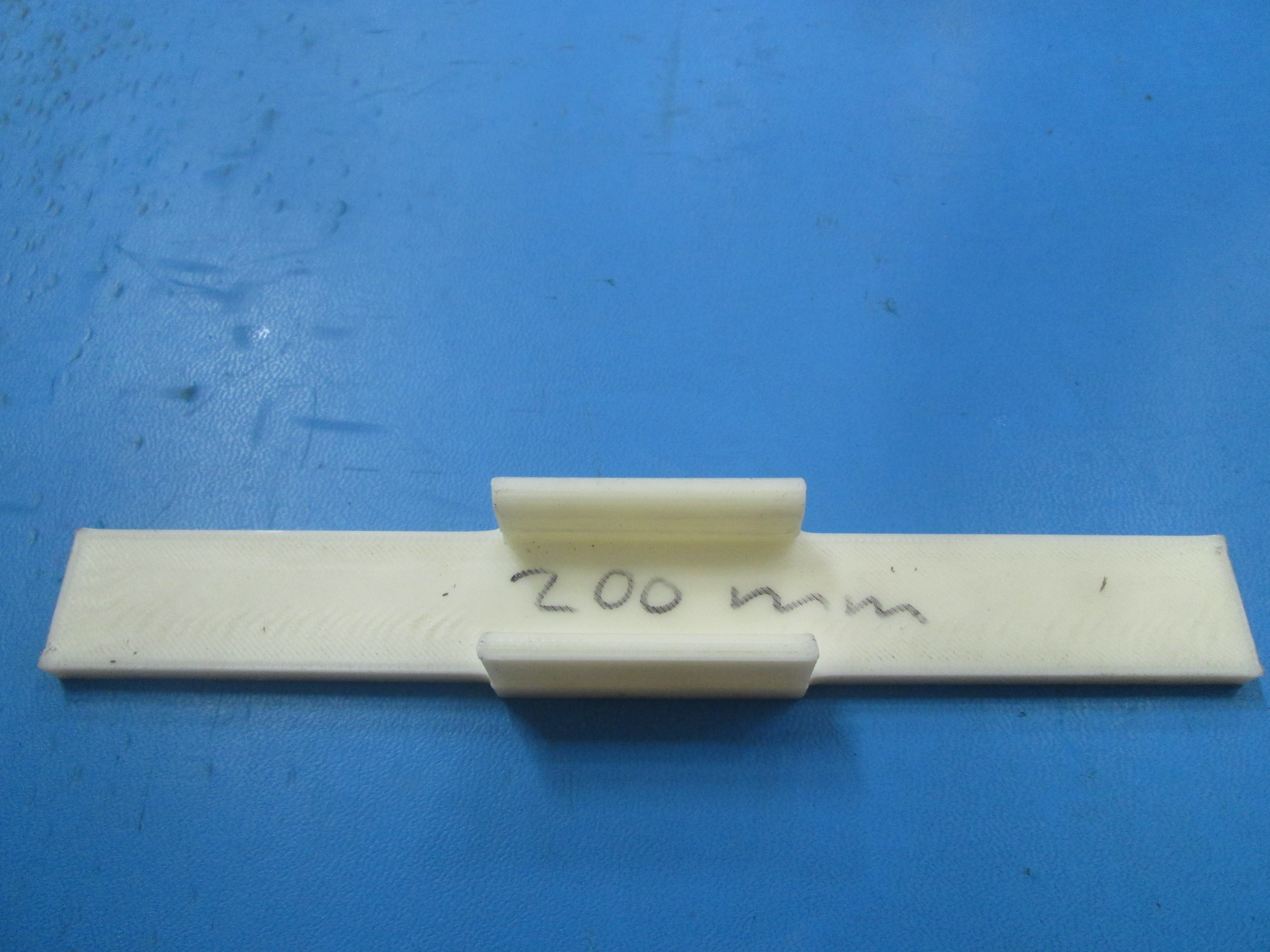
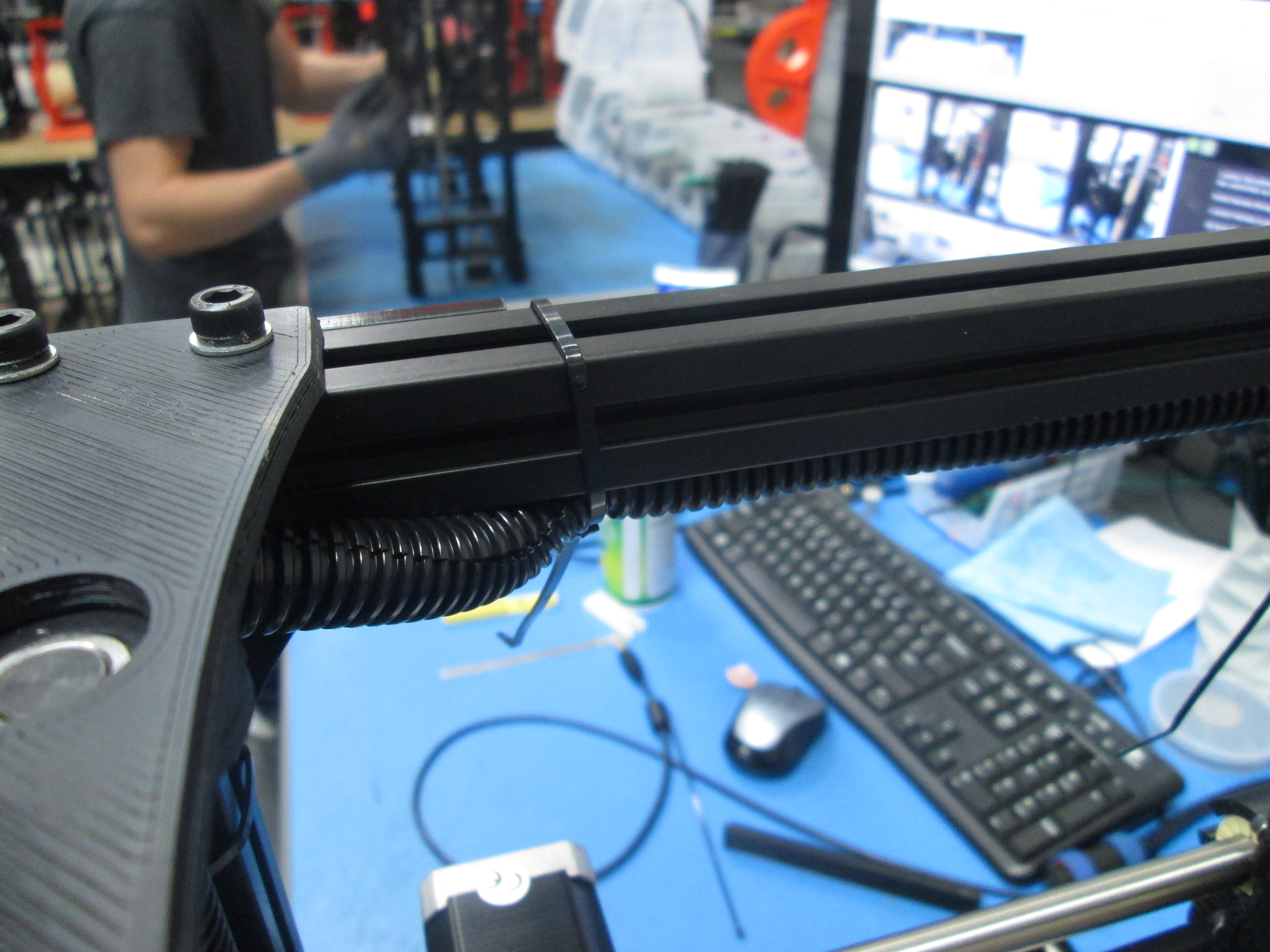
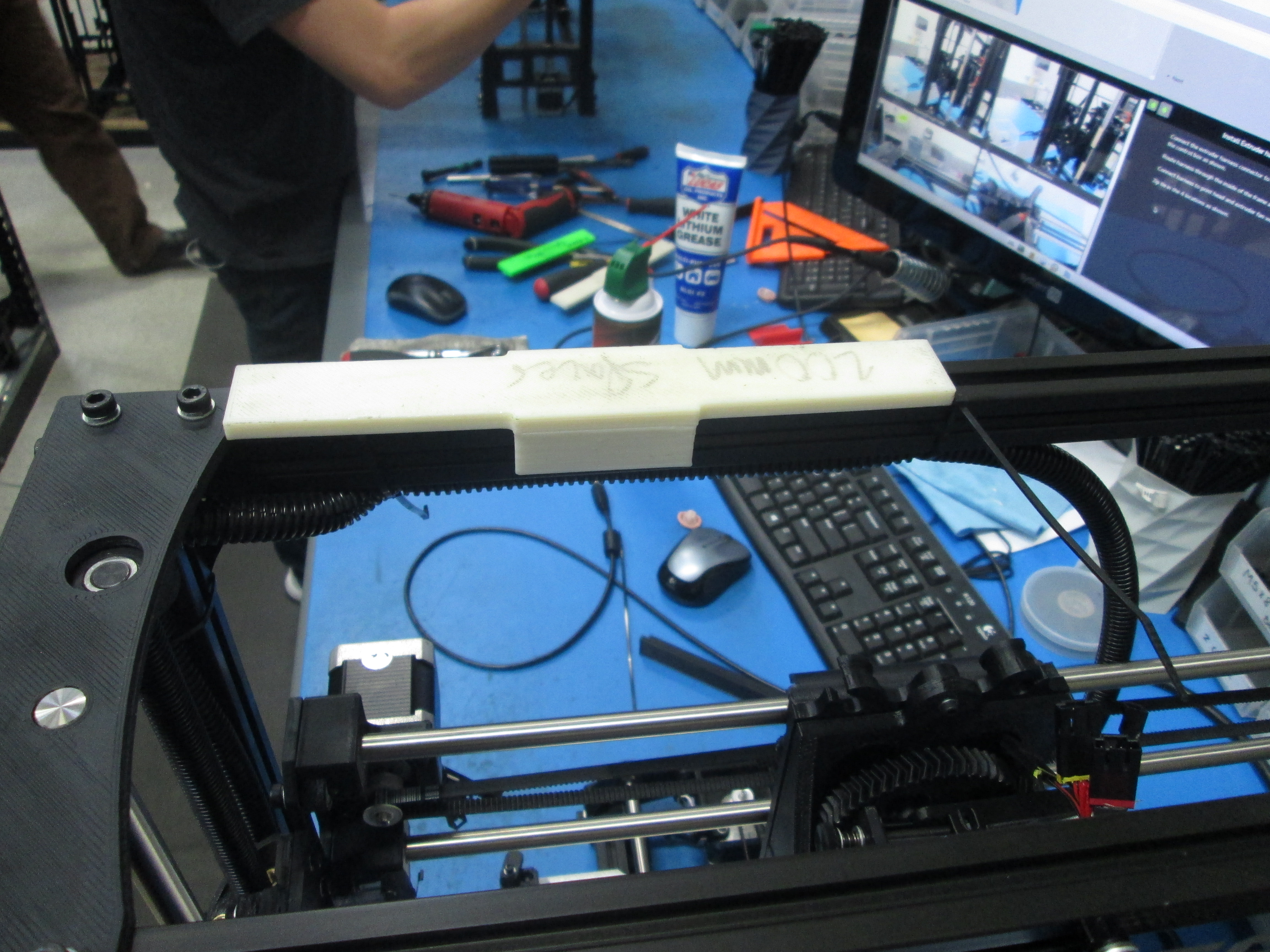
Zip tie in the 5 locations as shown. 2 of the zip ties should be up against the frame connector as shown . Use the 200 mm fixture to set the zip tie in the middle as shown.

Connect the LCD harness to the control box as shown.
Then tighten the Phillips head screws.
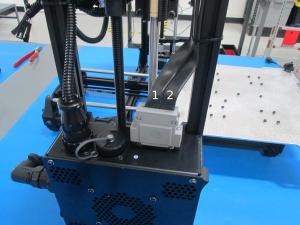
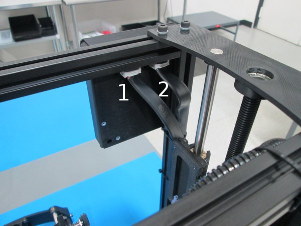
Looking at the back of the LCD, the number one plug is on the left. Plug the number one LCD cable into that left plug. Cables are numbered in picture.
Plug the number two plug into the right side plug on the back of the LCD.
Zip tie in the 2 locations as shown. Route the #1 cable over the #2 cable making sure they are nice and neat looking.

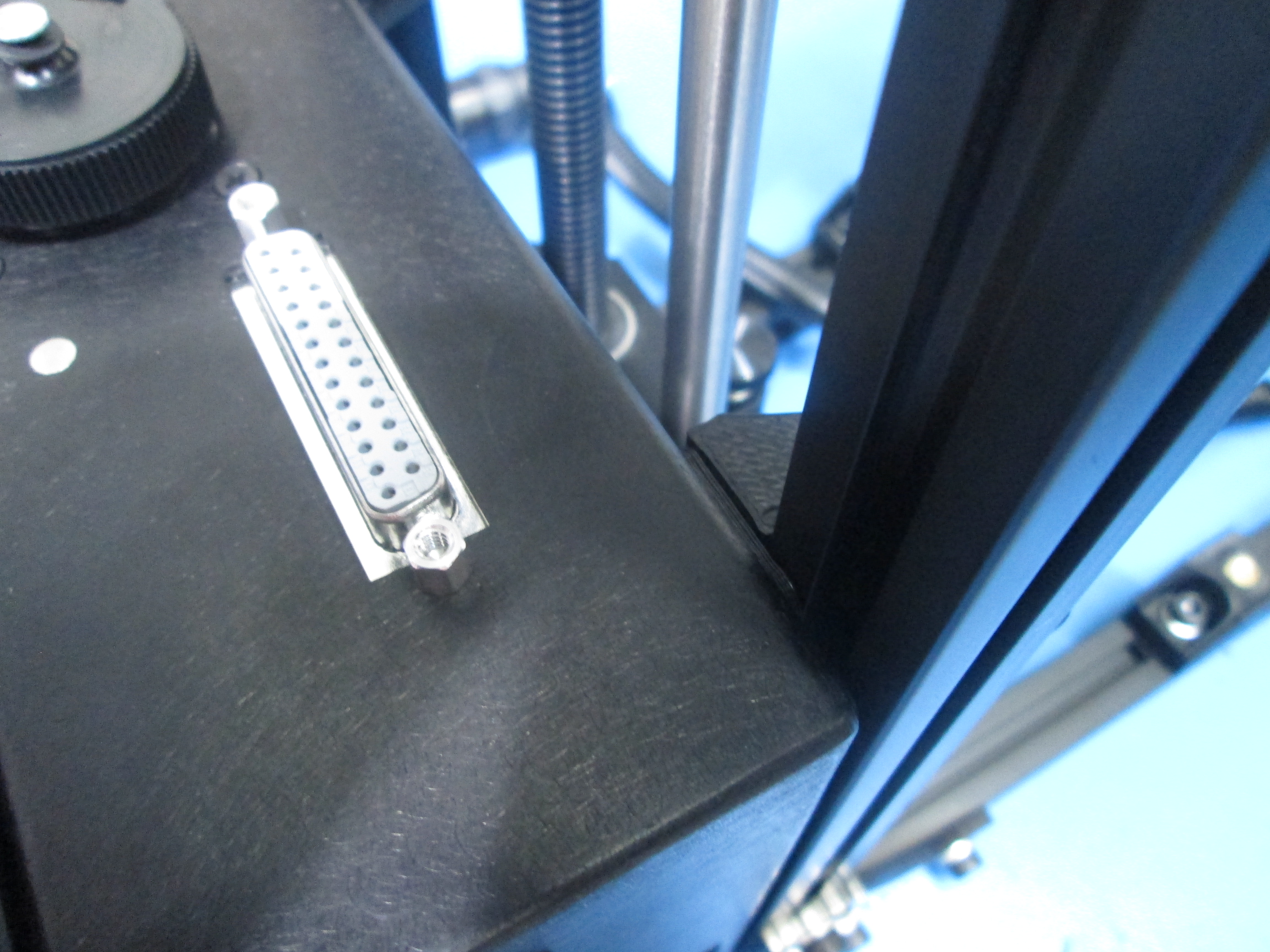
Connect the XZ harness to the top connector on the back of the control box as shown.
Connect the other end of the XZ harness into the X motor and matching limit switch wires as shown.
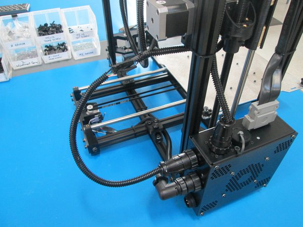
Connect the heat bed harness to the 3rd connector down on the back of the control box as shown.
Route the heat bed harness around the back of the frame and zip tie the other end to the Y axis plate as shown.

Install 8x rubber feet to bottom of frame and Y axis.
Take note of location, do not cover bottom of vertical extrusion.
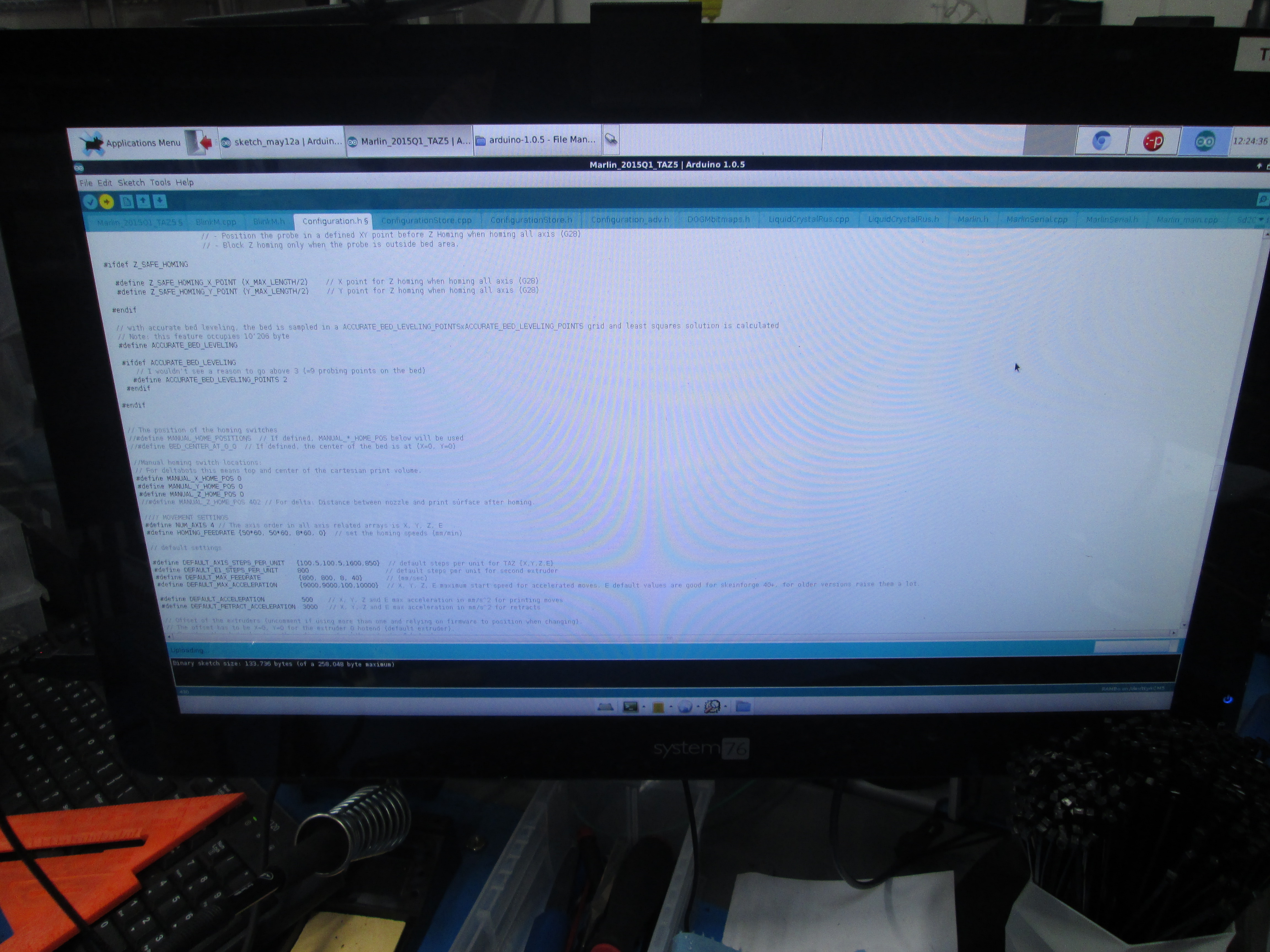
Flash the firmware through Arduino.
Open Arduino. Select the current firmware File>Sketchbook > Marlin > Marlin_2015Q1_Taz5.
Upload.
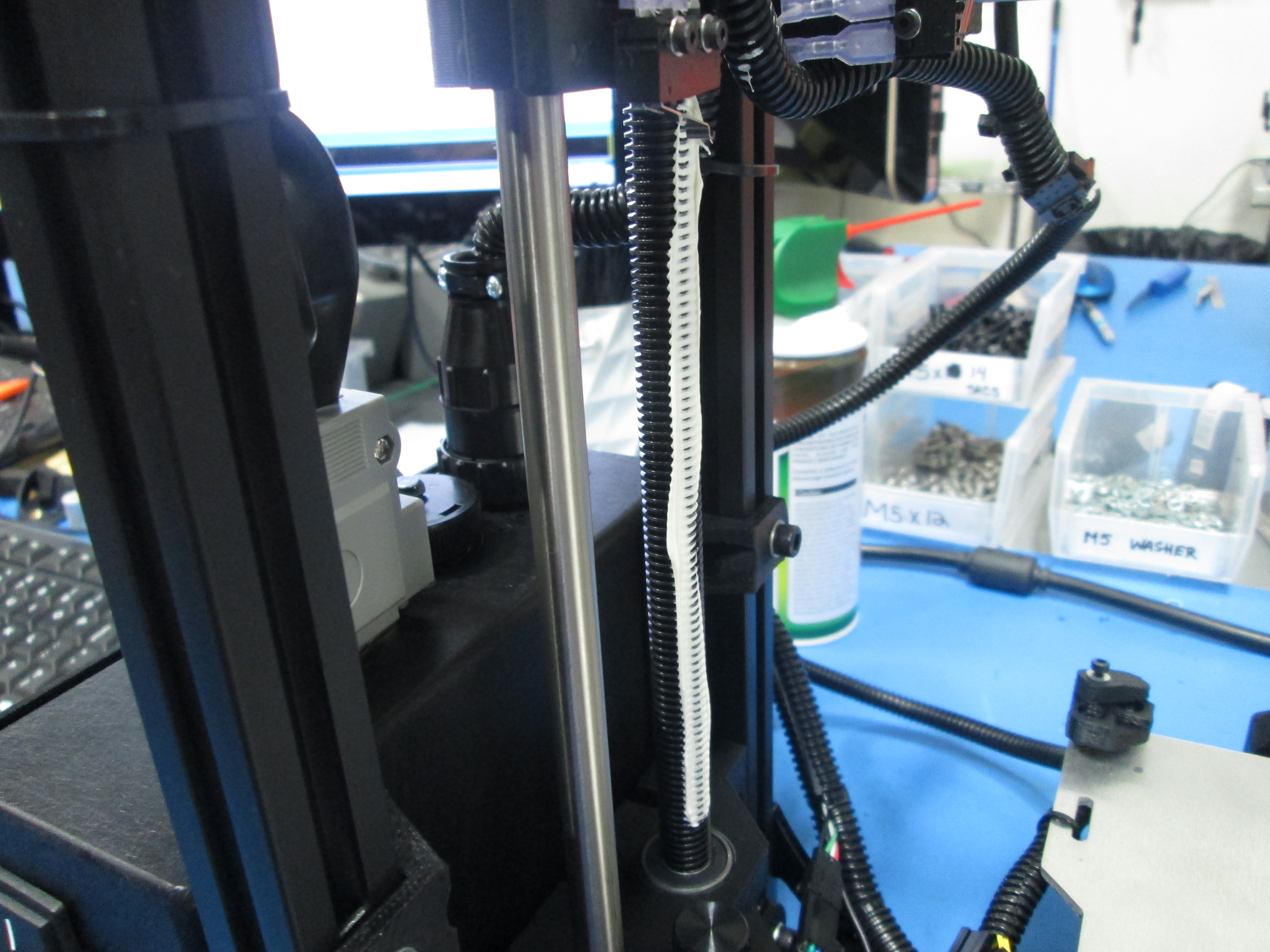
Next, using an SD card, run the Z Burnin Gcode and grease the drive rods using white lithium grease. Only grease the areas where the rods travels. Clean up the excess grease once it has made a few passes up and down.