Open HardwareAssembly Instructions
Guides for installation and assembly of the LulzBot line of products made by FAME 3D LLC.
Guides for installation and assembly of the LulzBot line of products made by FAME 3D LLC.
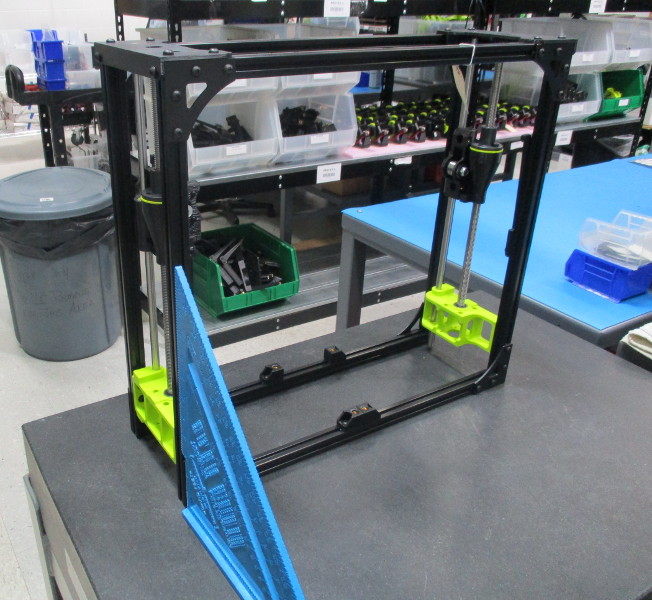
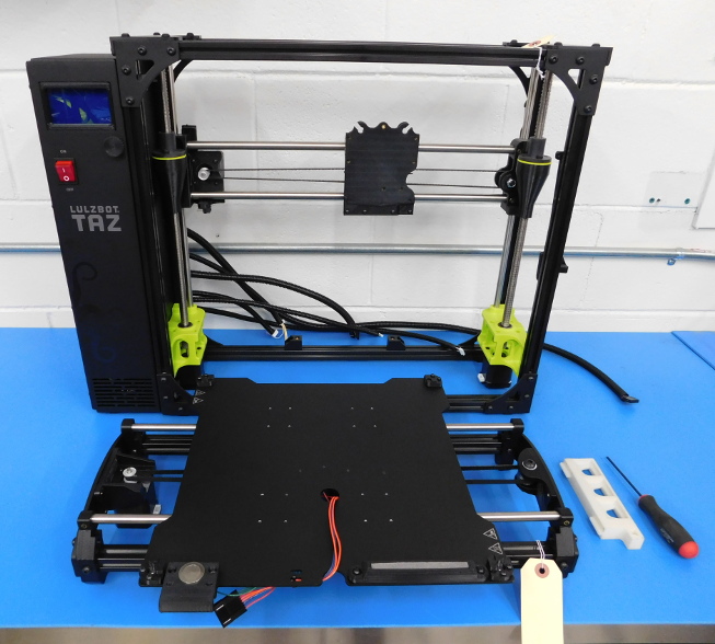
Obtain a completed TAZ6 Frame Assembly (AS-PR0006)
Place the completed frame on the granite block and verify that it sits flat and and doesn’t teeter, like a chair with one short leg.
Line up the square along both ends, perpendicular to the length of the frame, as pictured.
Examine the relationship between frame and square. If at any point the gap meets or exceeds 2mm, the frame must be rejected for re-squaring.
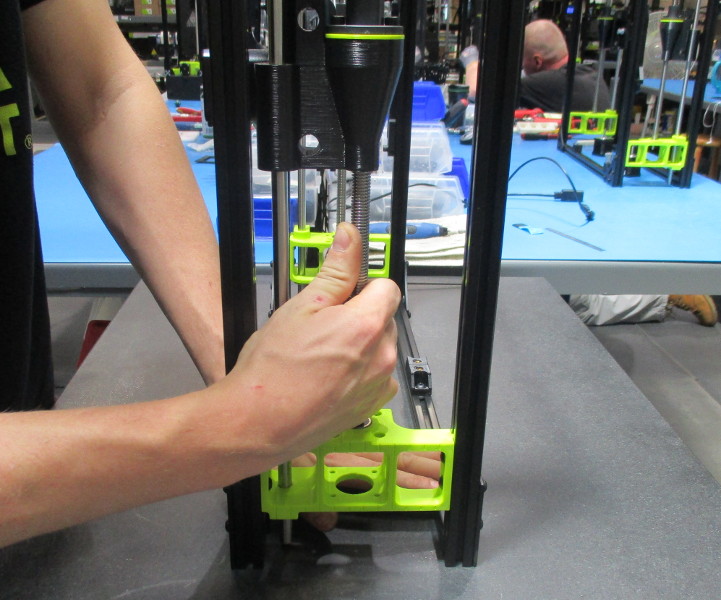
Firmly grasp each drive rod and check for movement between the upper and lower bearings by attempting to move the drive rod up or down. Both drive rods must be incapable of vertical movement. Visually verify that the drive rod has been fully seated in both bearings.
If any vertical movement is possible (without flexing the Z-Upper) or the bearing is not fully seated, the frame must be rejected.
The frame must be re-squared after proper tension is achieved.
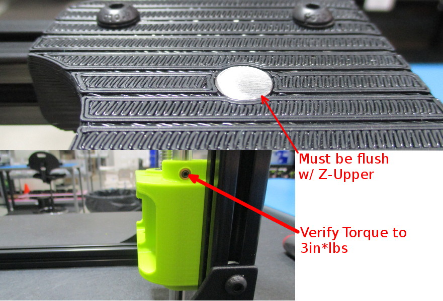
Verify that the vertical smooth rods are flush with the Z-Upper and that the set screws in the Z-Lowers have been torqued to 3 in*lbs.
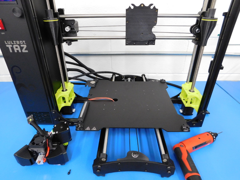
If all criteria have been met, carefully place the frame on your workbench.


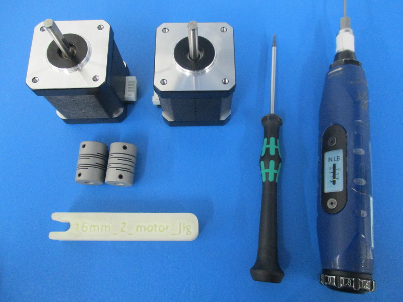
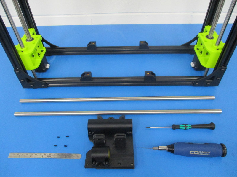
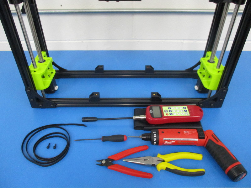
Gather parts:
2x NEMA 17 Stepper Motor, Moons' - EL-MT0029
2x Helical Flexible Shaft Coupling with Set Screws HD-MS0351
Required Tools:
1.5mm Hex Driver
16mm Z-Motor Jig
5in*lbs Torque Driver w/ 1.5mm Hex Bit installed
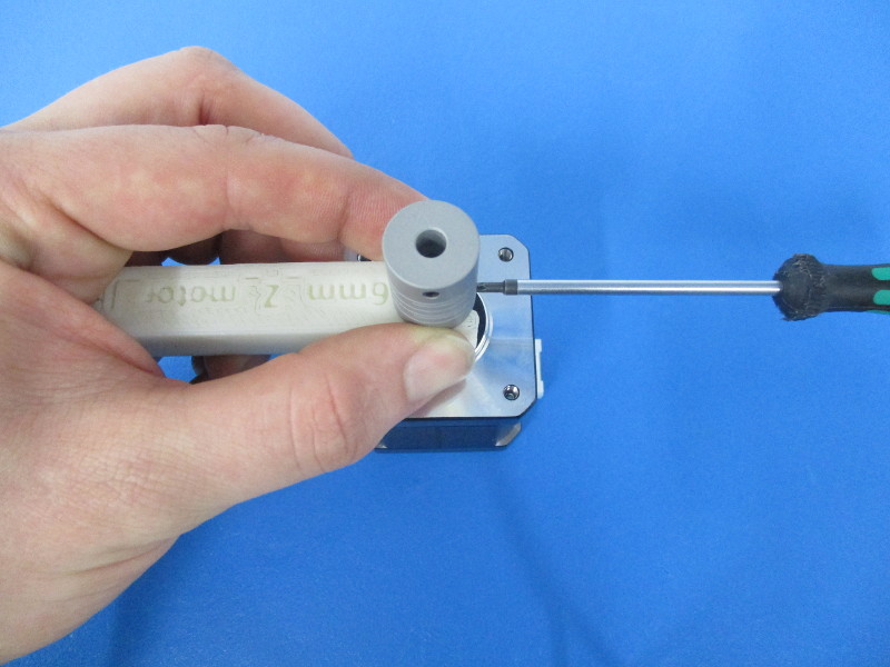
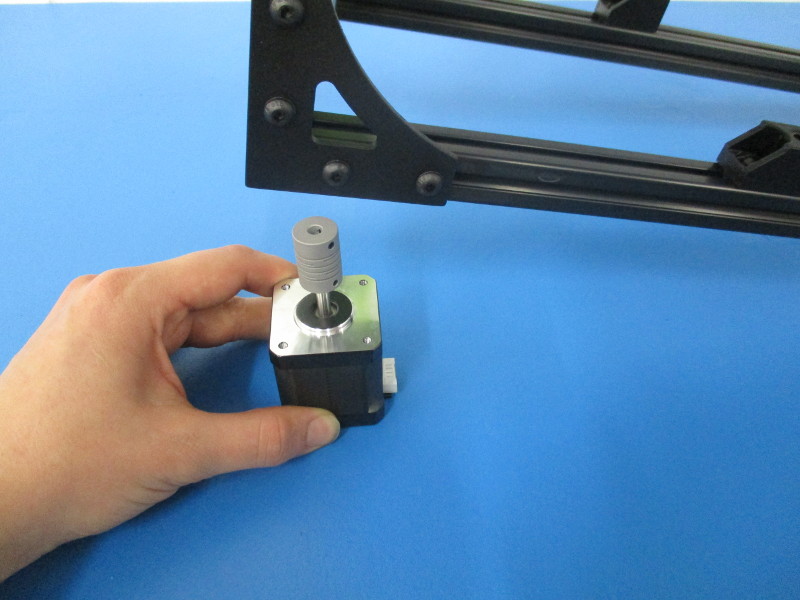
Attach couplers to both Z-Motors;
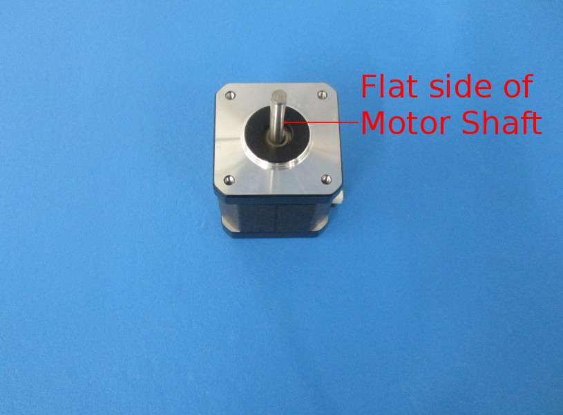
Locate the flat side of the motor shaft. To make alignment easier, rotate the flat side of the motor shaft towards your dominant hand.
Slide the coupler over the motor shaft.
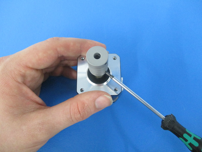
Space the distance between the coupler and the top surface of the motor with the printed 16mm Z Motor Jig.
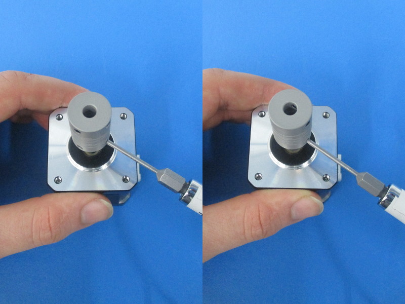
Using the 1.5mm Hex Driver, tighten one of the lower set crews of the coupler to the flat side of the motor shaft.
It is crucial that the first set screw to be tightened is aligned with the flat side of the motor shaft.
Tighten the other lower set screw, and torque both to 5in*lbs.
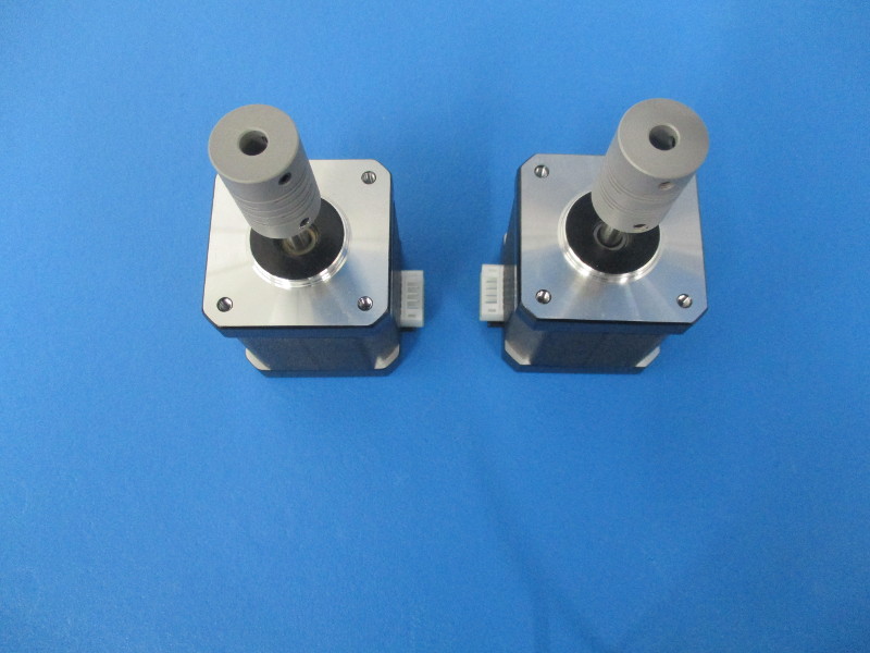
Gather parts:
2x Moons’ Motors with couplers attached – EL-MT0029 & HD-MS0351
4x M3x10 BHCS – HD-BT0148
4x M3 Black Washers – HD-WA0038
Required tools:
2mm Straight Tip Hex Driver
1.5mm Hex Driver
5in*lbs Torque Driver w/ 1.5mm Hex Bit installed
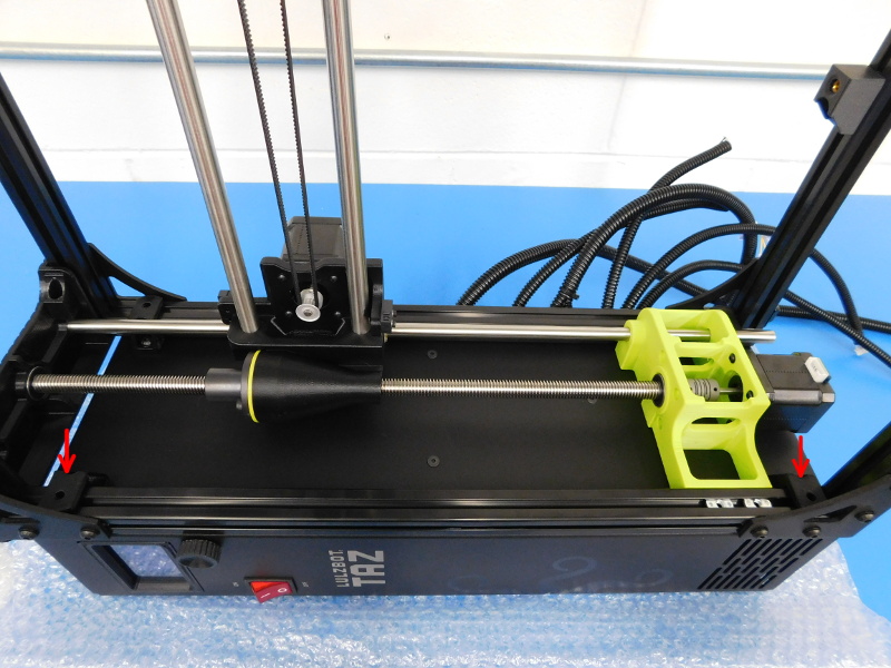
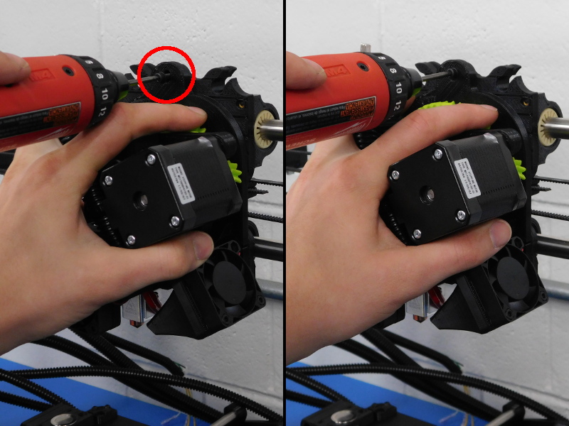
Attach motors to Z-Lower of frame;
Lifting that side of the frame off the workbench, slide one motor underneath with the connector facing inwards, as pictured.
Slide the coupler onto the lower end of the drive rod.
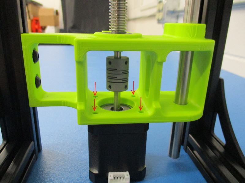
Place M3 Black Washers onto each M3x10 BHCS and begin threading, but do not tighten yet.
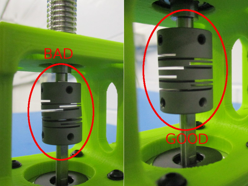
Alignment of the motor shaft to the drive rod is easiest determined by the straightness of the coupler.
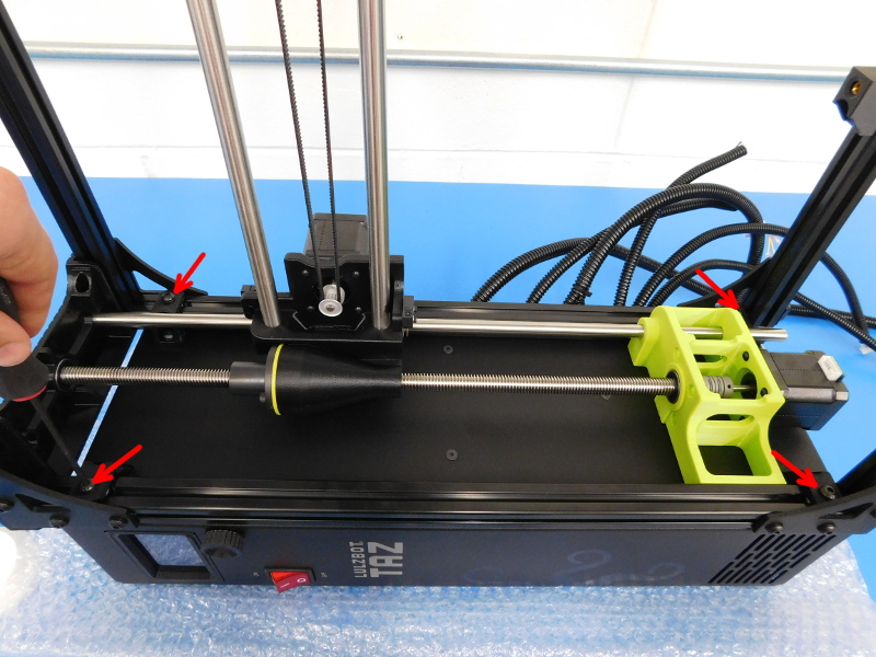
Position the motor on the Z-Lower so that the coupler remains straight and tighten all four M3x10 BHCS securing the motor to the motor mount once proper alignment has been achieved.
A good indicator is if the slots of the coupler remain the same size, larger or smaller gaps indicate an alignment issue.
Repeat for the other Z-Motor, ensuring that the connector for the motor is oriented inwards, towards the center of the frame, and that the coupler is straight once the motor has been tightened to the Z-Lower.
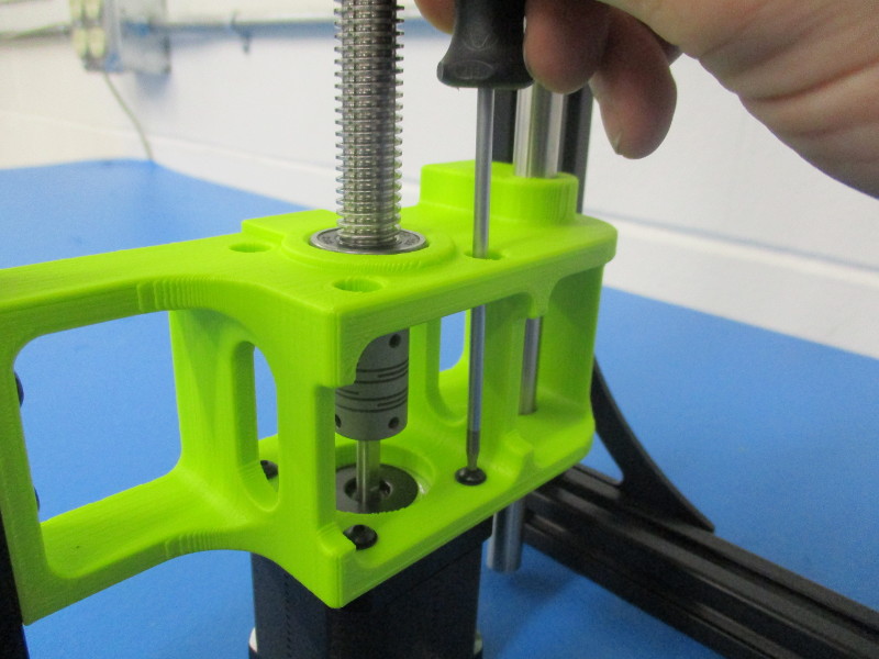
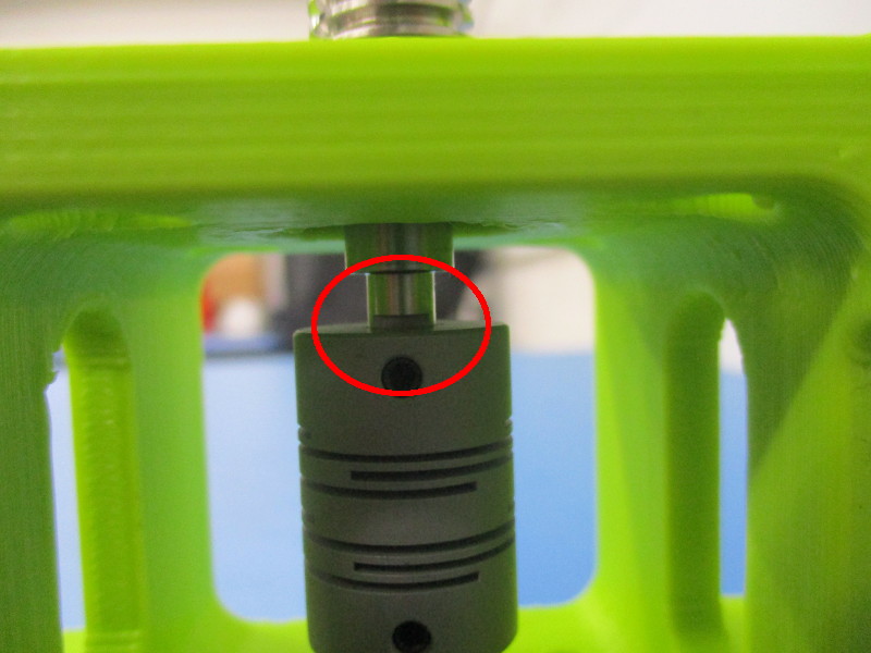
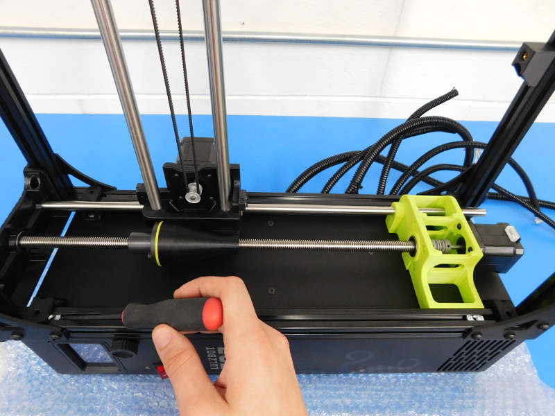
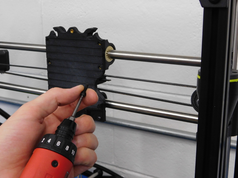
Tighten coupler’s set screws to drive rod end;
While rotating the drive rod by hand, observe near the top of the coupler to locate the flat side of the drive rod’s lower end.
Tighten one of the coupler’s upper set screws onto the flat side of the drive rod, before tightening the other. Torque both to 5in*lbs.
Repeat for the other side.

Gather parts:
4x Black Adhesive-Back Bumper, Square - HD-MS0336
Carefully lay the frame on its back.
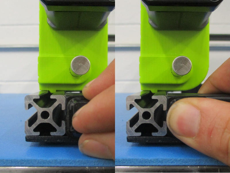
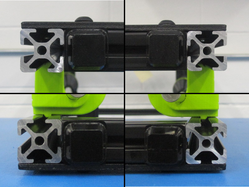
Apply one Rubber Bumper to each end of the lower horizontal extrusions of the frame.
Do not cover the open slots of the vertical extrusions, refer to image.
Ensure that the rubber feet are straight and don’t hang over the edge of the extrusion towards the inside of the frame as they can be ripped off by packaging materials.
Stand the frame up, but rotate so the back is facing you.
Gather Parts:
1x X-Carriage Assembly – AS-PR0032
2x 12mm X 515mm Stainless Steel Smooth Rod – HD-RD0047
4x M3x6 Set Screw – HD-BT0012
Required Tools:
Ruler
1.5mm Hex Driver
2in*lbs Torque Driver w/ 1.5mm Hex Bit installed
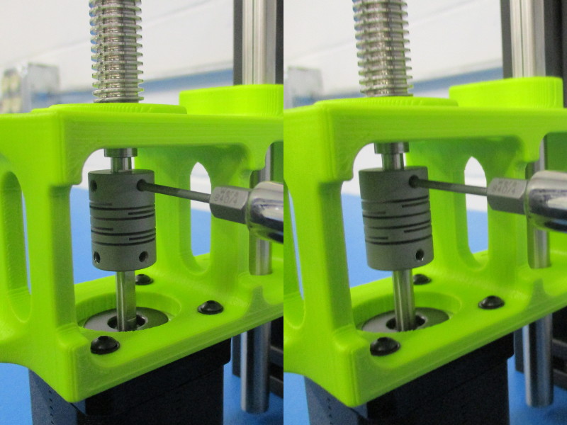
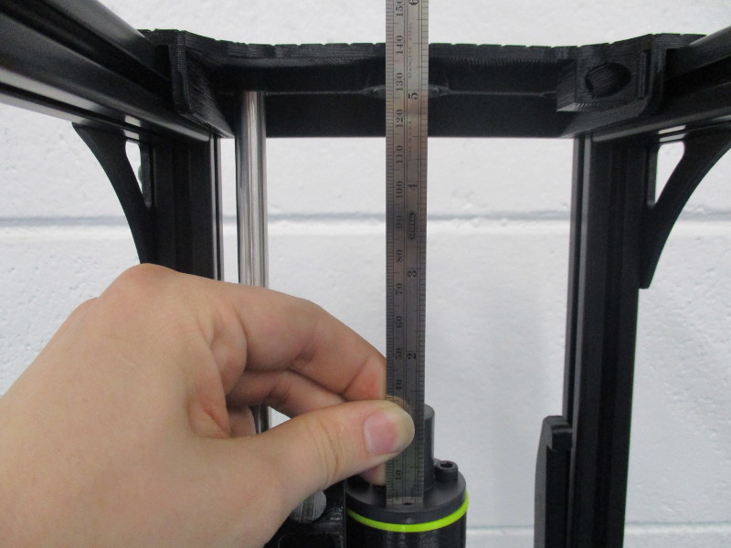
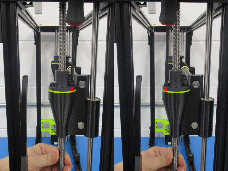
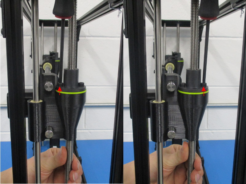
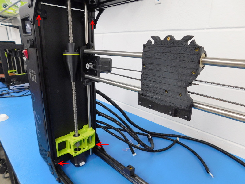
First we must ensure both ends of the X-Axis are at the same height.
To do so, you will measure with a ruler from the top of the Z-Nut to the top of the Z-Upper, as pictured.
Set both sides to the same height by rotating the drive rod by hand.
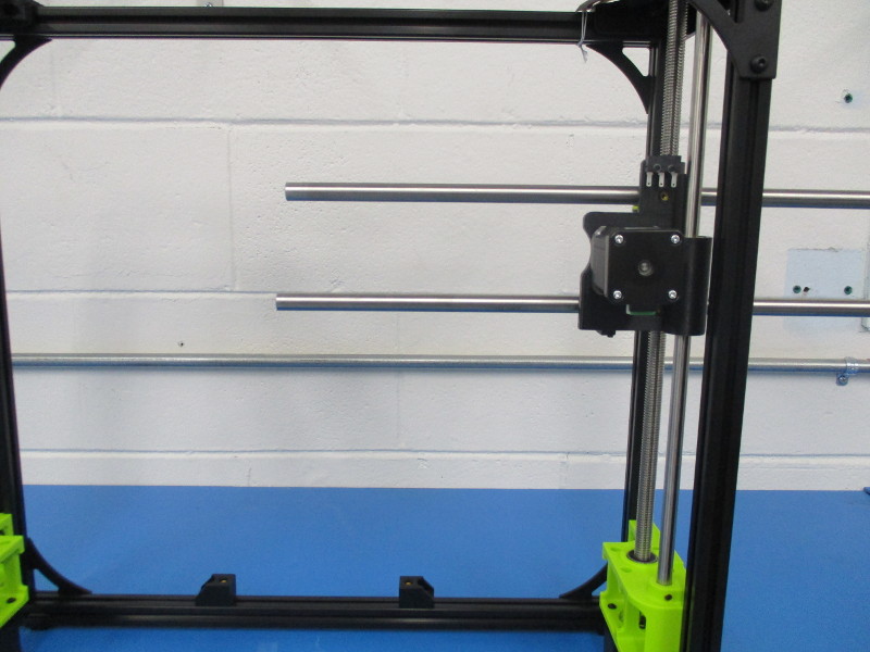
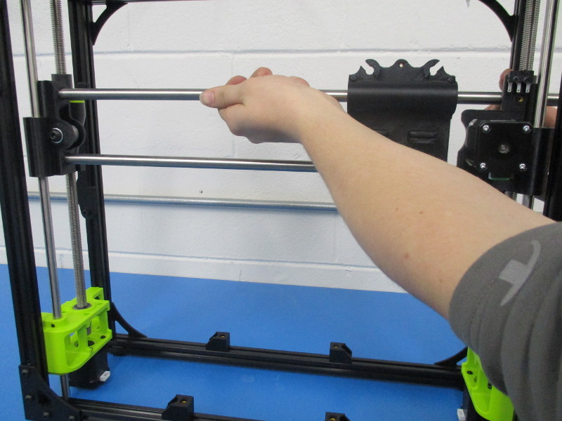
Begin inserting the 12mm Smooth Rods into the Z-Carriage Motor End, which should be to your right.
Slide them through about half way.
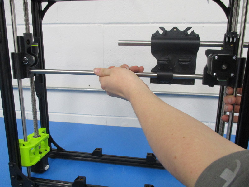
Slide the X-Carriage onto the Smooth Rods, with the bearings facing towards you, double bearing on top.
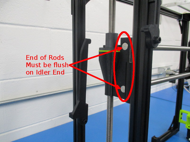
Slide the Smooth Rods the rest of the way, into the Z-Carriage Idler, until flush with the outside of the idler end.
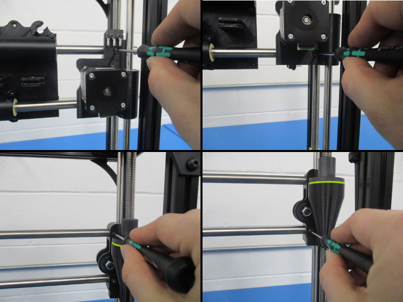
Insert two M3x6 Set Screws in each Z-Carriage.
On the Motor end they are located on the rear, on the Idler end they are located on the front.
Torque all Smooth Rod Set Screws to 2in*lbs

At this point we want to take a few steps to ensure the Z-Axis will operate smoothly. This action will be performed on both sides before proceeding.
Using your hand, attempt to rotate the drive rod in both directions.
Does it rotate easily?
Are both screws securing the Z-Nut to the Z-Carriage tight, but not over-tight?
If answered no to either question, loosen both M5 screws securing the Z-Nut using a 4mm Ball Tip Hex Driver.
While rotating the drive rod by hand, gradually tighten the rear Z-Nut Mounting screw until the drive rod begins to get harder to turn.
Now gradually tighten the front one while rotating the drive rod by hand until you reach the “sweet spot” where the drive rod becomes easy to rotate by hand.
Perform the same adjustment to the other side, and you should be good to go!
Gather Parts:
1x GT 2 Single Sided Neoprene Belt - 1164mm by 6mm – HD-BL0032
2x M3x12 SHCS – HD-BT0039
2x M3 Black Washers – HD-WA0038
Required Tools:
Cordless Electric Driver w/ 2mm Hex Bit installed, torque setting ~3
2.5mm Ball Tip Hex Driver
Pliers
Cutters
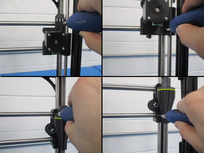
Using the cordless driver, tighten both bearing holders to the X-Carriage.
After tightening, verify that the X-Carriage slides smoothly from end to end.
Cut a Belt (HD-BL0032) at an angle, this will help it feed through the Idler end easier.
Apply M3 Black Washers to both M3x12 SHCS (HD-BT0039 & HD-WA0038)
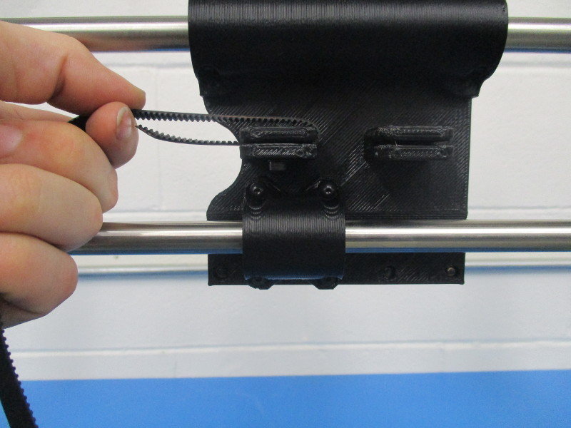
Place the end of a belt in the left clamp of the X-Carriage, teeth facing up, with the end of the belt facing left.
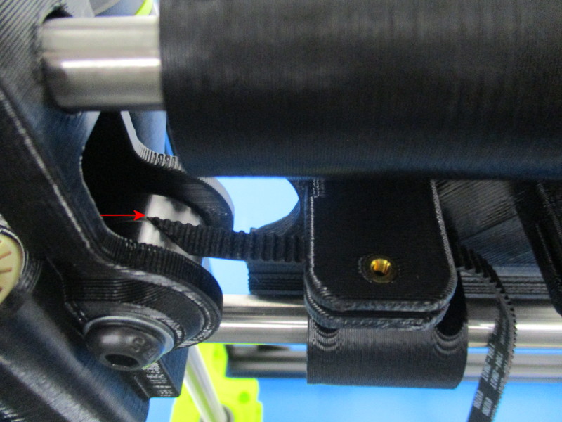
The belt position in the left clamp impacts how the belt rides in the Idler bearings during axis motion;
If the belt is placed too far into the clamp it can cause the belt to ride towards the front of the Idler and rub on the plastic. A belt in this position will often rub against the single bearing holder as well and may cause the belt to slip under tension due to not enough grip on the belt.
If the belt is not in the clamp far enough it tends to ride towards the rear of the Idler bearings and rub against the plastic.
The belt should not rub against plastic at any point of axis motion.
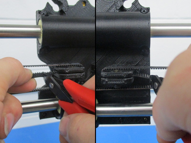
A good way to check this alignment before tightening the belt is to slide the X-Carriage towards the idler. The front edge of the belt (currently farthest from you) should line up roughly with the center line between the two bearings of the Idler. See picture for reference.
Secure the belt in the left clamp with one M3x12 SHCS (with washer).
DO NOT over-tighten! The belt clamps on the X-Carriage break easily when over-tightened. Do not attempt to make the tongues of the belt clamp touch, a small gap should remain.
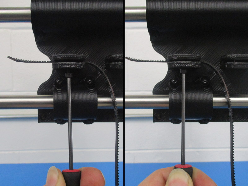
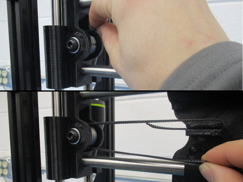
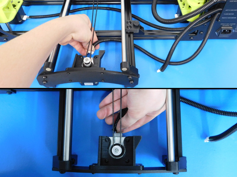
Flip the belt over the clamp counter-clockwise, and feed the end of the belt through the Idler, starting from the top with the teeth facing down.
Pull the remaining length through the Idler and loop around the X-Motor pulley.
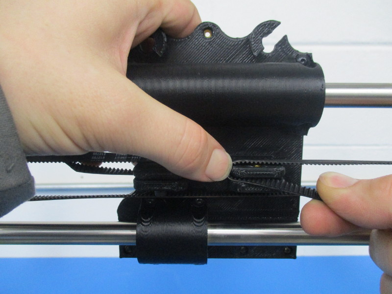
Place the belt over the right clamp on the X-Carriage and bend counter-clockwise to enter the clamp.
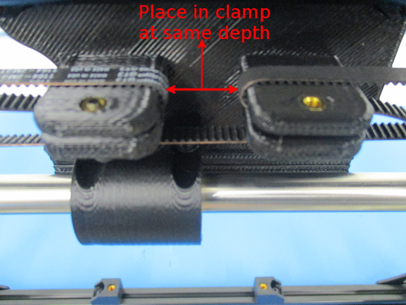
Line up the belt’s position in this side of the clamp with the belt’s position in the left clamp.
Install one M3x12 SHCS (with washer) but do not tighten.
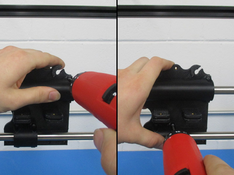
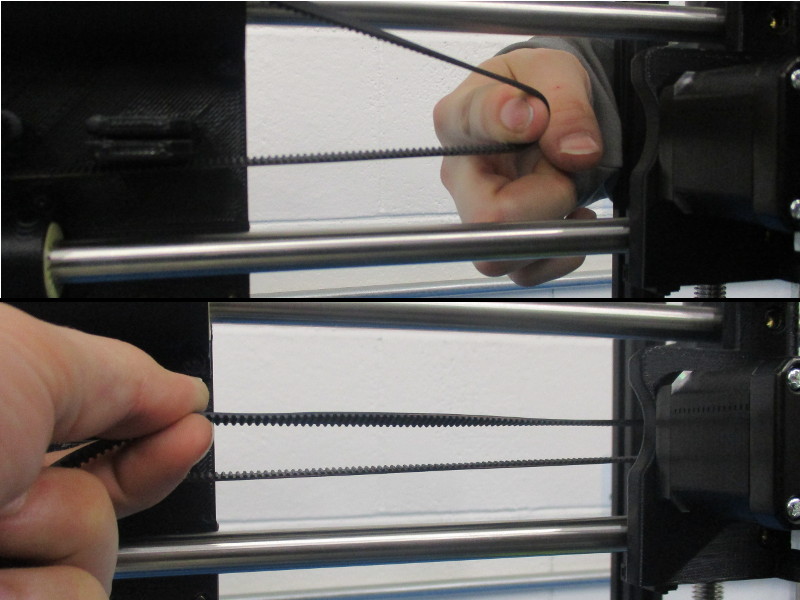
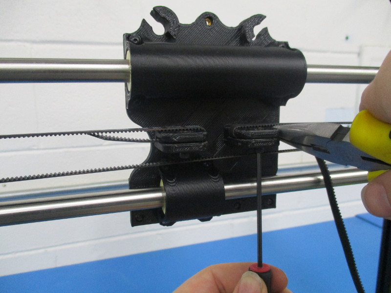
Grip the excess length of the belt protruding from the right clamp with the pliers, as close to the clamp as possible.
While holding grip with the pliers, rotate to apply tension to the belt.
Tighten the M3x12 SHCS installed previously to secure the belt with tension applied.
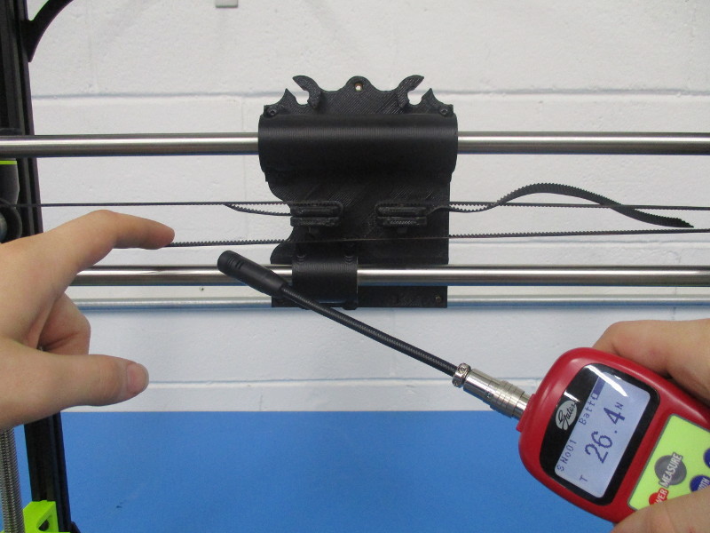
Use the Gates Sonic Tension Meter to dial in belt tension to 23-27 Newtons, several adjustment attempts may be necessary before proper tension is achieved.
Once tension on the belt is properly set, cut off the excess belt from both sides of the clamp but leave about 10mm protruding. This allows for grip should the belt tension need adjusted post-assembly.
By hand, move the axis from end to end and make sure movement is still smooth throughout. Also watch the belt's position on the Idler bearings as you move the axis to ensure that no friction contact occurs with any plastic parts.


Gather Parts:
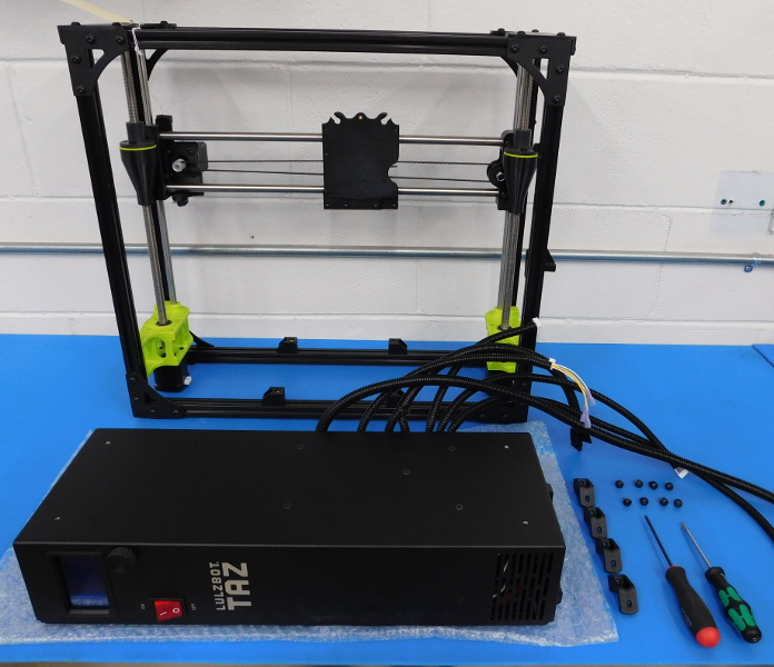
1x TAZ6 Control Box Assembly, Tested – AS-PR0004
4x Electronic Case Mount – PP-GP0154
8x M5x10 BHCS – HD-BT0073
8x M5 Black Washer – HD-WA0040
4x M5 T-Nut – HD-NT0053
Required Tools:
3mm Ball Tip Hex Driver
3mm Straight Tip Hex Driver
Rotate the frame so the front is facing you, and set it towards the rear of your workbench.
Make sure your workspace is free of debris or loose hardware before laying down a painted assembly.
Obtain a completed TAZ6 Control Box (AS-PR0004) and inspect for any cosmetic defects.
Carefully lay the Control Box on its left side with the front facing you.
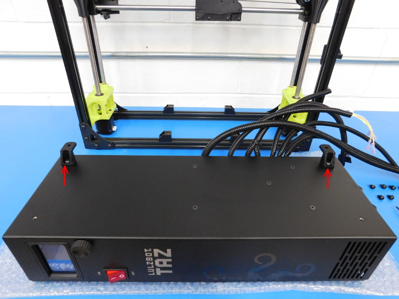
Attach two Electronics Case Mounts (PP-GP0154) to the 2 rear-most mounting positions, as pictured, using two M5x10 BHCS (HD-BT0073 with washer HD-WA0040). The case mounts should face perpendicular to the length of the Control Box.
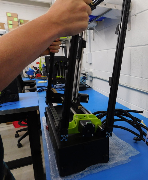
Lift the frame grasping the top and bottom front extrusions so that the left side of the frame is facing down.
Rotate the right side (currently facing up) away from you.
Carefully line up the frame with the case mounts attached to the control box.
While rotating top towards you, slide the frame forward and into position on the Control Box.
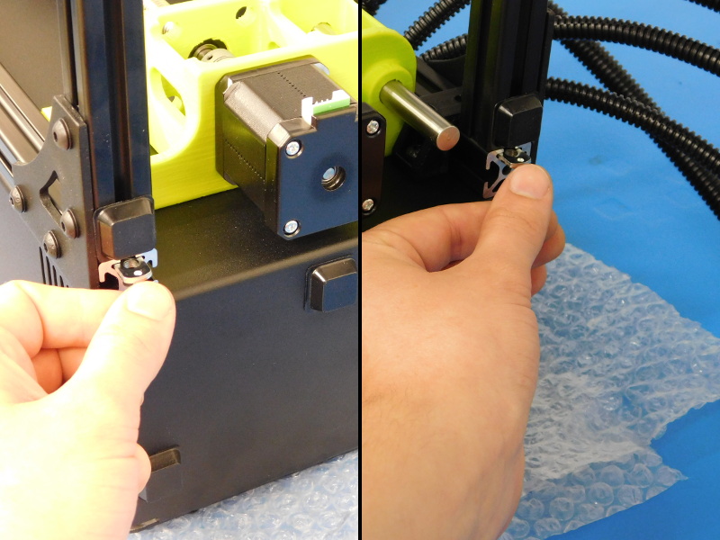
Slide two M5 T-Nuts (HD-NT0053) into the upward facing slots on each side of the frame against the Control Box, see picture.
Attach the remaining two Electronics Case Mounts (PP-GP0154) to the front two mounting provisions on the Control Box using two M5x10 BHCS (HD-BT0073 with washer HD-WA0040).
Using a screwdriver or suitable tool, line up the T-Nuts with the Electronics Case Mounts.
Attach all four Electronics Case Mounts to the frame with four M5x10 BHCS (HD-BT0073 with washer HD-WA0040)
Leave these screws loose for now so that the Control Box can be leveled with the table.
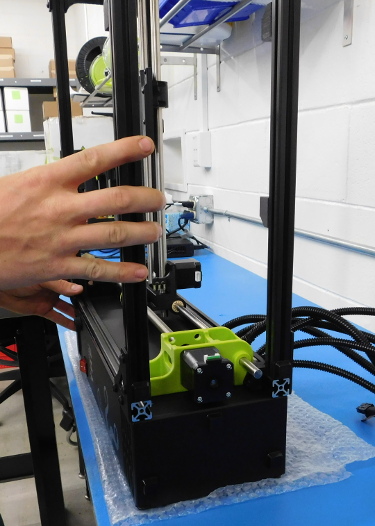
Carefully lift the machine and stand it up on the rubber feet, visually verify that all four rubber feet of the frame sit flat on the workbench and are not lifted by the Control Box.
Tighten all 8 screws mounting the Control Box to the frame, be careful not to over-tighten as the case mounts can split.

Gather Parts:
1x TAZ6 Y-Axis Assembly – AS-PR0021
Required Tools:
3mm Ball Tip Hex Driver
Bed Spacer from Control Box 135mm – Printed Jig
Before mounting the Y-Axis perform the following quality checks:
Are all M5 frame screws on the Y-axis tightened?
Are all M3 screws securing the Bearing holders to the Bed Plate tightened?
By hand, move the axis from end to end, is it smooth without binding?
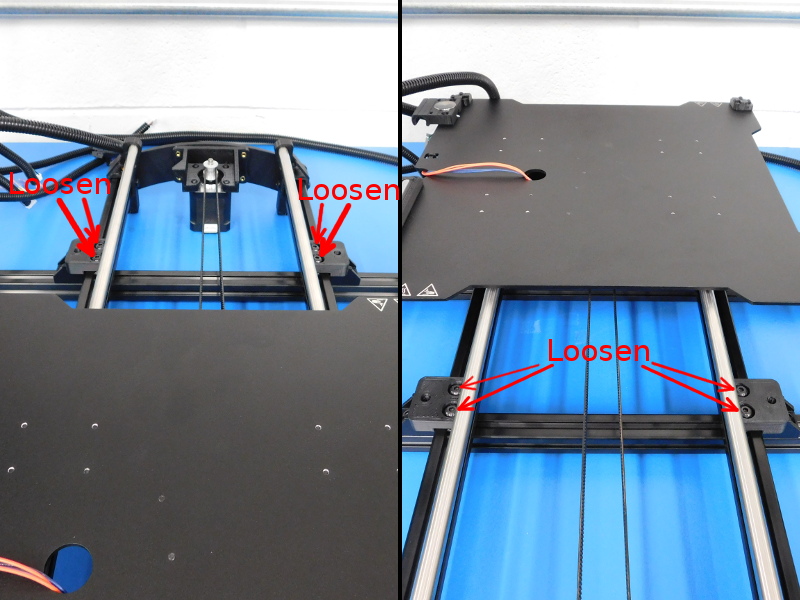
Using the Bed Spacer from Control Box 135mm (printed jig), space the both left Y-Chassis Mounts 135mm from the inside of the left extrusion.
Loosen both right Y-Chassis mounts and slide them to your right.

Gather Parts:
1x TAZ6 Y-Axis Assembly – AS-PR0021
Required Tools:
3mm Ball Tip Hex Driver
Y-Frame offset fixture A – 110mm
Orange Y-Axis Frame Square
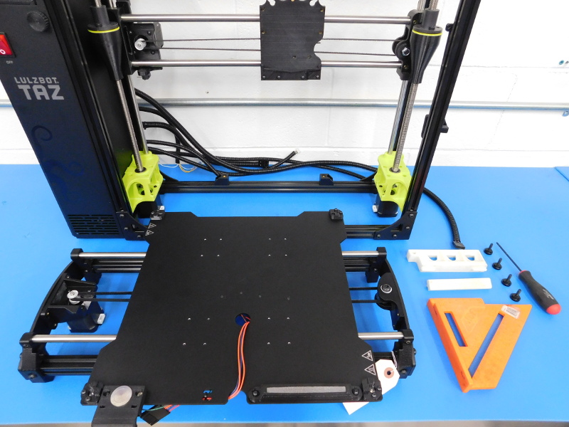
Place the Y-Axis over the frame with the motor end to the back.
Loose both screws on all four Y-Table Mounts.
Place Y Table Mounts over Y-Chassis Mounts and secure with M5 Thumb Screws (HD-MS0055)
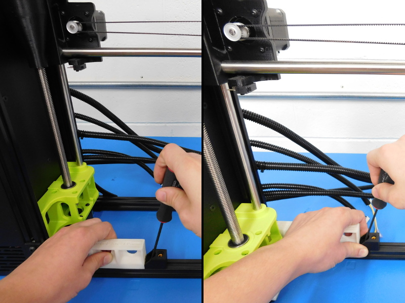
Place Y-Frame offset fixture A (110mm) onto the rear of the left Y-Frame extrusion, as pictured.
Pull the Y-Axis forward so that the printed fixture doesn’t wiggle back and forth, and tighten the two screws in the Y-Table mount closest to it.
Using the orange Y-Axis frame square in the position pictured, position the Y-Axis so that it is square with the frame and tighten all remaining mounting screws, including the two right Y-Chassis Mounts.


Gather Parts:
1x TAZ6 Extruder Assembly – AS-TH0014
1x M3x12 SHCS – HD-BT0039
1x M3 Black Washer – HD-WA0038
Required Tools:
Red Milwaukee Power Driver w/ 2.5mm Hex Bit installed
Before Mounting the extruder, perform the following quality checks:
Are the extruder gears aligned properly without backlash?
Is the front of the heater block parallel with the mount plate?
If uncertain about any quality concerns with the extruder assembly, refer to your supervisor or Manufacturing Engineering Technician.
Place the M3x12 SHCS (HD-BT0039 with washer HD-WA0038) on the 2.5mm Hex Bit installed on the power driver in your dominant hand, with your other hand, grasp the extruder.
Place the extruder mount into the guide on the X-Carriage and apply some pressure downwards to make sure it seats fully.
Secure with the M3x12 SHCS.
The extruder should be tight in the mount and not wiggle side to side.
Gather Parts:
7x Wire Tie, 8” Black – HD-MS0058
Required Tools:
Flush Cutters and/or Zip Tie Gun
Extruder Cable Zip Tie Spacer
Carefully lift the machine and rotate so the back is facing you.
Beginning with the Extruder Cable and working your way down, route and secure all cabling as follows:
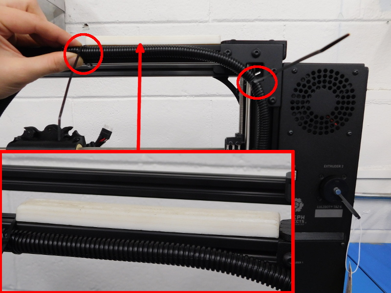
Extruder Cable:
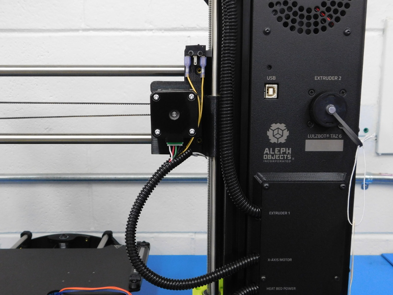
Route the Extruder Cable up along the frame to the frame corner, secure as pictured.
Using the Extruder Cable Zip Tie Spacer, place as pictured and secure the cable to the frame at its end.
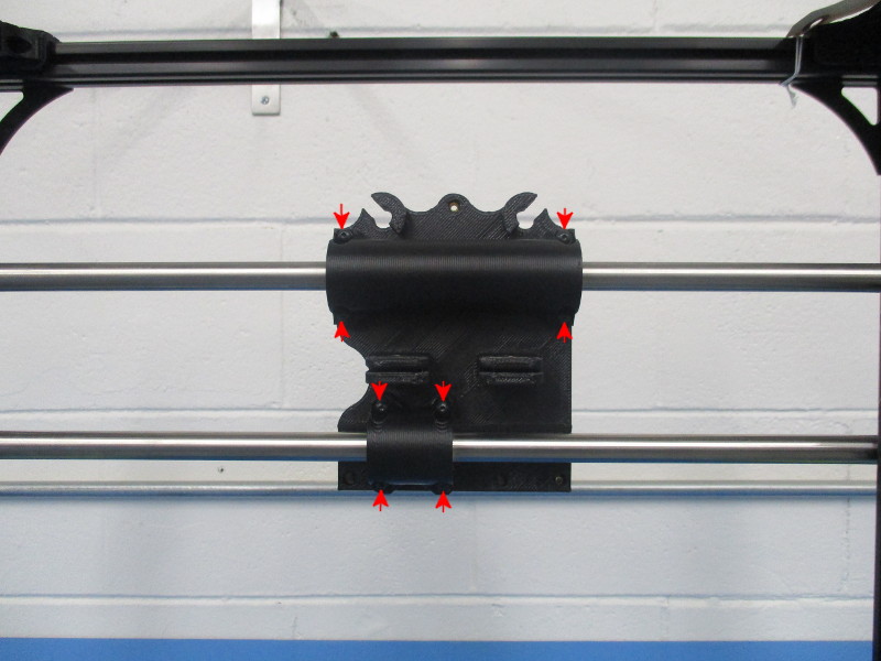
Place the end of the extruder cable (leaving ~10mm towards the front) into the right-most slot on the top of the X-Carriage.
Secure with a Zip Tie as pictured.
Line up the arrow stickers and carefully plug in the extruder.
X-Axis Motor:
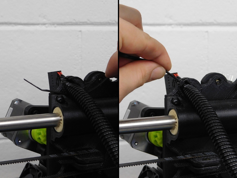
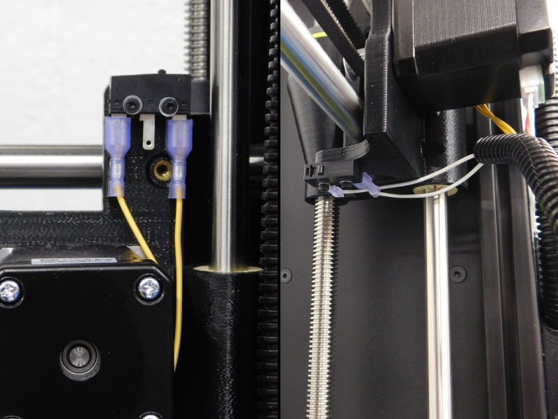
The two yellow wires will plug into the Z-Max end stop switch as pictured. Note the middle post is open on all TAZ 6 end stop switches.
The two white wires will plug into the X-Min Switch, as pictured.
Plug the motor connector into the motor and tidy up the panduit, the panduit should follow yellow/white with the end of the motor wire exiting the side, as pictured.
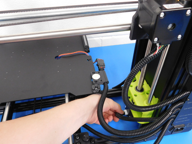
Heat Bed:
Plug the 8-pin connector into the 8-pin connector on the Y-Axis.
Insert the cable into the cable pathway of the Z-Min Switch mount, as pictured.
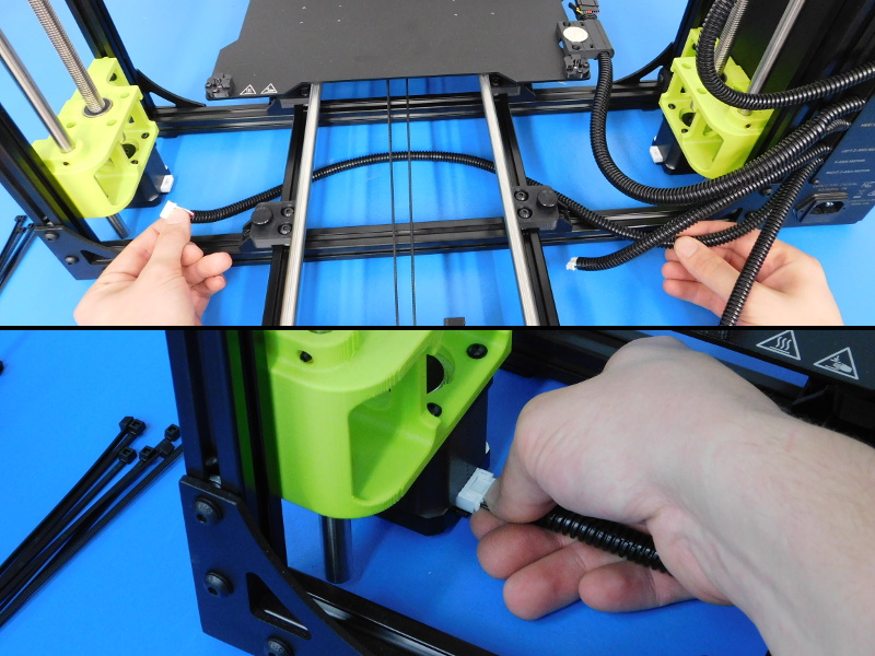
Z & Y Motor Extensions:
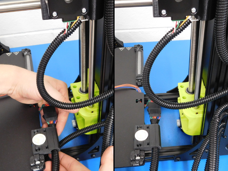
Locate the Right Z-Axis Motor Extension, which will be the longest of the 3 remaining. This cable will route across the inside of the frame underneath the Y-Axis to plug into the Z-Right Motor.
Locate the Y-Axis Motor Extension and plug it into the Y-Axis Motor.
Plug the Z-Left Motor Extension into the left Z-Motor.
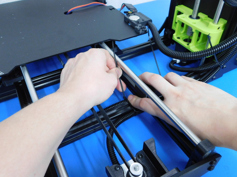
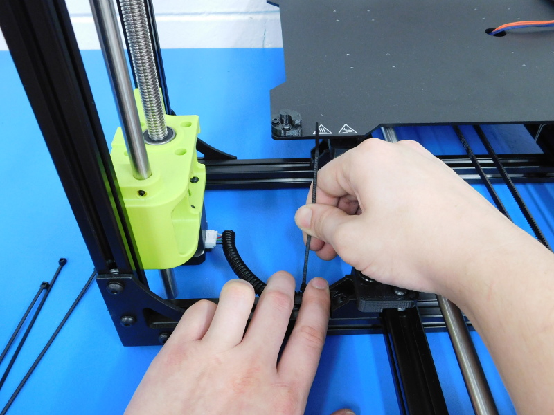
Secure all 3 of these cables neatly to the frame corner, as pictured. The wires should not be bunched up, twisted, or otherwise unnecessarily crossed.
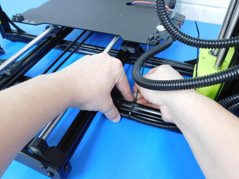
Secure the Right Z-Axis Motor Extension and Y-Axis Motor Extension to the sides of the lower extrusion, as pictured. The zip tie should be a finger’s width from the Y-chassis Mount, as pictured.
Place another Zip Tie securing the two cables a finger’s width from the inside of the left Y-Axis frame extrusion, as pictured.
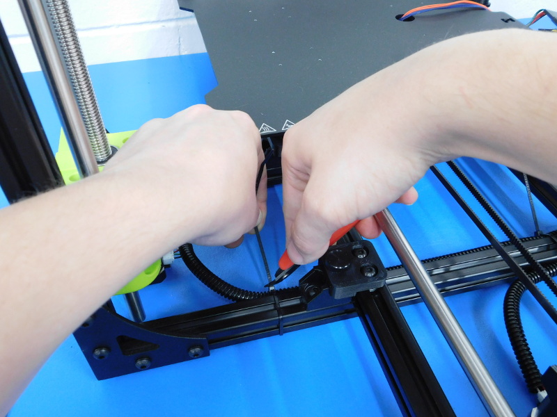
The last wire tie will be placed a finger’s width from the right rear Y-Chassis Mount, securing the Right Z-Motor Extension to the frame.
When finished, cut all zip tie ends as flush as possible with a pair of clippers, or a zip-tie gun.


Carefully lift the machine and rotate so the front is facing you.
On the rear of the Control Box;
Connect the power cable to the receptacle
Connect the printer to your workstation computer via USB
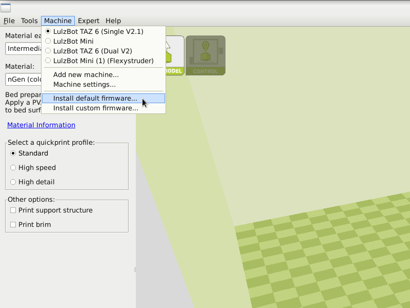
In Cura, open “Machine” in the top menu bar and make sure "TAZ 6 Single V2.1" is selected, then select “Install default firmware...”
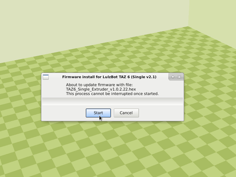
In the dialogue that appears, select “Start”
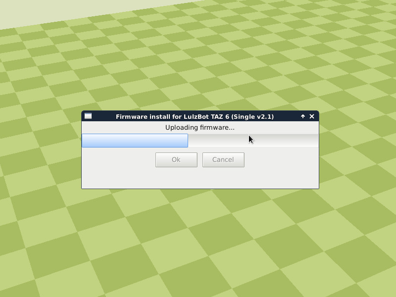
Once flashing of the firmware is complete, the printer will reboot.
Insert an SD card flashed for final assembly, which will include the gcodes used for testing at completion of final assembly.
The SD card is inserted in the slot on the left side of the control box with the shiny contacts of the SD card facing towards you.
Click the printers control knob, scroll down to “Print from SD” and click again.
Select “XYZ_tester.gcode” from the list
Observe while the machine runs to ensure that all axis operate properly especially during motion of the Z-Axis. Ensure the Z-Axis is free of excess noise, vibration, or binding throughout the entirety of its motion.
Tag the Machine with your name, and place it onto the racks to be taken by the calibration team.