Open HardwareAssembly Instructions
Guides for installation and assembly of the LulzBot line of products made by FAME 3D LLC.
Guides for installation and assembly of the LulzBot line of products made by FAME 3D LLC.
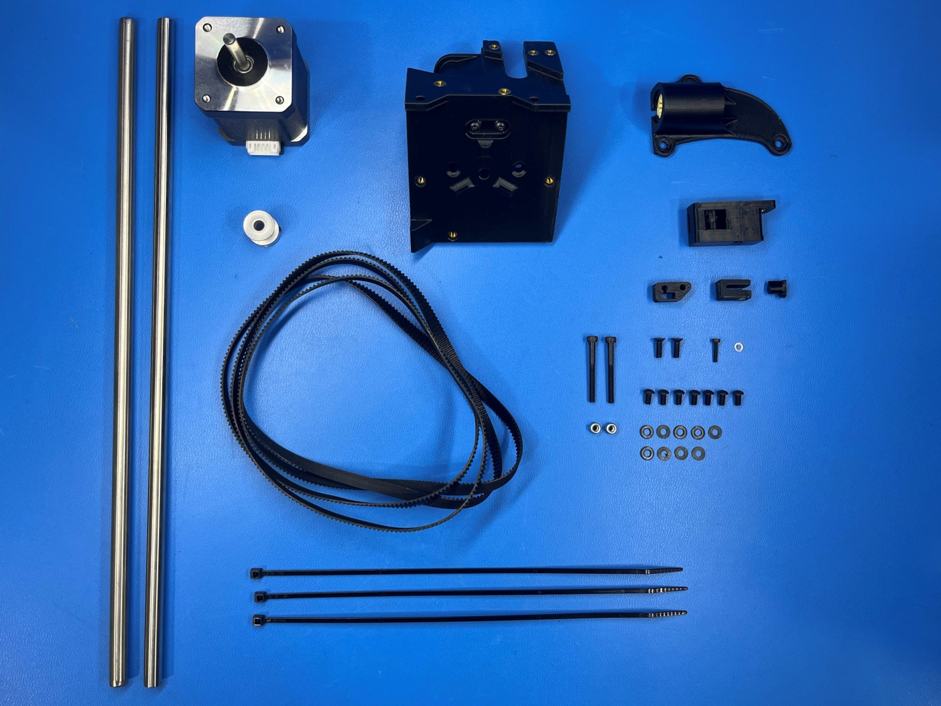
1x- [EL-MT0068] NEMA 17 Stepper Motor
2x- [HD-BT0042] M3x30 SHCS, Black-Oxide
1x- [HD-BT0107] M2x10 SHCS, Black-Oxide
2x- [HD-BT0116] M3x10 FHCS, Black-Oxide
7x- [HD-BT0140] M3x6 BHCS, Black-Oxide
2x- [HD-BL0033] Single Sided Neoprene Belt, 744mm
1x- [HD-MS0033] 16 Teeth, Timing Pulley
3x- [HD-MS0058] Wire Tie 8"
2x- [HD-NT0001] M3 Locknut
2x- [HD-RD0035] Smooth Rod 315mm
1x- [HD-WA0012] M2 Washer, Zinc
9x- [HD-WA0038] M3 Washer
1x- [PP-GP0132] X Carriage
1x- [PP-GP0135] X Axis Single Bearing Holder
1x- [PP-GP0484] Adjustable X Axis Belt Mount
1x- [PP-GP0493] Belt Tension Split Collar
1x- [PP-GP0494] Belt Tension Split Teardrop
1x- [PP-GP0680] U Channel Belt Clamp
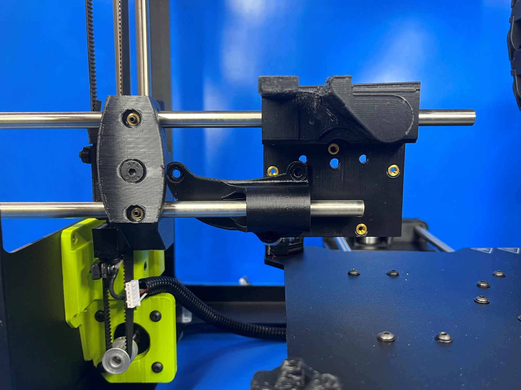
Slide 1x smooth rod [HD-RD0035] into the top hole on the X end idler. Once the rod is about half way through slide the X carriage [PP-GP0132] onto the rod making sure the flat slide faces the front of the printer and that it points down.
Take another smooth rod and slide half way through the bottom hole on the X end idler, and then slide the X axis single bearing holder [PP-GP0135] making sure the three holes align with the three brass inserts on the X carriage.
Once the X carriage and X axis single bearing holder are on the rods, slide both smooth rods into the two holes on the X end motor. Make sure the rods are fully seated inside the two holes.
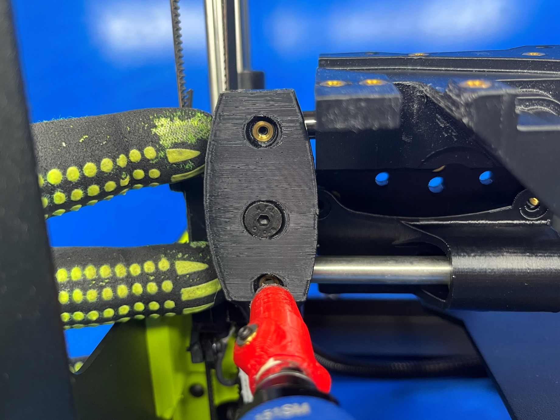
Then torque the two set screws on the side of the X end idler to 3 in*lbs.
Note: If the X end idler is missing a set screw use [HD-BT0012] to replace it.

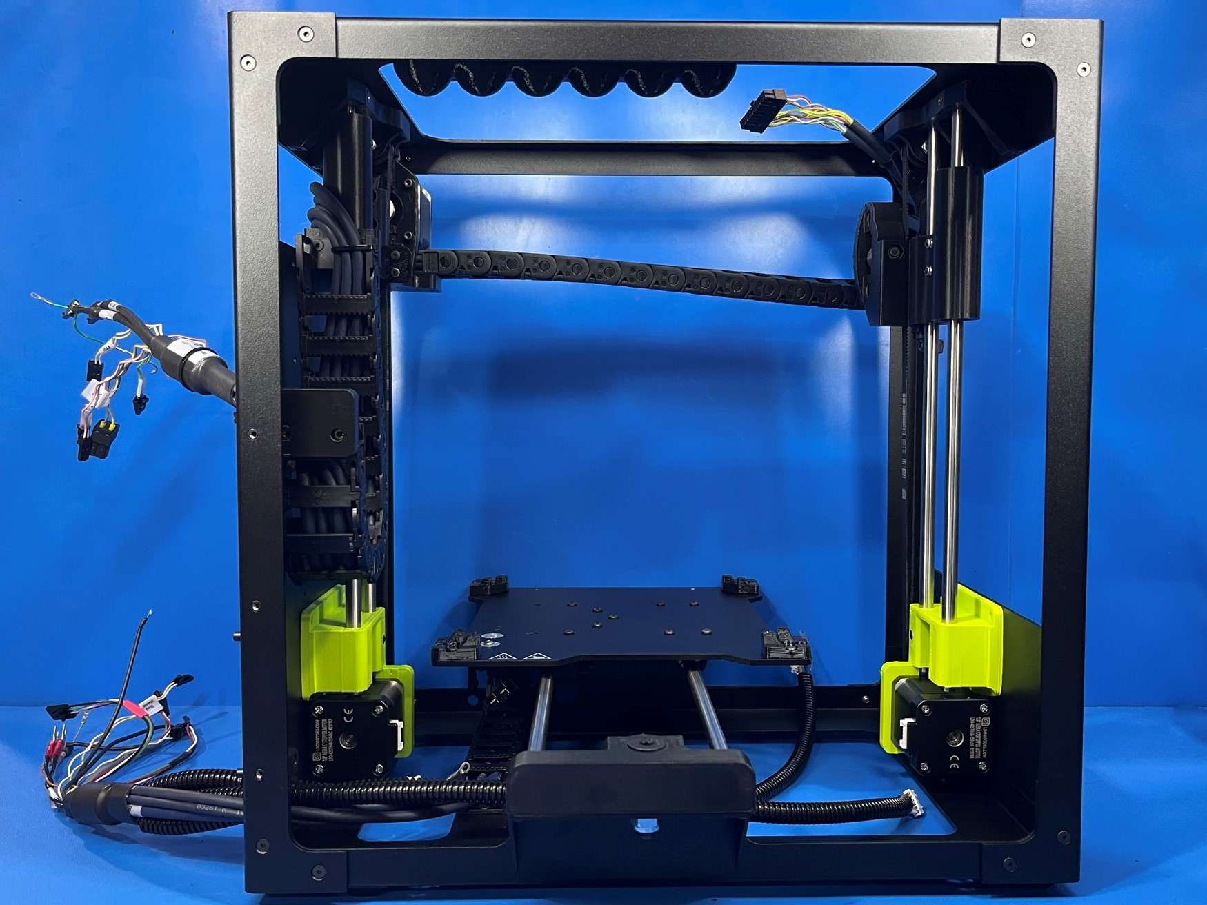
Flip the frame assembly so the bottom frame is facing up and so the Y-Axis motor is closest to you. Route the second longest wire, that has a motor connector, through the hole next to the motor. Plug in the wire.
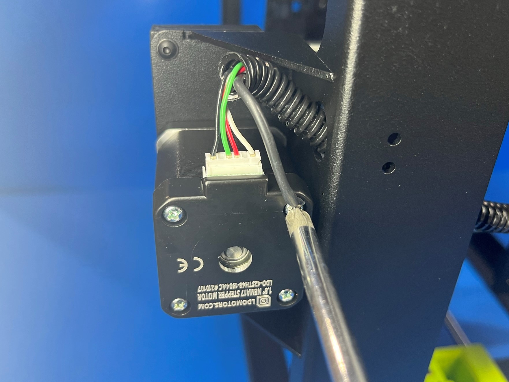
Then remove back left screw from the Y-Axis motor and place the ring from the ground wire over the screw and then fasten the screw and ground wire into the motor. [reference#2] Make sure the ground wire is angled towards the motor connection wires
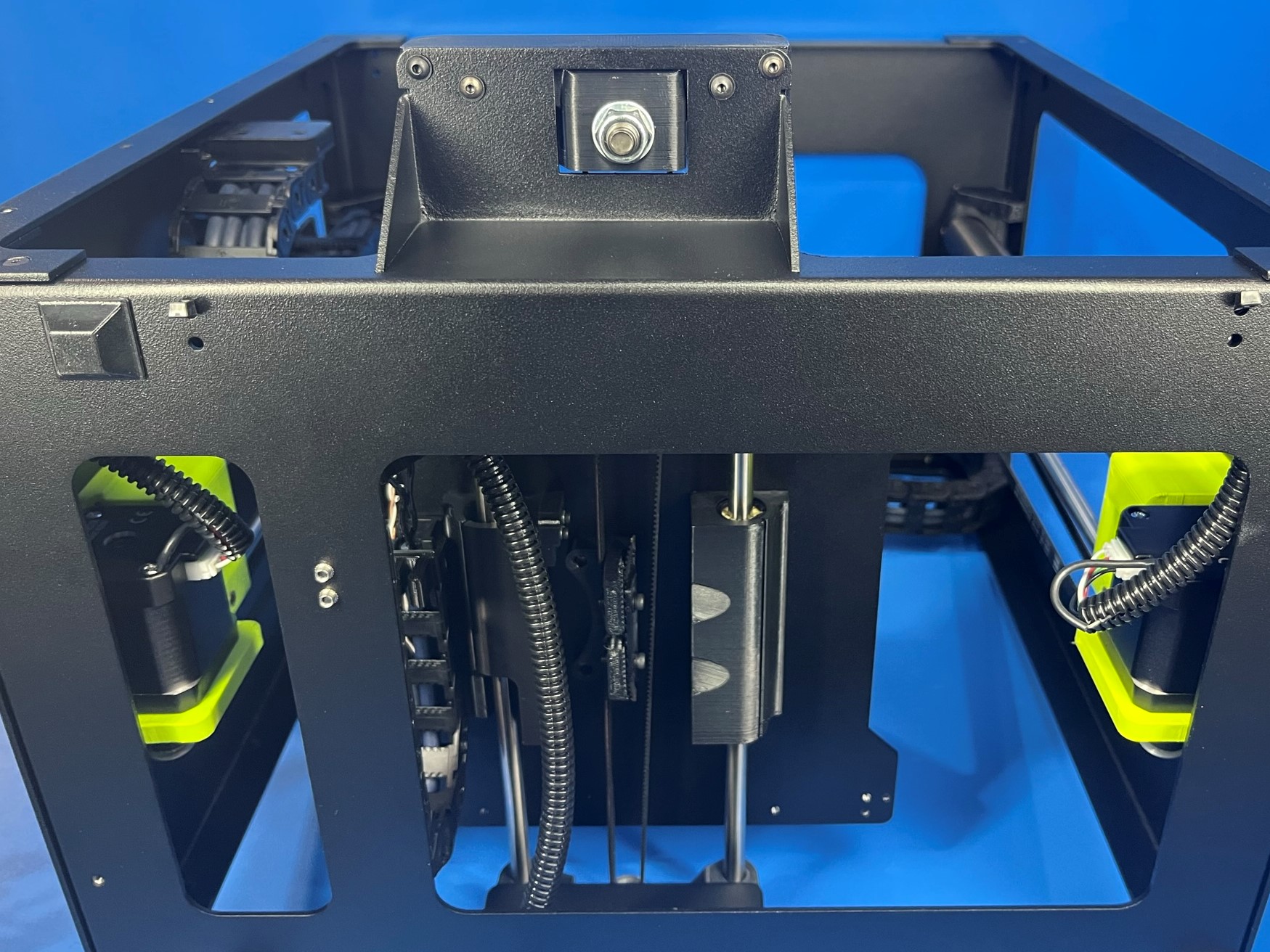
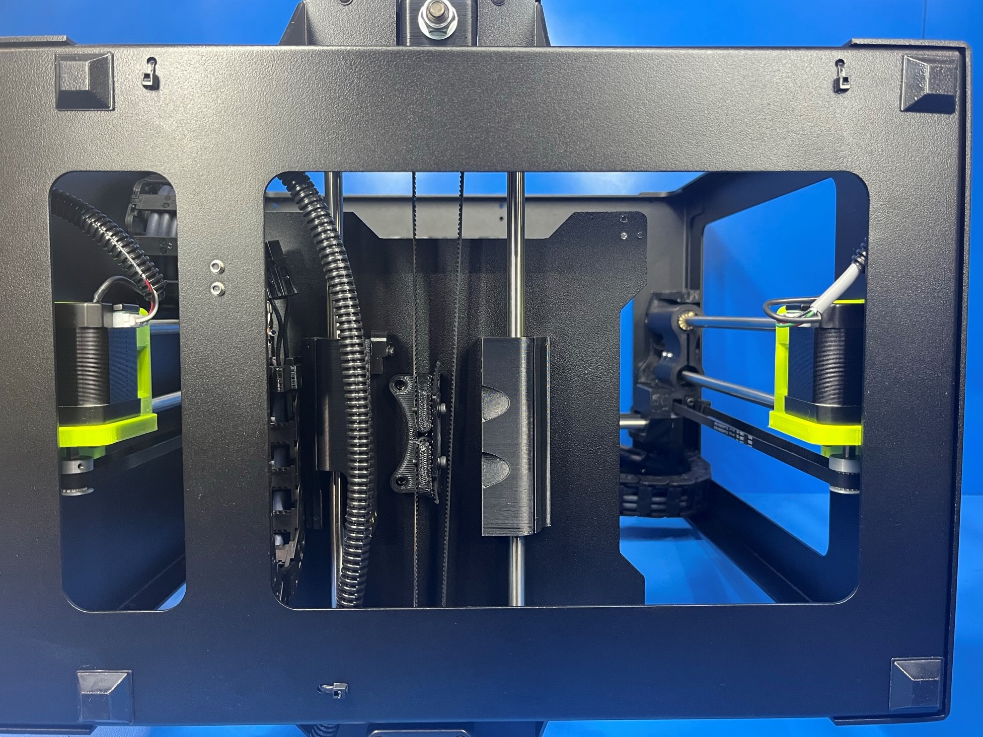
Repeat for the Z-Axis motors Flip Frame Assembly so the front of the printer is facing you and the top frame plate is facing up. Route the shortest wire to the Z-Axis left motor, and the longest wire to the Z-Axis right motor. Plug in both wires.
Remove the bottom right screw on the Z-Axis left motor and place the ring from the ground wire over the screw and then fasten the screw and ground wire into the motor. [reference#3] Make sure the ground wire is angled towards the motor connection wires
Remove the bottom left screw on the Z-Axis right motor and place the ring from the ground wire over the screw and then fasten the screw and ground wire into the motor. [reference#4] Make sure the ground wire is angled towards the motor connection wires
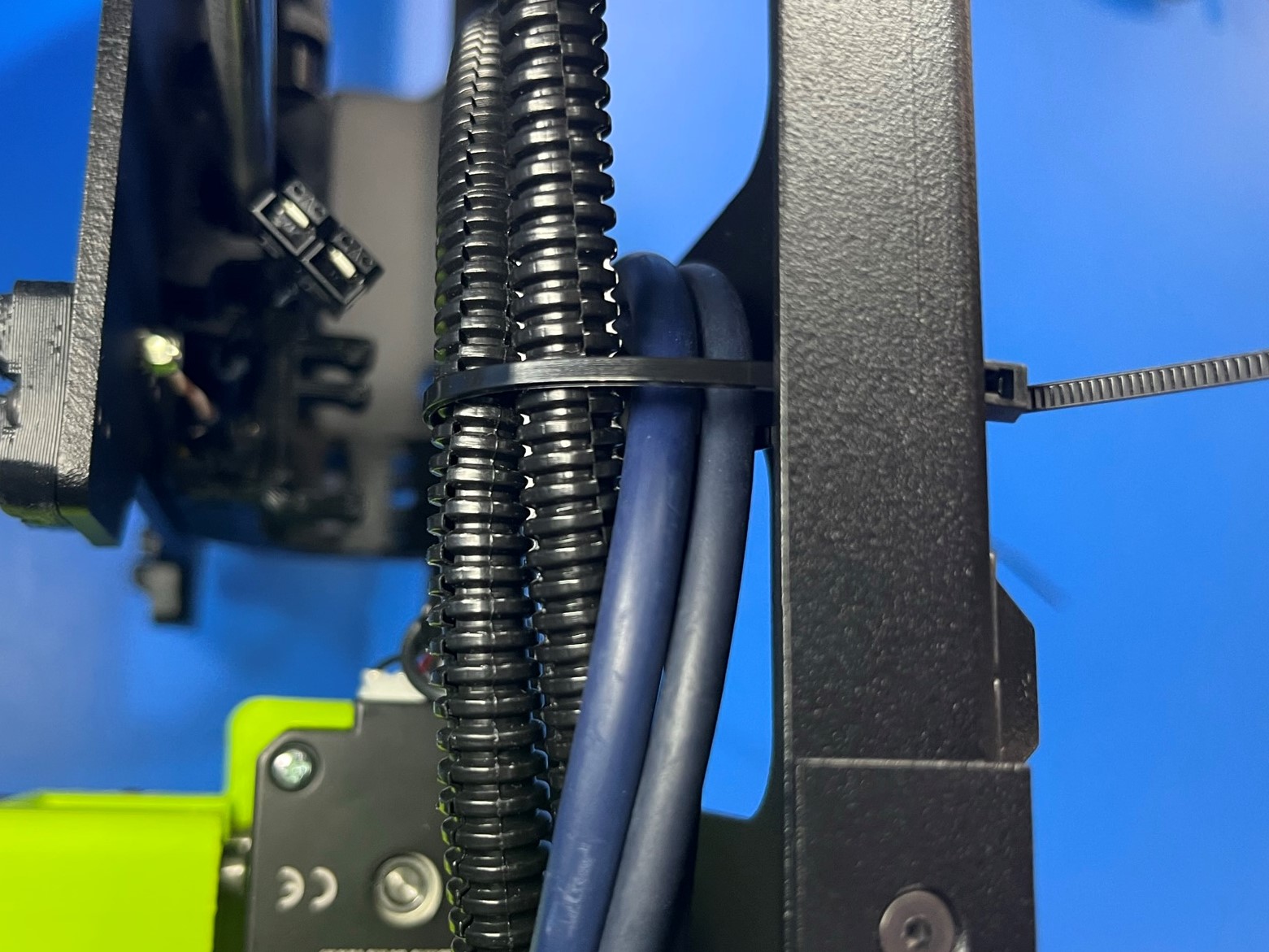
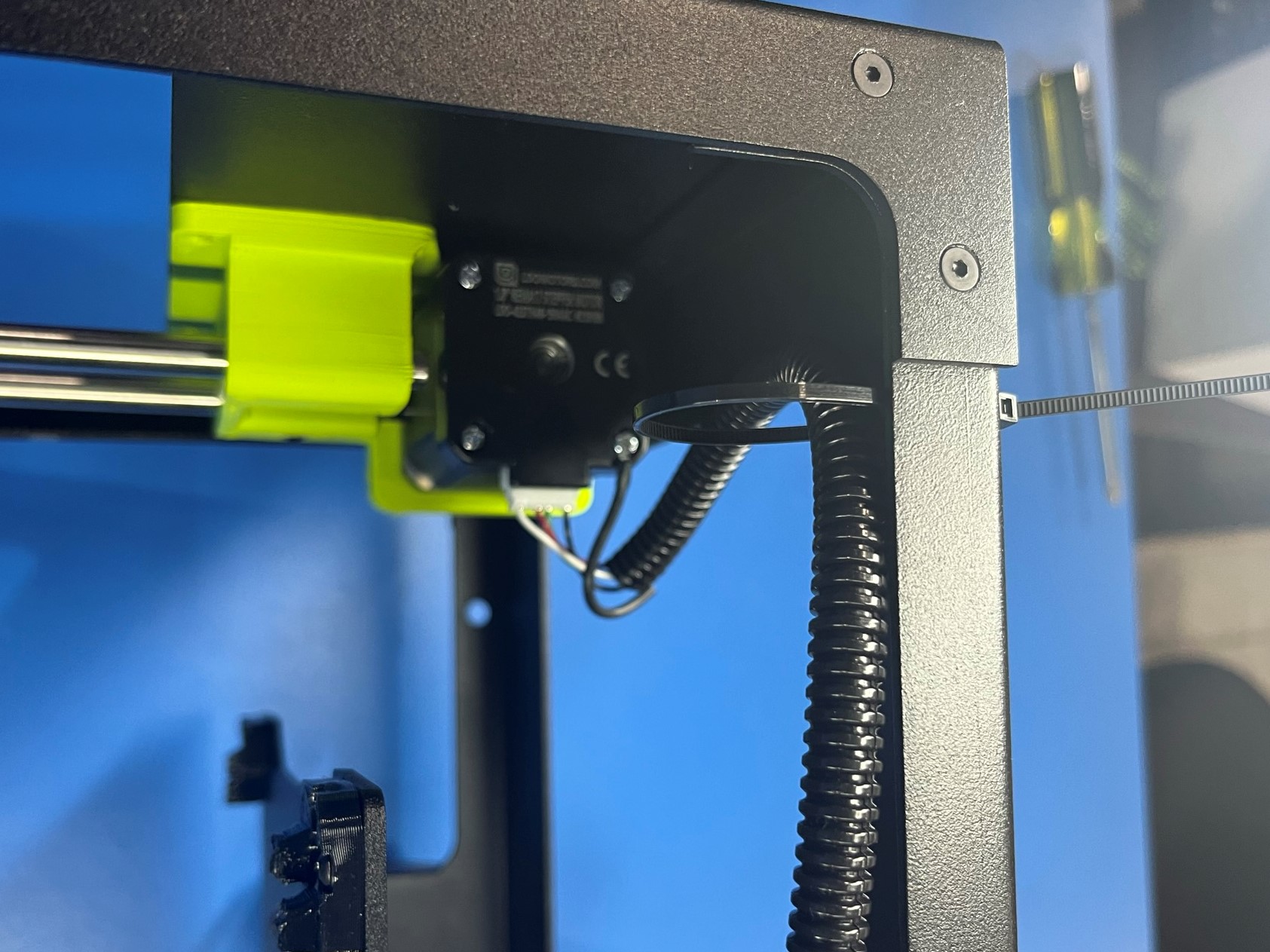
Using a Cable Tie secure all the wire routed through the Lower Strain Relief except the Z-Axis left motor wire
Secure the Y-Axis Motor wire and the Z-Axis right motor wire with a Cable Tie.


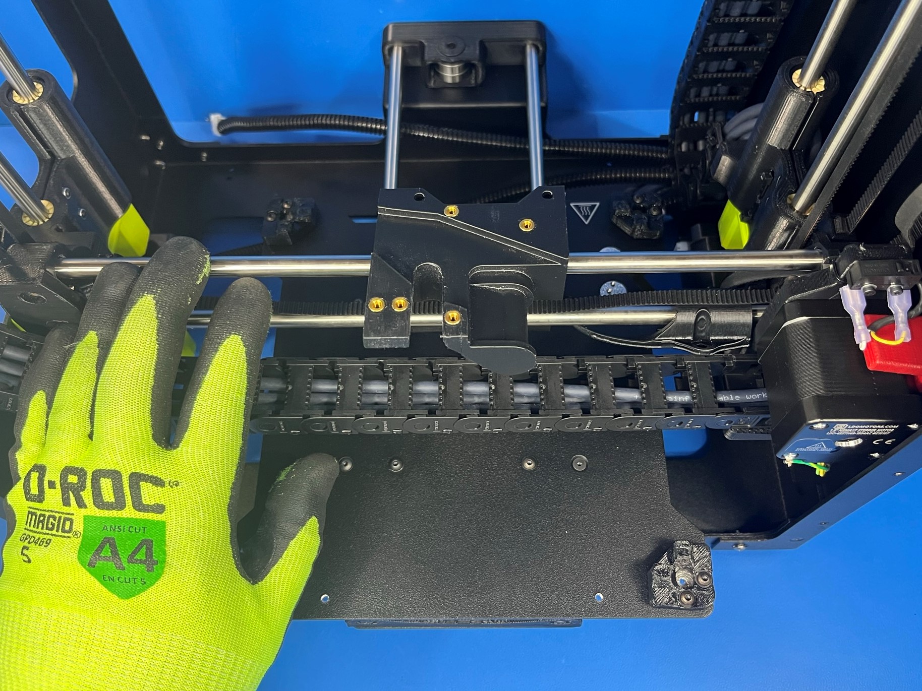

Align the X carriage single bearing holder with the X carriage making sure the three holes in the single bearing holder line up with the three brass inserts on the backside of the X carriage.
Then use 3x M3x6 BHCS [HD-BT0140] with M3 washers [HD-WA0038] secure the single bearing holder to the X carriage.
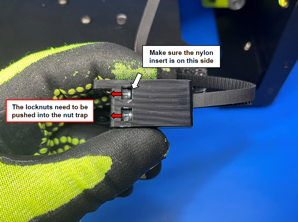
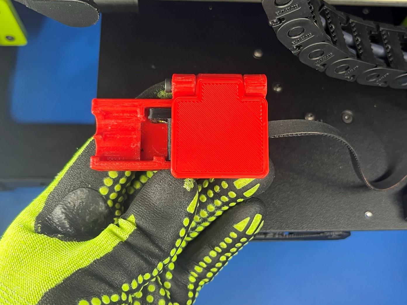
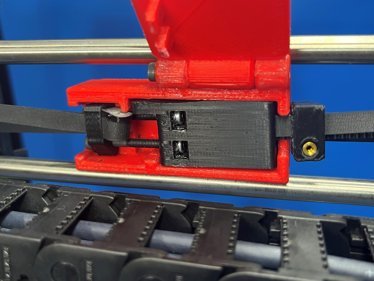
Place 2x M3 locknuts [HD-NT0001] inside the adjustable X axis belt mount, the nylon insert should be on the side that the belt is connected to.
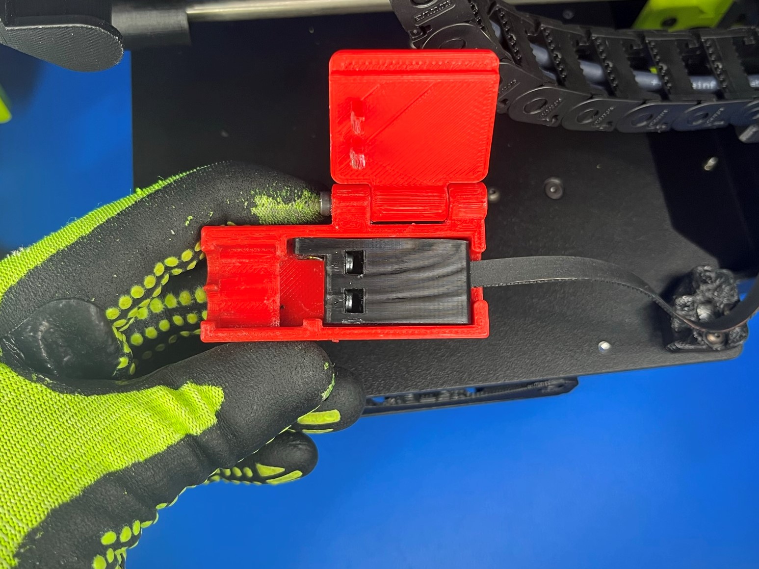
Once the nuts are in the two hole use a flat head screw drivers to tuck them under the print surface inside the nut trap. Place the adjustable X axis belt mount inside the belt mount jig and close the lid.
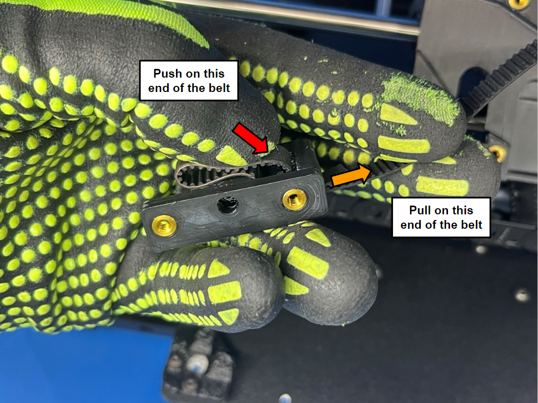
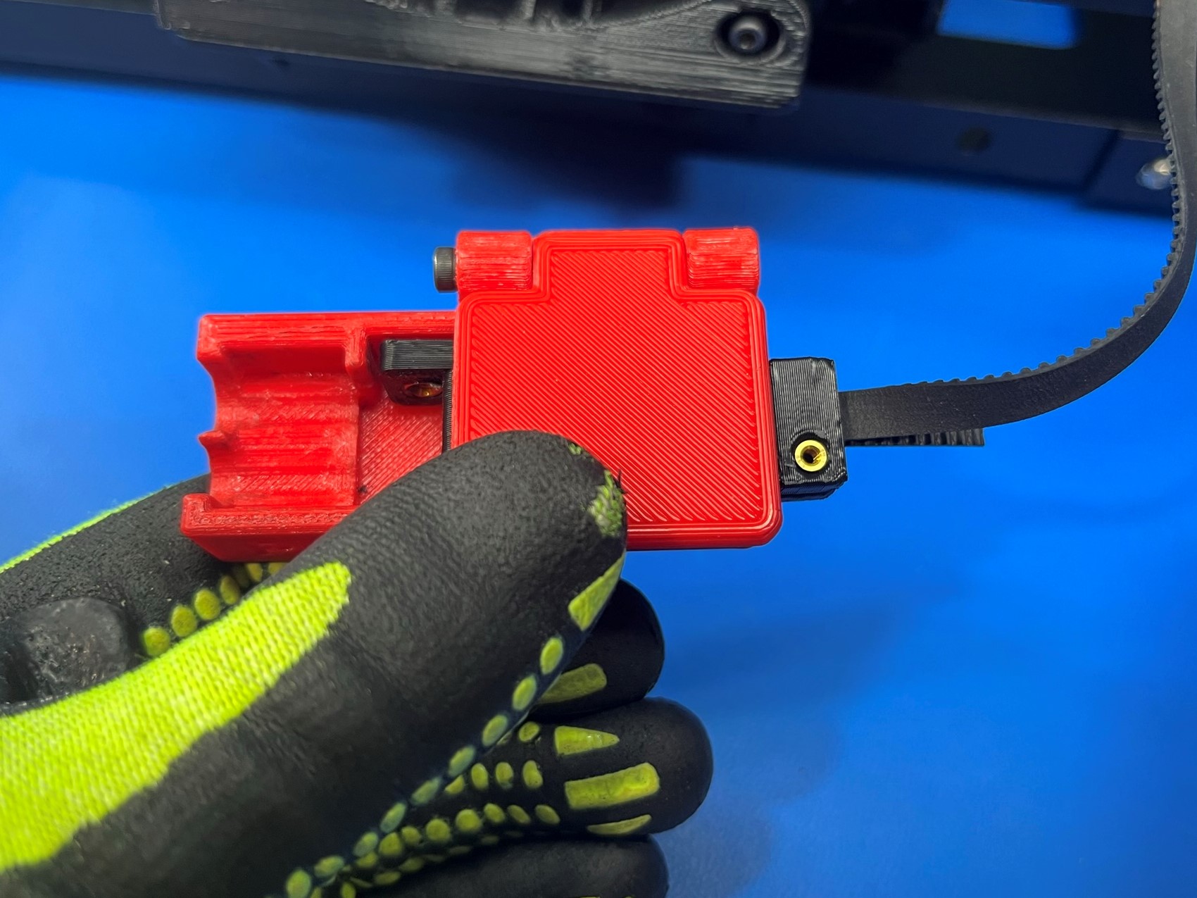
Now slide 2x M3x30 SHCS [HD-BT0042] with M3 washers [HD-WA0038] through the belt tension split collar that's attached to other end of the belt. Pull the belt tension split collar over to the belt mount jig and place it between the tabs at the end of the jig. Note: You should have to stretch the belt for it to reach the end of the jig.
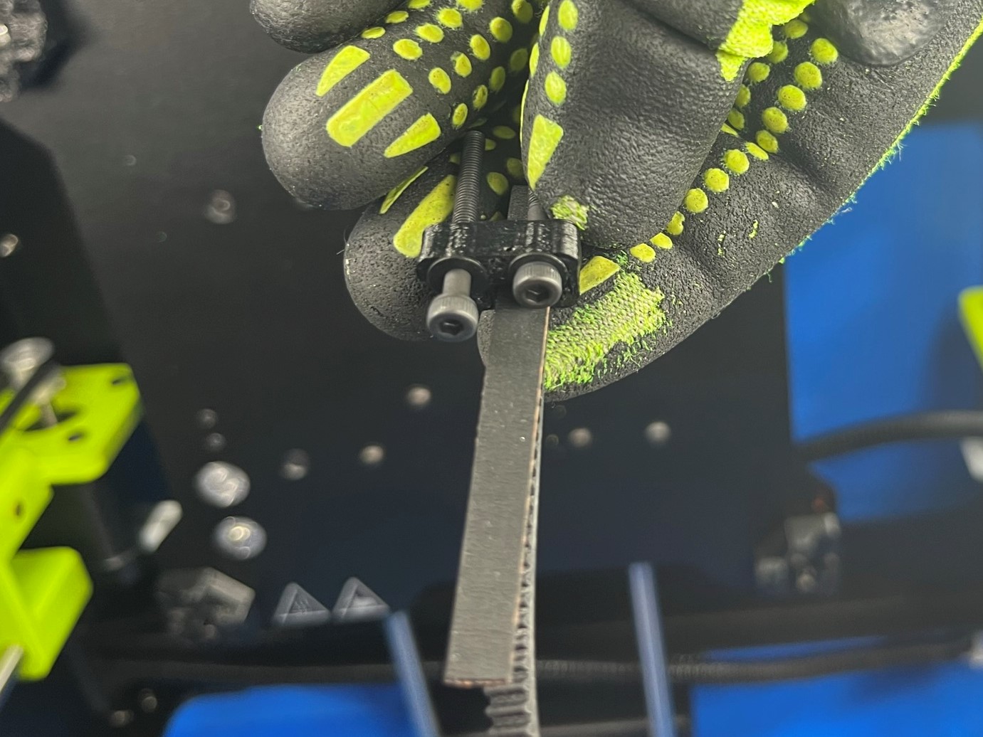
Then align the screw with the locknut inside the adjustable X axis belt mount. Tighten both screws just enough so that the screw reached the nylon insert. You can open the lid to check how far the screws are.
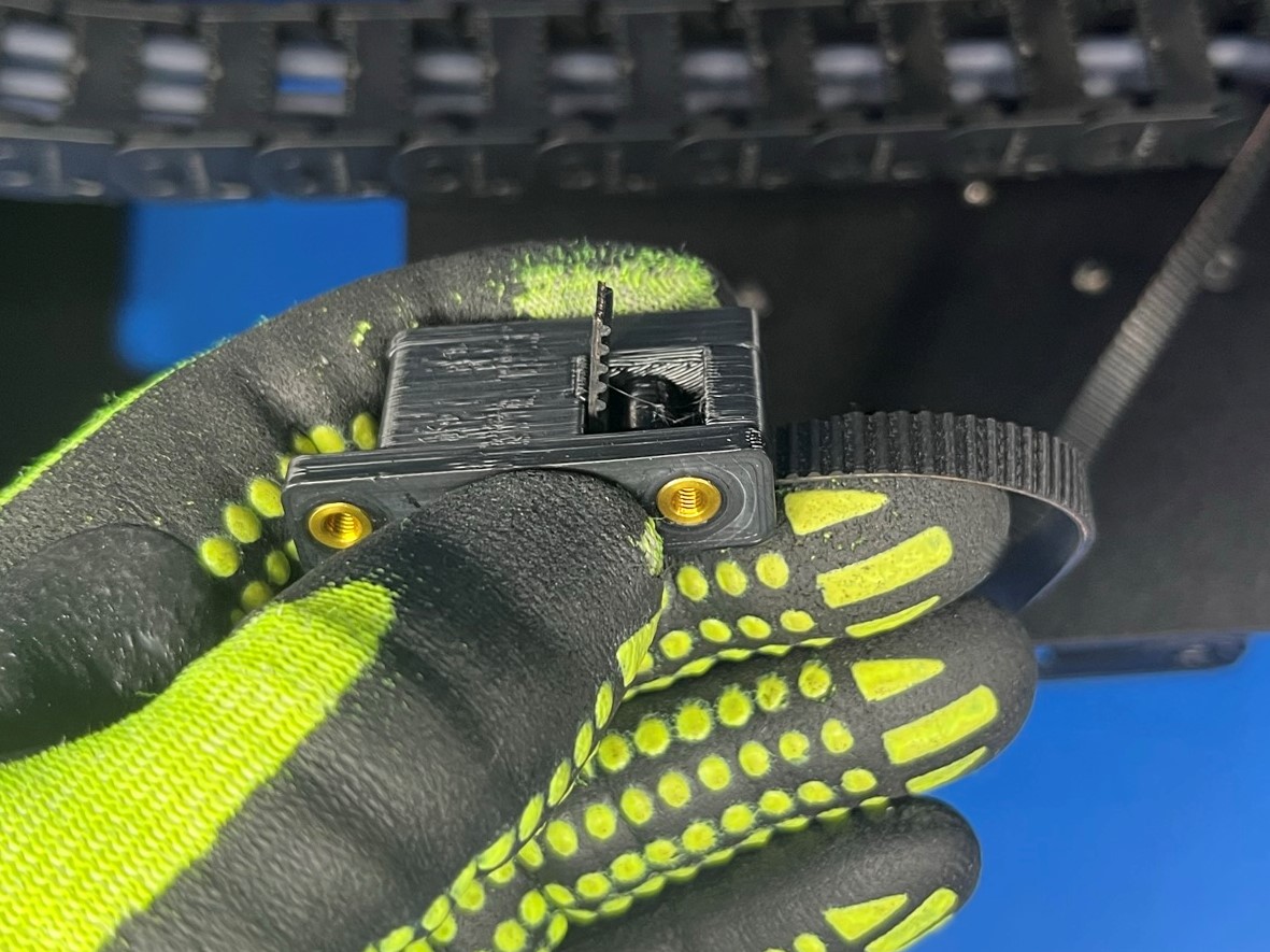
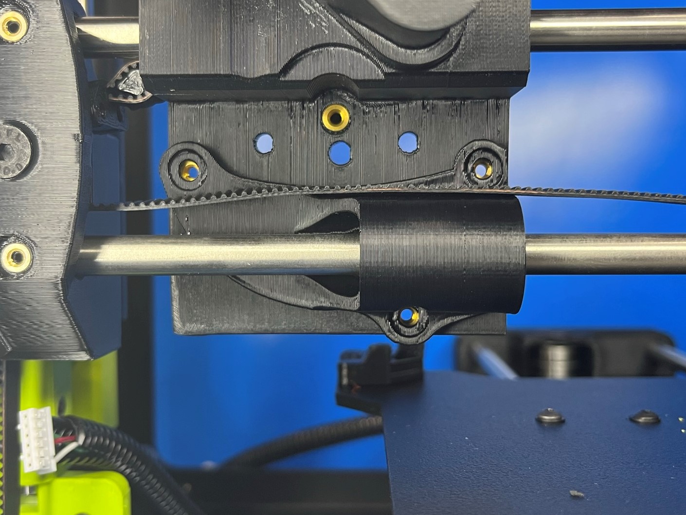
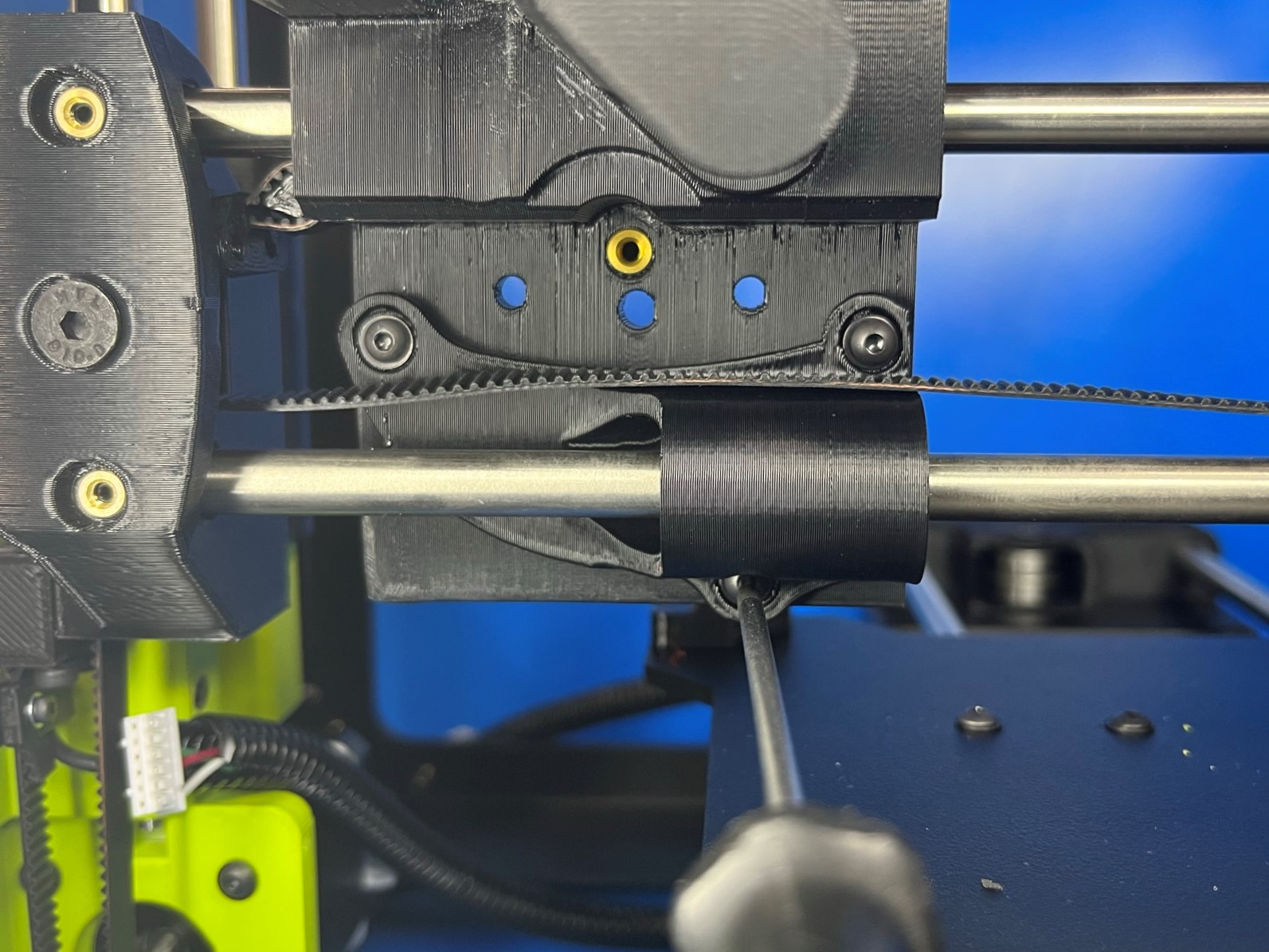
Now slide U channel belt clamp [PP-GP0680] around the end of the belt that is connected to the adjustable X axis belt mount. make sure the brass insert is facing up and away from the X carriage.
Then use a M2x10 SHCS [HD-BT0107] with a M2 washer [HD-WA0012] to secure the U channel belt clamp to the belt.
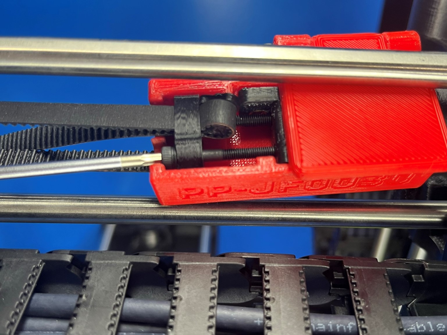
Once the U channel belt clamp is attached to the belt remove the jig and align the adjustable X axis belt mount with the holes on the X carriage. Once they are aligned attach the belt to the X carriage using 2x M3x10 FHCS [HD-BT0116]


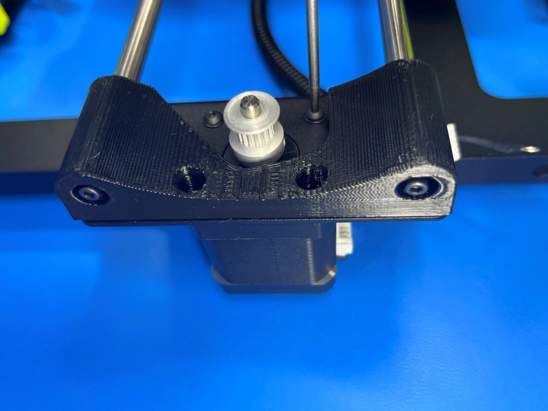
Use the Y motor jig to attach timing pulley [HD-MS0033] to the shaft on the NEMA 17 stepper Motor [EL-MT0068]. Make sure one of the set screw is aligned with the flat side of the motor shaft torque the set screws to 3 in*lbs.
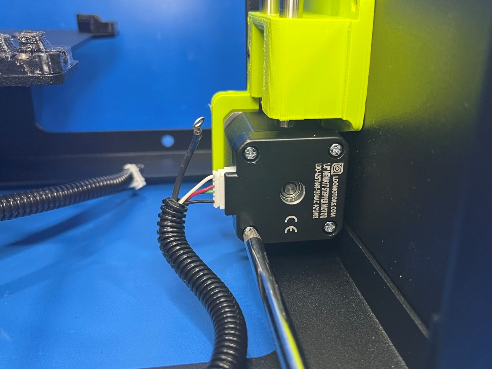
Now use 4x M3x6 BHCS [HD-BT0140] with M3 washers [HD-WA0038] to attach the motor to the bottom frame plate. Make sure the motor connector is facing the left frame plate.
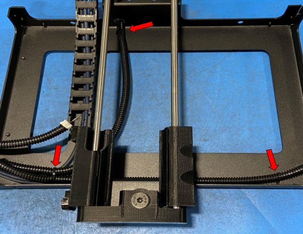
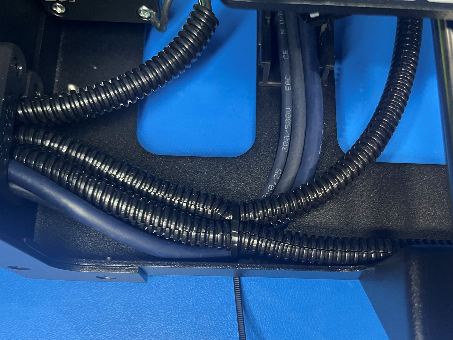
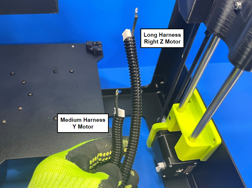
There should be three motor harnesses that are routed through the lower strain relief. The short harness is for the left Z motor, the medium length harness is for the Y motor, and the long harness is for the right Z motor.
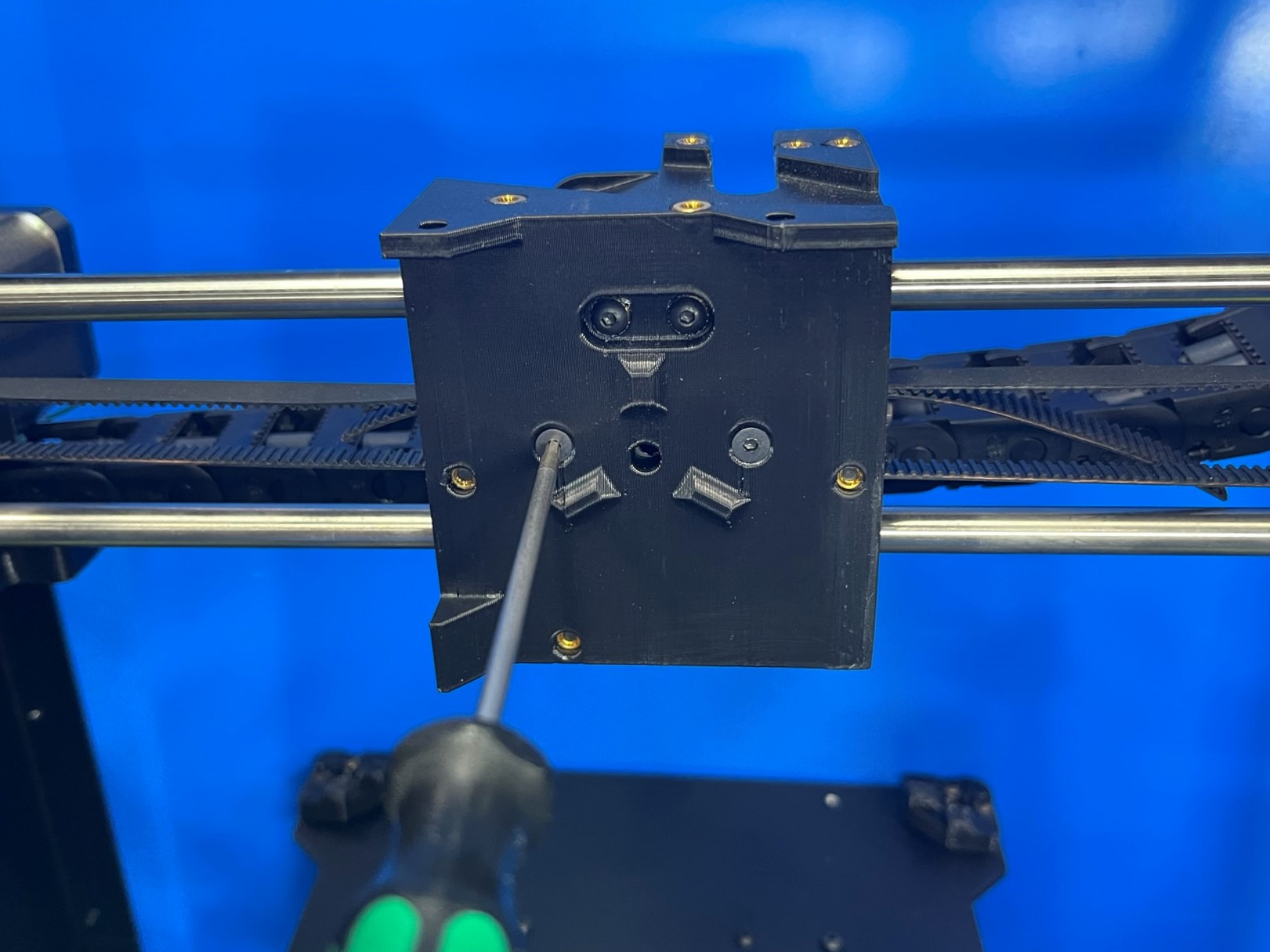
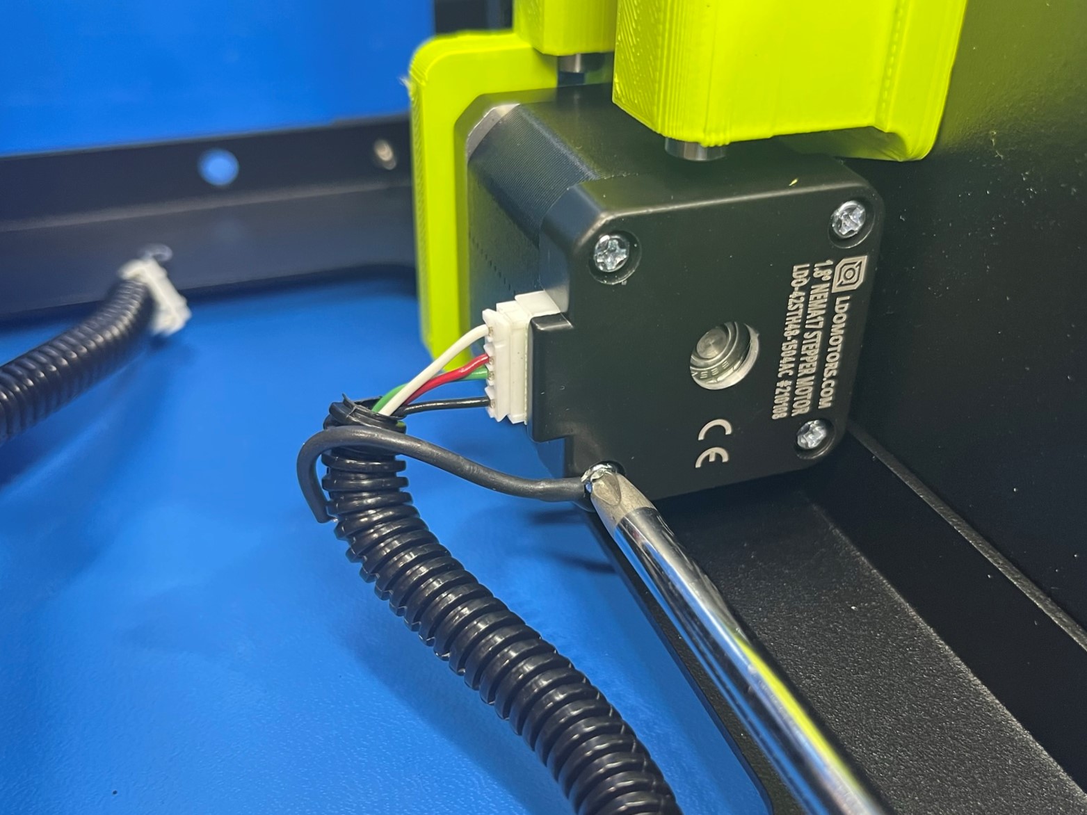
Once you have identified all the harnesses connect the right Z motor, and use a screw driver to remove the bottom left screw on the bottom side of the motor. Once the screw is fully removed slide the ring, that's attached to the ground wire, over the screw and replace the screw in the motor.
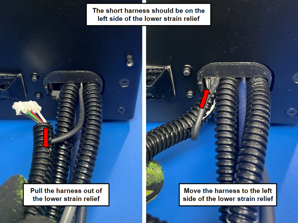
Now make sure the short harness (left Z motor) is on the left side of the lower strain relief. If the harness is not on the left side, pull the harness back through the lower strain relief and rearrange the harnesses then push it back through the strain relief.
Then connect the left Z motor using the same technique as the right Z motor. The only difference is the ground wire will be attached to the bottom right screw.
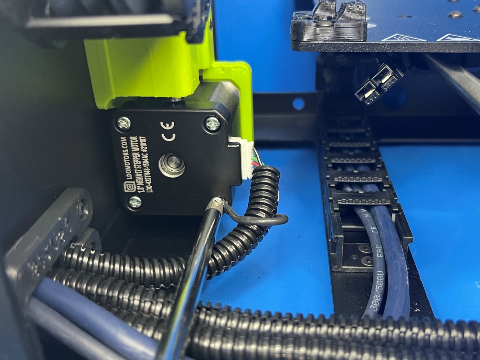
Take the medium harness (Y motor) and route it under the Y axis and through the hole on the back of the bottom frame plate. Then flip the frame of the printer so that the bottom is facing you and it's resting on the right frame plate.
Now connect the Y motor and place the ground wire under the top left screw.


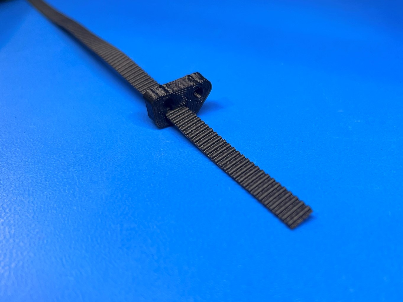
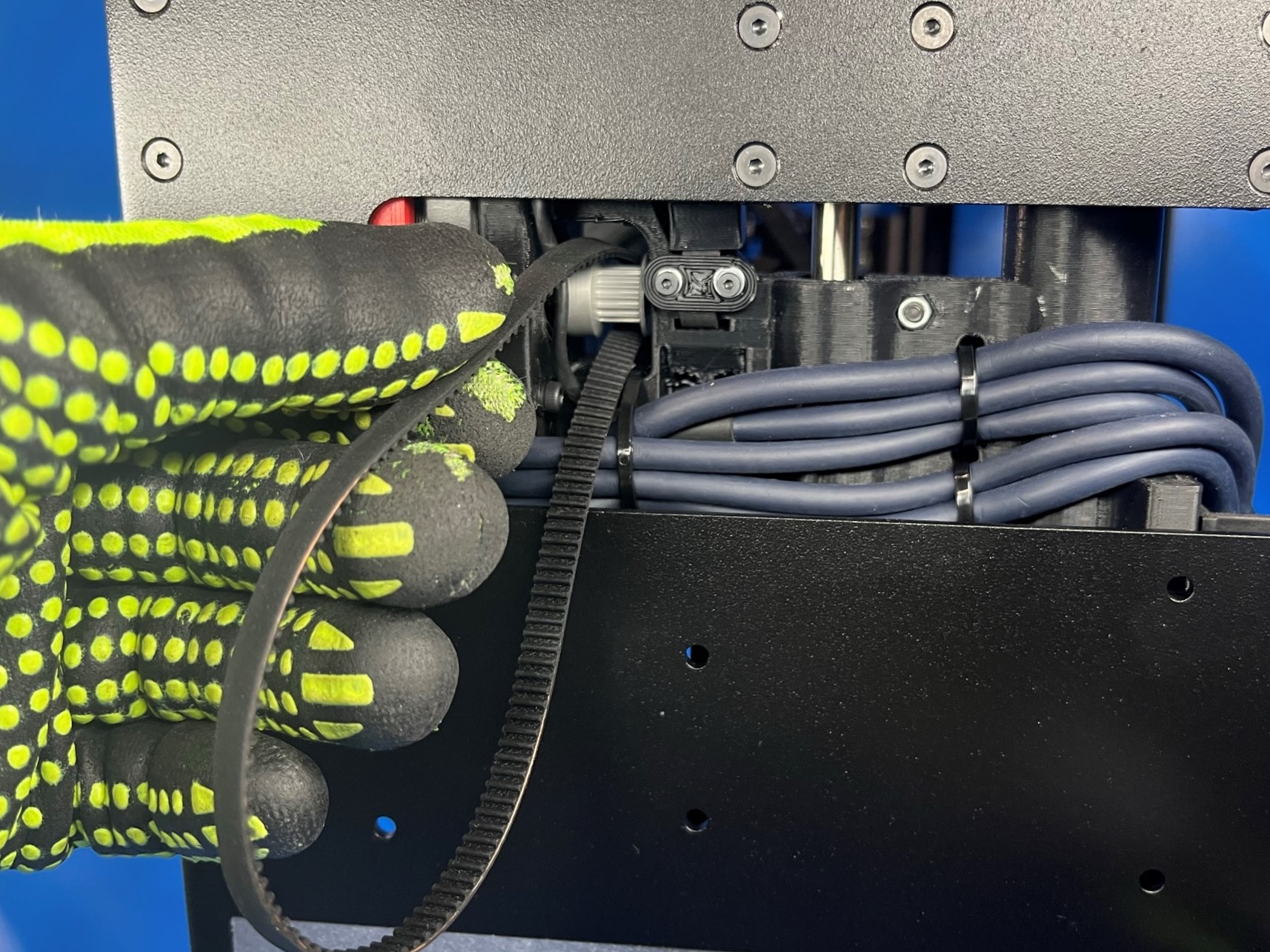
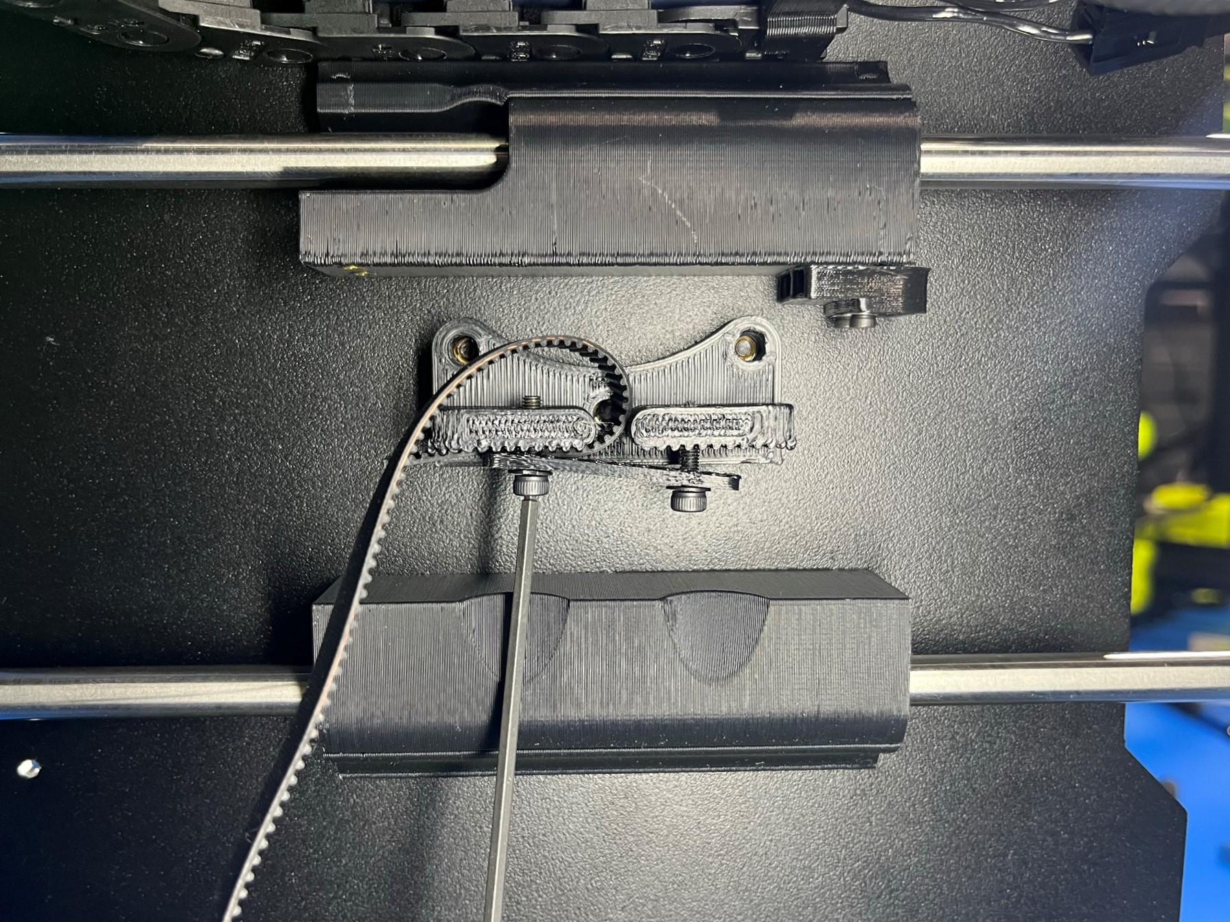
Then cut 1x single sided neoprene belt [HD-BL0033] and wrap one end around the Y belt clamp. Then tighten the one side of the belt clamp to hold the belt in place. Now route the belt around the timer pulley that's connected to the motor.
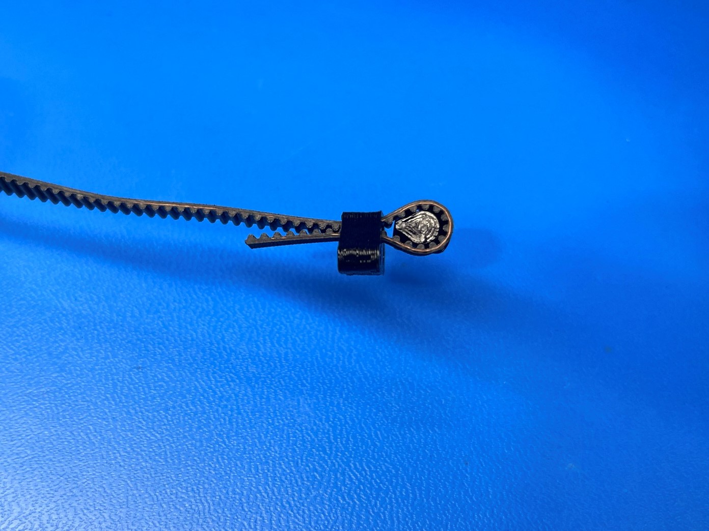
Pull the belt across the Y axis and wrap it around the bearing that attached to the Y idler. Bring the end of the belt back to the Y belt mount and wrap it around and slide it under the Y belt clamp plate.
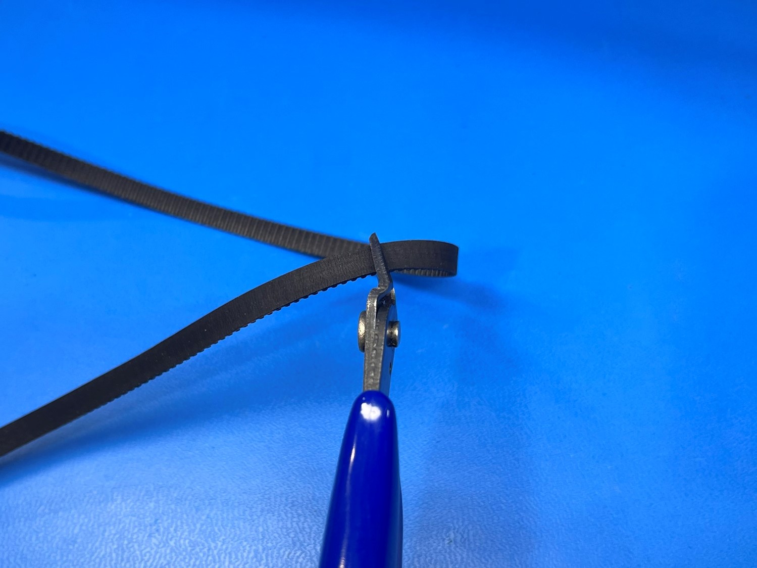
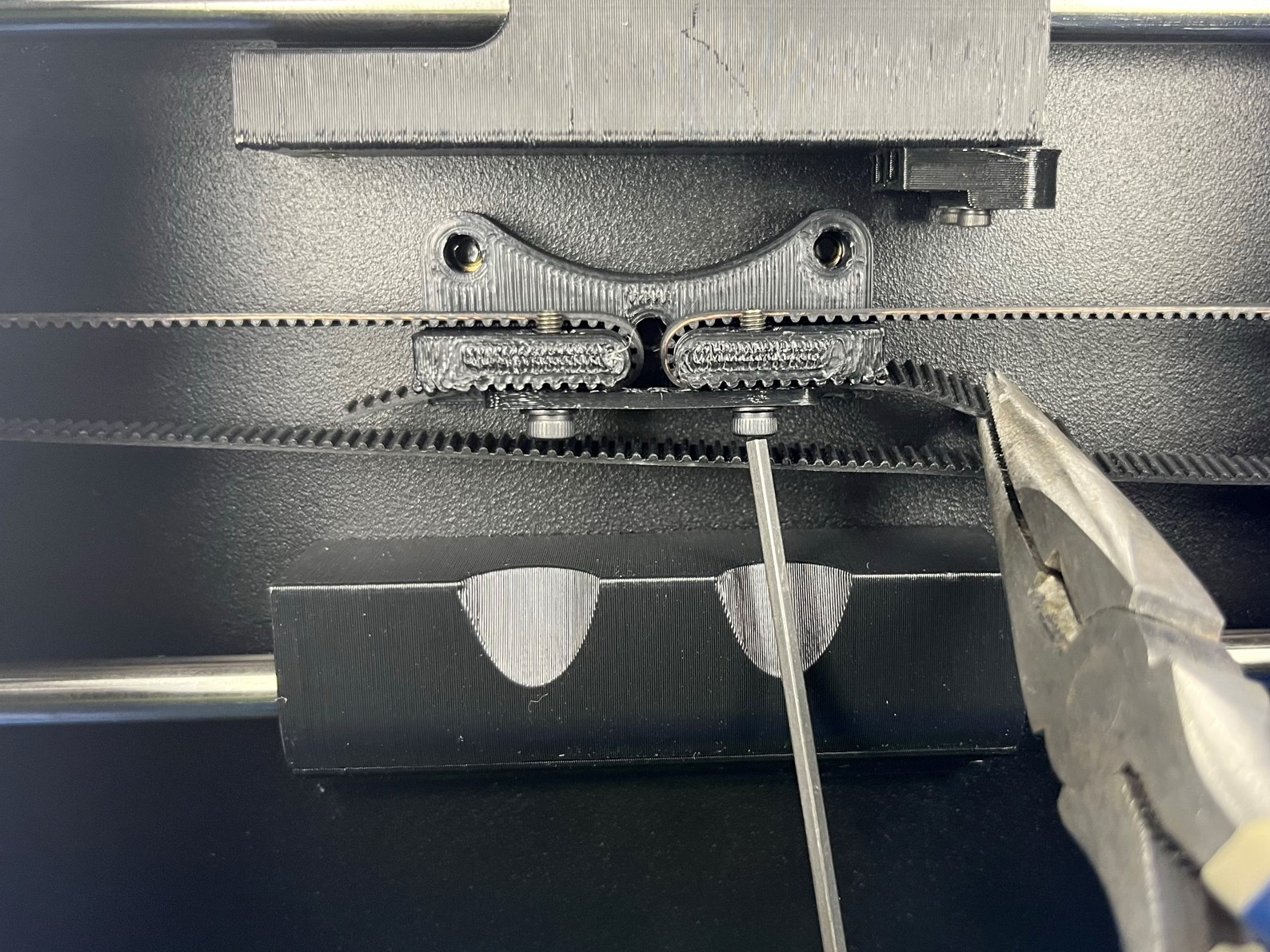
Using a pliers pull the belt tight and tighten the belt clamp. Make sure both belt clamp screws are tightened and the belt ends are secure.


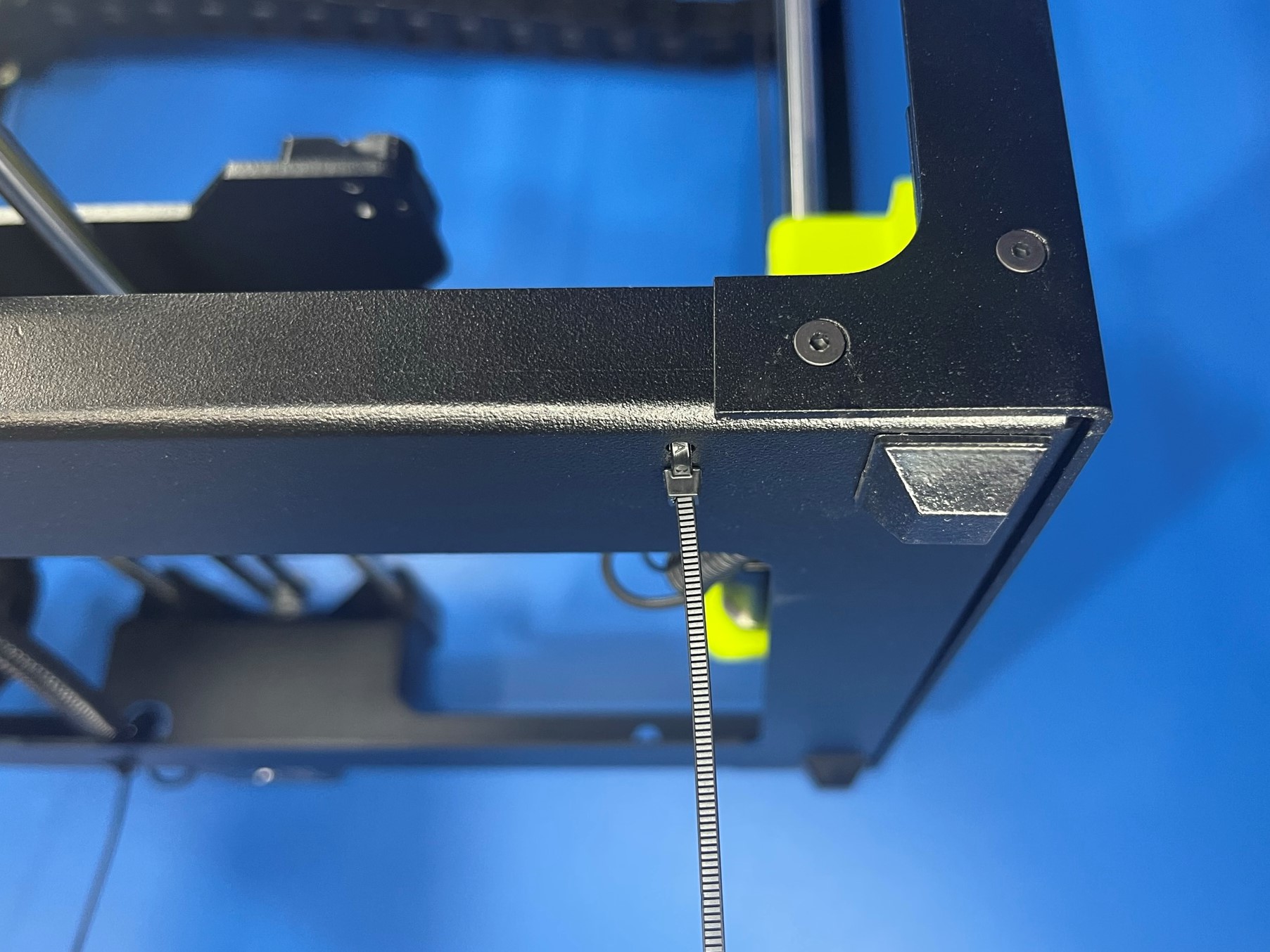
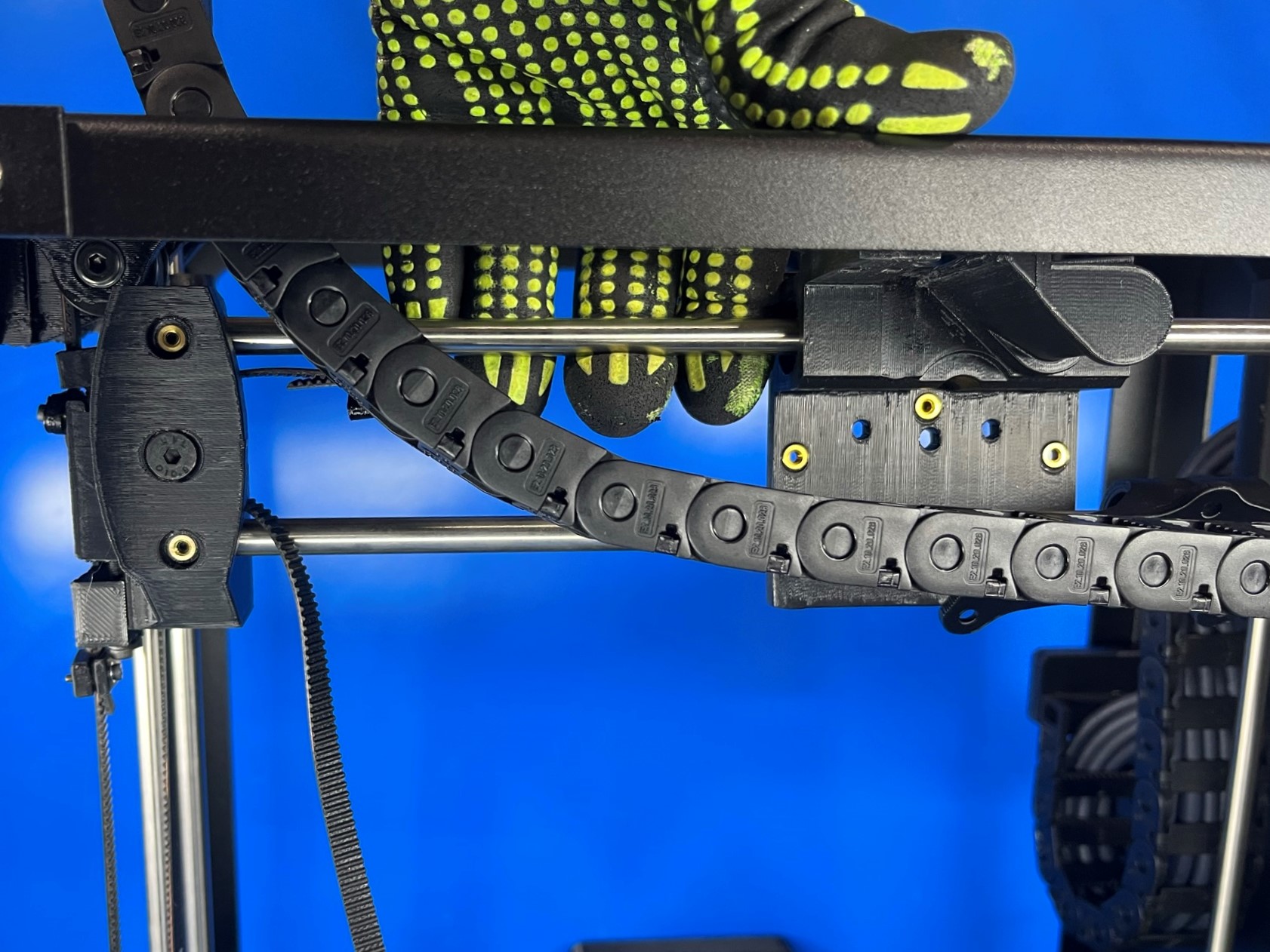
Keep the printer resting on the right frame plate when placing the cable ties.
Follow the Cable Tie Placement Guide when installing the 3x cable ties [HD-MS0058]
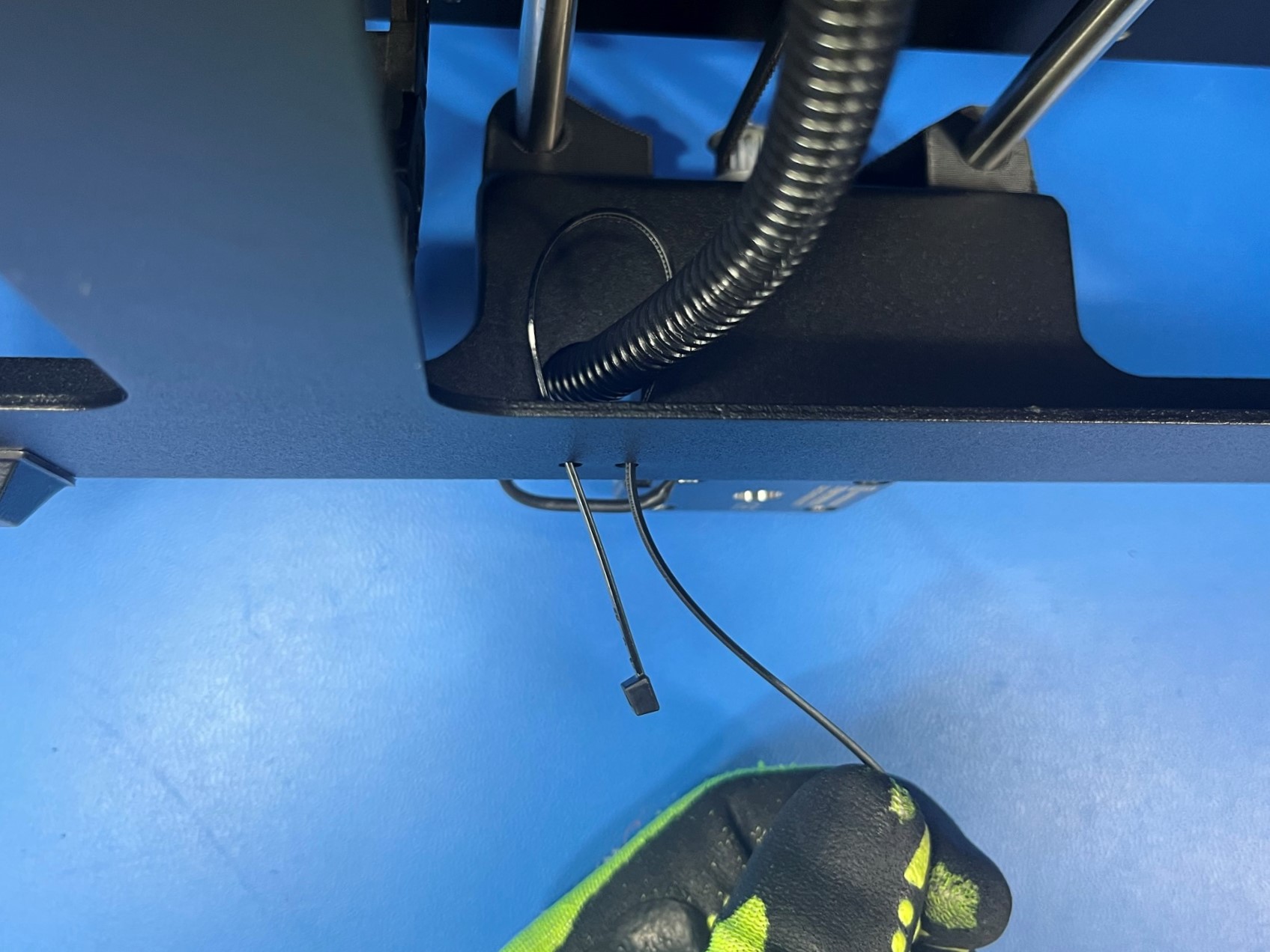
Start by feeding a cable tie through the bottom hole on the left side of the bottom frame plate. Now wrap the cable tie around the Y motor harness and feed it back through the top hole and tighten the cable tie securing the harness to the bottom frame.
Repeat the process for the right Z harness, start with the right hole in the bottom right corner. Then wrap the cable tie around the harness and feed it back through the left hole and tighten.
Repeat the process once again for the last cable tie. Start with the right hole and then wrap the cable tie around the RZ and Y motor harnesses as well as the bed harnesses. Once its wrapped around all the harnesses feed it back through the left hole and tighten. Make sure the Blue and Grey wires lay flat.
Trim all three cable ties and make sure the right Z motor harness is laying flat against the bottom frame plate.