Open HardwareAssembly Instructions
Guides for installation and assembly of the LulzBot line of products made by FAME 3D LLC.
Guides for installation and assembly of the LulzBot line of products made by FAME 3D LLC.
1x- [AS-CB0069] Z-Brake Power Harness
1x- [AS-CB0070] Z-Brake Motor Harness
1x- [AS-CB0082] Chassis Ground Extension
1x- [EL-HR0188] LCD Harness 1
1x- [EL-HR0189] LCD Harness 2, split
4x- [HD-BT0082] M3x16 FHCS, SST
4x- [HD-BT0104] M3x8 BHCS, SST
8x- [HD-BT0128] M3x6 FHCS, Black-Oxide
4x- [HD-BT0137] M3x8 BHCS, Black-Oxide
4x- [HD-BT0140] M3x6 BHCS, Black-Oxide
2x- [HD-BT0206] M3x25 FHCS, Black-Oxide
1x- [HD-BT0210] M3x30 SHCS, Blue-Dyed Zinc
2x- [HD-BT0211] M3x8 SHCS, Blue-Dyed Zinc
3x- [HD-MS0058] 8" Cable Tie
2x- [HD-MS0463] Thermal Gap Filler
2x- [HD-NT0001] M3 Nyloc Nut
1x- [HD-WA0035] M3 External Tooth Lock Washer
7x- [HD-WA0038] M3 Washer
1x- [PC-AS0054] EinsyRetro 1.0a
1x- [CB-BD0096] Z Brake
1x- [PP-GP0503] USB Support
1x- [PP-GP0504] Heatsink Frame
1x- [PP-GP0505] Z Brake Board Mount
1x- [PP-MP0210] Heatsink
LCD Screen
SE Toolhead
Electronics Case
Final Mechanical Assembly

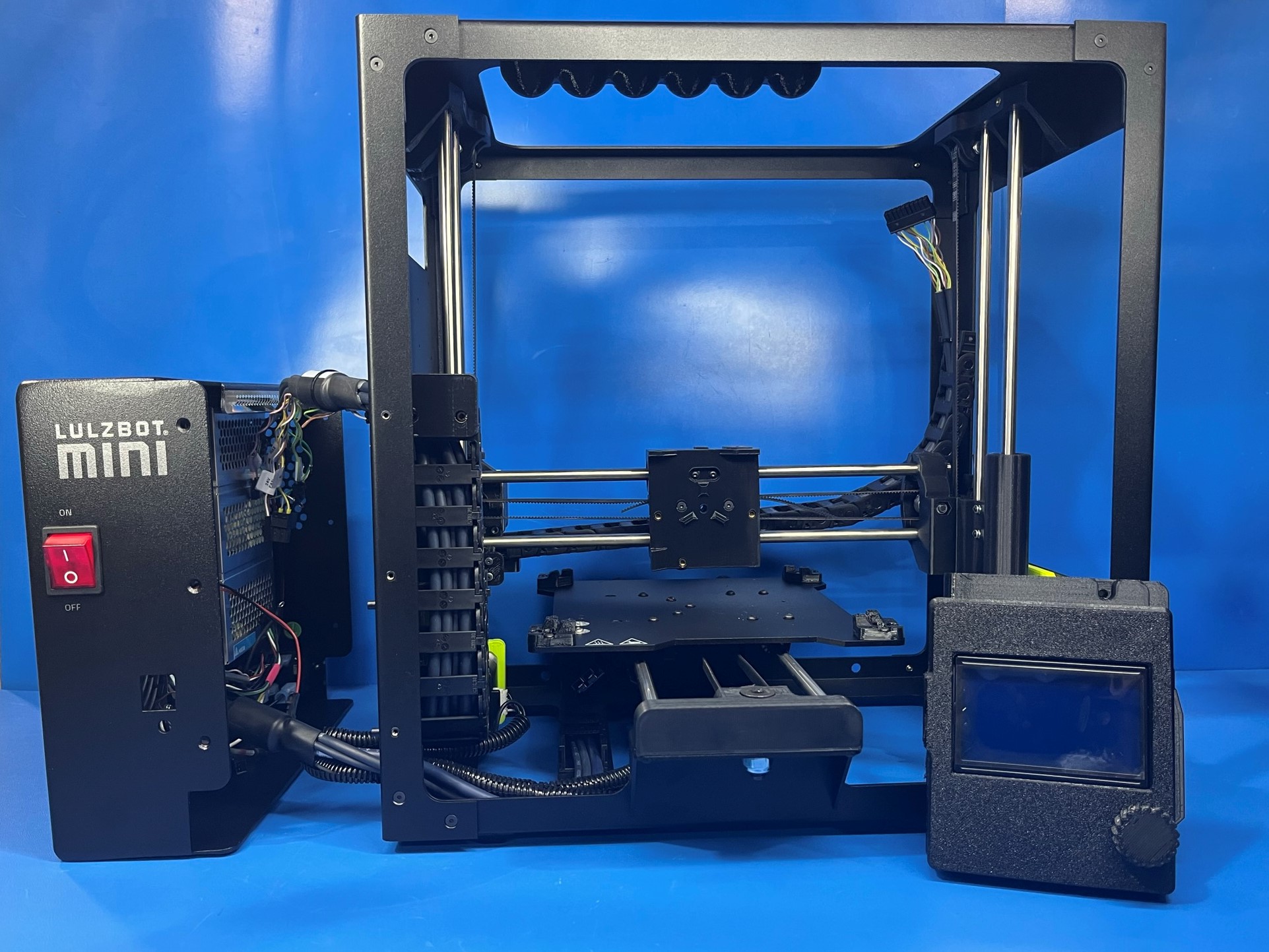
Set the printer on the right frame plate with left frame plate facing up and the harnesses closest to you.
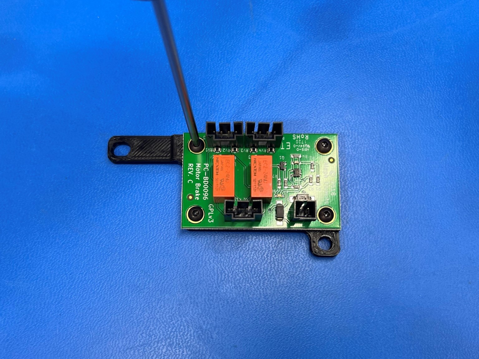
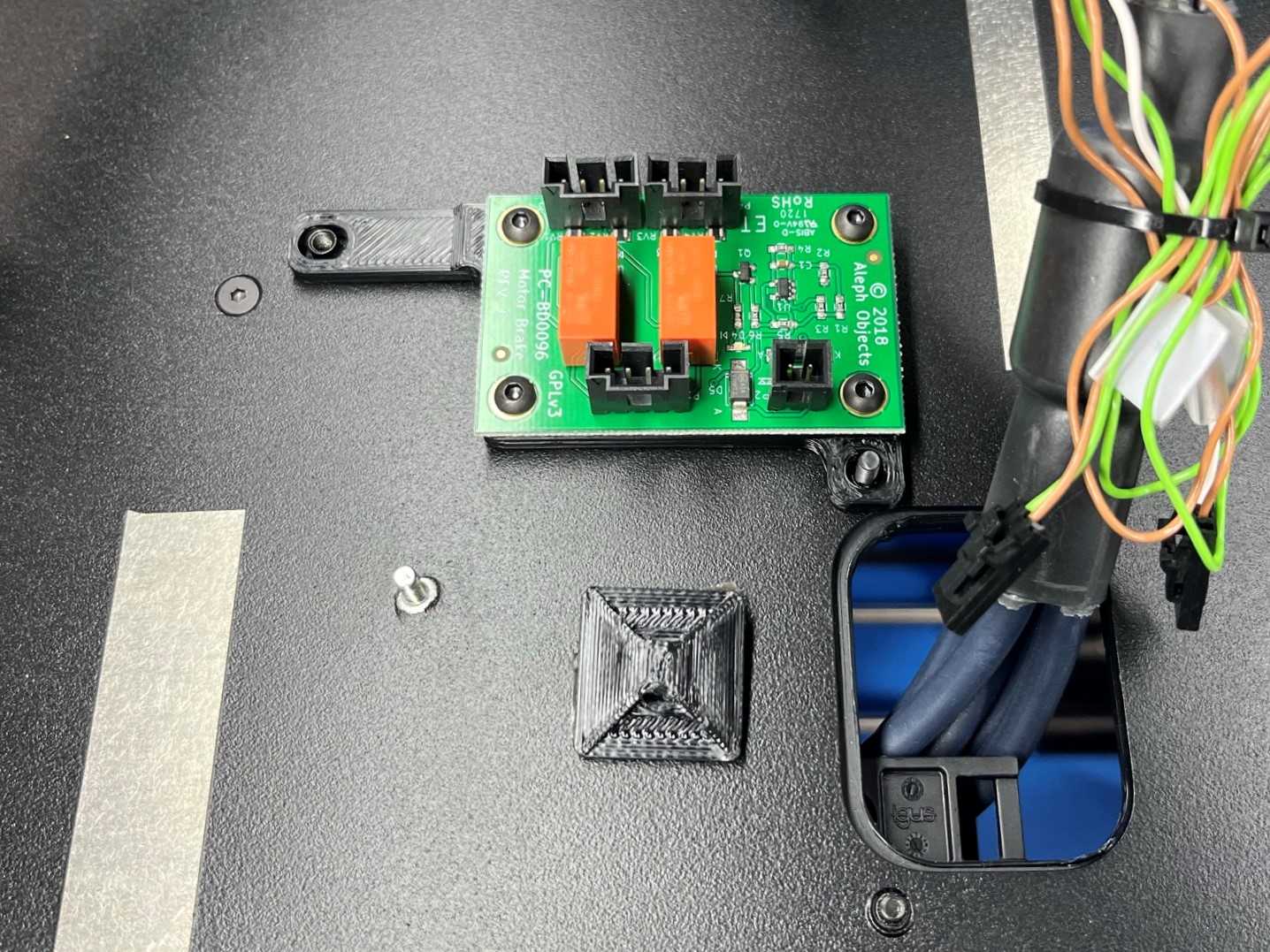
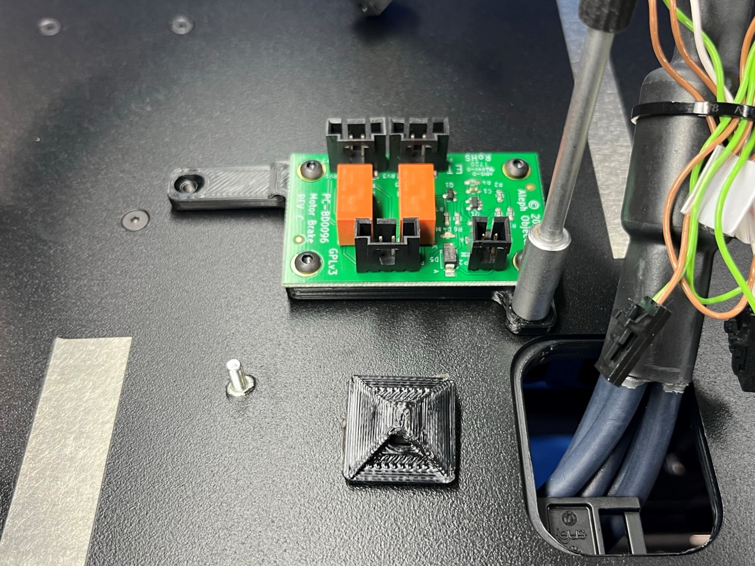
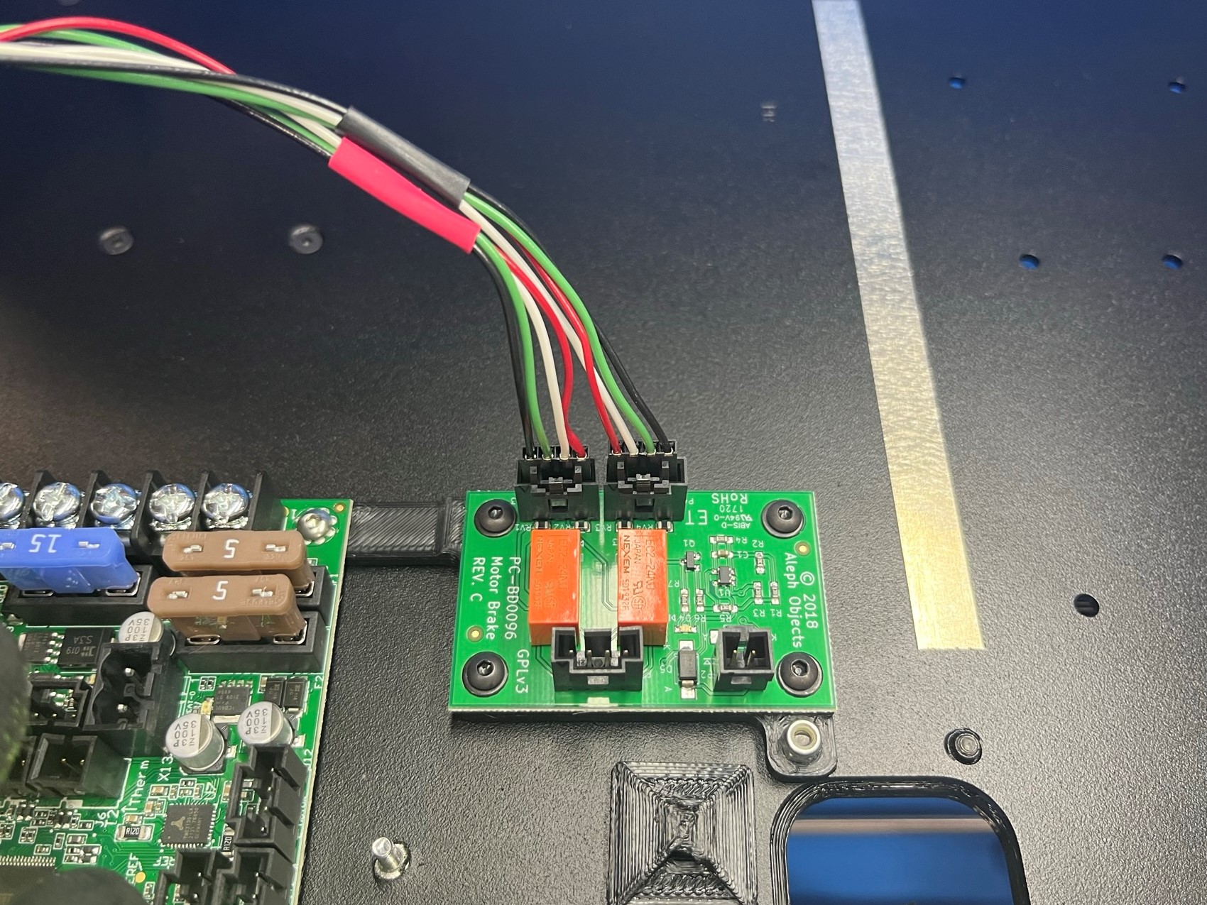
Place the Z brake [PC-BD0096] over the Z brake board mount [PP-GP0337] making sure the side with the two motor ports is on the same side as the longer leg. Once the Z brake is aligned use 4x M3x6 BHCS [HD-BT0140] with M3 washers [HD-WA0038] to secure the Z break to the Z break board mount.
Now place the Z brake board mount on the left frame plate make sure the shorter leg is around the long upper strain relief bolt. Once the part is aligned use a M3 locknut [HD-NT0001] to mount the Z break board mount to the longer upper strain relief bolt.
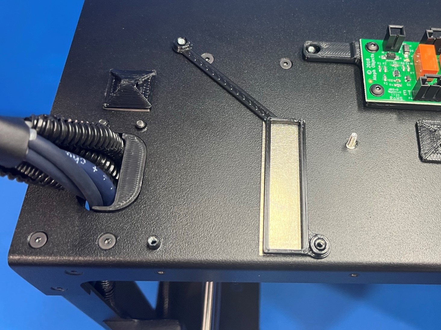
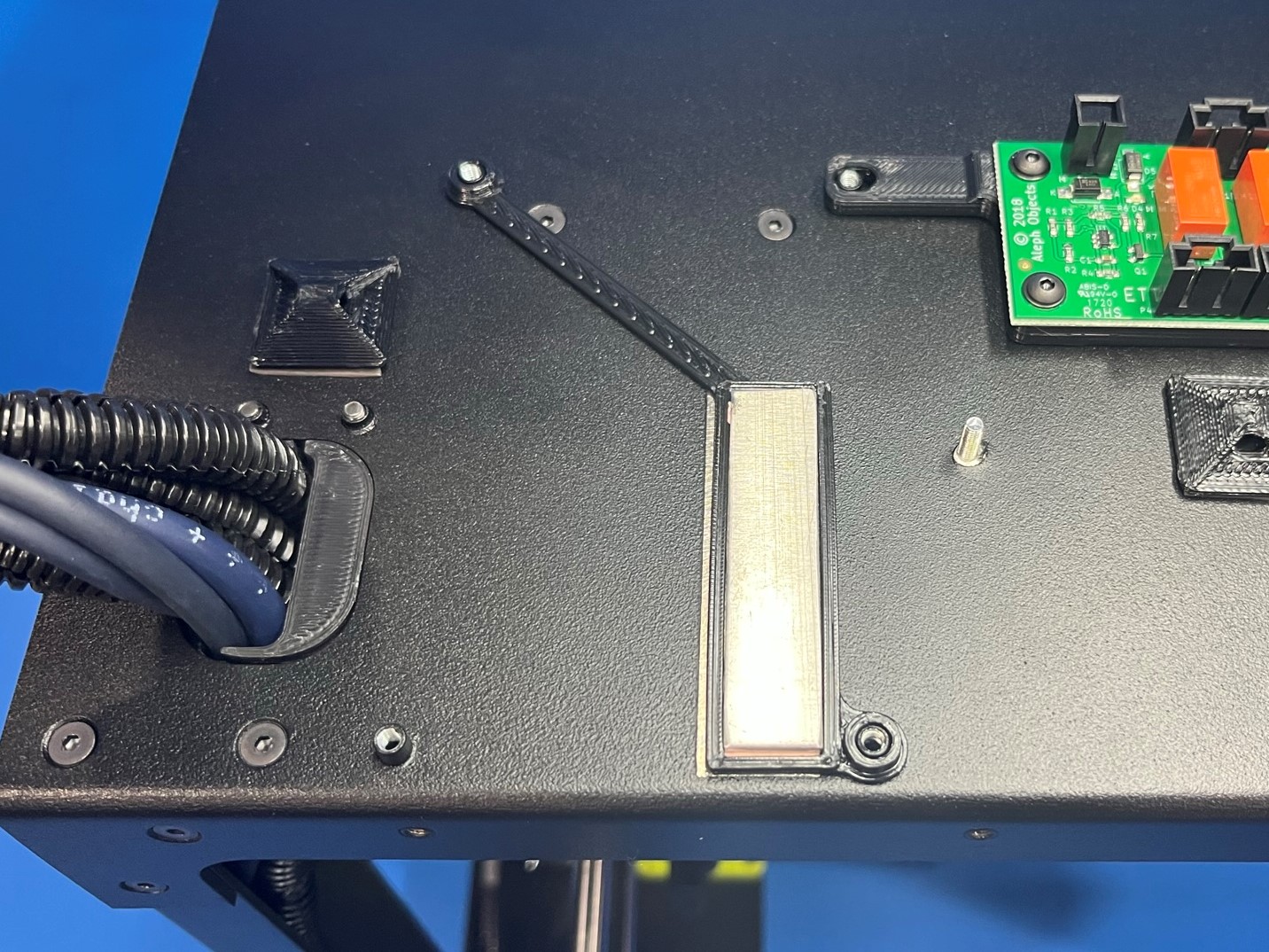
Then take the heatsink frame [PP-GP0338] and place it on the printer making sure the plastic part outlines the sliver rectangle on the left frame plate. Make sure both holes are around the pegs on the left frame plate.
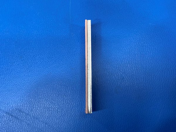
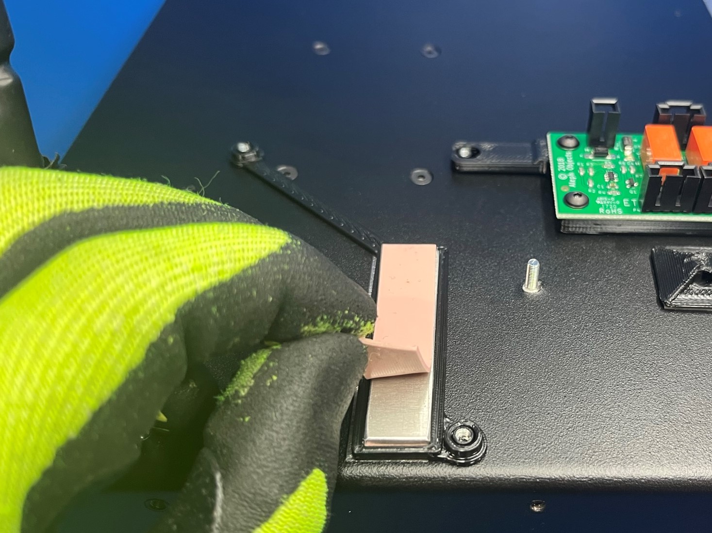
Place one segment of the thermal gap filler [HD-MS0463] on one side of the heatsink [PP-MP0210], try to perfectly cover the side of the heatsink. Then place the side of the heatsink that has the thermal gap filler in the middle of the heatsink frame, covering the silver rectangle. Then take the second segment of the thermal gap filler and place it over the top side of the heatsink.
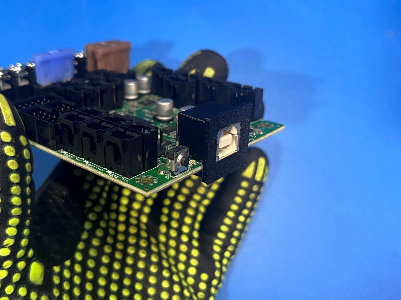
Remove the Einsy retro board [PC-AS0054] from the anti-static packaging. Then slide the USB support [PP-GP247] over the USB on the retro board. You may need to sand the sides of the USB support if it can't slide all the way over the USB port.
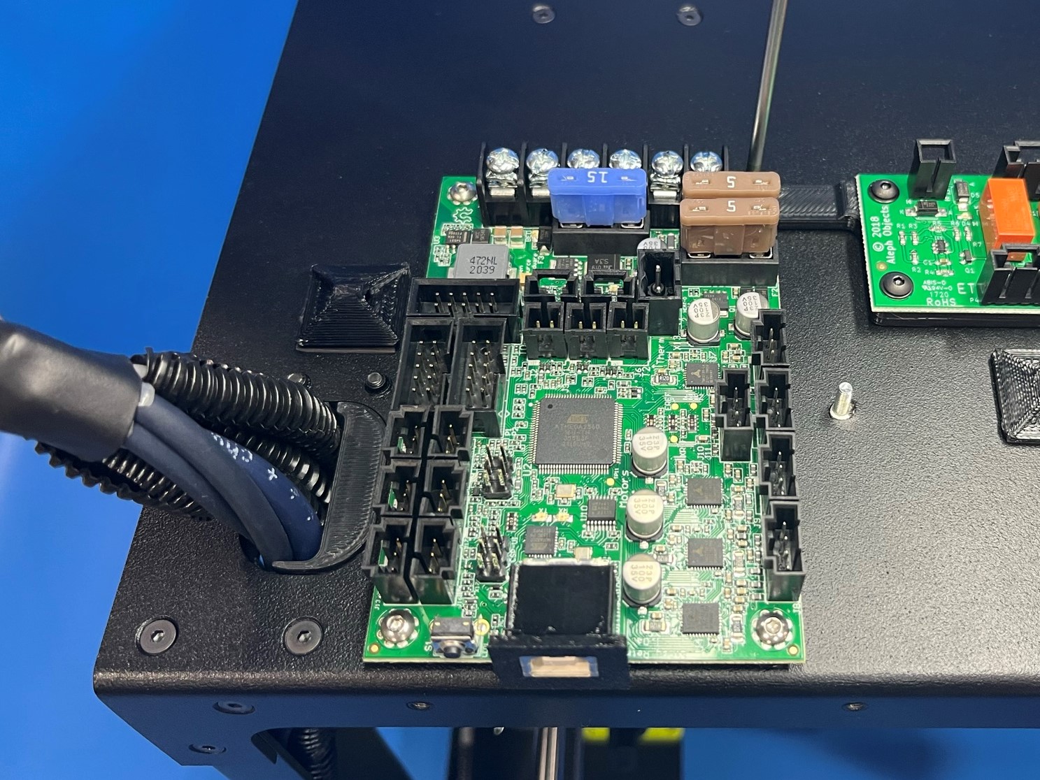
Now place the retro board over the four threaded pegs with the USB overhanging the edge of the frame plate.
Then use 4x M3x8 BHCS [HD-BT0104] to secure the retro board to the left frame plate.
DO NOT OVERTIGHTEN THE BOLTS, IT COULD BREAK THE BOARD
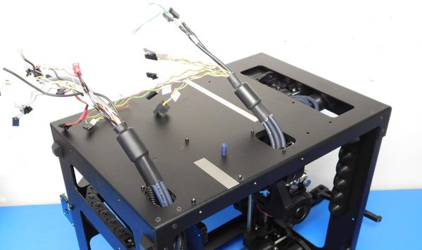
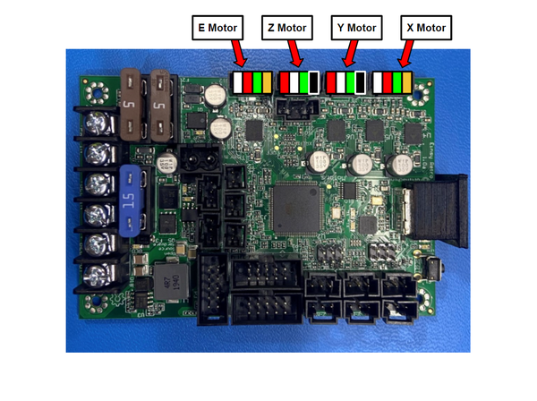
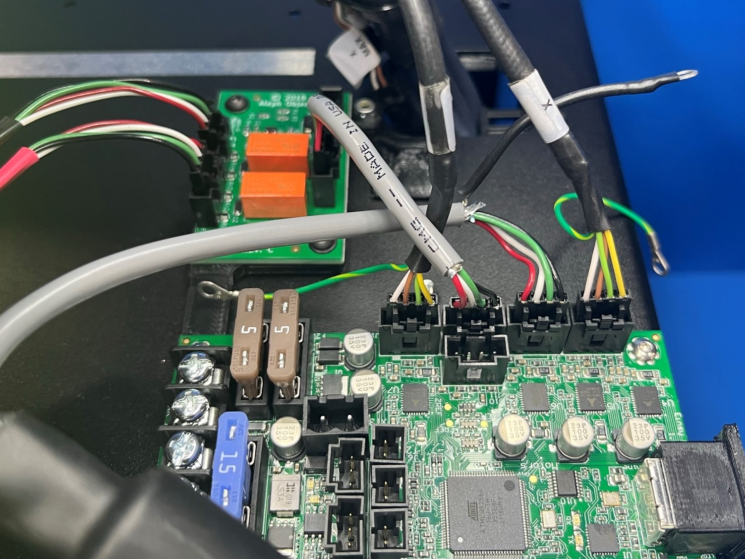
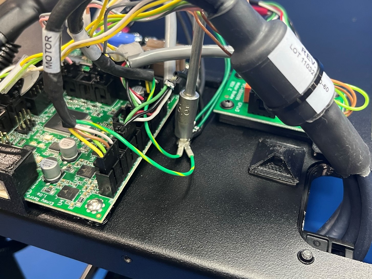
Connect the motor harness to the retro board as follows:
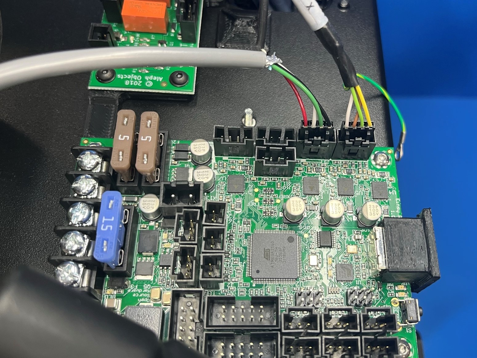
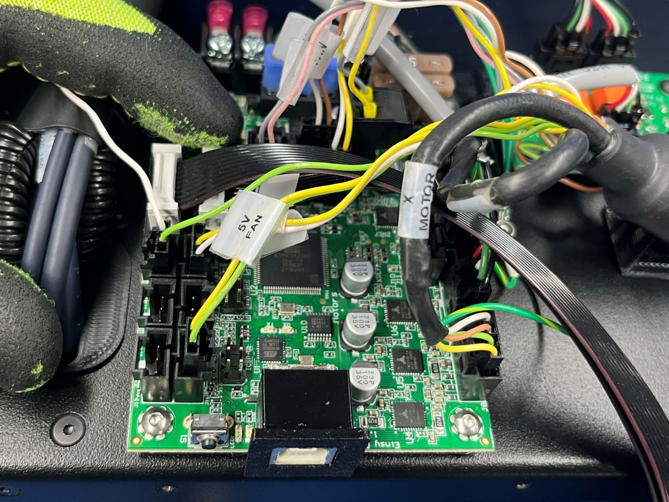
1. Locate the wire harness labeled “X Motor” and connect it to the board as pictured.
2. Locate the Y motor wire harness with a grey covering . Connect it to the board as pictured, to the left of the X motor connection.
3. Locate the wire harness labeled “E Motor” and plug it into the board as pictured.
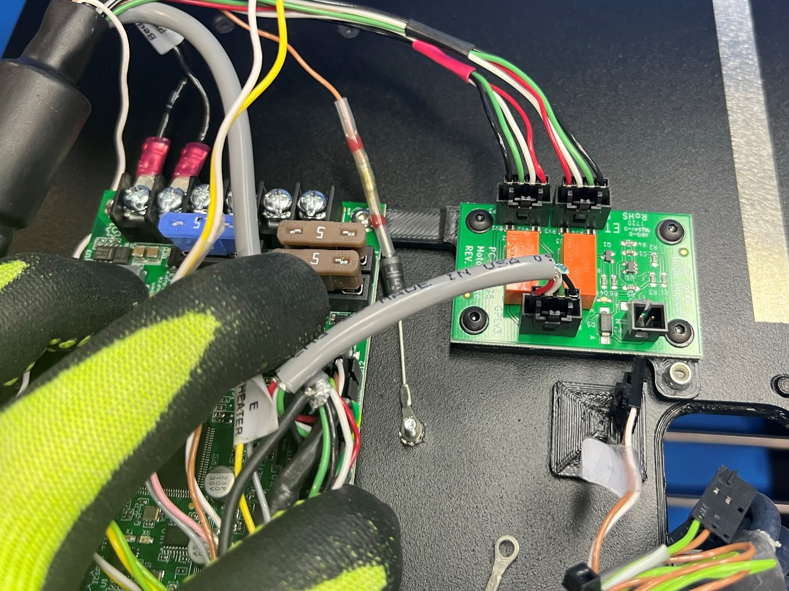
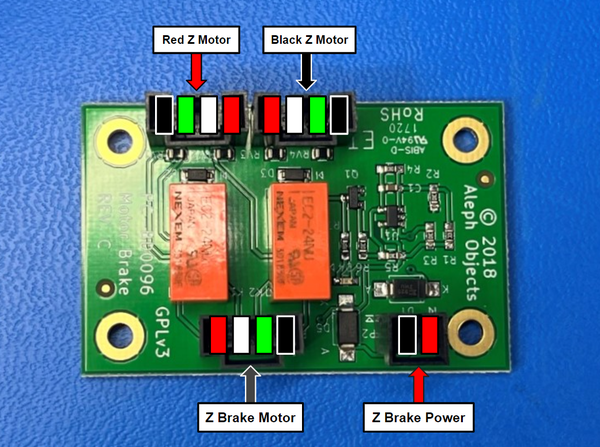
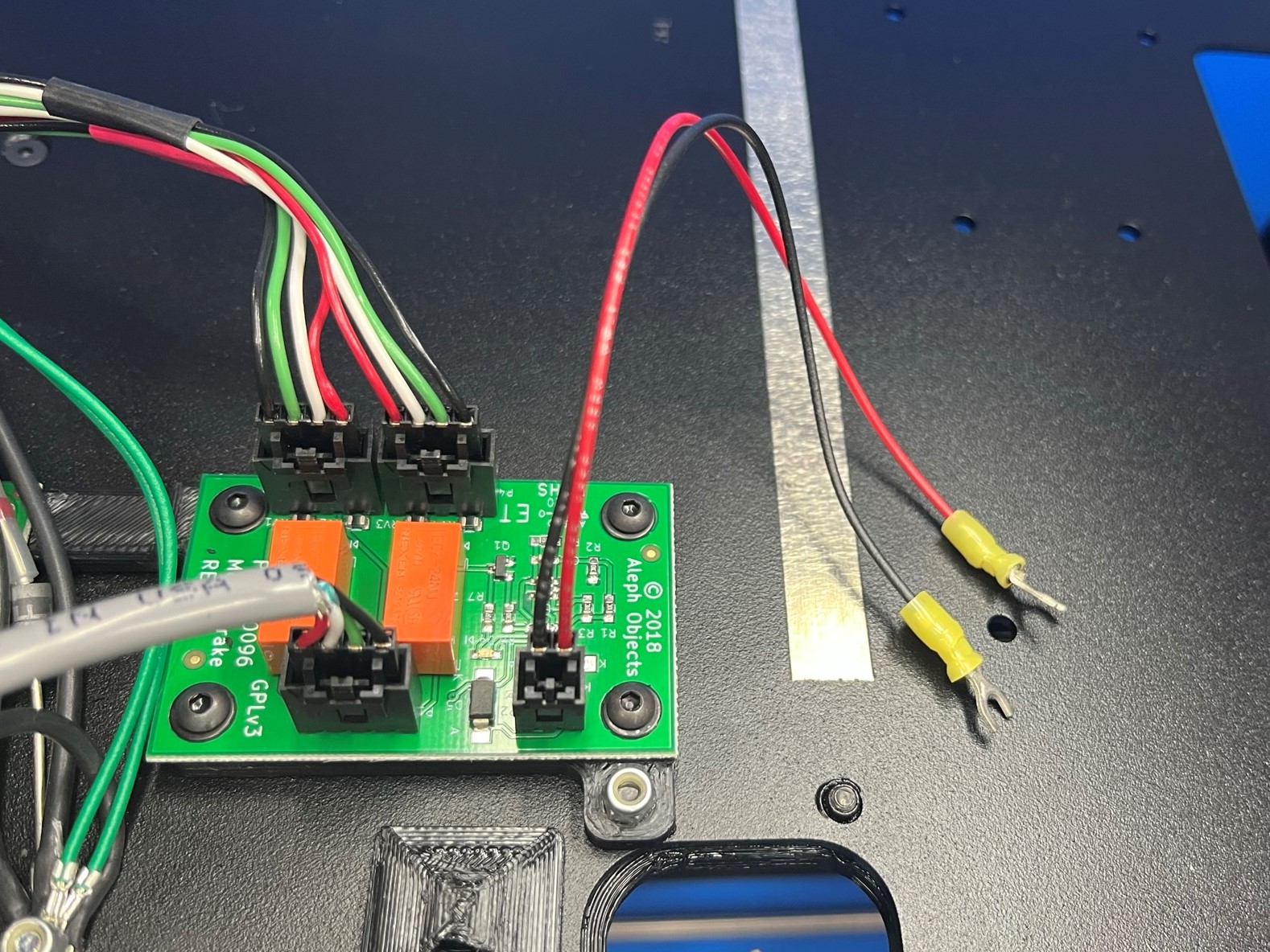
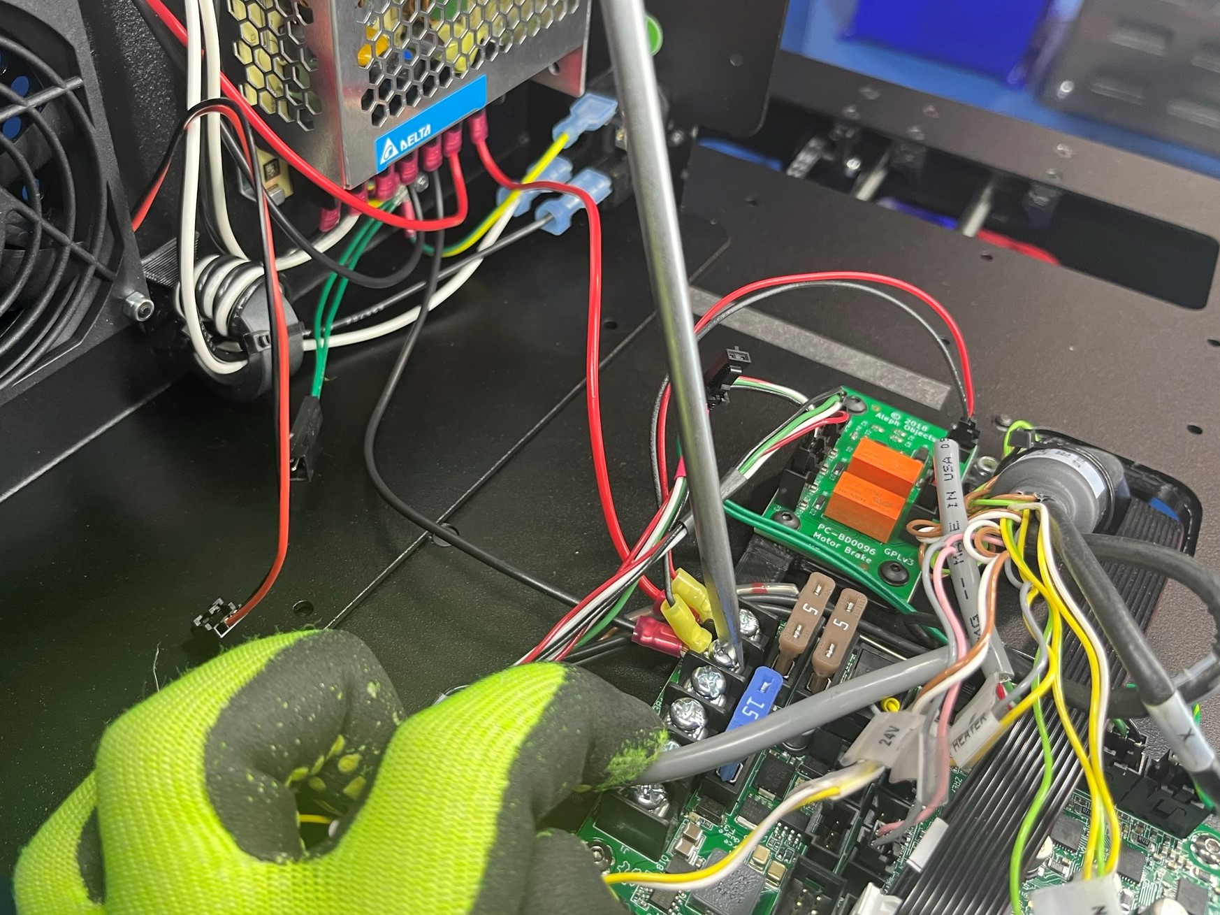
4. Locate the two wire harness that have red and black heatshrink, these are Z motors. Connect these to the left two connections on the Z brake board as pictured.
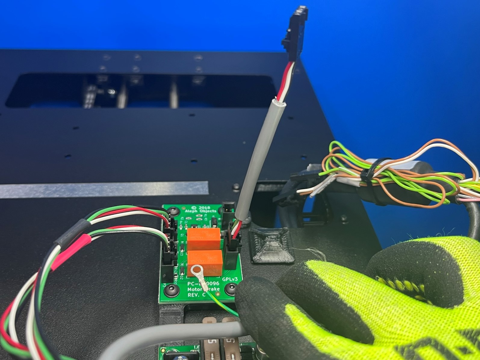
5. Connect the Z brake motor harness [AS-CB0070] to the port on the right side of the Z brake board. Then connect the other end of the Z brake motor harness to the retro board as pictured.


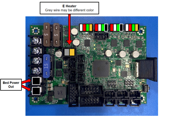
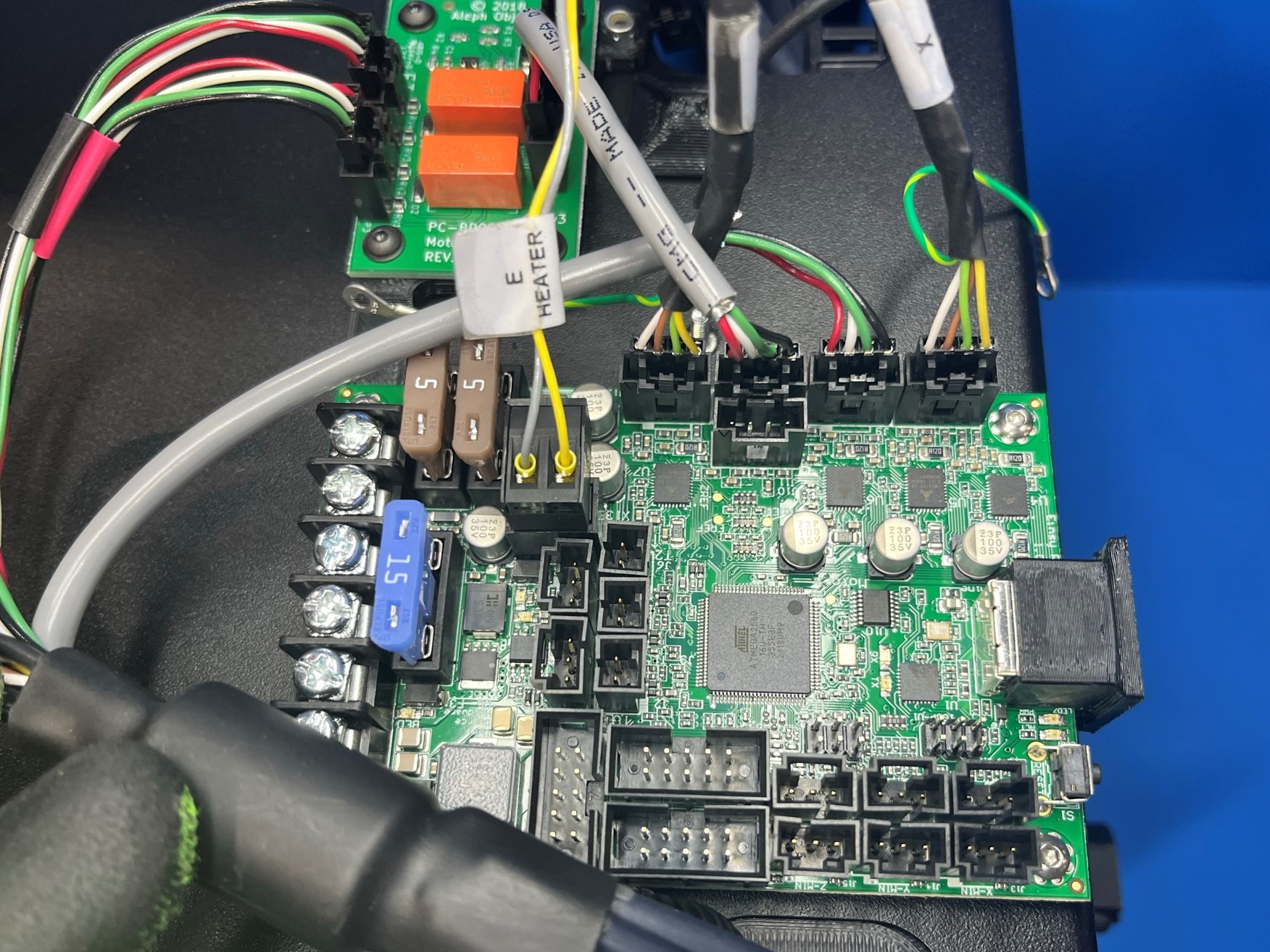
Locate the E heater terminal block connector and connect it to the board.
Then take the two short black wires that have fork connectors and slide them under the first two screw terminals. Then tighten the screws.

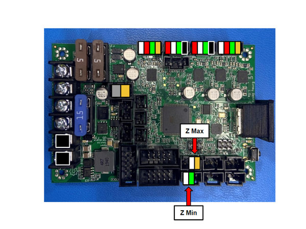
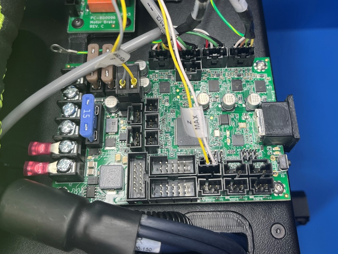
Find the wire harness that is labeled "Z Max" and connect it to the retro board.
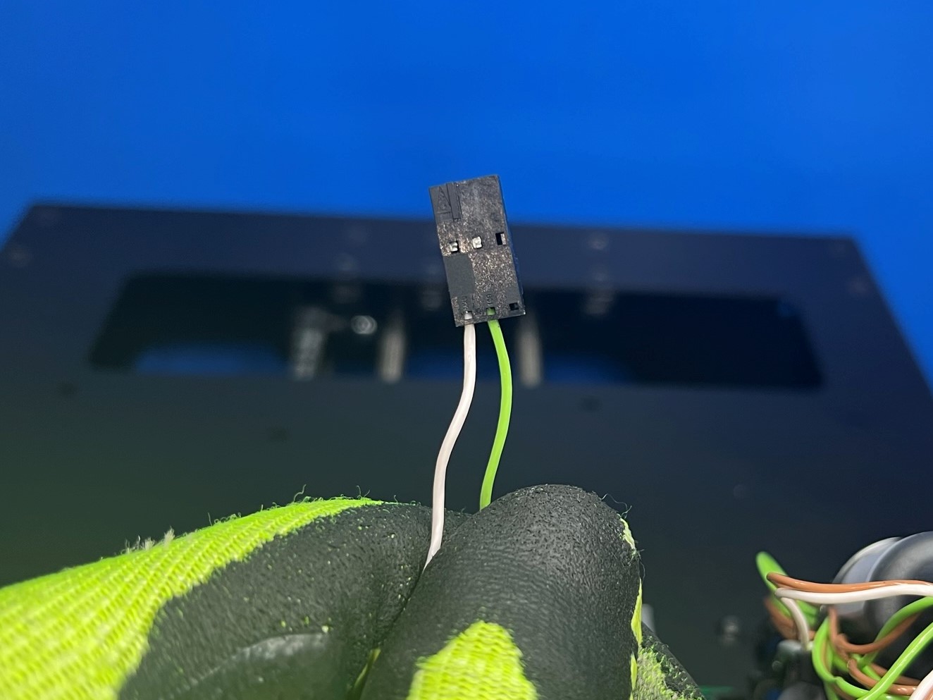
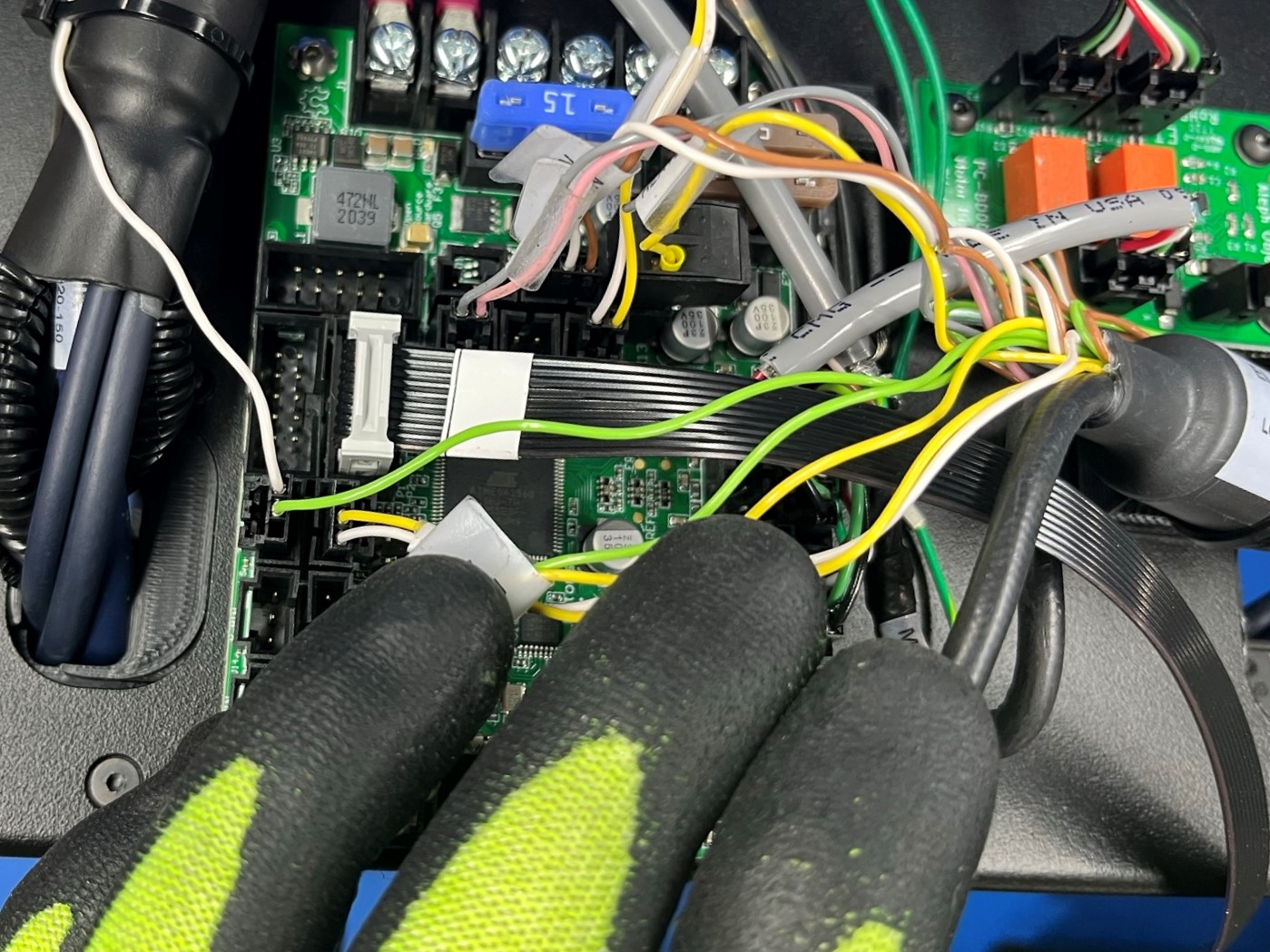
Within the top group of harnesses find the single green wire, then in the bottom cluster of harnesses find the white wire that has a connector on the end.
Slide the green wire into the middle slot of the connector that's connected to the white wire.
Make sure to have the locking tab on the green wire slide into the square hole on the backside of the connector

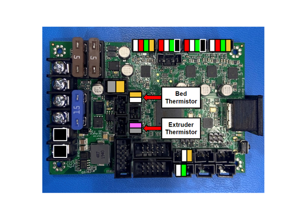
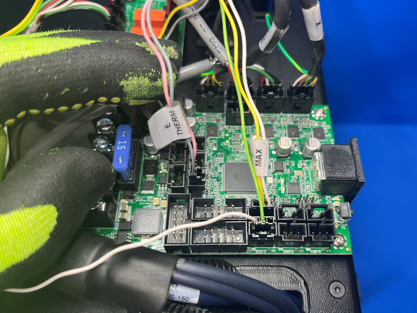
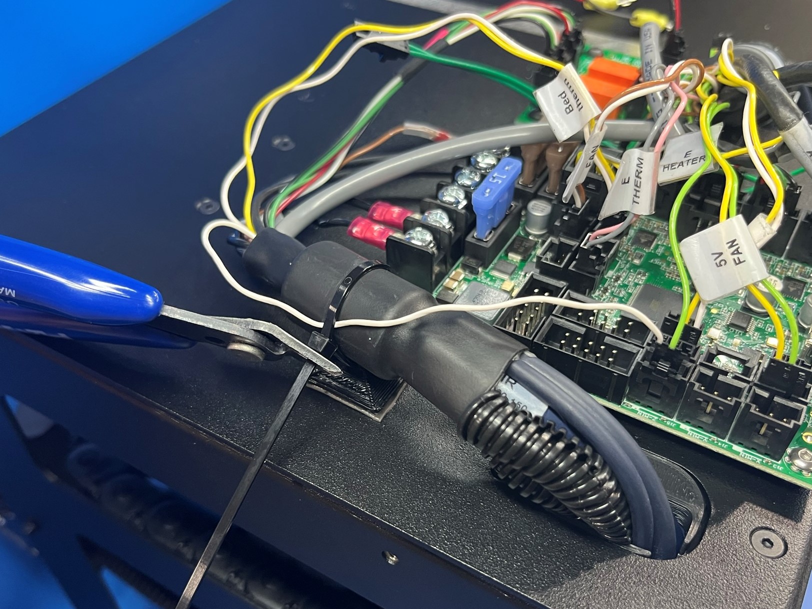
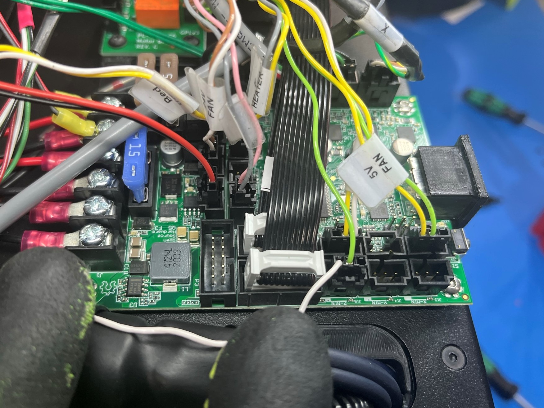
Locate the wire harness that's labeled “E Therm” and connect it to the board.
Then find the wire harness that's labeled “Bed Therm” and connect it to the board.
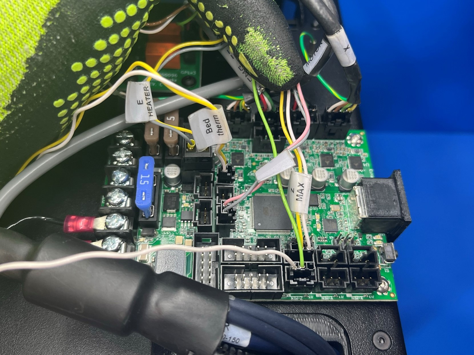
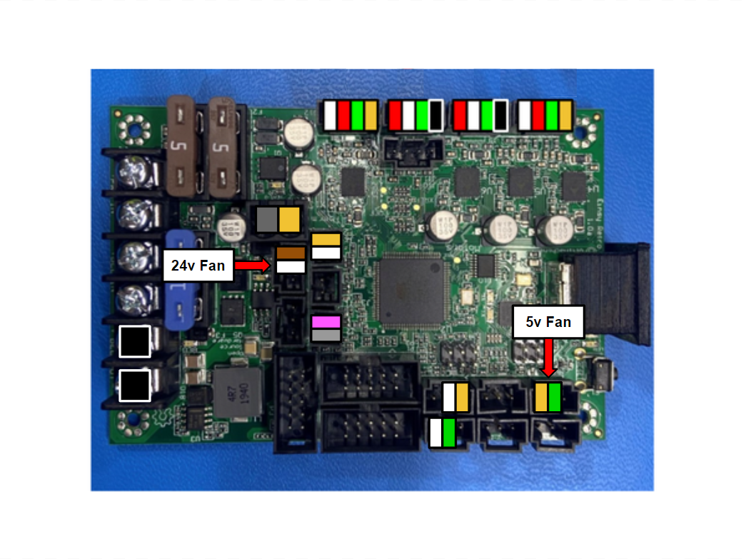
Find the wire harness that is labeled "24V Fan" and connect it to the retro board.
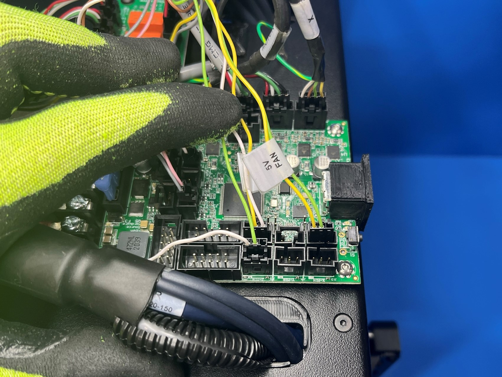
Now look for the wire harness that is labeled "5V Fan" and connect it to the retro board.

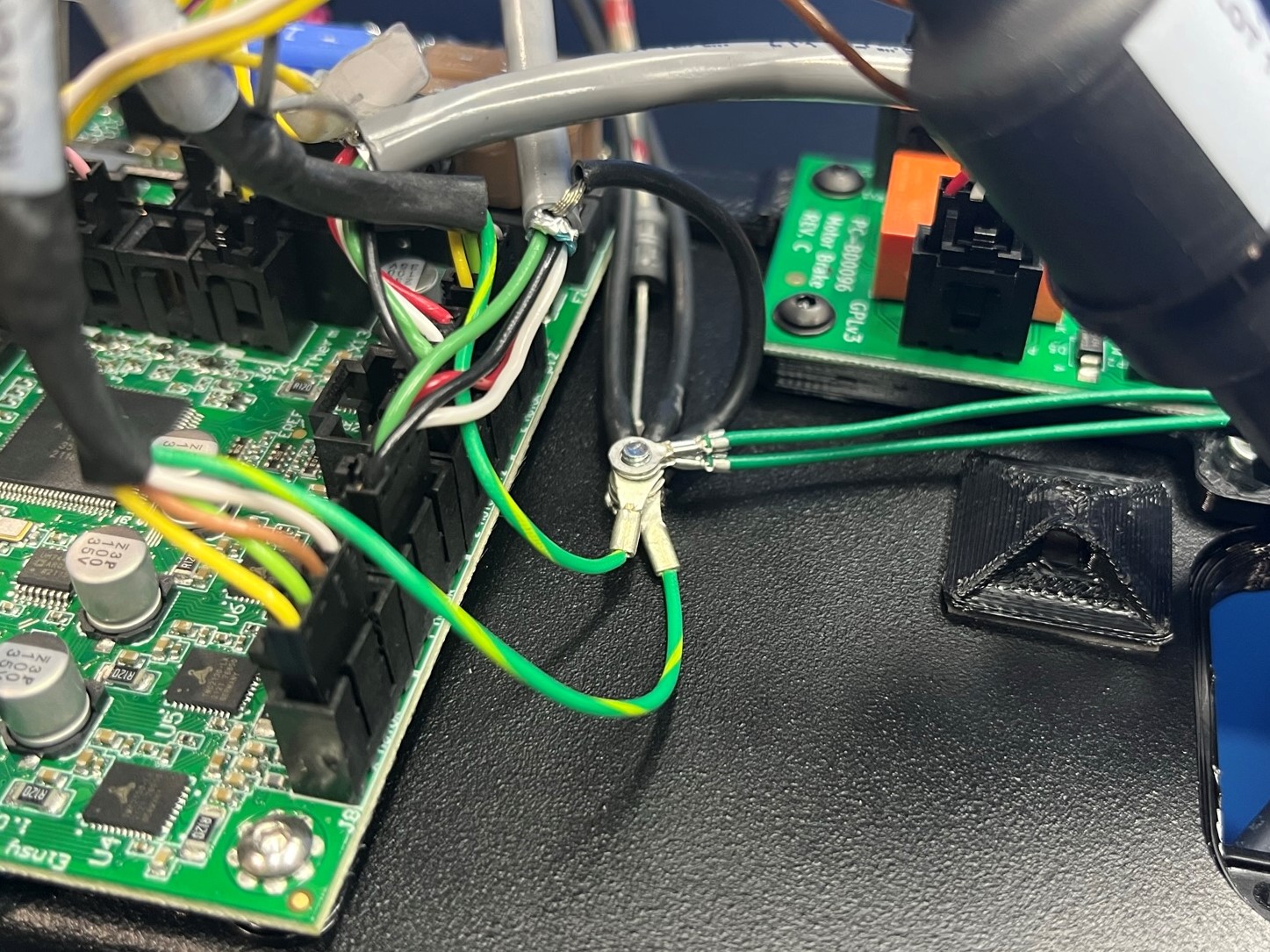
First put an M3 lock washer [HD-WA0035] onto the ground post that's next to the retro board.
There will be a total of 8 ring connectors that will be placed around this ground post.
The first wire is the single wire with bare wire showing at the end. It's apart of the bottom cluster of harnesses.
Now take the X motor, Y motor, and E motor ground wires and place it around the ground post.
Then look for two black wires within the bottom cluster of harnesses that have ring connectors on the end. Once you find the two wires slide them around the ground post.
The last two wires are a part of the chassis ground extension harness [AS-CB0082], slide both of the ring connectors around the ground post.
Once all 8 connectors are placed around the ground post use a M3 locknut [HD-NT0001] to secure the wires to the frame plate.

Bend the lower ferrite (YZ Harness) so that its positioned over the universal cable tie holder and make sure the single white wire runs along the harness, then secure both with a cable tie [HD-MS0058].
Repeat the process for the upper ferrite (X/Extruder Harness) and secure with a cable tie.
If the universal cable tie holders come off the frame plate replace them and leave the cable tie a little loose to reduce the tension.
With the end of the cable that has the wire facing the keyed side of the connector, connect LCD 2 [AS-CB0084] to the retro board.
With the end of the cable that has the wire facing the keyed side of the connector, connect LCD 1 [AS-CB0083] to the retro board.
Make sure both LCD harnesses run under the 5V fan, Z max, Z min, and the X motor. This will prevent the LCD harnesses from unplugging.
Route the two harnesses through the upper strain relief of the left plate, above the blue wires.


Connect the Z brake power harness [AS-CB0069] to the Z brake board.
Place the electronics case assembly next to the retro board.
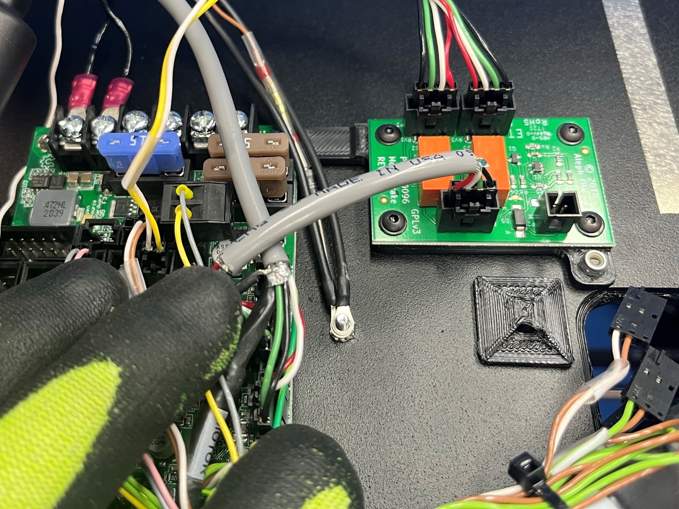
Connect the right-most red wire from the power supply to the top left terminal on the board by loosening the terminal screw with a Phillips screwdriver and inserting the fork terminal underneath as pictured. Before tightening this terminal, insert the fork terminal of the Z-Brake power harness' red wire Tighten securely.
Repeat for the right-most black wire from the power supply to the second terminal from the top, on the left side of the board by loosening the terminal screw with a Phillips screwdriver and inserting the fork terminal underneath. Before tightening this terminal, insert the fork terminal of the Z-Brake power harness' black wire. Tighten securely.
Then slide the other red wire in the next screw terminal followed by the black wire in last screw terminal. Once both wire are under the screw tighten both screws.
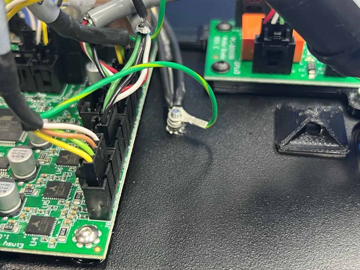
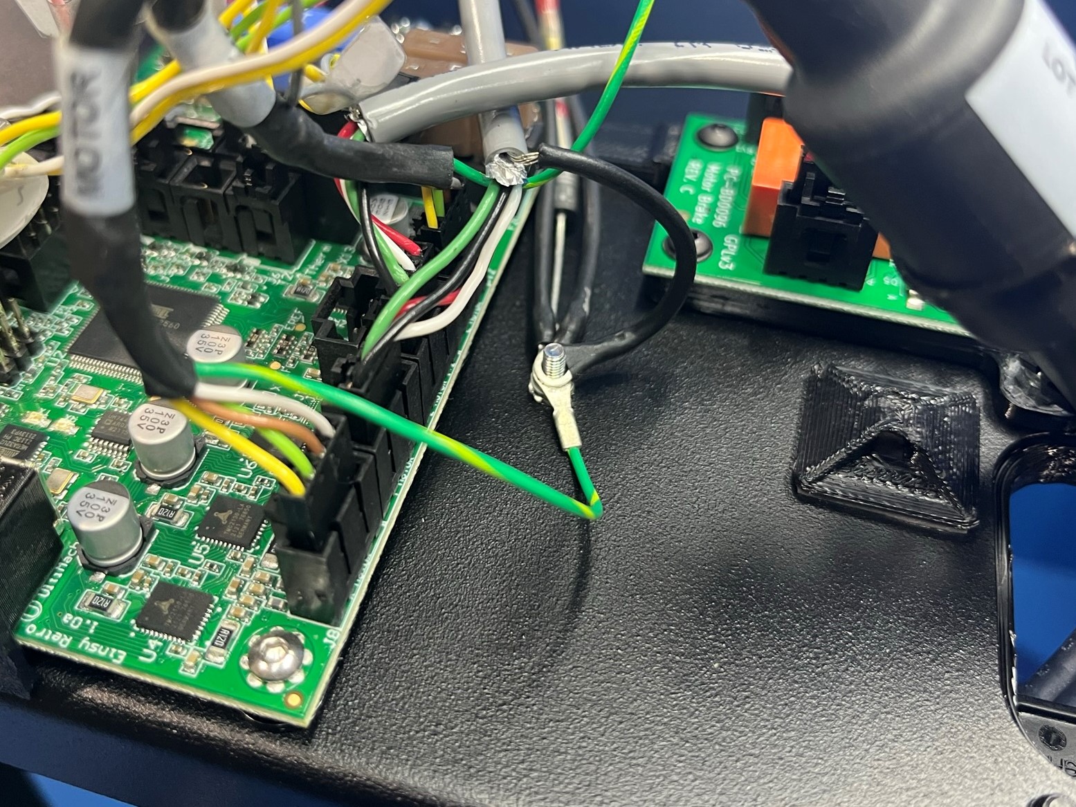
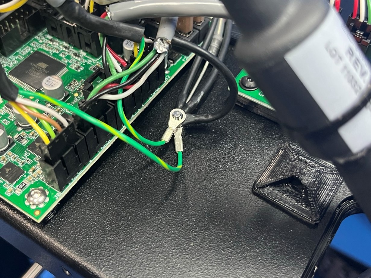
Connect the Chassis to Ground Extension cable to the Earth Ground Extension cable.
Connect the Case fan harness to the retro board.


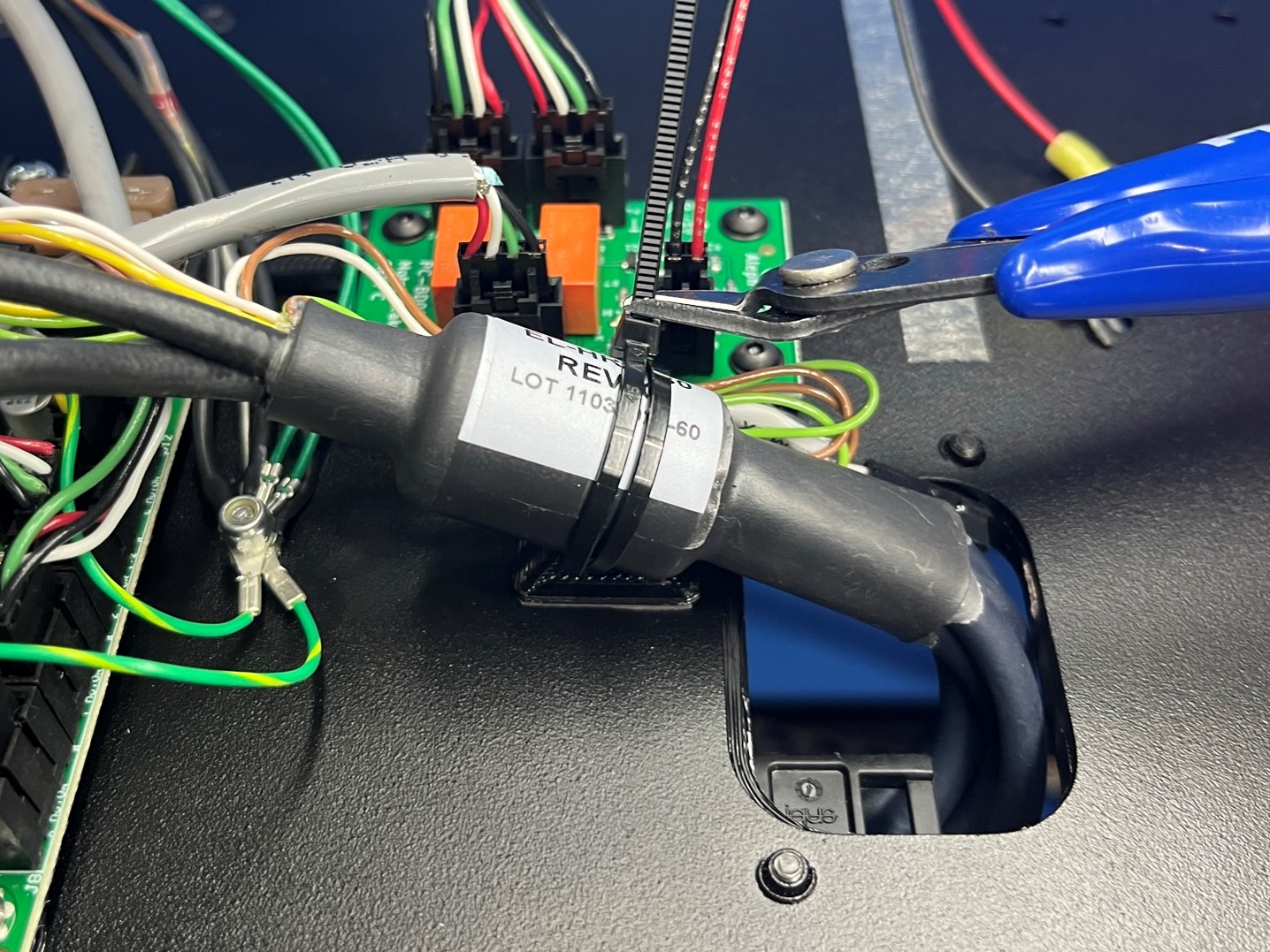
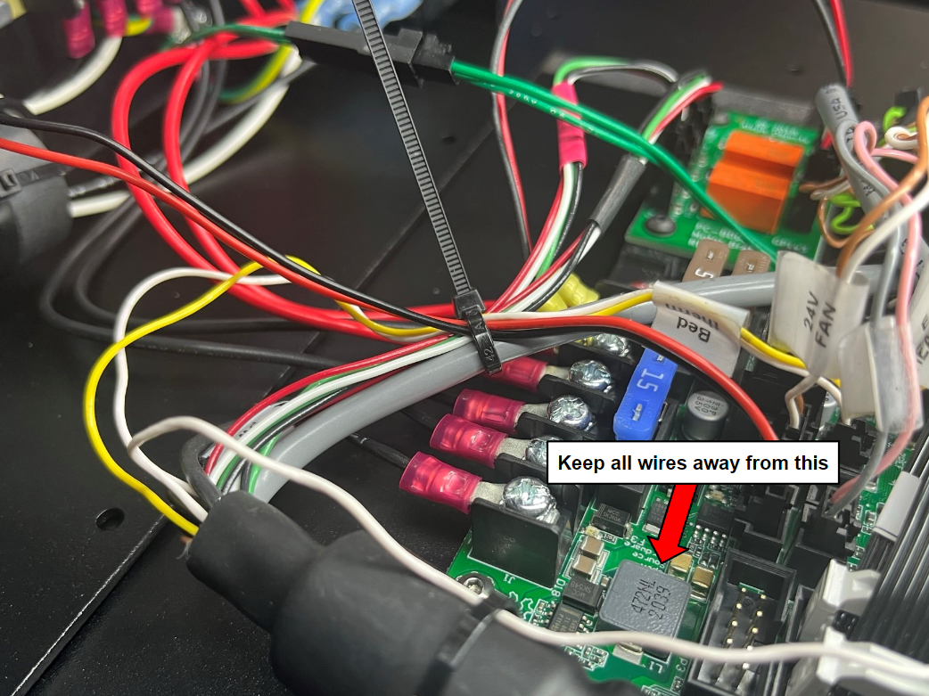
Once the electronics case is connected to the retro board, use a cable tie to secure the lower harness wires to the electronics case wires.
Make sure there is no wires near the grey box as shown.
Before installing the electronics case, carefully inspect all connections according to the harness diagrams.
Make sure all the harnesses and wire clusters are secured to the left frame plate, check by the case fan that there is no labels or cable ties sticking out.
Carefully place the electronics case over all the wires and electronics, then attach it to the left frame plate using 6x M3x6 FHCS [HD-BT0128] to fasten the case to the left plate front and left plate back.
Now secure the bottom of case using 2x M3x8 BHCS [HD-BT0137] with M3 washers [HD-WA0038]

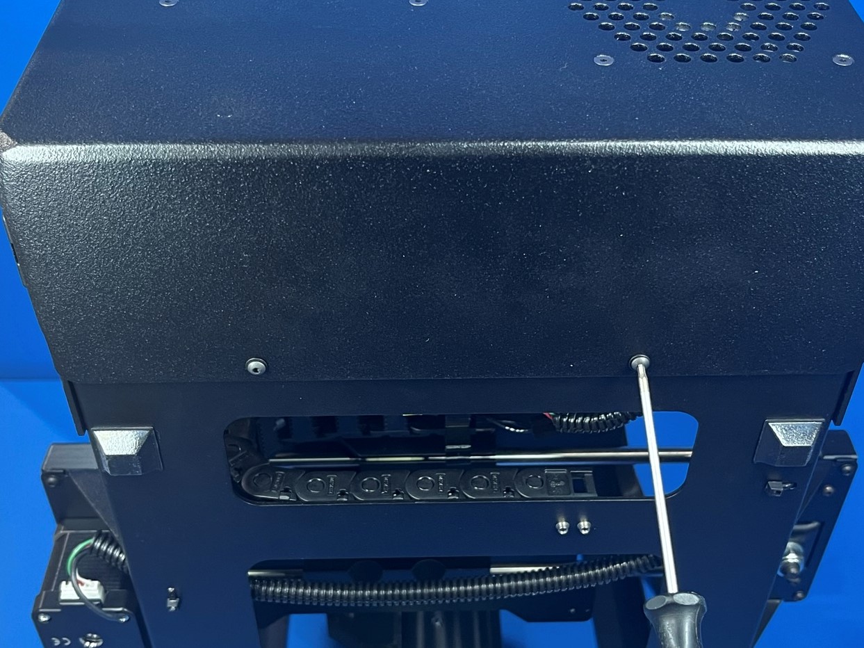
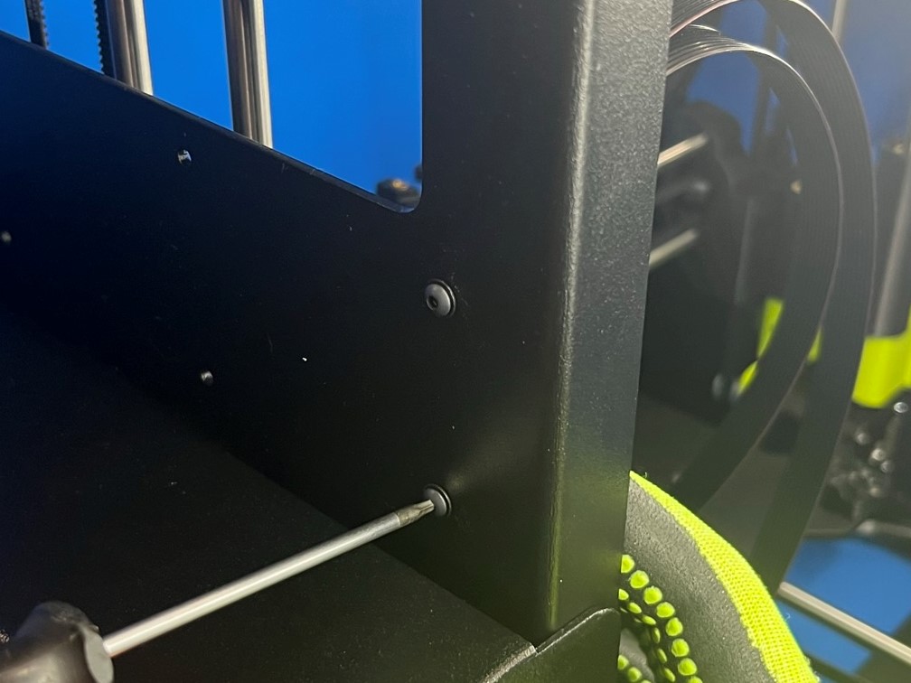
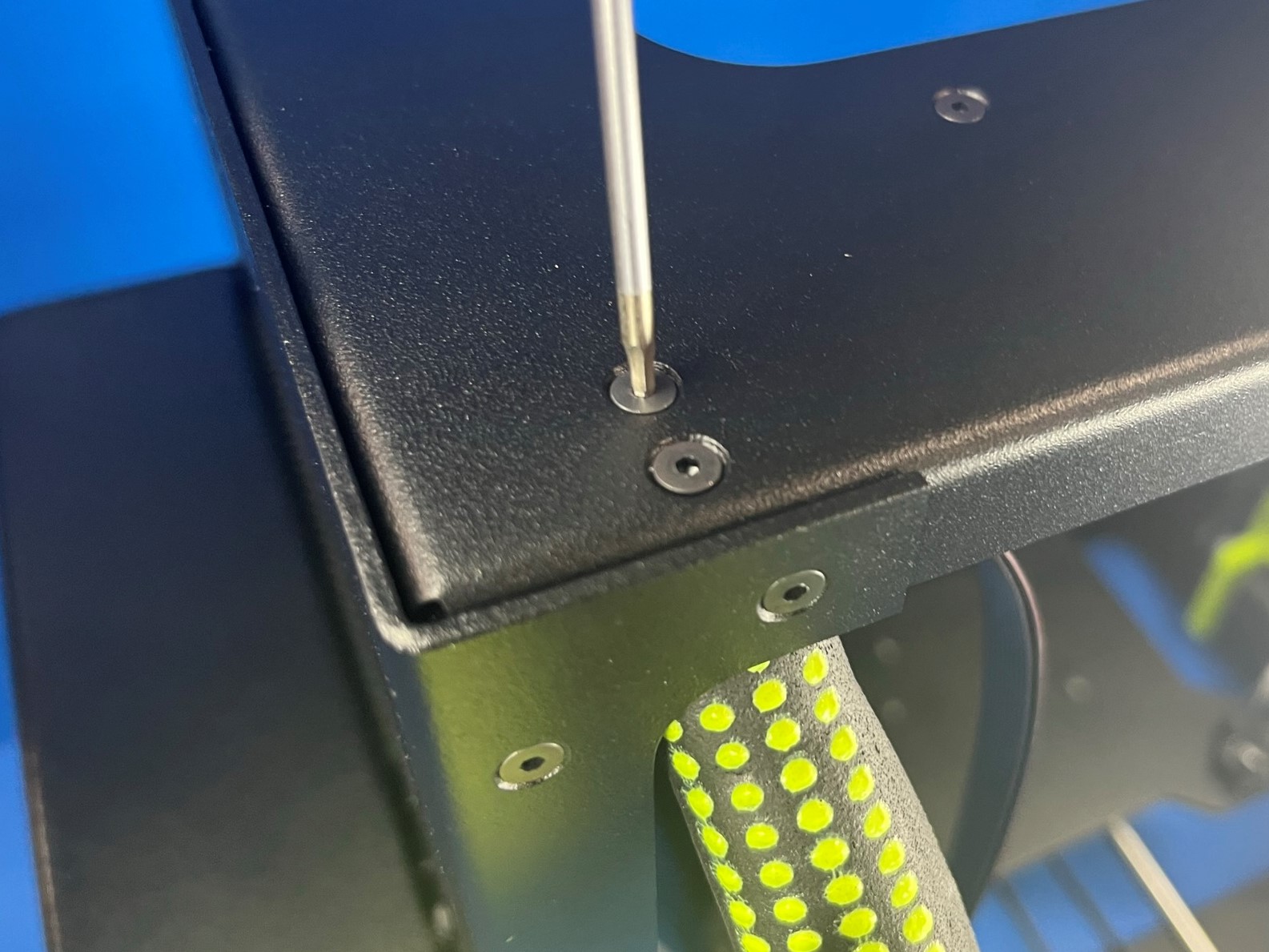
Thread harnesses through the side cable bracket, and hold in place above the frame hole. Adjust orientation so that holes align with frame.
Secure the Side Cable Bracket [PP-GP0327] as pictured using two M3x8 BHCS [HD-BT0137] with washers [HD-WA0038]
Torque to 5in*lbs
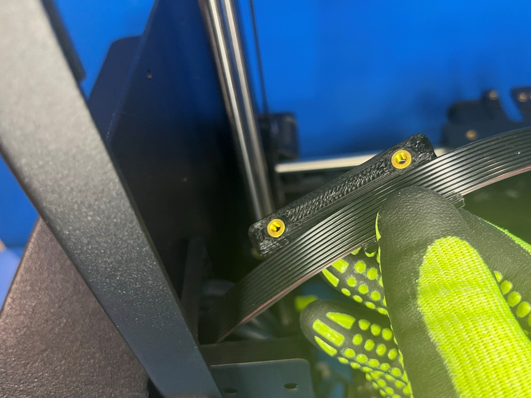
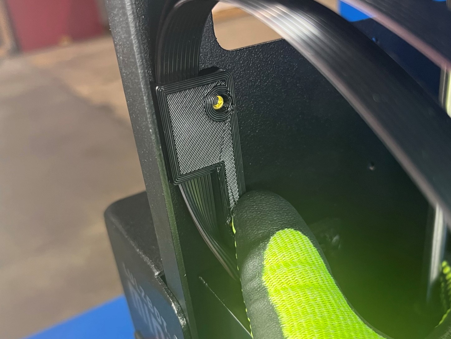
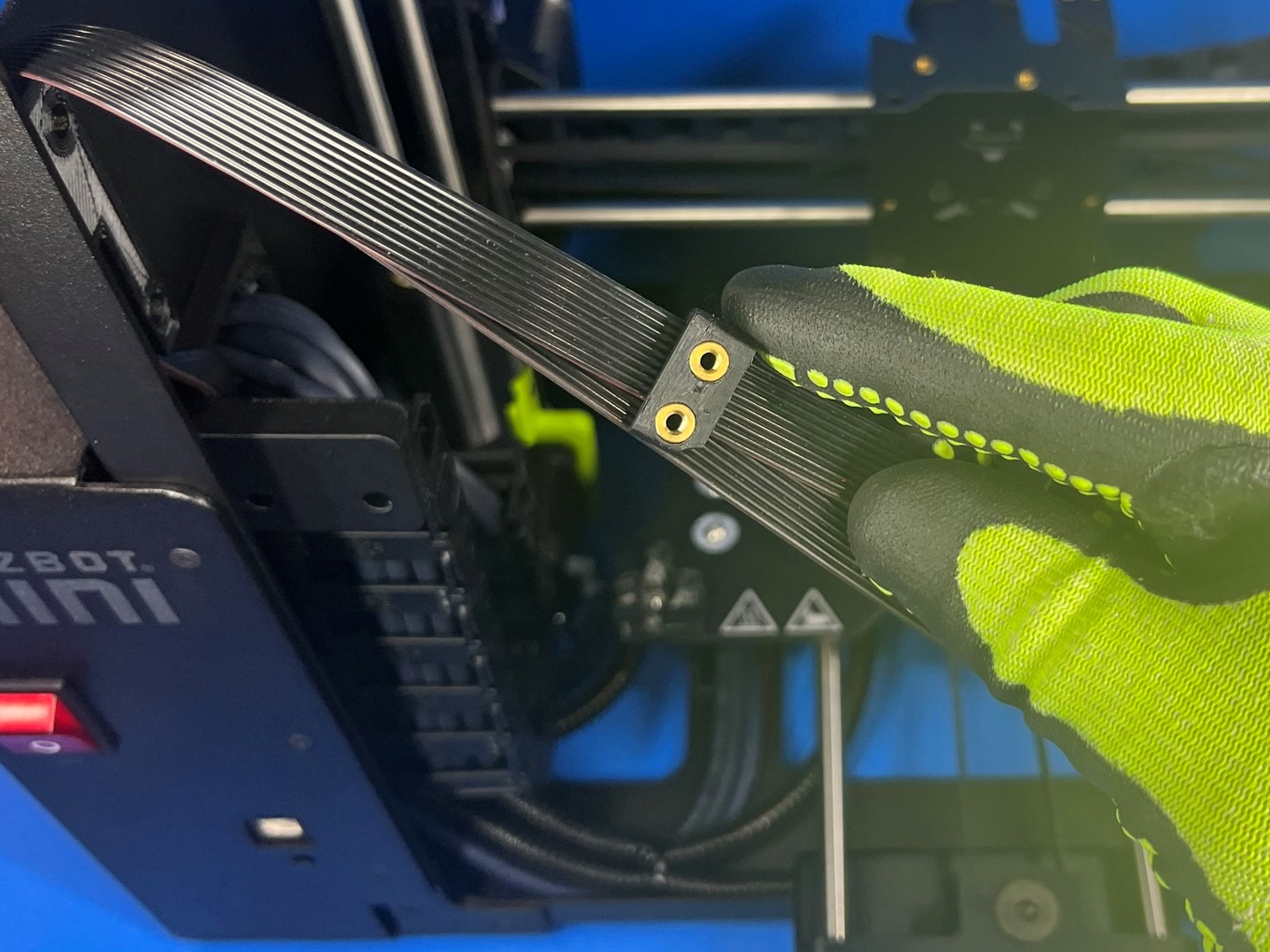
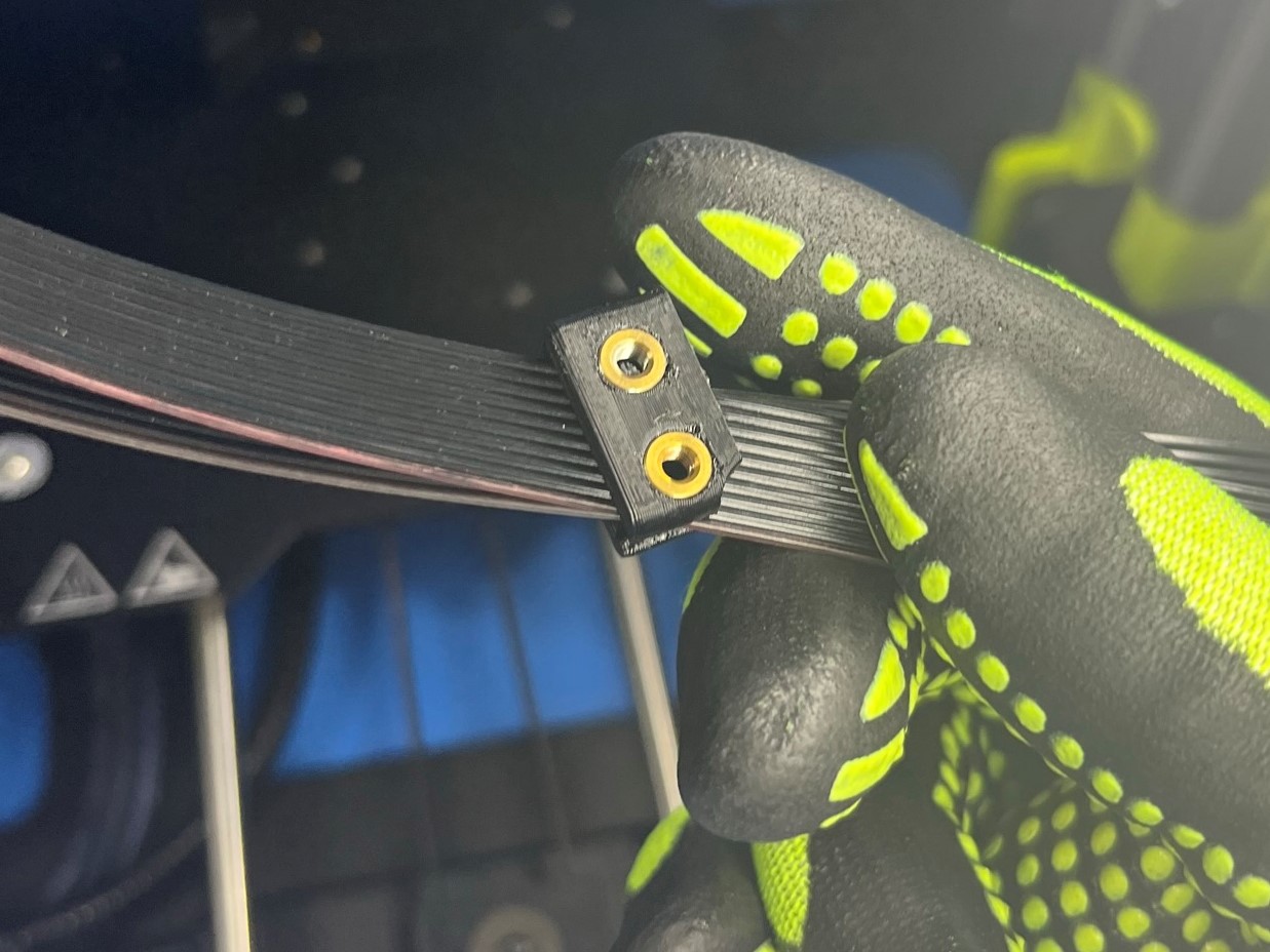
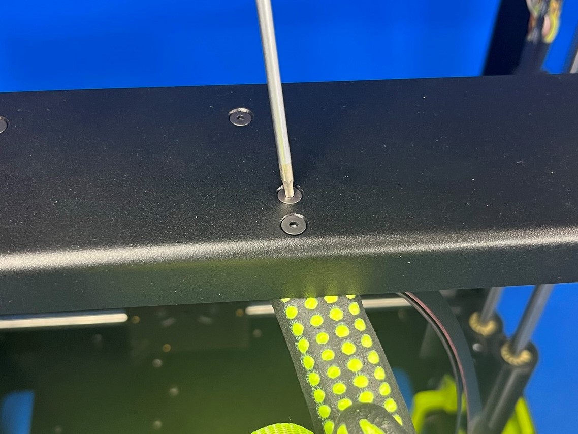
Slide a Top Cable Bracket [PP-GP0326] over both LCD Harnesses and line up with holes in top plate, starting with the two on the left.
Secure using two M3x6 FHCS [HD-BT0128]
Torque to 3in*lbs
Slide another Top Cable Bracket [PP-GP0326] over both LCD Harnesses and line up with holes in top plate towards the right.
Secure using two M3x6 FHCS [HD-BT0128]
Torque to 3in*lbs
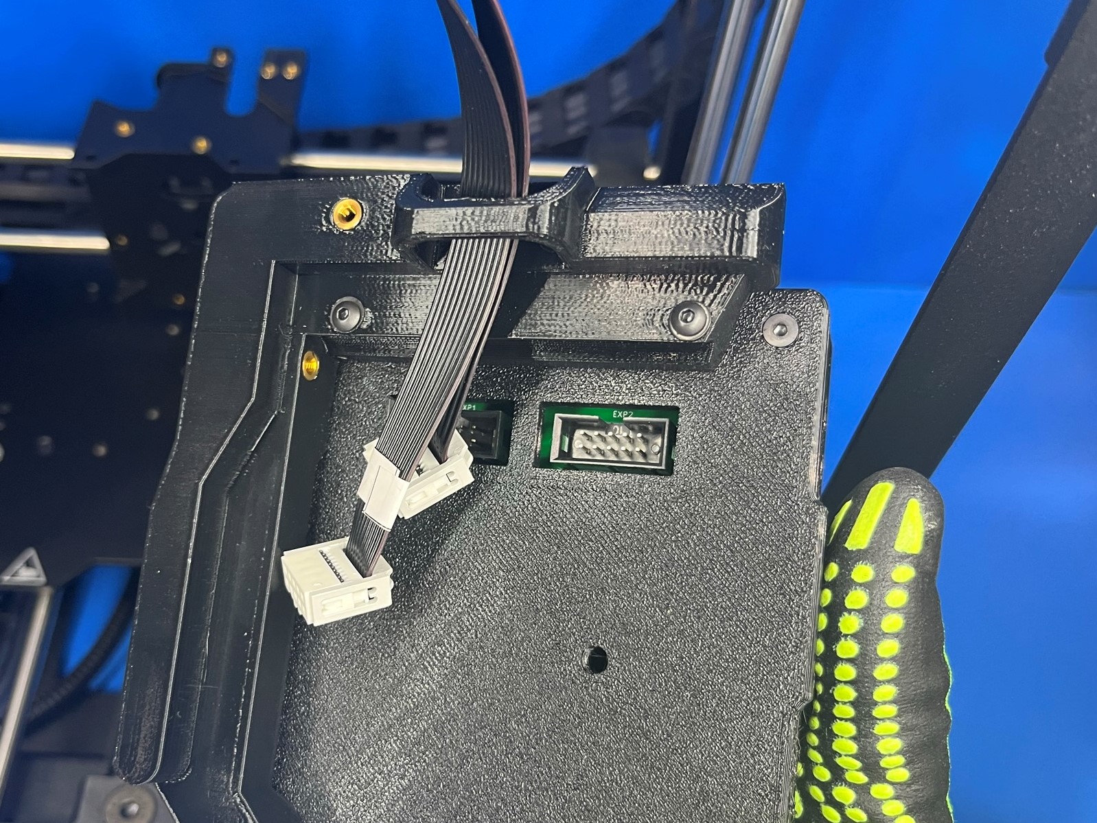
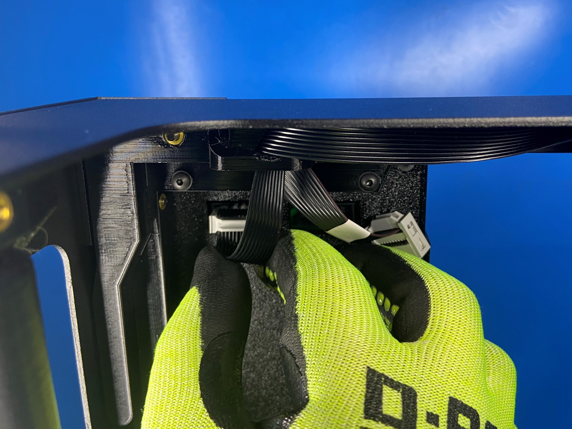
Thread the harnesses down through clip on the back of the LCD Assembly [AS-EL0002] as shown in image.
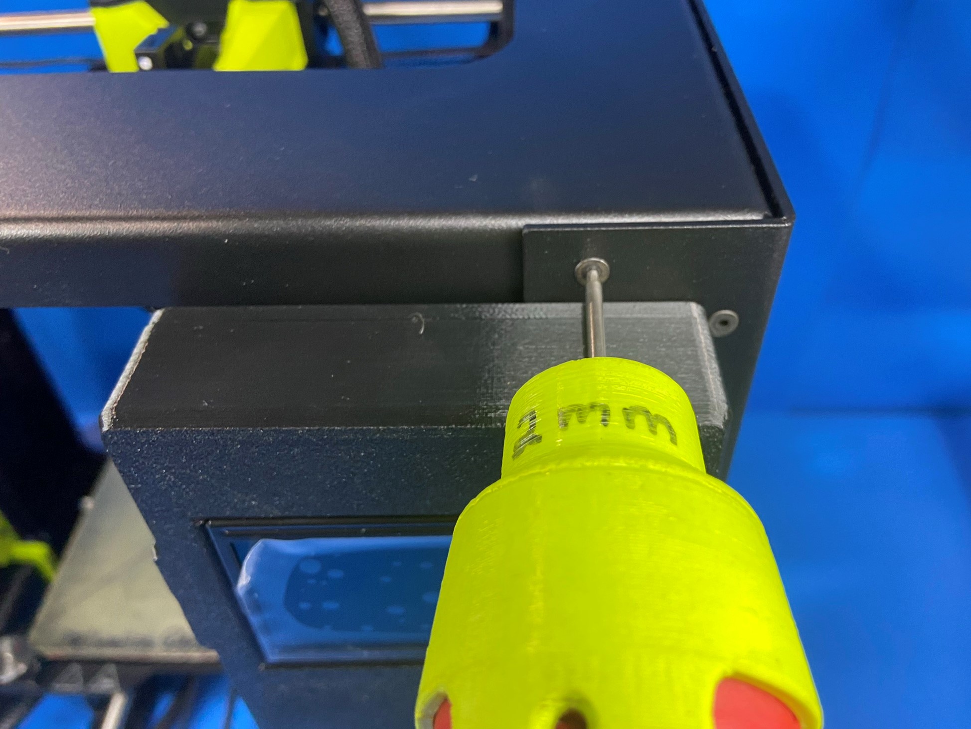
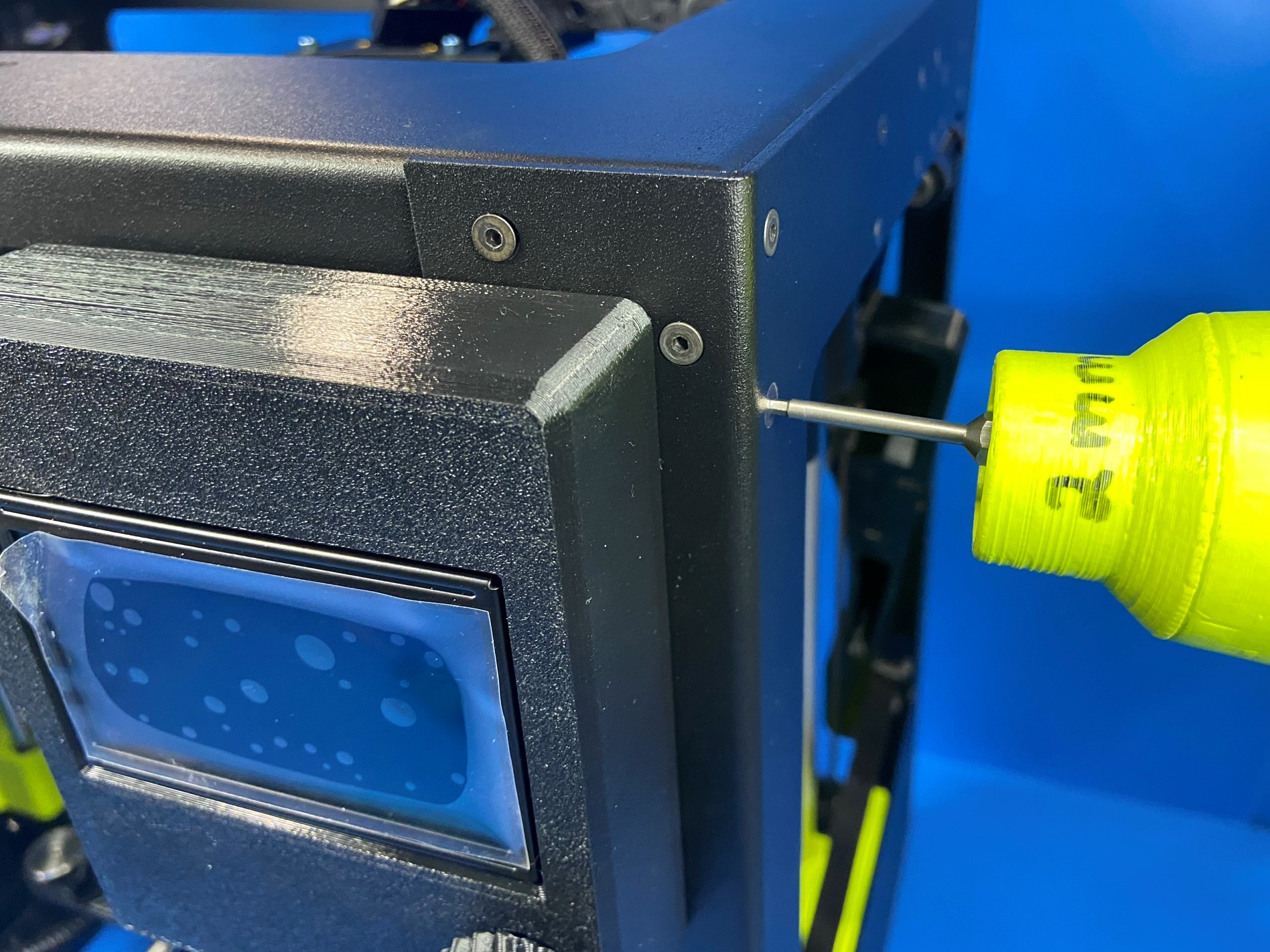
Using two M3x25 FHCS [HD-BT0206], secure the LCD Assembly [AS-EL0002] to the front top right corner of the machine.
The screws go in the open holes on that corner of the frame.
NOTE: Be cautious when securing the LCD Assembly that you are not pinching your LCD cables underneath the mount.
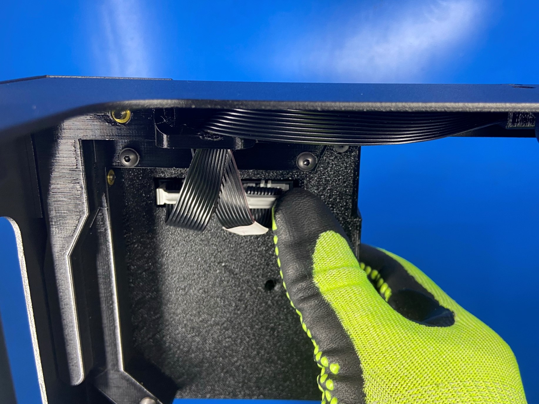
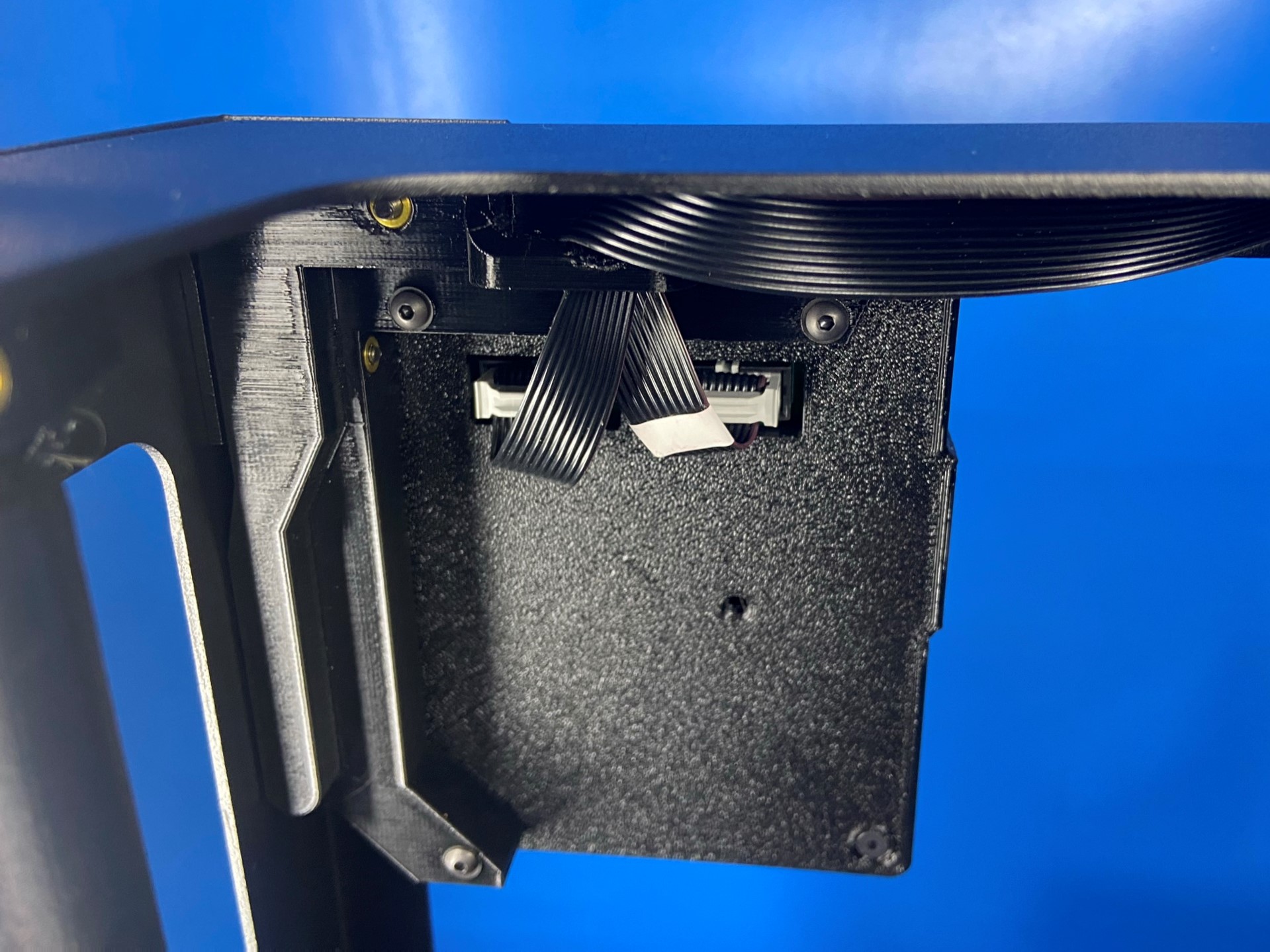
Connect LCD Harness 1 [AS-CB0083] (without white label) to the left port on the back of the LCD Controller as pictured.
Connect LCD Harness 2 [AS-CB0084] (with white label) to the right port on the back of the LCD Controller as pictured.
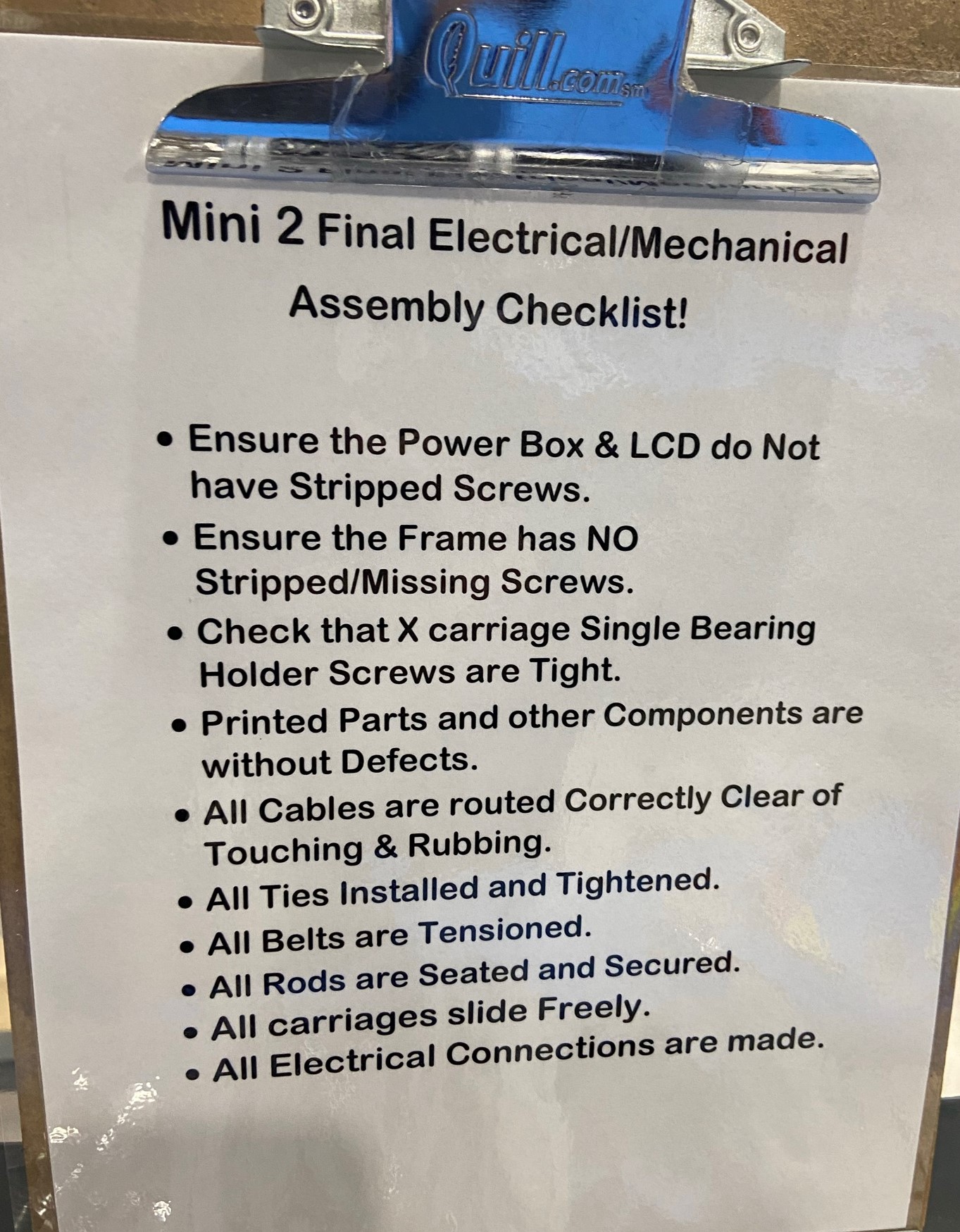
Look over the Mini 2 Final Electrical/Mechanical Assembly Checklist and make sure every step was followed.