Open HardwareAssembly Instructions
Guides for installation and assembly of the LulzBot line of products made by FAME 3D LLC.
Guides for installation and assembly of the LulzBot line of products made by FAME 3D LLC.
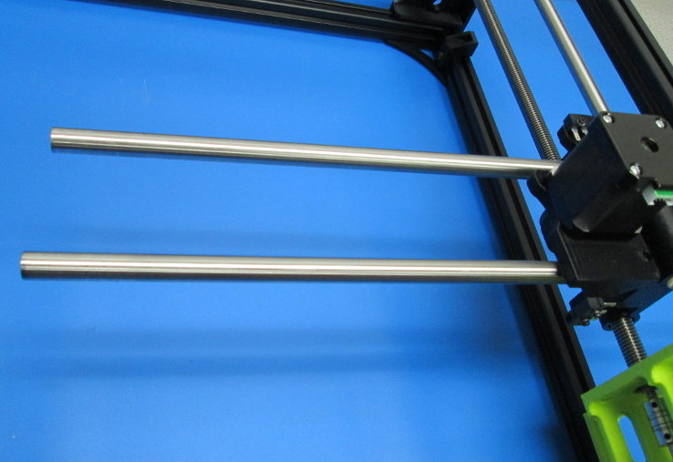
2x- 12mm OD, 515mm long smooth rod
2x- M3 set screws
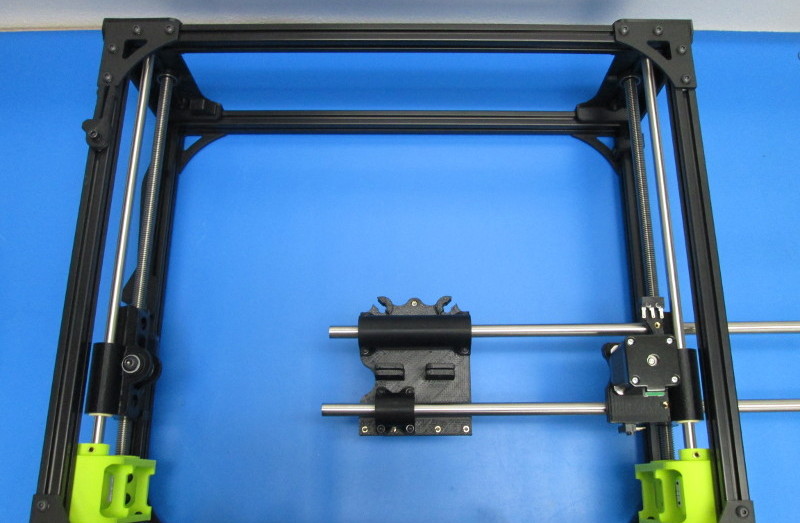
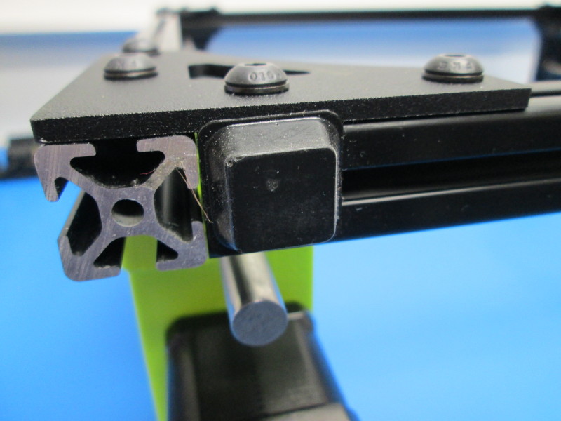
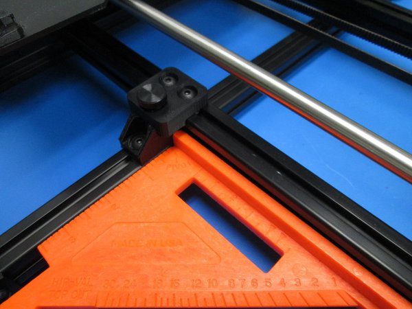
Carefully take the frame to a flat surface and use a square to ensure the frame is perpendicular to the flat surface.
Slide two 12mmX 515mm smooth rods from the X End Left halfway into the frame assembly through the X End Left assembly.
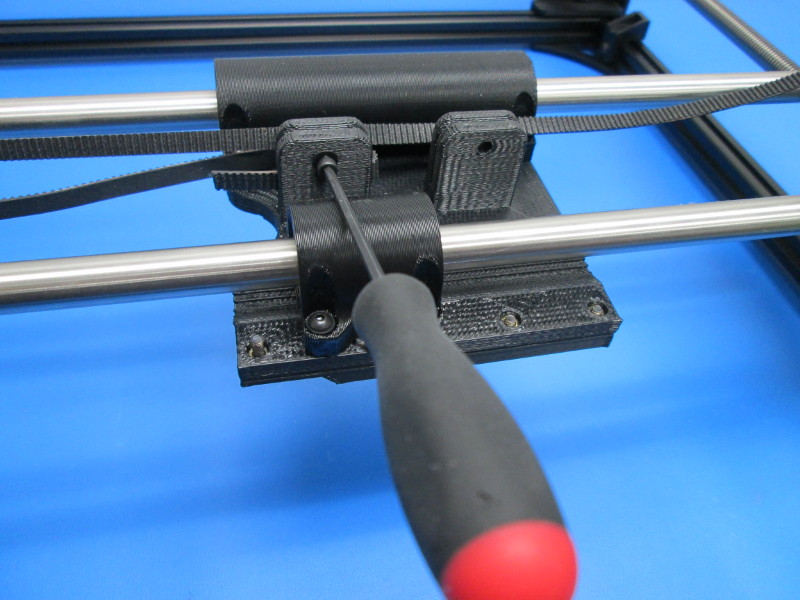
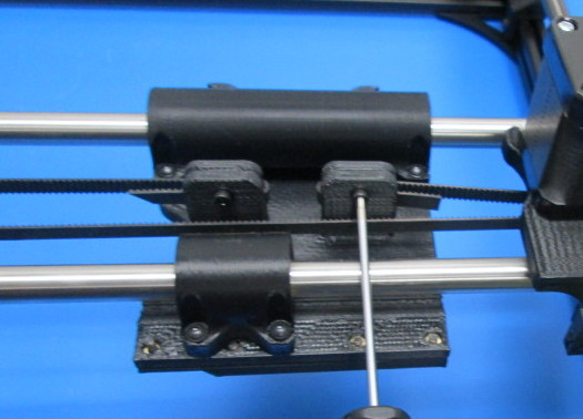
Slide the X carriage assembly onto the guide rails, and slide the guide rods into the motor side carriage.
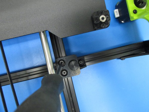
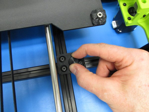
Make sure to flush up the smooth rods on the X End Right side.
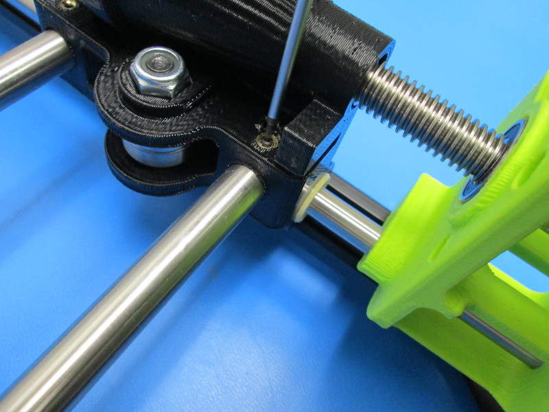
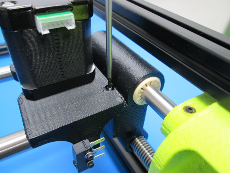
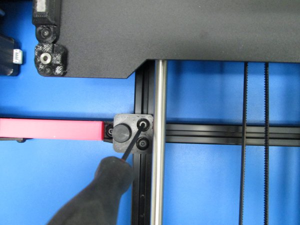
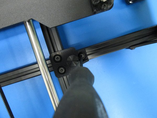
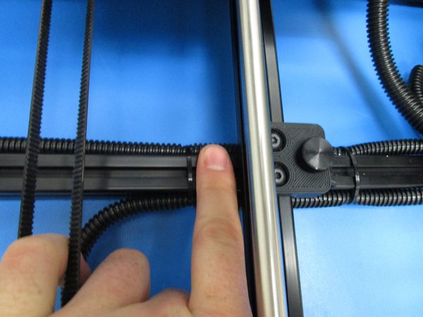
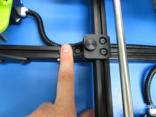
Using two (2) M3 set screw (one each on the Right End and Left End) tighten the guide rod set screws on both the X End Left and Right to 3in-lbs.
1x- 6mm synchronous belt
2x- M3x12 SHCS
2x- M3 black washer
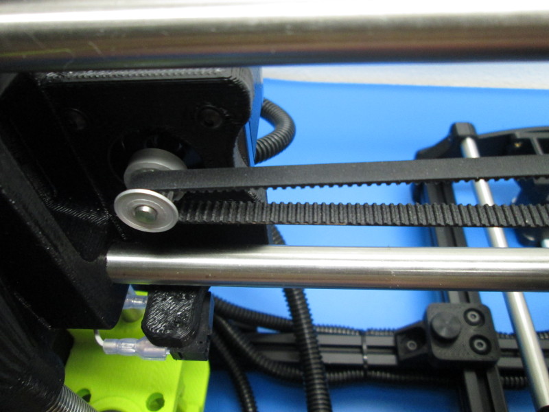
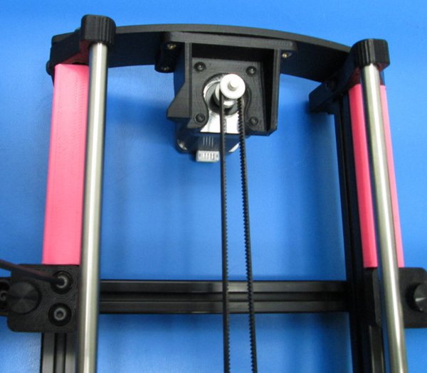
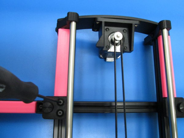
Snip one location on the drive belt to create an approximately 1m long non-continuous drive belt; Set one end of the drive belt with the smooth side oriented toward the single bearing holder into the belt clamp closest to the single bearing holder; secure the belt in the clamp with one (1) M3x12 SHCS and one (1) M3 black washer, tightened to hand tight
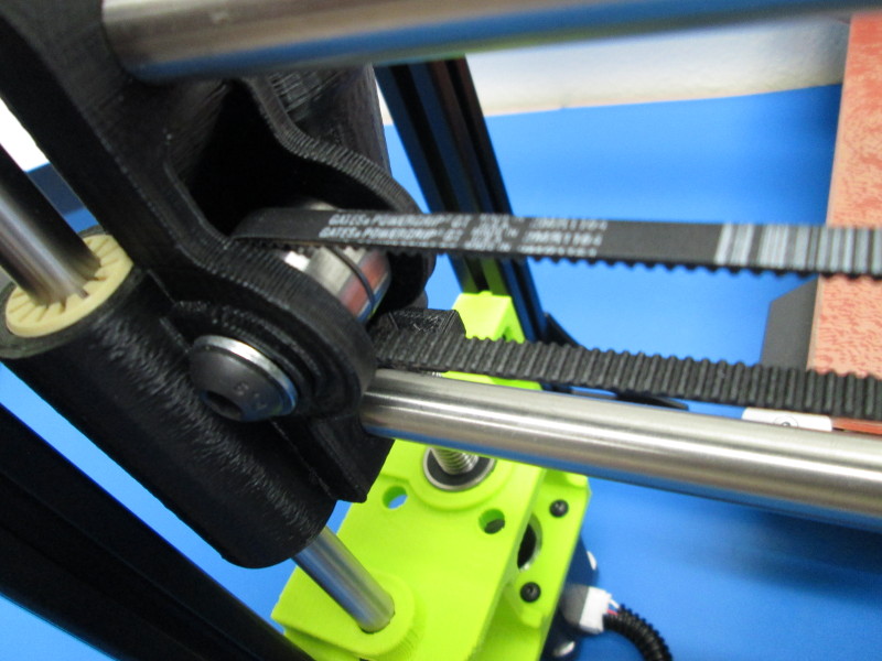
Without twisting the belt route the belt around the X axis pulley so the belt teeth engage the pulley teeth then around the Z axis idler
Set the remaining end of the drive belt into the second belt clamp; align the belt with the step feature in the clamp; Tension the belt to approximately 23 to 27 Newtons; secure the belt in the clamp with one (1) M3x12 SHCS and one (1) M3 black washer, tightened to hand tight; Trim excess belt back to no more than 10mm from the belt clamps.
4x- 3/4” wide, 1/4” high rubber bumper
2x- Coupling GSASL16-5-5-NAB with 4x set screws
8x- M3x10 BHCS
8x- M3 Black washer
2x- Moon's Nema 17 Stepper Motors
Loctite 220
Clean all oils and debris that might be present from the two bottom extrusions; install one (1) rubber foot pad at the end of each bottom extrusion by pressing and holding the foot pad in place (with adhesive protector removed) against the extrusion for at least 7 seconds.
Stand the assembly up so that it is standing on the rubber feet.
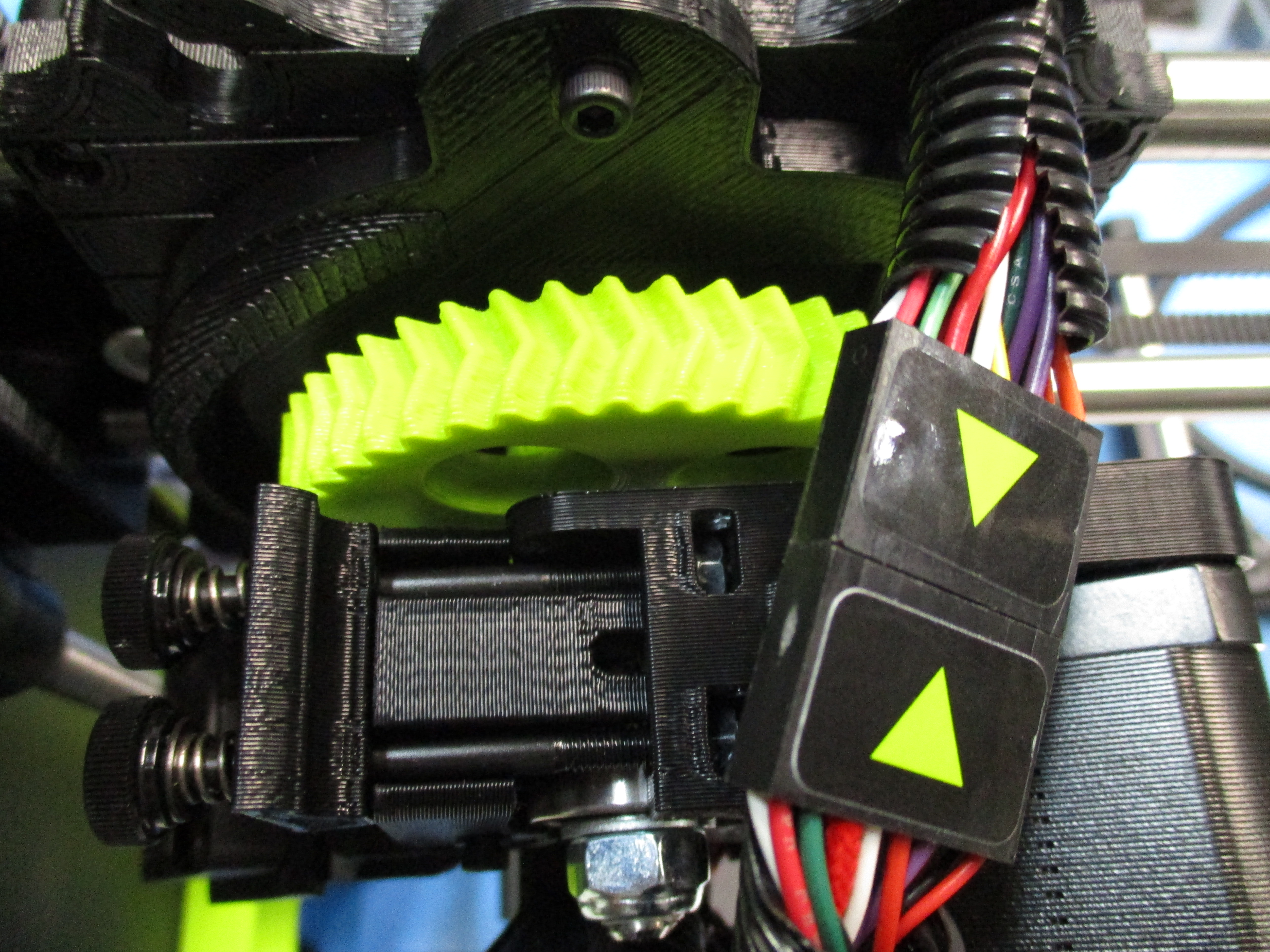
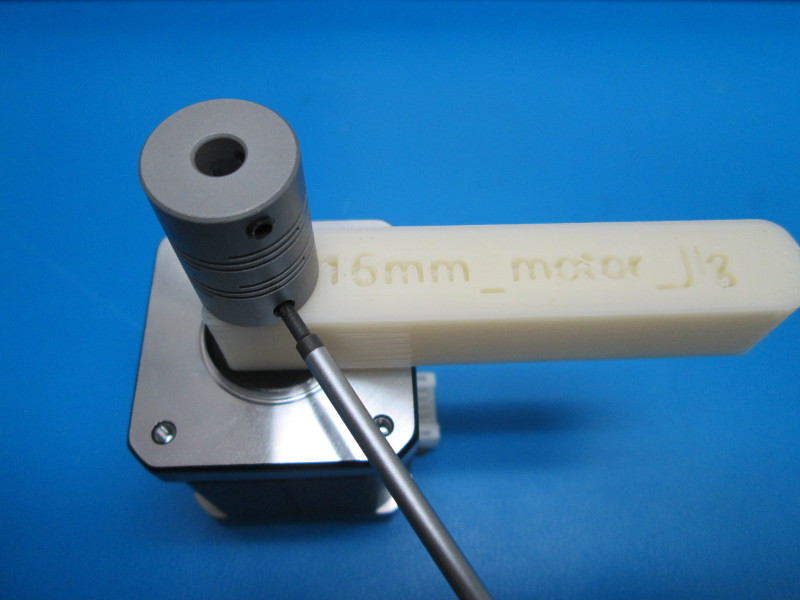
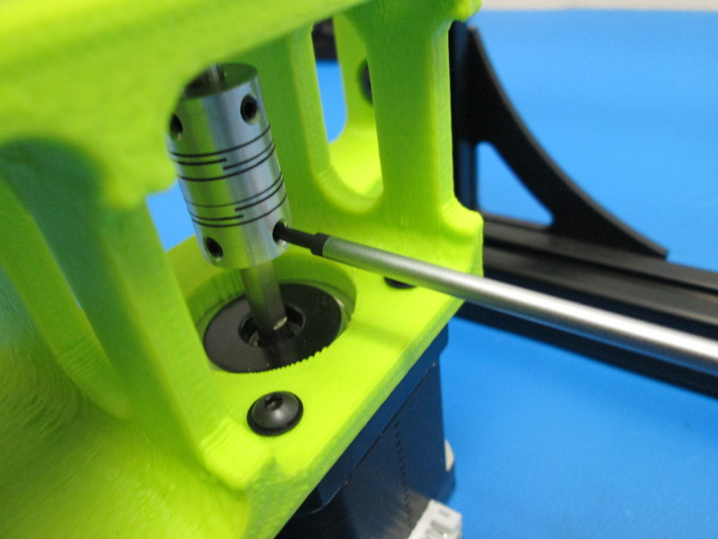
Install a coupler onto the shaft of a motor; align one of the two lower set screws with the flat section of the motor shaft; set the height of the coupler to 16mm tighten each of the two (2) lower set screws to finger tight. Repeat this for a second motor- together they are the Z Left and Z Right motors
Install the motor/ coupling assembly onto the end of the drive rods (left and right sides) making sure to align the motors so the white motor connectors are oriented toward each other.
Secure each motor to its mount with four (4) M3x8 BHCS and four (4) M3 Black washers, tighten to hand tight
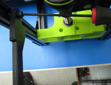
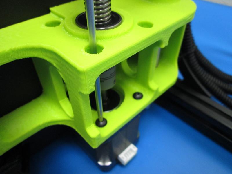
Secure the coupler to the drive rod shaft; align one of the two lower set screws with the flat section of the drive rod shaft; tighten each of the two (2) upper set screws to finger tight. Repeat this for a second motor/ drive shaft connection
Apply Loctite 220 to each of the coupler set screws, ensure no residue leaks onto the coupler, clean away any excess material immediately with a clean dry cloth.
1 Gather Parts and Tools
Parts:
1x- TAZ 6 Frame Final Assembly (AS-PR0006)
1x- TAZ 6 Control box (AS-PR0004)
1x- Y axis assembly (AS-PR0021)
1x- TAZ 6 Extruder assembly (AS-TH0014)
1x- TAZ 6 Spool Arm with bearing assembly (AS-PR0012)
1x- Tippy Feed tube assembly (AS-PR0011)
1x- Feed tube spinner (PP-GP0219)
8x- M5x10 BHCS
8x- M5 Black washers
4x- Control box mounts
2x- M5 T-nut
Tools:
-Flush cutters
-4mm driver
-3mm ball end driver
-2.5mm ball end driver
-2mm driver
-Ruler
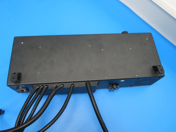
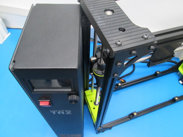
Install two (2) control box mounts to the rear side of the control box using one (1) M5X10 BHCS and one (1) M5 black washer per mount. Torque to 10in-lbs.
Insert two (2) M5 T-nuts into the back left Z frame extrusion inside slot from the bottom, hold the T-nuts in place with a device such as a T-Nut holder
Mount the control box to the left side of the Z left frame by guiding the control box (with the two rear control box mounts that are already attached) onto the back left frame extrusion so that the mounts go over the extrusion and the control box sits flat against the frame
Install two (2) control box mounts using an one (1) each M5X10 BHCS and M5 black washer onto the front left extrusion M5 T-nuts
Position the control box flush against the frame left side and so it is fully supported by it's own feet and not distorting the Z frame.
Attach the control box mounts to the case (front two mounts) and to the extrusion (back two mounts), tighten the eight (8) M5X10 BHCS to 10in-lbs.
Slide the left Y chassis mounts out to the left side of the frame, right side mounts toward the right side of the frame
Set the Y axis assembly (motor side toward the back of the frame) down onto the Z axis assembly approximately in the middle of the frame both front-to-back and side-to-side
Slide the left Y chassis mounts in against the left and right sides of the Y axis assembly extrusions
Line up the Y assembly mounts and Frame mounts. Loosely install the four (4) M5 Thumb screws (we will tighten these later)
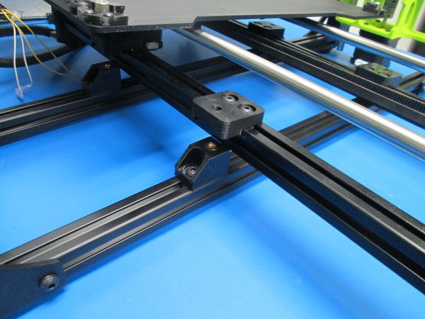
Set Y axis location fixtures into the frame extrusion top slots of the Y axis assembly nearest the motor (both sides of the motor) and into the top slot of the frame (front and back extrusion) to the left of the Y axis assembly
(Outside of Lulzbot manufacturing the Y axis assembly can be positioned by measuring 136mm from the edge of the aluminum extrusions to the edge Y chassis mounts, and 110mm from the edge of the Y corners to the edge of the table mounts).
Slide the mounts tight to the fixtures and the extrusions tight to the mounts at each fixture.
Secure the Y chassis mount M5 BHCS to the extrusion to 10in-lbs, then secure the table mounts (these are attached to the Y axis assembly) M5 BHCS to 10in-lbs.
Push the opposite side of the table's Y chassis mounts firmly against the extrusions and tighten the mounts to hand tight;
Push the opposite side table mounts firmly against the extrusions and tighten the mounts to 10in-lbs.
There should be NO space between the struts or mounts. Tighten the thumb screws.

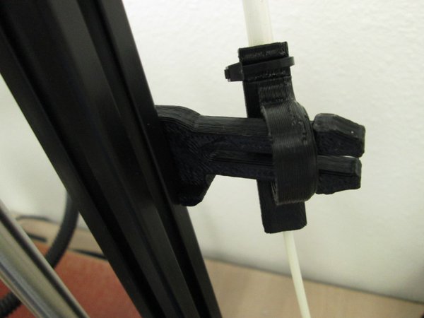
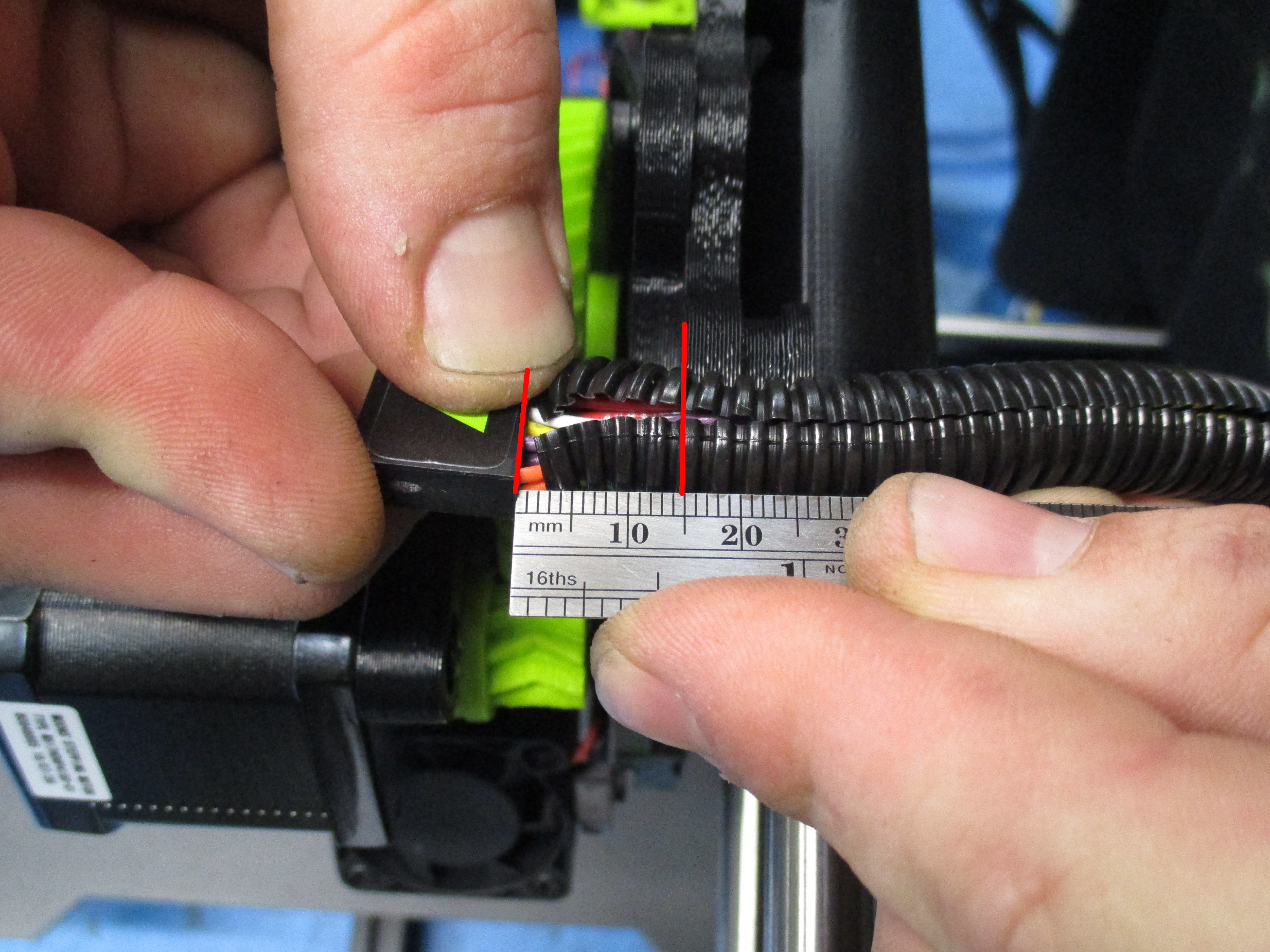
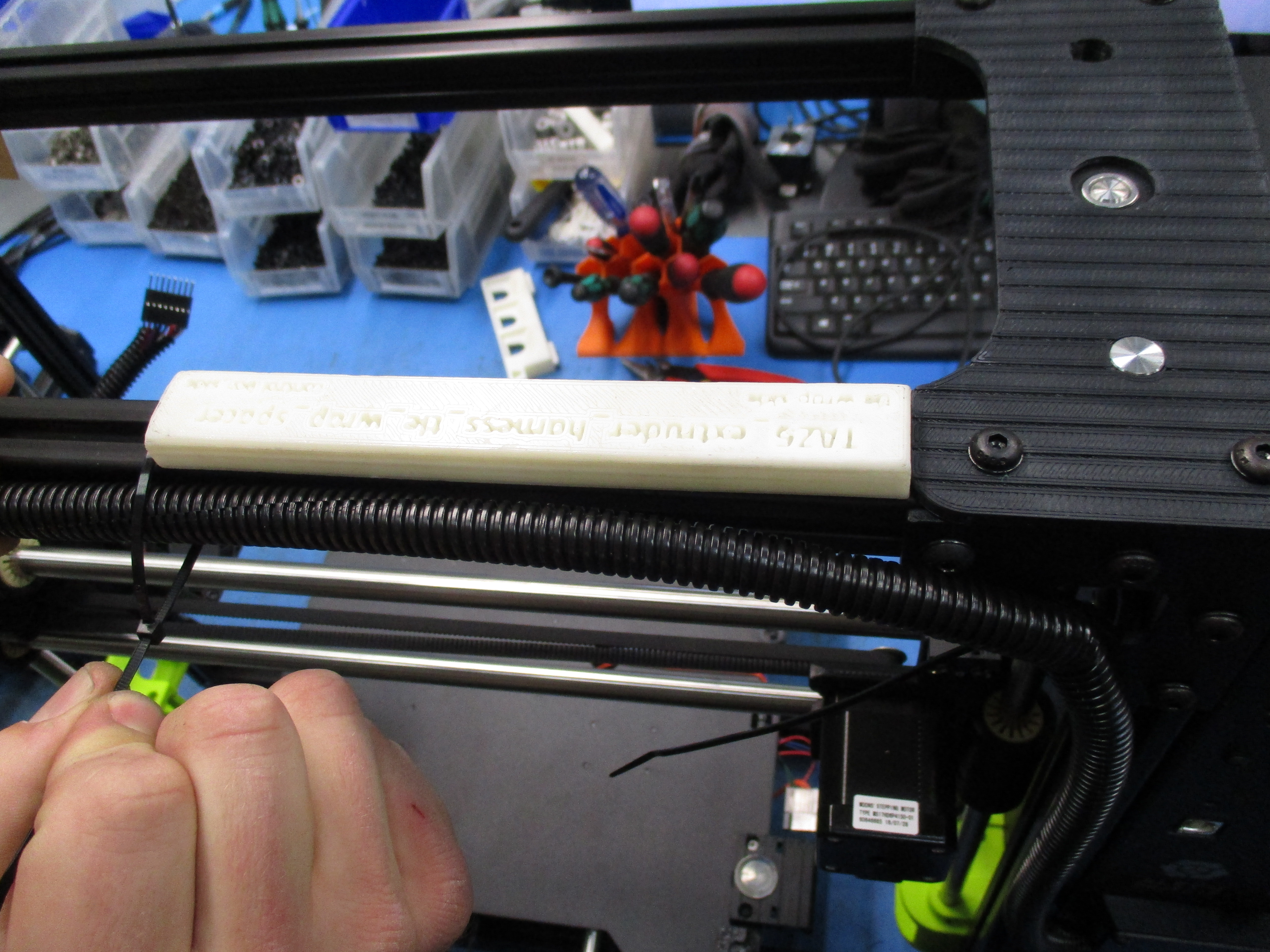
Place the extruder harness into the X carriage as shown and secure with a tie wrap and trim with flush cutters. Make sure to leave about 15mm of the harness on the x carriage.
Take the right Z motor harness and plug it into the left Z motor as shown.
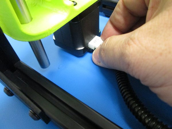
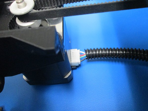
Plug the Y harness into the Y motor as shown.
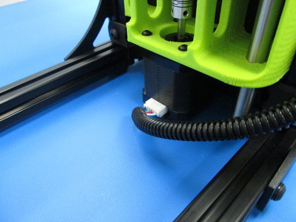
Plug the Right Z motor into the right Z motor as shown.
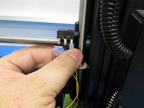
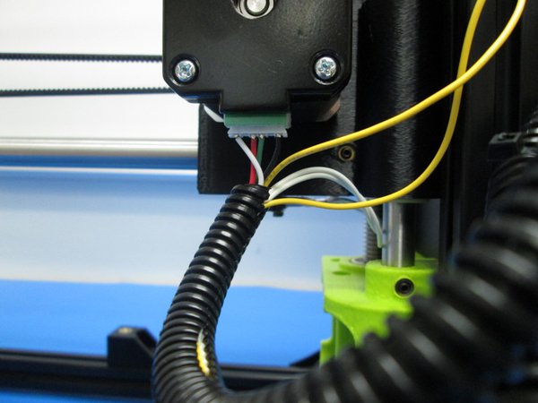
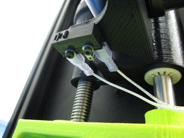
Take the X carriage harness and plug the yellow pair of wires and install them on the Z max switch making sure to use the outside pins on the switch.
Plug in the X motor.
Take the white pair of wires and install them onto the outside pins of the X min switch.
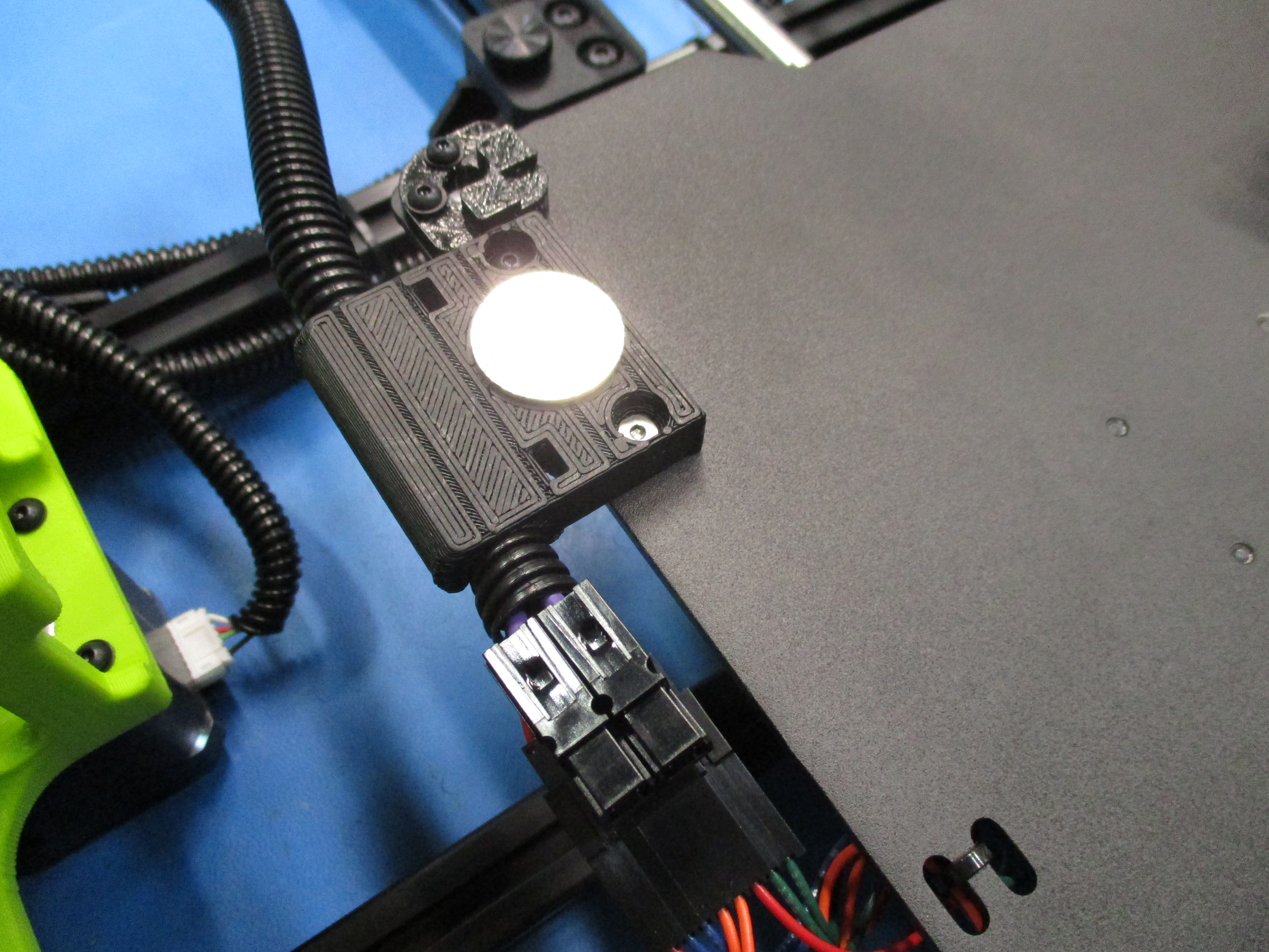
Connect the bed harness and push the harness into the clip as shown.
Use tie wraps in the following steps to secure the harnesses as shown. Make sure to keep a nice radius at each bend in the harnesses.
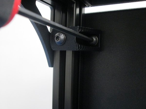
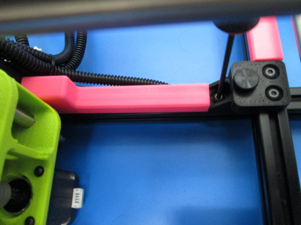
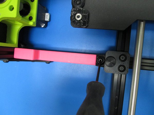
Leaving a nice radius to the extruder harness, secure the harness to the corner bracket.
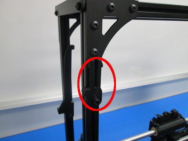
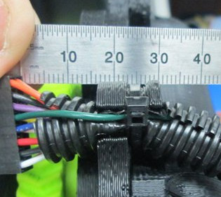
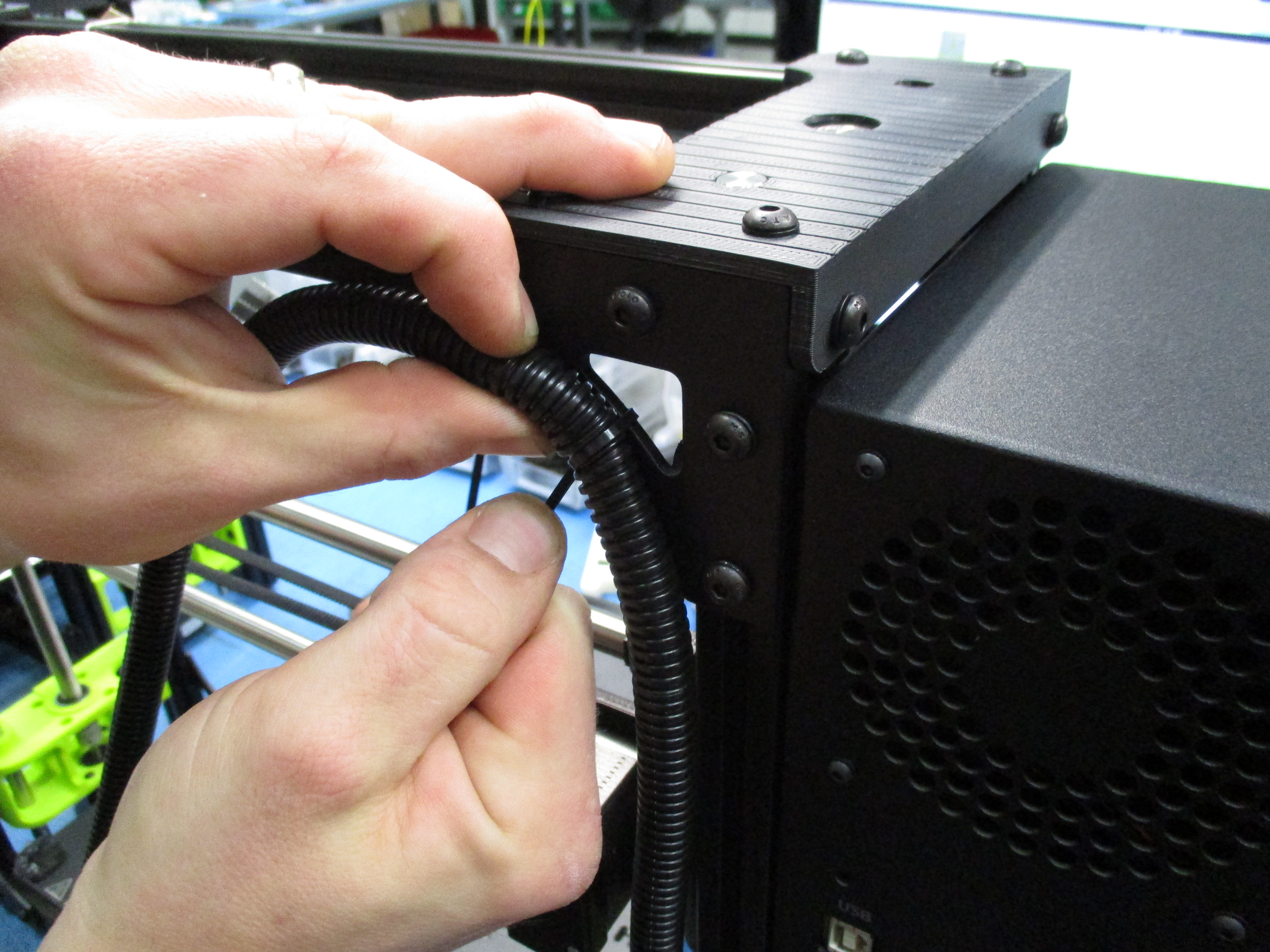
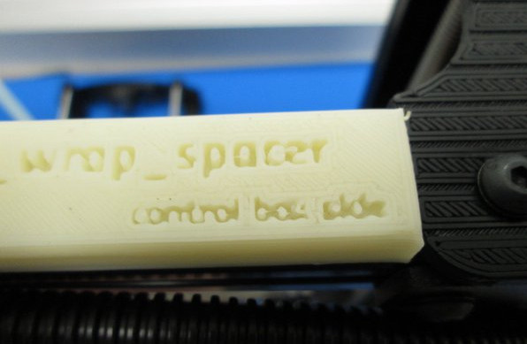
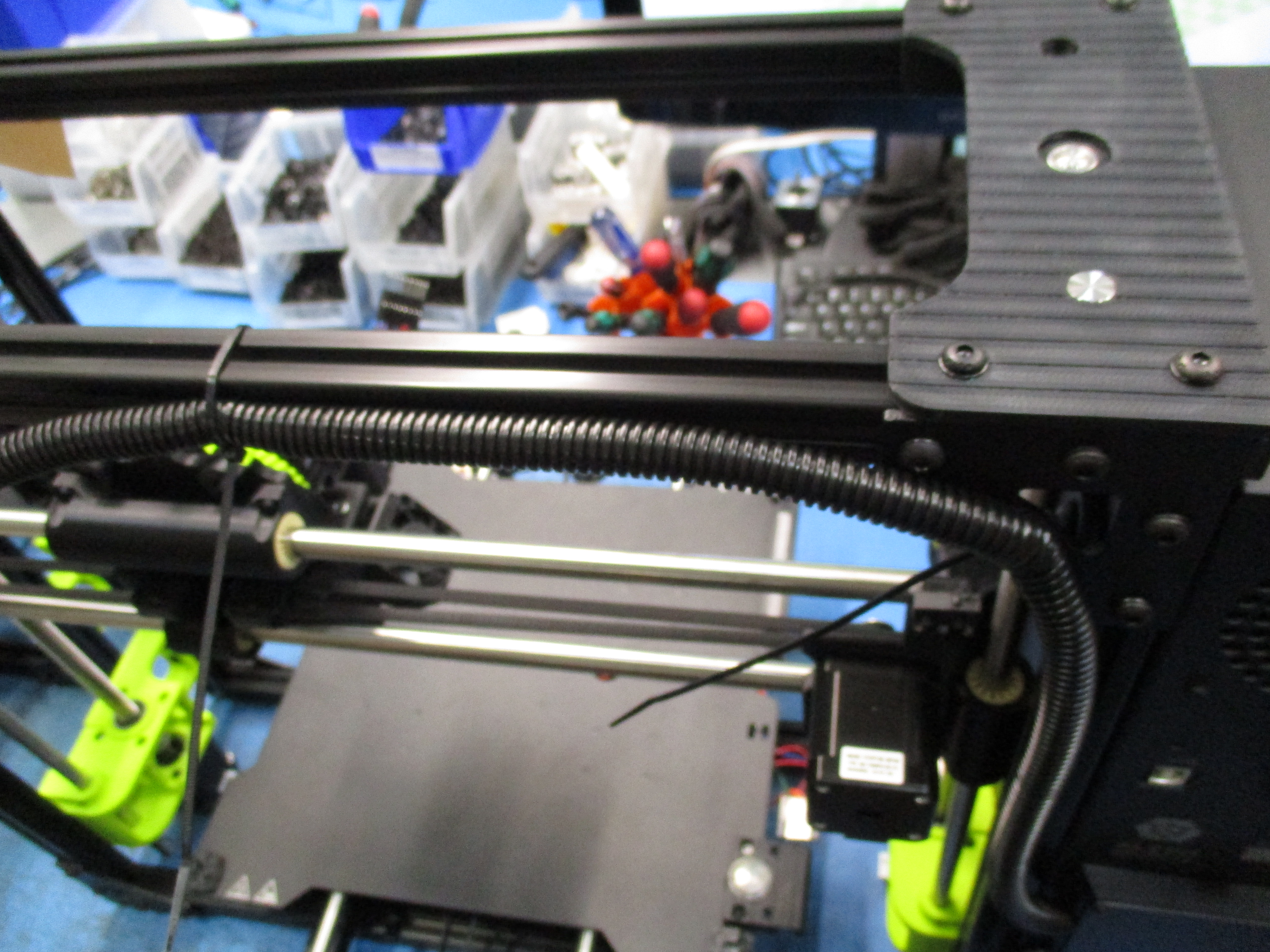
Secure the rest of the harness to the backside of the frame 155mm from the edge of the left top drive by measure or using a jig as shown.
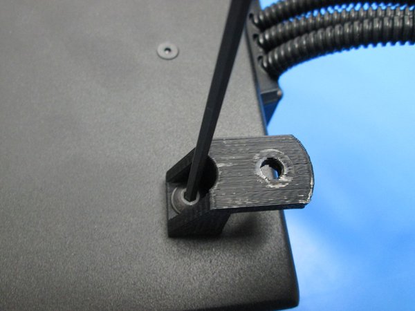
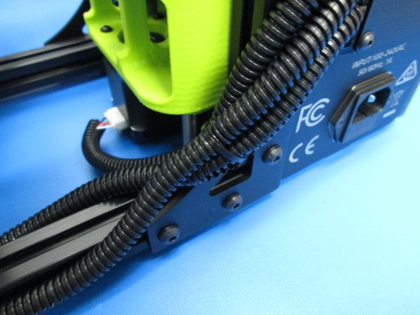
Secure the two Z, and the Y motor harness to the lower corner bracket.
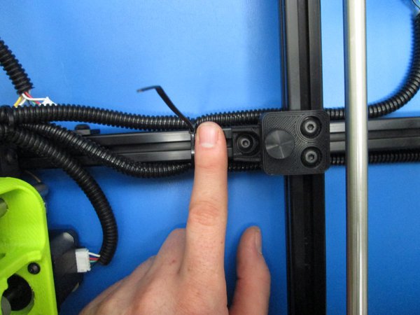
Tie wrap the Z and Y harnesses to the lower rear extrusion leaving a fingers width of space between the tie wrap and the mount.
Tie wrap the Y harnesses to the lower rear extrusion leaving a fingers width of space between the tie wrap and the mount.
Tie wrap the Z harnesses to the lower rear extrusion leaving a fingers width of space between the tie wrap and the mount.
There should be a nice liberal radius at each turn in the harnesses to prevent premature wear and motor disconnections.
Cut the excess of the tie wraps using flush cutters.
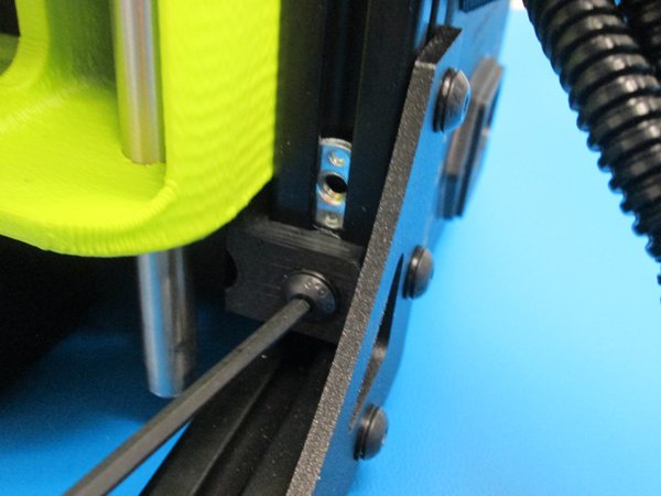
Install the tool head on the X carriage making sure to put the bottom of the mount into the guide at the bottom of the carriage. Secure with an M3X12SHCS tighten finger tight.
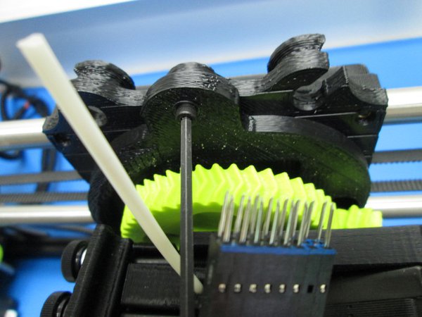
Plug in the tool head. Make sure the the sides with the missing pin position are on the same side.
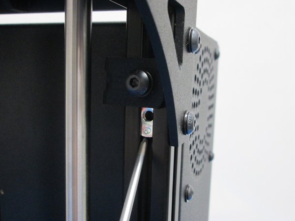
Install the spool arm as shown using one M5X12 SCHS and an M5 black washer . Tighten hand tight.
Install the feed tube spinner as shown.