Open HardwareAssembly Instructions
Guides for installation and assembly of the LulzBot line of products made by FAME 3D LLC.
Guides for installation and assembly of the LulzBot line of products made by FAME 3D LLC.
8x- [HD-BT0039] M3x12 SHCS, Black-Oxide
12x- [HD-BT0073] M5x10 BHCS, Black-Oxide
4x- [HD-BT0157] M3x8 SHCS, Black-Oxide
4x- [HD-BT0272] M5x20 BHCS, Black-Oxide
2x- [HD-MS0033] 16 Teeth Timing Pulley
2x- [HD-MS0411] Premium Two Side Rubber Sealed Bearing
12x- [HD-NT0053] M5 T-Slot Nut
8x- [HD-WA0038] M3 Washer
2x- [HD-EX0098] T-Slot Extrusion 334mm
2x- [EL-MT0068] NEMA 17 Stepper Motor
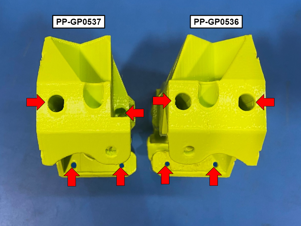
1x- [PP-GP0536] Z Lower Right
1x- [PP-GP0537] Z Lower Left
1x- [PP-GP0543] Y Axis Frame Mount
1x- SK 747 Power Supply assembly

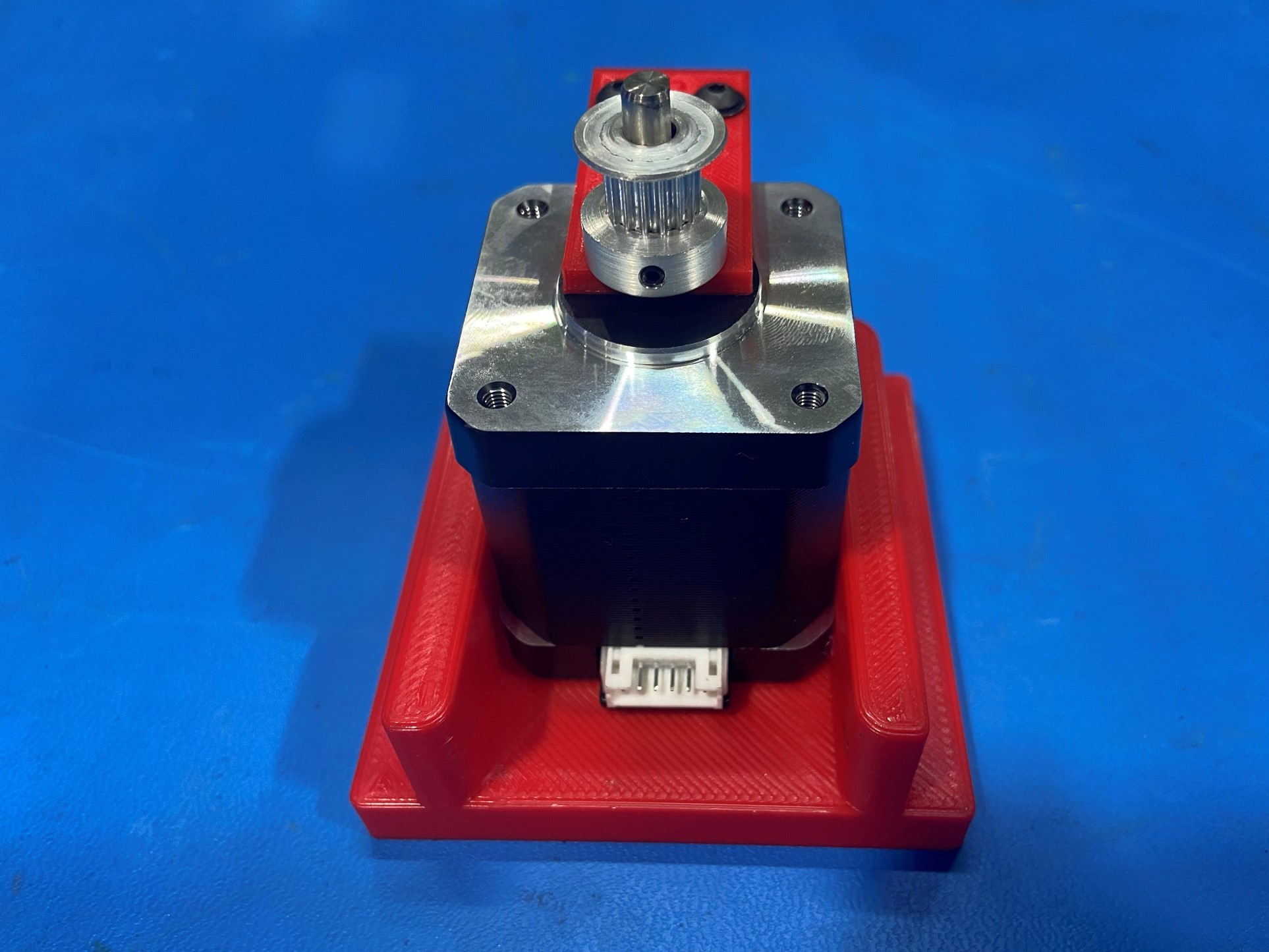
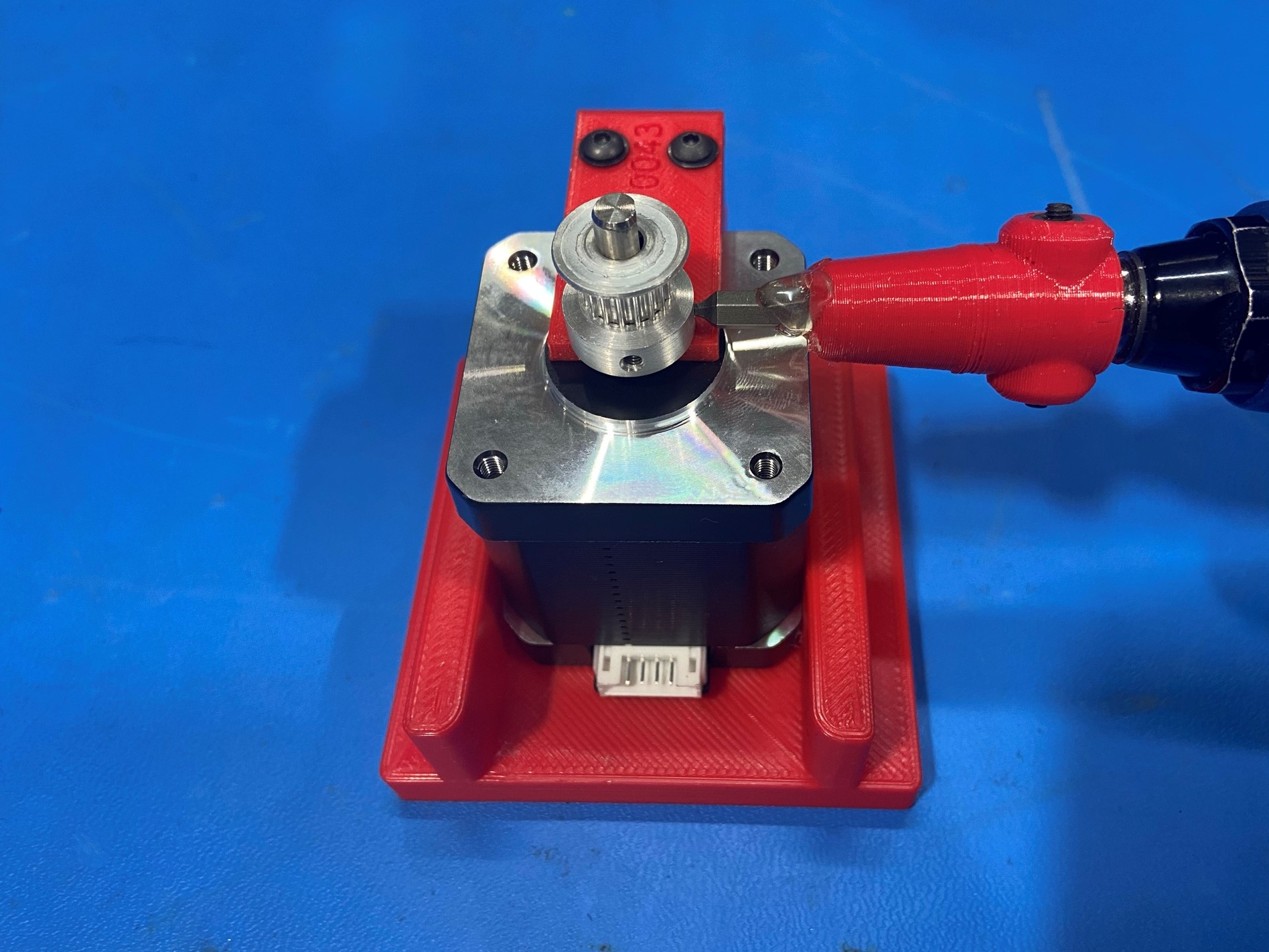
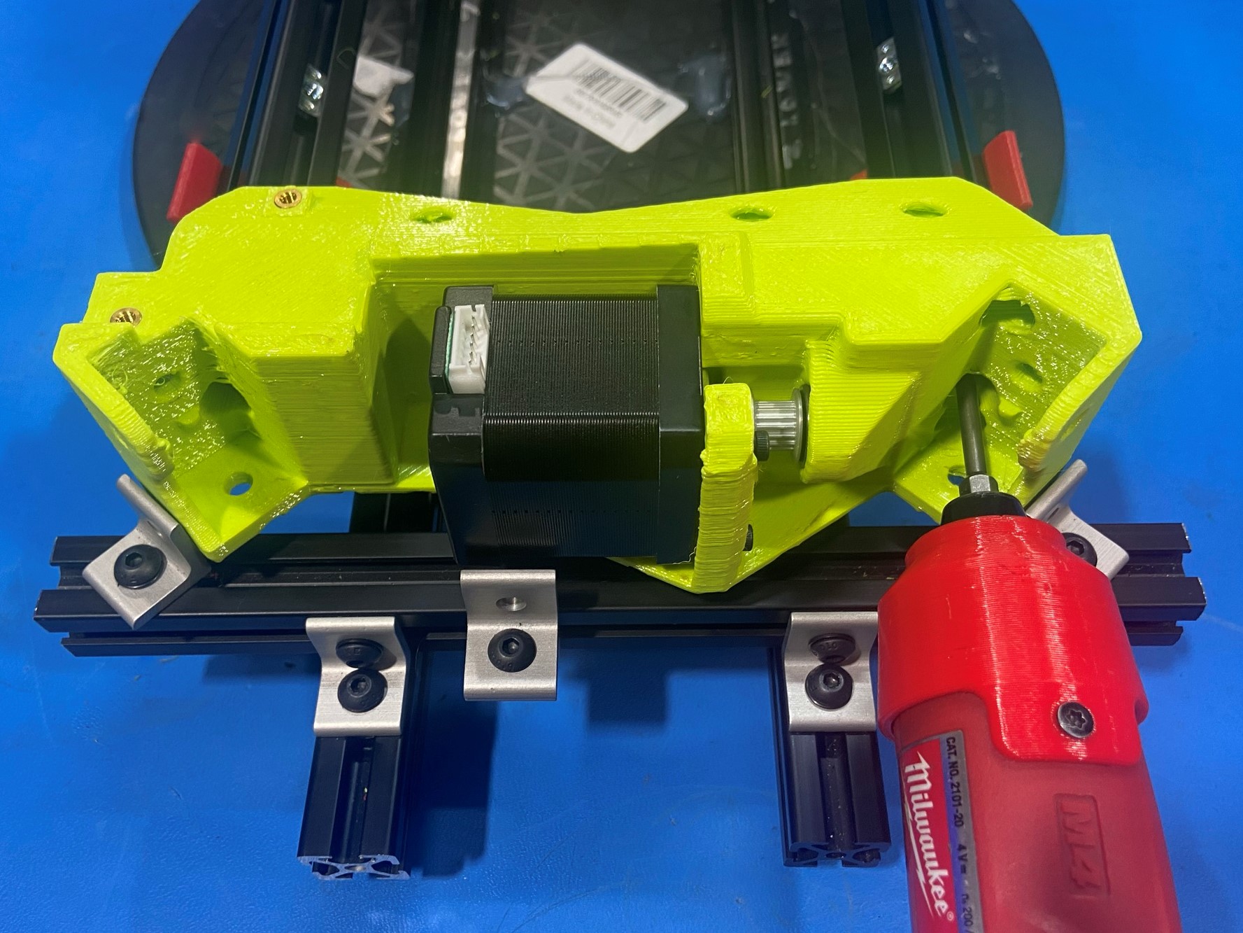
Place 1x NEMA 17 stepper motor [EL-MT0068] inside the Z lower motor jig, then slide 1x 16 teeth timing pulley [HD-MS0033] on the motor shaft making sure one of the set screws on the pulley is aligned with the flat side of the motor shaft.
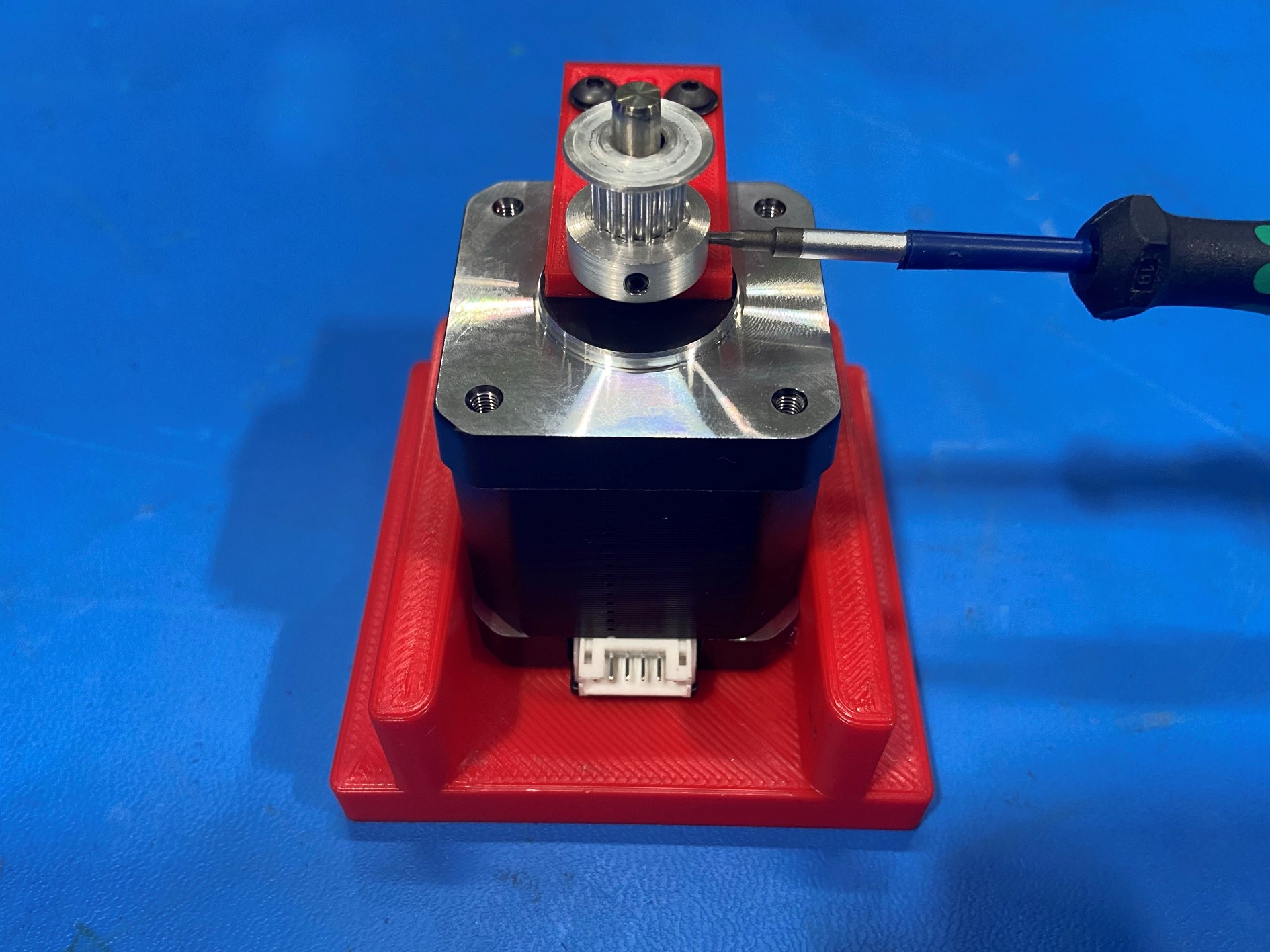
While pushing down on the timing pulley tighten both set screws. Then torque the set screws to 3 in*lb.
Repeat these steps for the second stepper motor.
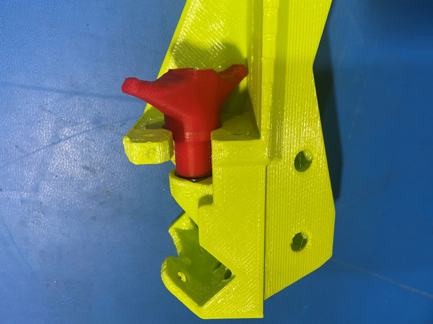
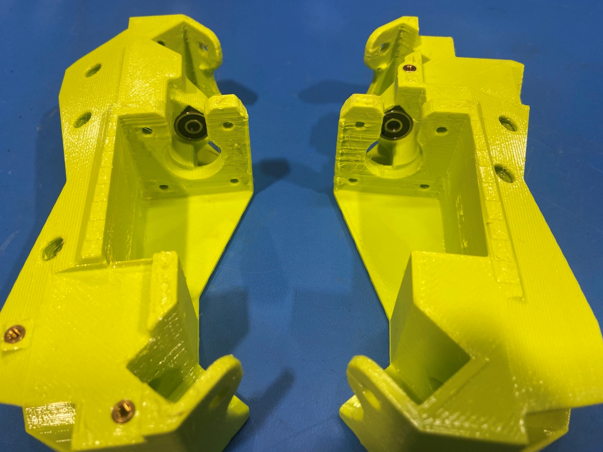
Using the bearing punch jig and 1x rubber sealed bearing [HD-MS0411] and Z lower right [PP-GP0536] press the bearing into the teardrop shaped hole [reference#1]
Repeat for Z lower left [PP-GP0537]


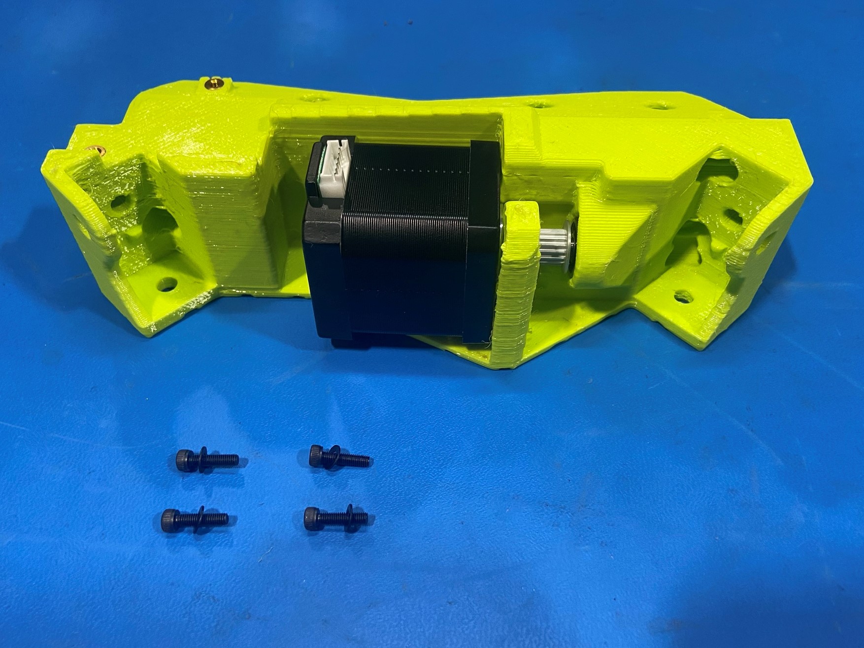
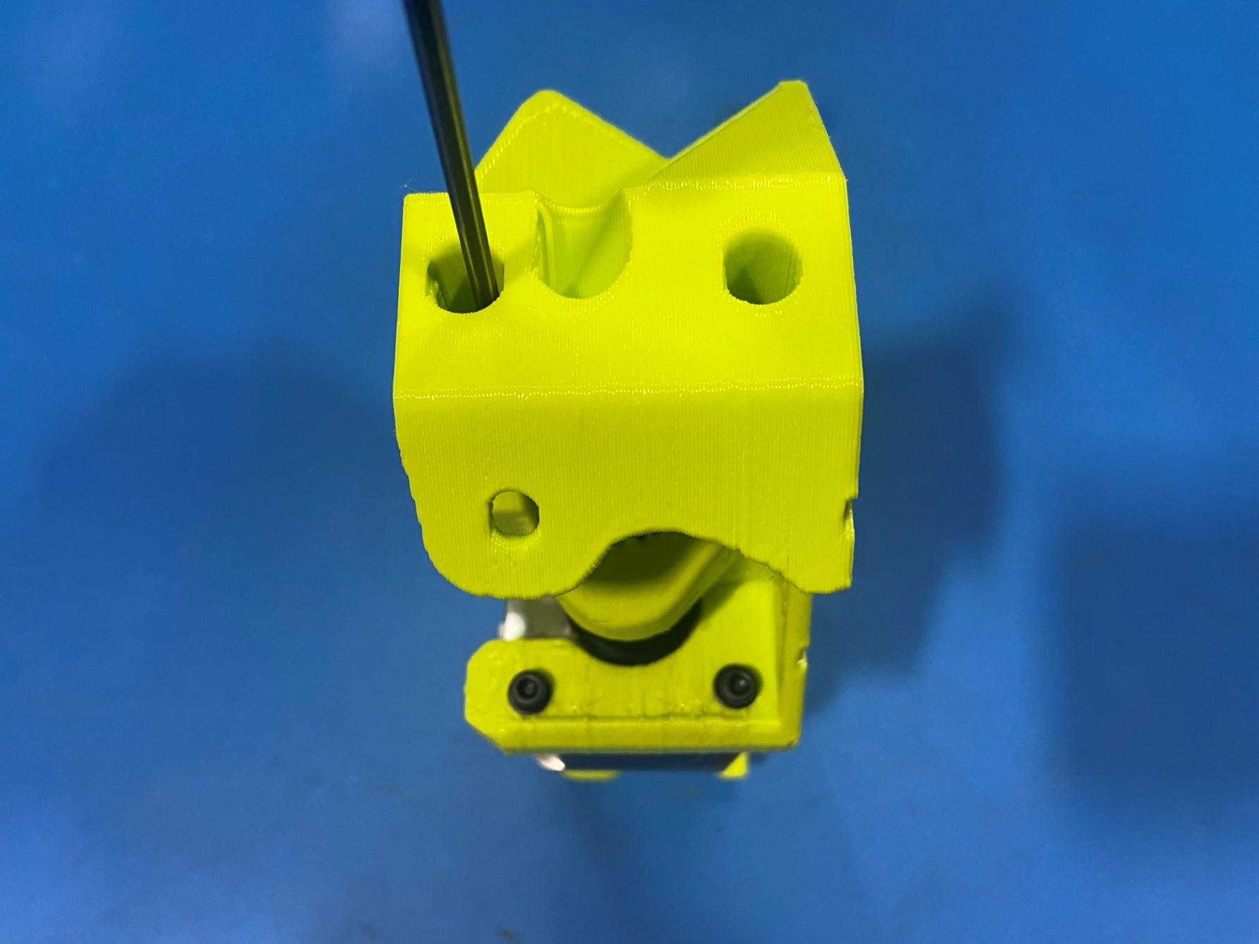
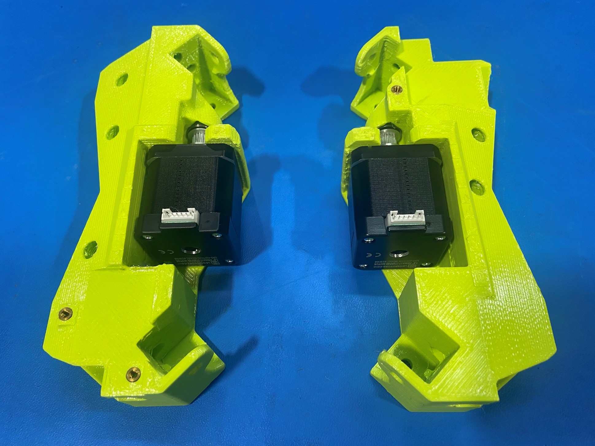
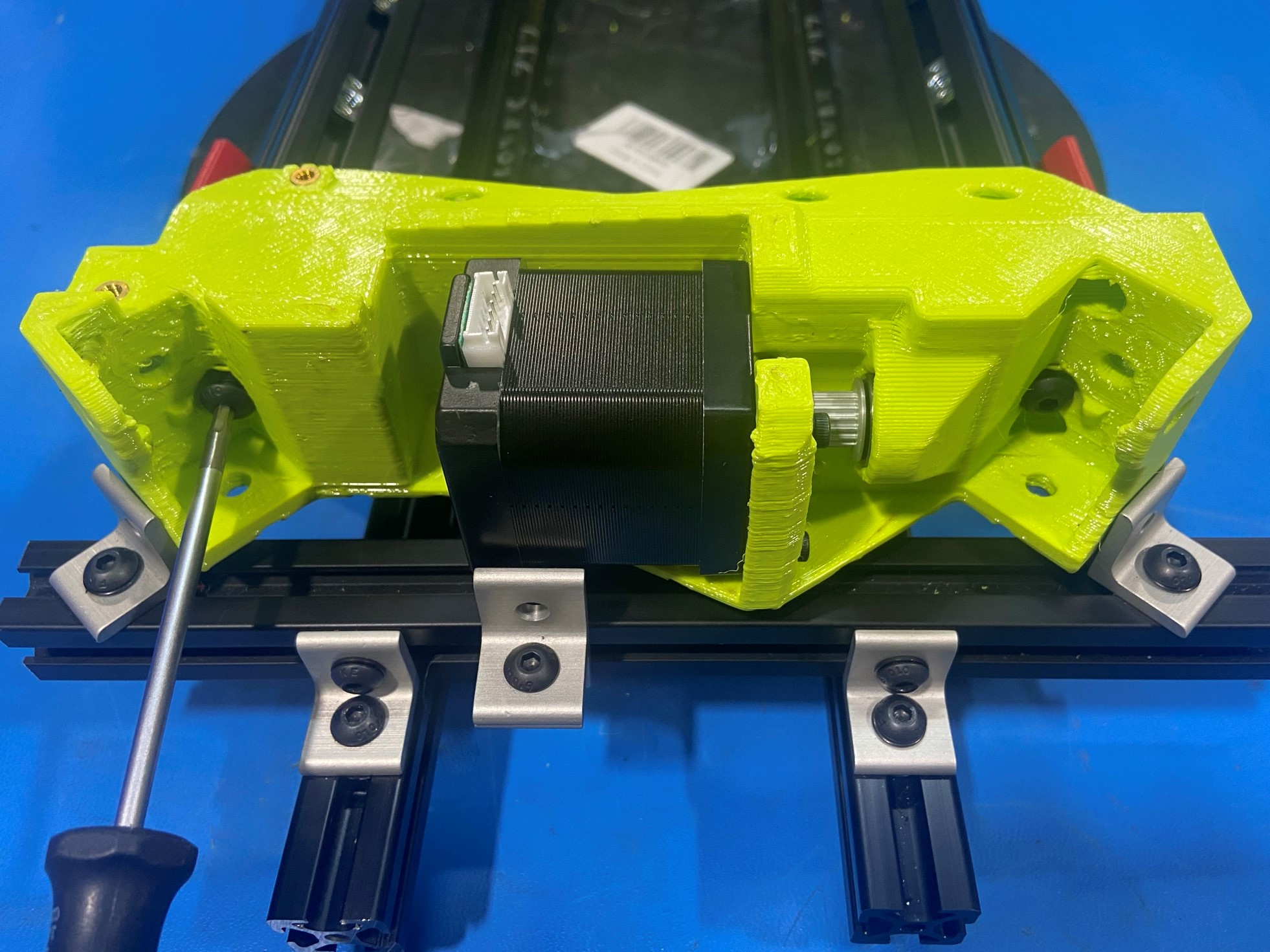
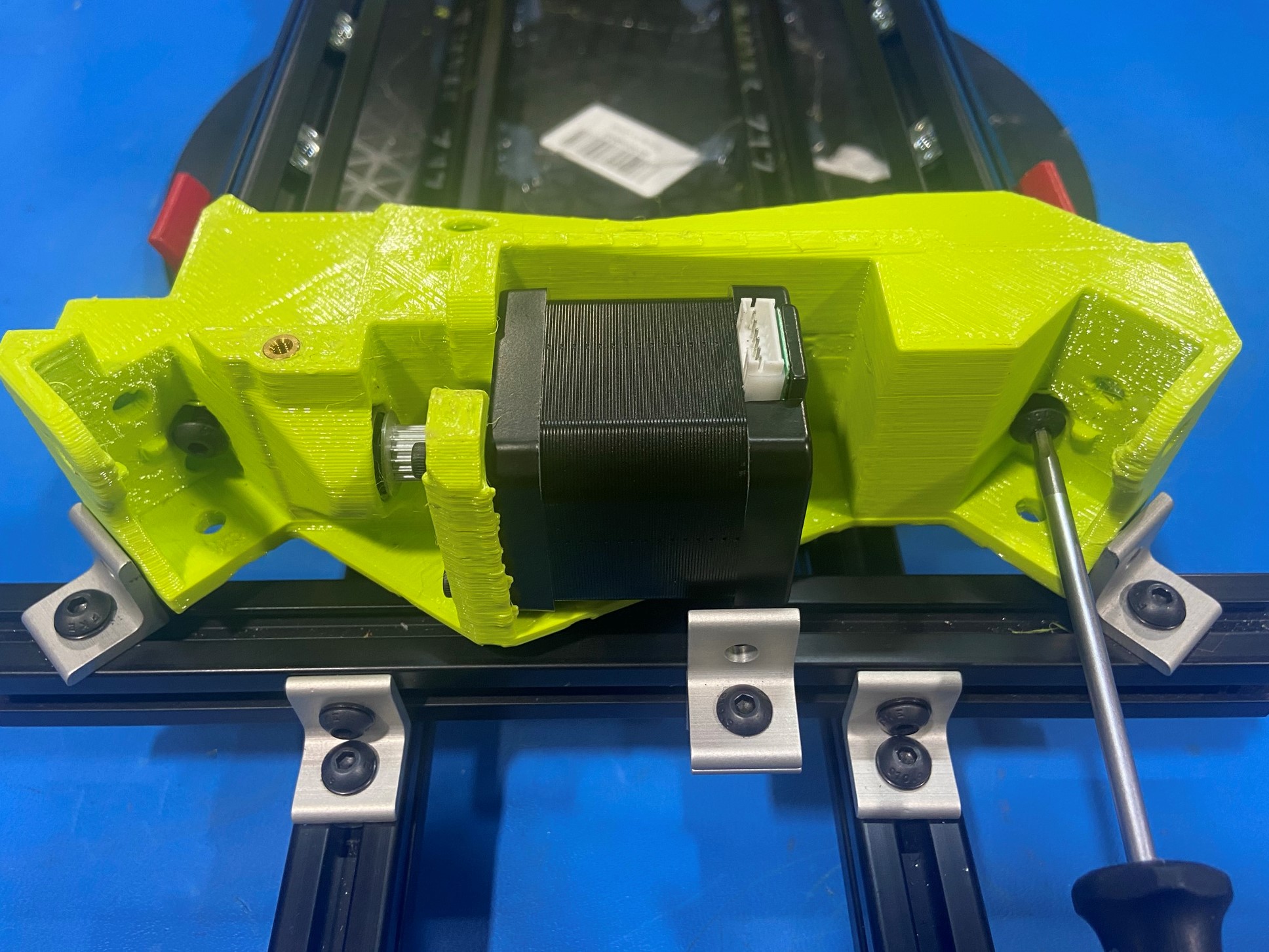
Place 1x NEMA stepper motor inside Z lower left making sure the shaft is sitting in the rubber sealed bearing and the motor connector is facing up.
Then using 4x M3x12 SHCS [HD-BT0039] with 4x M3 washers [HD-WA0038] secure the motor to the Z lower.
Repeat these steps using Z lower right.
Then route a scrap belt around the motor and pull on one side of the belt to check if the bearing and pulley rub together.
Note: If the bearing and pulley are rubbing together you will feel a jerking while pulling on the belt, if this happens remove motor and reinstall the bearing.
Check the second motor on the other Z lower.

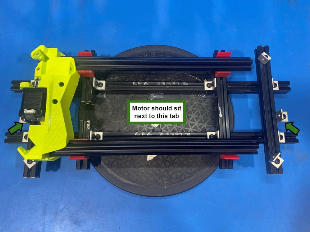
Place the Z lower right with motor inside the 747 Z lower jig making sure the motor is sitting next to the middle metal tab.
Then use 2x T-Slot Extrusion 334mm [HD-EX0098] and slide them into the Z lower right. Then following [reference#3] slide 12x T-Slot nuts into the extrusions.
Place the Z lower left on the other ends of the extrusions and place them in the 747 Z lower jig.
Start to fasten 2x M5x20 BHCS [HD-BT0272] into the extrusion to secure the Z lower left, then repeat for the Z lower right.
Note: Make sure to leave the screws loose until all four are half way in the extrusion
Once all four M5x20 BHCS are in place then use the drill to fully secure the Z lowers to the extrusions
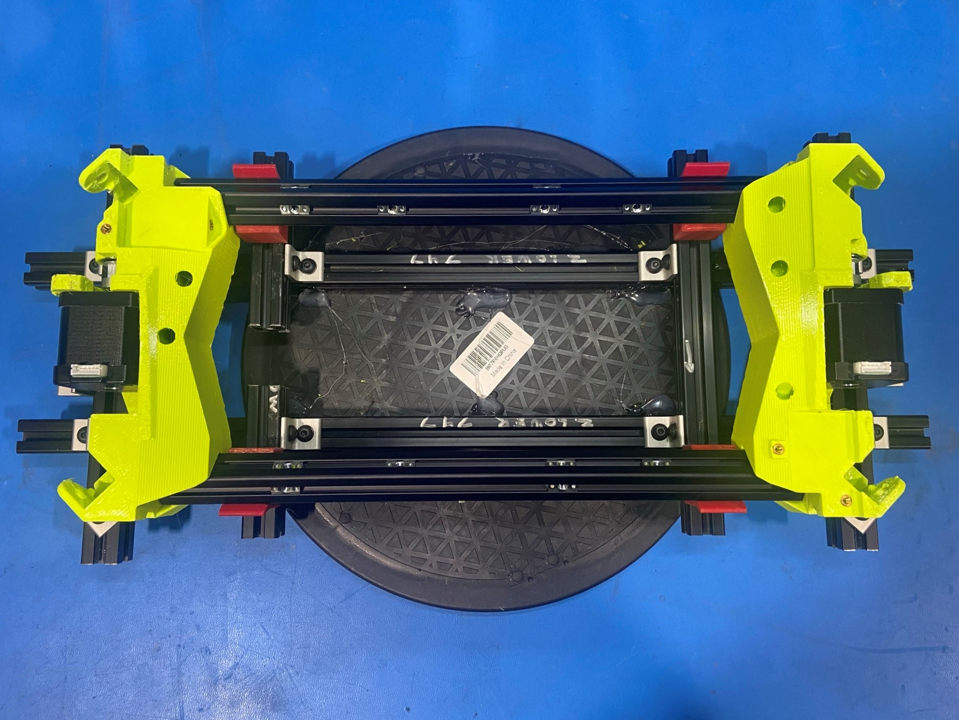
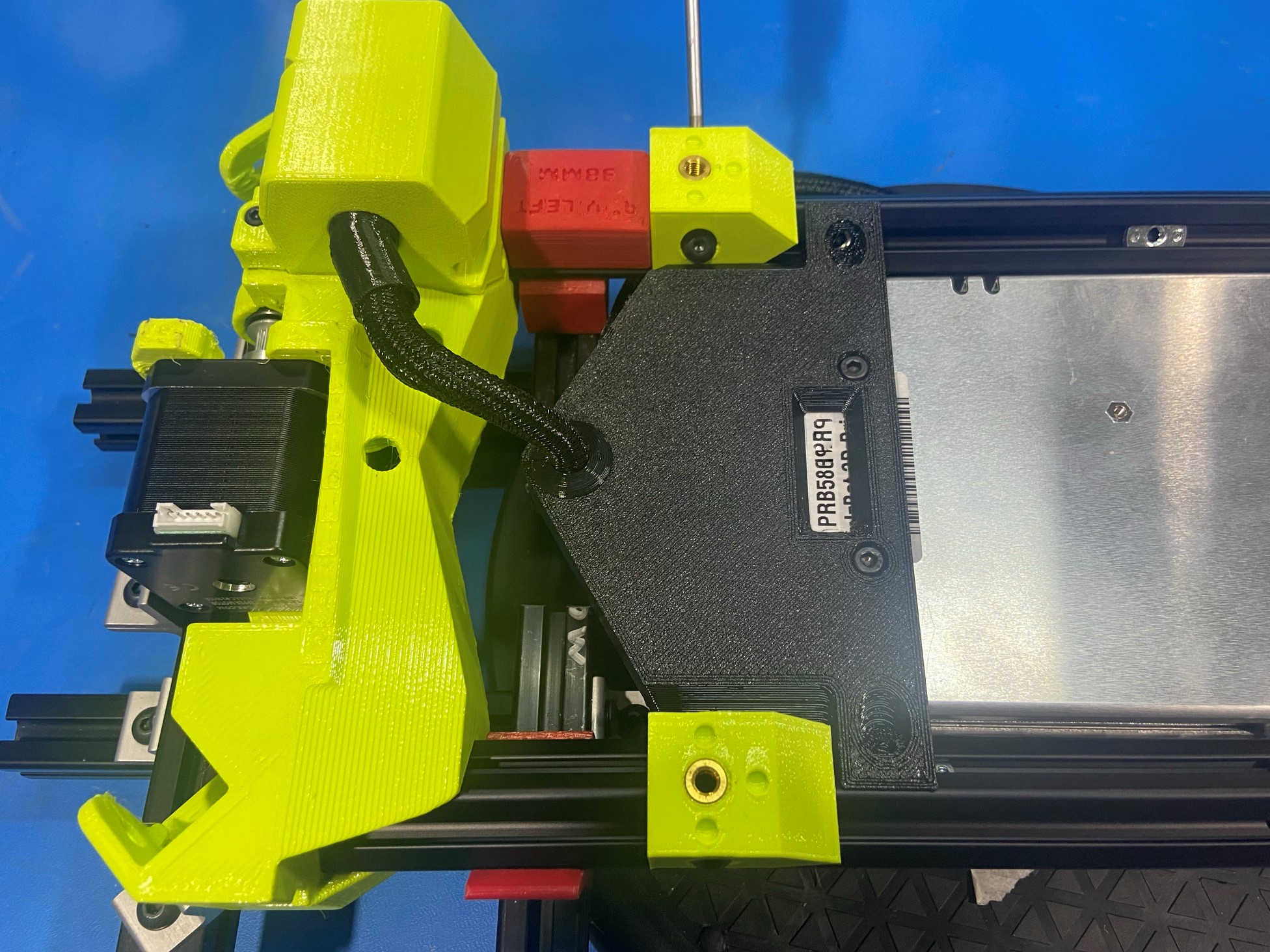
Place the power supply assembly in between the extrusions making sure the power supply assembly points towards the Z lower left. Make sure the power switch wire harness is under the extrusions.
Then using 4x M5x10 BHCS [HD-BT0073] secure the power supply to the extrusions, if needed use a tweezer to align the T-nuts.
Note: Follow [reference#4] when mounting the power supply to the extrusions
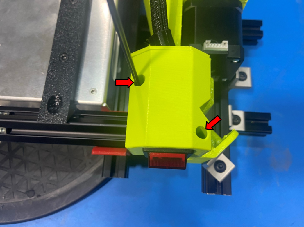
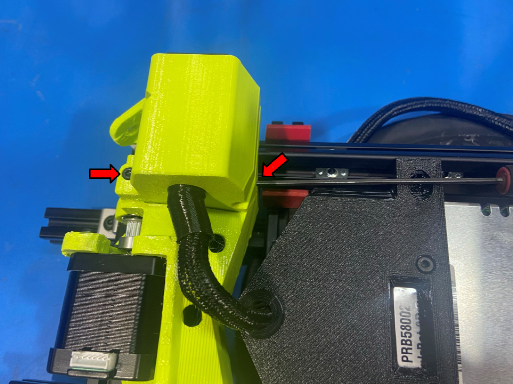
Then using 2x M3x10 SHCS **[HD-BT0157] secure the power switch housing to the Z lower right, and repeat process to mount the power plug housing to the Z lower left.
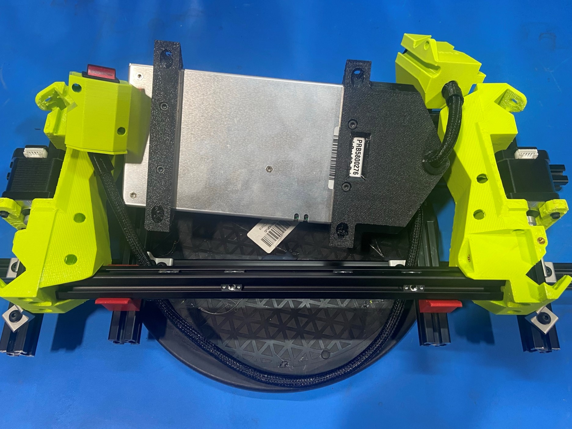


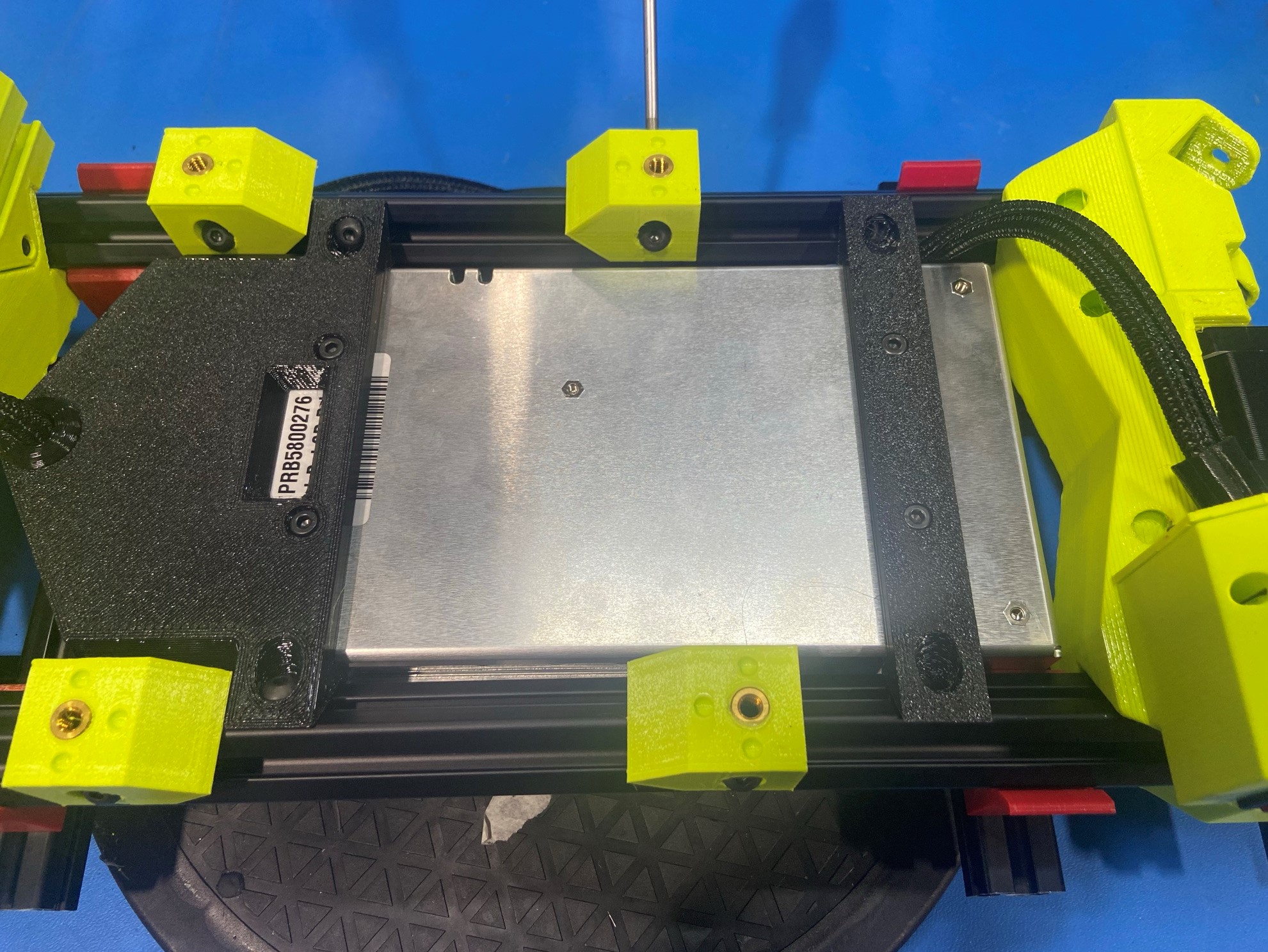
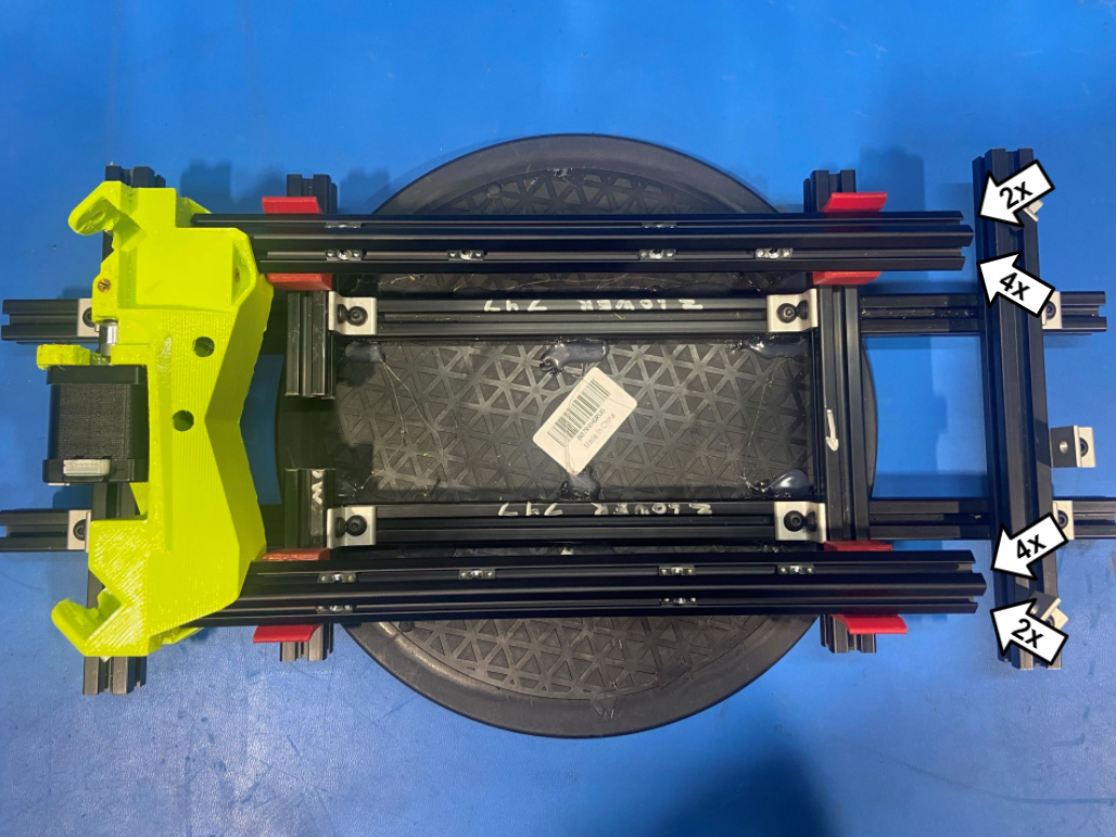
Using a total of 8x M5x10 BHCS [HD-BT0073] secure the 4x Y axis frame mount [PP-GP0543] to the extrusions.
Use the 747 frame mount spacing jig when fastening the two frame mounts next to the Z lower left.
Leave the other two frame mount loose, these will be tightened in calibration.