Open HardwareAssembly Instructions
Guides for installation and assembly of the LulzBot line of products made by FAME 3D LLC.
Guides for installation and assembly of the LulzBot line of products made by FAME 3D LLC.
1x- [EL-MT0068] NEMA 17 Stepper Motor
1x- [HD-BL0032] Single Sided Neoprene Belt
4x- [HD-BT0005] M3x10 SHCS
2x- [HD-BT0007] M3x20 SHCS
6x- [HD-BT0039] M3x12 SHCS
4x- [HD-BT0130] M3x8 FHCS
4x- [HD-BT0148] M3x10 BHCS
2x- [HD-BT0263] M5x12 SHCS
1x- [HD-BT0266] M4x30 HHCS
5x- [HD-BT0272] M5x20 BHCS
2x- [HD-EX0096] T-Slot Extrusion 400mm
1x- [HD-MS0033] 16 Teeth Timing Pulley
1x- [HD-MS0411] Premium Two Side Rubber Sealed Bearing
1x- [HD-MS0593] 5mm Smooth Bore Idler
4x- [HD-NT0001] M3 Nut
2x- [HD-NT0053] T-Slot Nut
4x- [HD-WA0038] M3 Washer
5x- [HD-WA0040] M5 Washer
1x- [PP-FP0220] SK Octoluminum Bed Plate 289
4x- [PP-GP0533] Flexy Bed Corner
1x- [PP-GP0540] Y Idler
1x- [PP-GP0544] Y Motor Mount
1x- [PP-GP0546] Y Belt Mount
1x- [PP-GP0557] XYZ Tensioner Knob
1x- [PP-GP0581] XY Belt Tensioner
1x- [PP-GP0634] Bed Center Post
2x- [PP-GP0644] Flexy Cushion Y Idler
4x- [PP-GP0651] Bed Corner Cover
4x- [PP-GP0652] Bed Corner Base
2x- [PP-GP0692] Y Axis Placement Block
1x- Y Carriage Subassembly

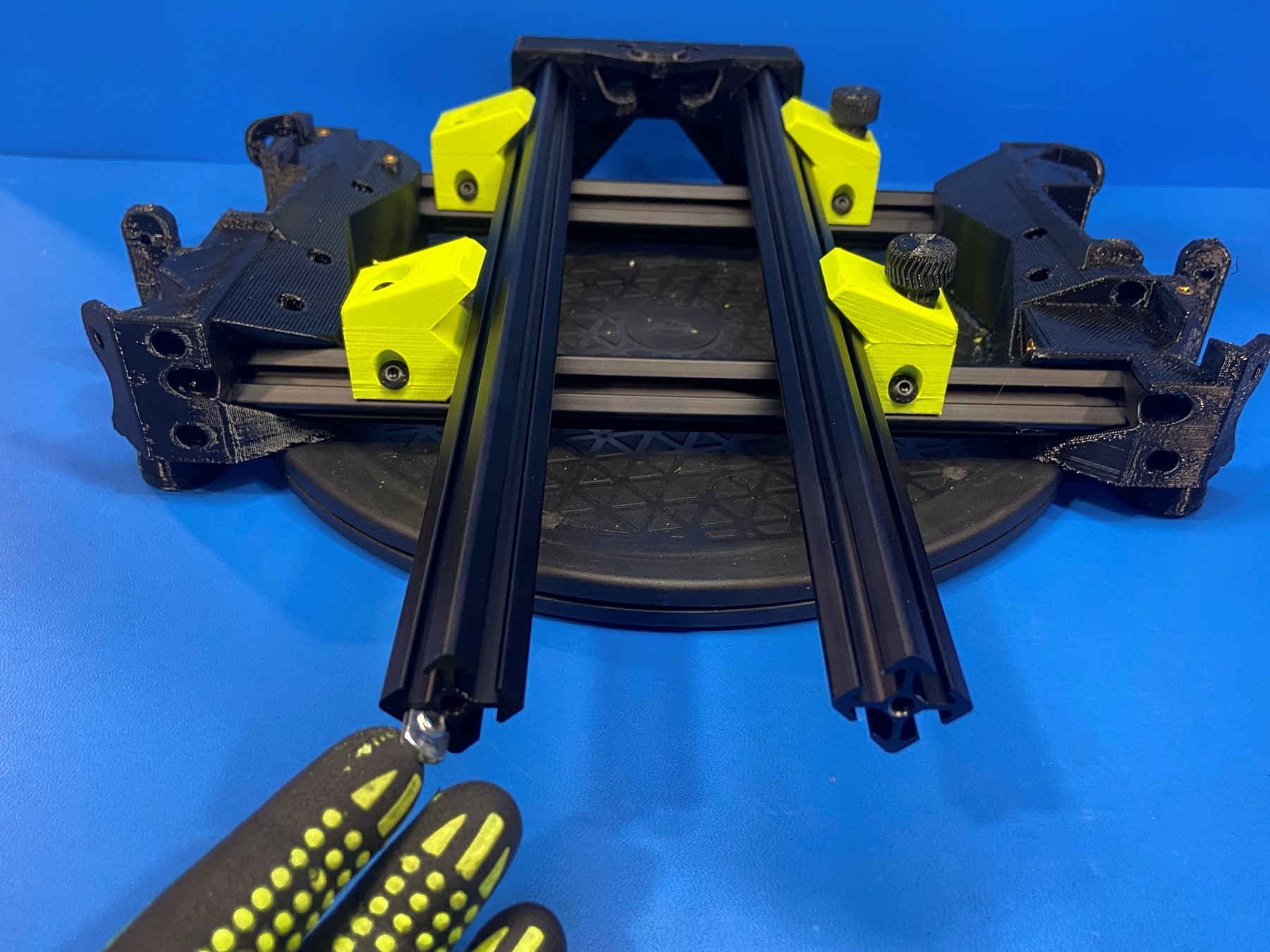
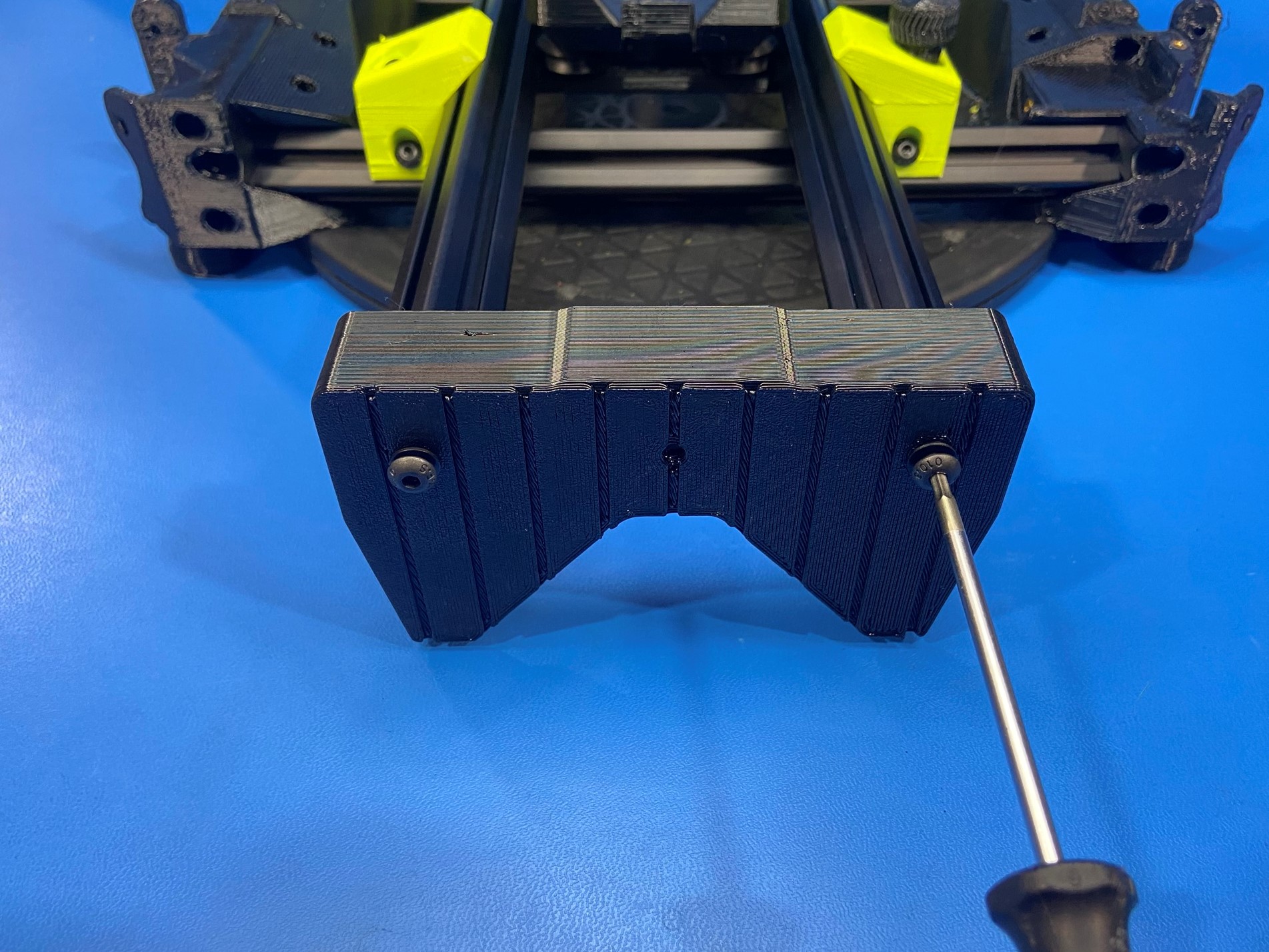
Slide 2x T-slot extrusions 400mm [HD-EX0096] into the two square holes on the Y motor mount [PP-GP0544] then loosely fasten 2x M5x20 BHCS [HD-BT0272] with 2x M5 washers [HD-WA0040].
Loosen the two right brackets on the Y axis fixture that is on the turntable and place the extrusions inside the brackets. Once the extrusions are seated inside tighten the two right brackets to secure the Y axis.
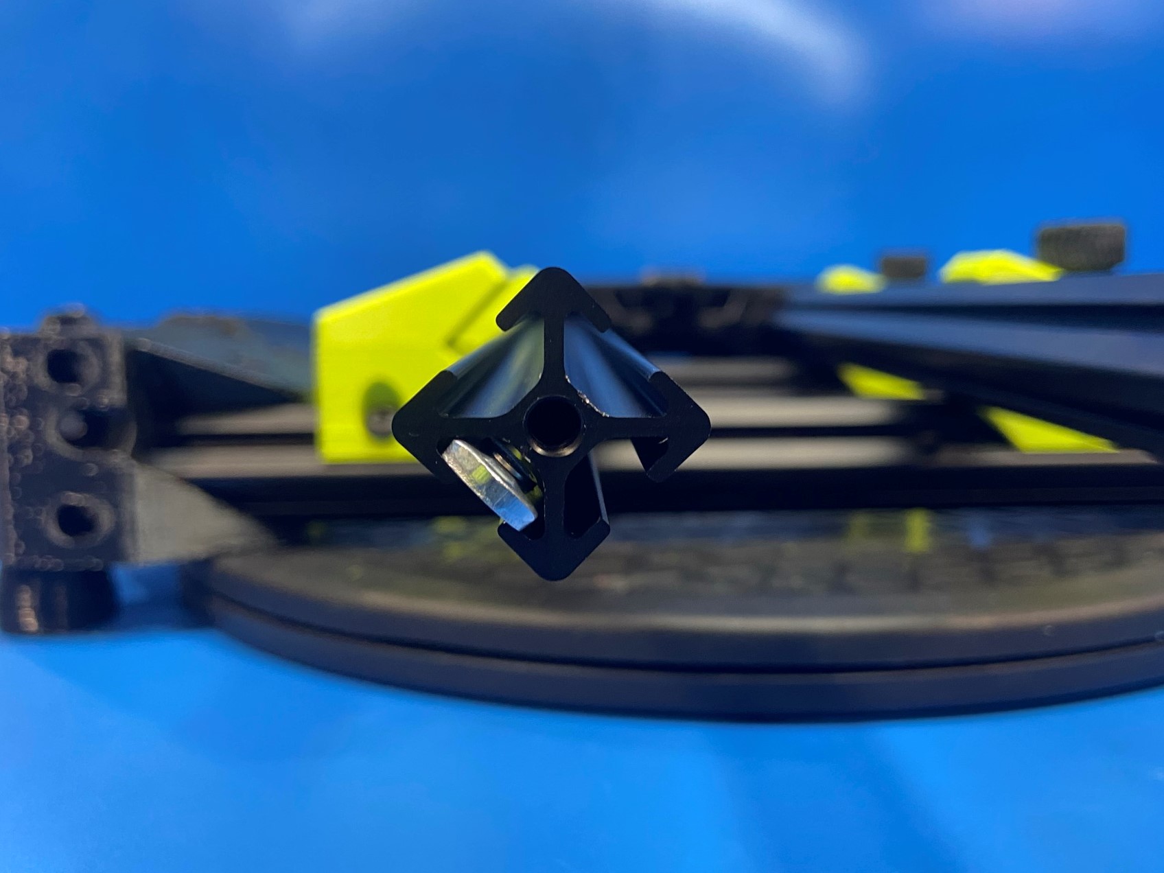
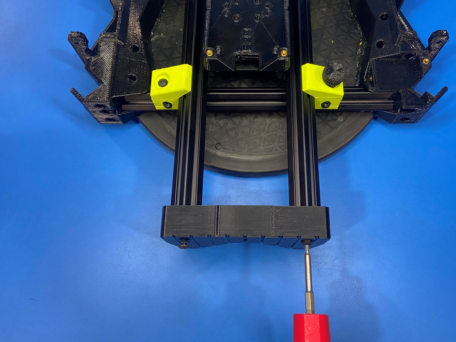
Slide 2x T-slot nuts [HD-NT0053] inside the bottom left side of the left extrusion making sure the Y motor mount is in the back.
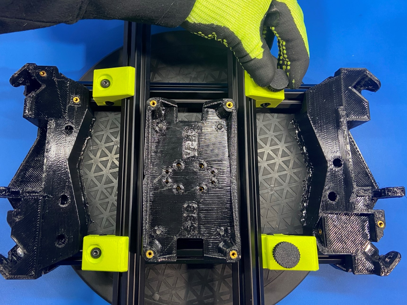
Now slide the Y carriage subassembly in-between the extrusions making sure the top side is facing up.
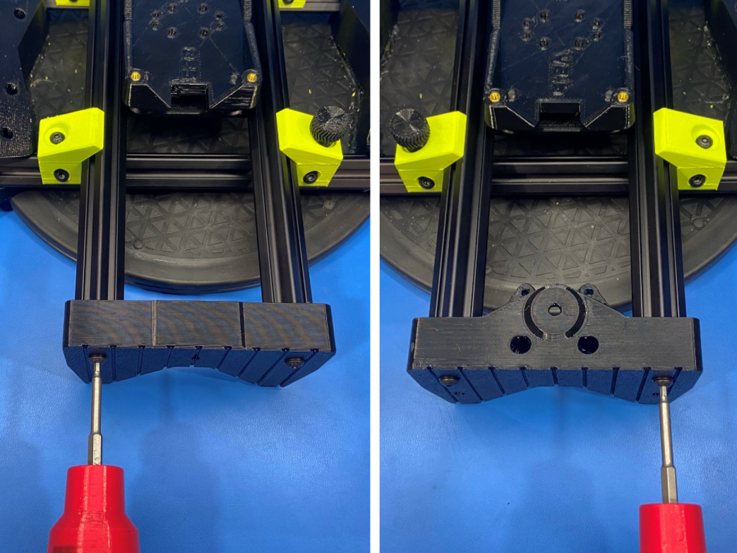
Then place the Y idler [PP-GP0540] over the two extrusions and loosely fasten 2x M5x20 BHCS [HD-BT0272] with 2x M5 washers [HD-WA0040] into the extrusions.
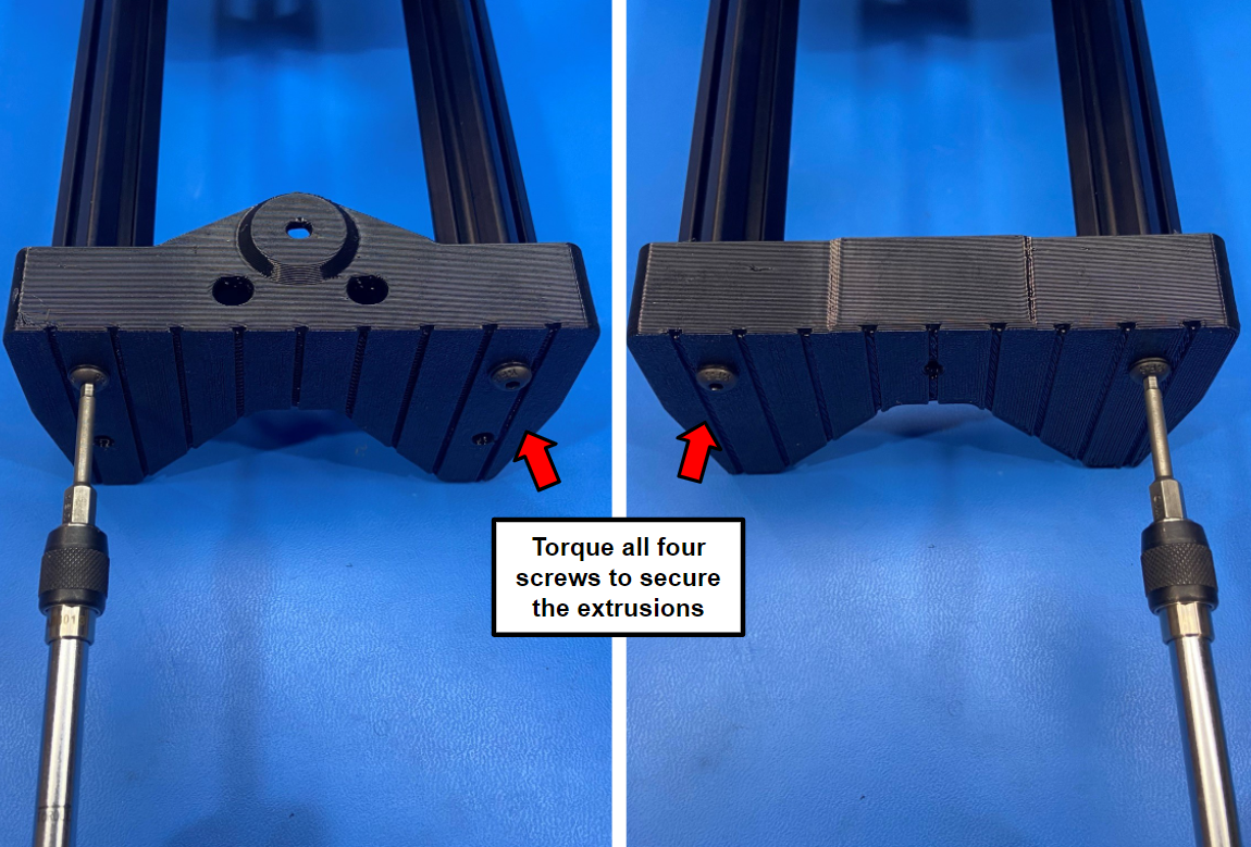
Once both ends are attached to the extrusions and the Y carriage is sitting the in the middle use the drill to tighten each extrusion to the Y idler and Y motor mount.
Make sure to tighten one extrusion on both ends then move to second
Once both extrusions are secure loosen the two right brackets and remove the Y axis from the Y axis fixture.
Then torque all four screws to 16in*lbs


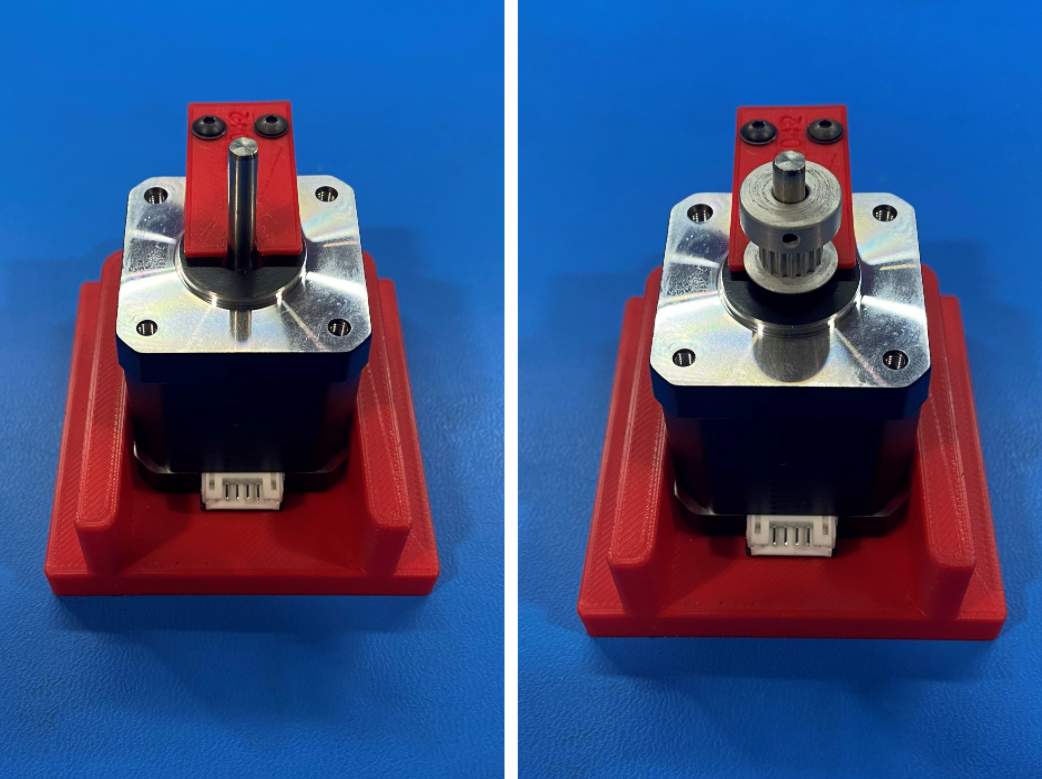
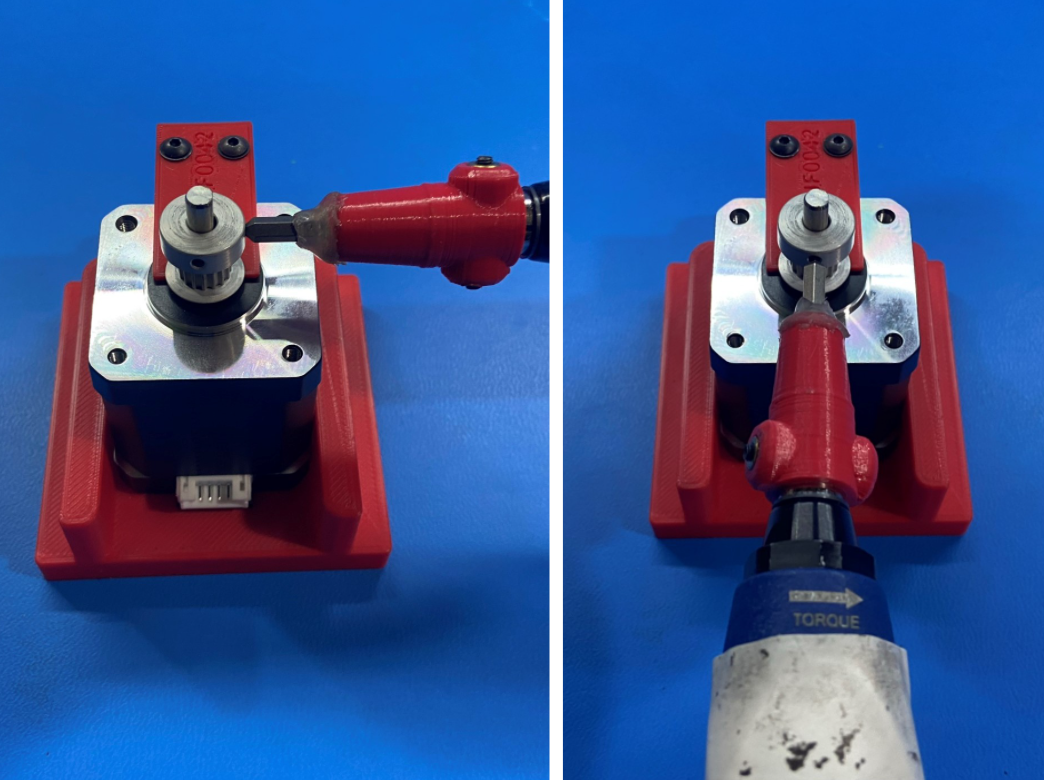
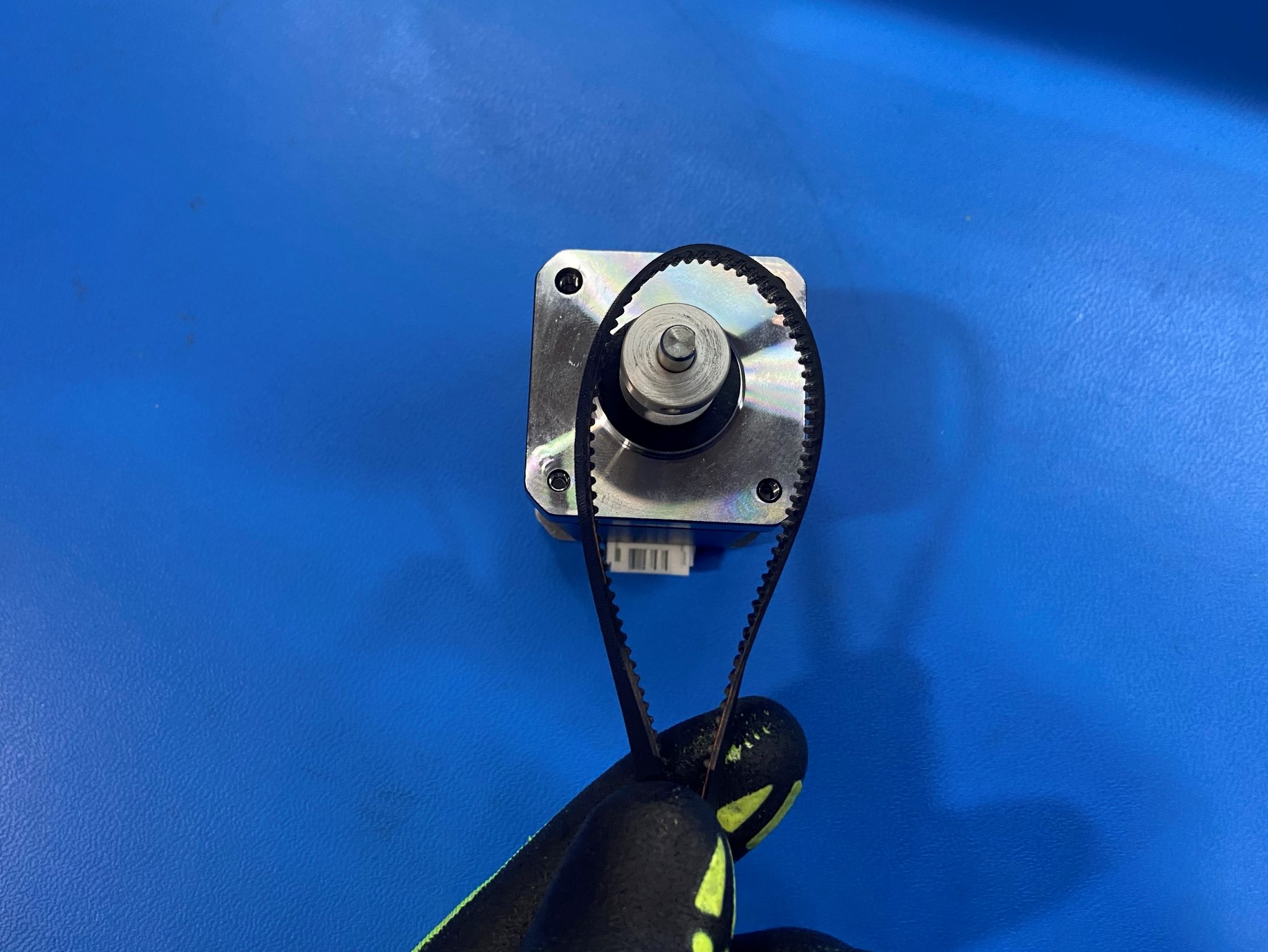
Place the NEMA 17 stepper motor [EL-MT0068] inside the Y motor jig making sure the flat side of the shaft is facing the left then slide 1x 16 teeth timing pulley [HD-MS0033] over the shaft aligning one set screw with the flat side of the shaft and the thicker side of the pulley facing up.
Then torque the pulley to 3in*lbs and remove the motor from the Y motor jig.
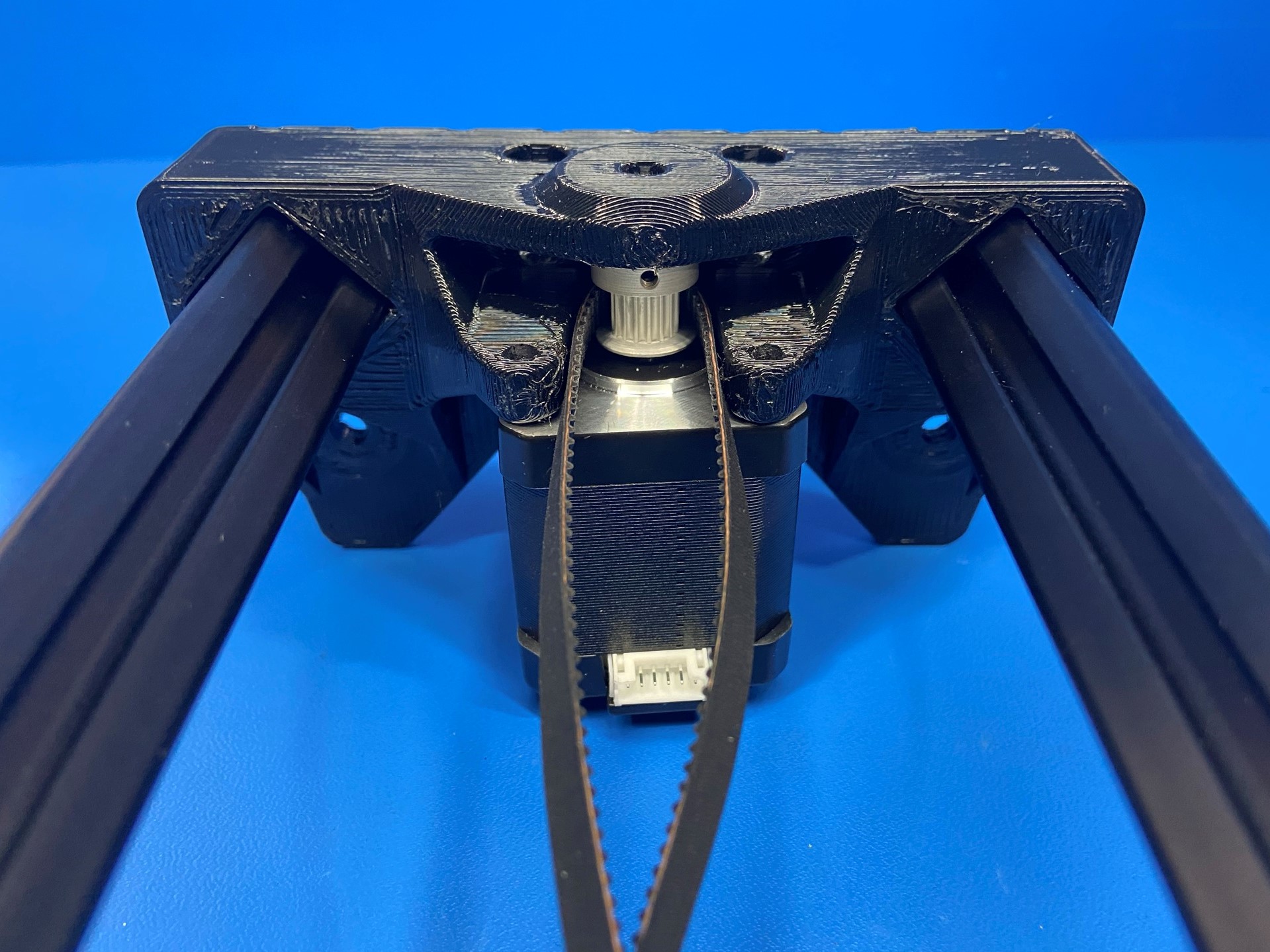
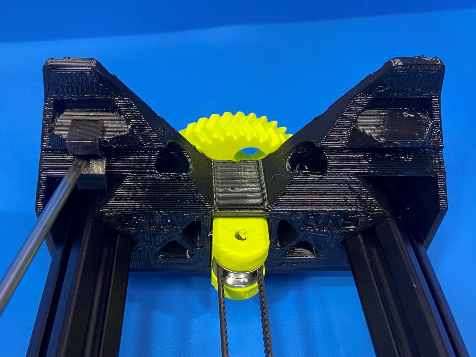
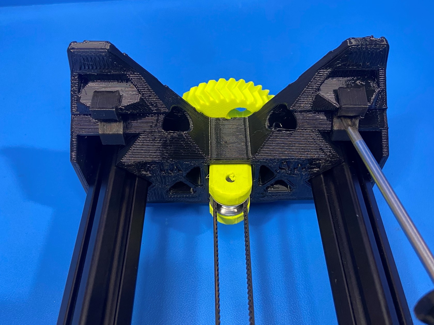
Using the bearing jig place 1x rubber sealed bearing [HD-MS0411] inside the cavity on the Y motor mount.
Take the single sided neoprene belt [HD-BL0032] and loop it around the timing pulley attached to the motor shaft making sure the teeth on the belt align with the teeth on the pulley.
Then slide the motor shaft into the bearing making sure the motor connector is facing toward the Y carriage. Then use 4x M3x12 SHCS [HD-BT0039] and 4x M3 washers [HD-WA0038] to secure the motor to the Y motor mount.
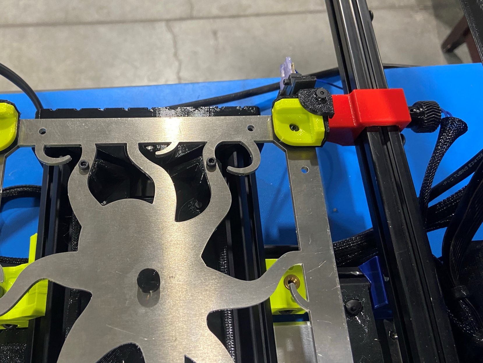
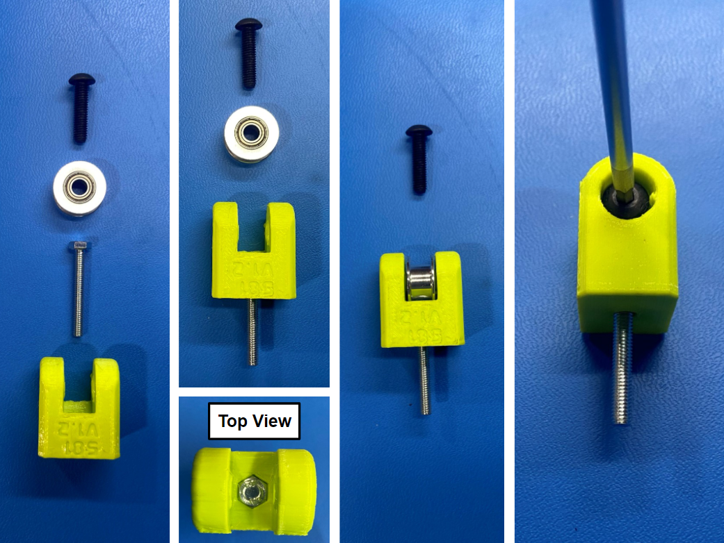
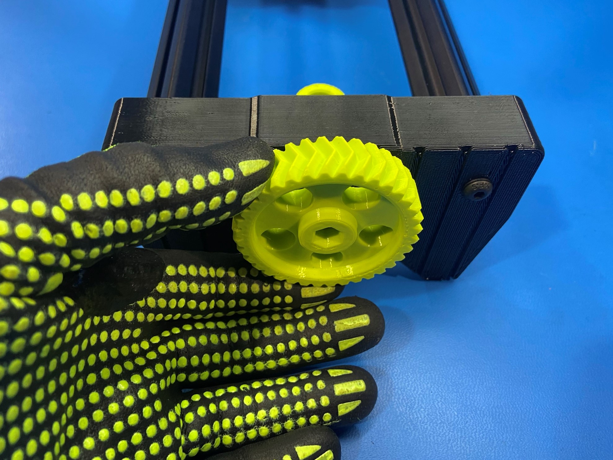
Assemble the XY belt tensioner assembly by taking 1x M4x30 HHCS [HD-BT0266] and push it through the XY belt tensioner [PP-GP0581] making sure its seated inside the hex hole. Then take 1x M5x20 BHCS [HD-BT0272] and secure the 5mm smooth bore idler in between the walls on the XY belt tensioner. [reference#1]
Then slide the XY belt tensioner inside the cavity on the Y idler making sure the head of the screw is facing up.
Then place 1x M5 washer [HD-WA0040] around the tail of the screw and twist the XYZ tensioner knob onto the screw to secure the belt tensioner.
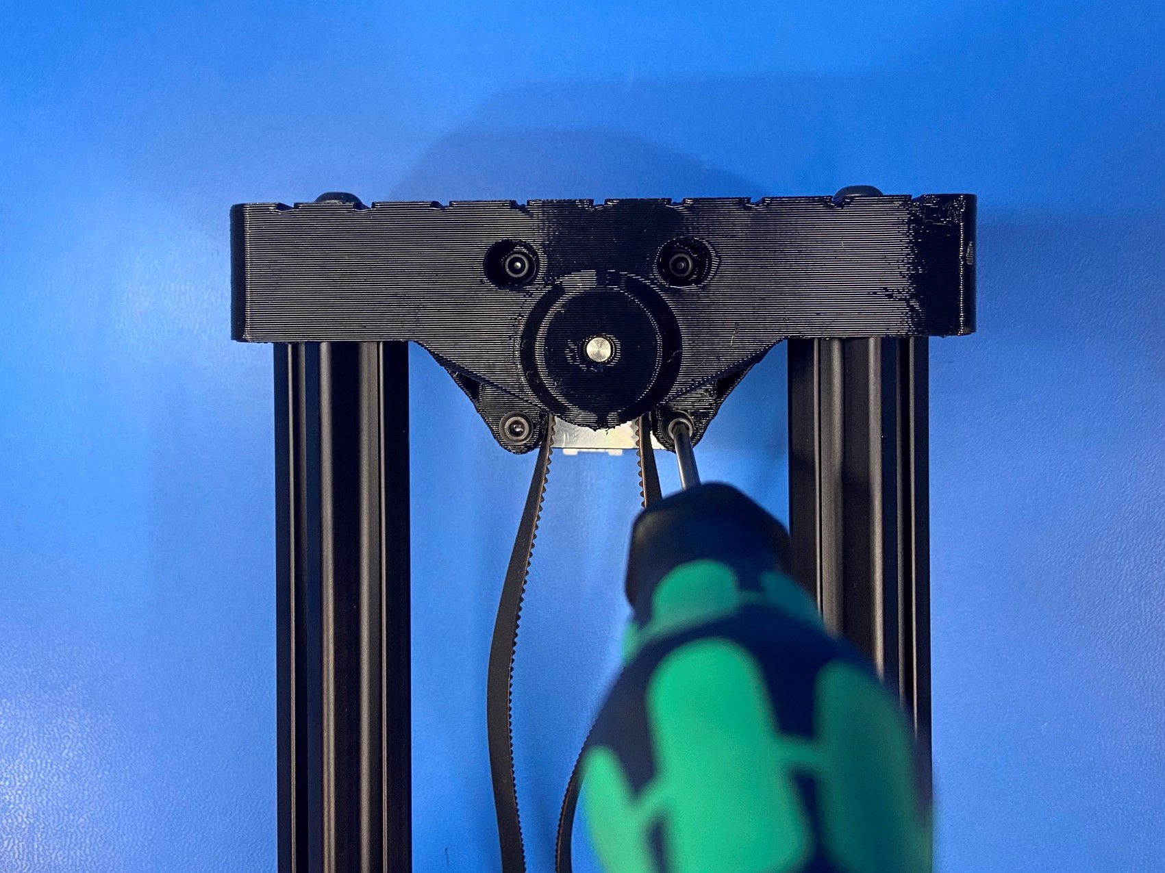

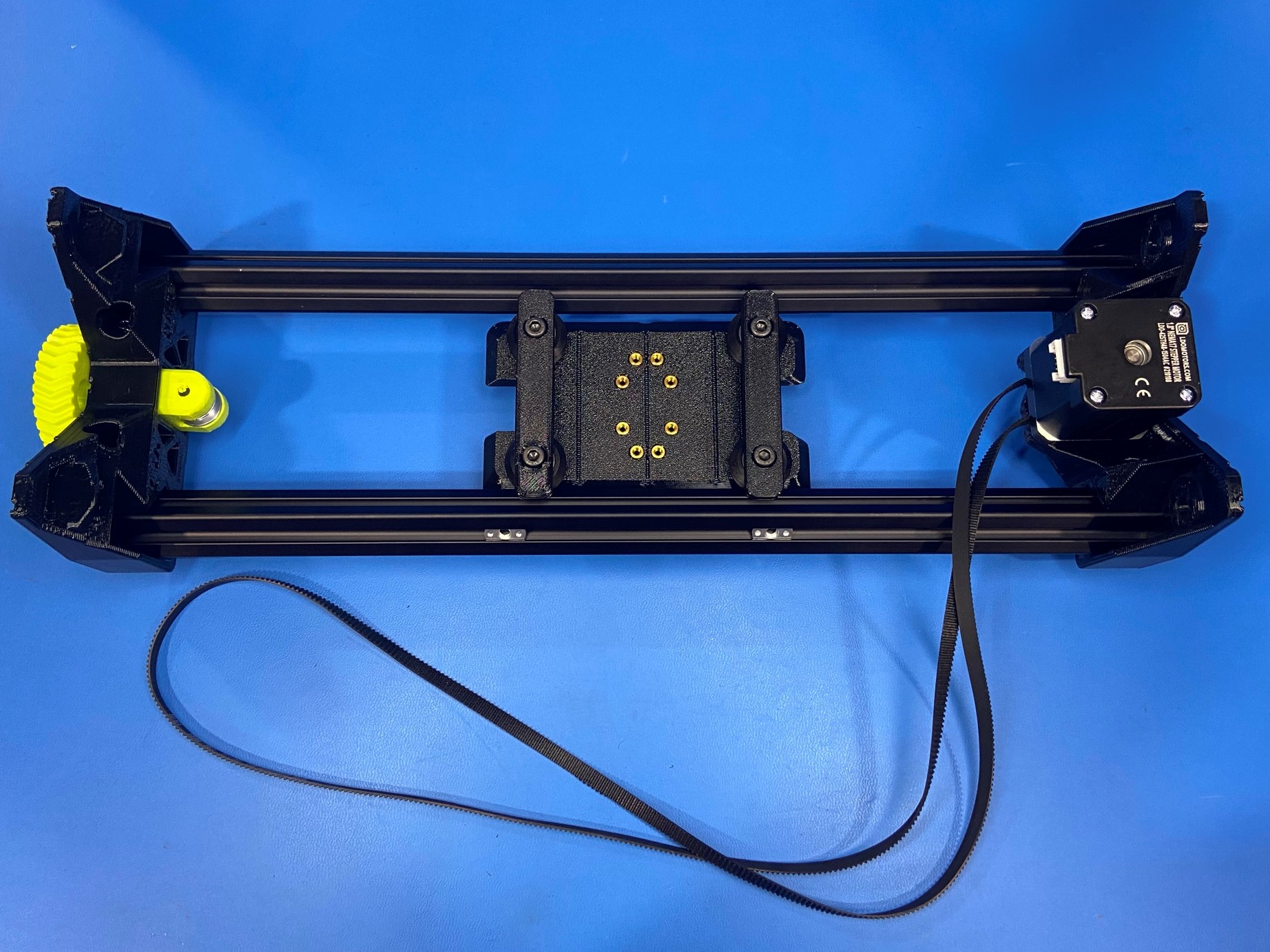
Flip the Y axis over so that you can access the back side of the Y carriage, then route the belt under both V-wheel supports.
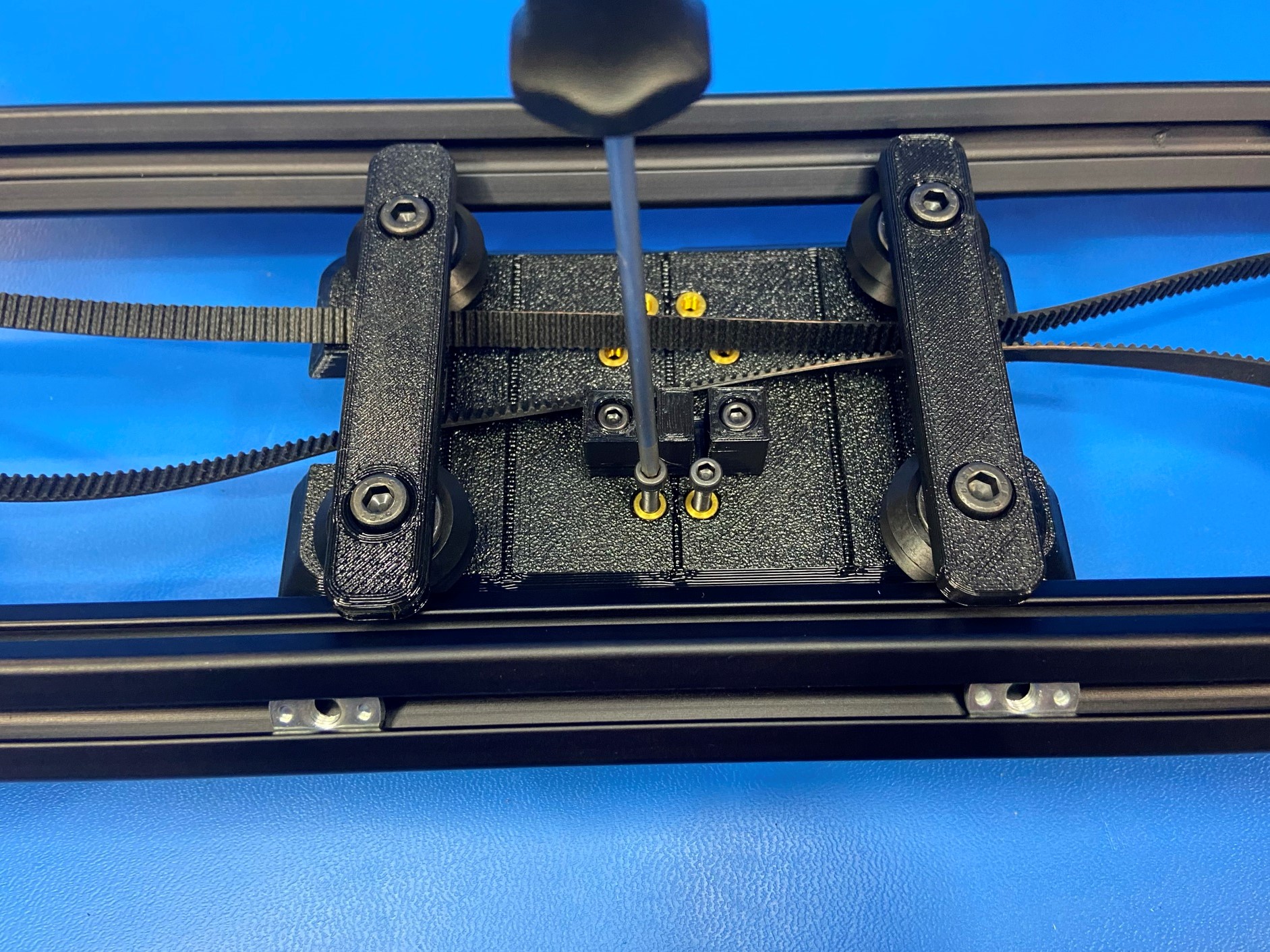
Now using 2x M3x12 SHCS [HD-BT0039] attach the Y belt mount [PP-GP0546] to the Y carriage use the brass inserts that are on the same side as the two T-slot nuts.
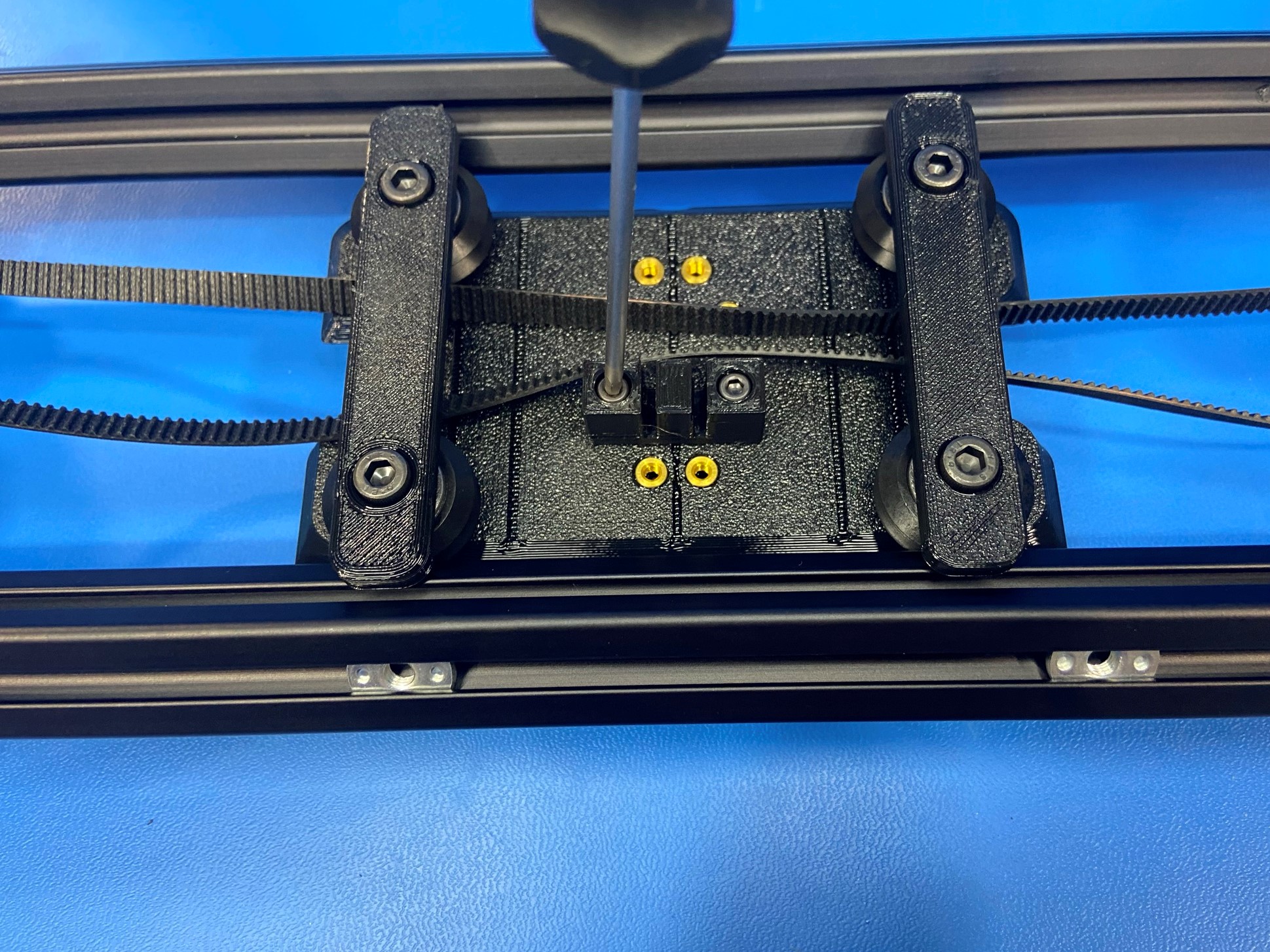
Then fasten 2x M3x20 SHCS [HD-BT0007] to the Y carriage making sure to use the two brass inserts that are on the same side as the T-slot nuts. Tighten them until they are flush with the top of the Y belt clamp.
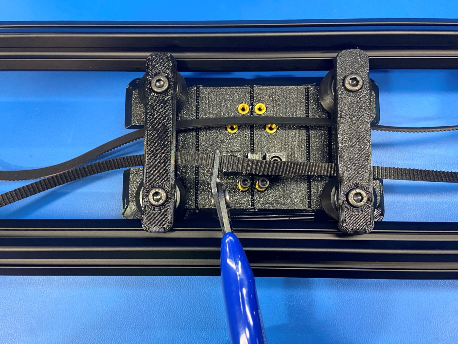
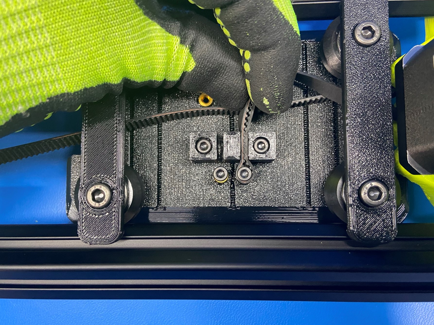
Cut the belt on the side that is next to the Y belt clamp, then take the end of the belt and pitch the teeth together so that there is a loop. Make sure not to leave a long tail
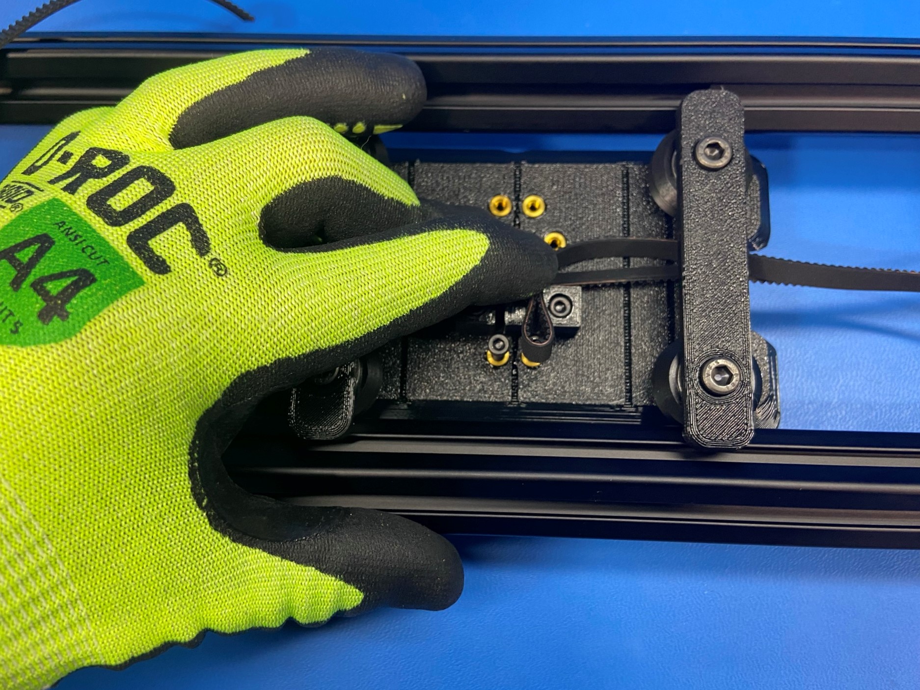
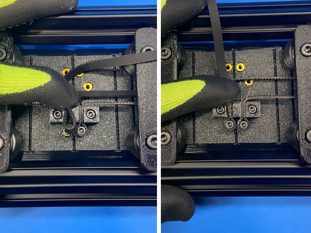
Then take the pitch part of the belt and slide it in the gap on the Y belt mount making sure the loop in close to the [HD-BT0007] bolt head.
Now slide the loop over the bolt head and around the bolt, and pull on the tail of the belt to secure it to the Y carriage. Make sure to push the belt down as far as you can to secure this connection
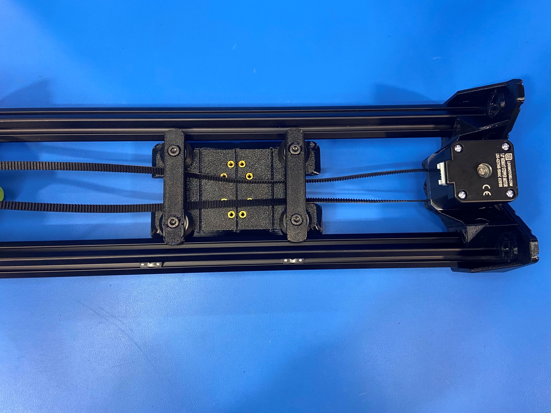
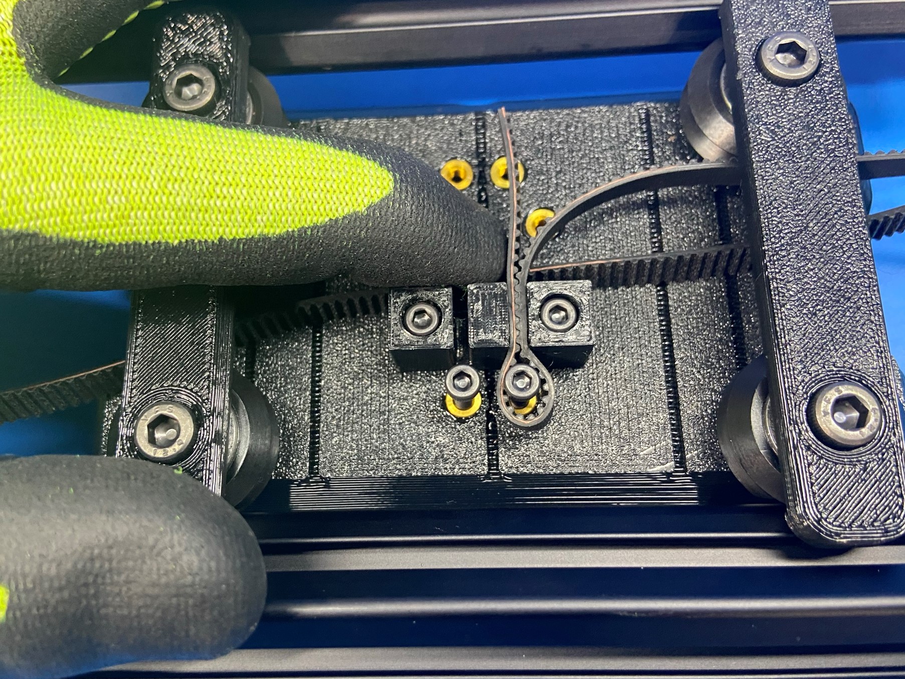
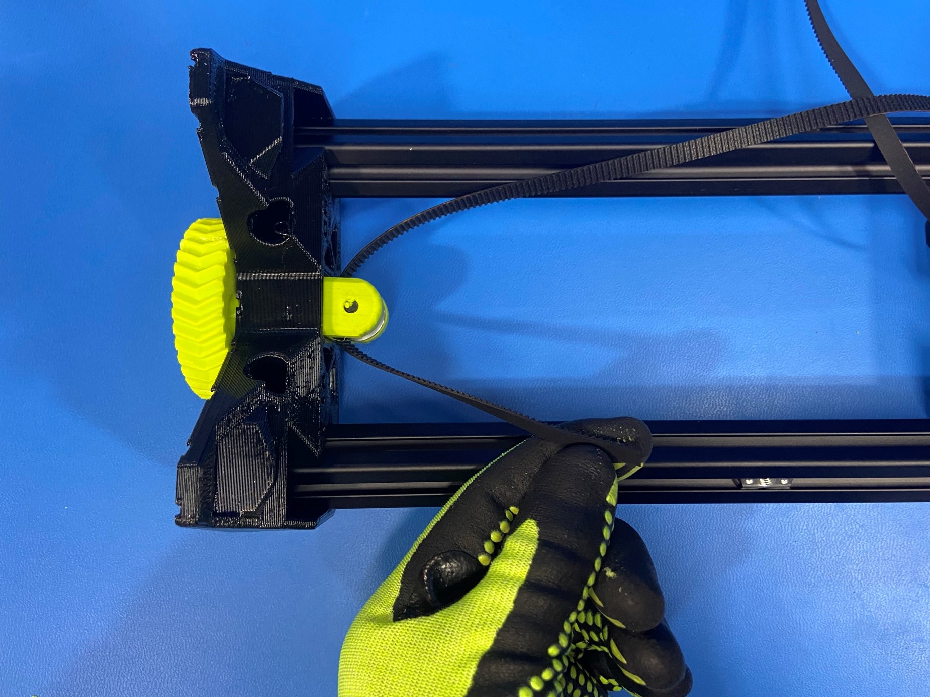
Take the other end of the belt and route it around the smooth idler on the XY belt tensioner, making sure there is no twist in the belt.
Then route it under the V-wheel supports on the Y carriage and repeat the process for securing the belt to the carriage, only this time pull the belt tight then start the process.
Note: If there is too much slack in the belt you won't be able to tension correctly.
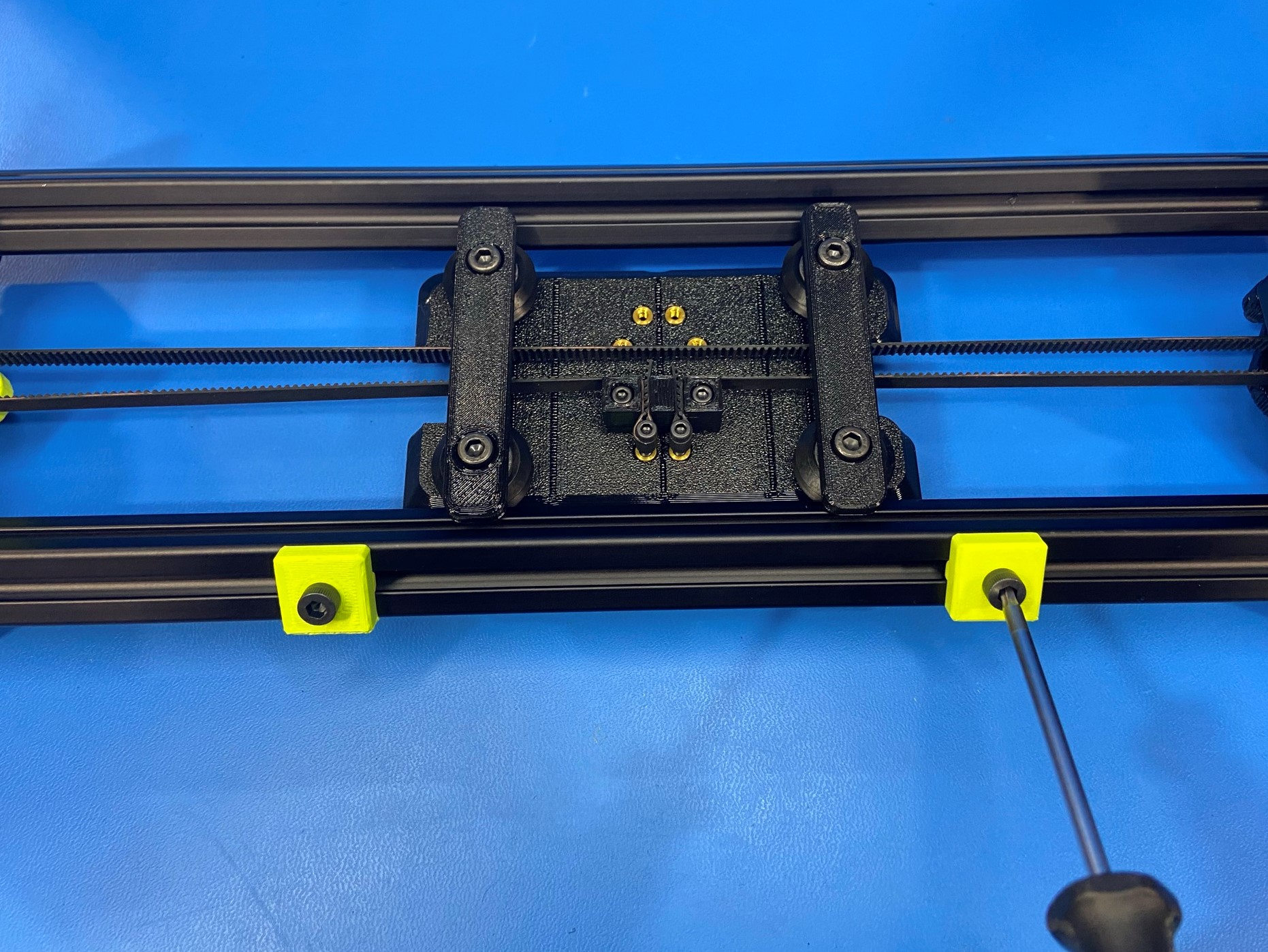
Once both ends of the belt are connected to the Y carriage trim the ends of the belt so that they can't reach the other side.


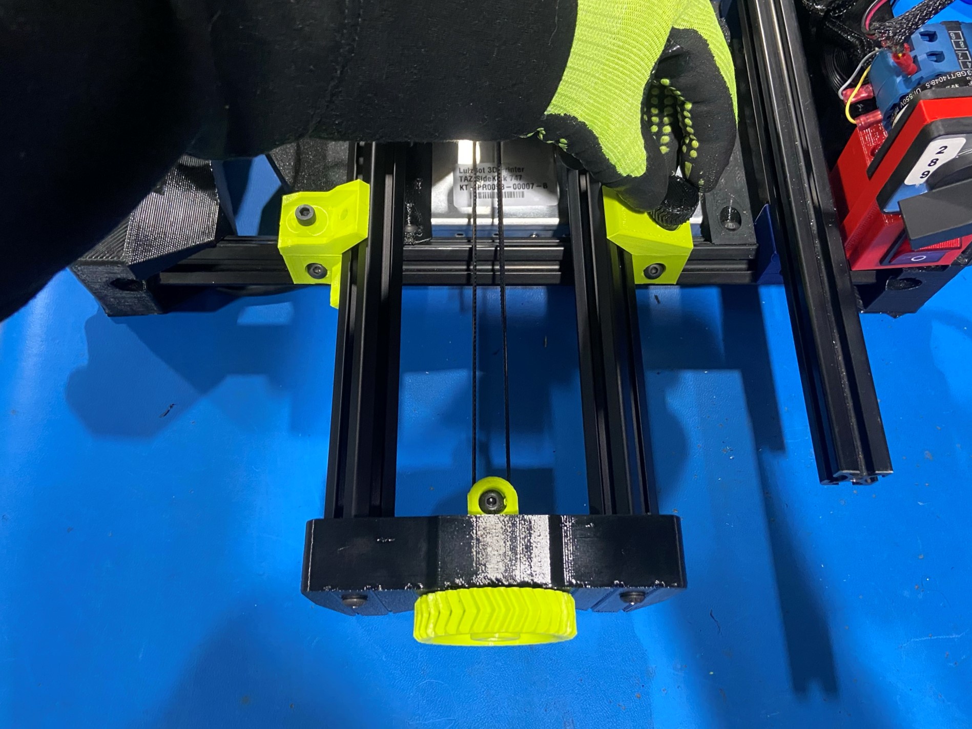
Using 1x M5x12 SHCS [HD-BT0263] fasten the Y axis placement block [PP-GP0692] to one of the T-slot nuts, then repeat for the second T-slot nut.
Note: You can leave these loose because they will be moved later on.
Then push 2x flexy cushion Y idler [PP-GP0644] into the Y idler, push them inside the two rectangular holes on both sides of the Y idler.
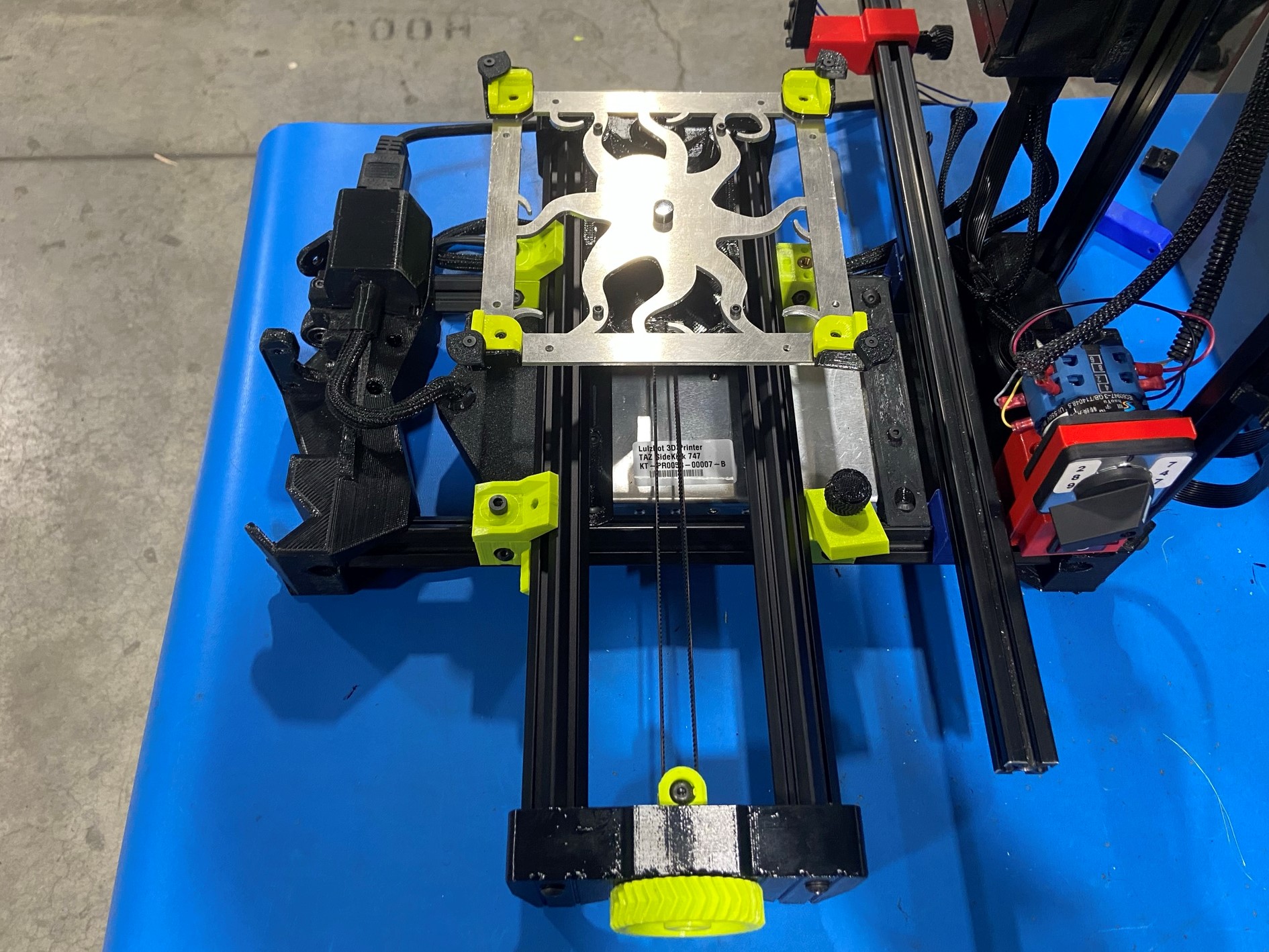
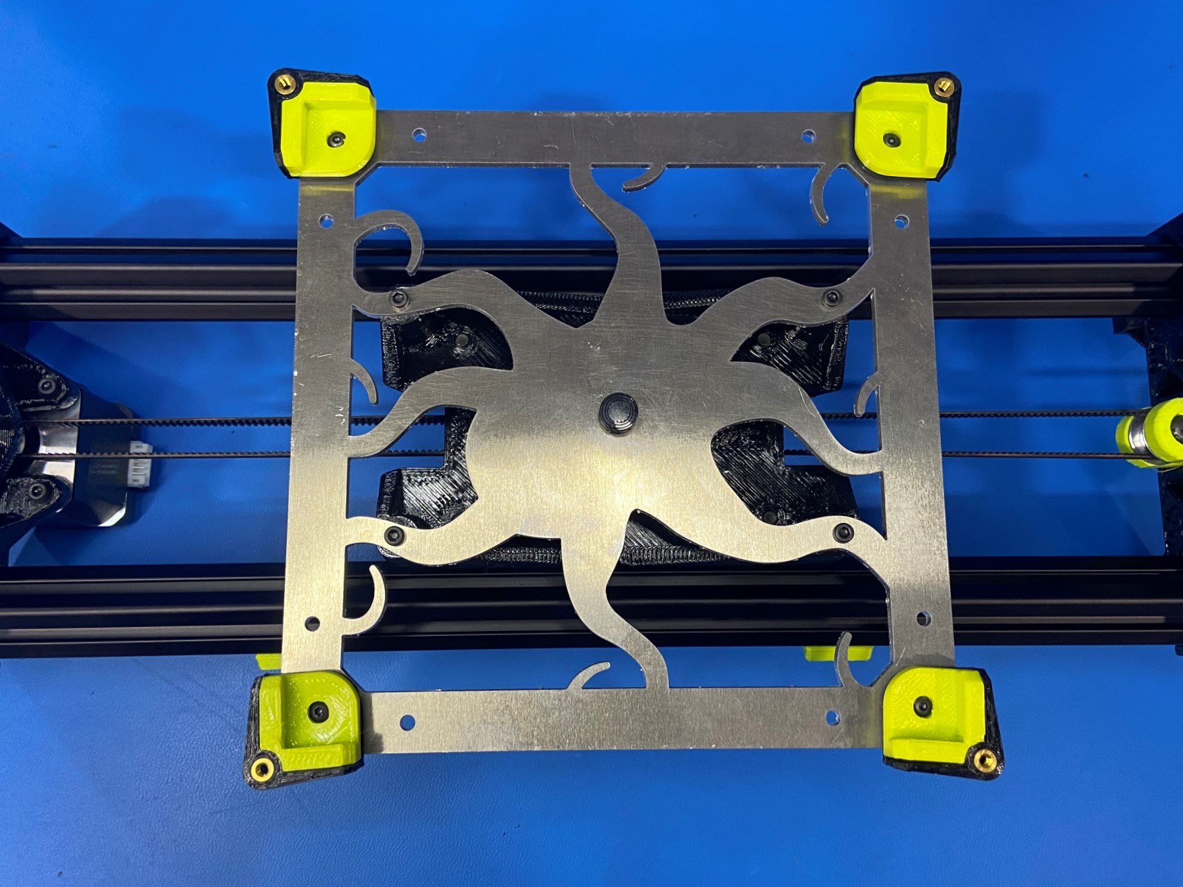
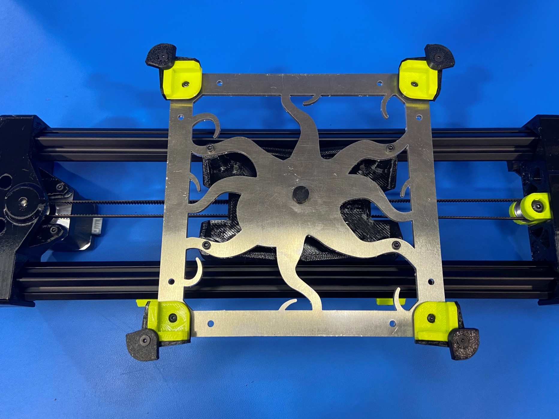
Now flip the Y axis over so that the top side of the Y carriage is facing up, and place the SK octoluminum bed plate 289 [PP-FP0220] over the Y carriage.
Note: Make sure the smooth side of the bed plate is facing up and the head of the octopus is pointing towards the Y motor mount
Use 4x M3x10 SHCS [HD-BT0005] to attach the bed plate to the Y carriage.
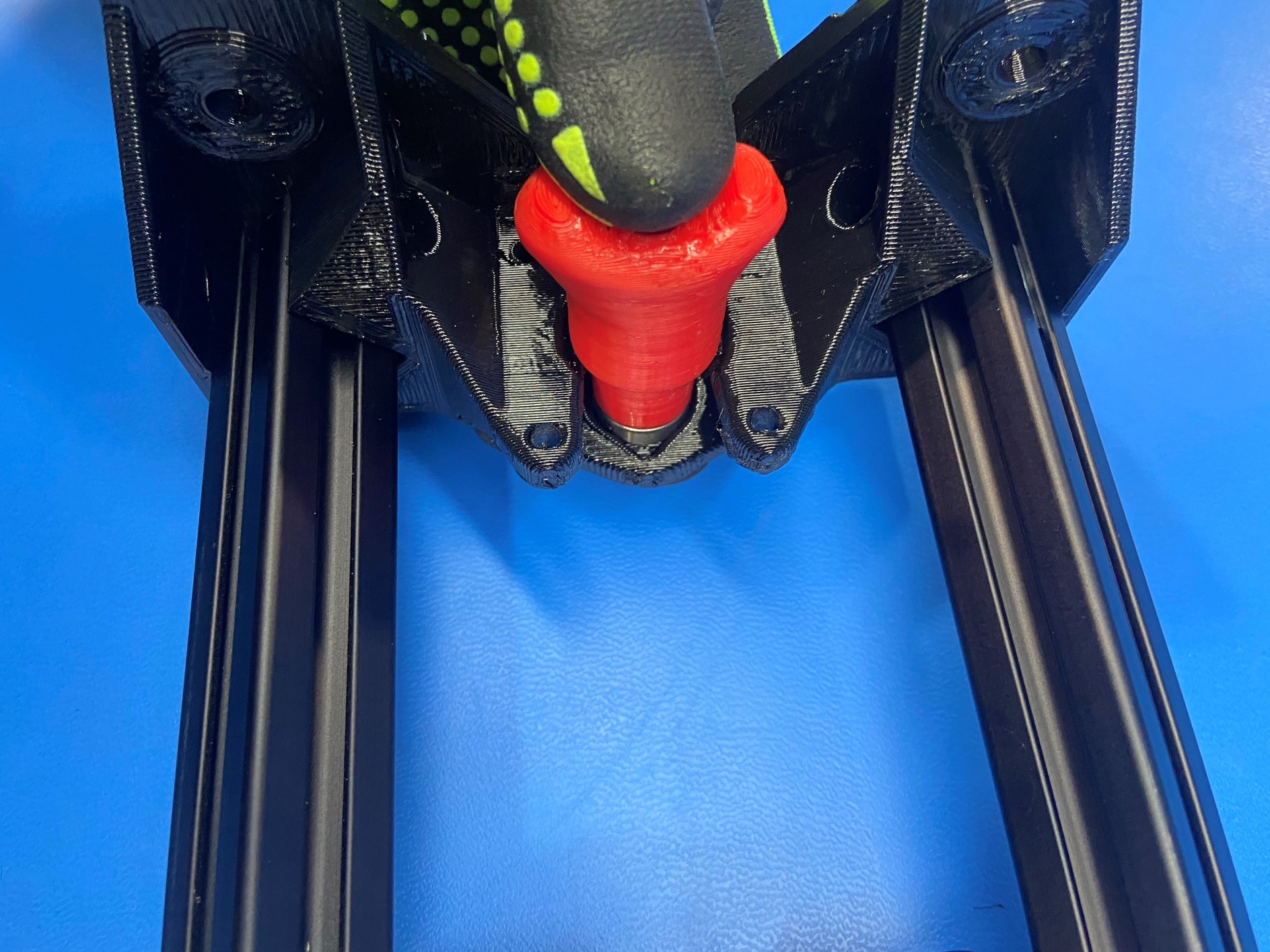
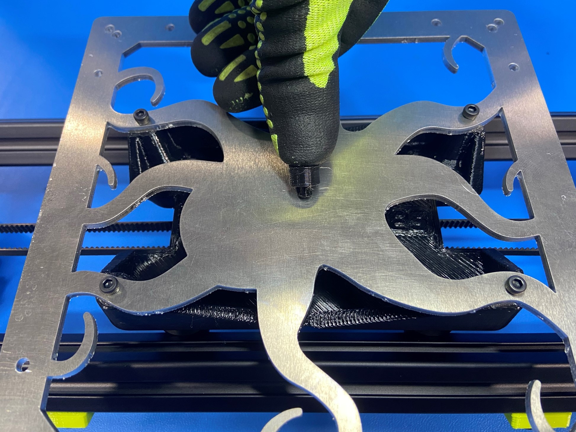
Push the bed center post [PP-GP0634] into the center hole on the bed plate.
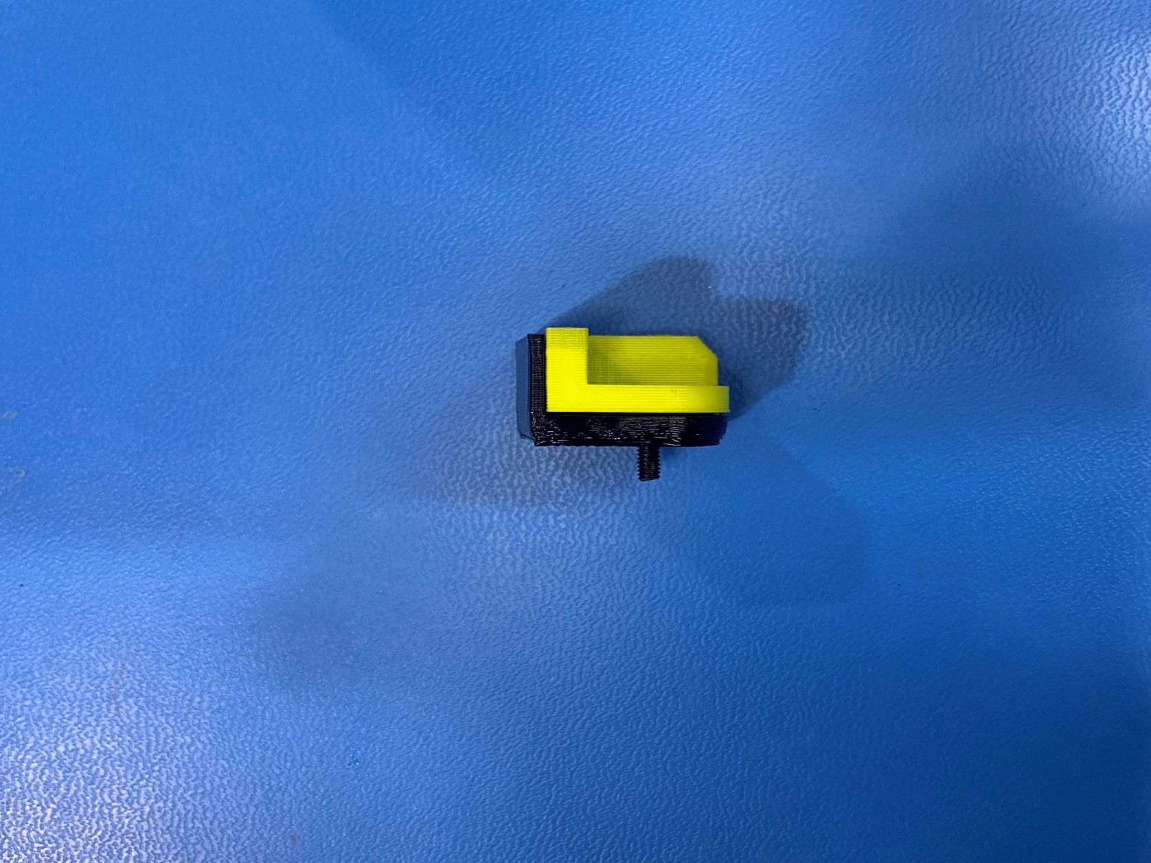
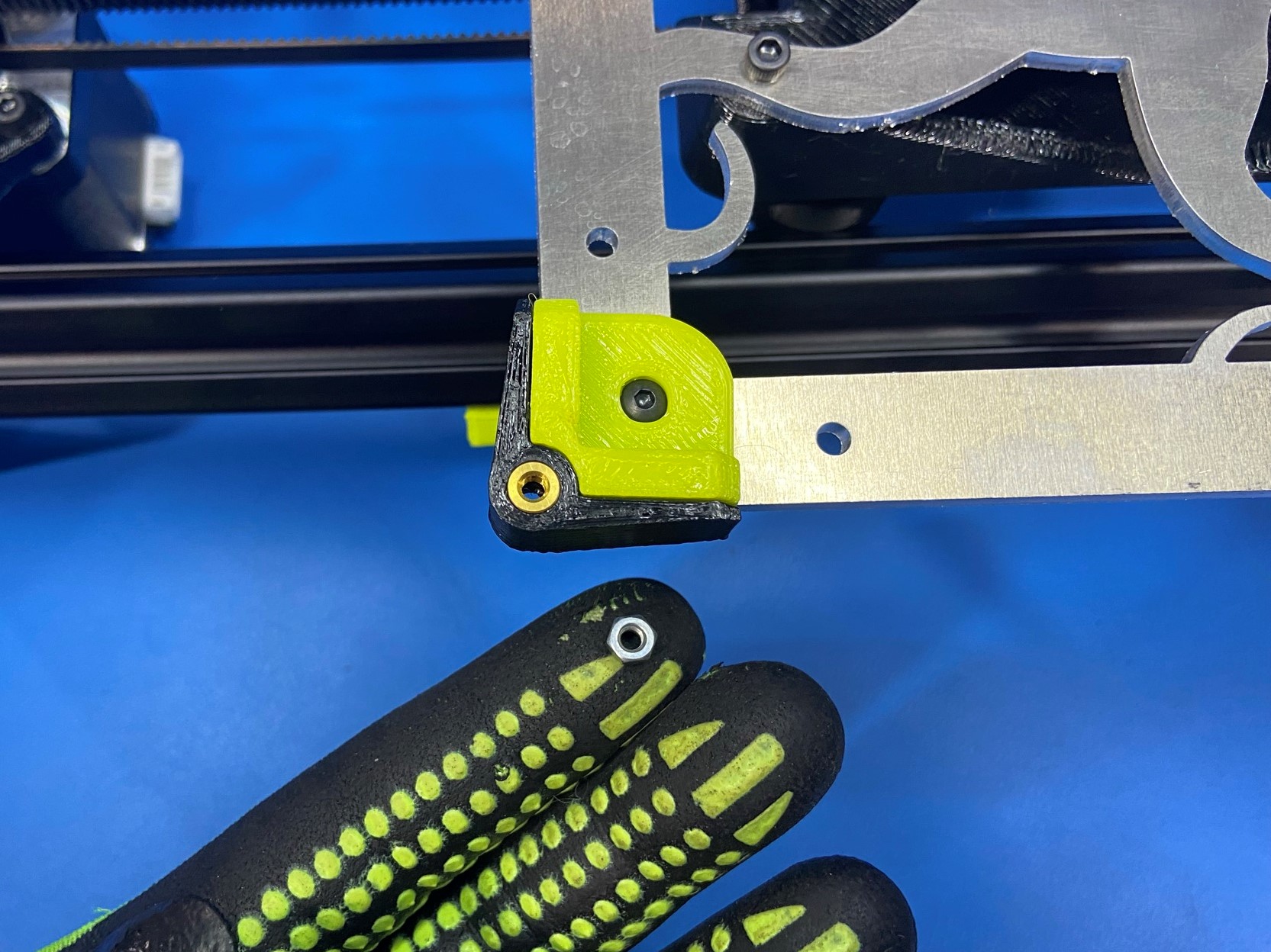
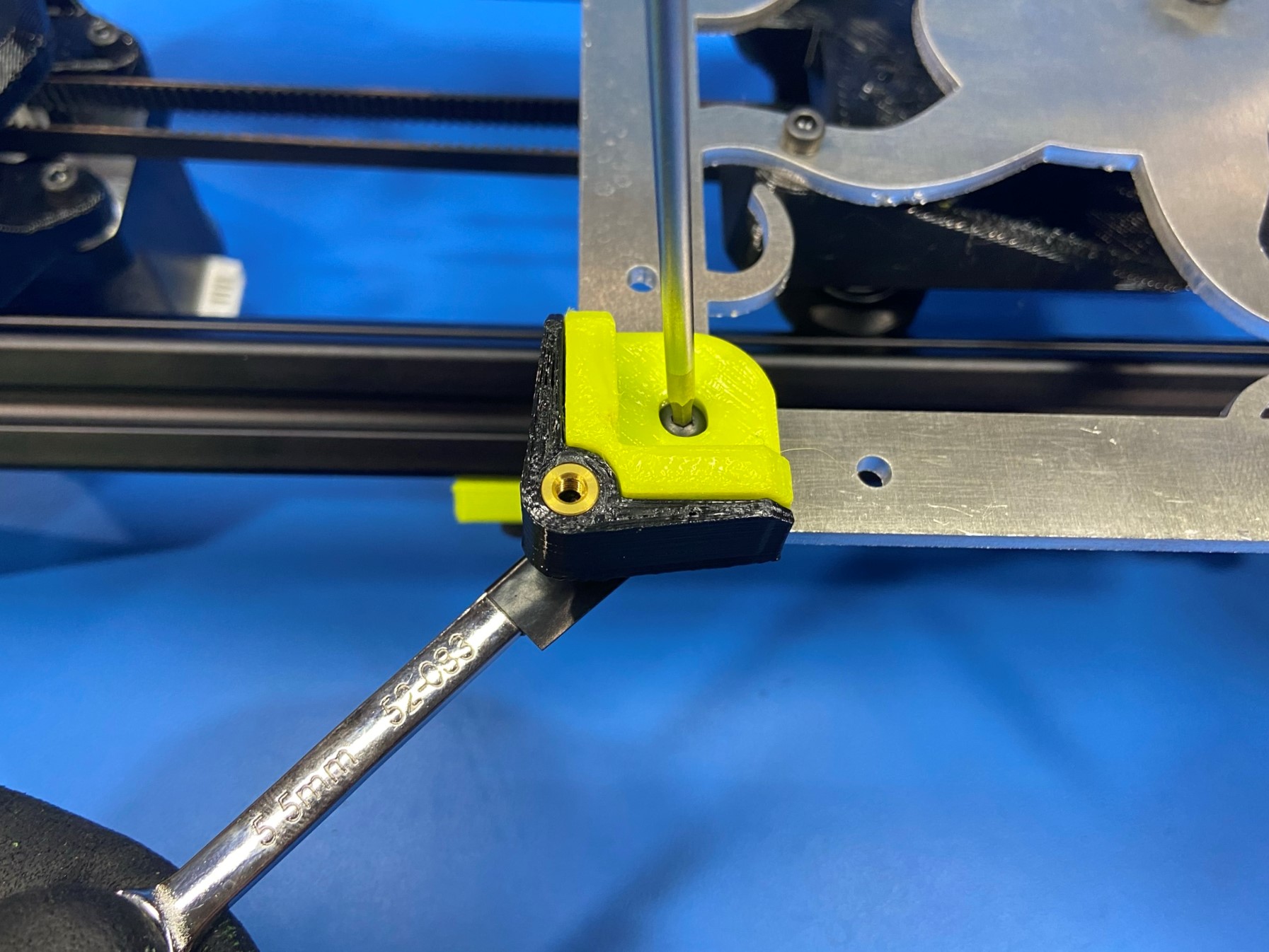
Then take 1x flexy bed corner [PP-GP0533] and set it inside the bed corner base [PP-GP0652] and push 1x M3x10 BHCS [HD-BT0148] through both pieces as shown in [reference#2]
Slide the tail of the bolt through the edge hole that is closest to the center of the build plate and use 1x M3 nut [HD-NT0001] to secure the bed corner.
Note: If you over tighten the bolt, it may pull through the flexy bed corner
Repeat for the other three corners.
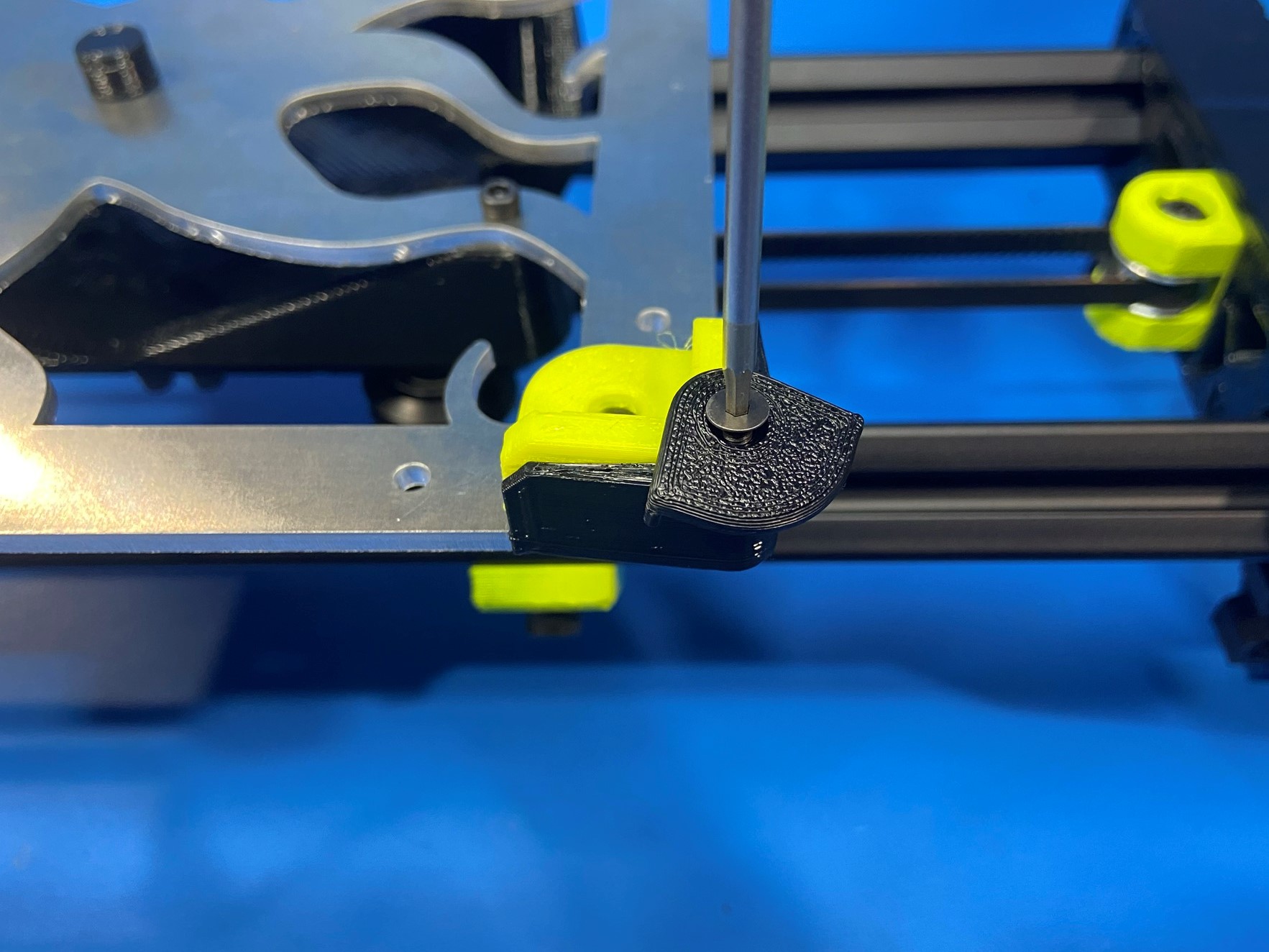
Once all four bed corners are attached to the build plate use 4x M3x8 FHCS [HD-BT0130] and attach a bed corner cover [PP-GP0651] to each bed corner.

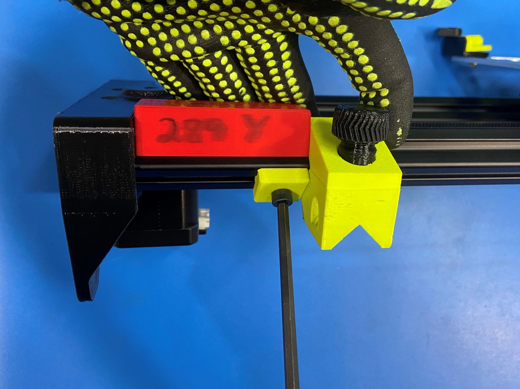
Use the red 289 Y jig along with the green Y axis frame mount jig to set the correct distance from the Y motor mount to the Y placement block.
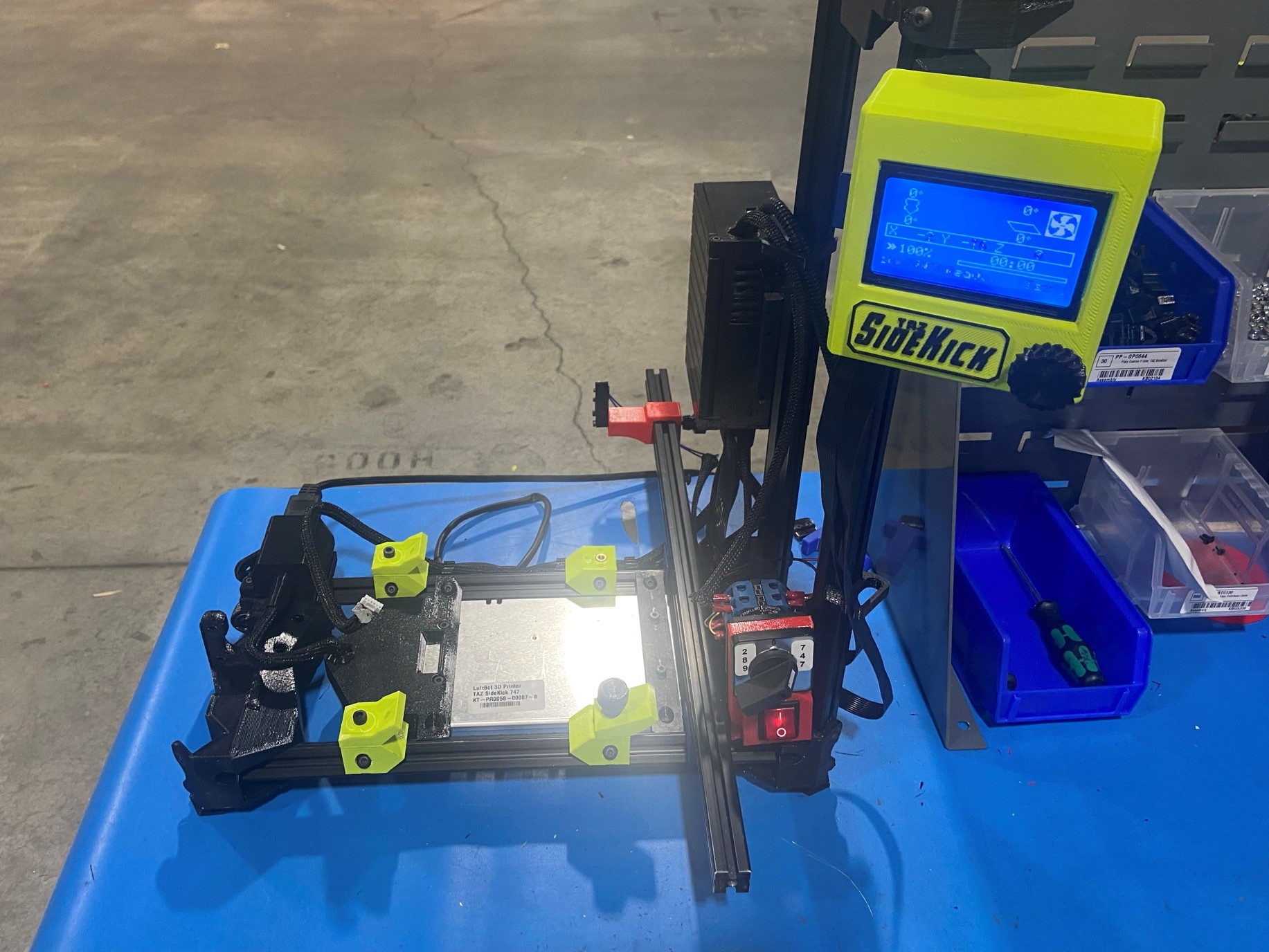
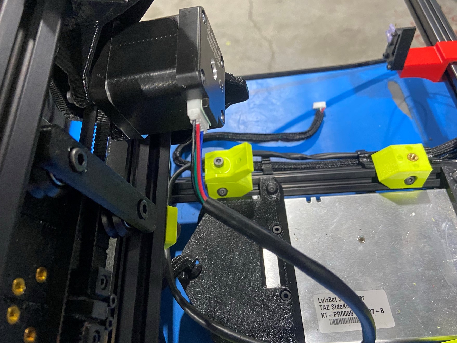
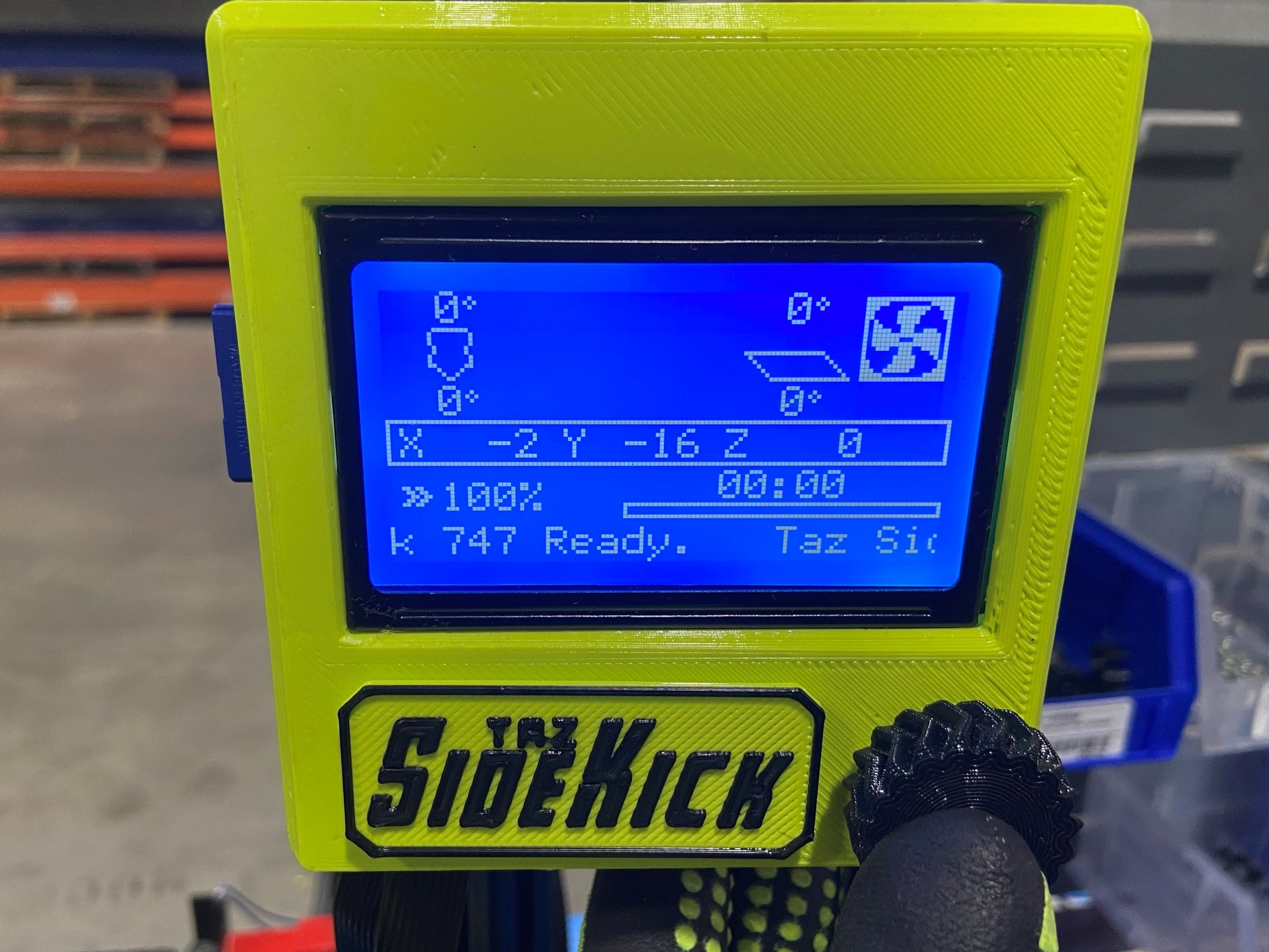
Then bring the Y axis to the test printer and connect the motor to the printer.
Now place the Y axis in-between the brackets on the printer and tighten the front right bracket to secure the Y axis.
Slide the Y axis towards you until the rear Y placement block hits the test printer's bracket.
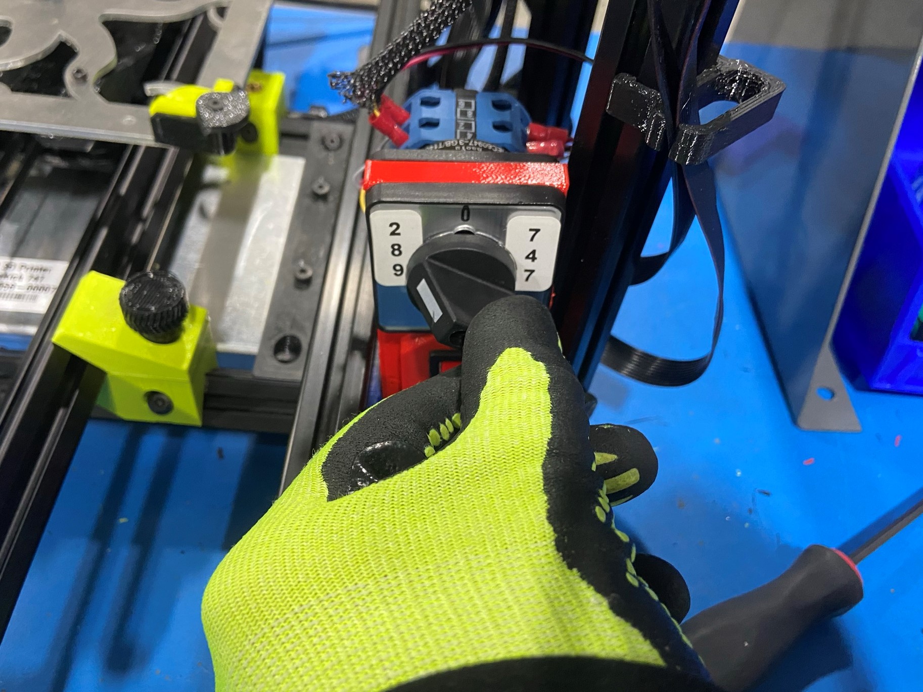
Then make sure the printer's front switch is set to 289 and the rear limit switch is in the front or closest position.
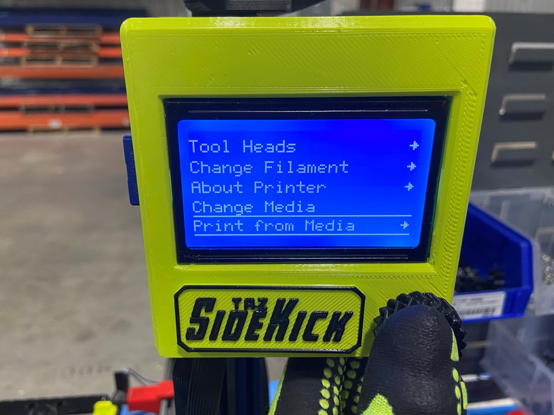
Now turn the printer on and press the knob to get to the options page, then scroll all the way down till you see "Print from Media" then press the knob.
You should see two gcodes one for the 289 and one for the 747, select the 289 and select print.
Watch the bed plate and make sure it hits the back switch, it will slowly hit the switch a couple time to calibrate the distance.
Once the test is finished you can remove the Y axis and you are finished with the assembly.