Open HardwareAssembly Instructions
Guides for installation and assembly of the LulzBot line of products made by FAME 3D LLC.
Guides for installation and assembly of the LulzBot line of products made by FAME 3D LLC.
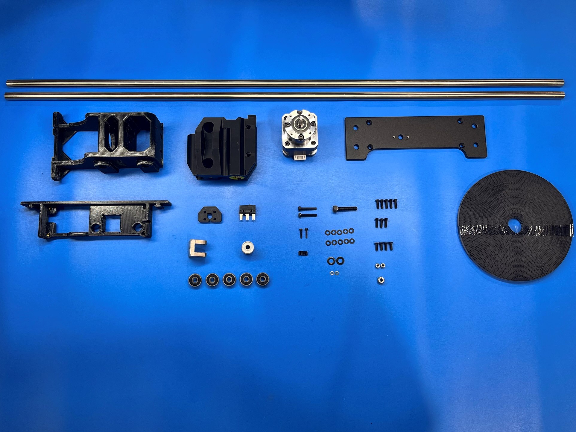
1x- [EL-MT0084] LDO Gear Ratio Motor 5:1
1x- [EL-SW0022] Switch Basic 3A 125V
1x- [HD-BL0037] 6mm Wide Belt 1600 mm
4x- [HD-BT0012] M3x6 Set Screw
2x- [HD-BT0107] M2x10 SHCS, Black-Oxide
4x- [HD-BT0116] M3x10 FHCS, Black-Oxide
8x- [HD-BT0148] M3x10 BHCS, Black-Oxide
1x- [HD-BT0151] M5x20 SCHS, Black Oxide
1x- [HD-BT0158] M5x12 BHCS, Black-Oxide
2x- [HD-BT0185] M3x16 SHCS, Black-Oxide
1x- [HD-BT0196] M5x25 SHCS, Black-Oxide
1x- [HD-MS0033] GT2, 16 Teeth, timing pulley
5x- [HD-MS0411] Premium Two Side Rubber Sealed Bearing
2x- [HD-NT0001] M3 Locknut
1x- [HD-NT0057] M5 Locknut
2x- [HD-RD0080] 10mm Smooth Rod SST 705mm
2x- [HD-WA0012] M2 Steel Flat Washer
10x- [HD-WA0038] M3 Washer, Black-Oxide
3x- [HD-WA0040] M5 Washer, Black-Oxide
1x- [PP-FP0156] Z Upper Top Plate
1x- [PP-GP0141] X End Idler Pro/WE
1x- [PP-GP0357] Z Upper Right Pro/WE
1x- [PP-GP0689] Z Axis Belt Clamp Pro XT
1x- [PP-GP0698] Z Lower Right Pro/WE
1x- [PP-MP0225] YZ Idler Pro/WE
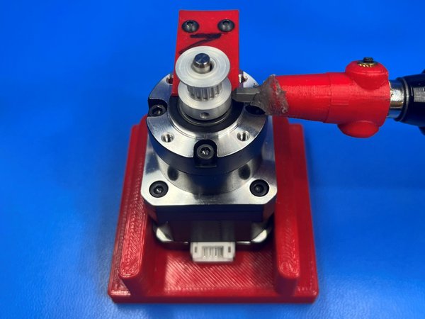
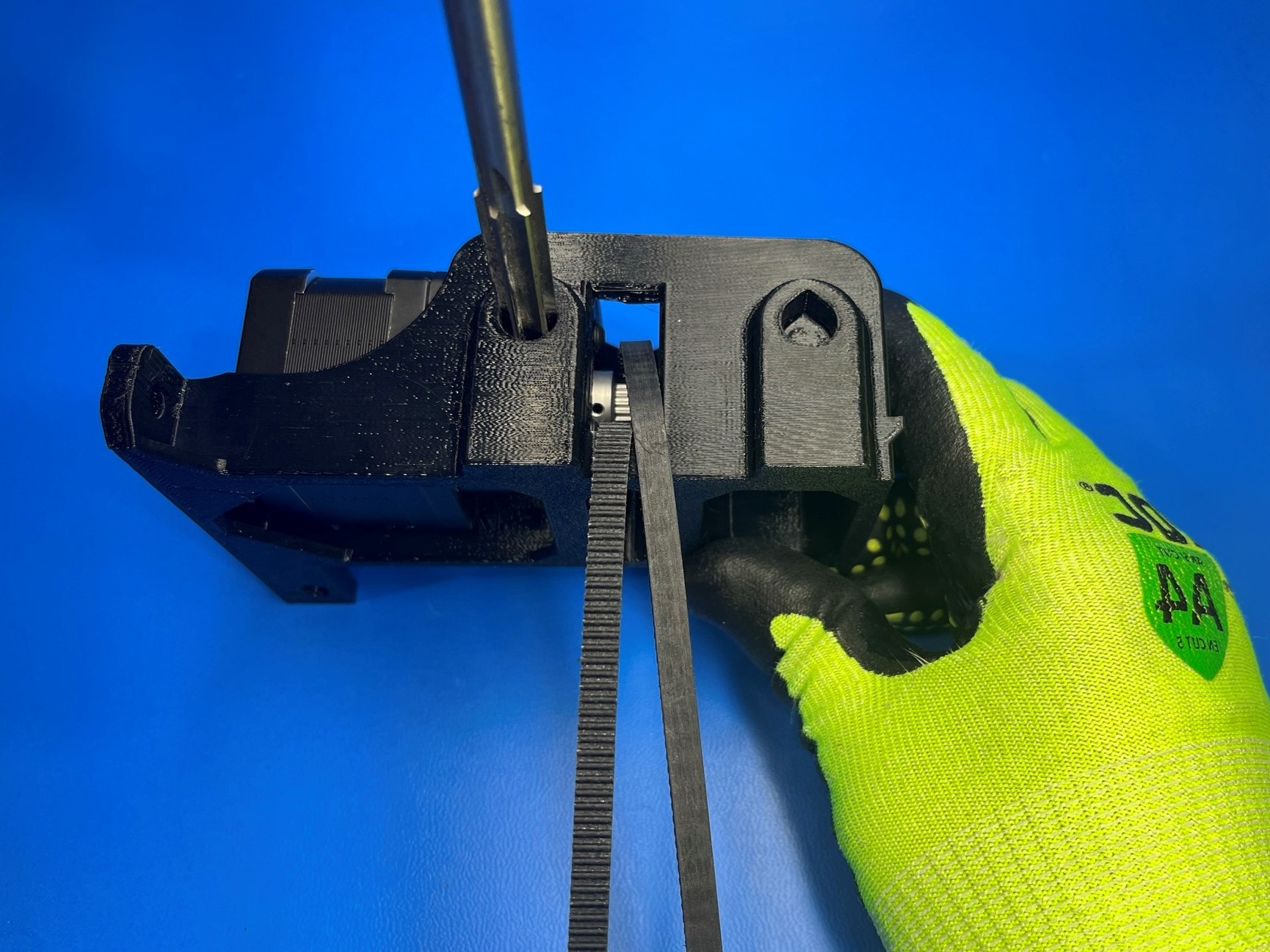
Place 1x LDO geared stepper motor [EL-MT0084] inside the Z lower right motor jig, then slide 1x 16 teeth timing pulley [HD-MS0033] on the motor shaft making sure one of the set screws on the pulley is aligned with the flat side of the motor shaft.
While pushing down on the timing pulley torque the set screws to 3 in*lb.
Using the bearing punch and 1x rubber sealed bearing [HD-MS0411] and Z lower right [PP-GP0698] press the bearing into the Z lower right.
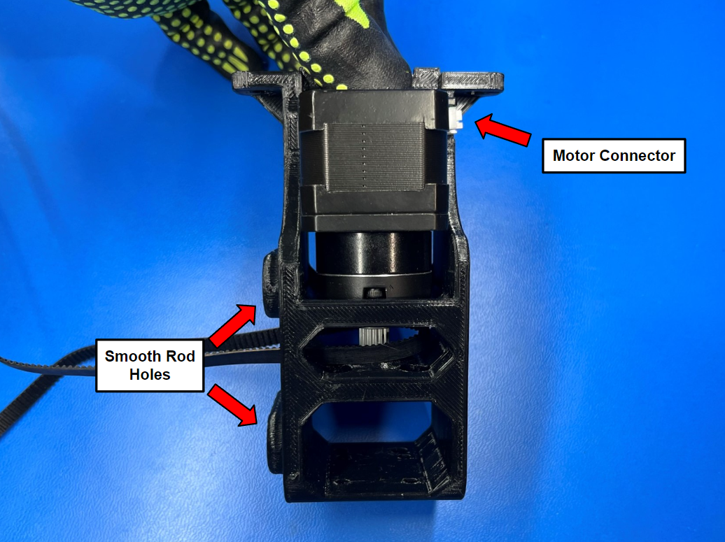
Then align the motor with the Z lower right so that the connector is on the opposite side as the smooth rod holes.
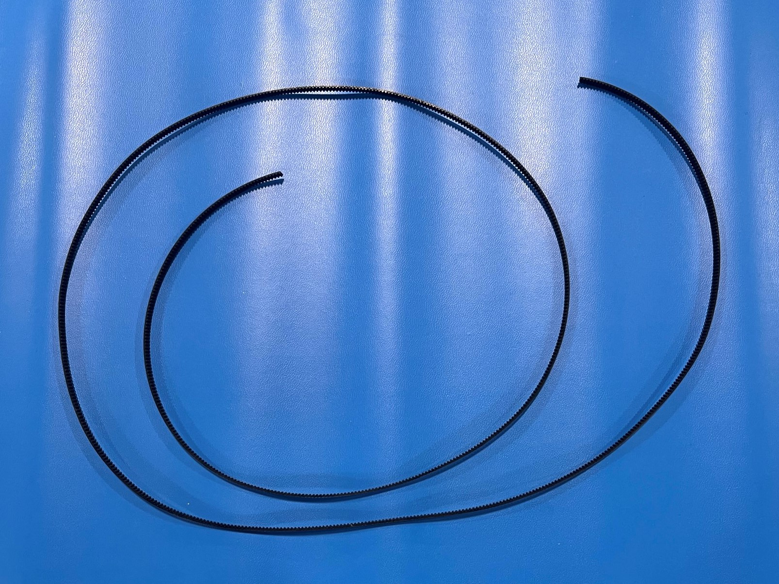
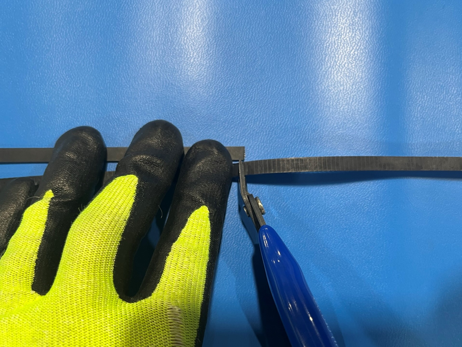
Use the sample belt to cut 1600mm of the 6mm belt [HD-BL0037].
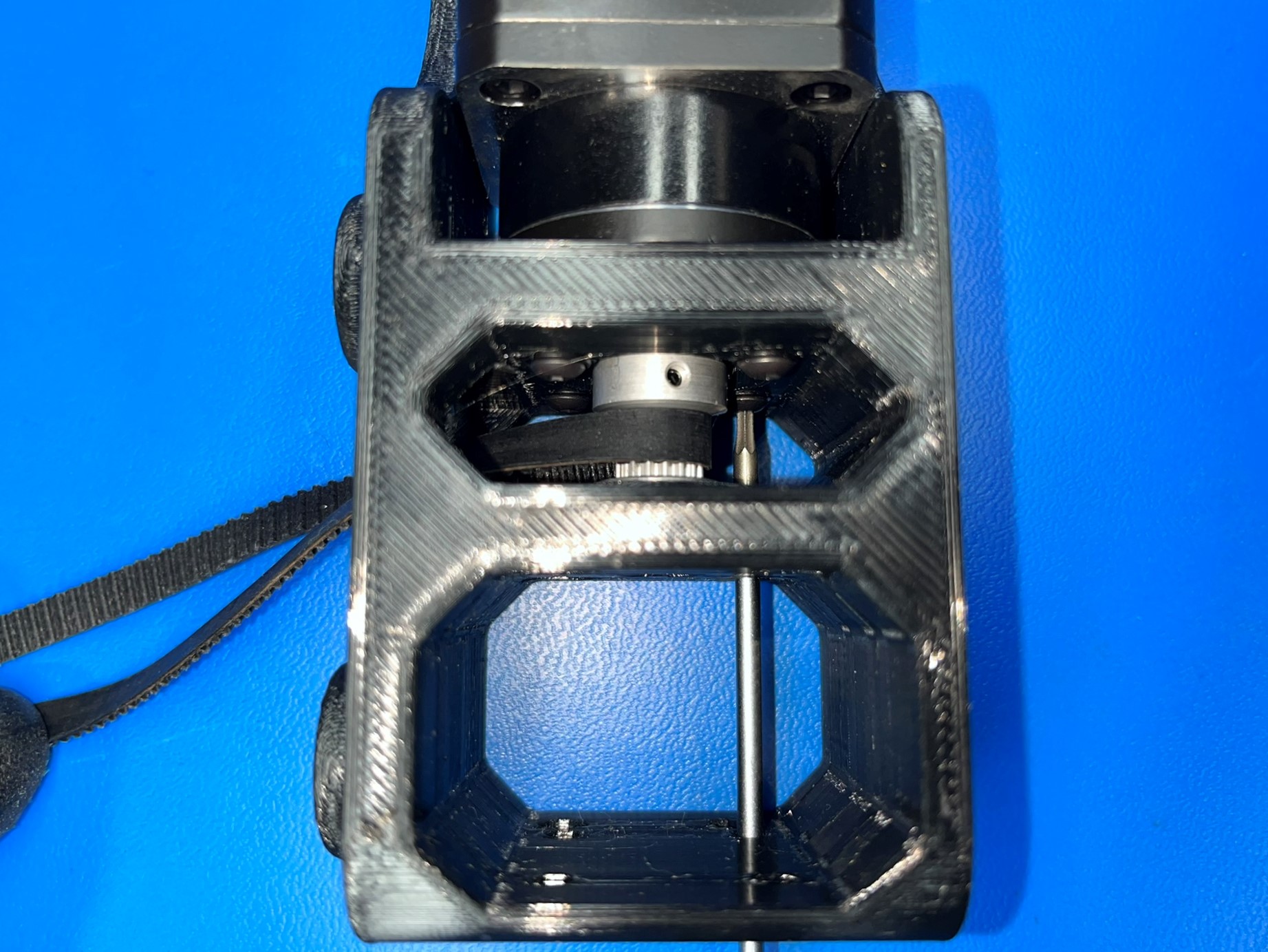
Before fully sliding the motor into the Z lower right, loop and feed the belt through the hole between the two smooth rod holes and loop it around the timing pulley.
Then push the motor so that the shaft goes through the bearing while making sure the connector is on the opposite side of the smooth rod holes.
Once the motor is placed inside the Z lower right secure using 4x M3x10 BHCS [HD-BT0148] with M3 washers [HD-WA0038].
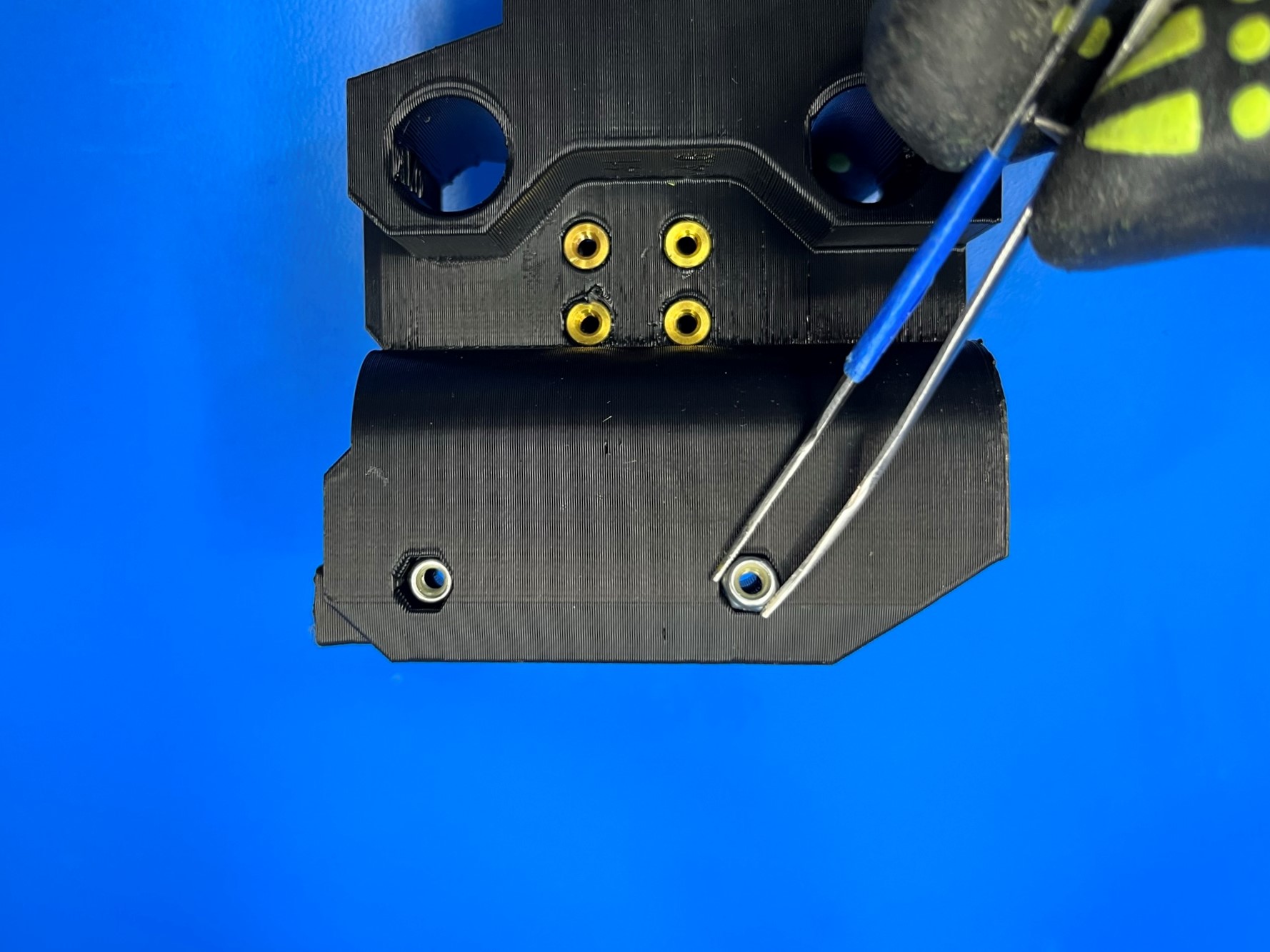
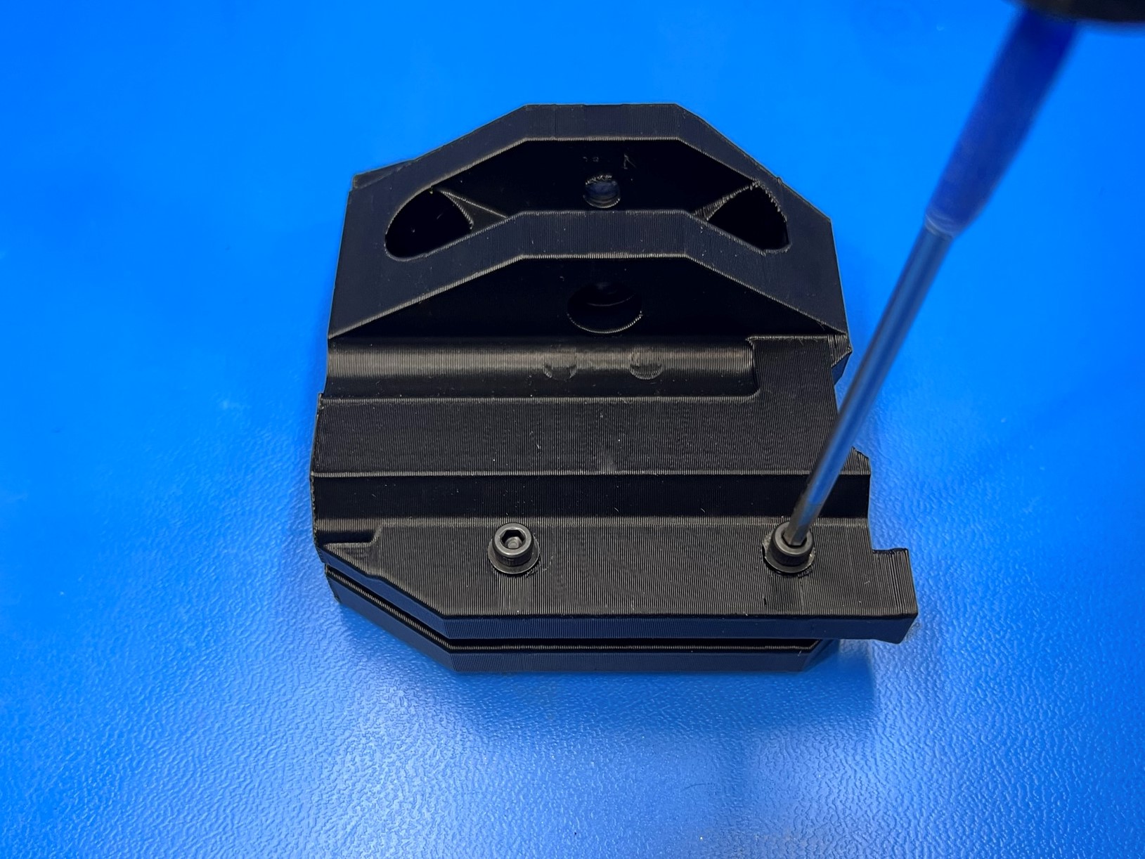
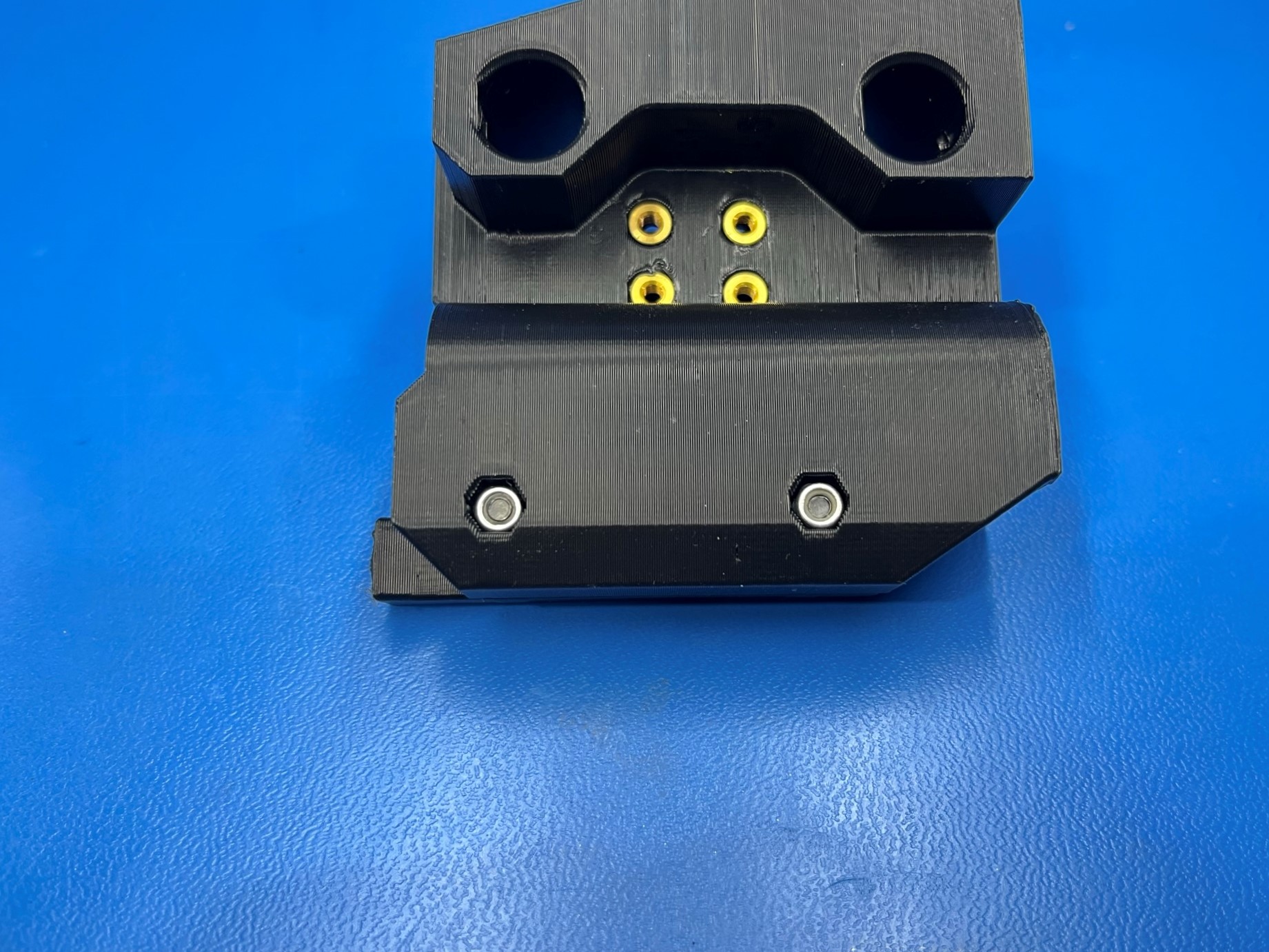
Place 2x M3 lock nuts [HD-NT0001] inside the two nut traps in the X end idler. Then using 2x M3x20 SHCS [HD-BT0007] with washers [HD-WA0038] secure the lock nuts. Make sure to leave screws loose.
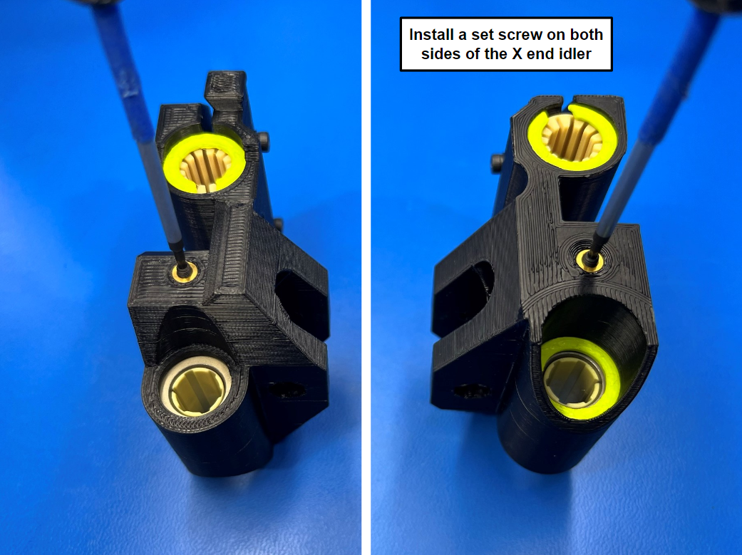
Then thread 2x M3 set screws [HD-BT0012] into the two brass inserts on the left and right side of the X end idler.
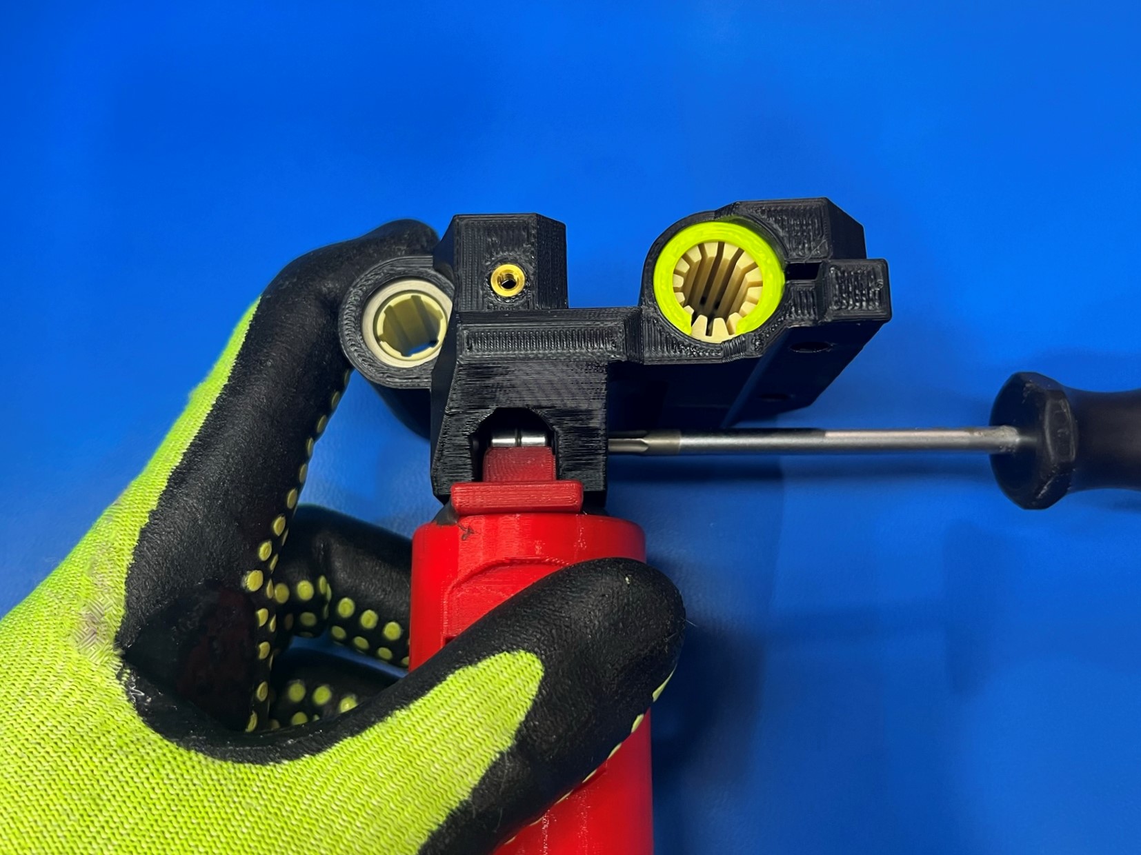
Place 2x rubber sealed bearings [HD-MS0411] inside the idler jig, then place a M5 washer [HD-WA0040] on both sides of the bearings.
Then place the X end idler over the idler jig and secure the bearings and washers with M5x25 SHCS [HD-BT0196] and M5 locknut [HD-BT0057].

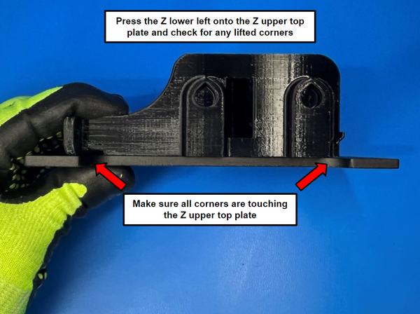
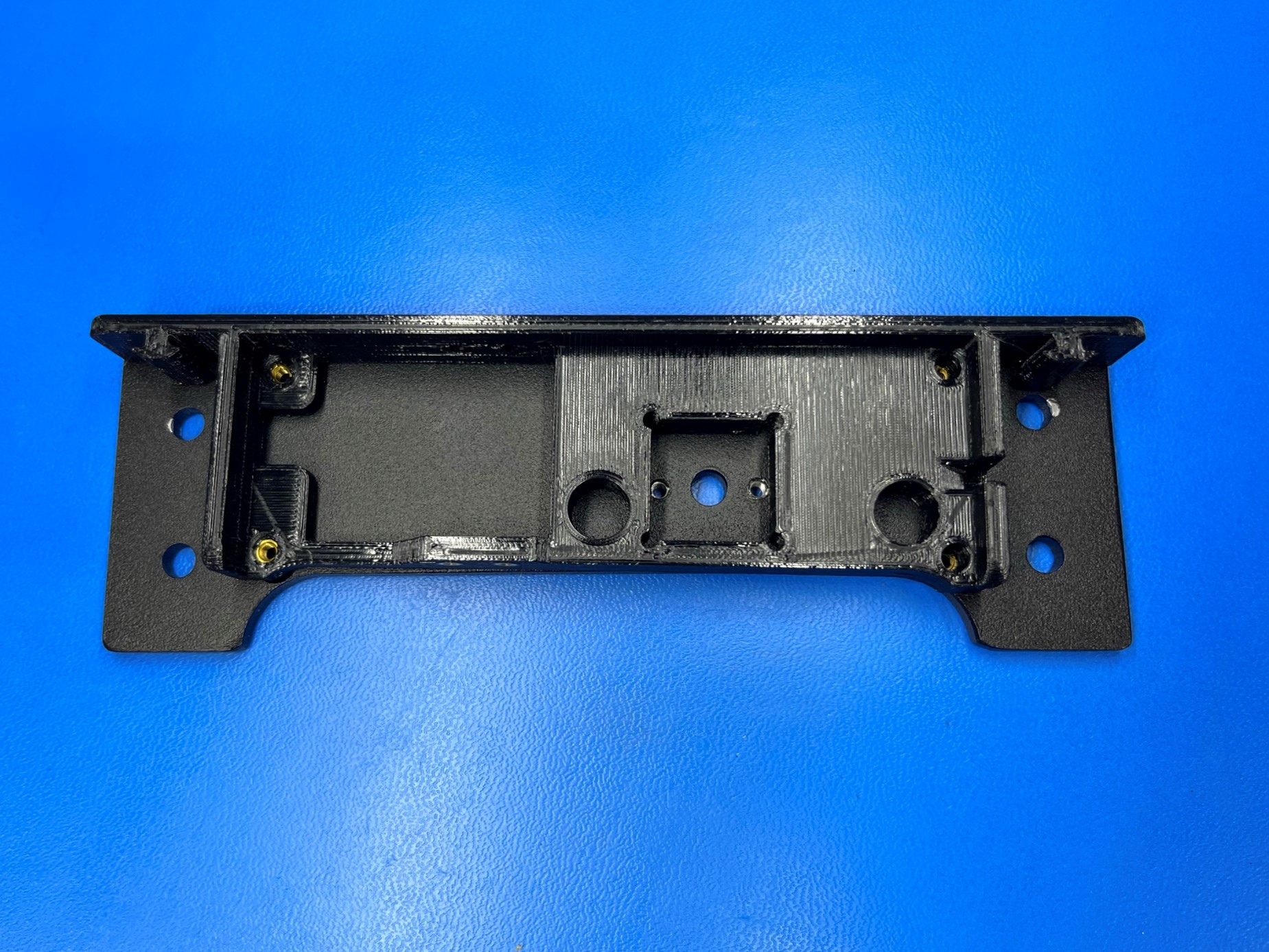
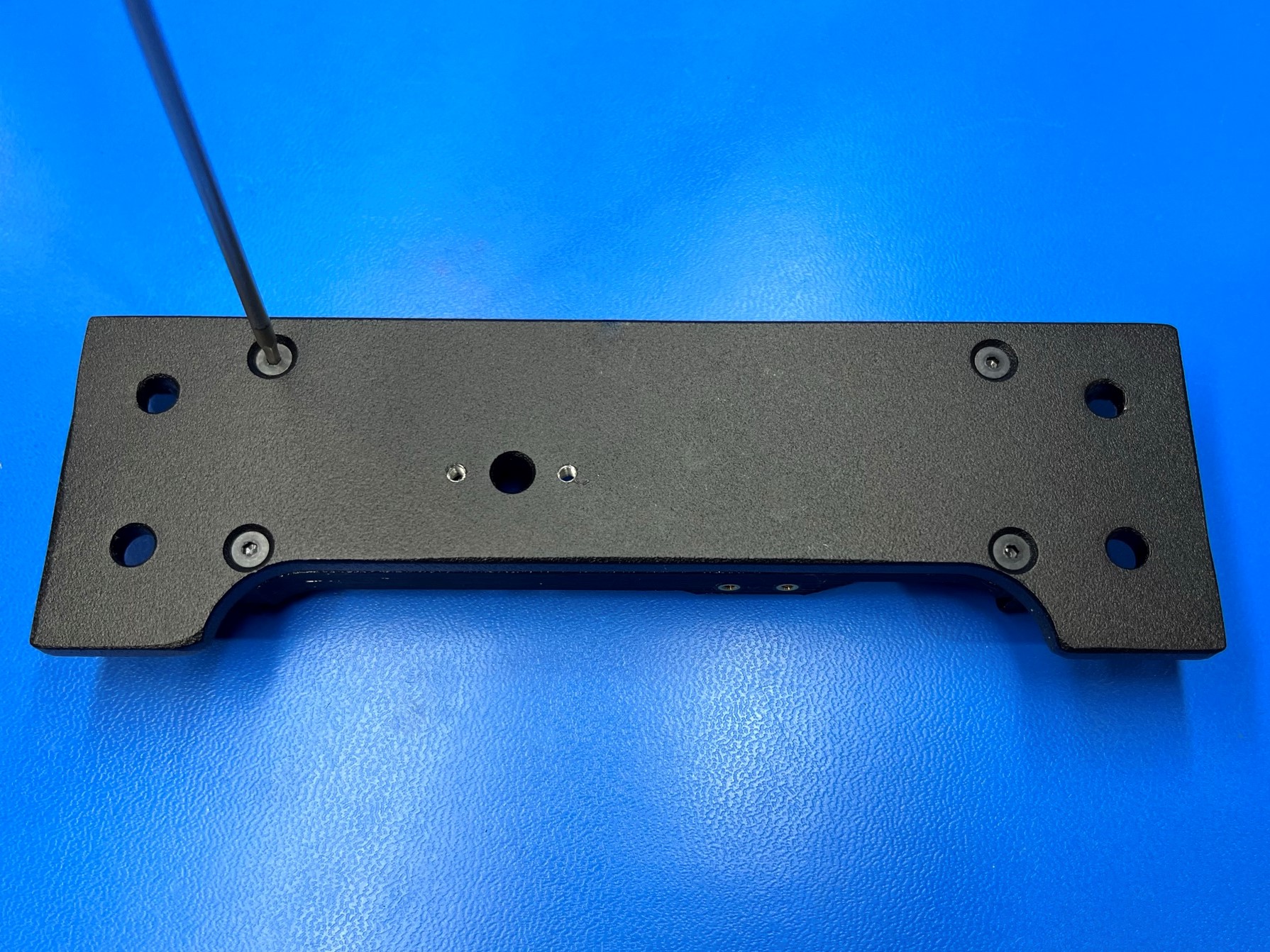
Take the Z upper right [PP-GP0357] and place it on the Z upper top plate [PP-FP0156] making sure the square hole aligns with the three holes in the Z upper top plate.
While holding the two parts together flip them over so that the Z upper top plate is on top, then secure them together using 4x M3x10 FHCS [HD-BT0116].
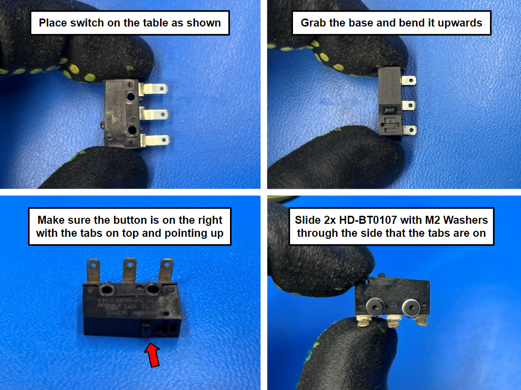
Now take the switch [EL-MS0022] and place it on the table as shown in [reference#1] then take the base of the switch and bend it upwards so the tabs are bent to 90 degrees.
Verify that the button is on the right side when the tabs are on the top and pointing up. If the button is on the left bend the tabs the other way.
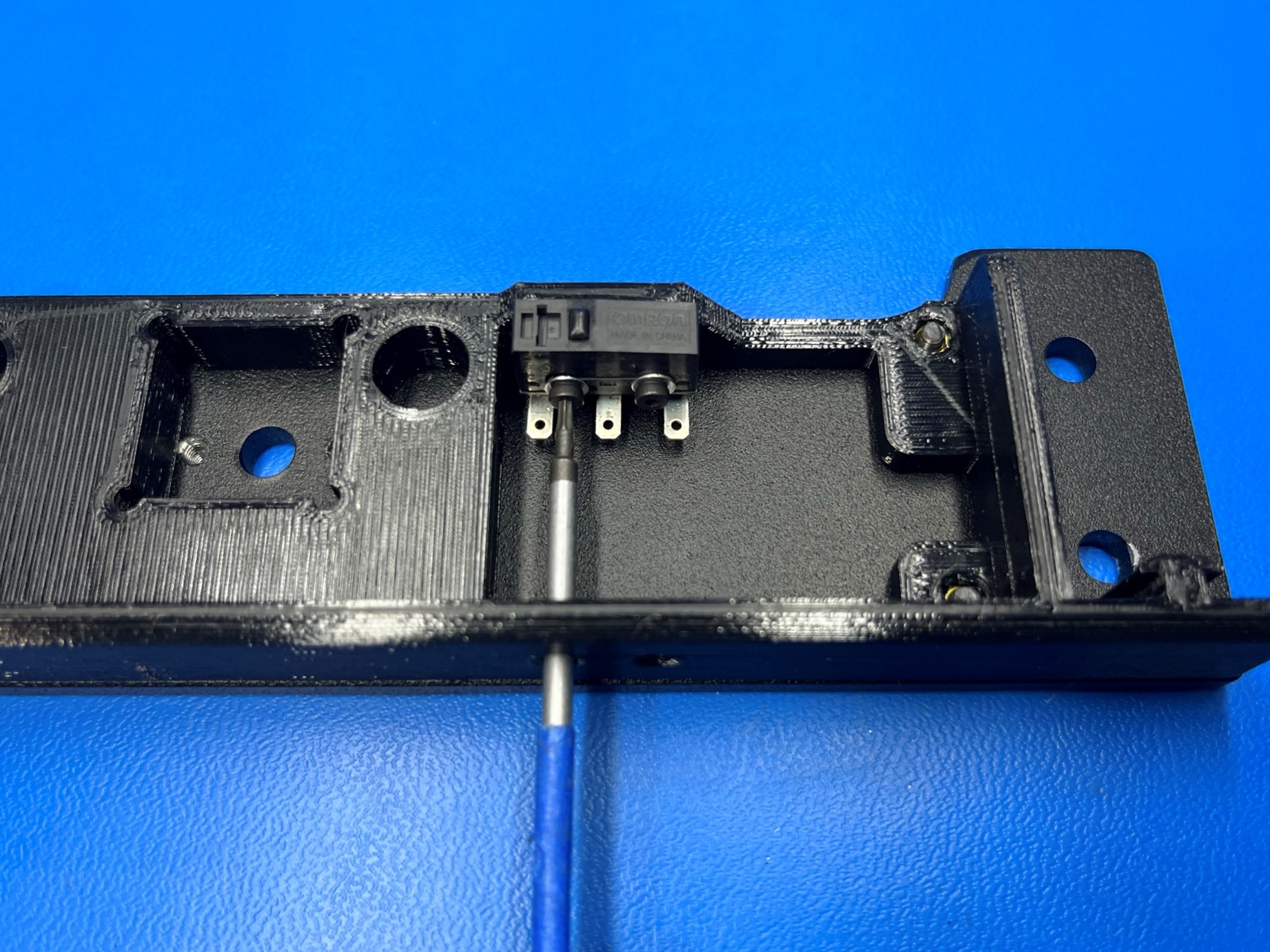
Now slide 2x M2x10 SHCS [HD-BT0107] with M2 washers [HD-WA0012] through the side of the switch that the tabs pointing.
Then fasten the switch to the Z upper right.
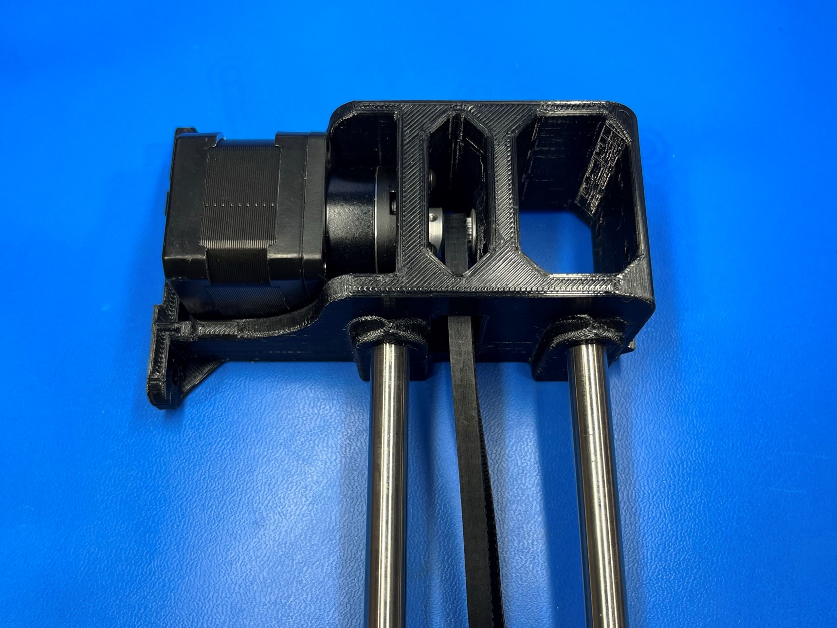
Using the reaming tool, ream both smooth rod holes on the Z lower right.
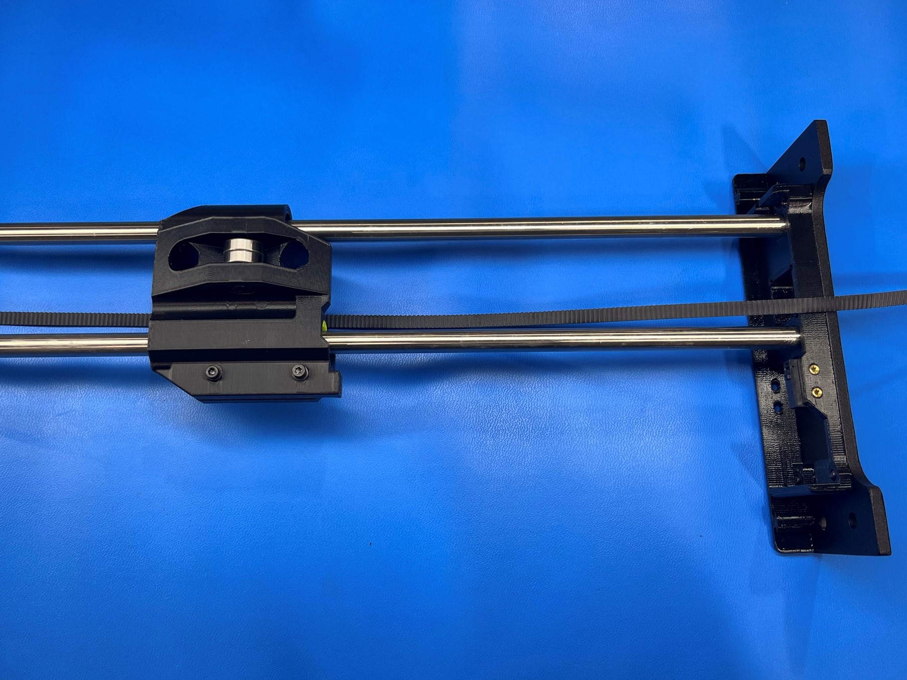
Then slide 2x smooth rods [HD-RD0080] into the smooth rod holes.
Now take the X end idler and slide it onto the smooth rods making sure the bearings are on the opposite side of the flat side of the Z lower right
Take the Z upper right and slide it onto the end of the smooth rods with the flat side on the same side as the flat side of the Z lower right.
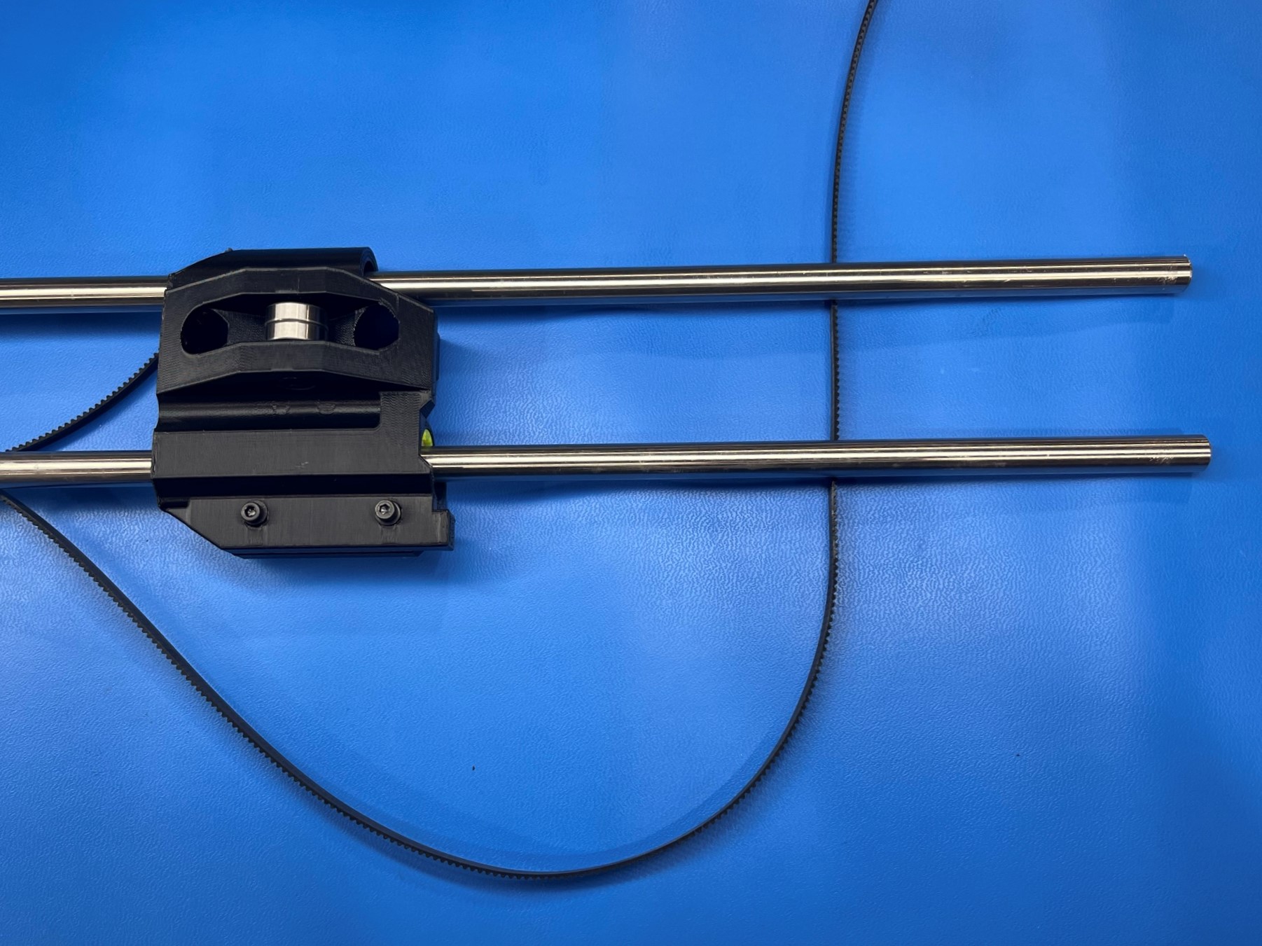

With the Z lower right and Z upper right resting on their flat sides run the belt under the X end idler with the teeth facing up.
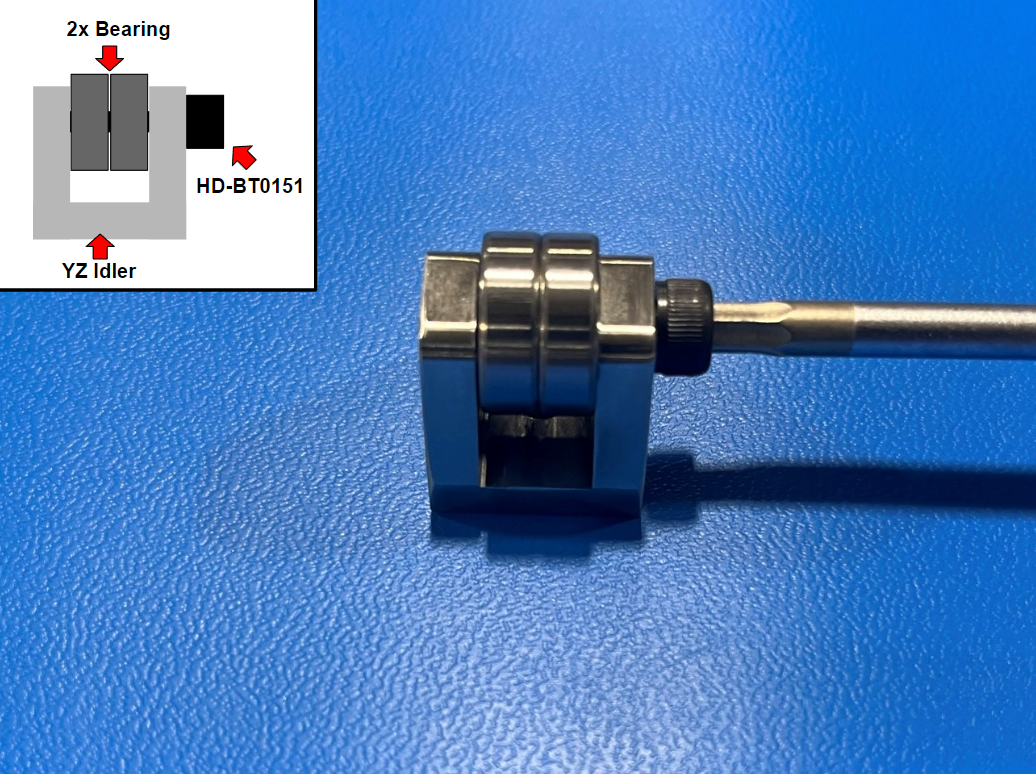
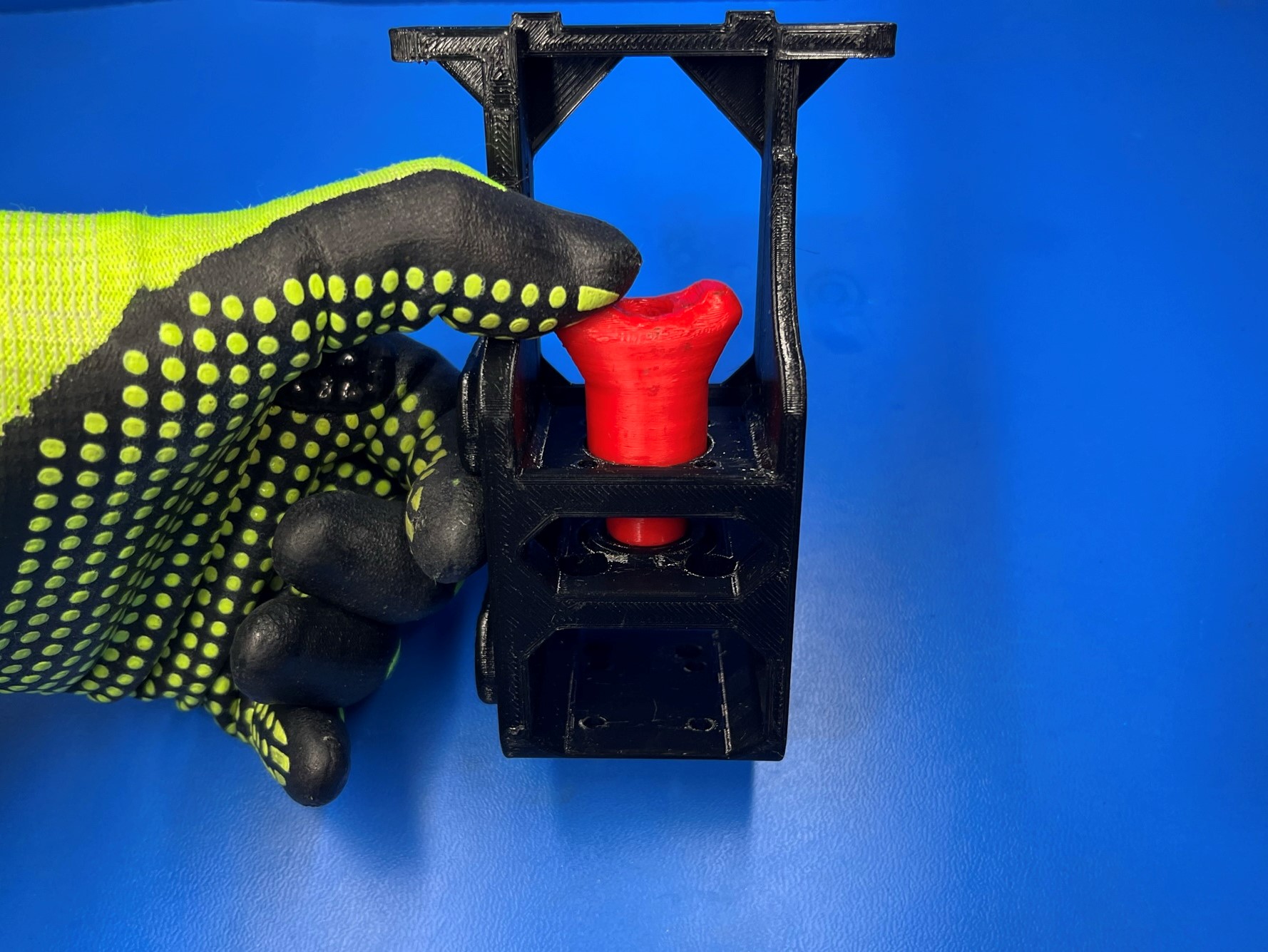
Now use 1x YZ idler [PP-MP0225], 1x M5x20 SHCS [HD-BT0151] and 2x rubber sealed bearings [HD-MS0411] to assemble the YZ idler.
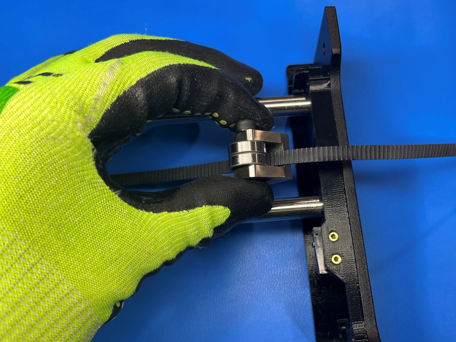
Then take the YZ idler and place it on the table with bolt head facing up and feed the belt around the bearings making sure to start on the right side.
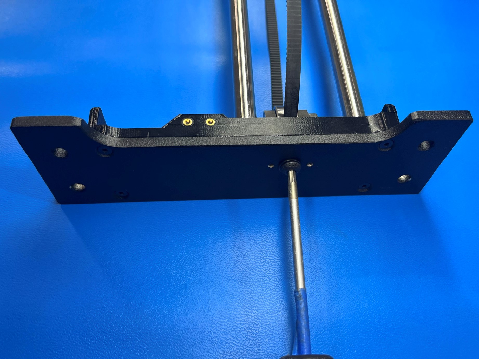
Then pull the YZ idler up to the Z upper top plate and attach it using 1x M5x12 BHCS [HD-BT0158] with a M3 washer [HD-WA0040]. Now install 2x M3 set screws [HD-BT0012] to the Z upper plate.
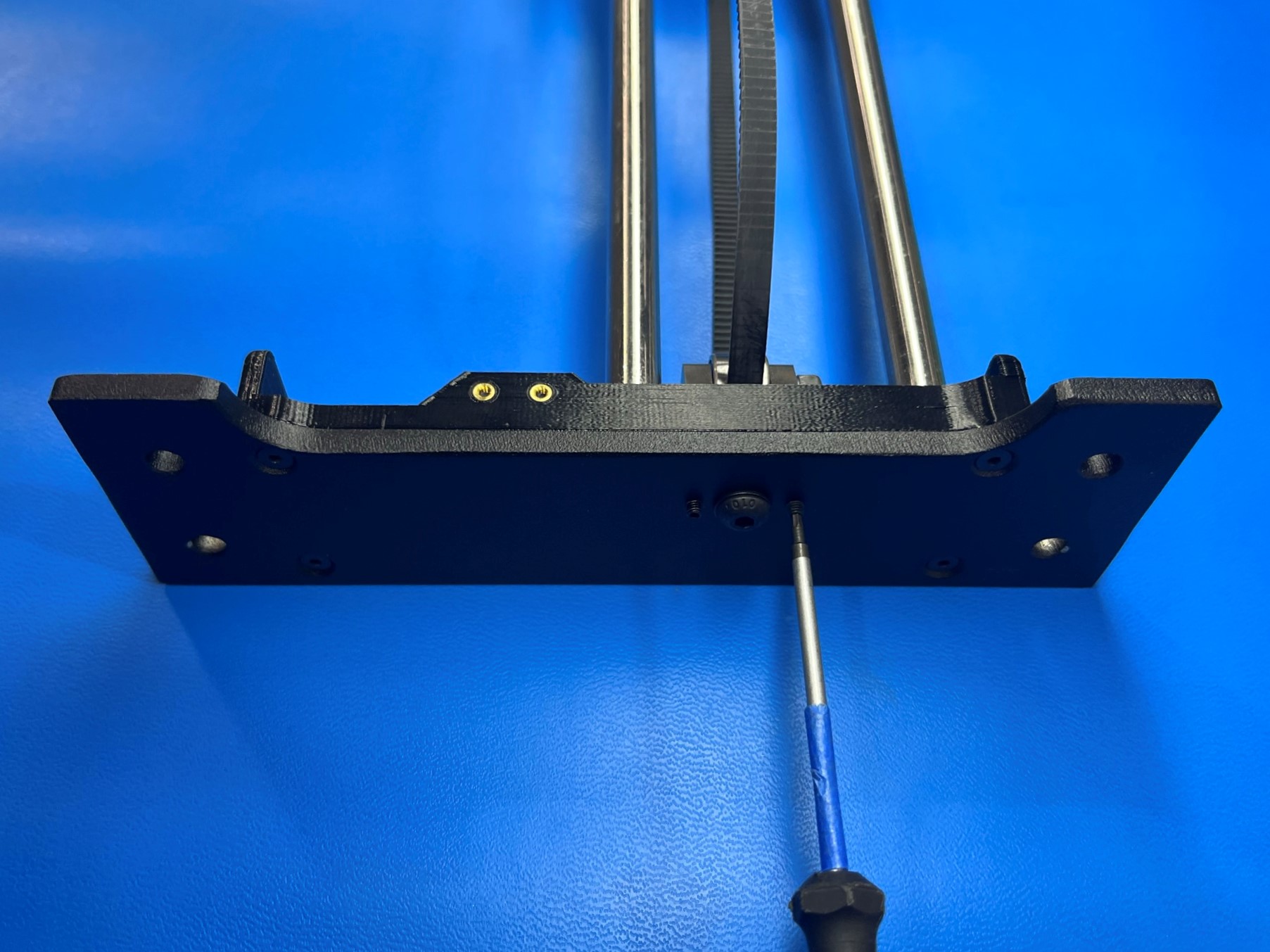
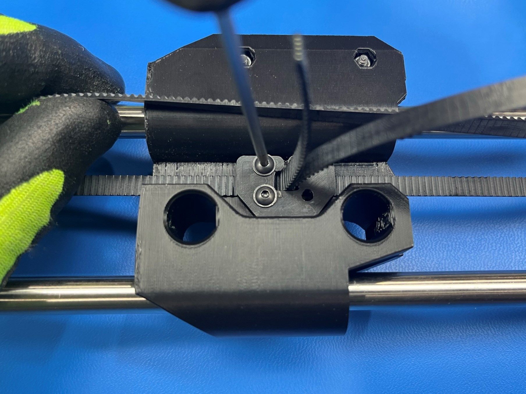
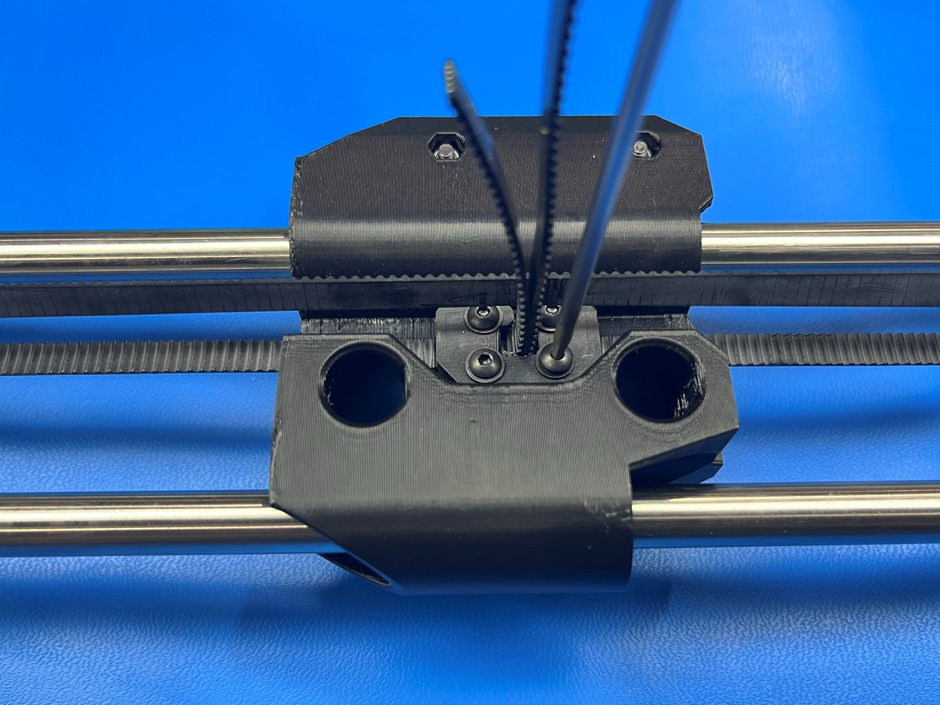
Pull both ends of the belt back to the X end idler and slide the Z axis belt clamp [PP-GP0689] over the ends of the belt aligning it with the X end idler.
Then use 2x M3x10 BHCS [HD-BT0148] with M3 washers [HD-WA0038] and secure one end of the belt to the X end idler.
Now pull on the other end of the belt to tighten it, if the belt is not getting tighter loosen the two screws.
Once the belt is tight use 2x M3x10 BHCS [HD-BT0148] with M3 washers [HD-WA0038] to secure the other end of the belt to the X end idler. If you had to loosen the first two screw tighten them.