Open HardwareAssembly Instructions
Guides for installation and assembly of the LulzBot line of products made by FAME 3D LLC.
Guides for installation and assembly of the LulzBot line of products made by FAME 3D LLC.
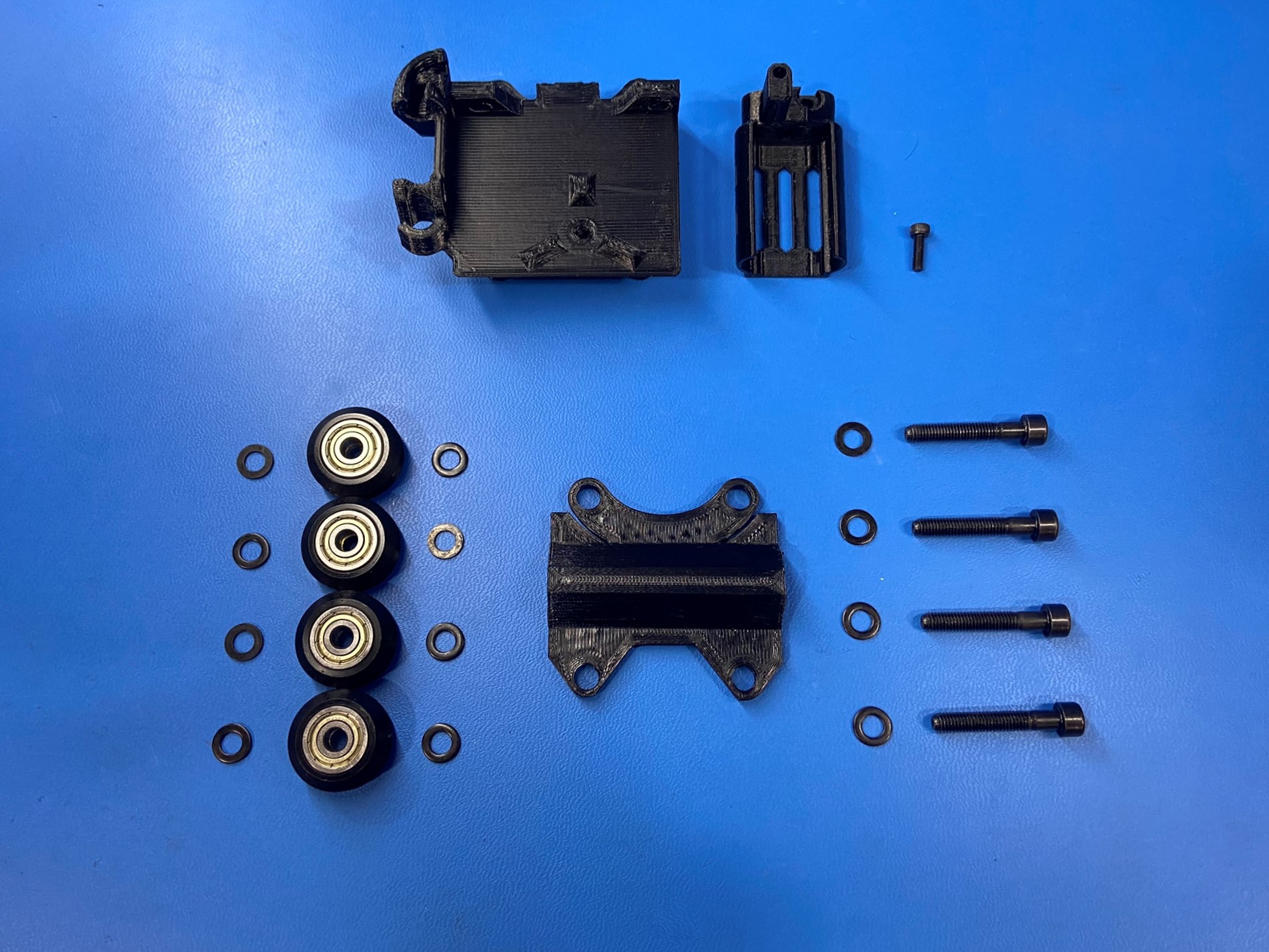
1x- [HD-BT0005] M3x10 SHCS, Black-Oxide
4x- [HD-BT0207] M5x30 SHCS, Black-Oxide
4x- [HD-MS0582] V-Wheel w/ Bearing
12x- [HD-WA0040] M5 Washer
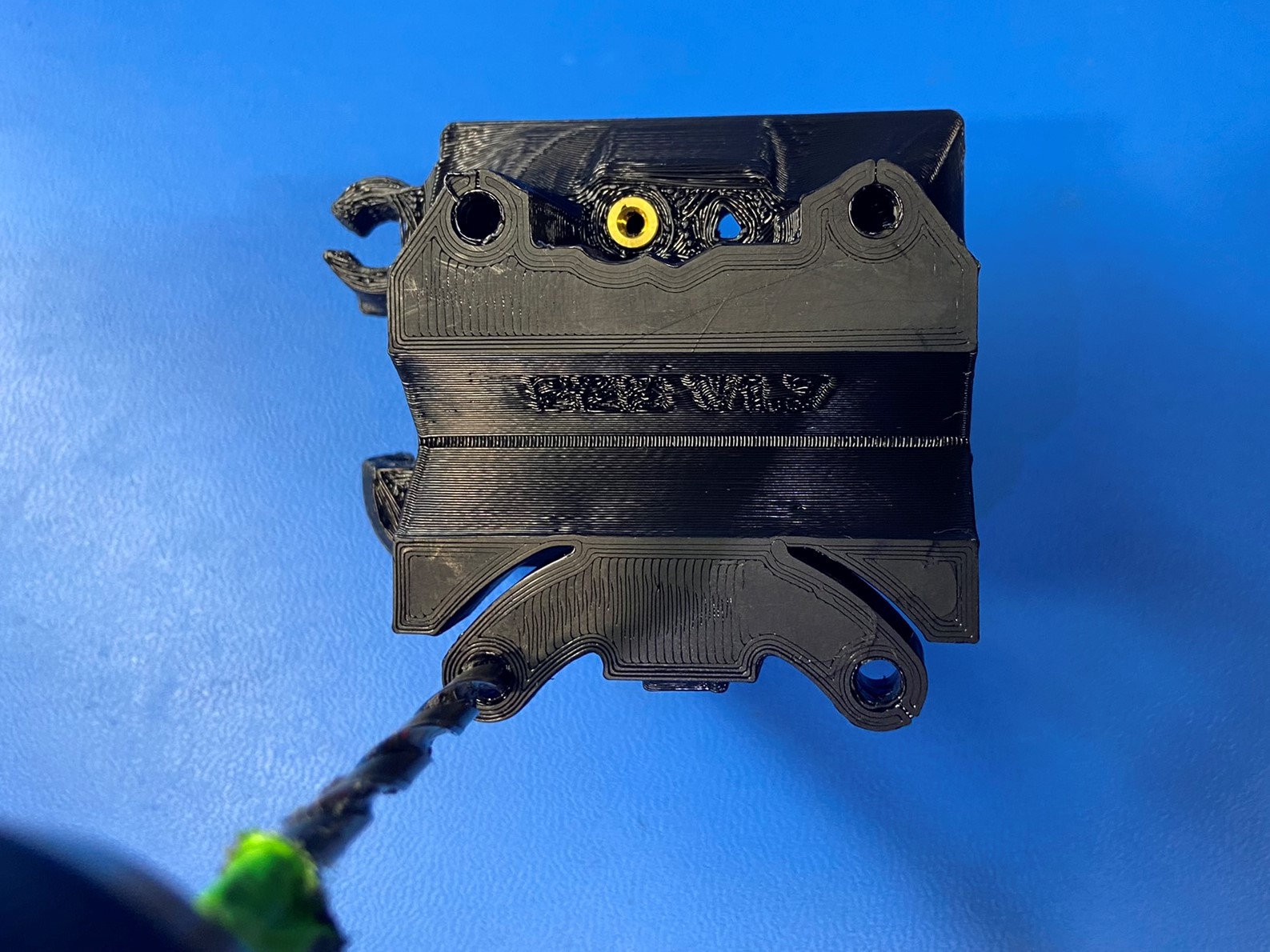
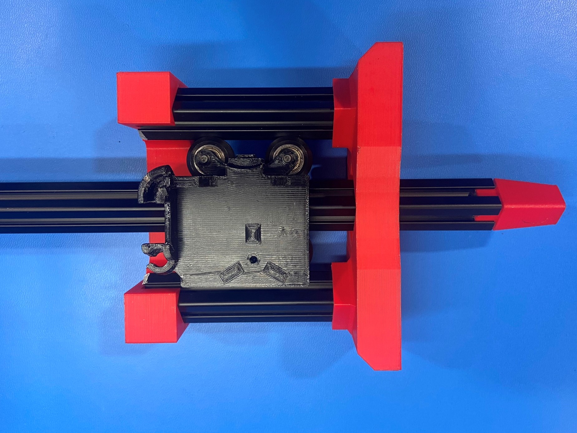
1x- [PP-GP0528] X Carriage
1x- [PP-GP0569] X BLTouch Mount
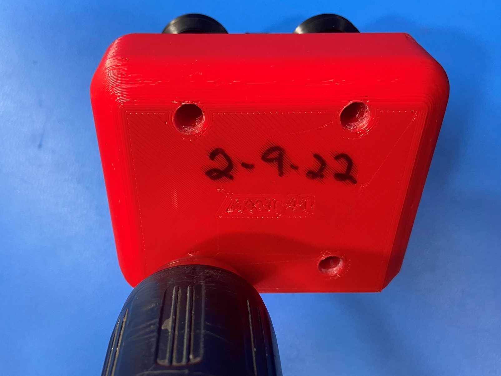
1x- [PP-GP0621] X Carriage Backplate
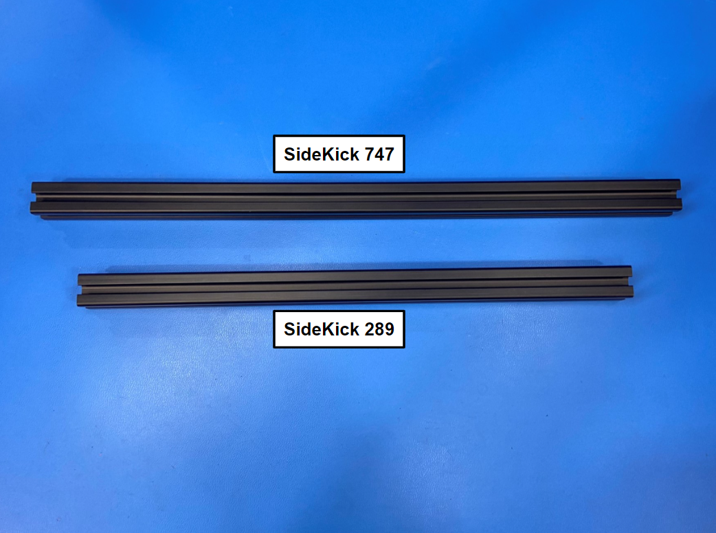
For 289 SideKick
1x- [HD-EX0098] T-Slot Extrusion 334mm
For 747 SideKick
1x- [HD-EX0100] T-Slot Extrusion 397mm
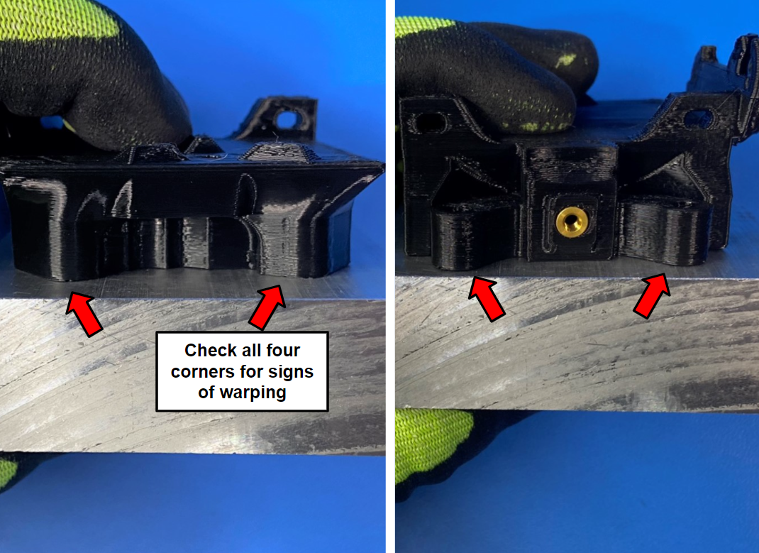
Using the flat block at the work station verify that the X carriage is flat and not lifting on the edges.
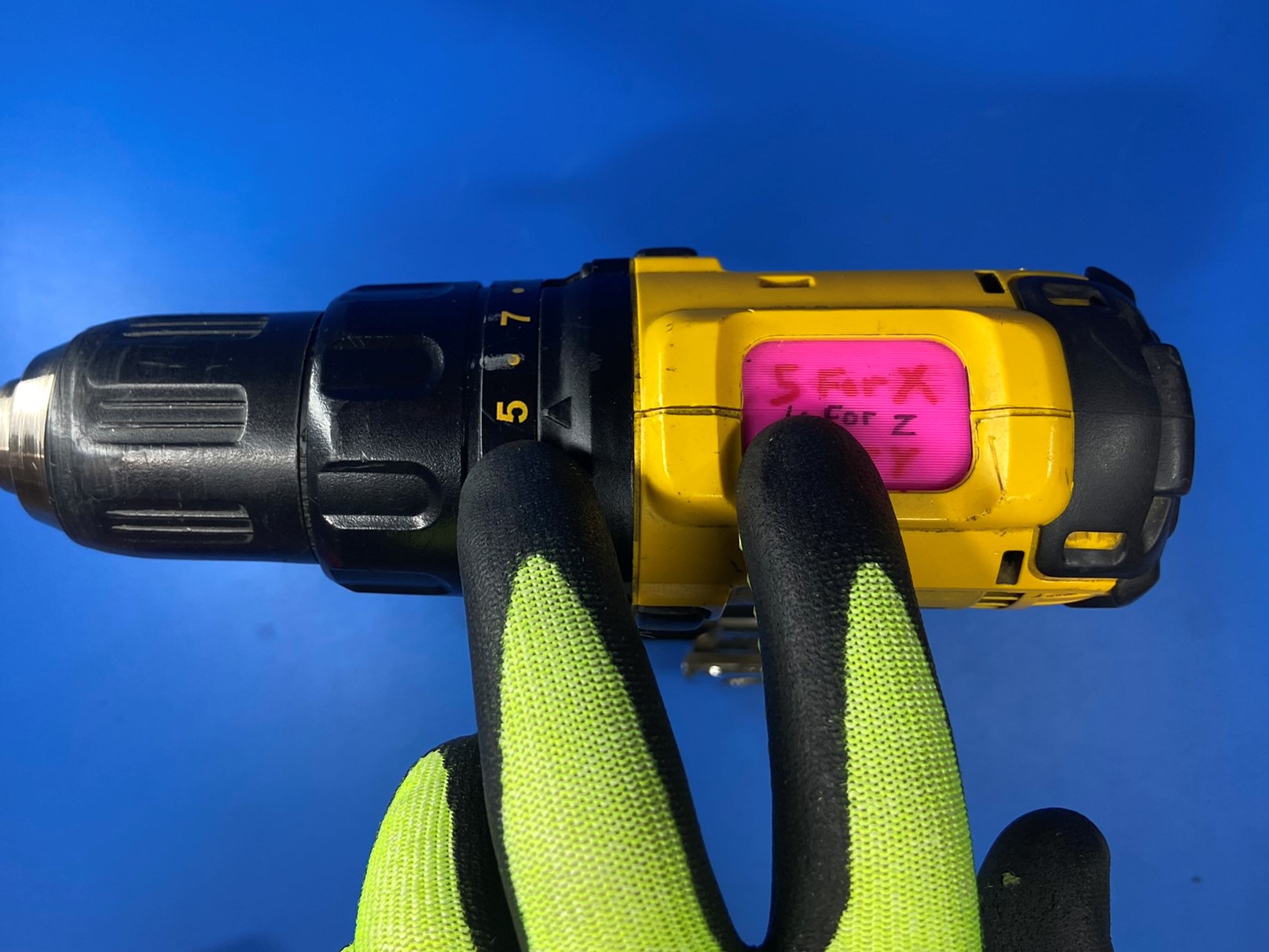
Then use the drill with the drill bit that has the green duct tape on it and drill out all four holes on the X carriage [PP-GP0528].
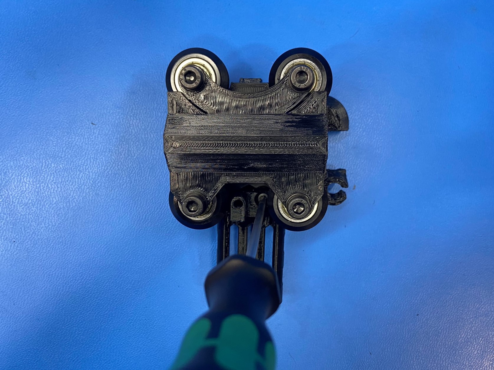
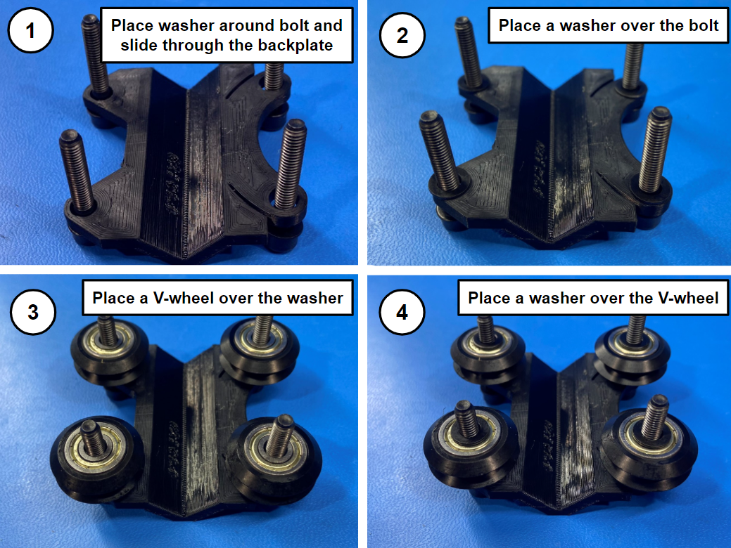
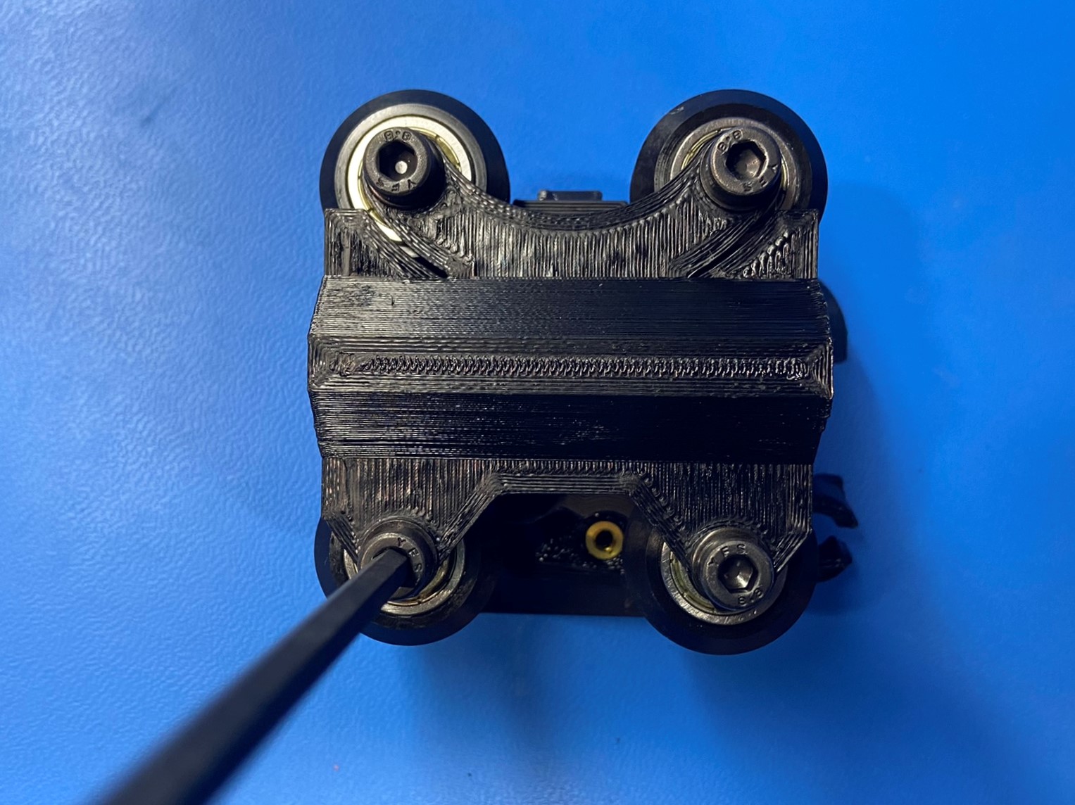
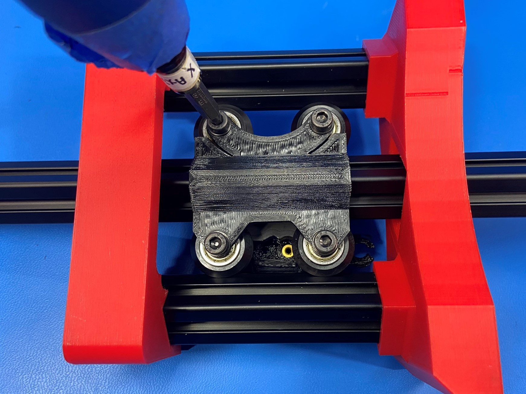
Using 4x M5x30 SHCS [HD-BT0207], 4x V-wheels with bearings [HD-BT0582], 12x M5 washers [HD-WA0040], and the X carriage backplate [PP-GP0569] prepare the backplate with V-wheels.
Start by taking the four bolts and place a washer over them, then slide them through the backplate making sure the point on the V is on the same side as the bolt heads.
Then place another washer over the bolts, next place the V-wheels over the bolts, then place another washer over the bolt.
Order: BOLT HEAD - WASHER - BACKPLATE - WASHER - V-WHEEL - WASHER
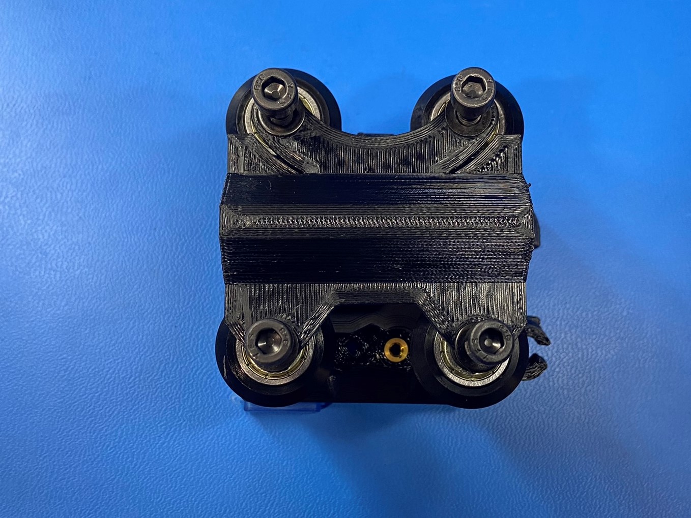
Then loosely fasten the bolts into the four drilled out hole on the X carriage. Make sure the round sides on the backplate and the x carriage match up.
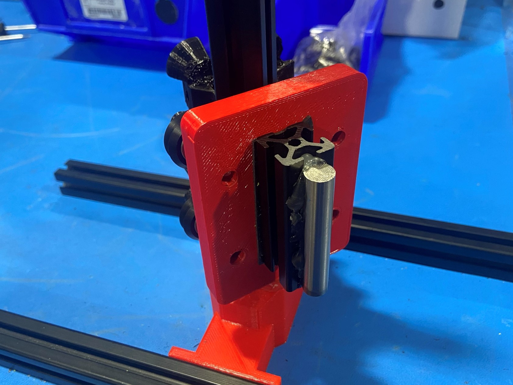
Then place the squaring jig over the X carriage backplate, you may need to move the bolt heads around.
Using the drill tighten the bolts.
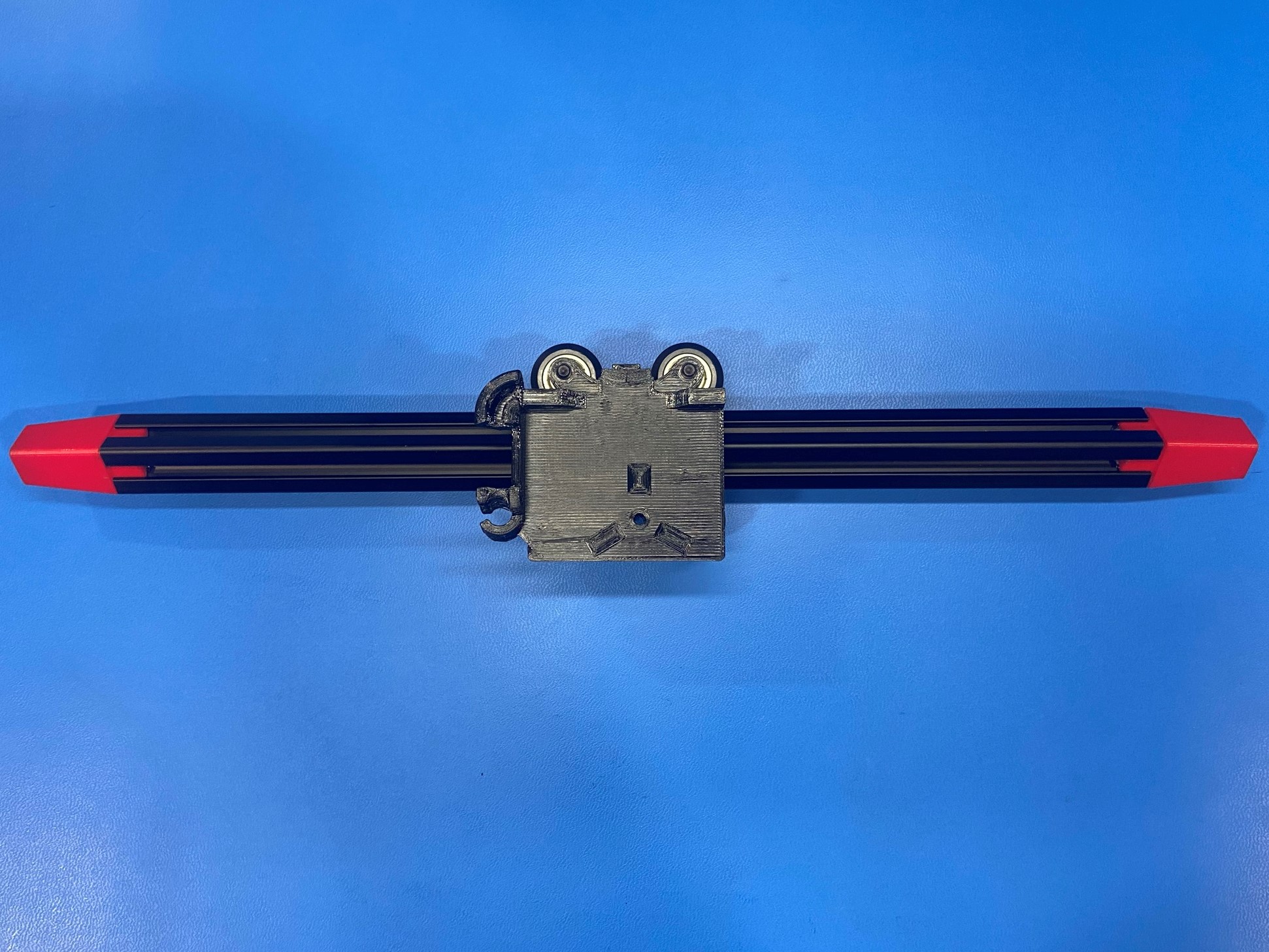
Loosen the four bolts by a half a turn, then slide the X carriage onto the extrusion will the two red end caps.
Take the extrusion and slide it into the X carriage cage jig making sure the front side of the X carriage is facing upward.
Then slide the extrusion back and forth so the V-wheels are properly seated. Then torque the four bolts to 17 in*lbs

Depending on what printer you are making use the T-slot extrusion 334mm [HD-EX0098] for the 289 SK or if you are building the 747 SK use the T-slot extrusion 397mm [HD-EX0100]
Once you determined what printer you are making place the extrusion inside the extrusion stand located at the work station.
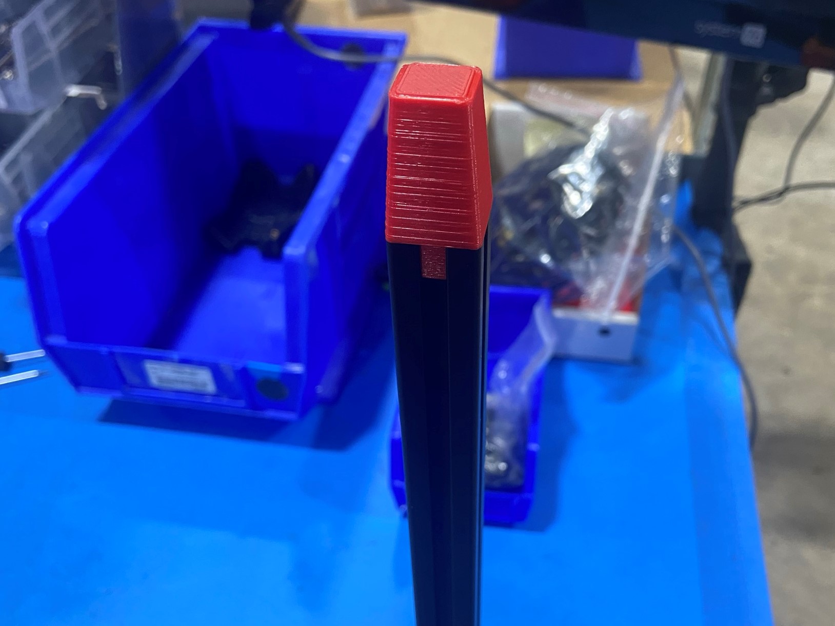
Then place the red end cap on the top end of the extrusion, this protects the V-wheels from the edge of the extrusion.
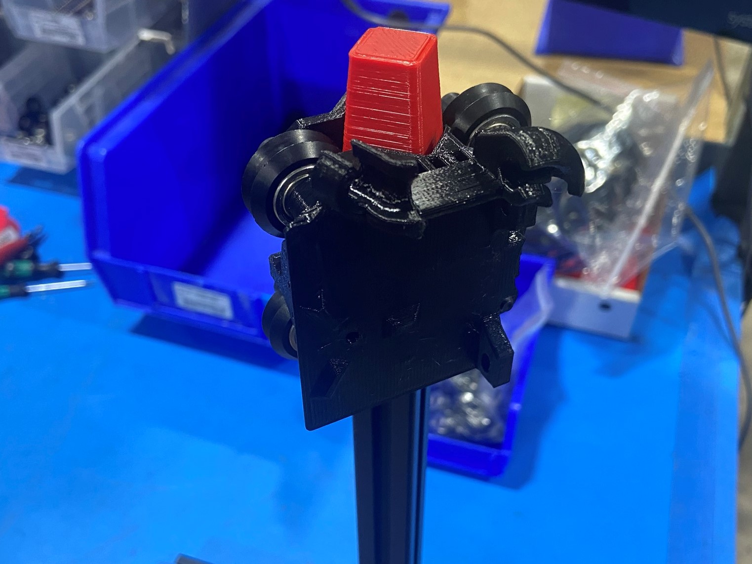
Now slide the X carriage onto the extrusion and make sure it stays in place.
Finally place the weighted jig on the head of the bolts and you should see the X carriage slowly fall down.
WARNING
If you see any of the following things happen tag the assembly and report to Line Lead for addition instructions!

Using M3x10 SHCS [HD-BT0005] attach the X BLTouch mount [PP-GP0569] to the X carriage.