Open HardwareAssembly Instructions
Guides for installation and assembly of the LulzBot line of products made by FAME 3D LLC.
Guides for installation and assembly of the LulzBot line of products made by FAME 3D LLC.
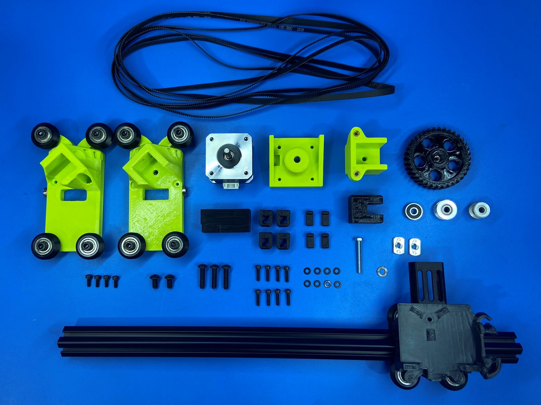
1x- [EL-MT0069] NEMA 17 Half Height Stepper Motor
3x- [HD-BL0032] Single Sided Neoprene Belt 1164mm
8x- [HD-BT0039] M3x12 SHCS, Black-Oxide
2x- [HD-BT0073] M5x10 BHCS, Black-Oxide
5x- [HD-BT0157] M3x8 SHCS, Black-Oxide
1x- [HD-BT0266] M4x30 HHCS, Black-Oxide
3x- [HD-BT0272] M5x20 BHCS, Black-Oxide
1x- [HD-MS0033] 16 Teeth Timing Pulley
1x- [HD-MS0411] Premium Two Side Rubber Sealed Bearing
1x- [HD-MS0593] 5mm Smooth Bore Idler
2x- [HD-NT0053] M5 T-Slot Nut
8x- [HD-WA0038] M3 Washer
1x- [HD-WA0040] M5 Washer
1x- [PP-GP0527] X Motor Mount
1x- [PP-GP0530] X Tensioner Guide
4x- [PP-GP0532] Belt Clamp
1x- [PP-GP0557] XYZ Tensioner Knob
1x- [PP-GP0580] X Carriage Strain Relief
1x- [PP-GP0581] XY Belt Tensioner
4x- [PP-GP0649] Belt Clamp Sled
2x- Reusable clips
X Motor Assembly
X Axis Idler Assembly
X Carriage Assembly
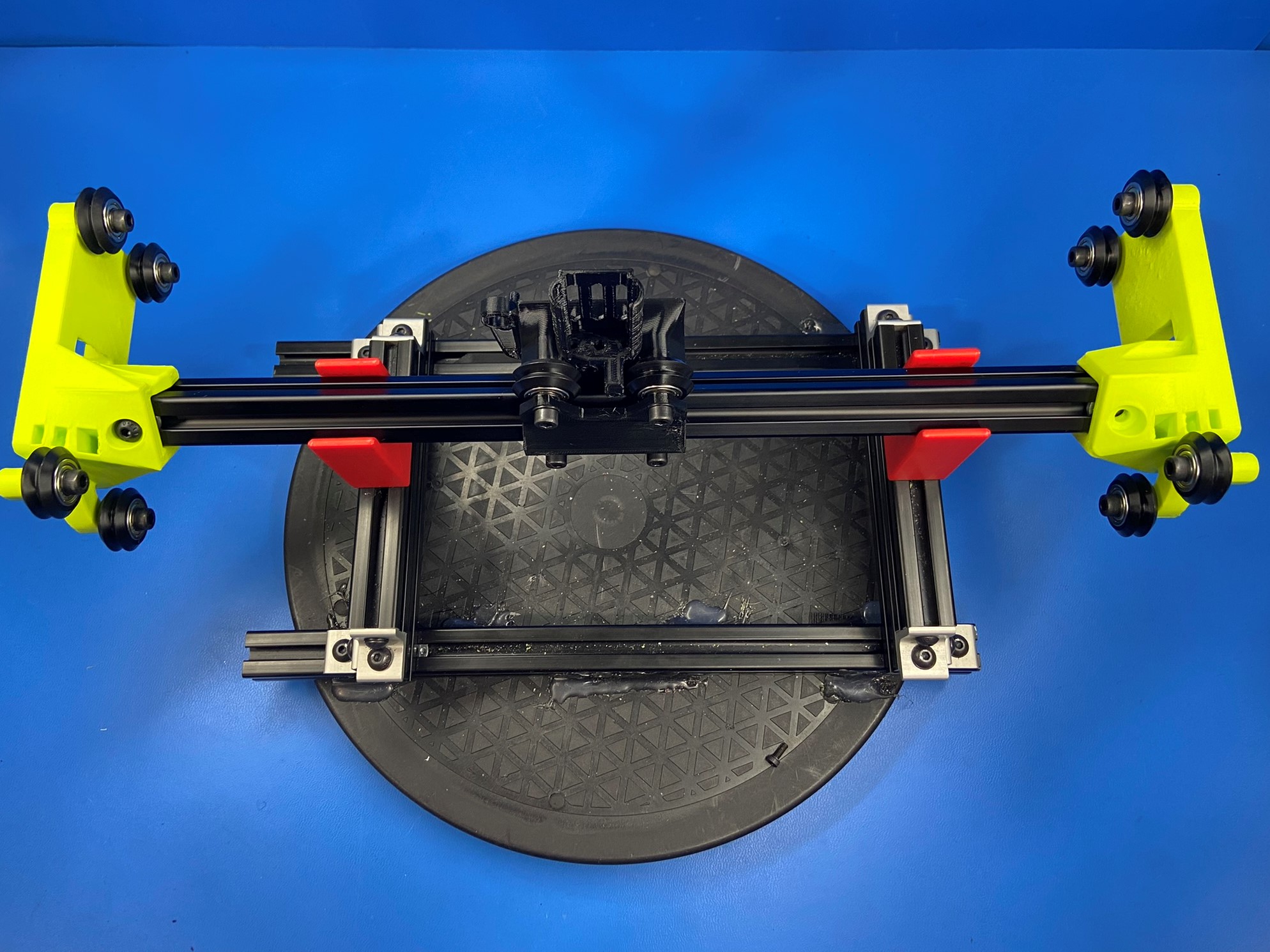
Place the X carriage assembly on the jig provided at the work station. Note: Make sure the bottom side of the X carriage is facing up and that the back place is facing the front of the table.
Then slide 1x M5 T-slot nut inside the side of the extrusion that is facing you repeat for the other side.
Slide the X motor assembly on the left side of the extrusion making sure the hole on the X motor aligns with the T-slot nut previously placed.
Start tightening 1x M5x20 BHCS [HD-BT0272] with a screw driver making sure not to cross-thread the extrusion.
Then fully tighten using a drill.
Use 1x M5x10 BHCS [HD-BT0073] and the T-slot nut to secure the side of the X motor.
Repeat steps for attaching the X axis idler on the other end of the extrusion.


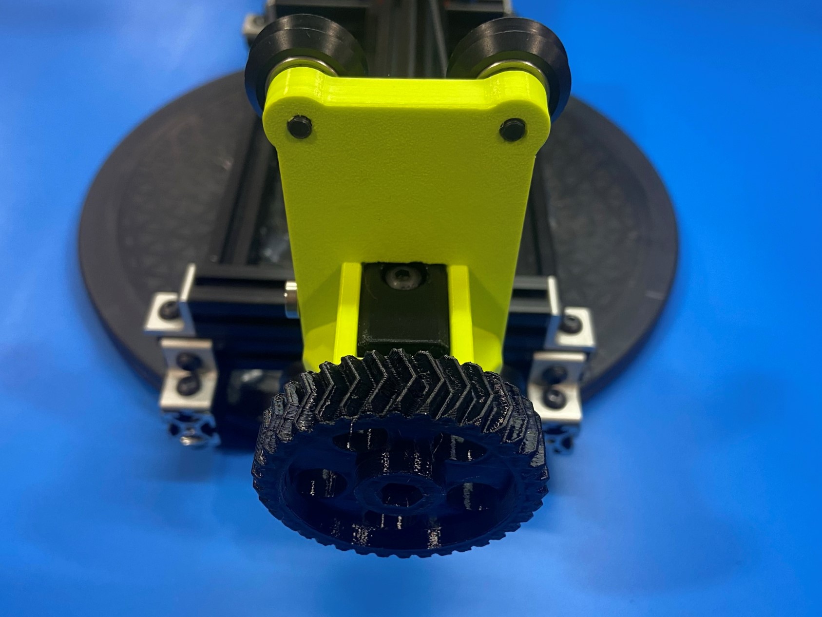
Using 1x 16 teeth timing pulley [HD-MS0033] and the X motor spacing jig install the timing pulley to the NEMA 17 half height stepper motor [EL-MT0069] while pushing down on the pulley to ensure correct spacing.
Note: make sure one of the set screws is on the flat side of the motor shaft.
Then take the X motor mount [PP-GP0527] and using the bearing plunger jig firmly push 1x rubber sealed bearing [HD-MS0411] inside the cavity on the X motor mount. Make sure bearing is fully seated or the timing pulley will rub on it.
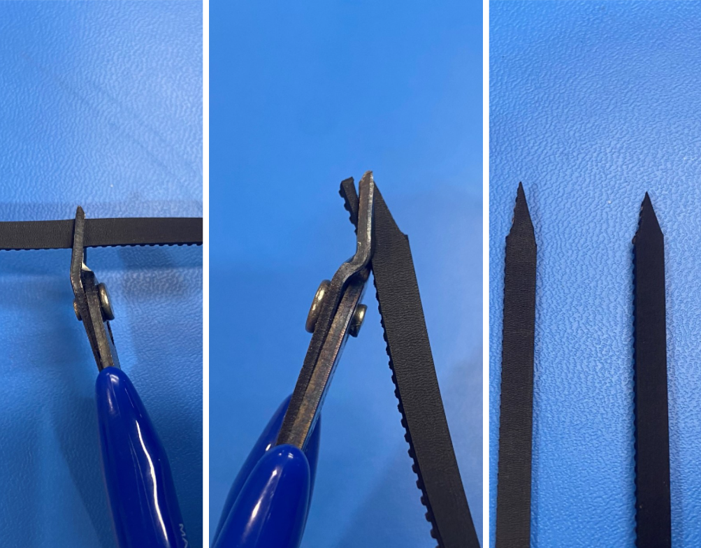
Cut the single sided neoprene belt [HD-BL0032] in half, then trim both ends so there is a narrow point.
This will help to feed the belt through the X carriage.
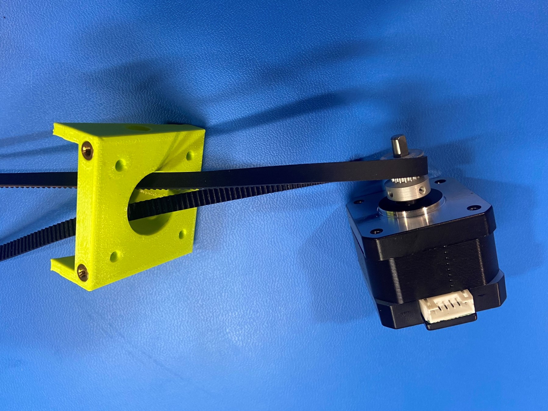
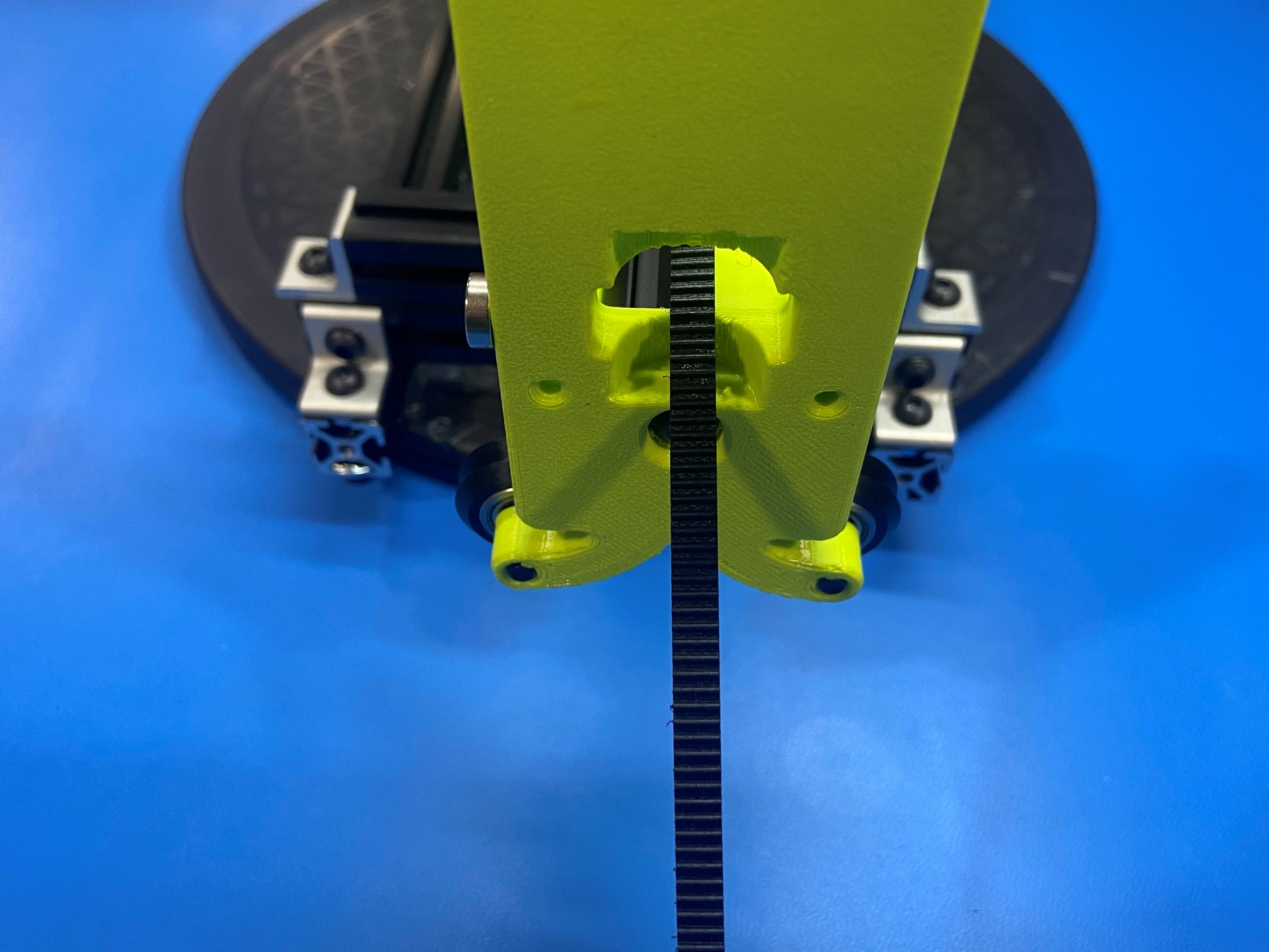
Bend the belt in half then push the looped end through the X motor mount, then loop the belt around the timing pulley. [reference#1]
Using 4x M3x12 SHCS [HD-BT0039] along with 4x M3 washers [HD-WA0038] secure the stepper motor to the X motor mount.
Note: make sure to align the wire port on the stepper motor with the side of the X motor mount that has a hole on it.
Then take both ends of the belt and feed them through the rectangular hole on the X motor assembly. Then align the brass inserts on the X motor mount with the two holes on the X motor assembly.
Rotate the extrusion so the front on the X carriage is facing up then, using 2x M3x12 SHCS and 2x M3 washers secure the X motor mount to the X motor assembly.
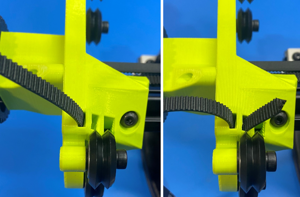
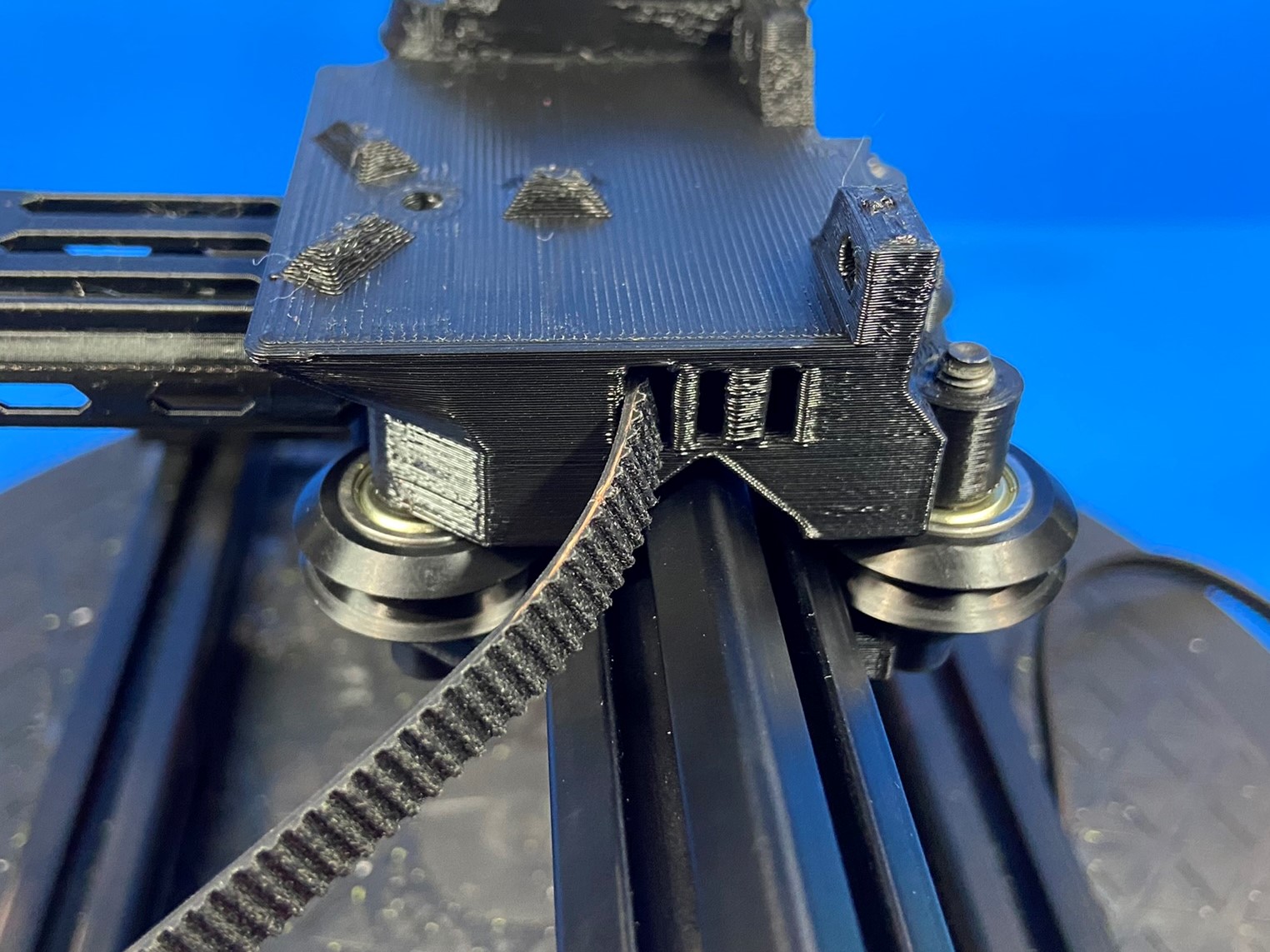
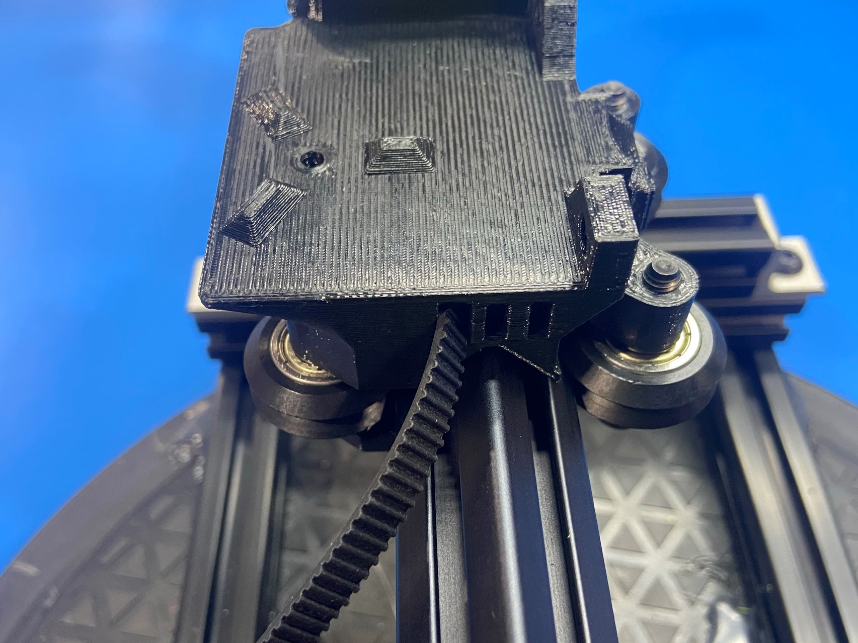
Then route the belt through the hole on the X carriage that goes all the way through (closest hole to you if the bottom side of the X carriage is facing you).
Note: make sure the teeth are facing towards the other end of the belt. (Belt teeth should always be on the inside of the belt loop)
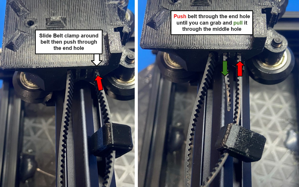
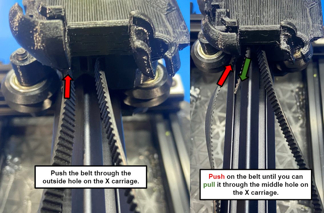
Now take the other end of the belt and slide 1x belt clamp [PP-GP0532] over the belt. Then push the belt through the outside hole on the X carriage and push the on the belt until the end comes through the center hole. Make sure to slide the belt clamp over the belt or you will have to start this step over
Note: if the belt is stuck you can try to trim the end so it is narrower or use a tweezer or pliers to pull then end through.
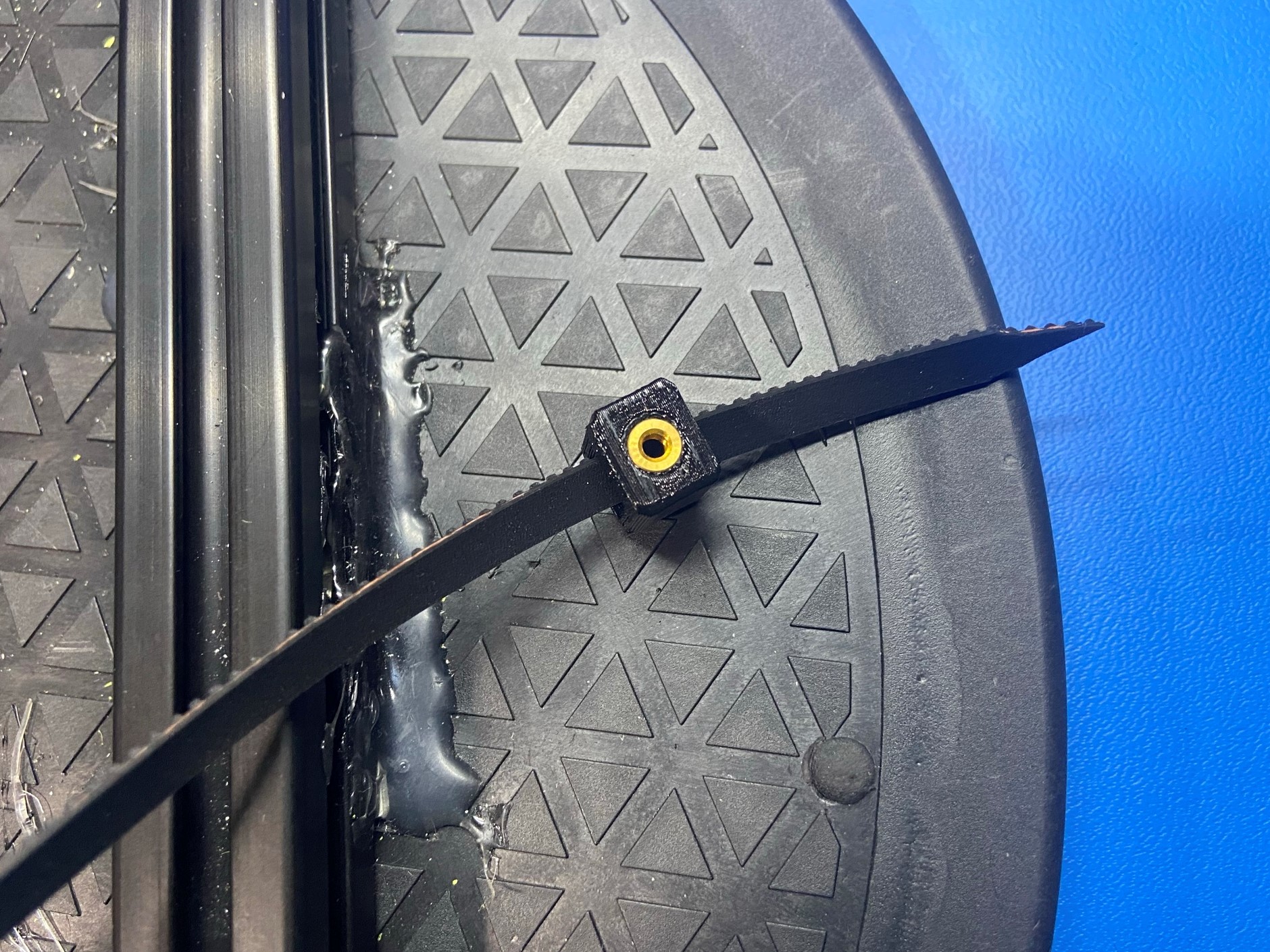
Once the belt is looped through the X carriage slide the belt clamp around the overlapped belt and slide 1x belt clamp sled [PP-GP0649] in between the belt clamp and the belt.
Then use 1x M3x8 SHCS to secure the belt clamp and belt sled.


Route the belt end through the X axis idler assembly.
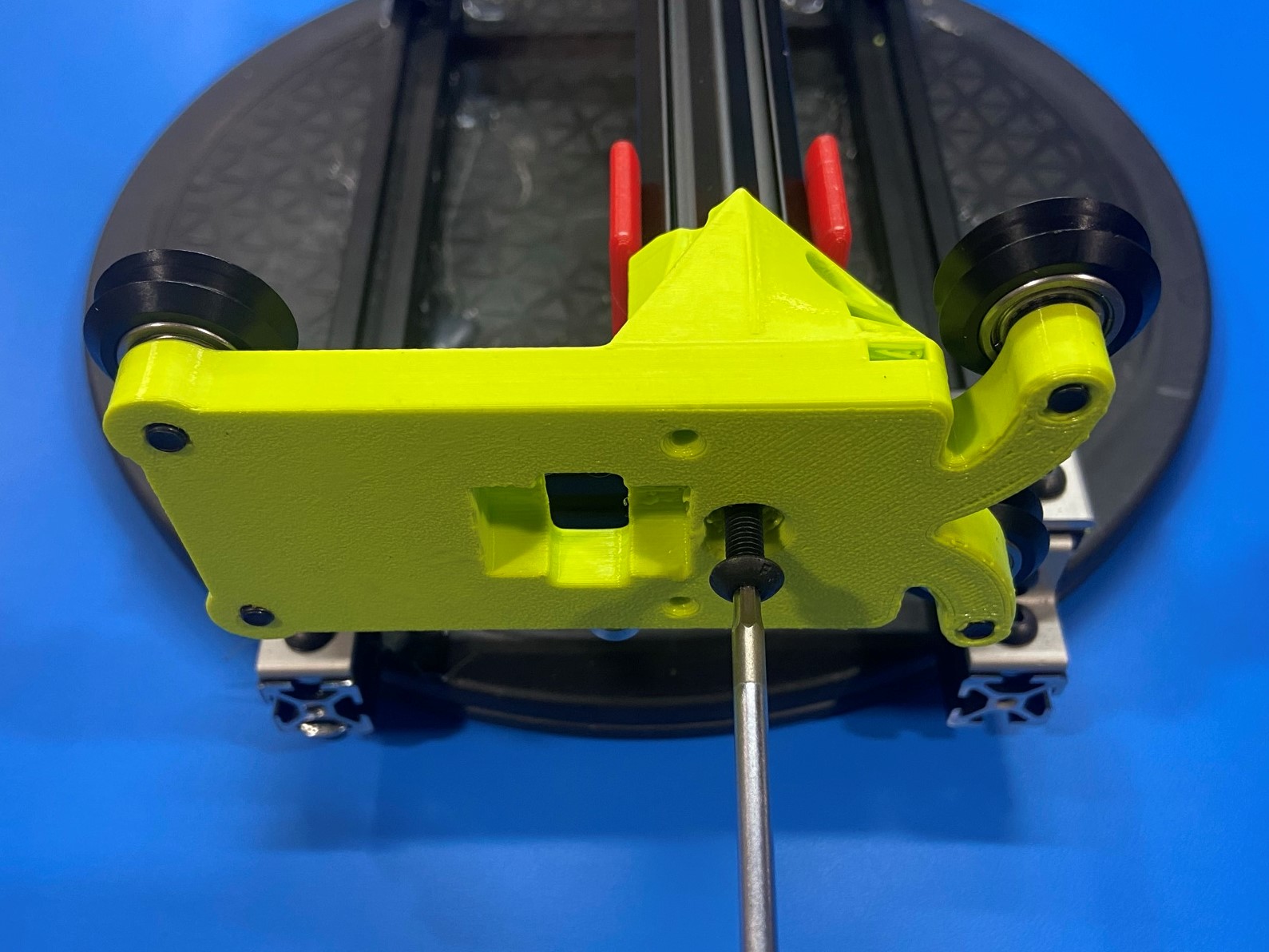
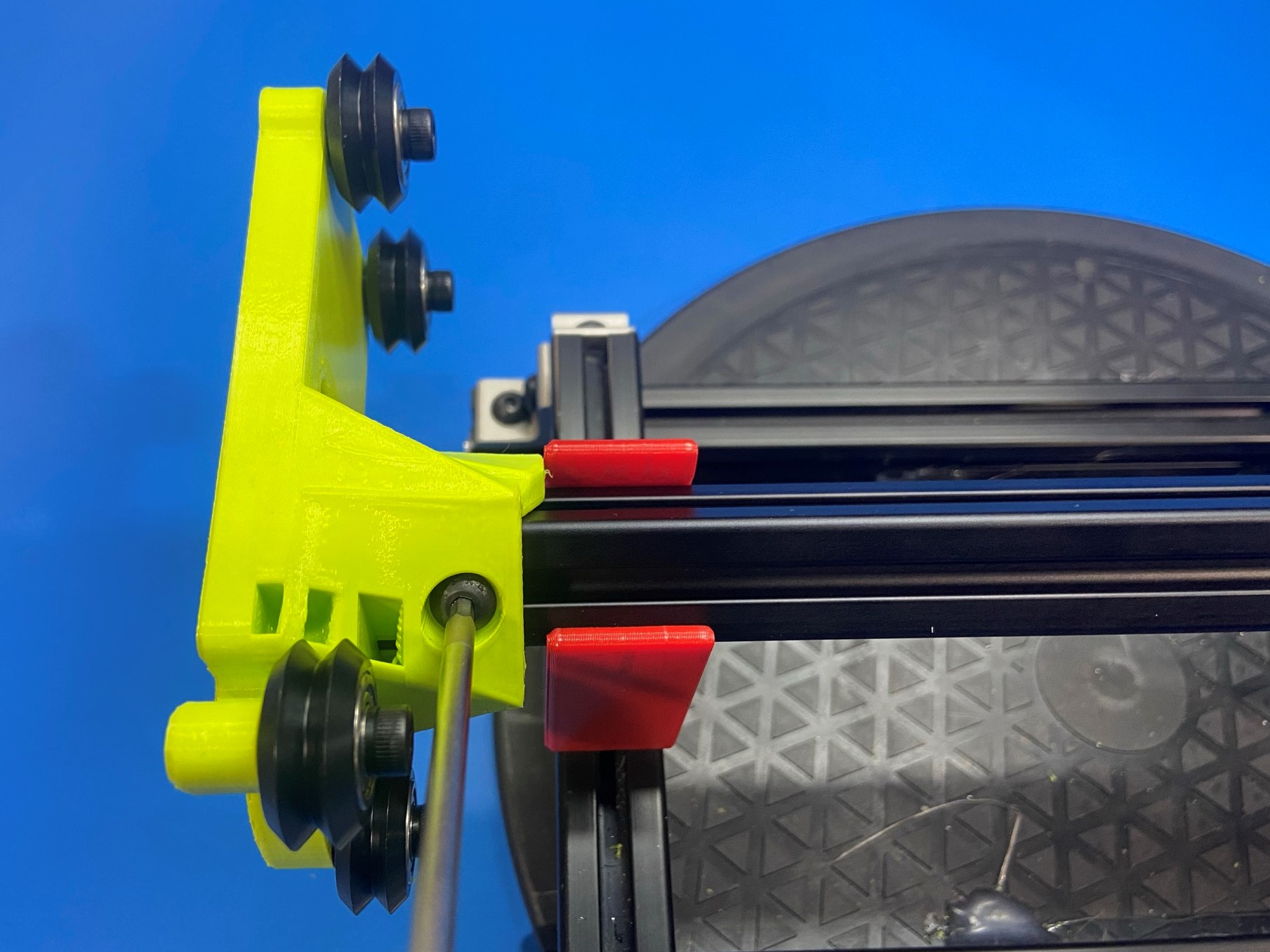
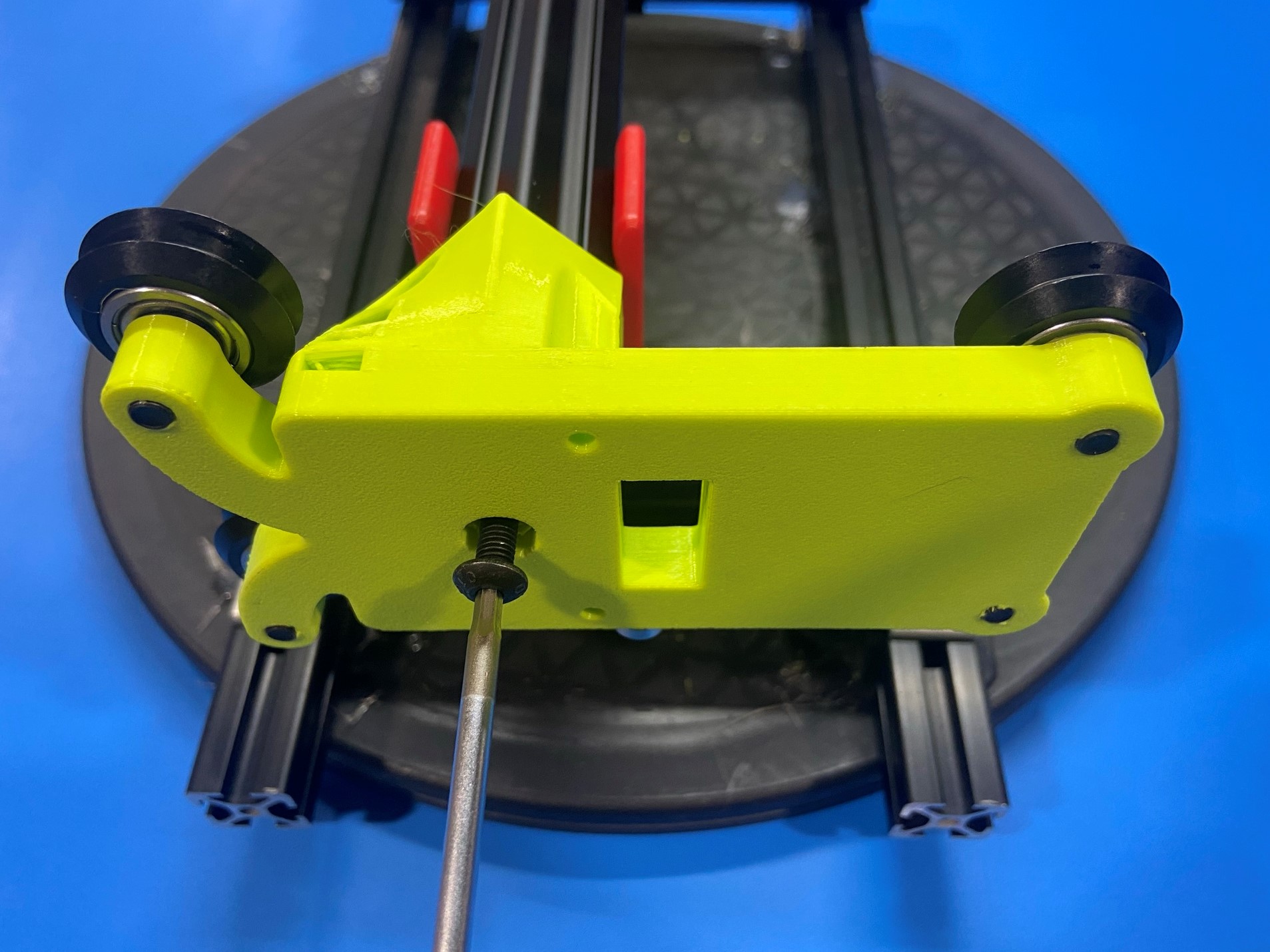
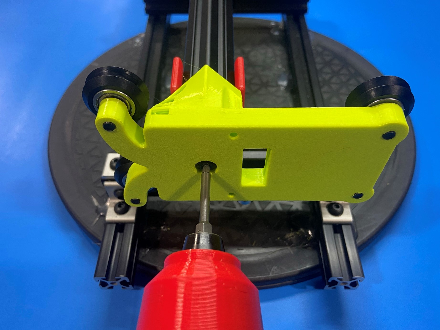
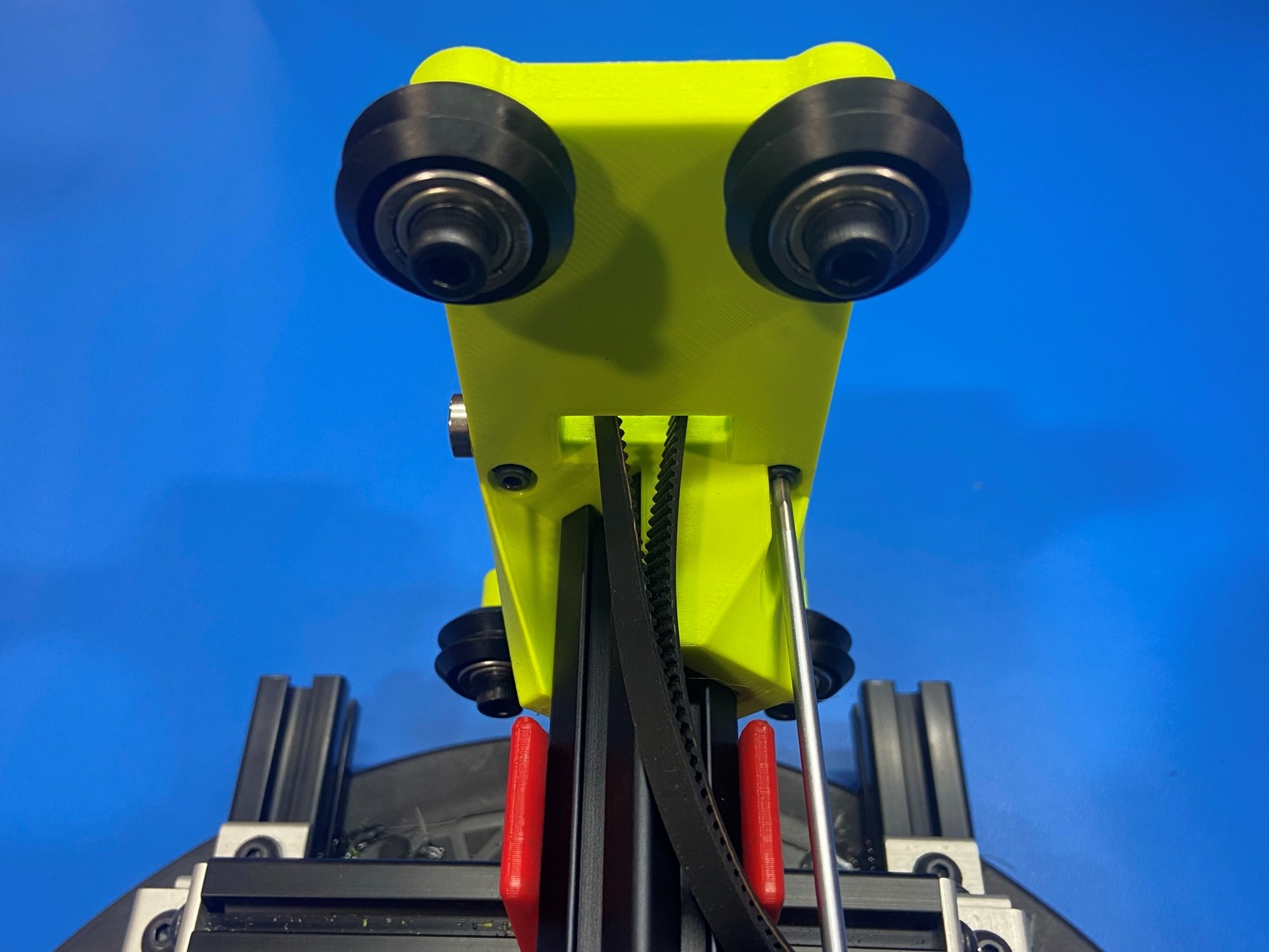
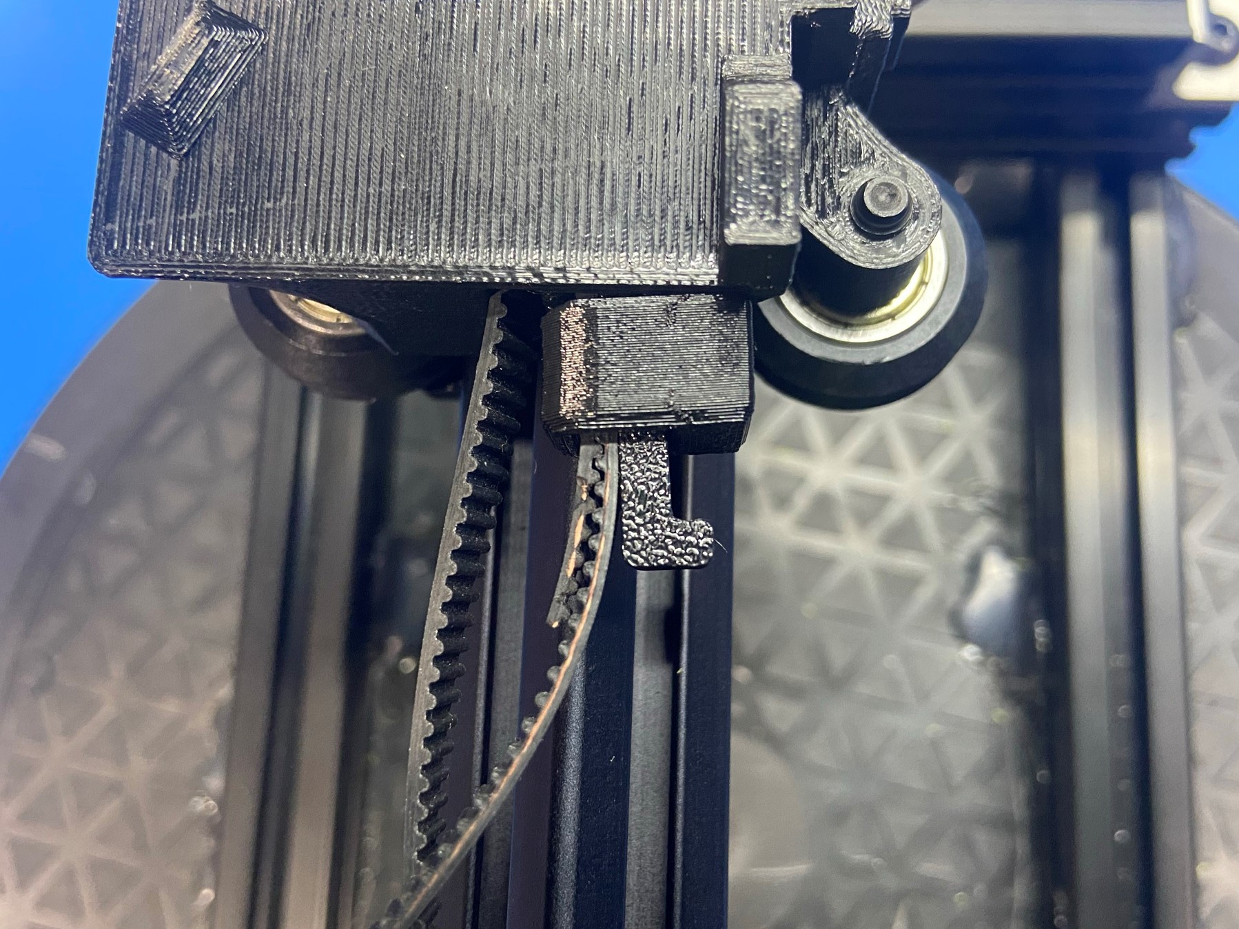
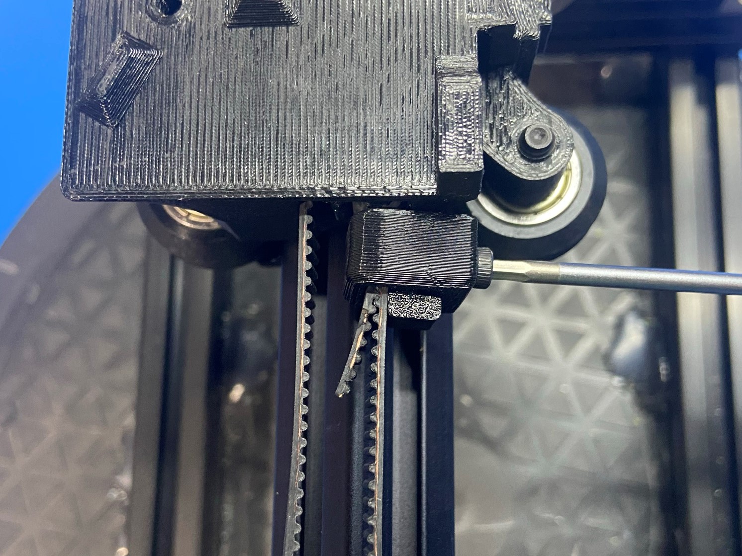
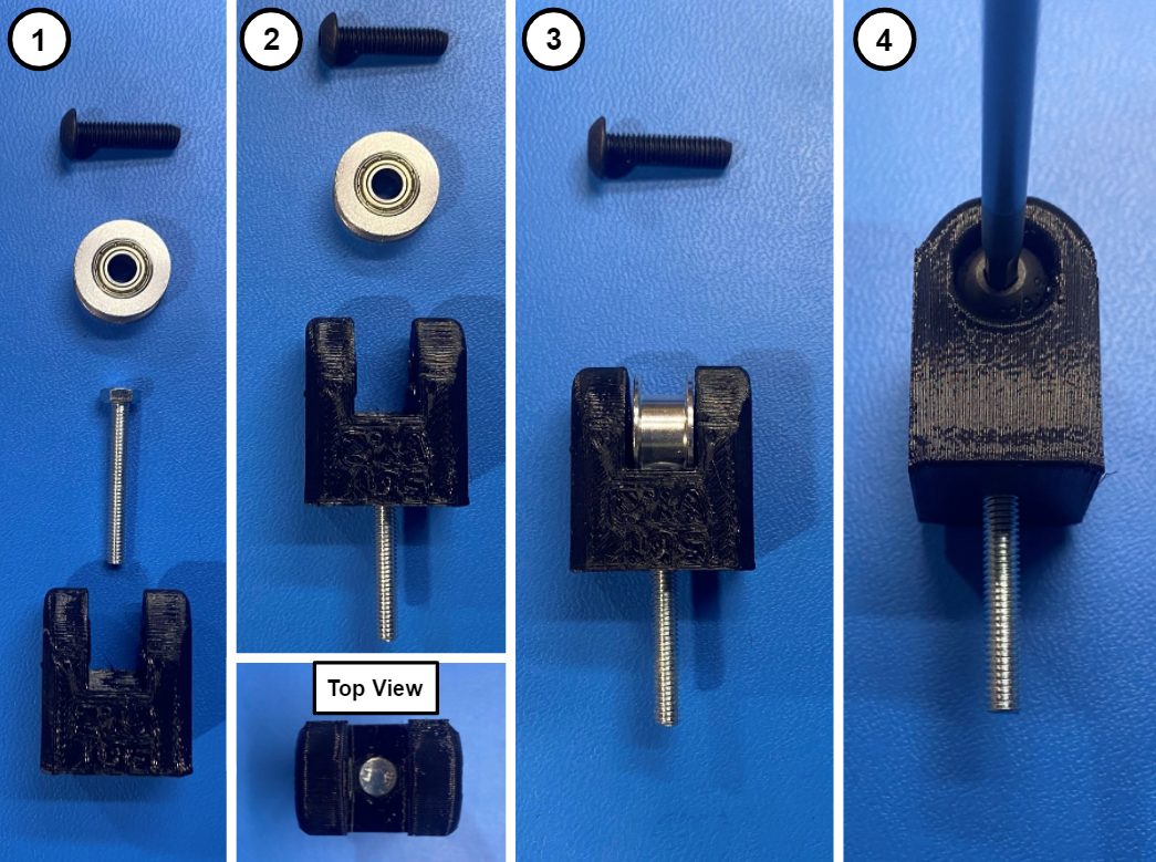
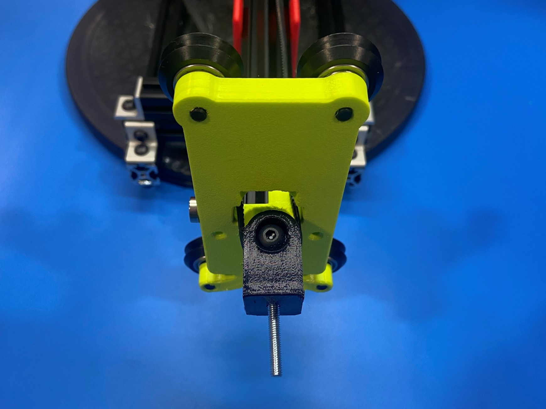
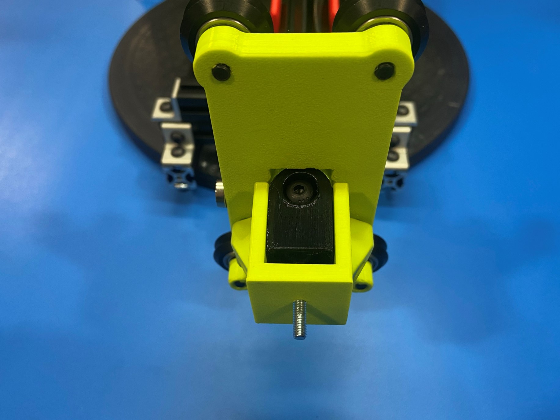
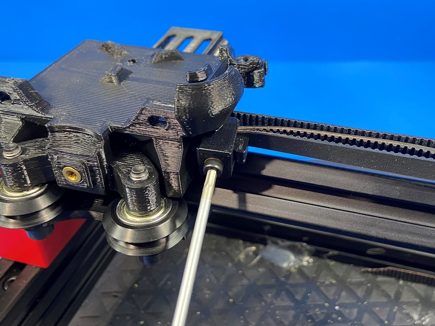
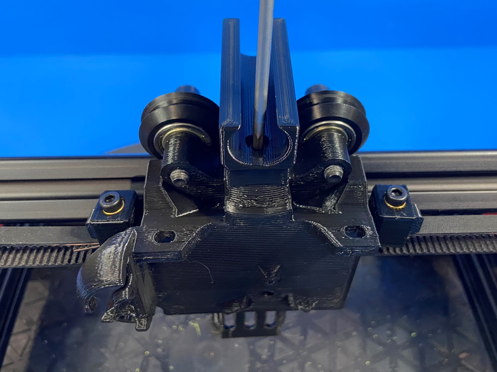
Assemble the XY belt tensioner assembly by taking 1x M4x30 HHCS [HD-BT0266] and push it through the XY belt tensioner [PP-GP0581] making sure its seated inside the hex hole. Then take 1x M5x20 BHCS [HD-BT0272] and secure the 5mm smooth bore idler in between the walls on the XY belt tensioner. [reference#2]
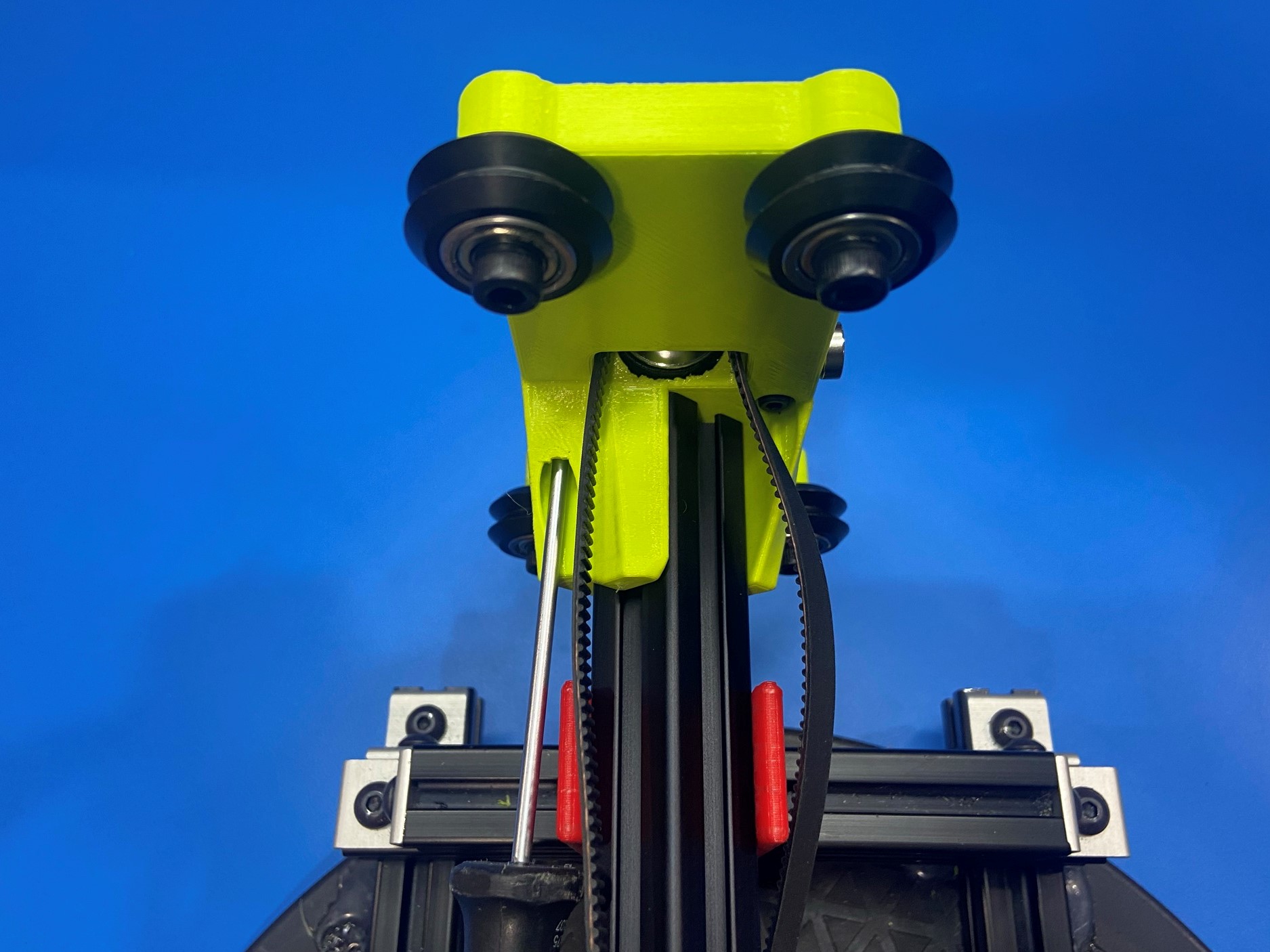
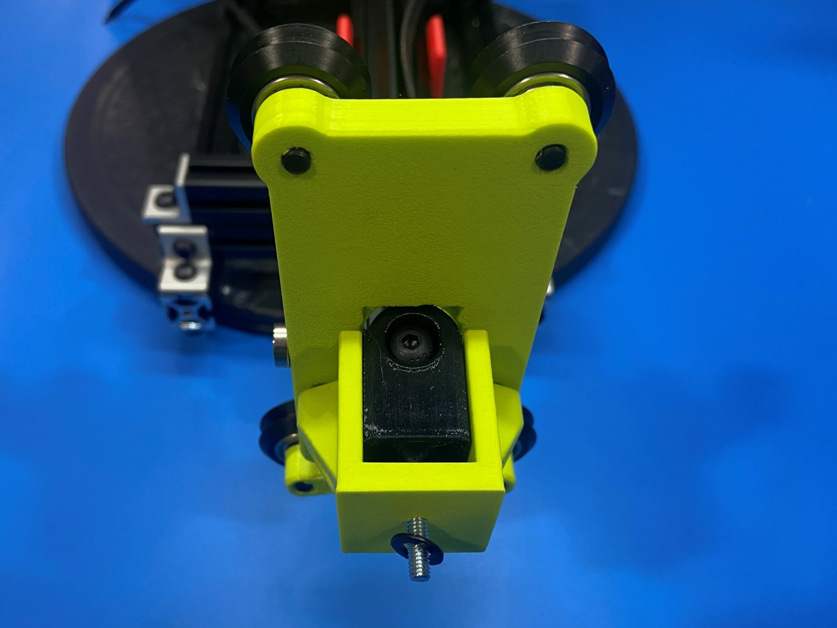
Then route the belt around the idler making sure the teeth are pointed inward. Take the X tensioner guide [PP-GP0530] and place it around the XY tensioner with [HD-BT0266] through the hole on the tensioner guide. Make sure the bolt head is on the outside.
Then using 2x M3x12 SHCS [HD-BT0039] and 2x M3 washers [HD-WA0038] attach the X tensioner guide to the X axis idler assembly.
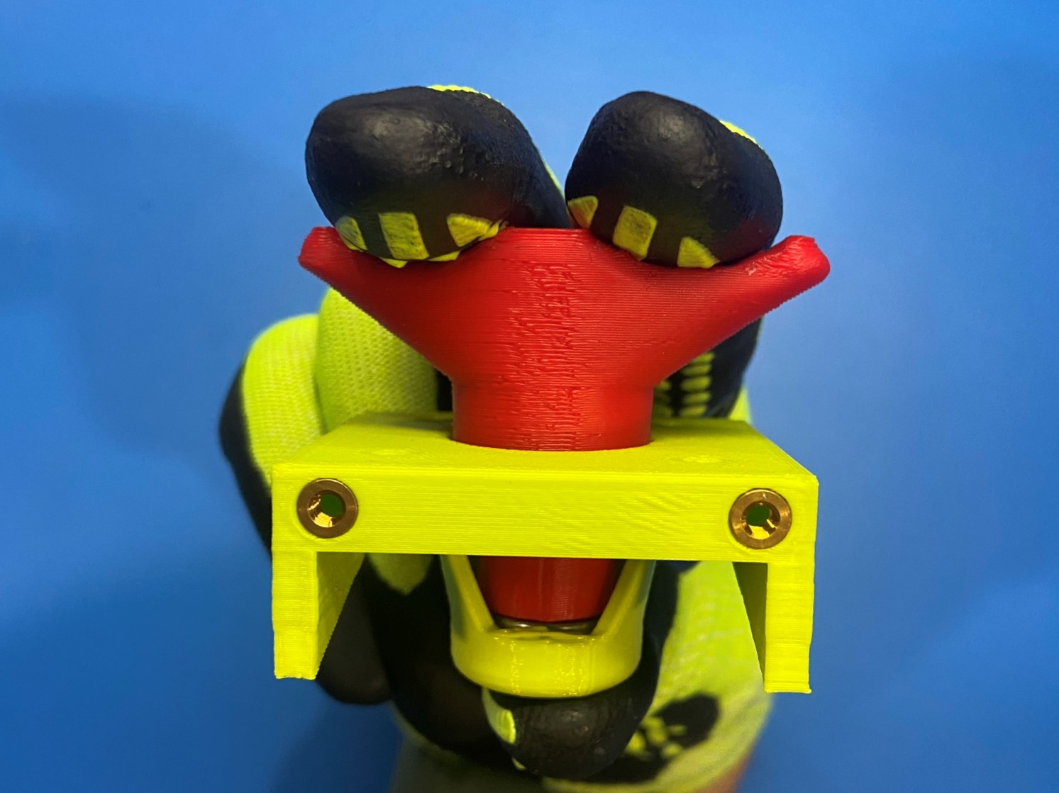
Place 1x M5 washer [HD-WA0040] around HD-BT0266 then thread the XYZ tensioner knob [PP-GP0557] making sure to leave it loose so calibration can tension the belt.
Once the belt tensioner is attached to assembly slide 1x belt clamp around the end of the belt. Then push the end of the belt through the outside hole on the X carriage assembly until it comes through the middle hole.
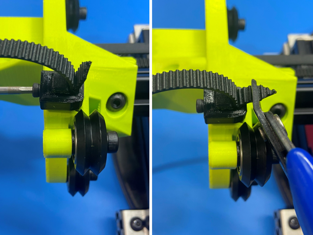
Pull on the end of the belt so all of the slack is at the end. Then slide the belt clamp around the overlapping belt and push the belt clamp sled in between the belt clamp and the belt and secure with a M3x8 SHCS [HD-BT0157].
Once the belt is attached to the X carriage cut the tails off of both ends of the belt, there should only be 3-5 teeth sticking out of the belt clamps.

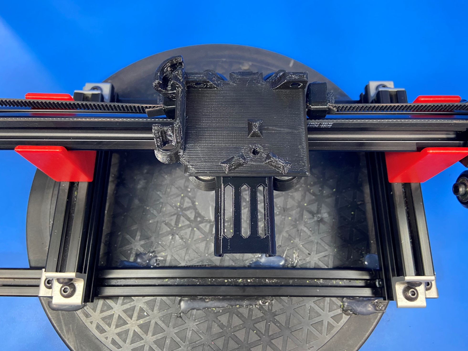
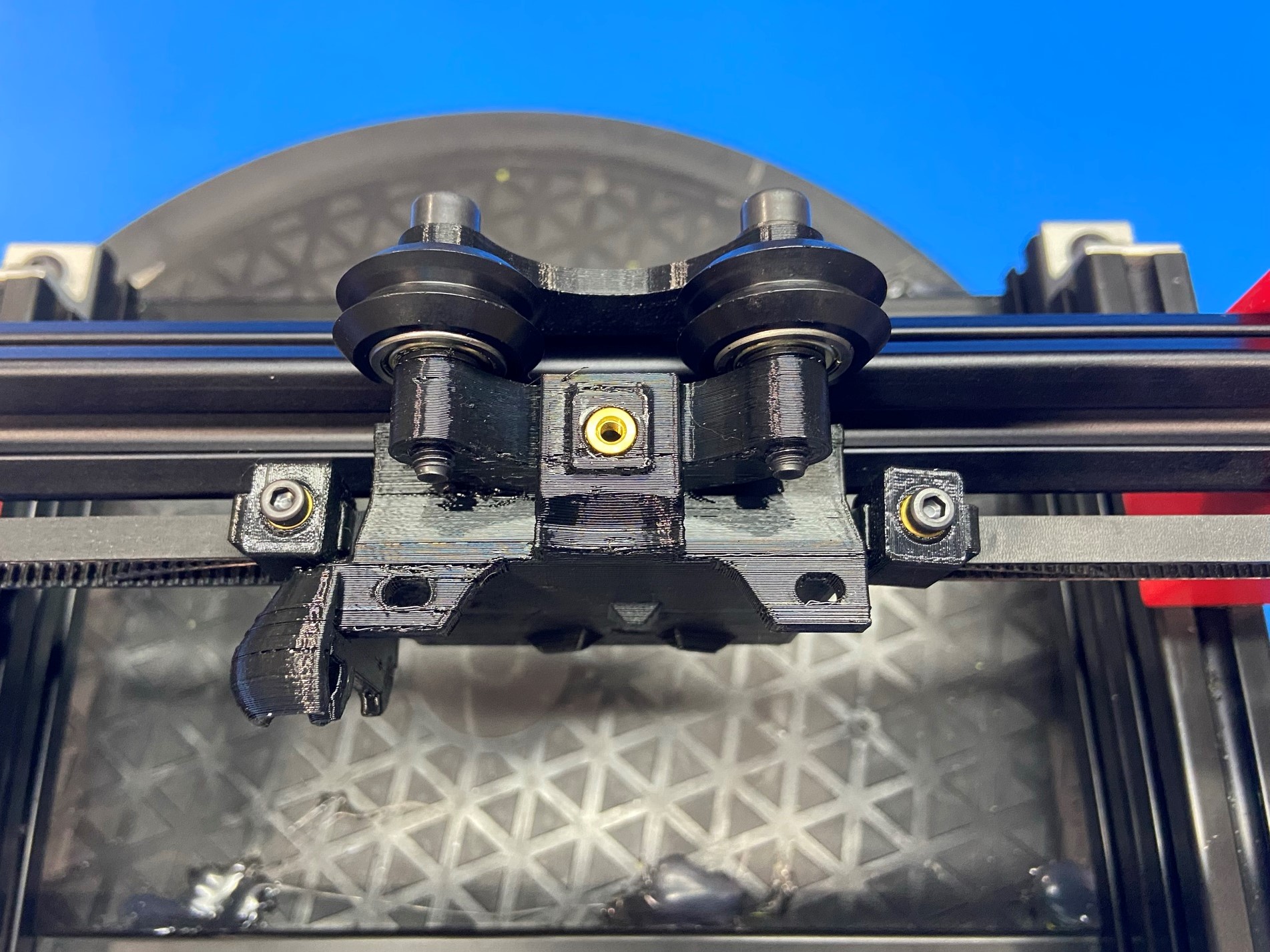
Rotate the extrusion so the top side of the X carriage is facing up. (Side with the brass insert)
Then using 1x M3x8 SHCS attach the X carriage strain relief [PP-GP0580] to the X carriage assembly.
Note: make sure the stain relief is pointed back so that its sitting between the V-wheels on the X carriage assembly.
Rotate the extrusion so the bottom side of the X carriage is facing upward.
Cut 1x single sided neoprene belt in half then trim both end to a narrow point.
Then take one end and feed it through the outside hole of the X axis idler assembly and push until the end comes through the center hole.
Slide 1x belt clamp around the overlapping belt and then slide 1x belt clamp sled between the belt clamp and the belt and secure with 1x M3x8 SHCS. Then trim the belt so the end is a straight line.
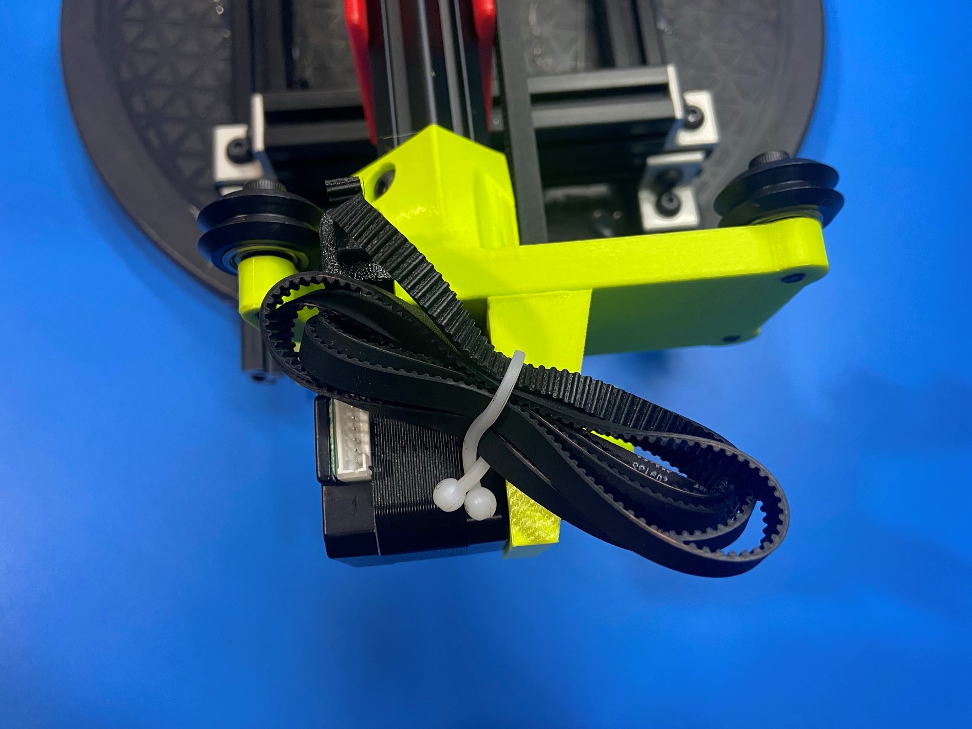
Once the belt is attached to the X axis idler wrap the belt up and place a reusable clip around the middle of the bundle and then twist the end so that the clip is locked in place.
Repeat the following instructions for the X motor assembly