Open HardwareAssembly Instructions
Guides for installation and assembly of the LulzBot line of products made by FAME 3D LLC.
Guides for installation and assembly of the LulzBot line of products made by FAME 3D LLC.
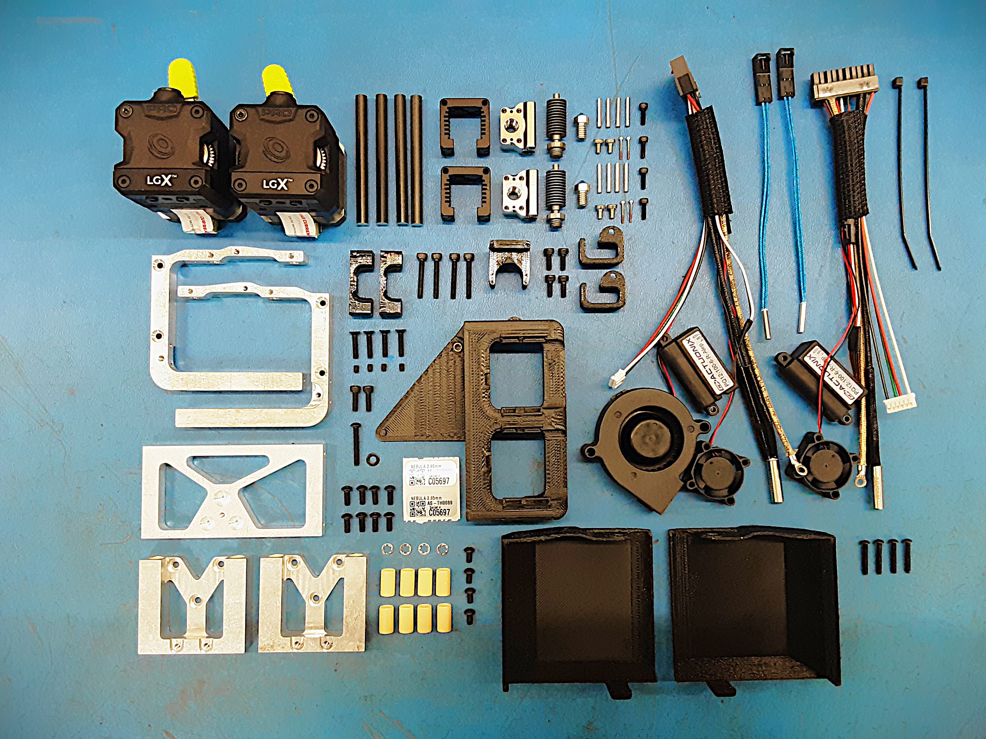
Twin Nebula Shared Parts:
1x [AS-CB0210] Twin Nebula E0 Wire Harness
1x [AS-CB0211] Twin Nebula E1Wire Harness
2x [DC-LB0160] Tool Head Serial Number Sticker, Matte Silver, 1" x 0.5", Thermal
2x [EL-TH0015] 104GT Thermistor 100mm leads
2x [HD-BT0005] M3 x 10 Bolt, SHCS Black-Oxide
4x [HD-BT0007] M3 x 20 Bolt, SHCS Black-Oxide
4x [HD-BT0118] M3 x 14 Bolt FHCS, Black-Oxide
8x [HD-BT0137] M3 x 8 Bolt, BHCS, Black Oxide
4x [HD-BT0140] M3 x 6 Bolt, BHCS Black Oxide
4x [HD-BT0157] Class 12.9 Alloy Steel Black-Oxide SHCS, M3 x 8mm Length, 0.50mm Pitch
4x [HD-BT0162] Alloy Steel Cup Point Set Screw, M3 x 4mm Long, 0.5mm Pitch
1x [HD-BT0171] Class 10.9 Black-Oxide Steel BHCS M3 x 20mm Length, .5mm Pitch
4x [HD-BT0261] Black-Oxide BHCS, M2.5 x 16mm Length
4x [HD-BT0284] M2.5 x 8mm SHCS Black Oxide Finish
2x [HD-MS0100] Hot Block Hardware Kit, Standard
8x [HD-MS0480] iglide J, sleeve bearing, mm
4x [HD-RD0070] 6mm Smooth Rod, Aluminum, 65mm
4x [HD-WA0027] Metric 18-8 Stainless Steel Internal-Tooth Lock Washer, M3 Size, 6MM OD
1x [HD-WA0038] Black-Oxide 18-8 Steel Flat Washer, M3 Screw Size, 3.2mm ID, 7.0mm OD
2x [PP-FP0244] LGX Servo Slide
2x [PP-FP0245] Servo Slide Mount
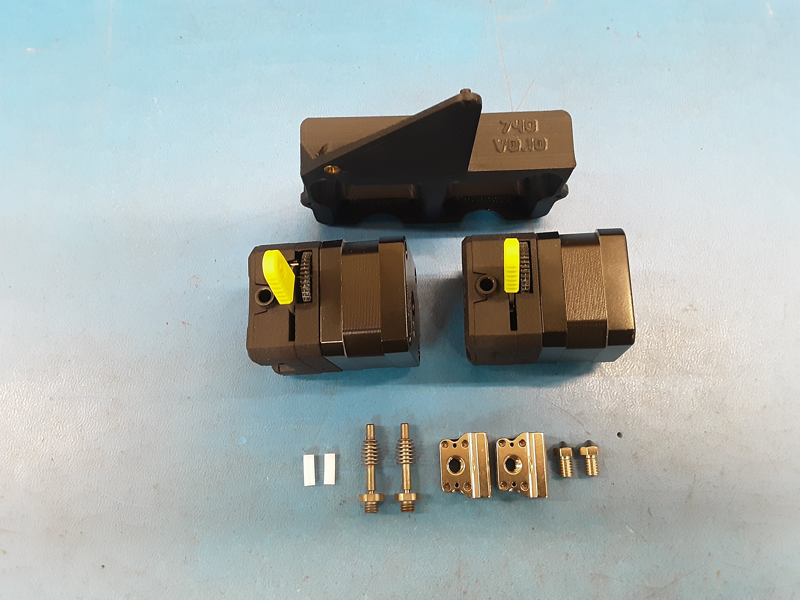
1x [PP-FP0246] TAZ Pro Dual LGX Base
2x [PP-MP0345] Mosquito Heat Sink
1x [PP-GP0741] Twin Nebula Servo Cover, Right
1x [PP-GP0742] Twin Nebula Servo Cover, Left
2x [PP-GP0743] Twin Nebula Servo Wire Hoop
1x [PP-GP0744] Twin Nebula Bump Stop
2x [PP-GP0746] Twin Nebula Hot End Wire Strap
Twin Nebula 285 Specific Parts:
2x [PP-MP0336] LGX Extruder, 2.85mm, LGX PRO Lulzbot Edition
2x [PP-MP0338] Mosquito Hot Block, 2.85mm, Non-Retail
2x [PP-MP0352] Heat Break, Mosquito 2.85mm, Standard
2x [PP-MP0416] Micro Swiss, Nickel Plated Brass Nozzle - 2.85mm x 0.5mm
1x [PP-GP0764] Twin Nebula Blower Shroud, 2.85MM
Twin Nebula 175 Specific Parts:
22mm [HD-TB0080] Feed Tube, 2mm ID X 4mm OD NAT PTFE Tube
2x [PP-MP0335] LGX Extruder, 1.75mm, LGX PRO Lulzbot Edition
2x [PP-MP0337] Mosquito Hot Block,1.75mm
2x [PP-MP0412] Micro Swiss, Nickel Plated Brass Nozzle - 1.75mm x 0.5mm
2x [PP-MP0504] Heat Break, Mosquito 1.75mm, Standard
1x [PP-GP0740] Twin Nebula Blower Shroud, 1.75MM
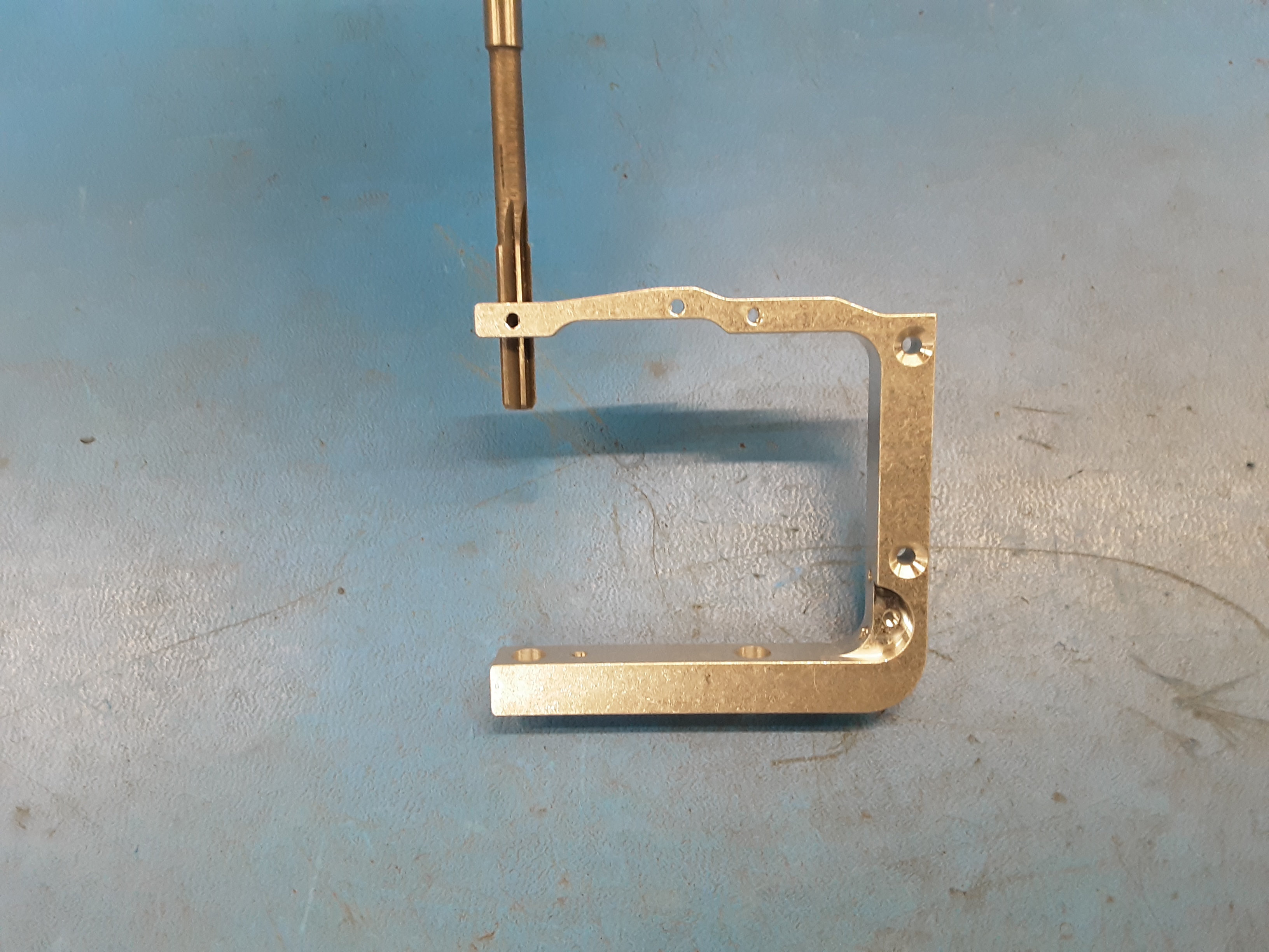
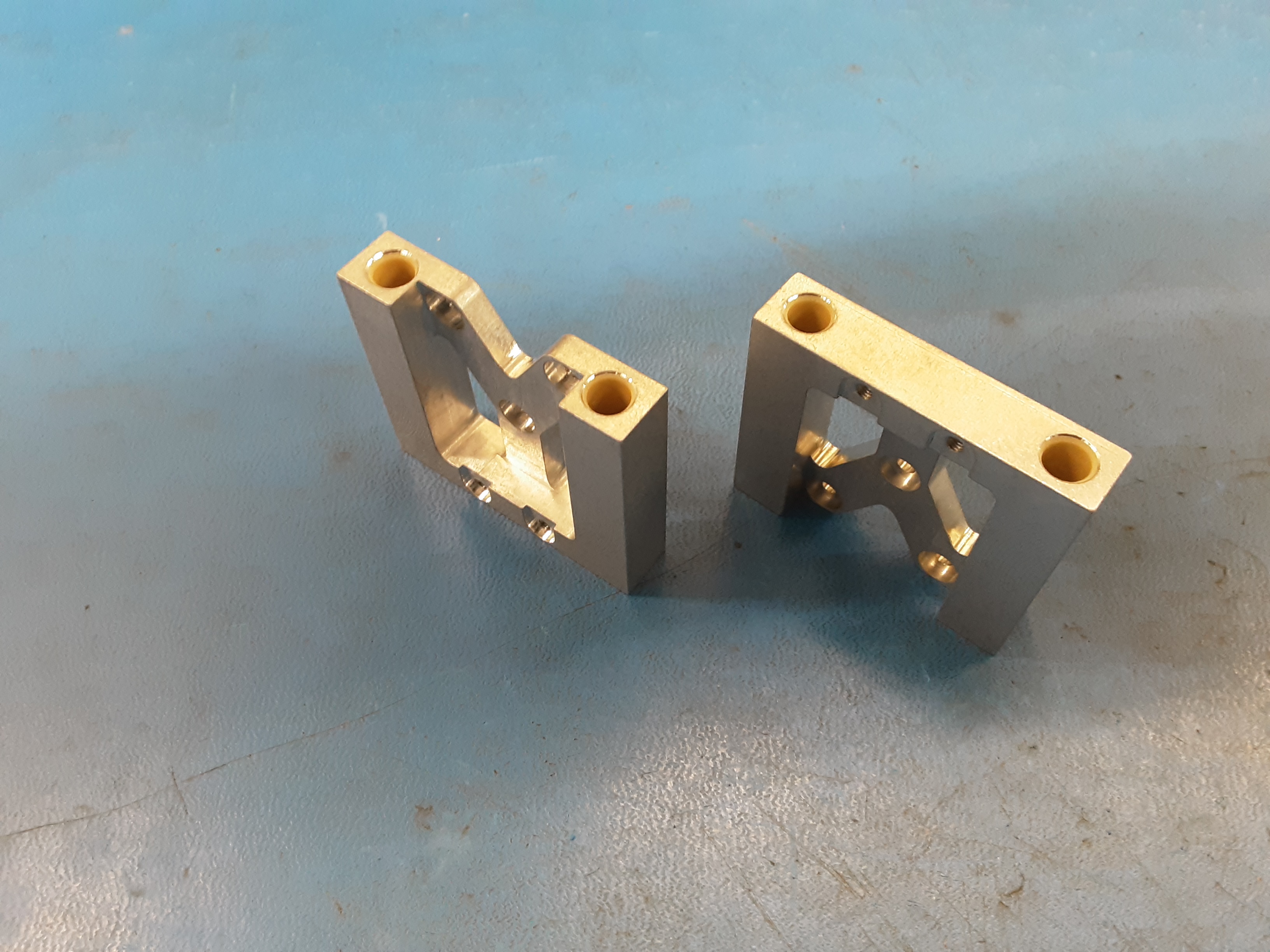
2A) Using a 6mm ream take 2x PP-FP0245 and clean out the four holes where HD-RD0070 goes on both parts.
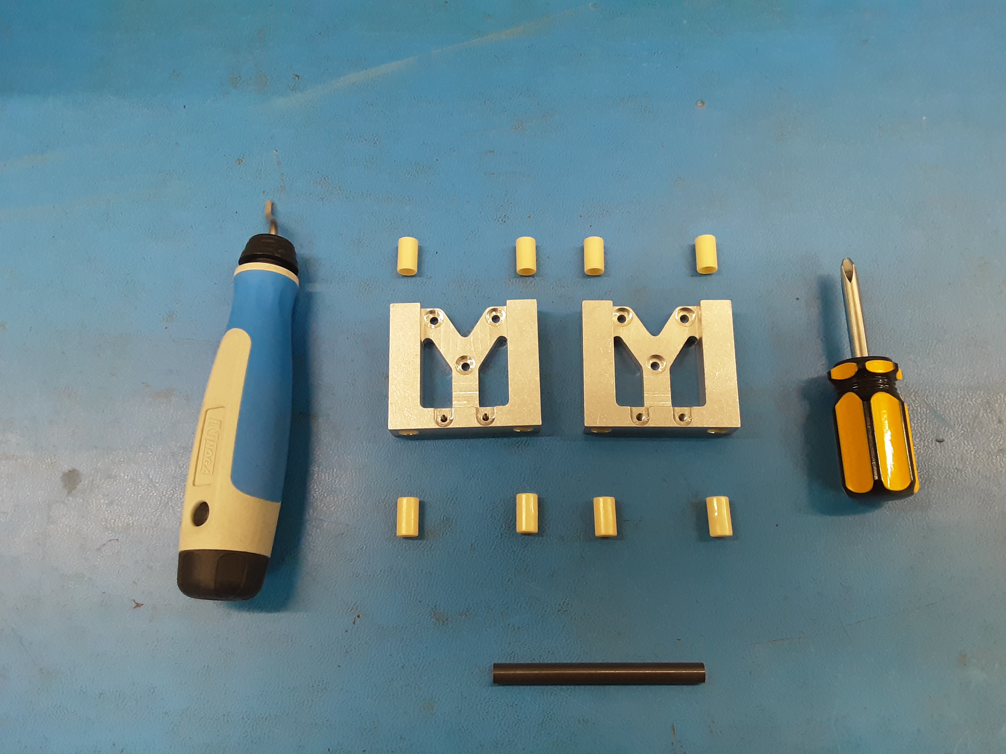
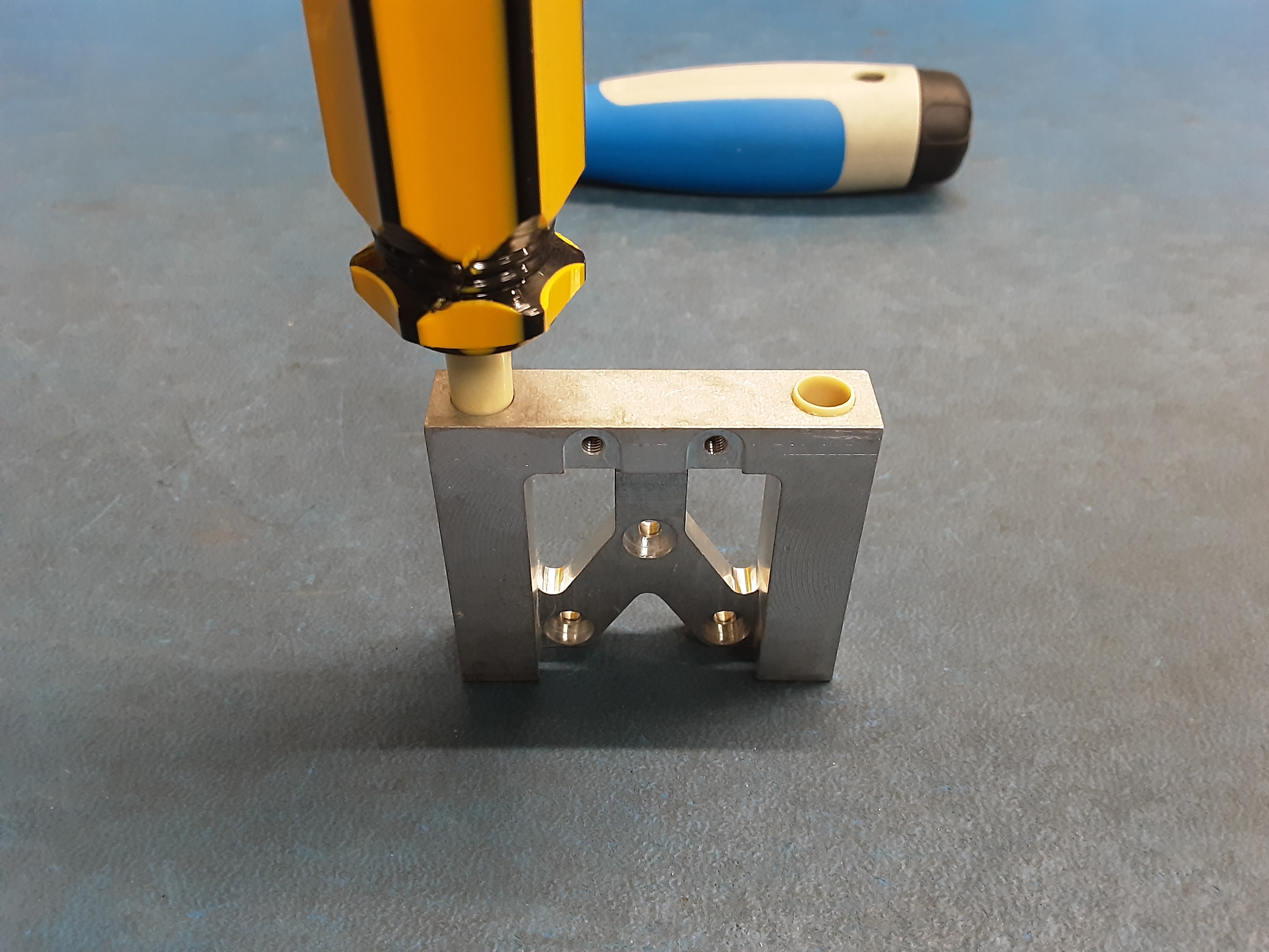
2B) Grab 2x PP-FP0244, 8x HD-MS0480, and 1x HD-RD0070. Also grab the screwdriver and deburring tool located in the HD-MS0480 bin.
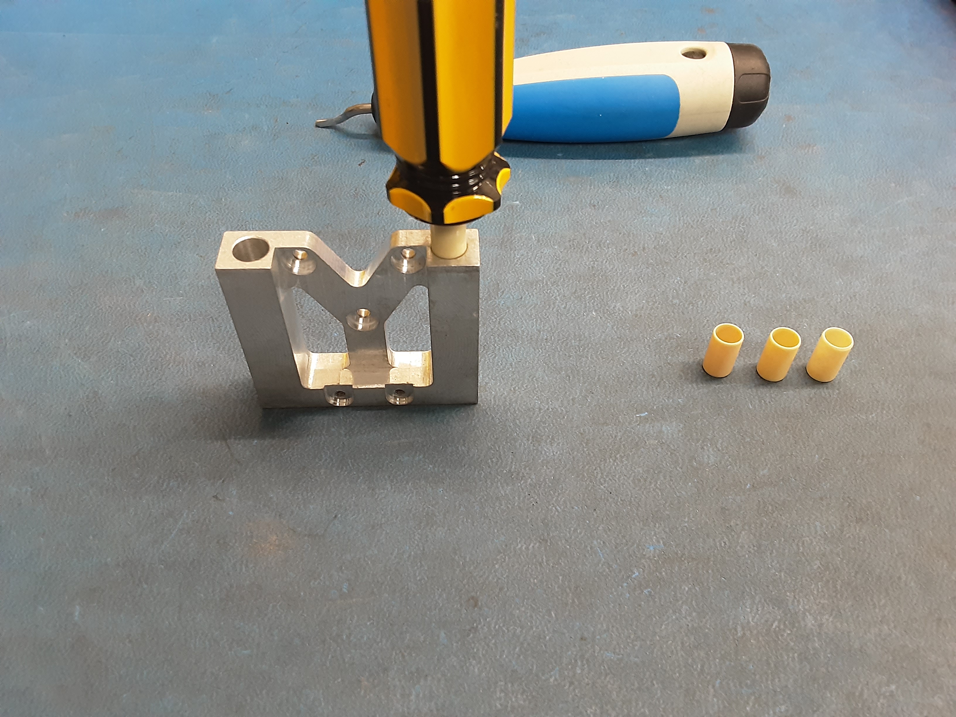
2C) Using the screwdriver insert HD-MS0480 into the top halves of PP-FP0244.
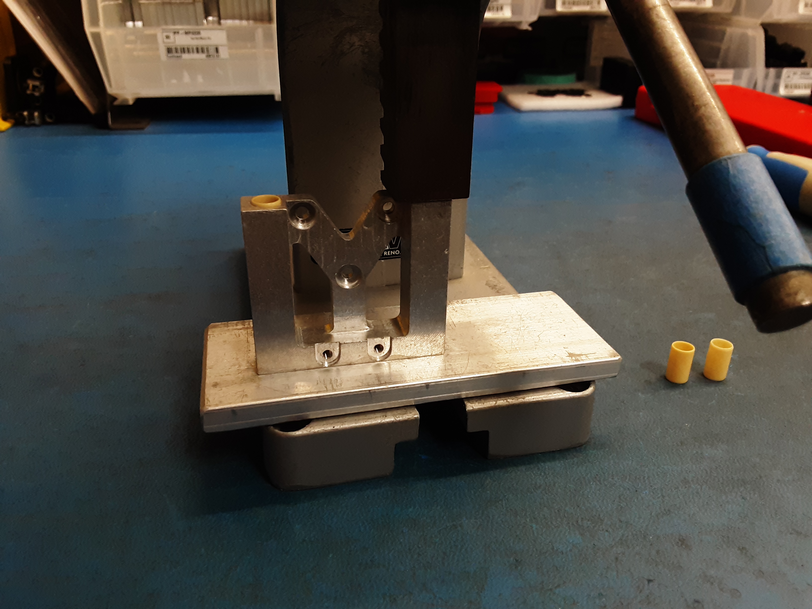
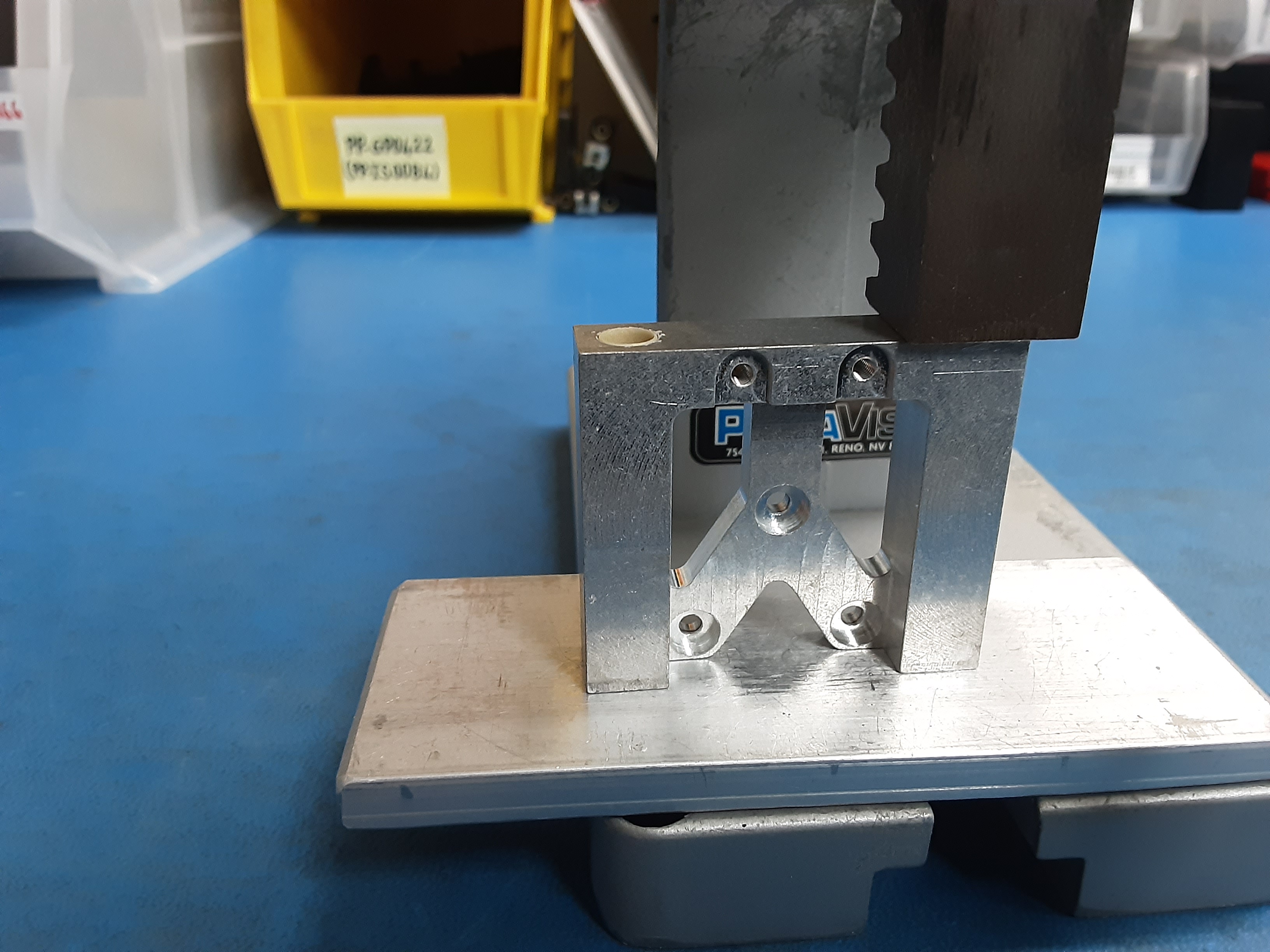
2D) Use the arbor press to push the bushings in the rest of the way.
2E) Flip 2x PP-FP0244 over and use the screwdriver to insert HD-MS0480 into the bottom halves.
2F) Use the arbor press to push the bushings in the rest of the way.
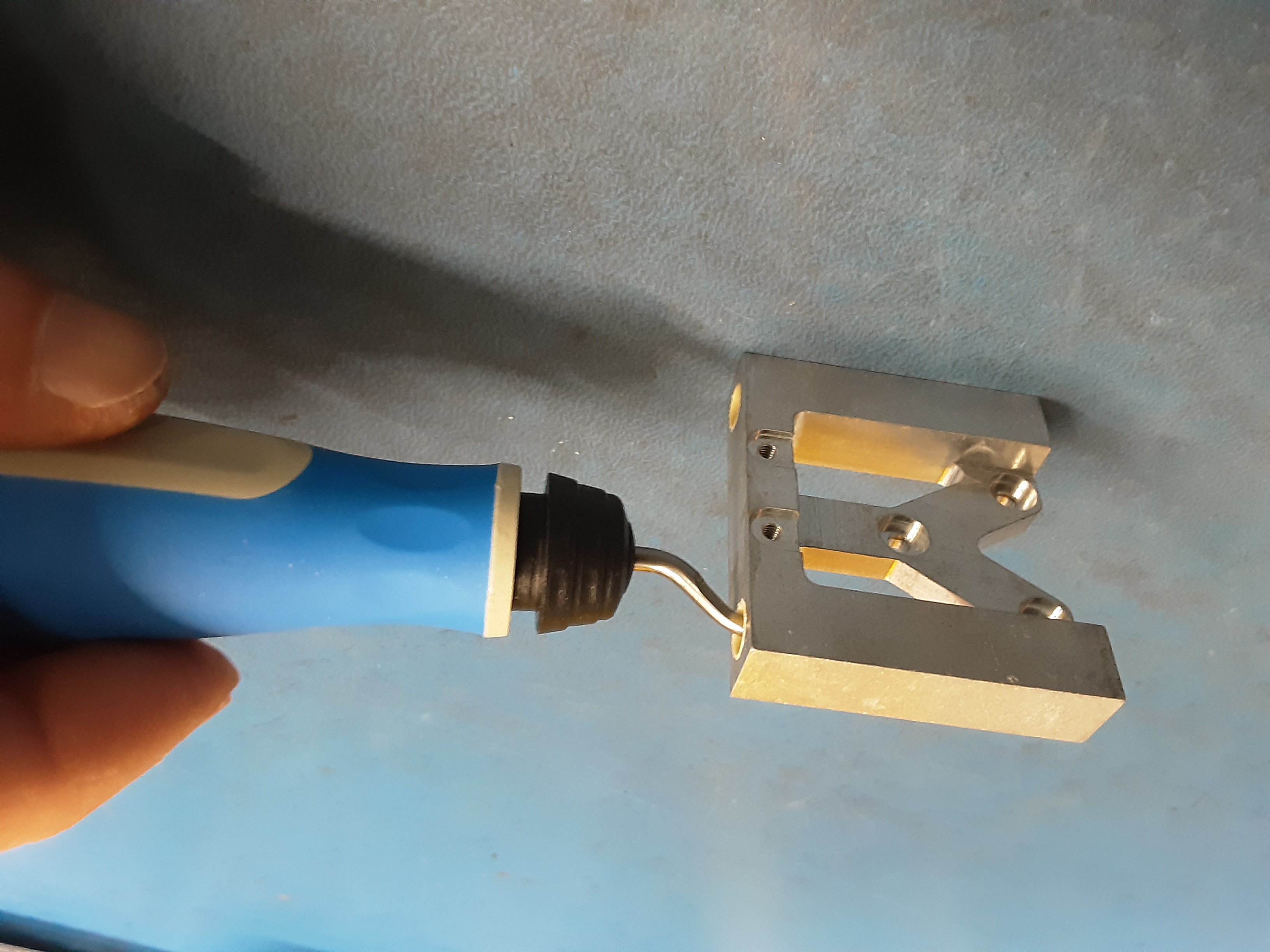
2G) Use the deburring tool to clean up the edges.
2H) Using HD-RD0070 test the bushing. The rod should just fall through the holes.
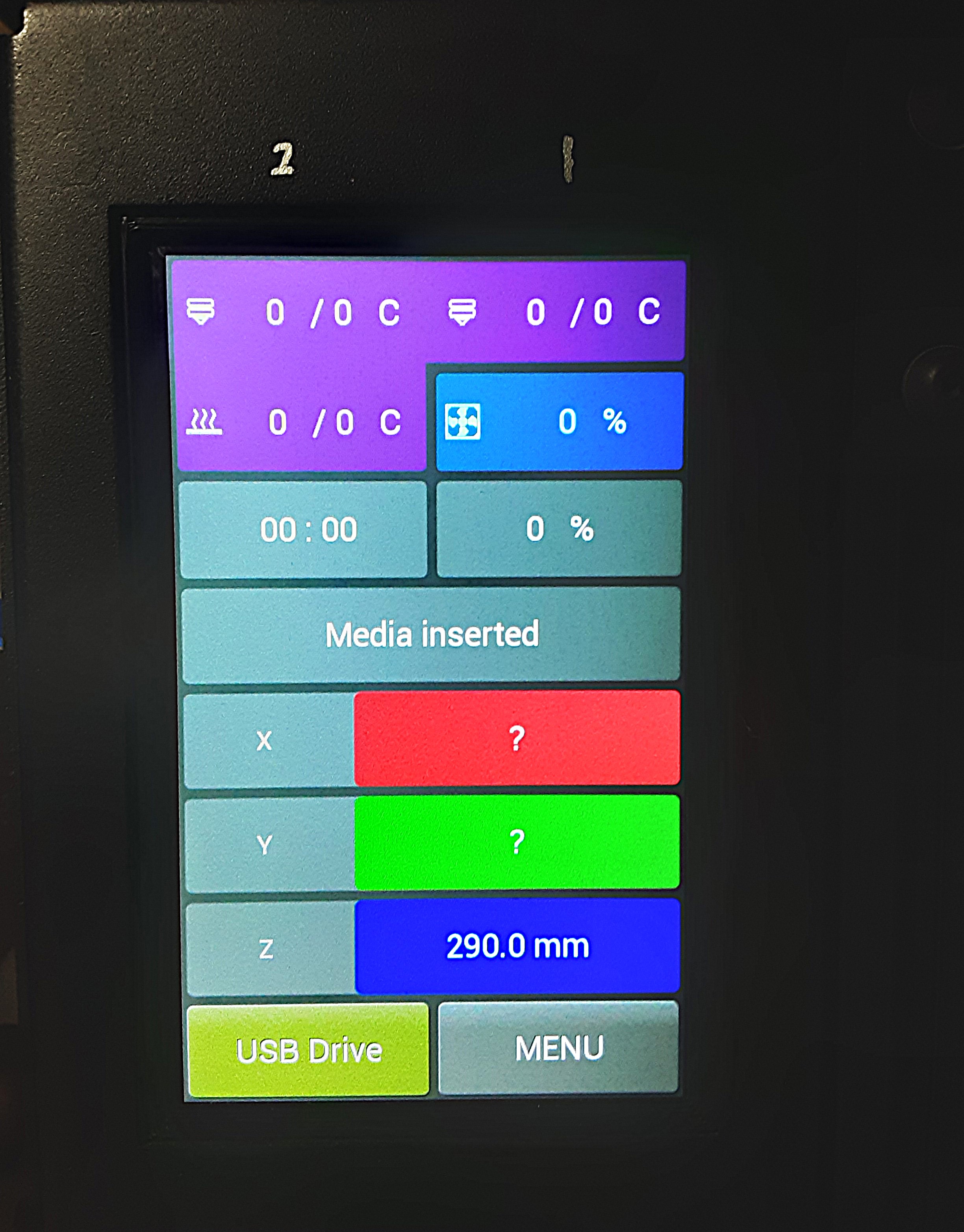
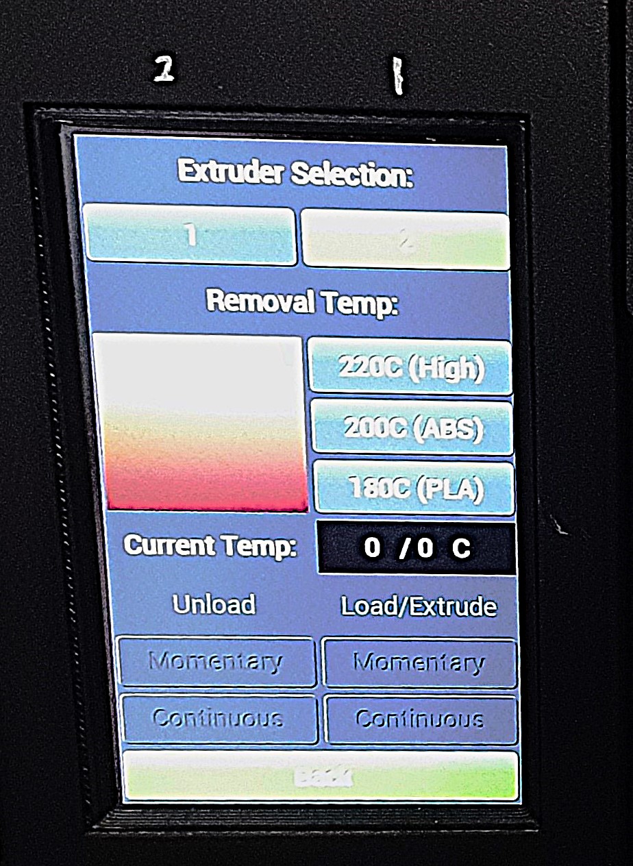
3A) Turn on test printer and select “Menu”
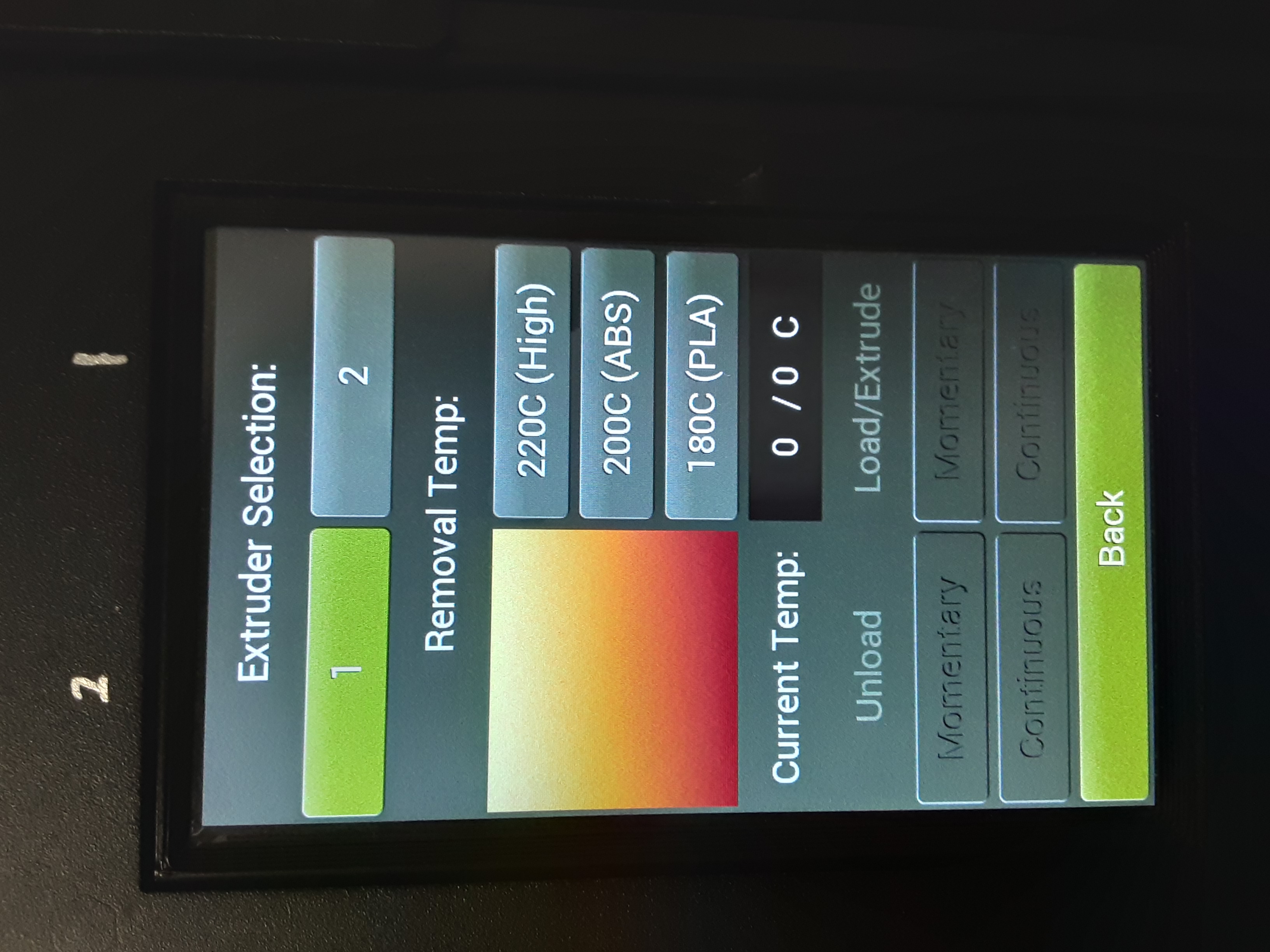
3B) Select “Change Filament”
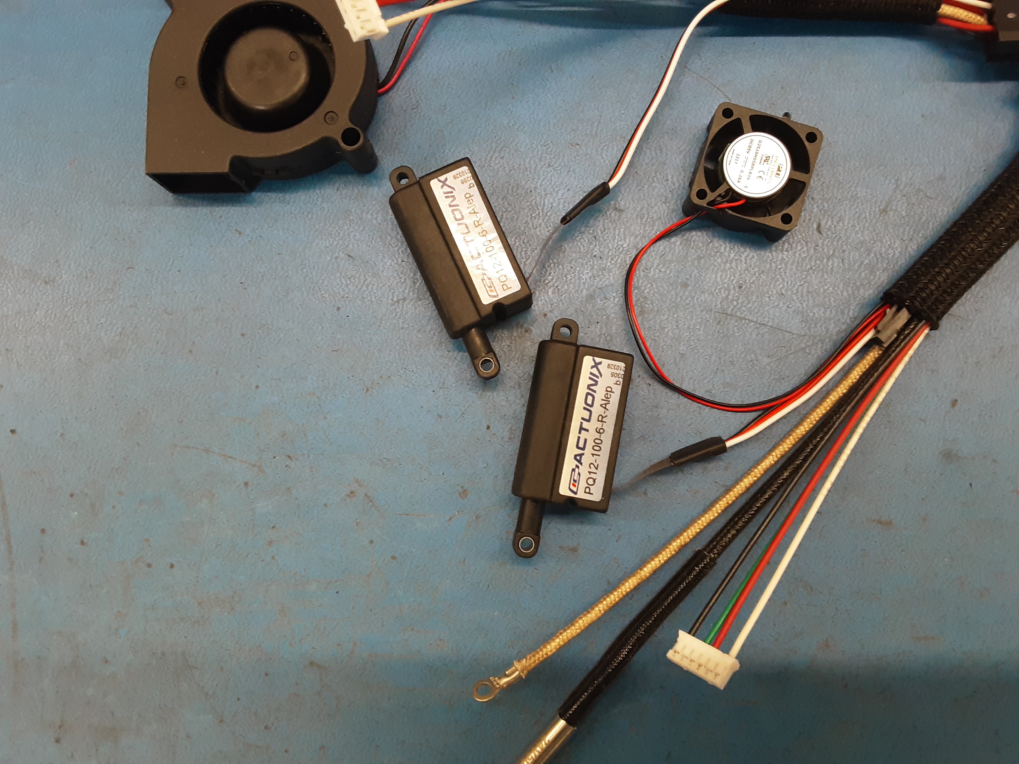
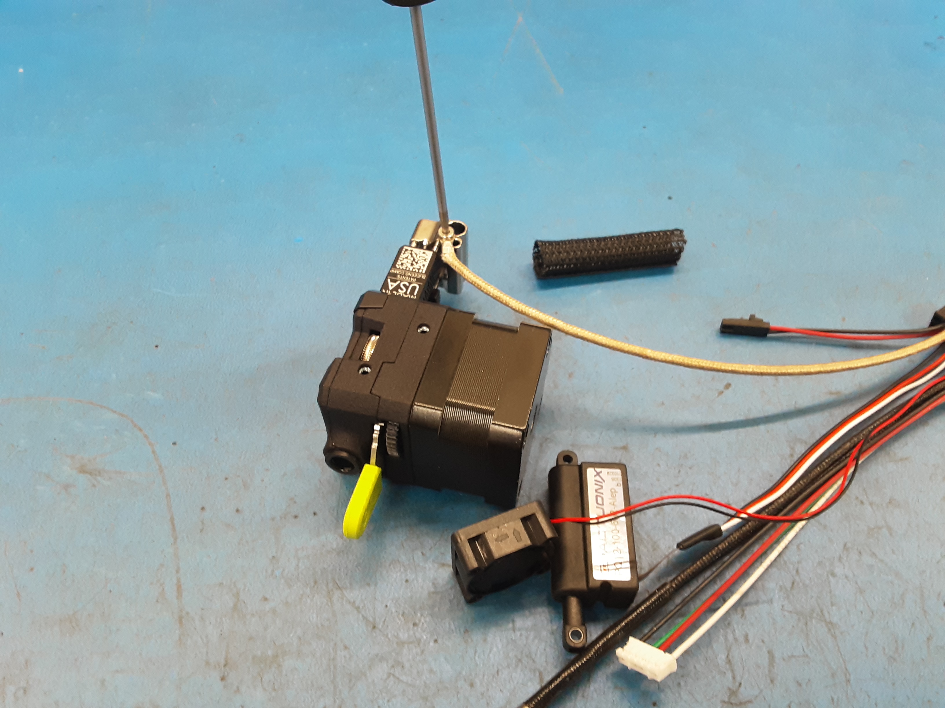
3C) With “1” selected plug in AS-CB0211 to extend the actuator.
3D) Select “2” and plug in AS-CB0210 to extend the actuator.
3E) Both actuators should now be slightly extended.


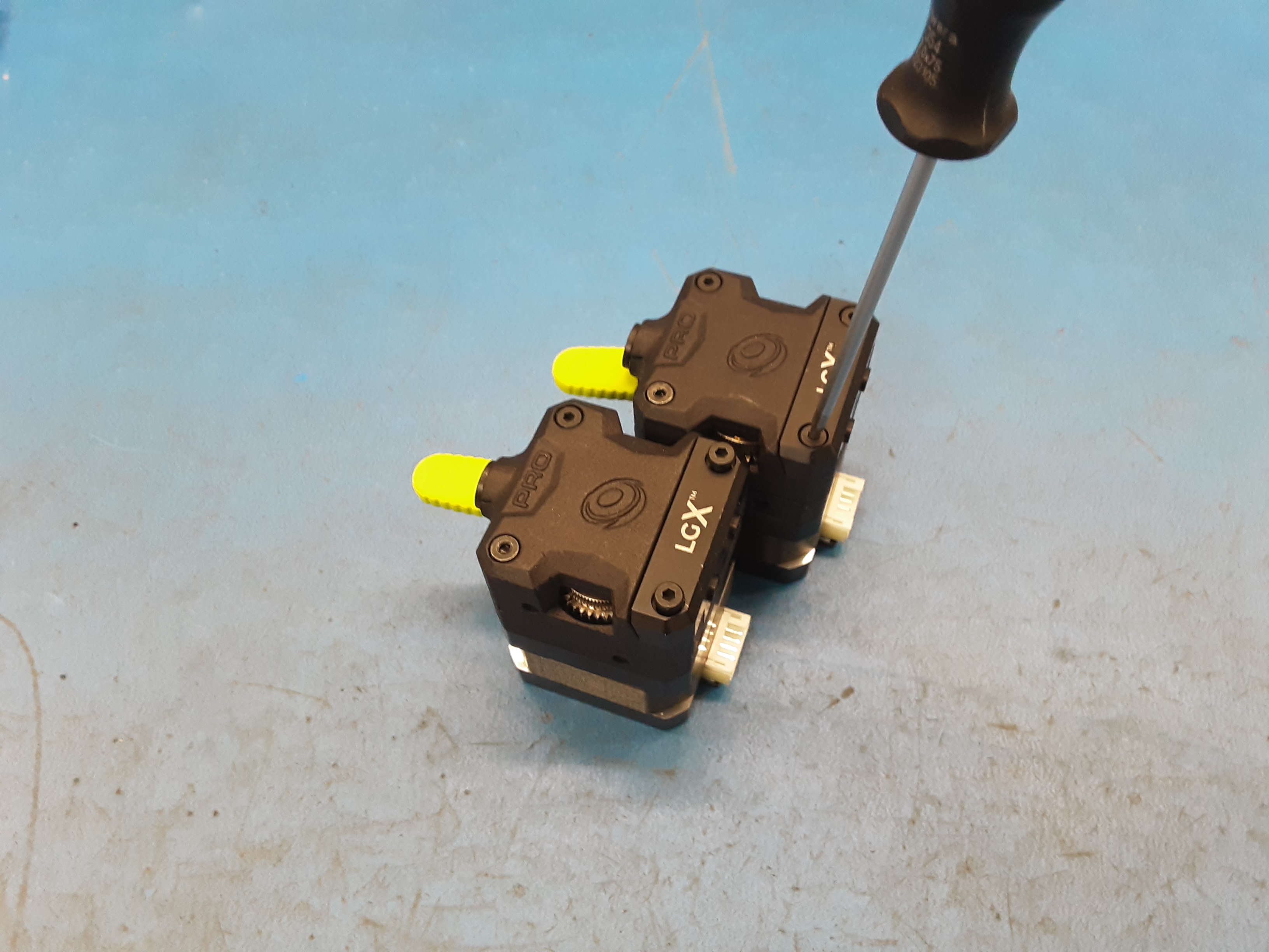
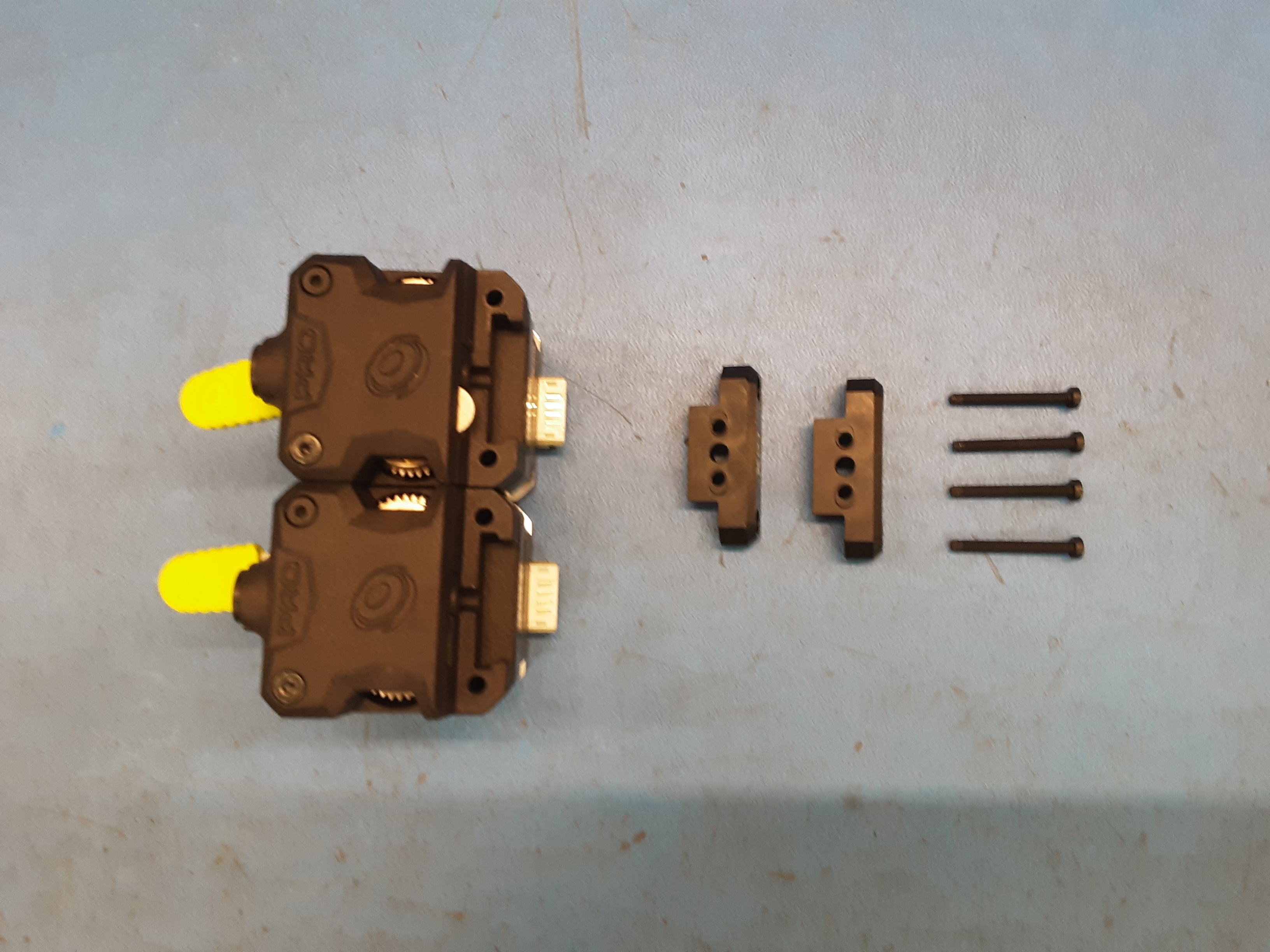
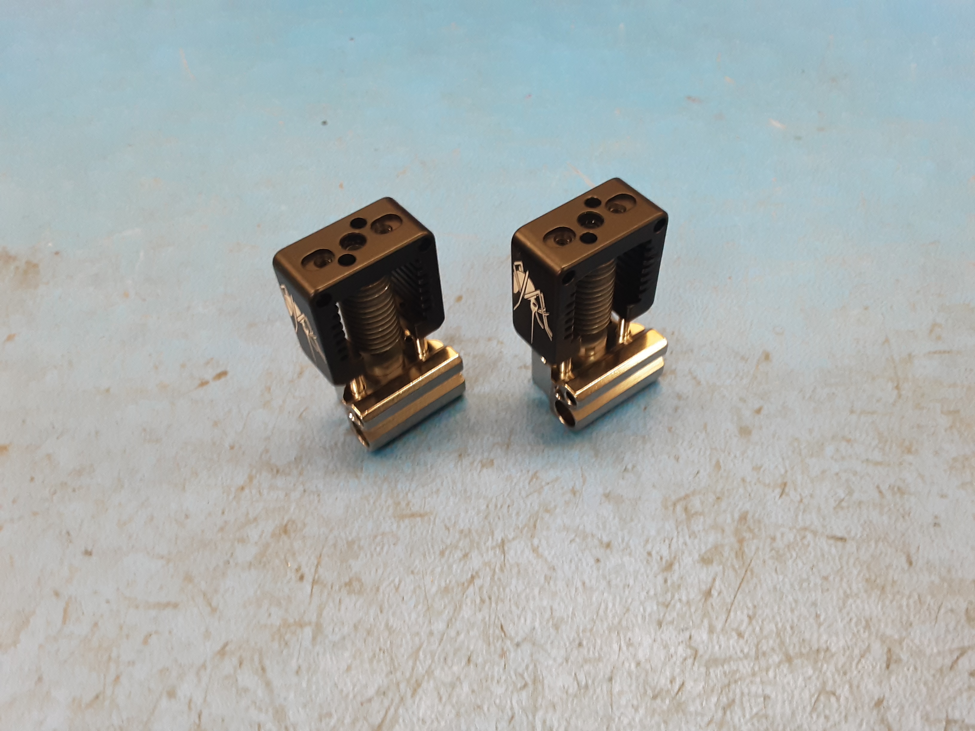
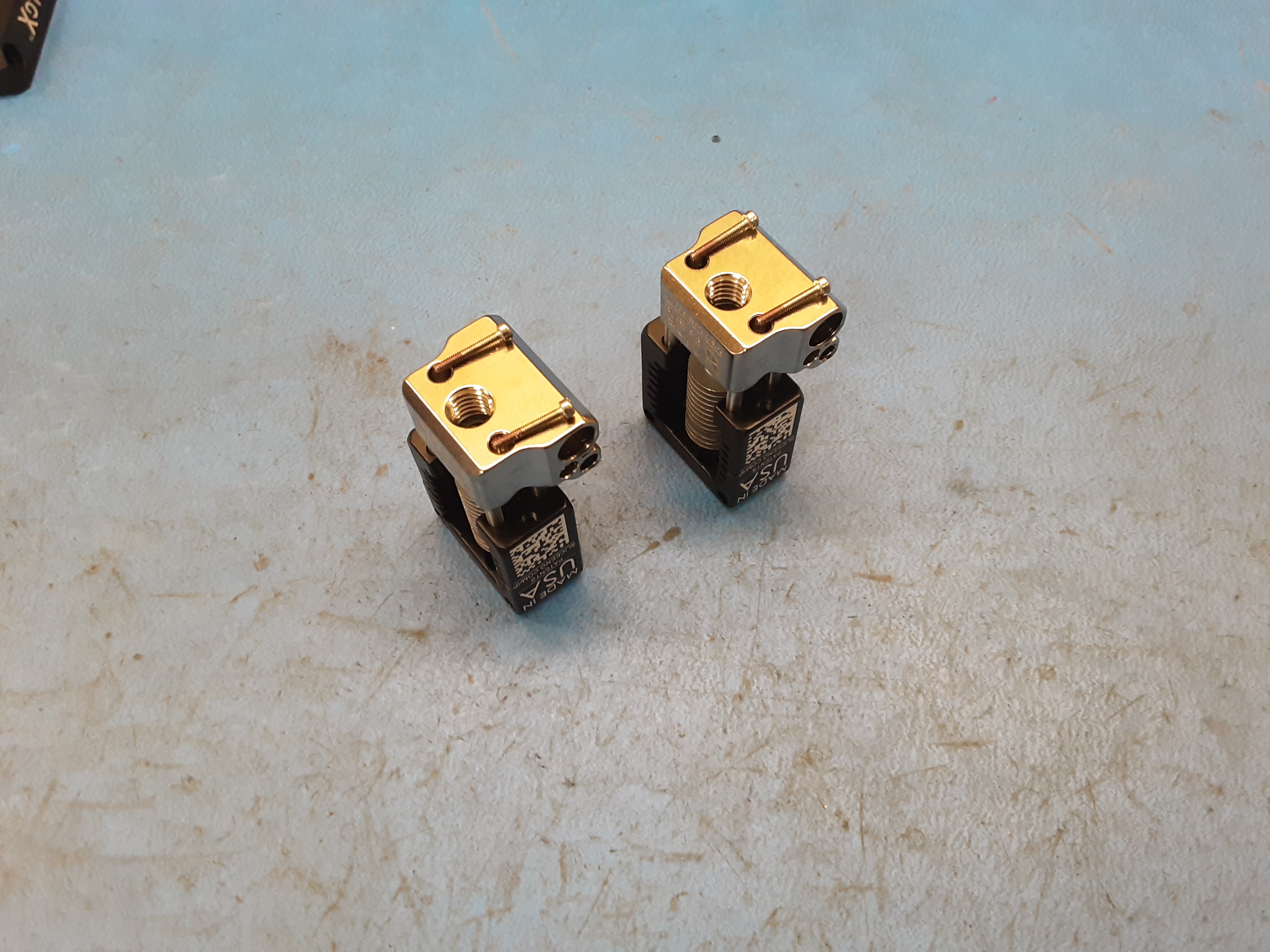
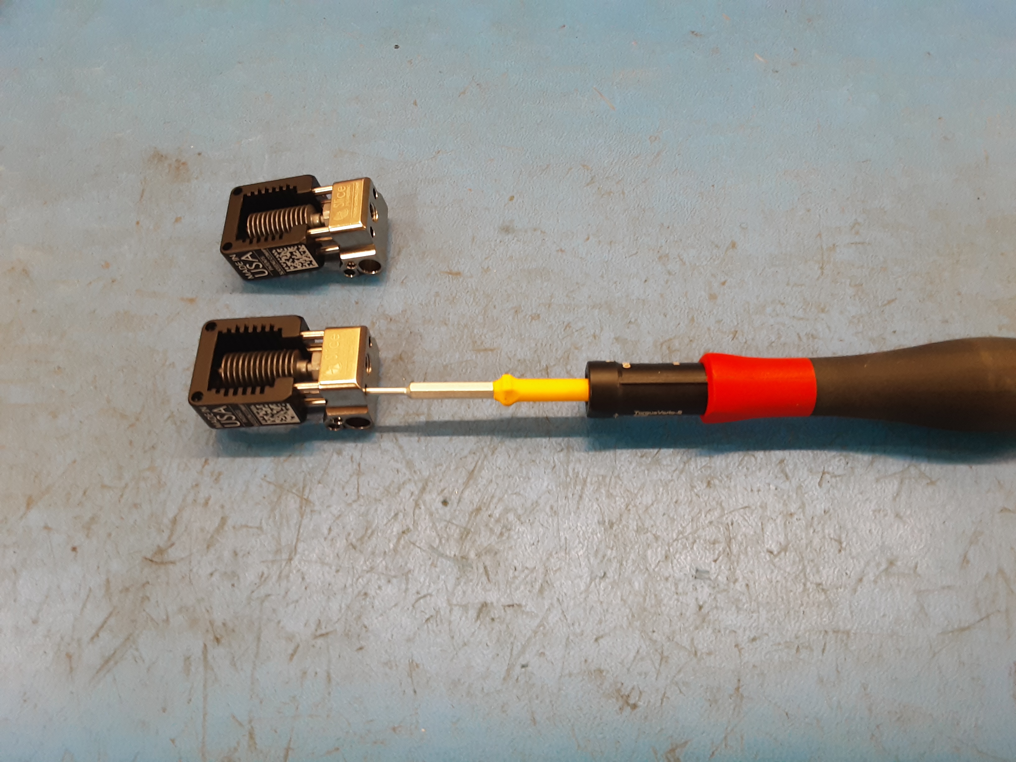
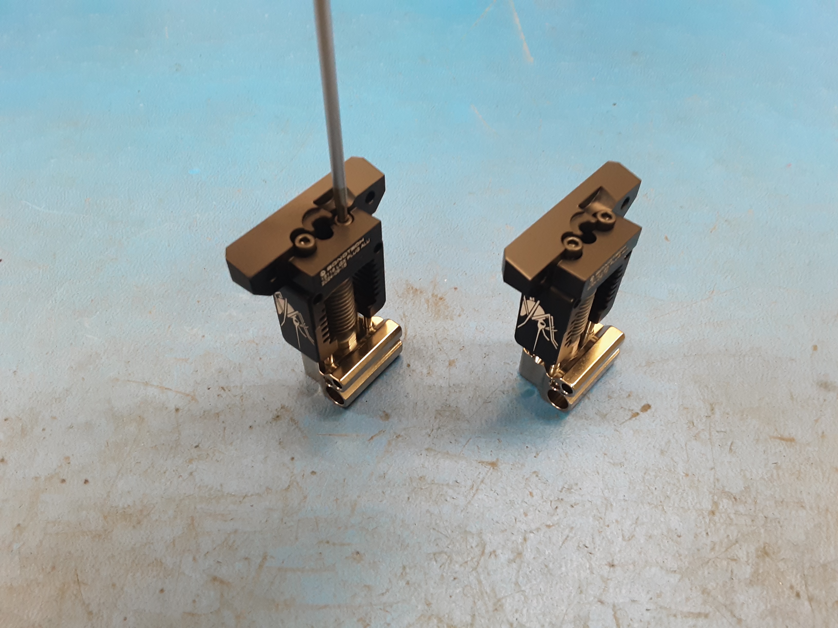
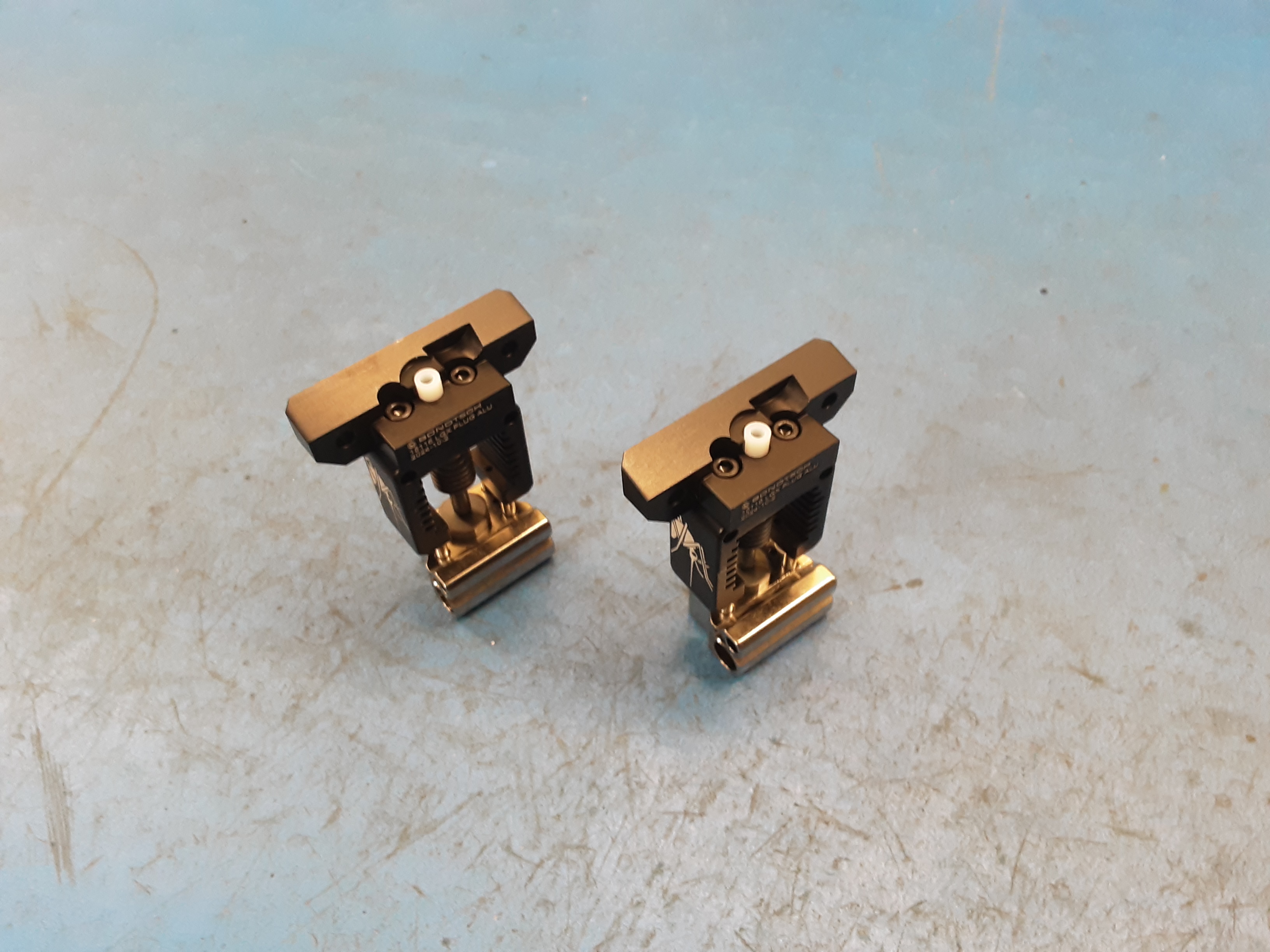
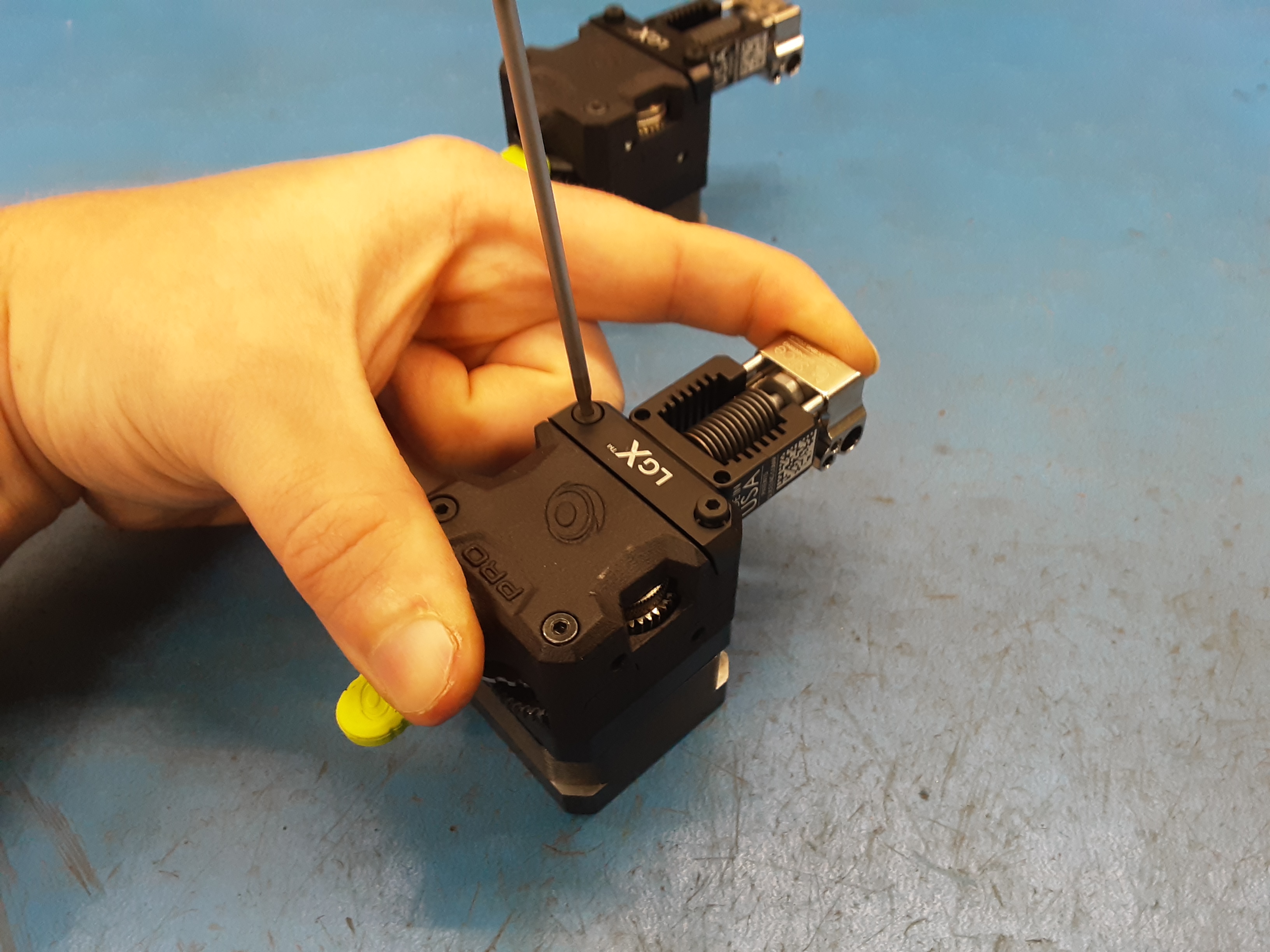
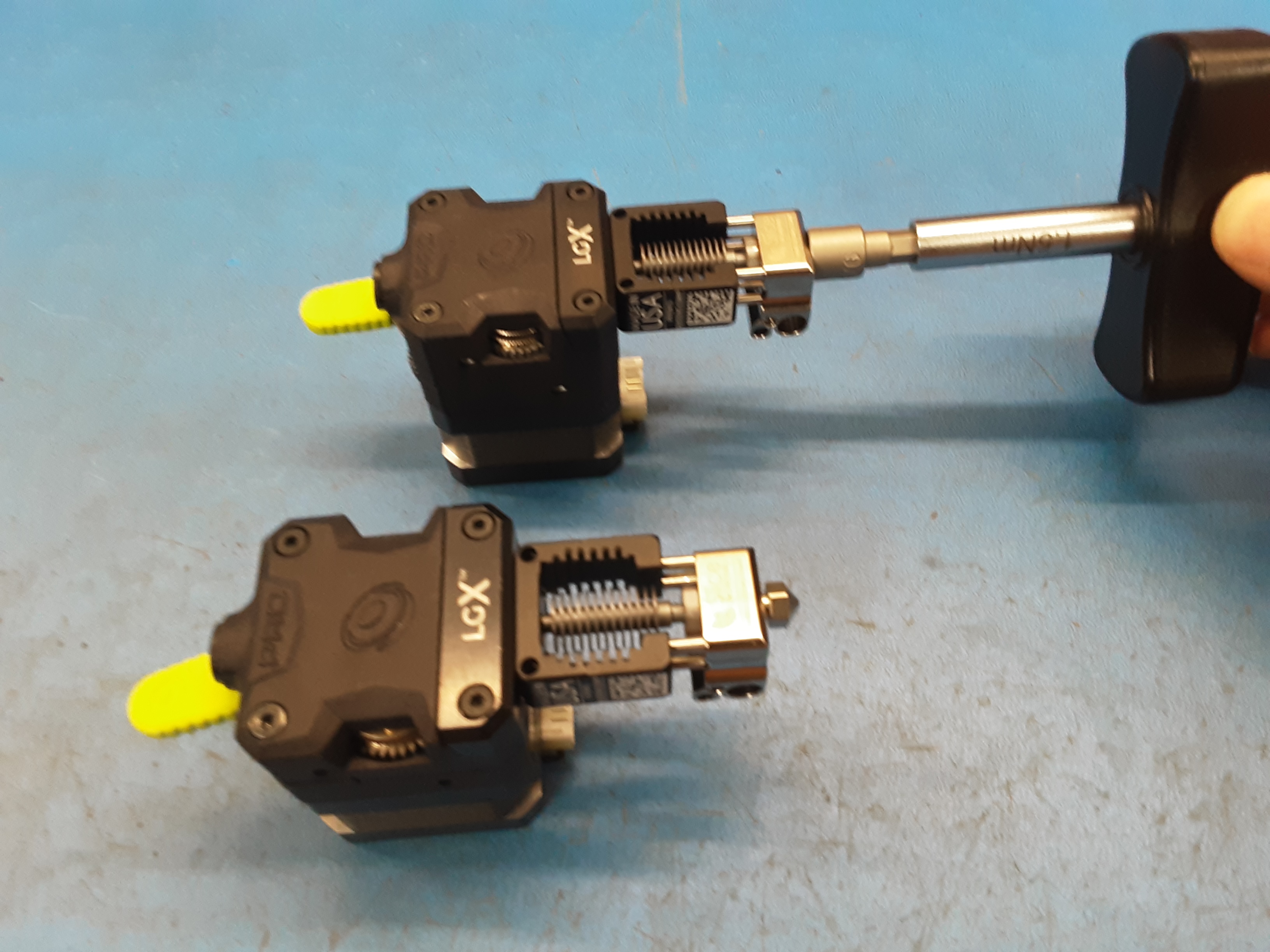
4A) Grab 2x PP-MP0336 (2x PP-MP0335 for TN175) and remove the LGX blocks from the motor.
4B) Save the blocks and the screws to be used later.
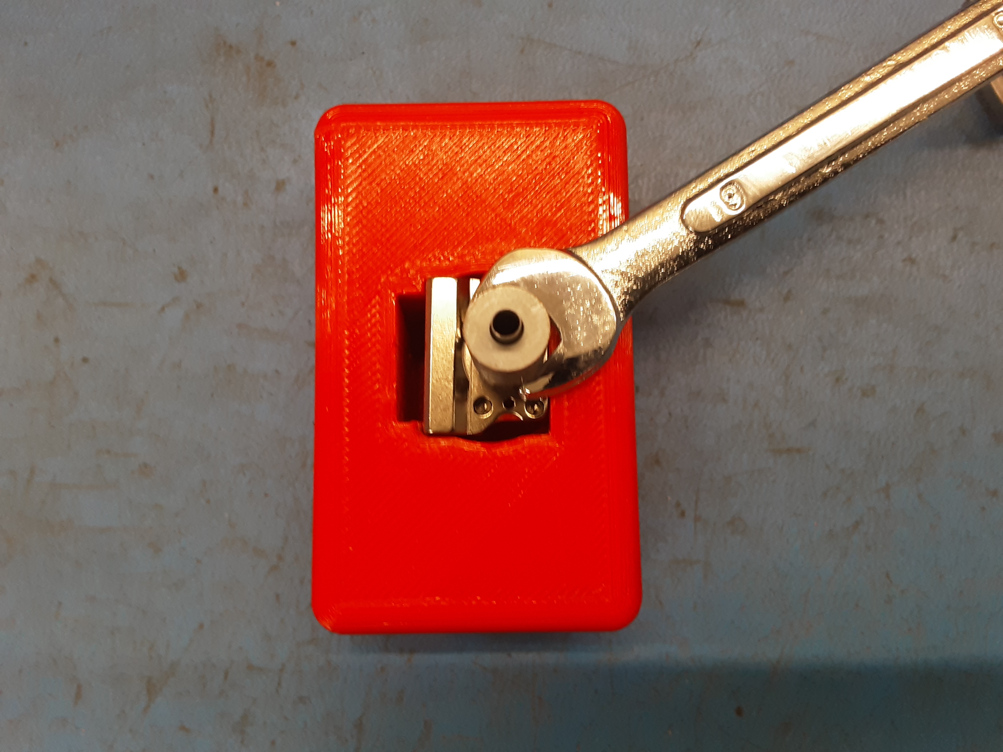
4C) Screw 2x PP-MP0352 into 2x PP-MP0338. (2x PP-MP0505 into 2x PP-MP0357 for TN175)
4D) Using the red block jig and a 9mm wrench tighten the heat breaks into the hot blocks. Be careful to not over tighten these and round off the part.
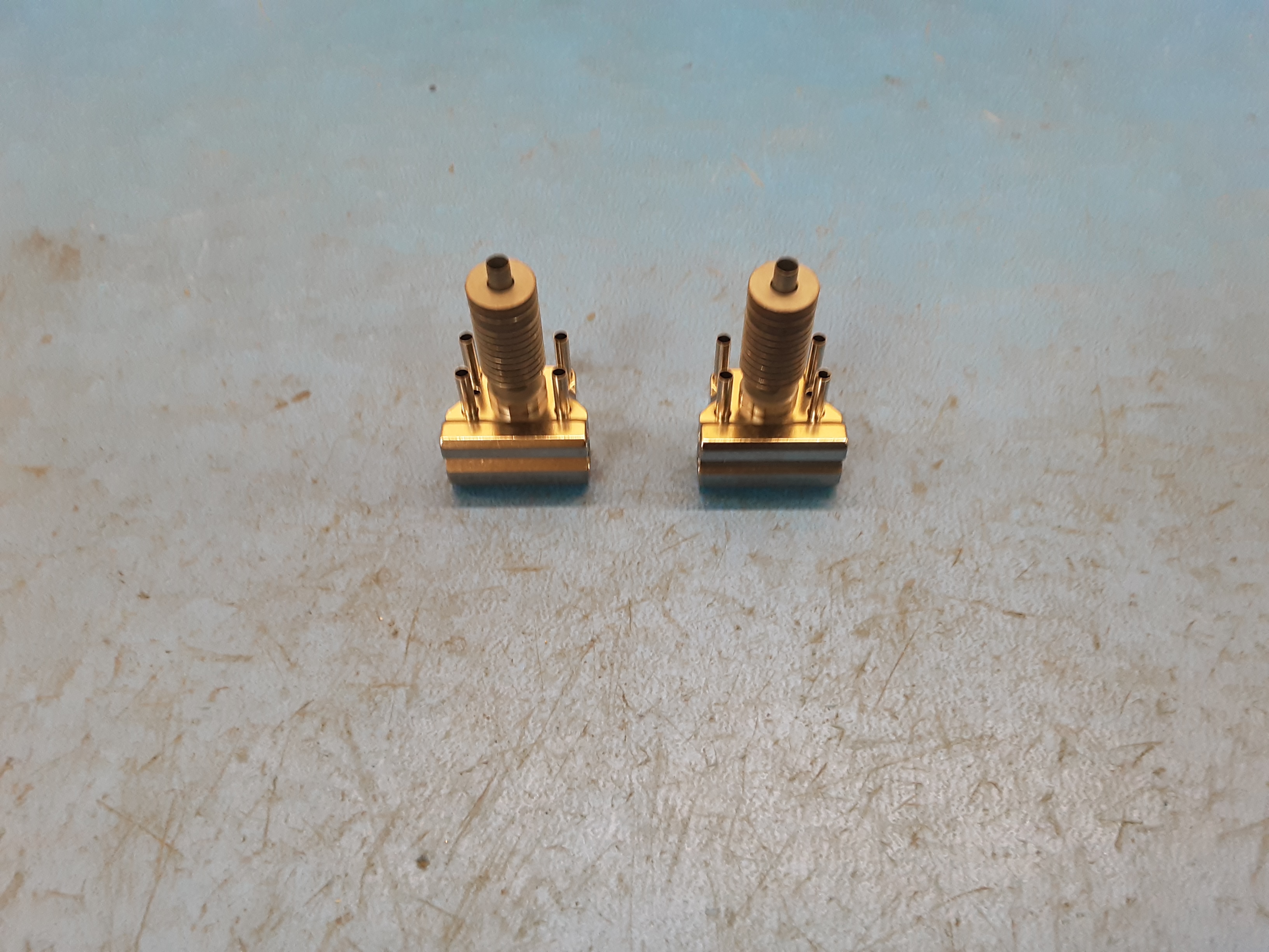
4E) Grab 8 of the posts from HD-MS0100 and insert them into the hot blocks.
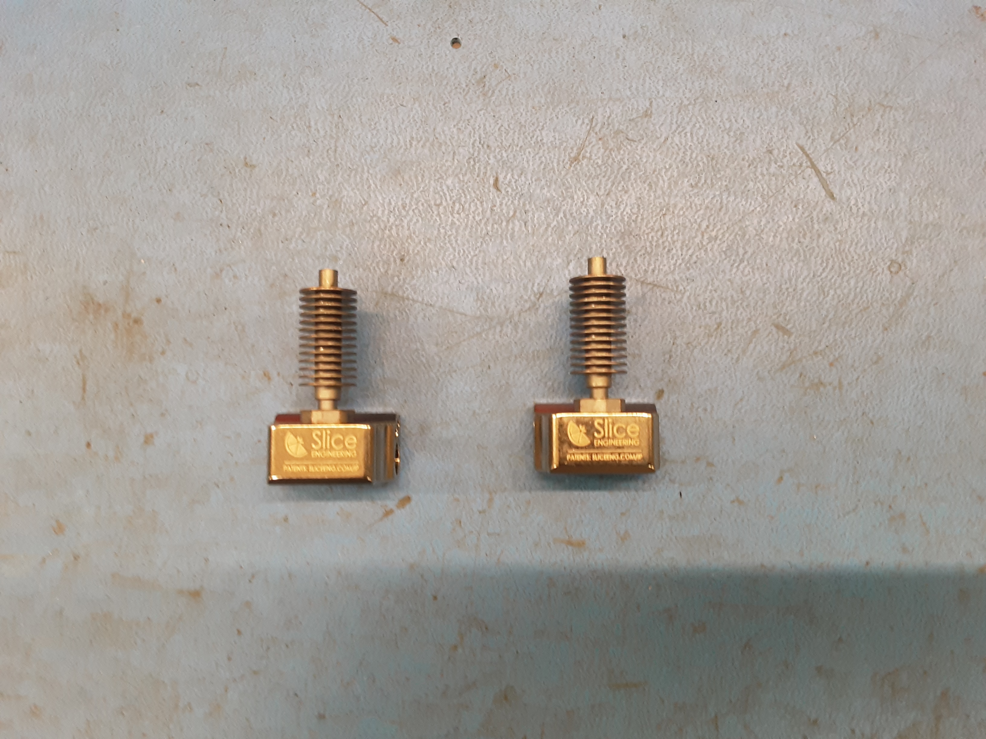
4F) Install 2x PP-MP0345 onto the posts over the heat breaks.
4G) Grab 4 #2 screws from HD-MS0100.
4H) Using the torque screw driver, torque the screws through the hot blocks into PP-MP0345. Double check to make sure the screws were tightened all the way.
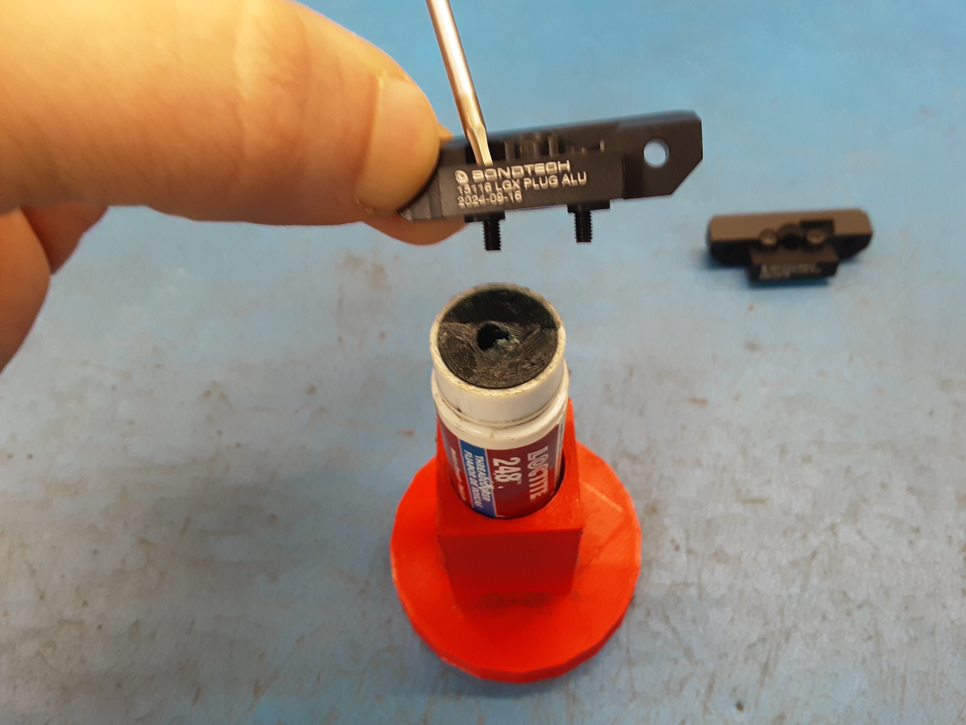
4I) Using 4x HD-BT0284 and loctite install the LGX blocks to PP-MP0345.
4J) For TN175 only insert 2x HD-MS0080 (11mm length) into the LGX block on top of the heat breaks.
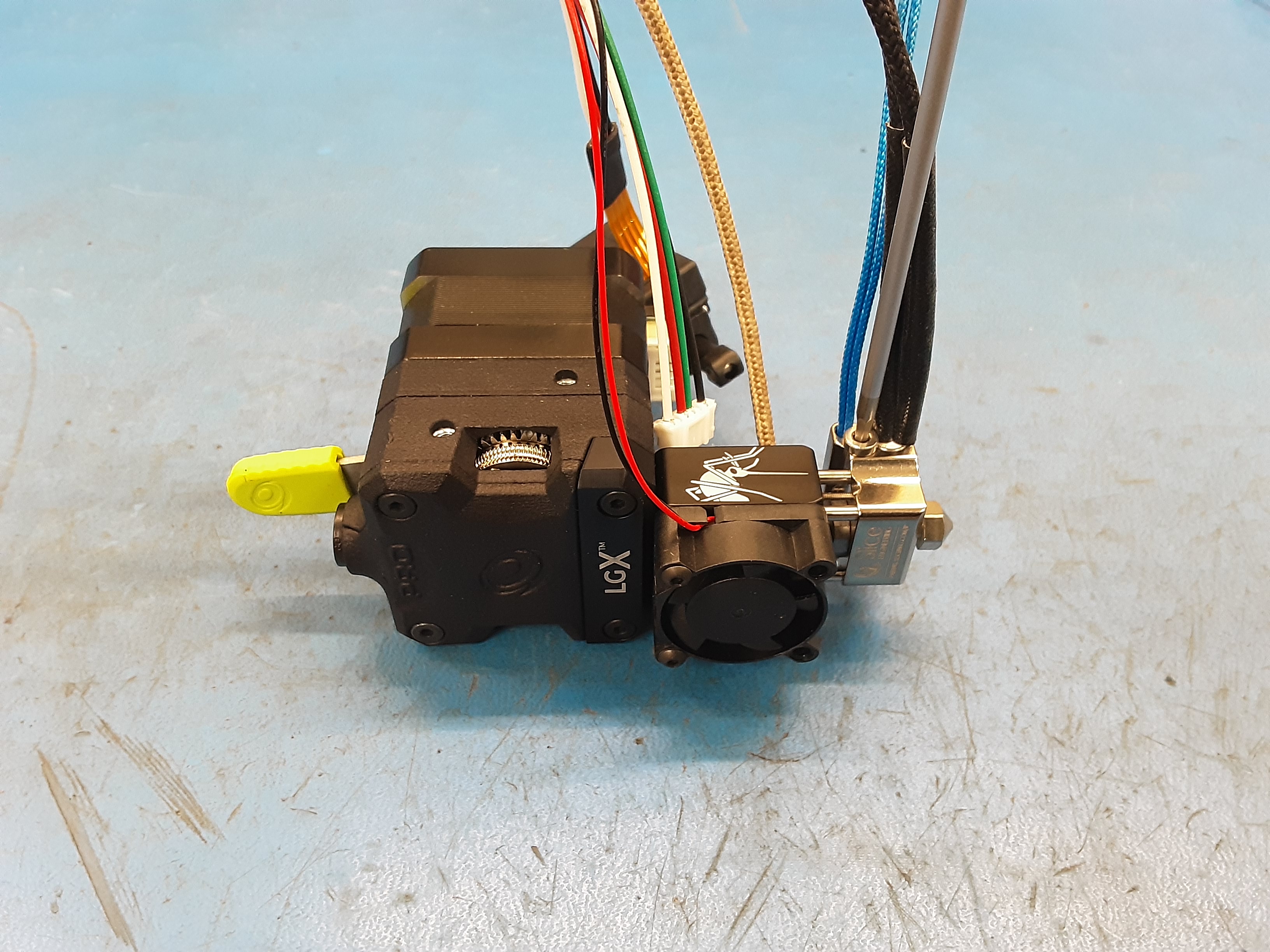
4K) Using the previously removed screws, reattach the LGX blocks to extruder bodies. Make sure the blocks get seated all the way on.
4L) Attach 2x PP-MP0416 (2x PP-MP0412 for TN175) nozzles to the hot blocks using the nozzle torque tool.
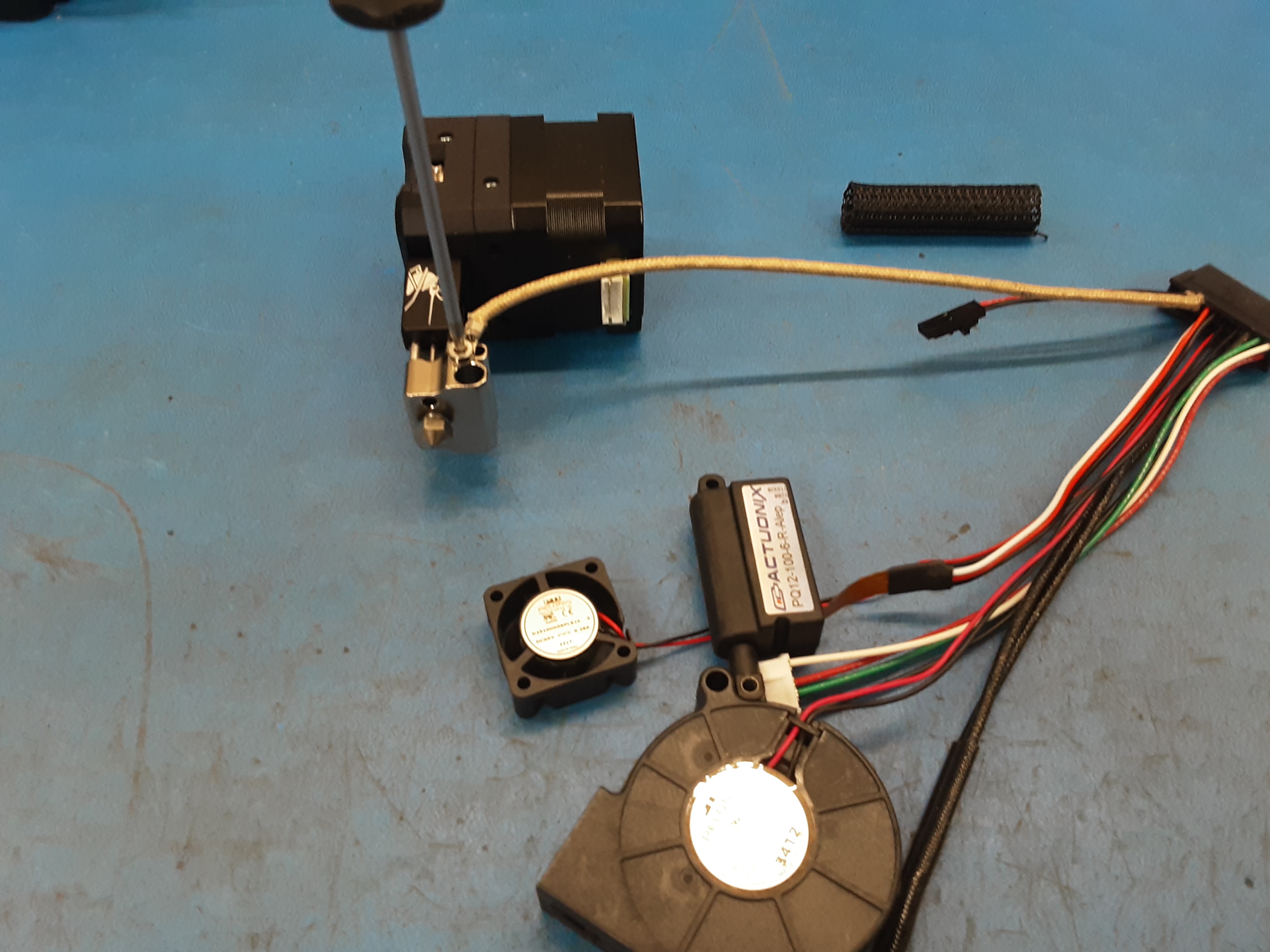
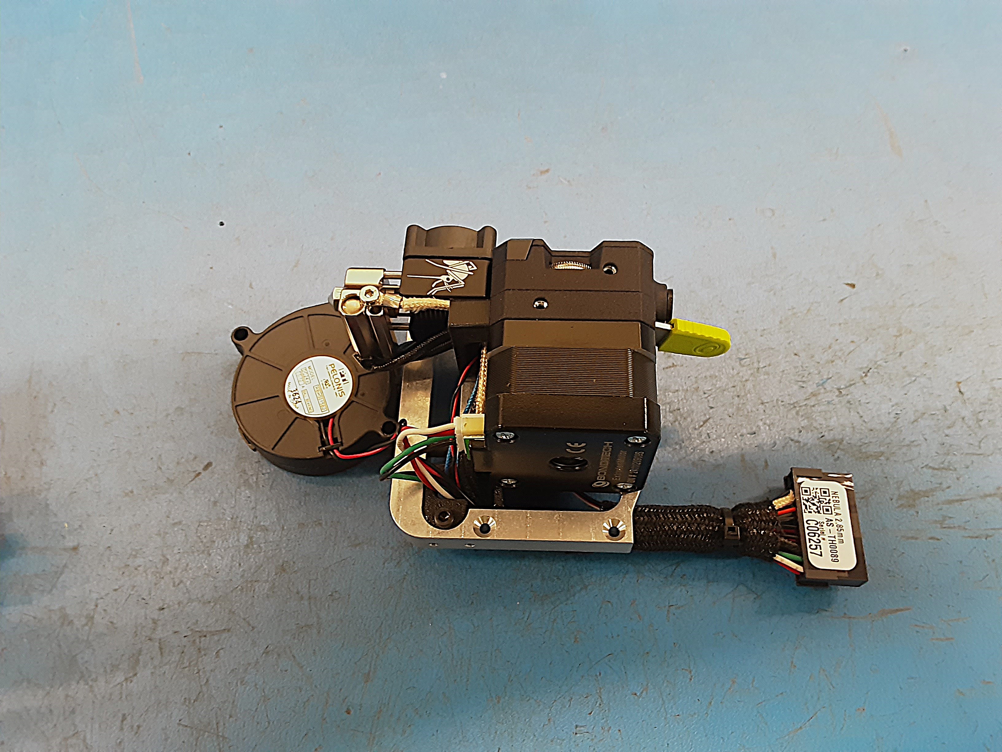
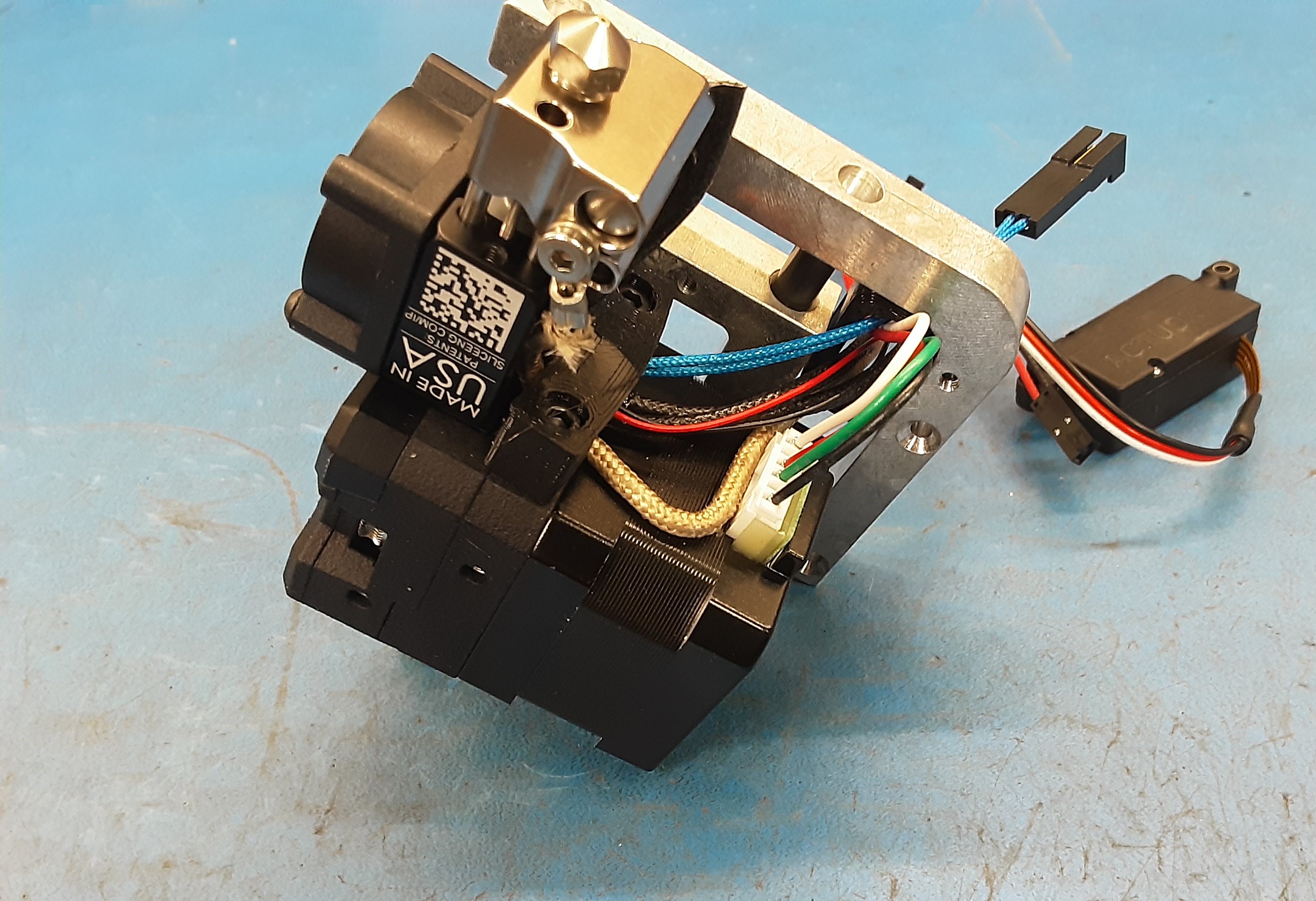
5A) Remove the braiding on AS-CB0210 and attach the ground wire as shown using screw #1 from
HD-MS0100.
5B) Attach the small fan from AS-CB0210 in the orientation shown using 2x HD-BT0261.
5C) Install the heater cartridge from AS-CB0210 and EL-TH0015 and secure them using screw #1 from
HD-MS0100.
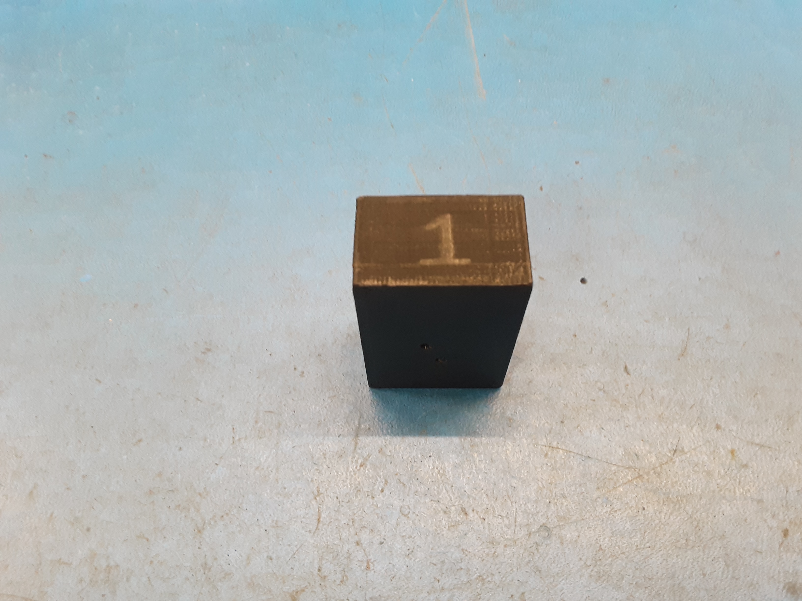
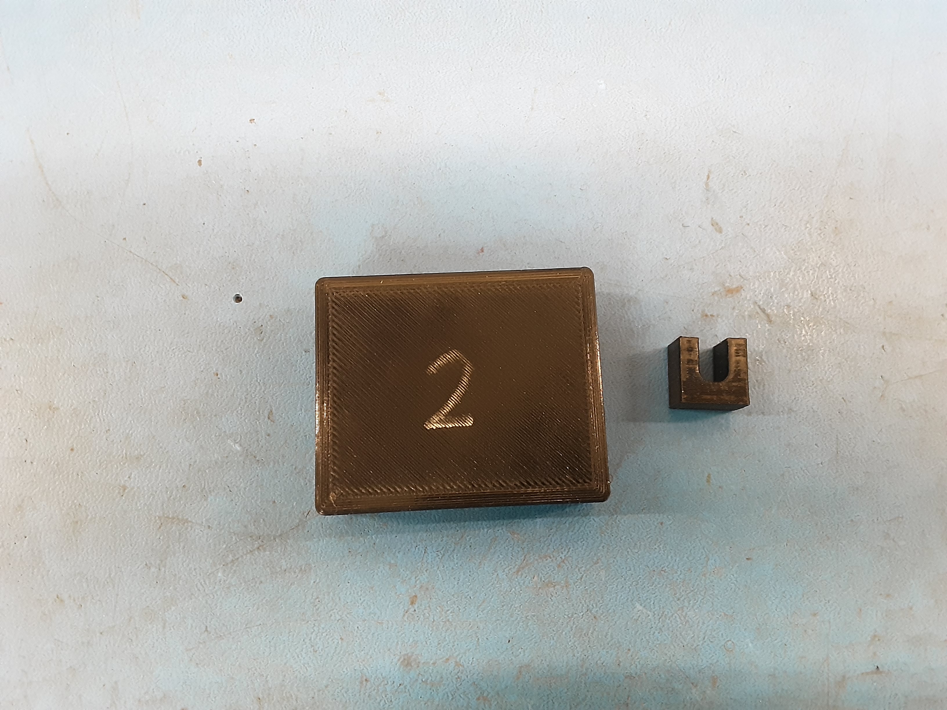
5D) Grab the black block #1.
5E) Use the black block #1 to help balance the tool head for the next few steps.
5F) Bend the ground wire, heater cartridge, small fan wire, and EL-TH0015 down to follow PP-MP0345 to the motor. Have a 90 degree bend having the wires towards the motor plug.
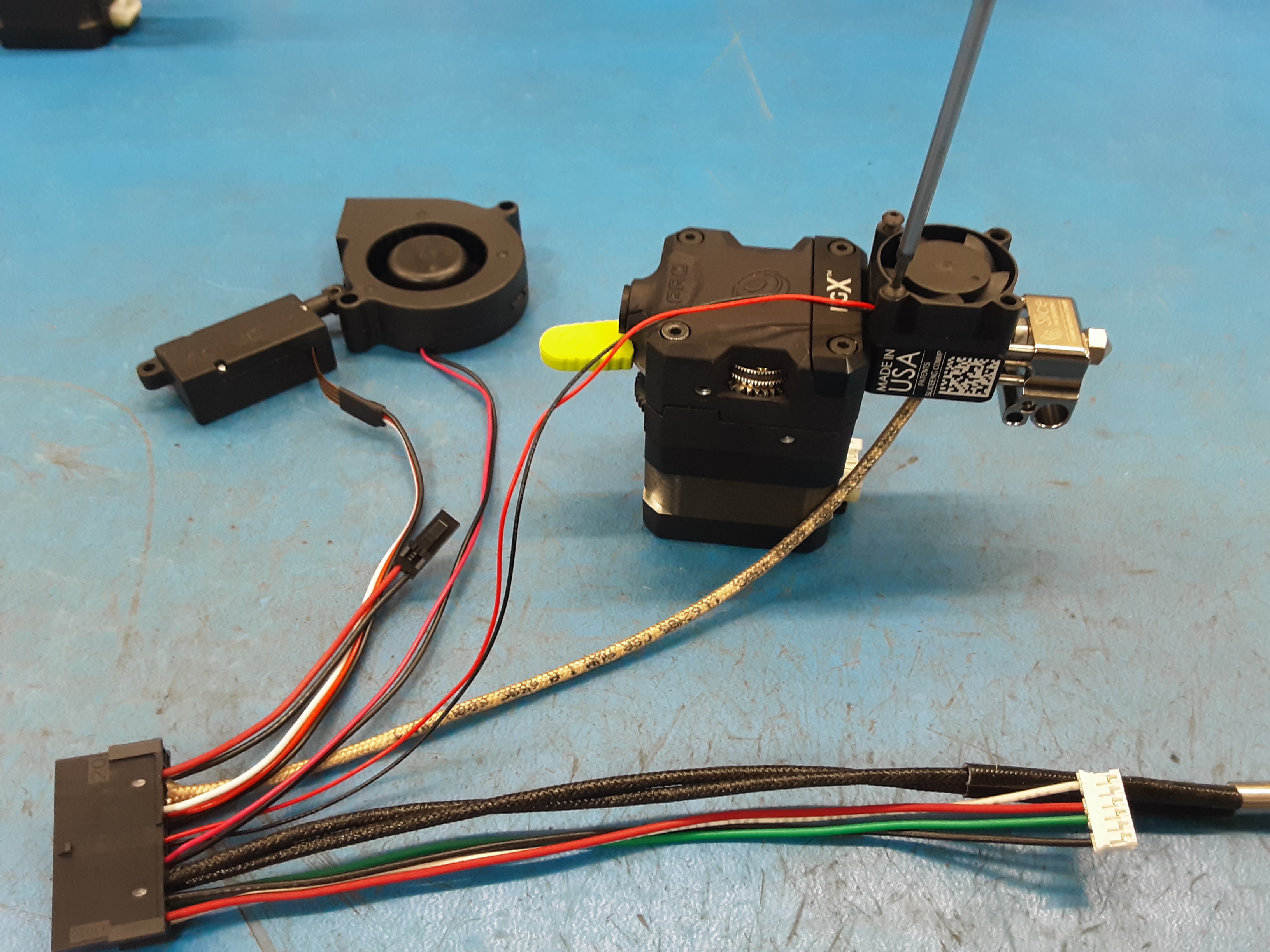
5G) Attach PP-GP0746 using 2x HD-BT0007. Double check to make sure no wires are being pinched while tightening this part down.
5H) Grab PP-FP0244, 2x HD-BT0137, and 2x HD-WA0027.
5I) Loosely attach PP-FP0244 to the motor using 2x HD-BT0137 and 2x HD-WA0027.
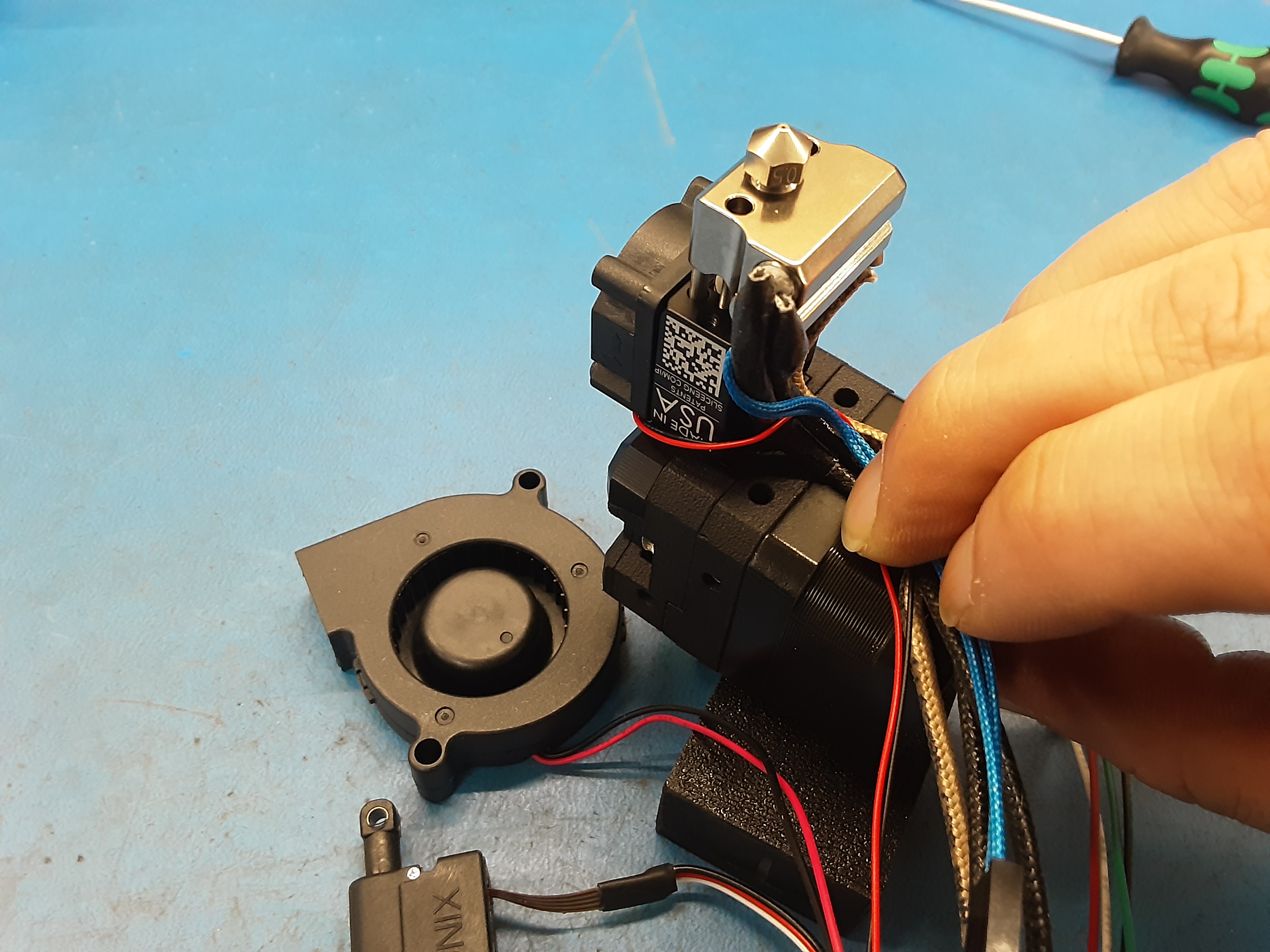
5J) Using PP-FP0245 hook all the wires except for the actuator wires.
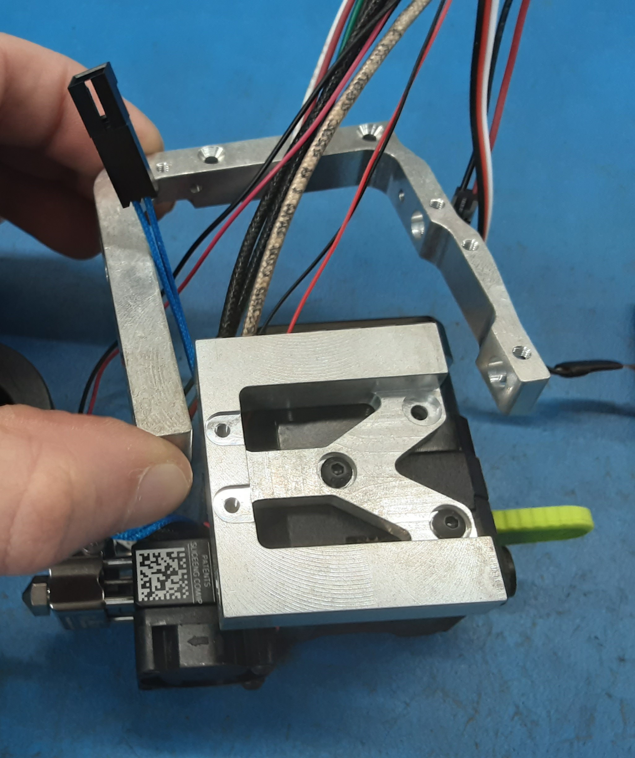
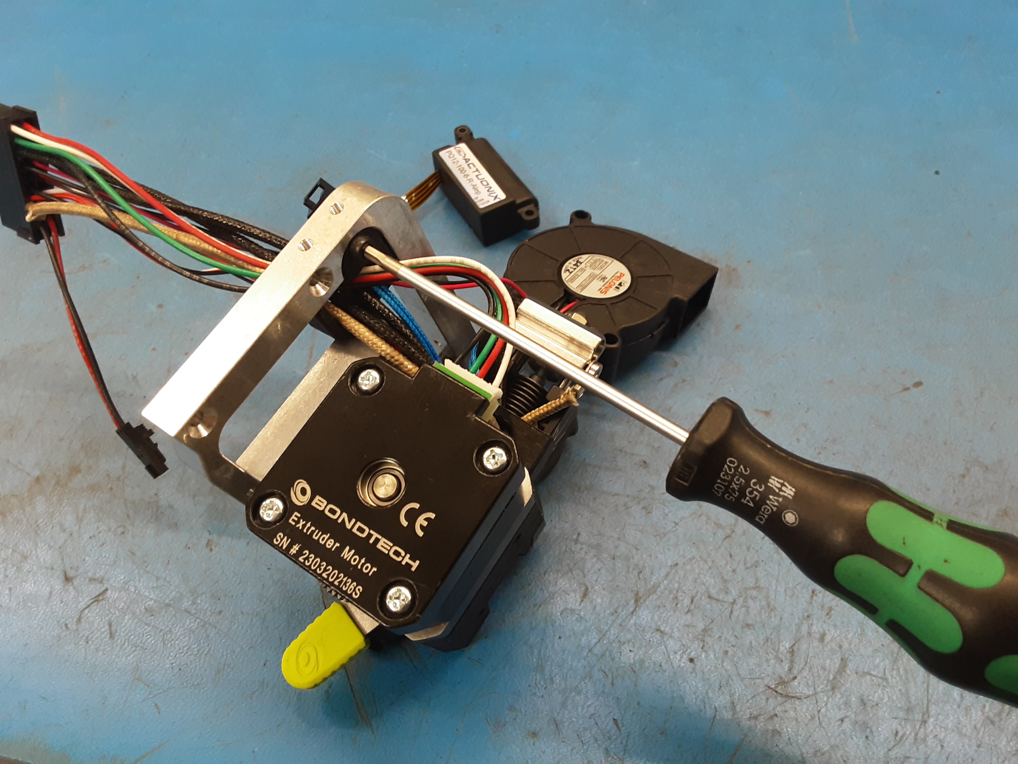
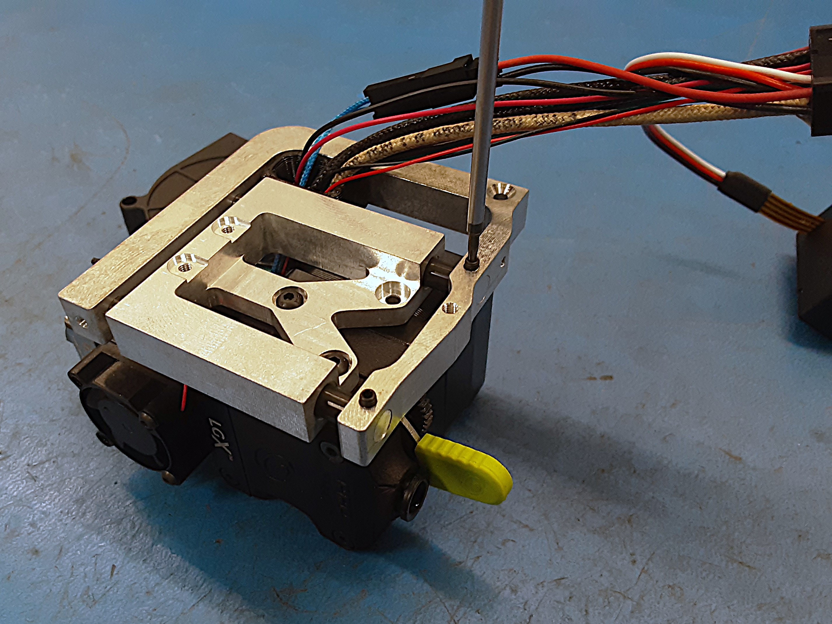
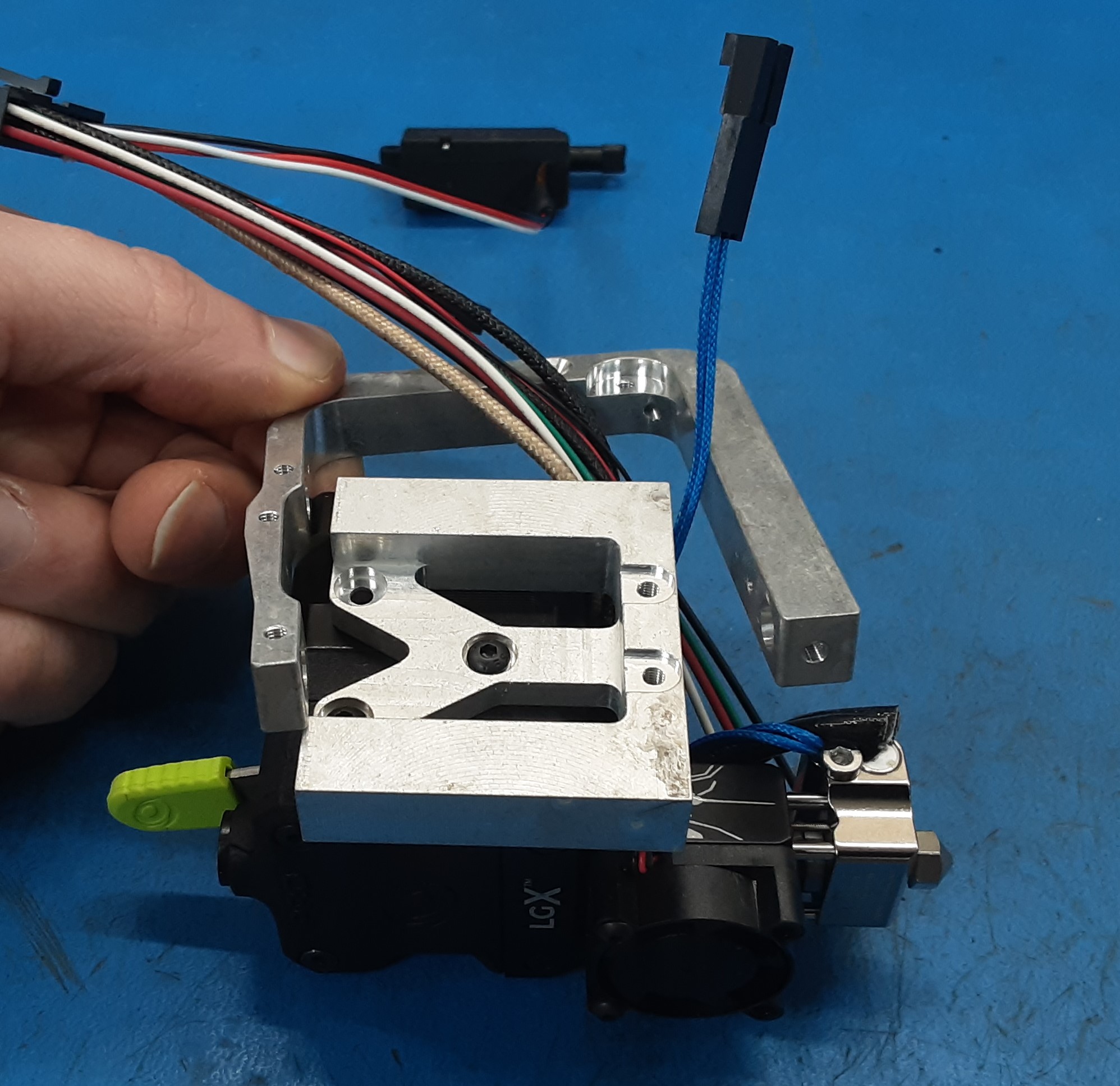
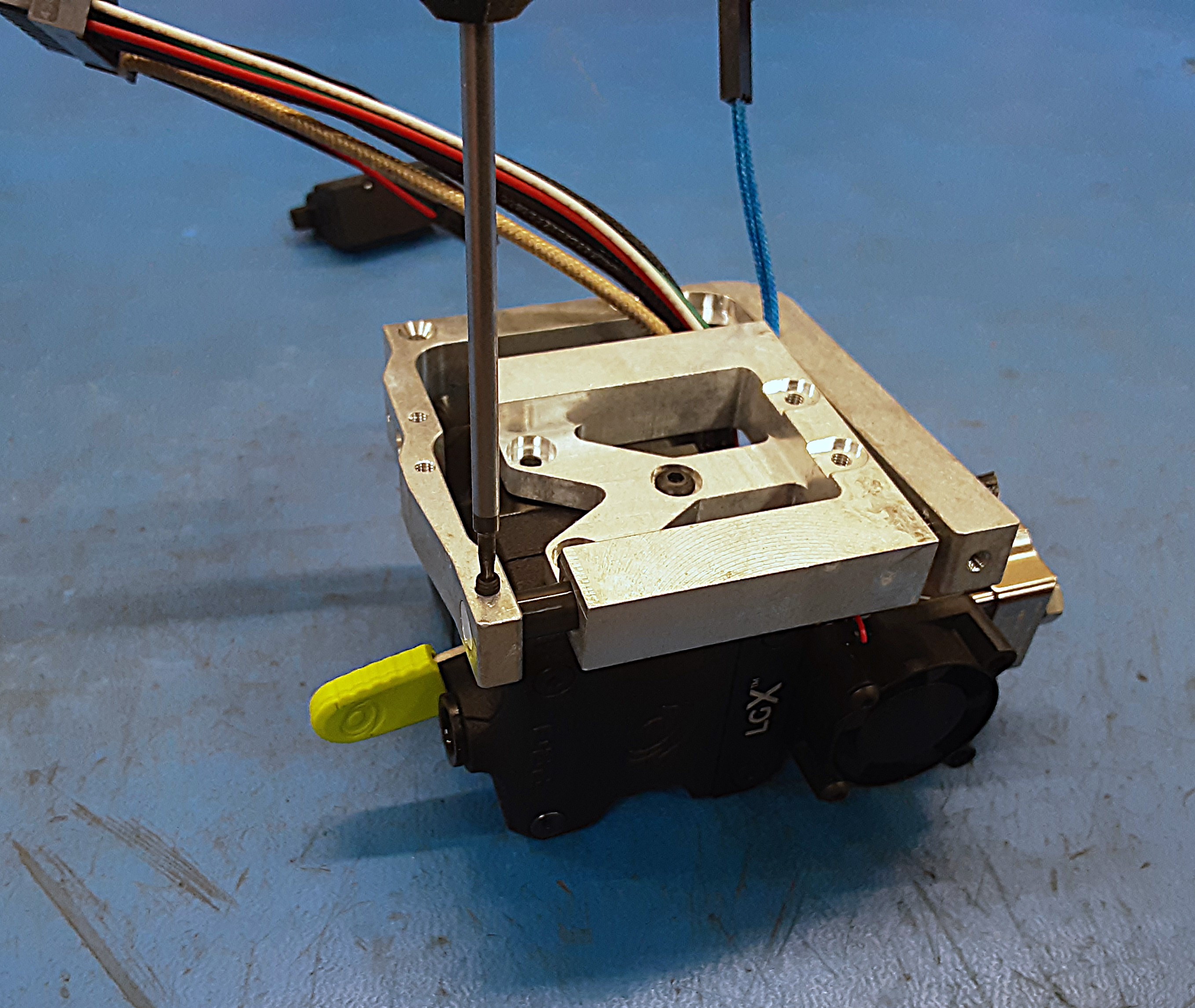
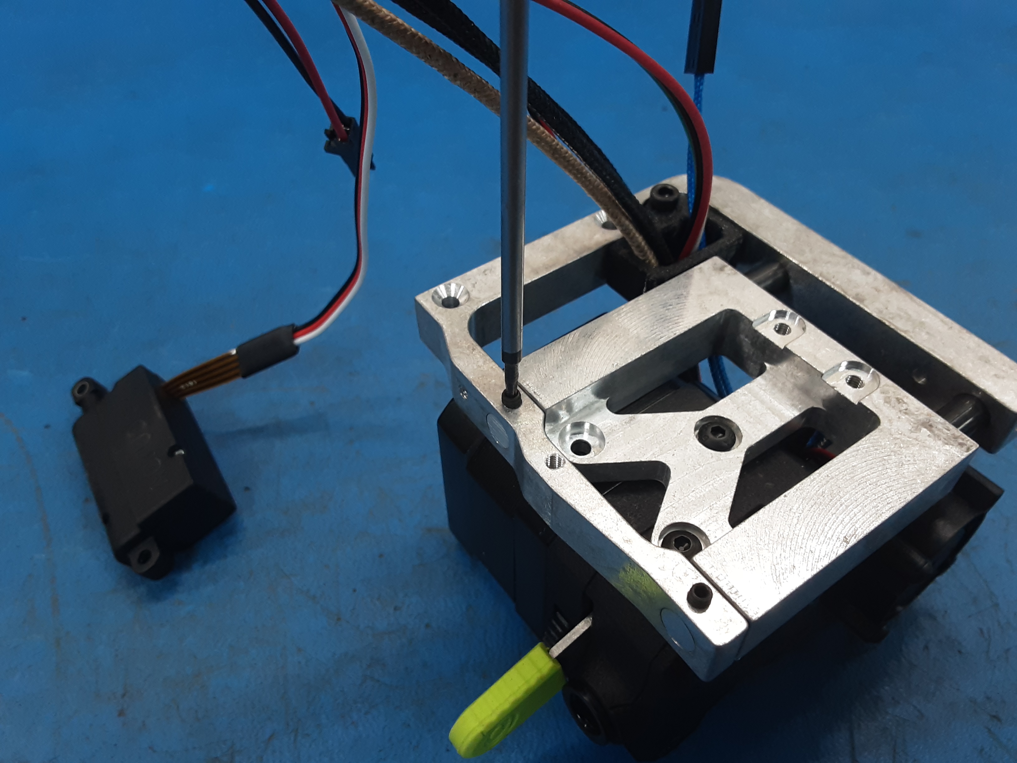
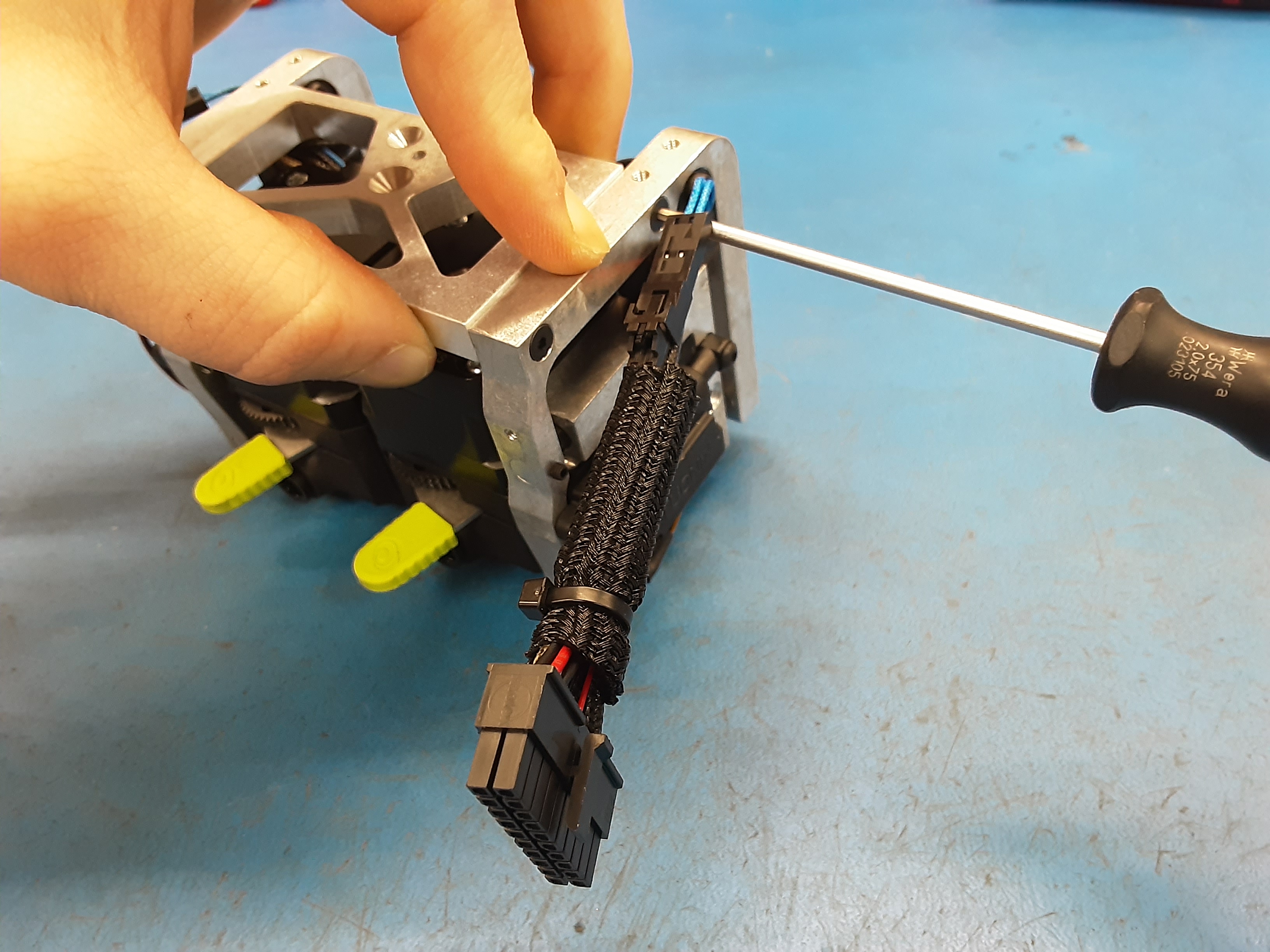
5K) Install 1x HD-RD0070 in the spot furthest from the wires. Use HD-BT0162 to secure the rod. Be careful not to force the rod in. The rod should sit flush with PP-FP0245 on the side with the set screw.
5L) Can fold PP-FP0245 down a bit. Put all the wires except for the actuator wires in PP-GP0743.
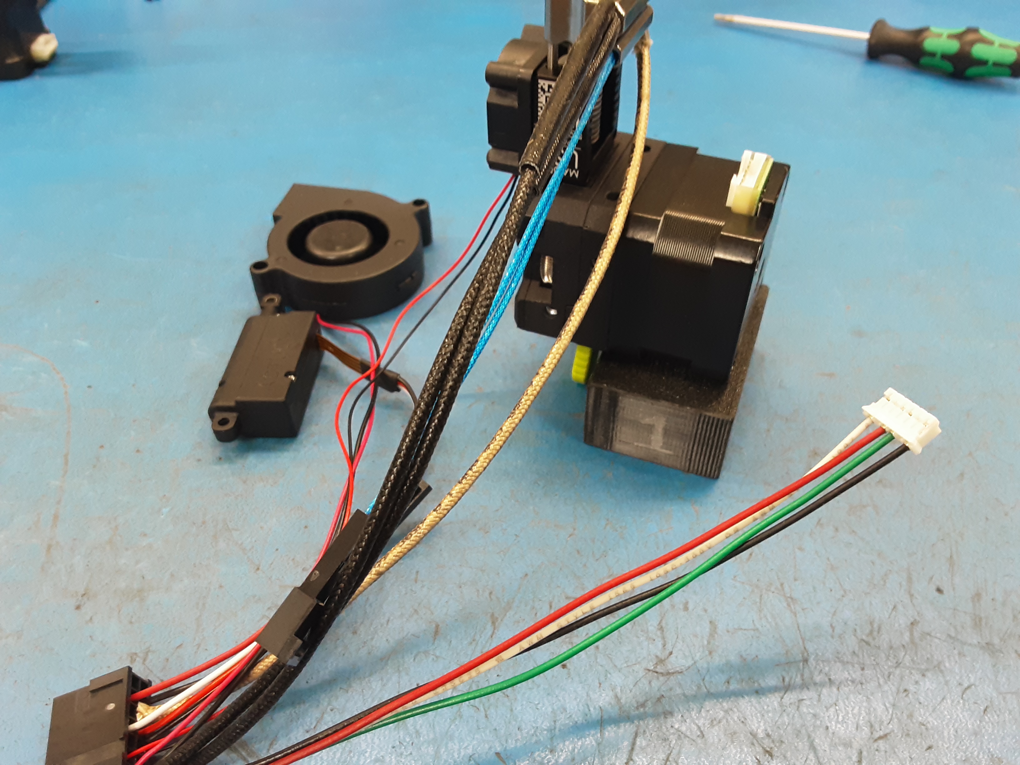
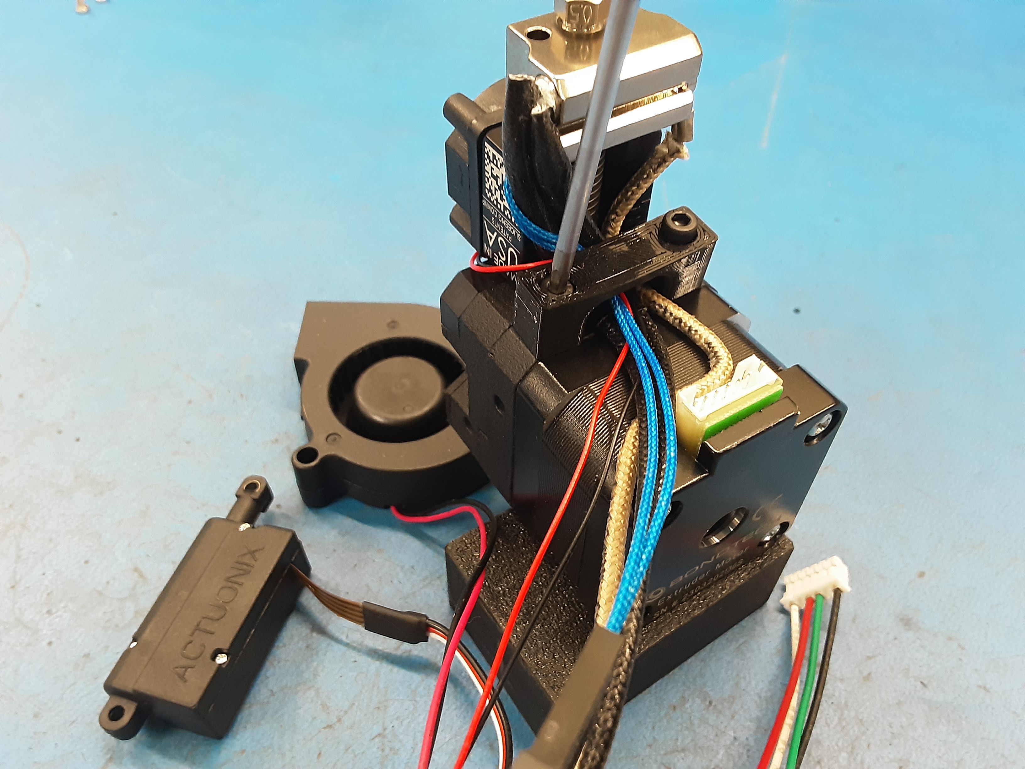
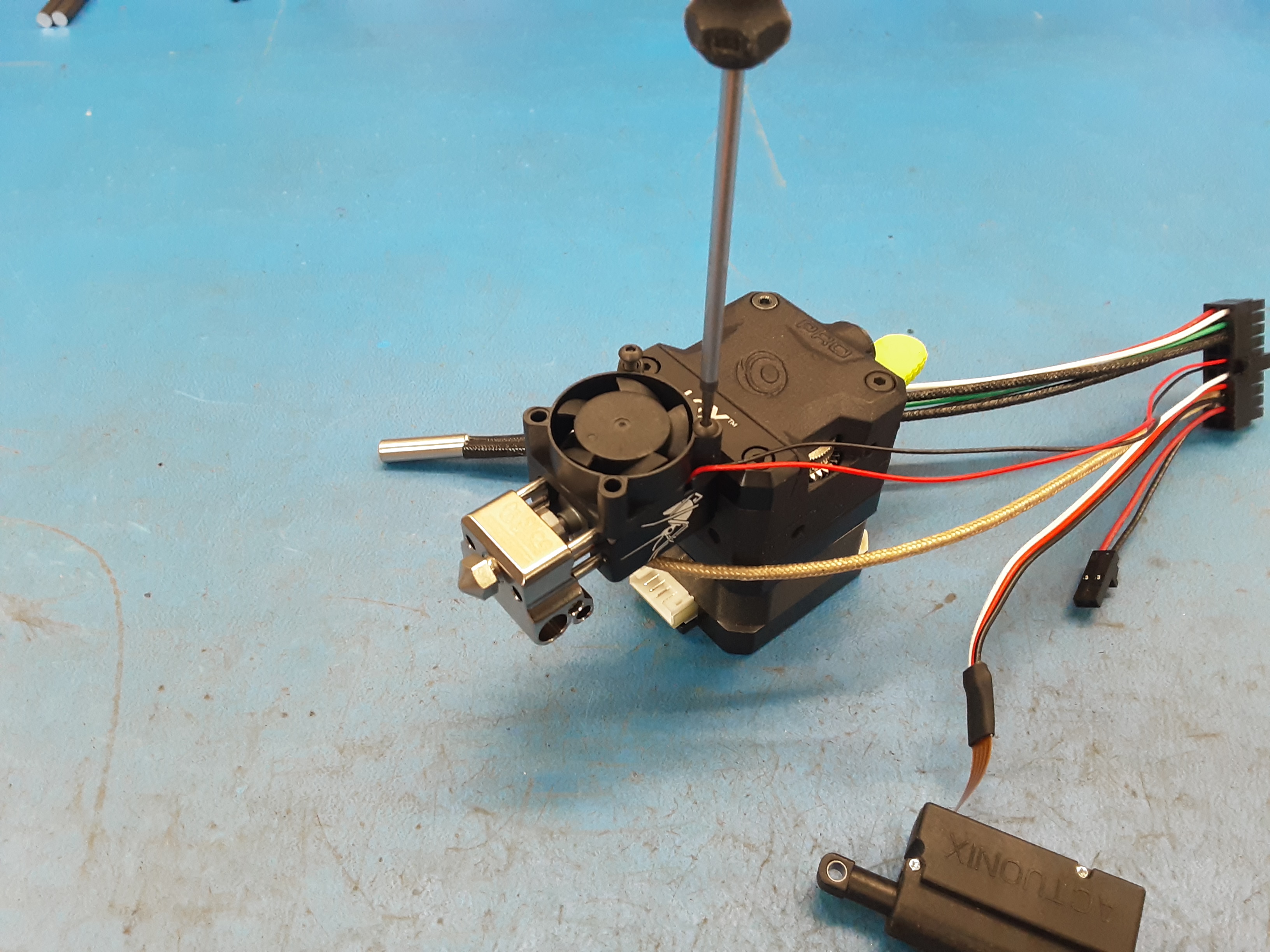
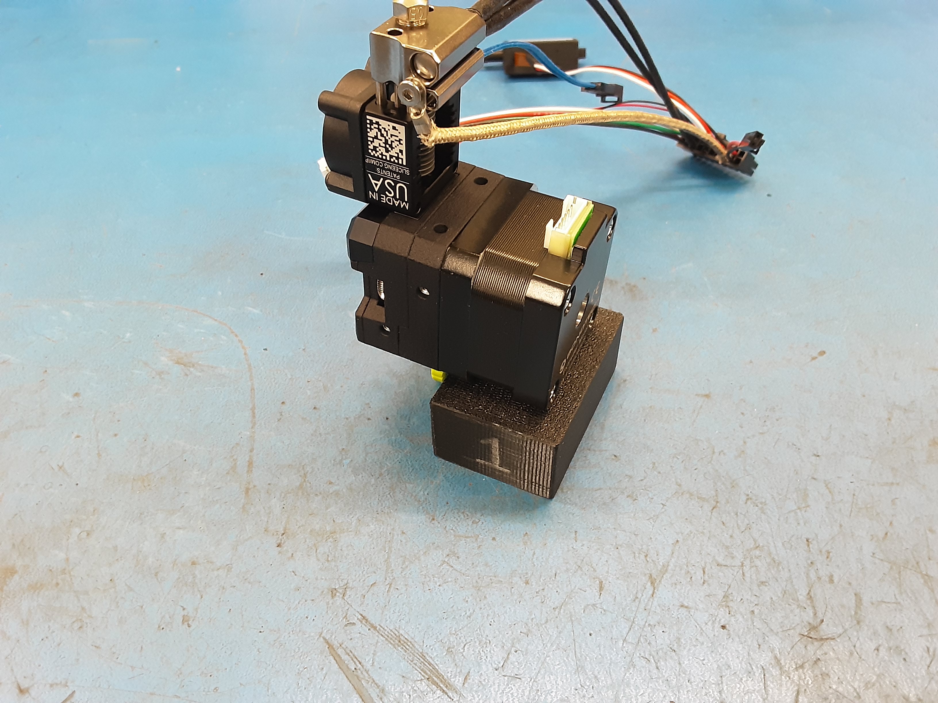
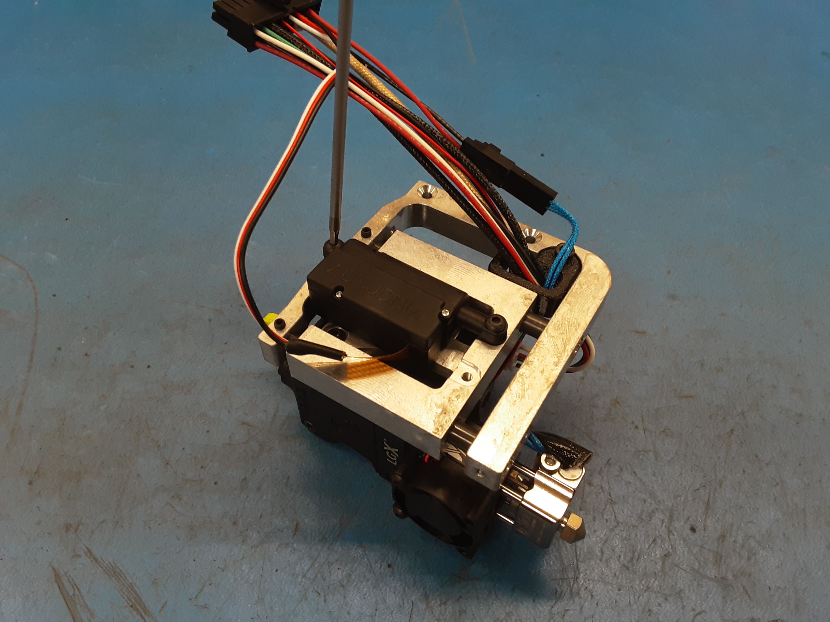
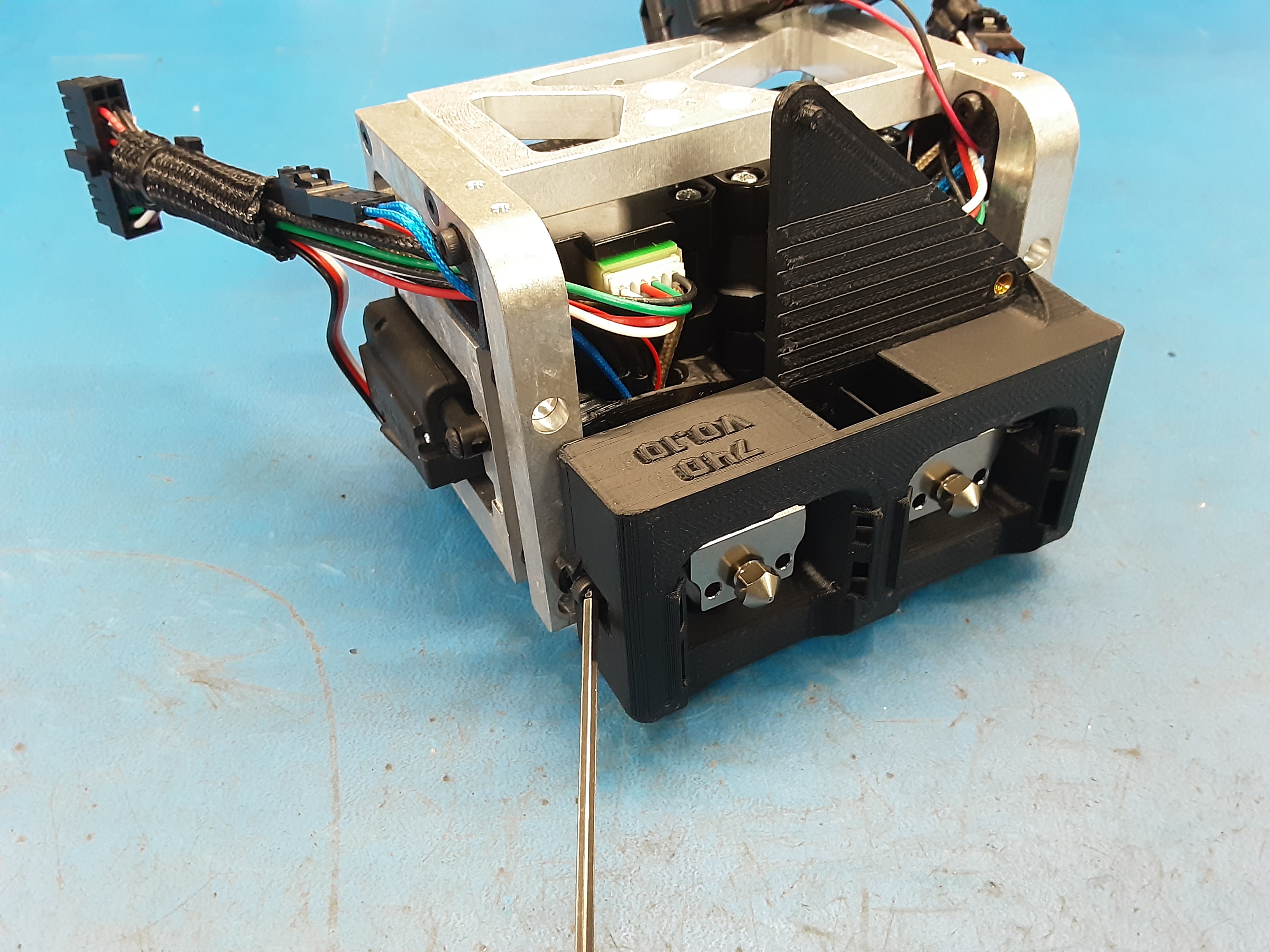
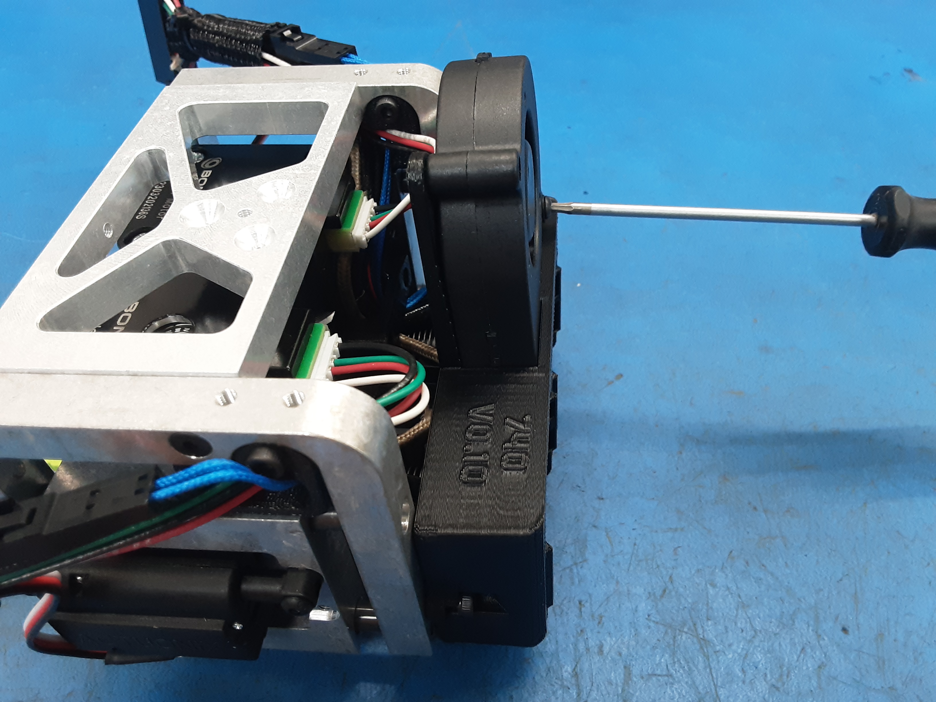
5M) Fold PP-FP0245 back up and attach PP-GP0743 using HD-BT0157. Double check to make sure the wires stayed in PP-GP0743. Plug in the motor wire from AS-CB0210 into the motor.
5N) Install HD-RD0070 in the spot closest to the wires. Use HD-BT0162 to secure the rod. Be careful not to force the rod in. The rod should sit flush with PP-FP0245 on the side with the set screw. PP-FP0244 should slide back and forth fairly freely.
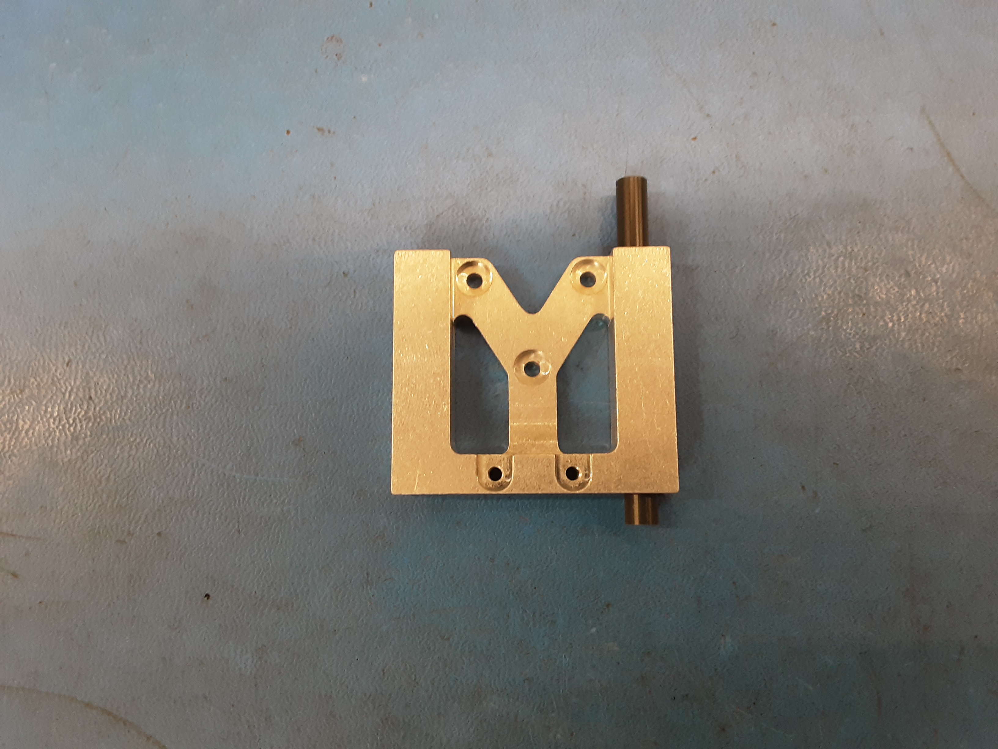
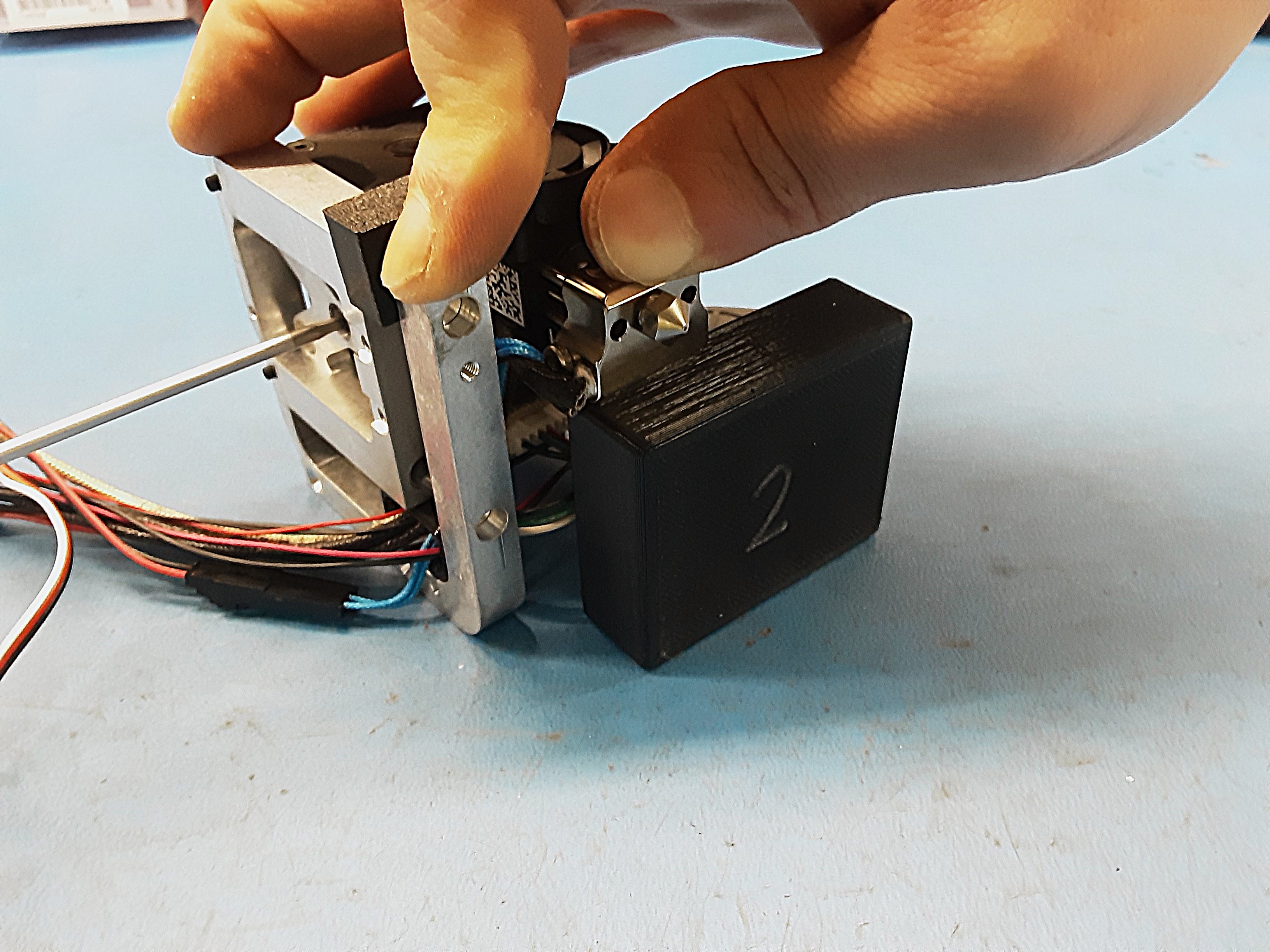
5O) Grab the black block #2 and the “U” spacer.
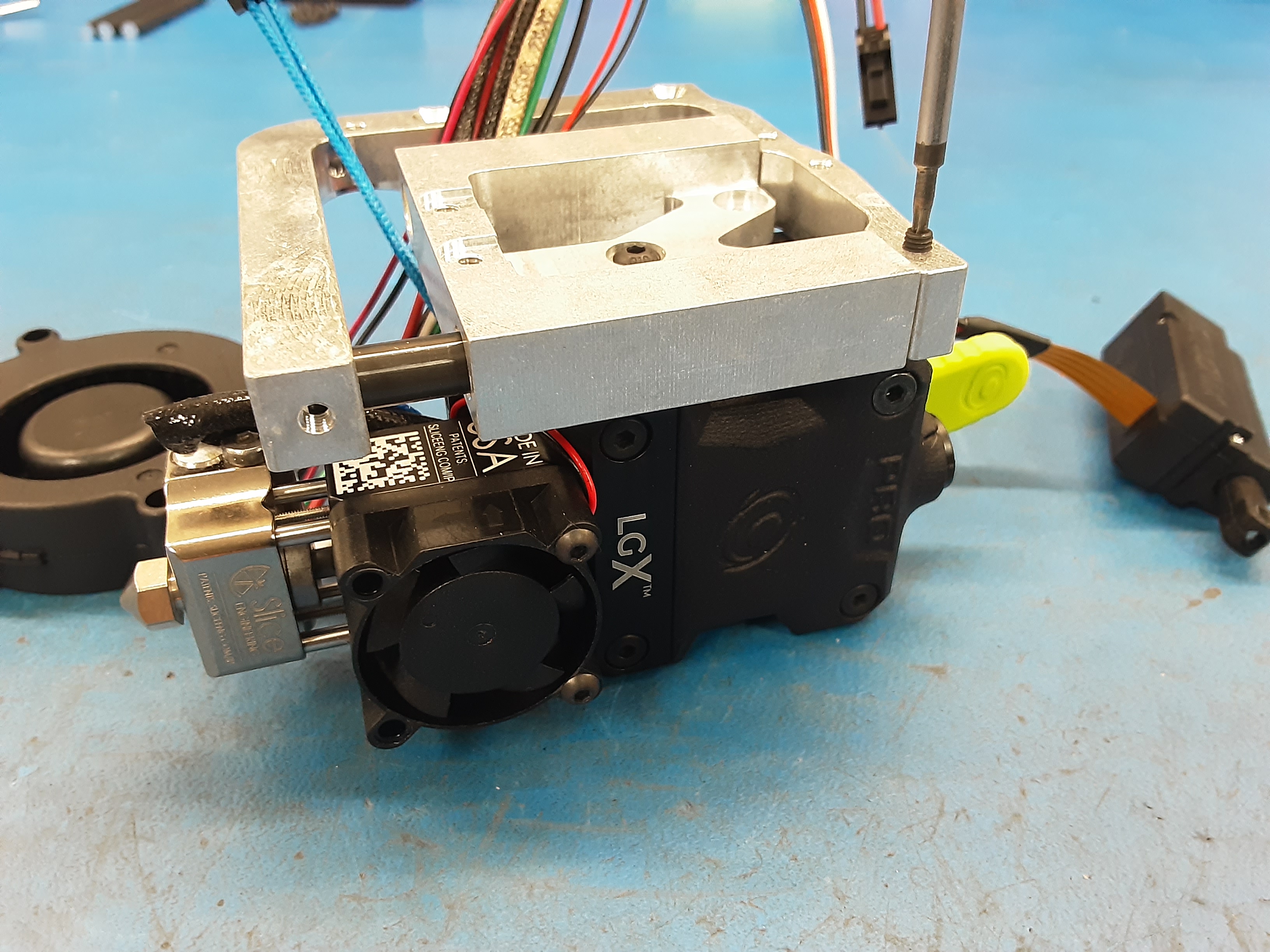
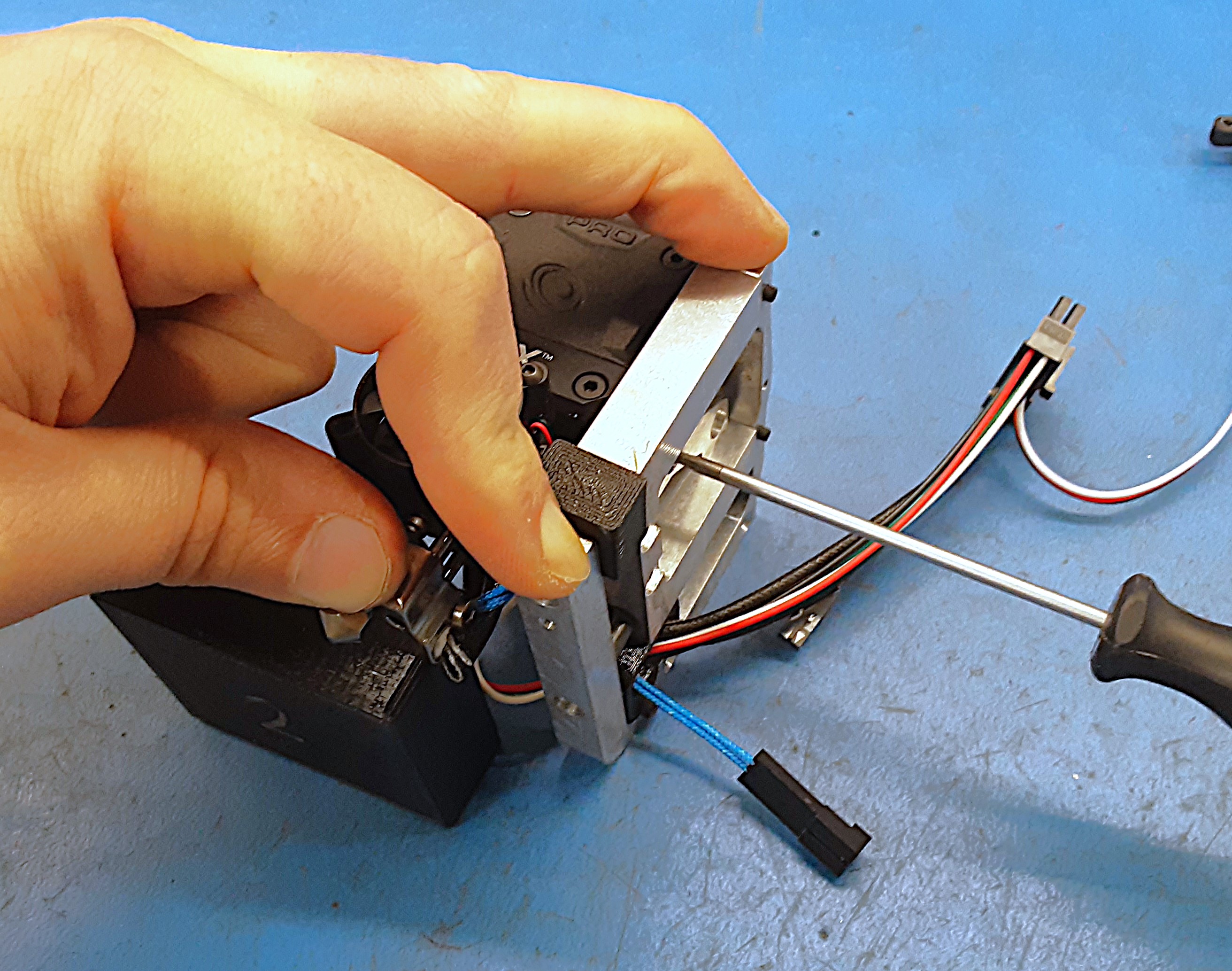
5P) Put the “U” spacer on HD-RD0070 in between PP-FP0244 and PP-FP0245. With the motor assembly in the orientation shown slide the #2 block under the hot block. Make sure there are no wires in between the hot block and the #2 block as well as PP-FP0245 and the table. While pushing down on the hot block and both sides of PP-FP0245 tighten both HD-BT0137 screws in PP-FP0244.
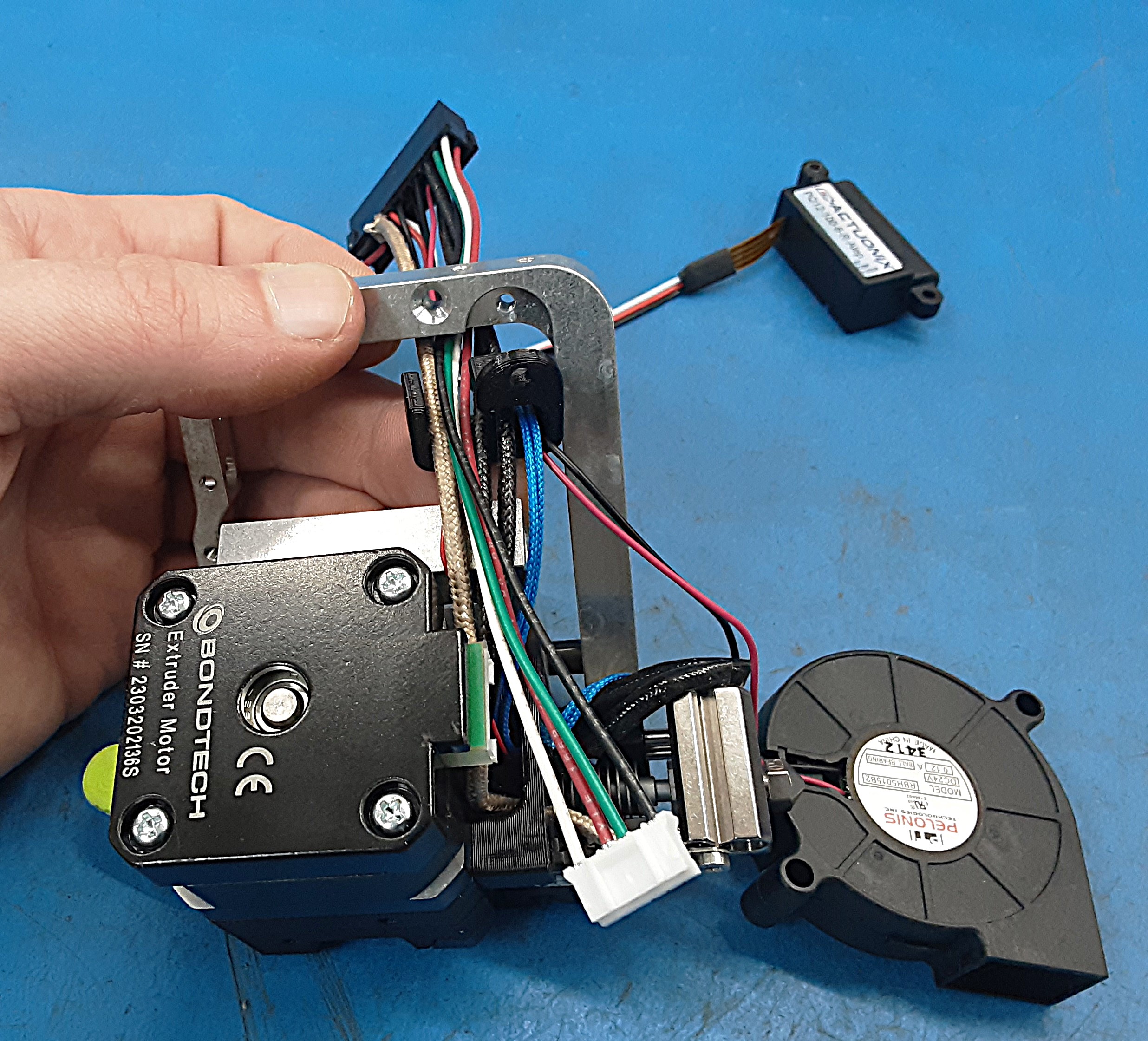
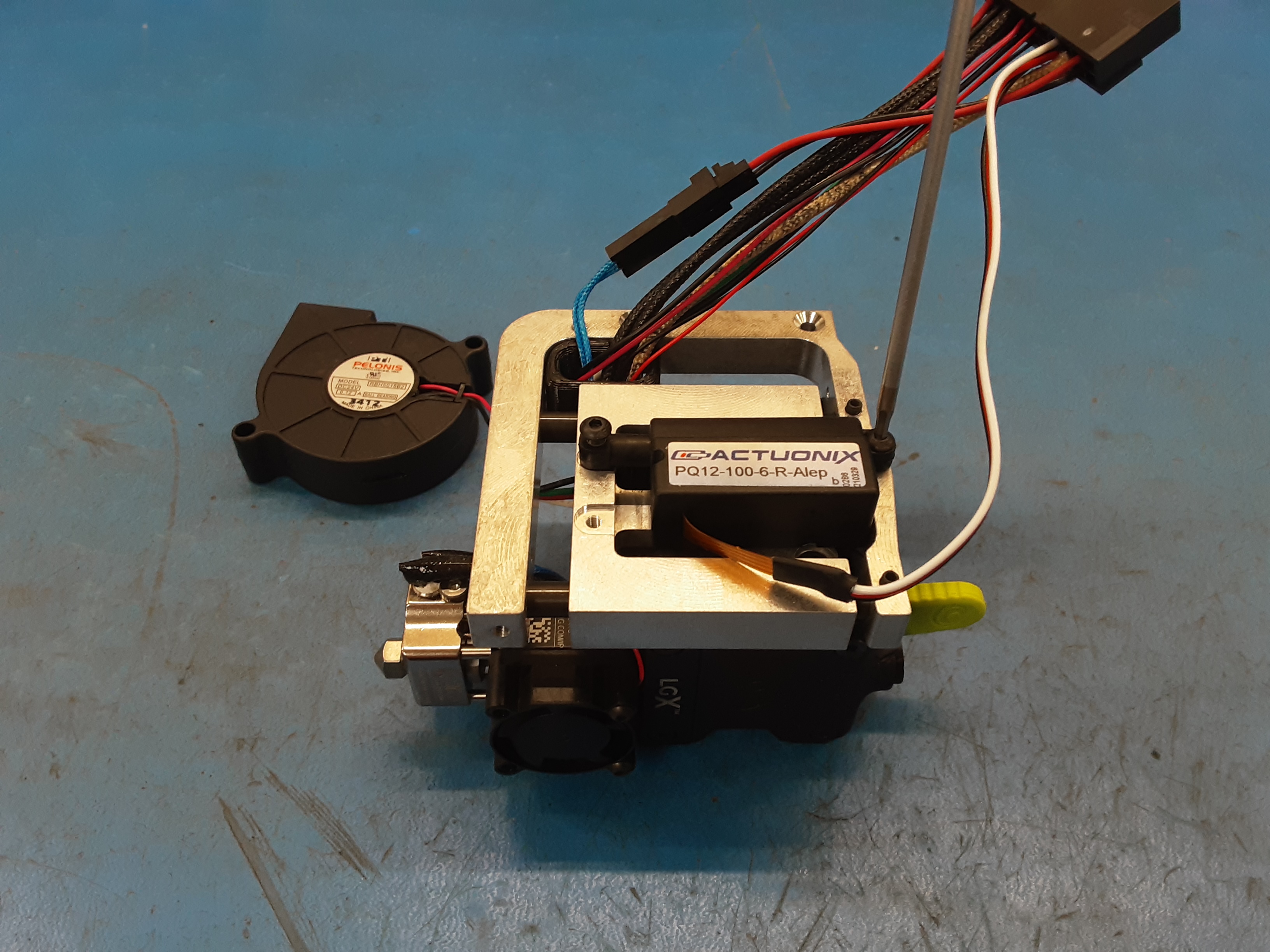
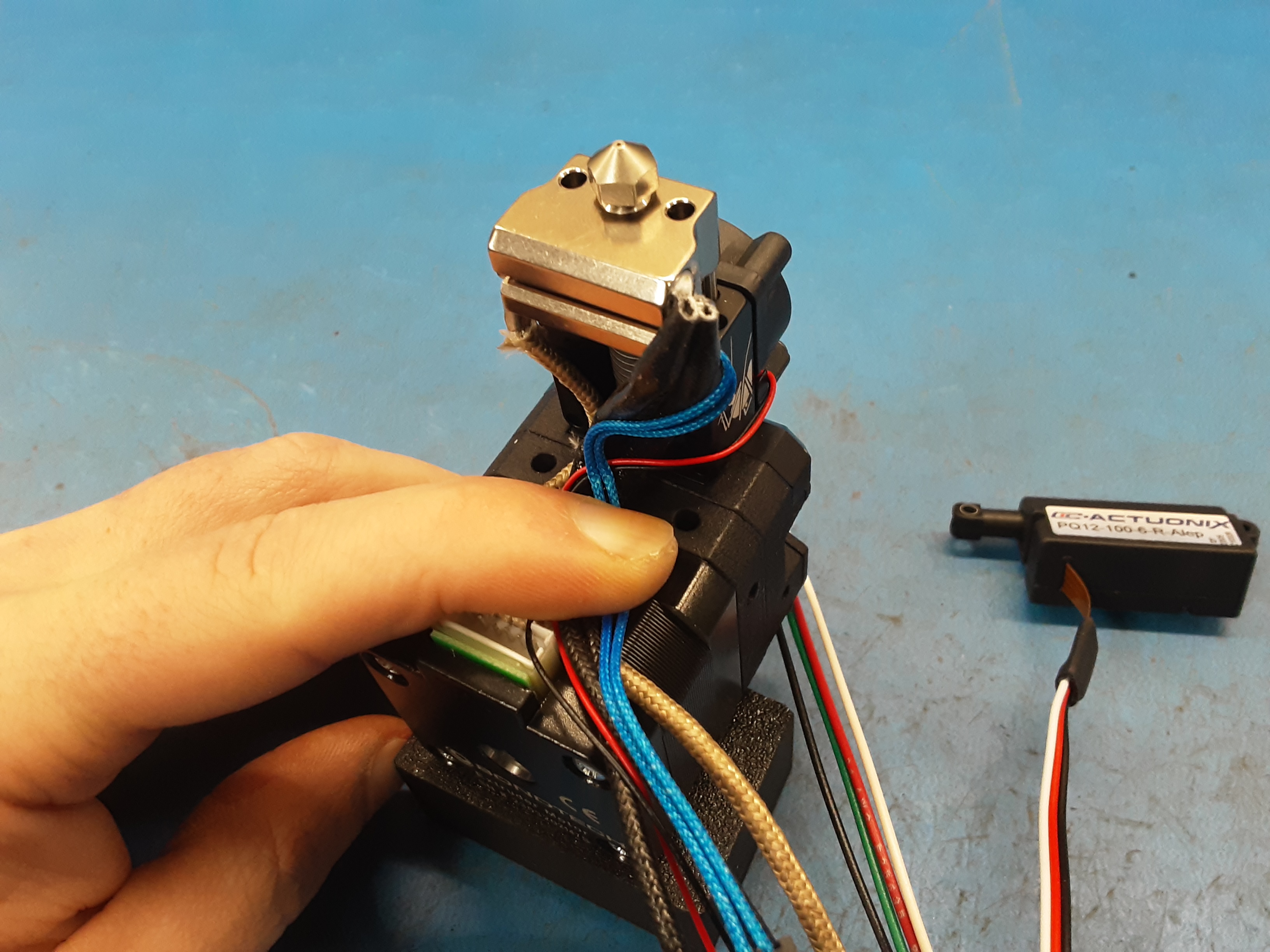
5Q) Attach the actuator to PP-FP0244 and PP-FP0245 using 2x HD-BT0137 screws.
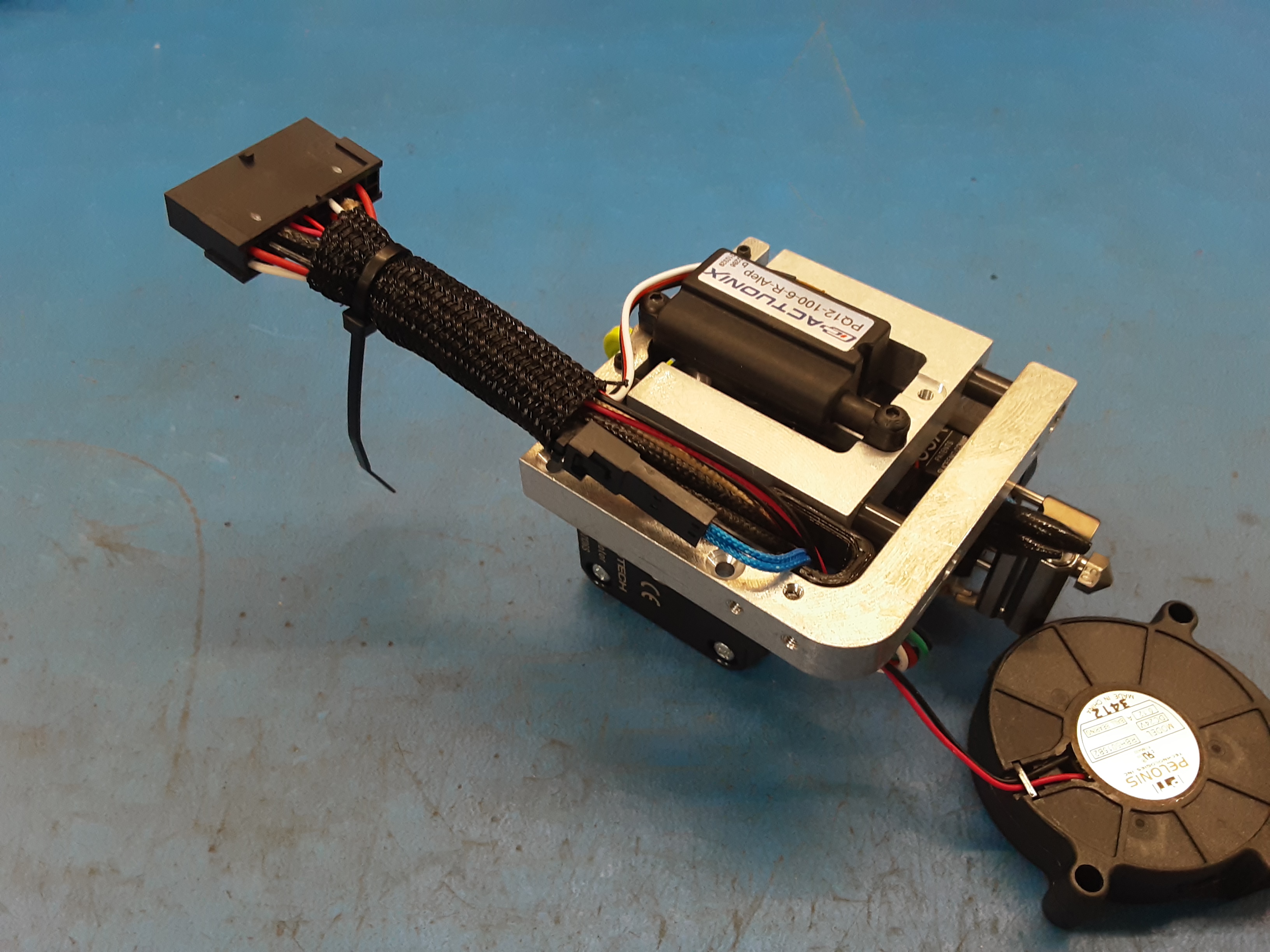
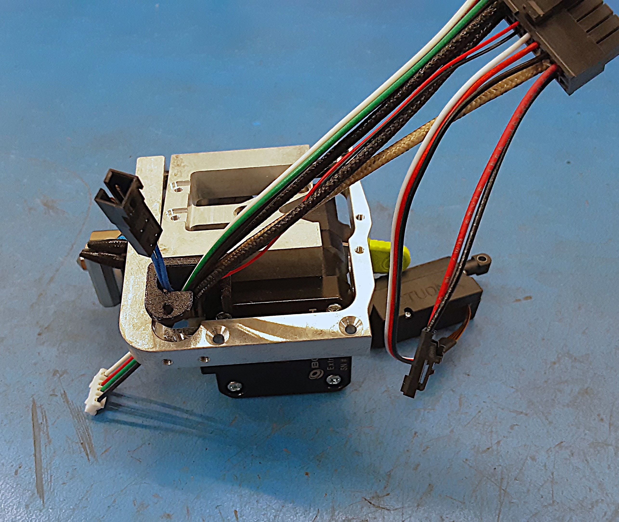
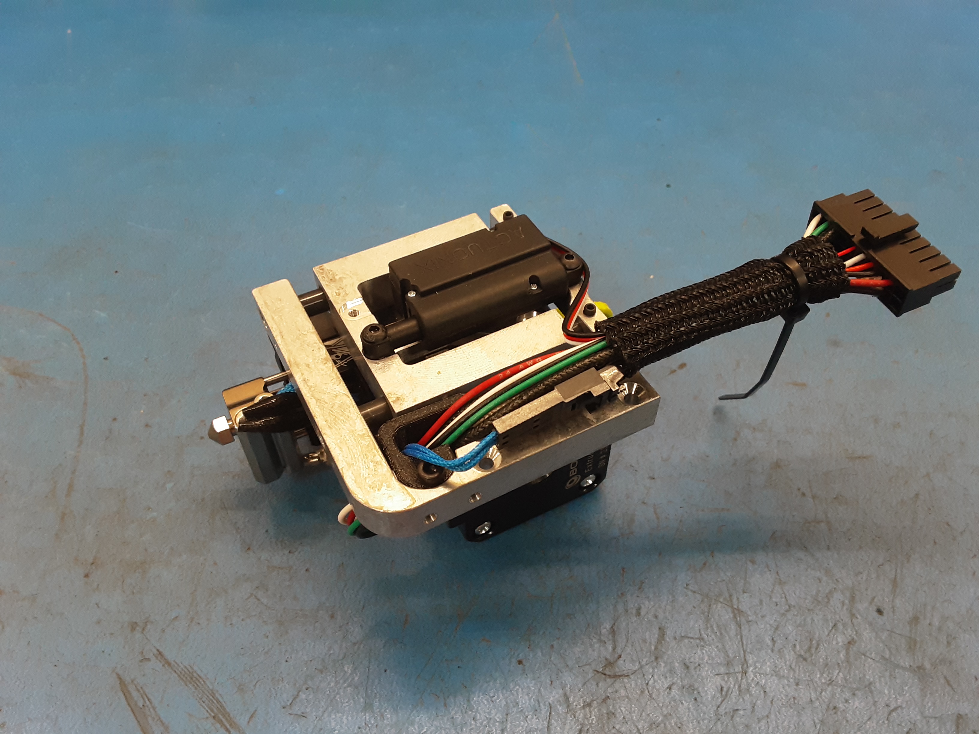
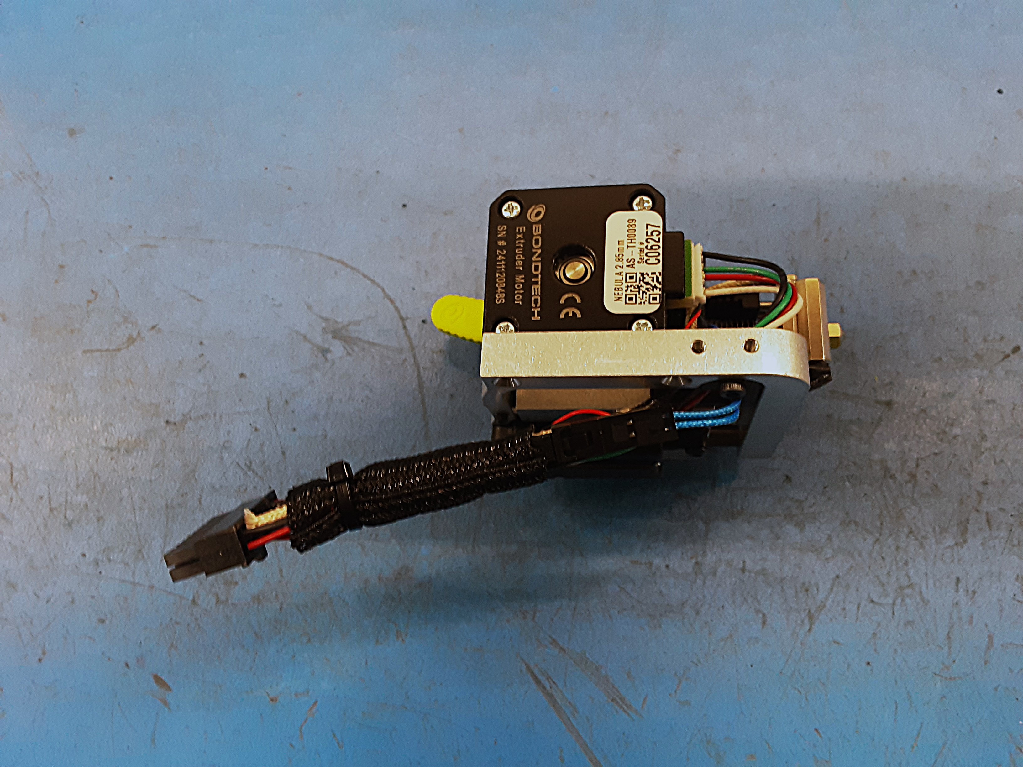
5R) Reattach the braiding around the wires and use 1x HD-MS0588 zip tie to secure the end.
5S) Put 1x DC-LB0160 serial number sticker on the connector of AS-CB0210 as shown. Set this motor assembly aside for now.


6A) Remove the braiding from AS-CB0211 and attach the ground wire as shown using screw #1 from
HD-MS0100.
6B) Attach the small fan from AS-CB0211 in the orientation shown using 2x HD-BT0261.
6C) Install the heater cartridge from AS-CB0211 and EL-TH0015 and secure them using screw #1 from
HD-MS0100.
6D) Grab the black block #1.
6E) Use the black block #1 to help balance the tool head for the next few steps.
6F) Bend the ground wire, heater cartridge, small fan wire, and EL-TH0015 down to follow PP-MP0345 to the motor. Have a 90 degree bend having the wires towards the motor plug.
6G) Attach PP-GP0746 using 2x HD-BT0007. Double check to make sure no wires are being pinched while tightening this part down.
6H) Loosely attach PP-FP0244 to the motor using 2x HD-BT0137 and 2x HD-WA0027.
6I) Using PP-FP0245 hook all the wires except for the actuator wires.
6J) Install 1x HD-RD0070 in the spot furthest from the wires. Use HD-BT0162 to secure the rod. Be careful not to force the rod in. The rod should sit flush with PP-FP0245 on the side with the set screw.
6K) Put all the wires except for the actuator wires in PP-GP0743.
6L) Attach PP-GP0743 using HD-BT0157. Double check to make sure the wires stayed in PP-GP0743.
6M) Install HD-RD0070 in the spot closest to the wires. Use HD-BT0162 to secure the rod. Be careful not to force the rod in. The rod should sit flush with PP-FP0245 on the side with the set screw. PP-FP0244 should slide back and forth fairly freely.
6N) Plug in the motor wire from AS-CB0211 into the motor.
6O) Grab the black block #2 and the “U” spacer.
6P) Put the “U” spacer on HD-RD0070 in between PP-FP0244 and PP-FP0245. With the motor assembly in the orientation shown slide the #2 block under the hot block. Make sure there are no wires in between the hot block and the #2 block as well as PP-FP0245 and the table. While pushing down on the hot block and both sides of PP-FP0245 tighten both HD-BT0137 screws in PP-FP0244.
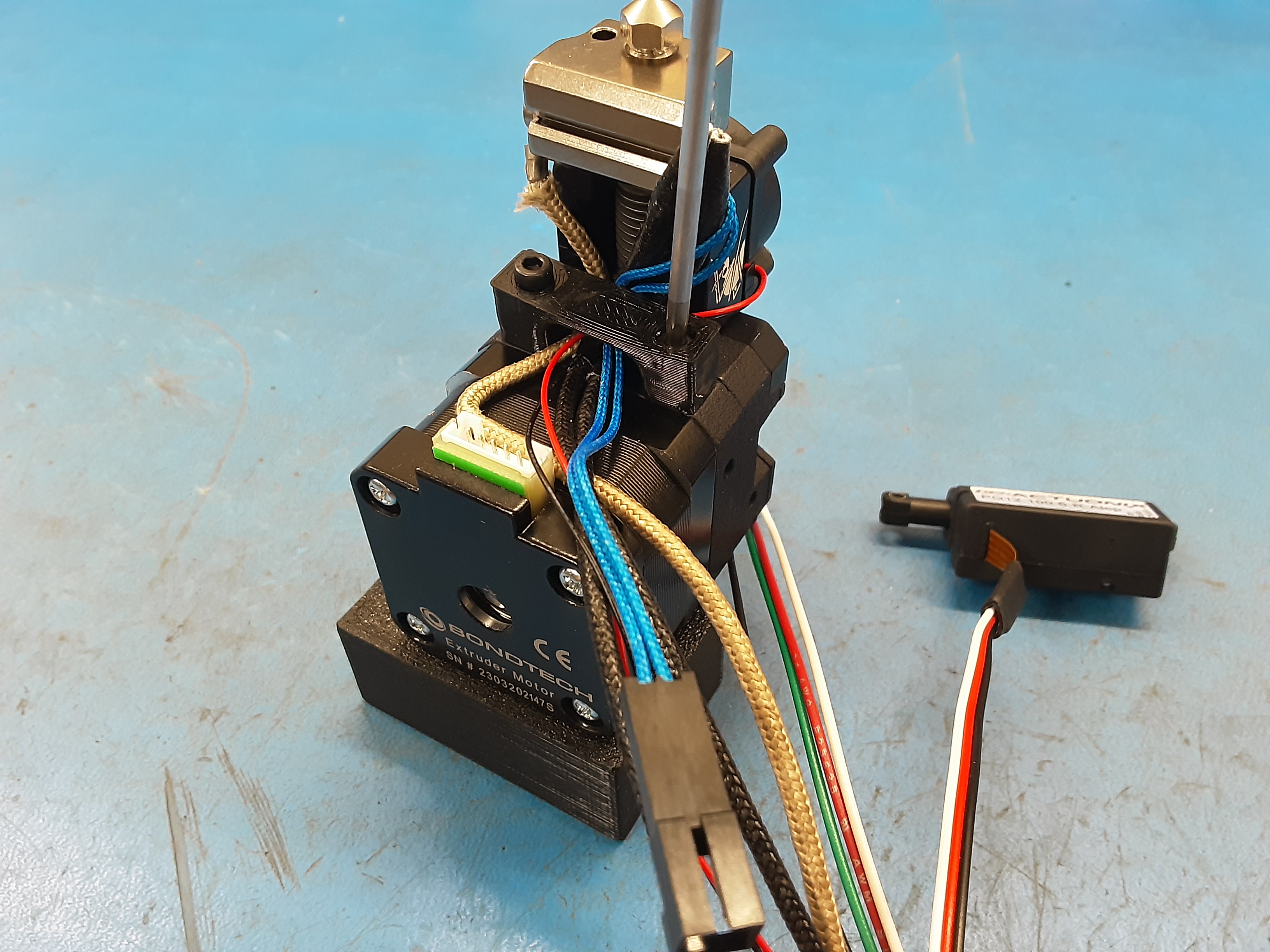
6Q) Attach the actuator to PP-FP0244 and PP-FP0245 using 2x HD-BT0137 screws.
6R) Reattach the braiding around the wires and use 1x HD-MS0588 zip tie to secure the end.
6S) Put 1x DC-LB160 on the bottom of the motor by the motor plug as shown.

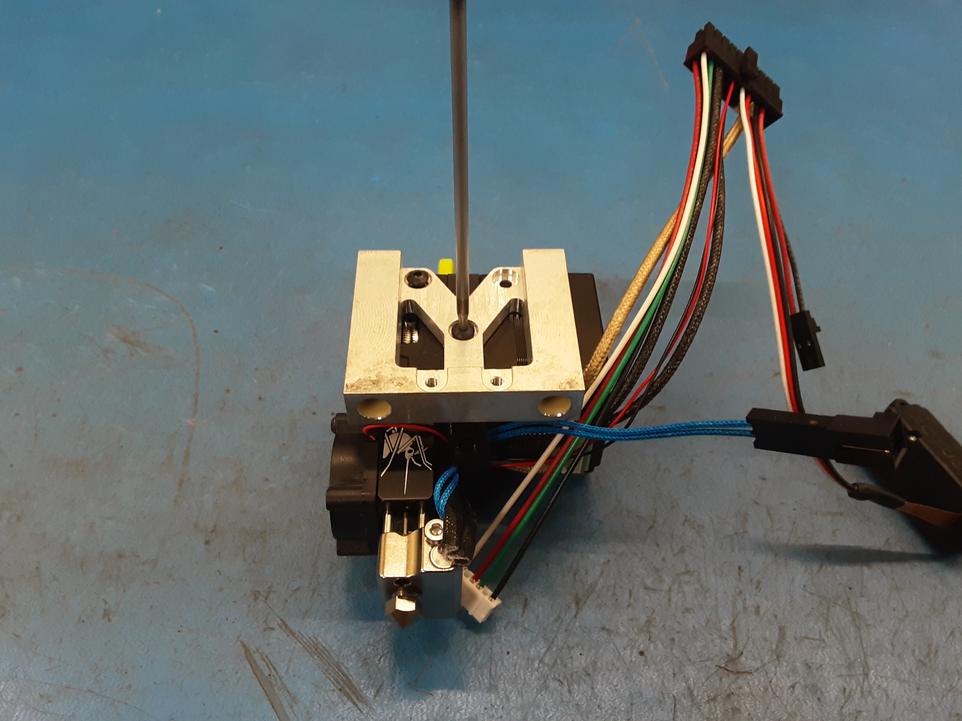
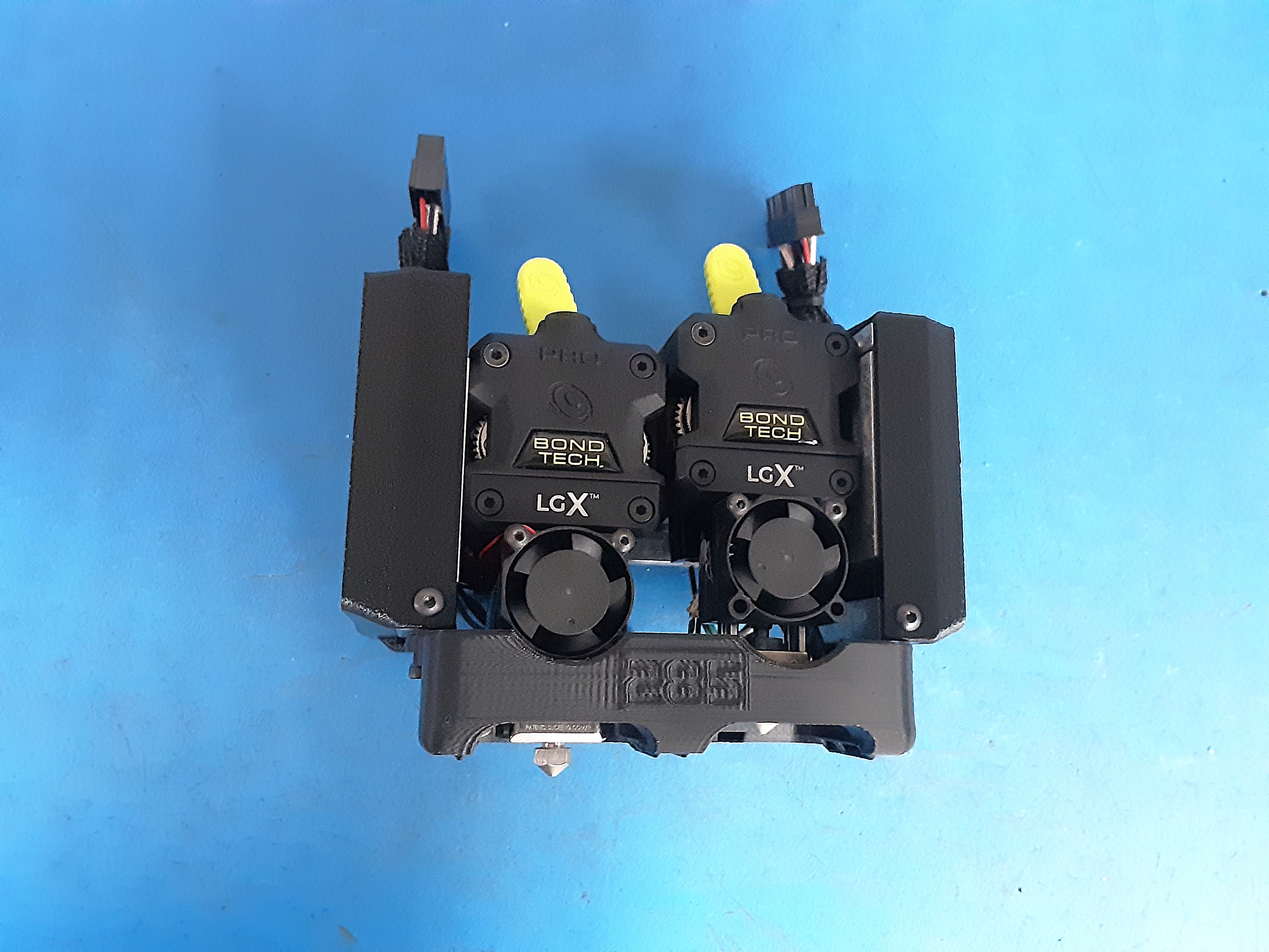
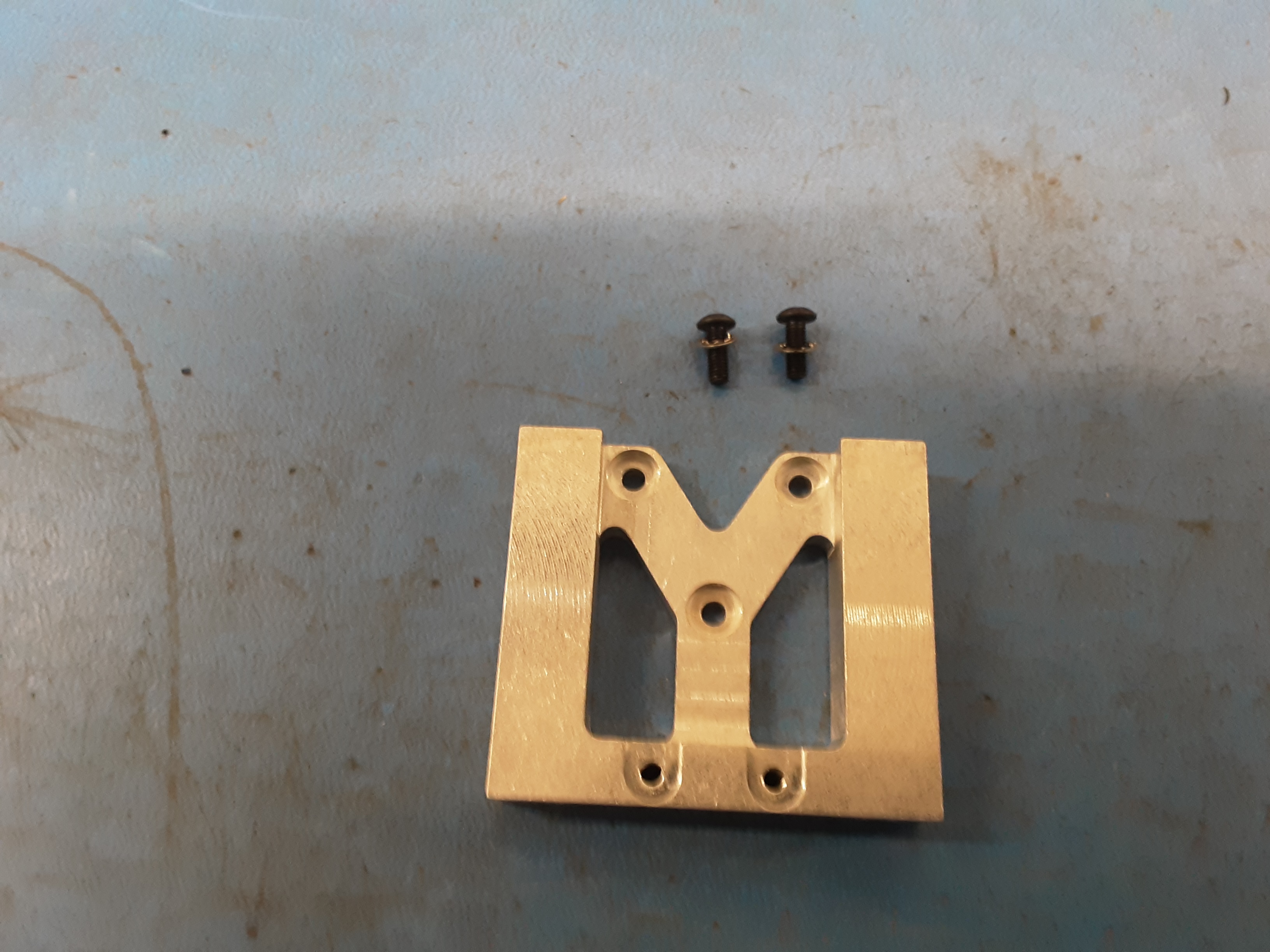
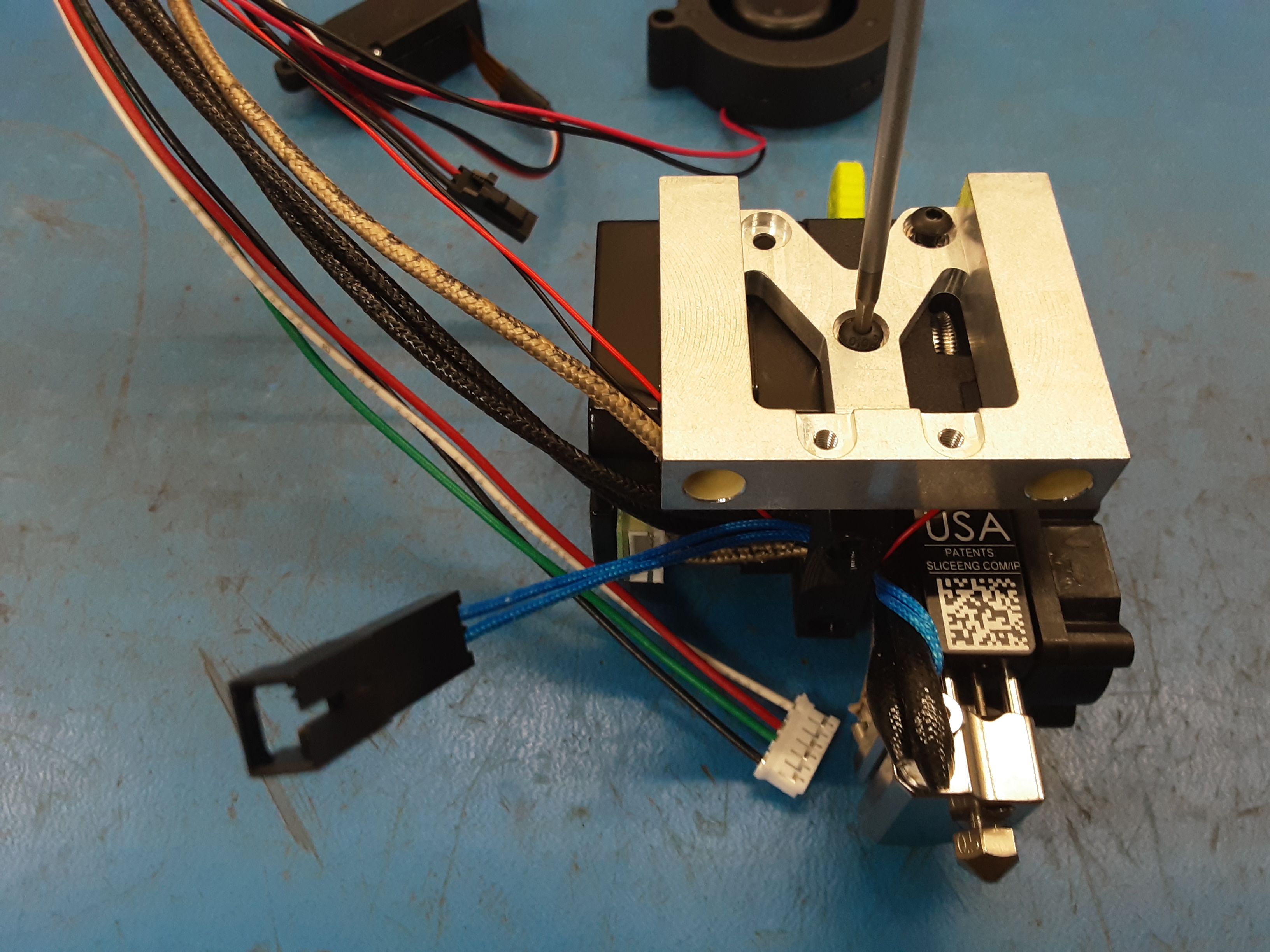
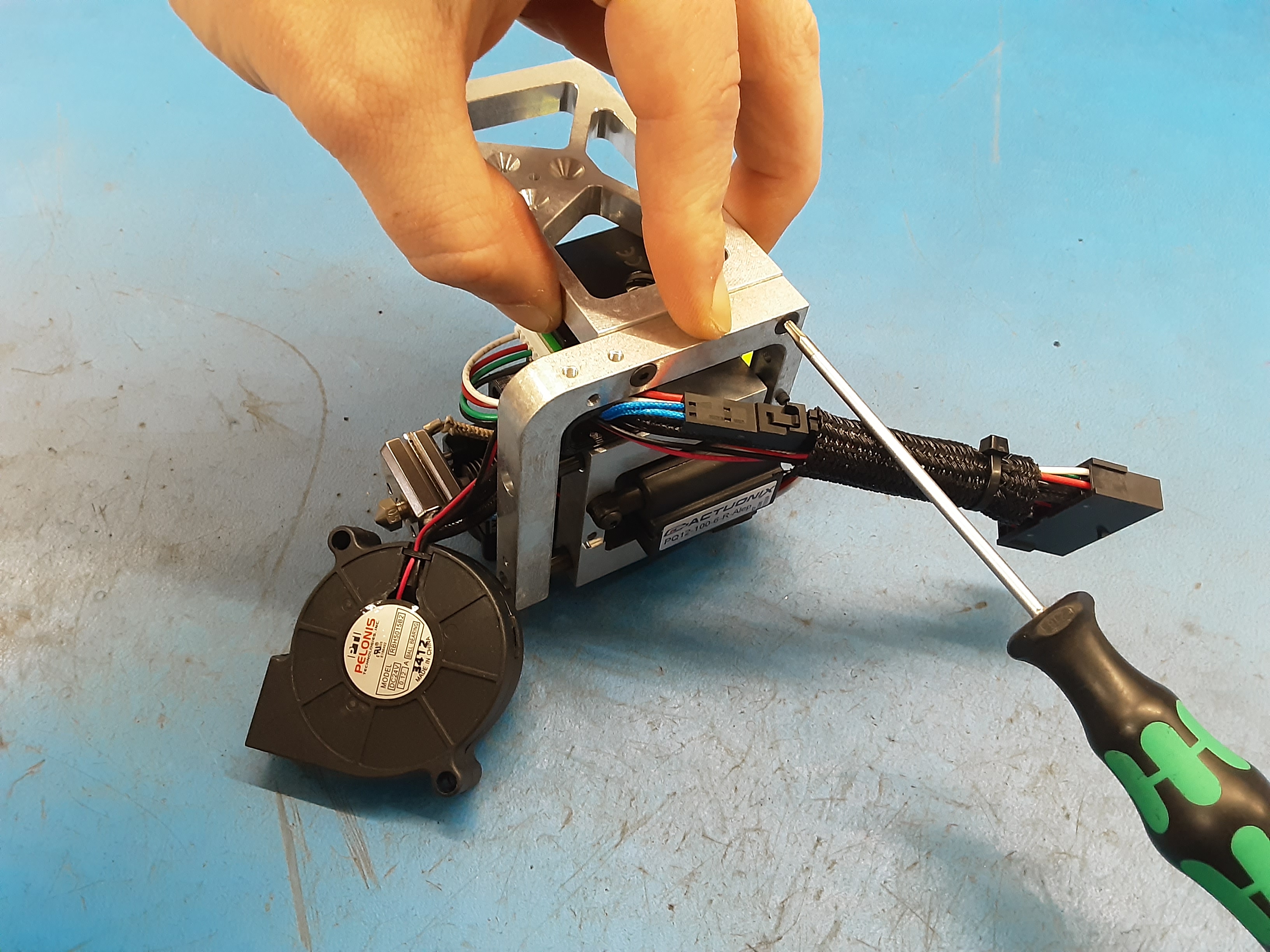
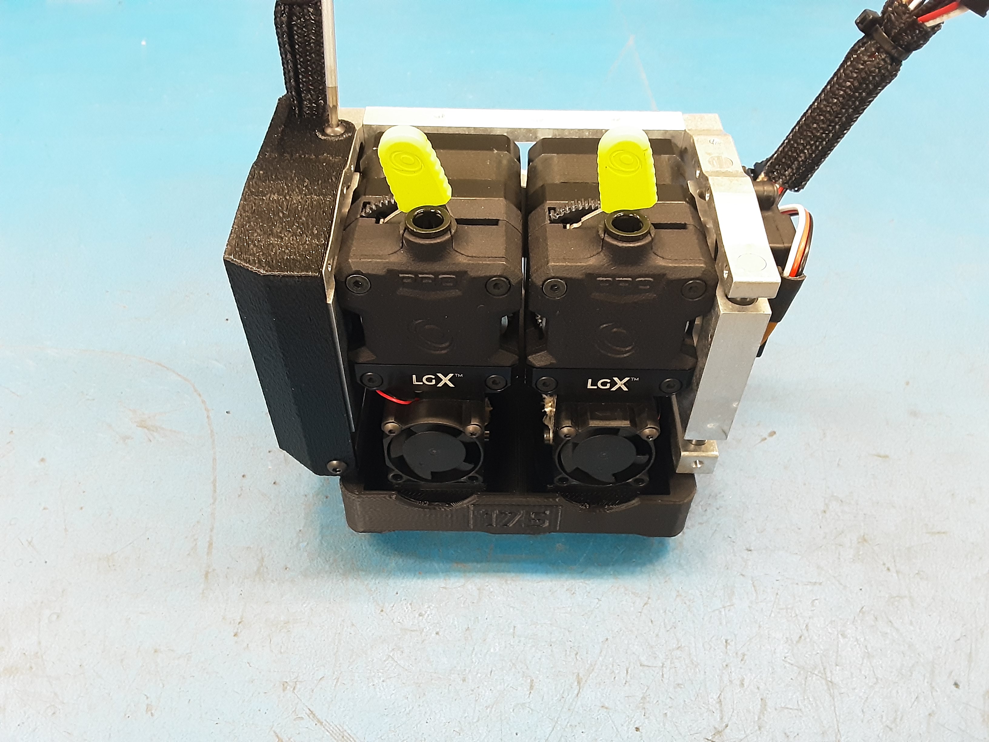
7A) Attach the Right Motor Assembly PP-FP0245 to PP-FP0246 using 2x HD-BT0118. While tightening the screws lift up on PP-FP0246 while pushing down on PP-FP0245 to help square up the parts.
7B) Attach the Left Motor Assembly PP-FP0245 to PP-FP0246 using 2x HD-BT0118. While tightening the screws lift up on PP-FP0246 while pushing down on PP-FP0245 to help square up the parts.
7C) Attach PP-GP0764 (PP-GP0740 for TN175) using 2x HD-BT0005.
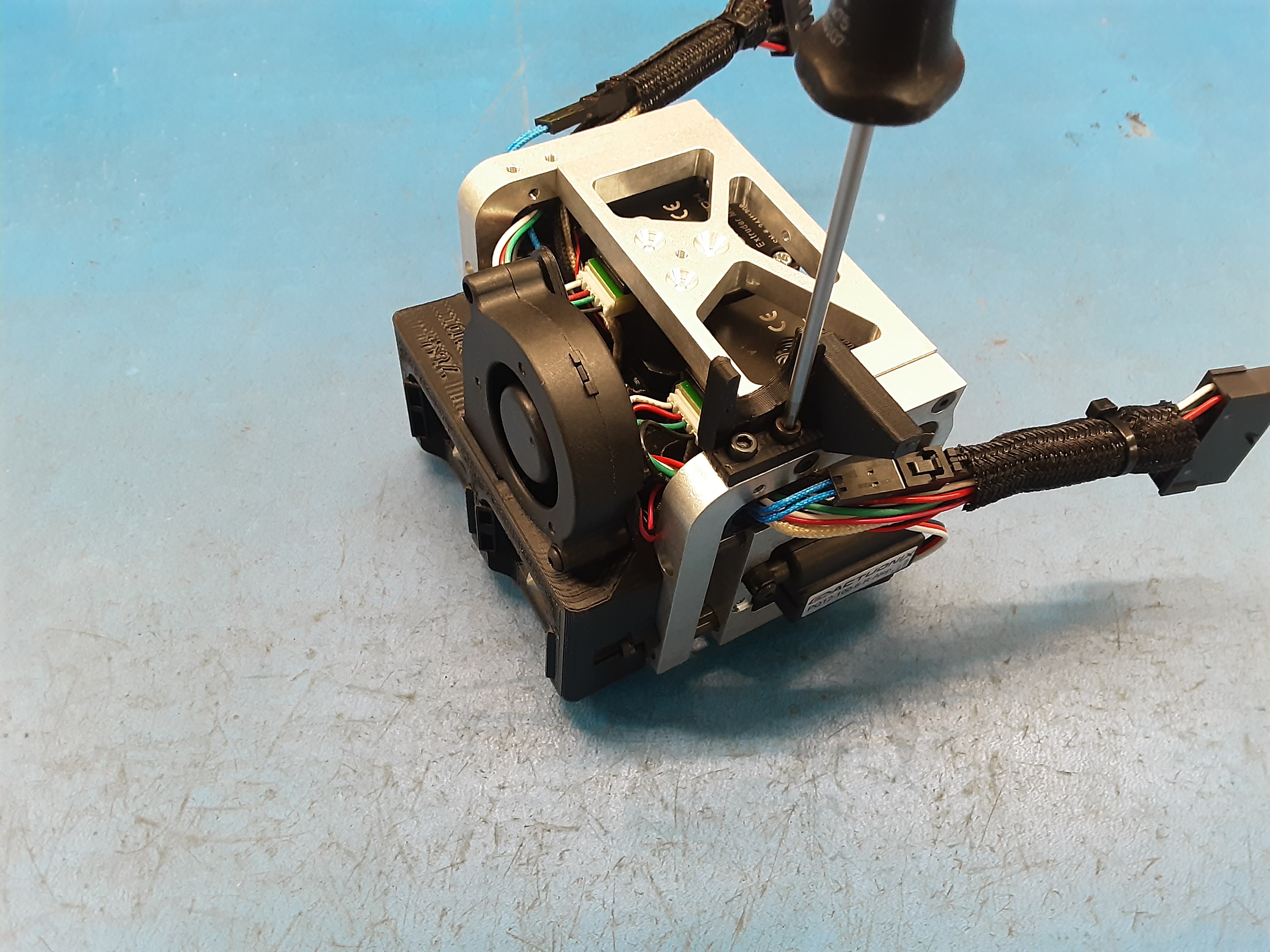
7D) Insert the blower fan from AS-CB0210 into the blower shroud and attach using HD-BT0171 and
HD-WA0038. Make sure the fan sits flat on the blower shroud while tightening the screw.
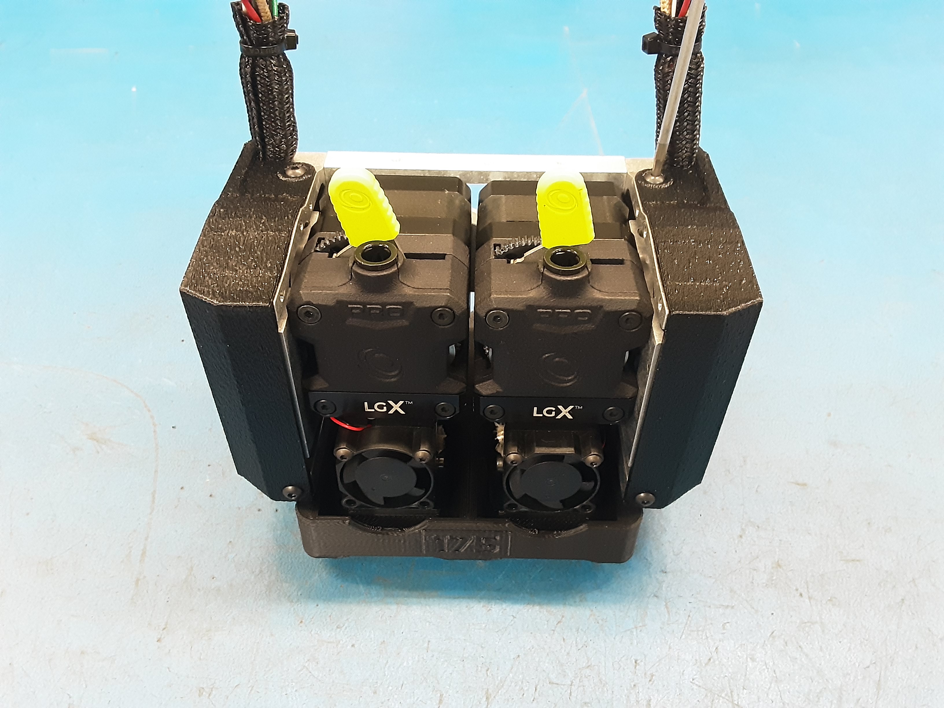
7E) Attach PP-GP0744 on the Left Motor Assembly PP-FP0245 using 2x HD-BT0157.
7F) Attach PP-GP0742 on the Left Motor Assembly PP-FP0245 using 2x HD-BT0140.
7G) Attach PP-GP0741 on the Right Motor Assembly PP-FP0245 using 2x HD-BT0140.
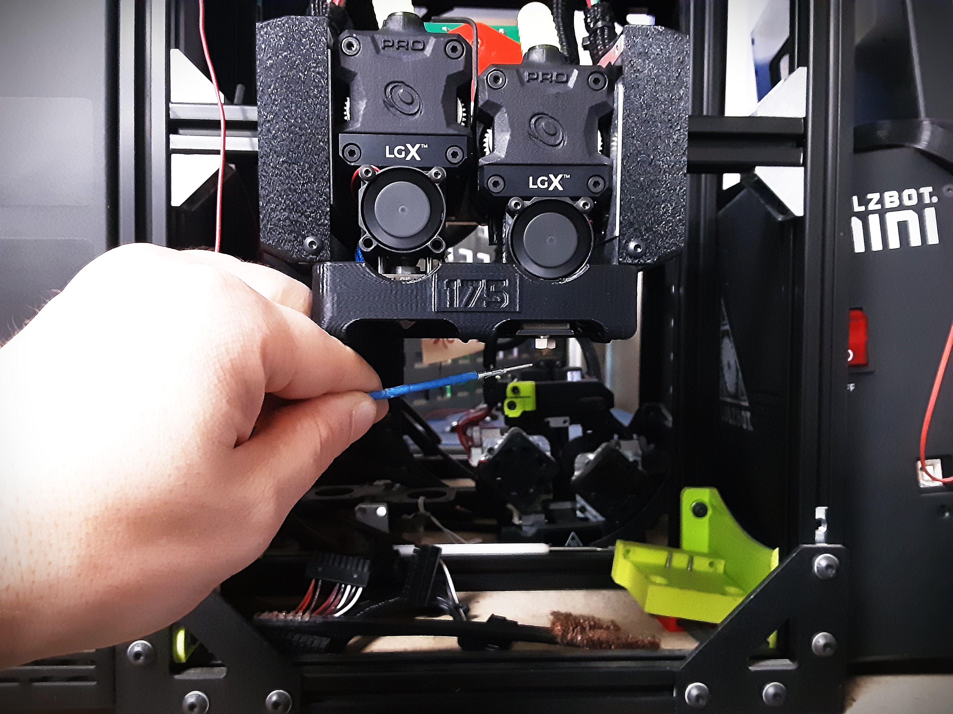
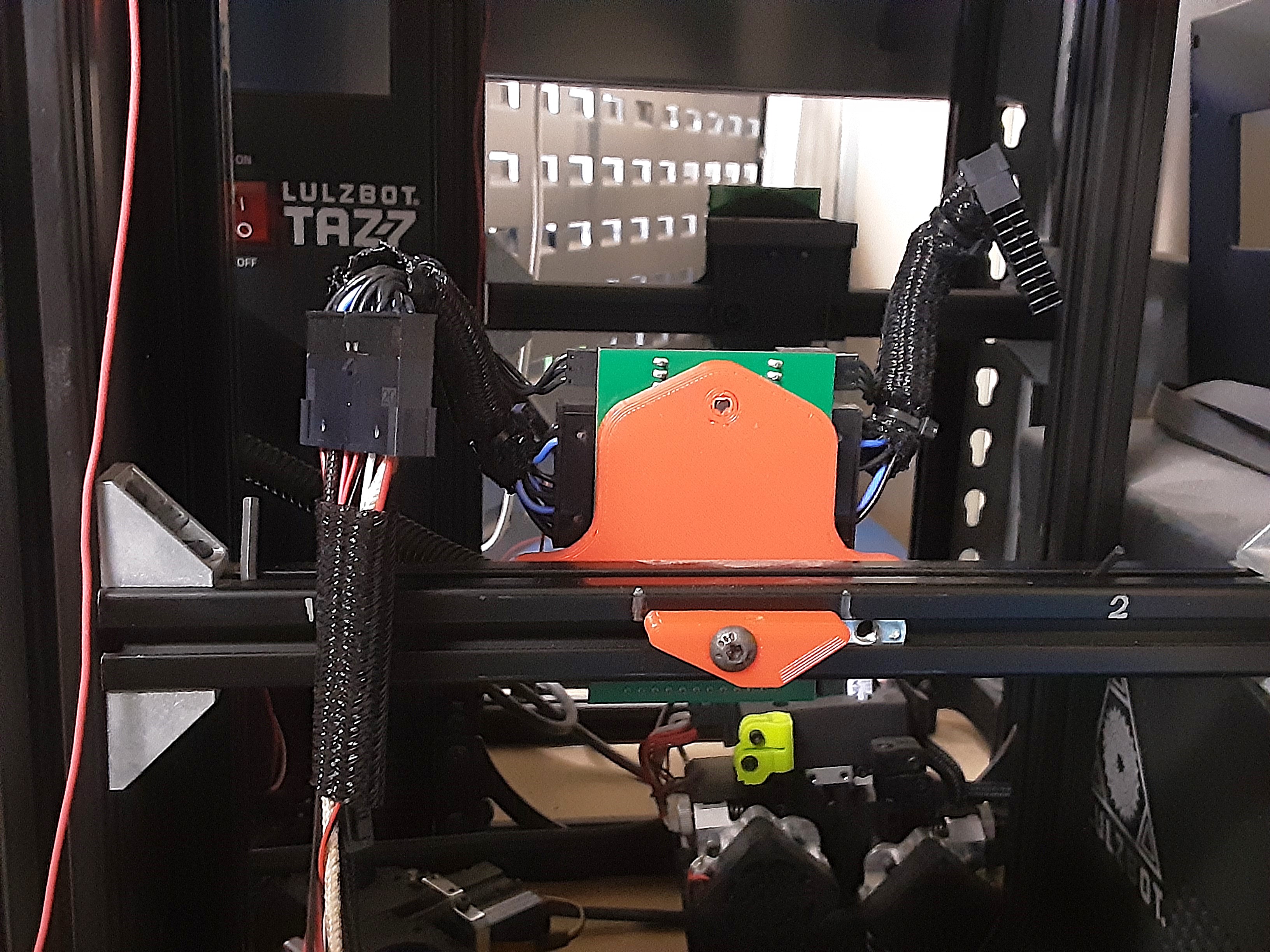
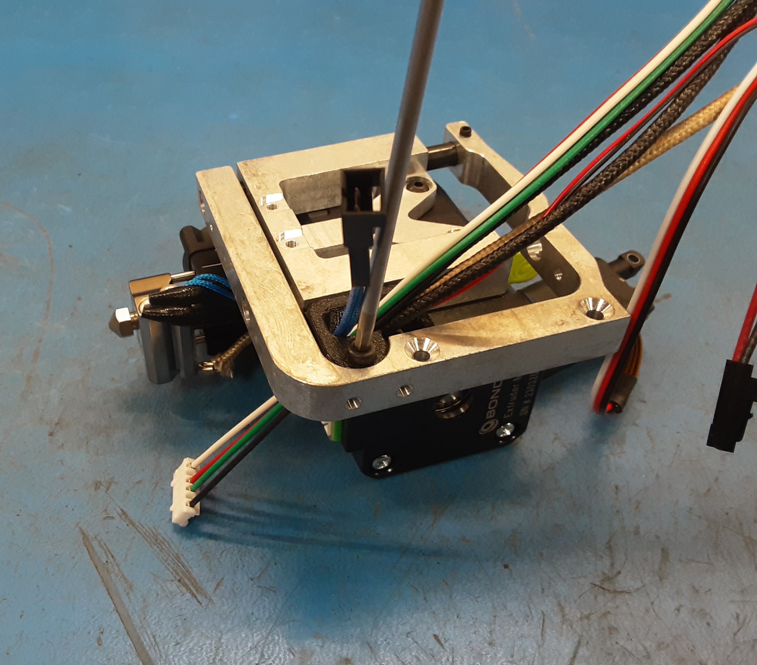
8A) Attach the tool head to the test printer by placing the PP-FP0246 over the red block on the test printer and inserting the small allen wrench through the middle hole on the top of PP-FP0246. Then plug in AS-CB0210 and AS-CB0211 into the jumper cables.
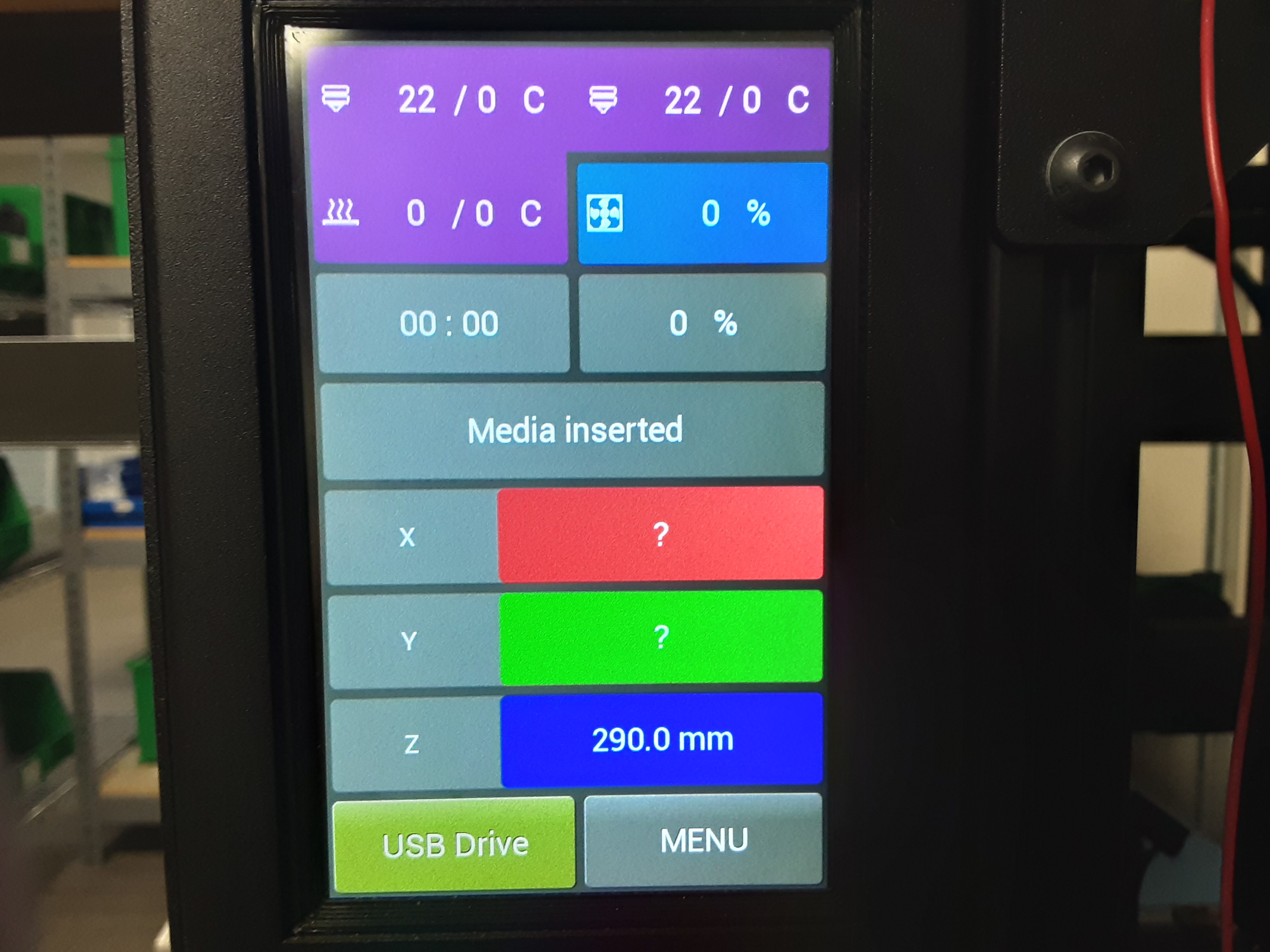
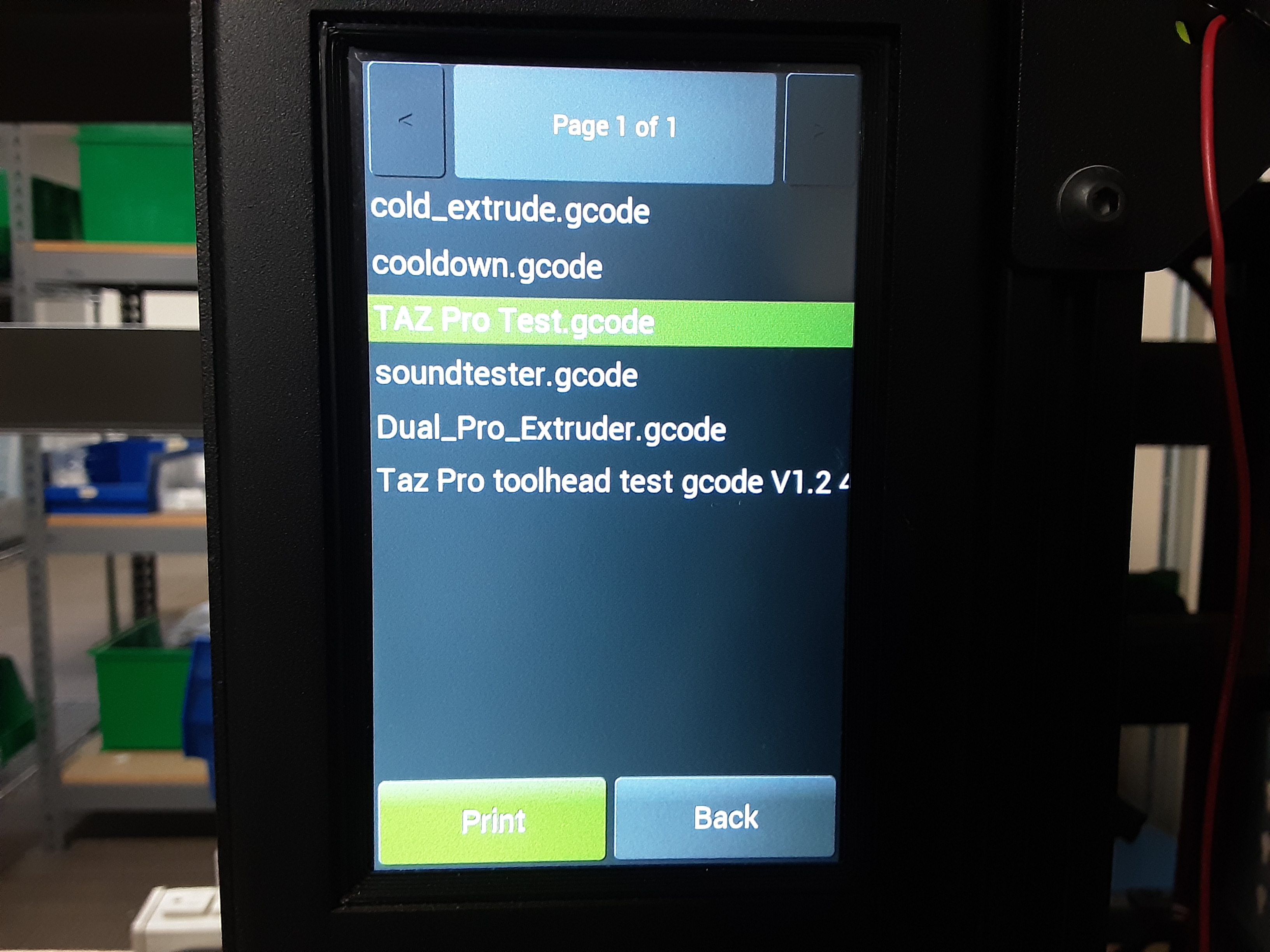
8B) Turn on the test printer select “USB Drive”
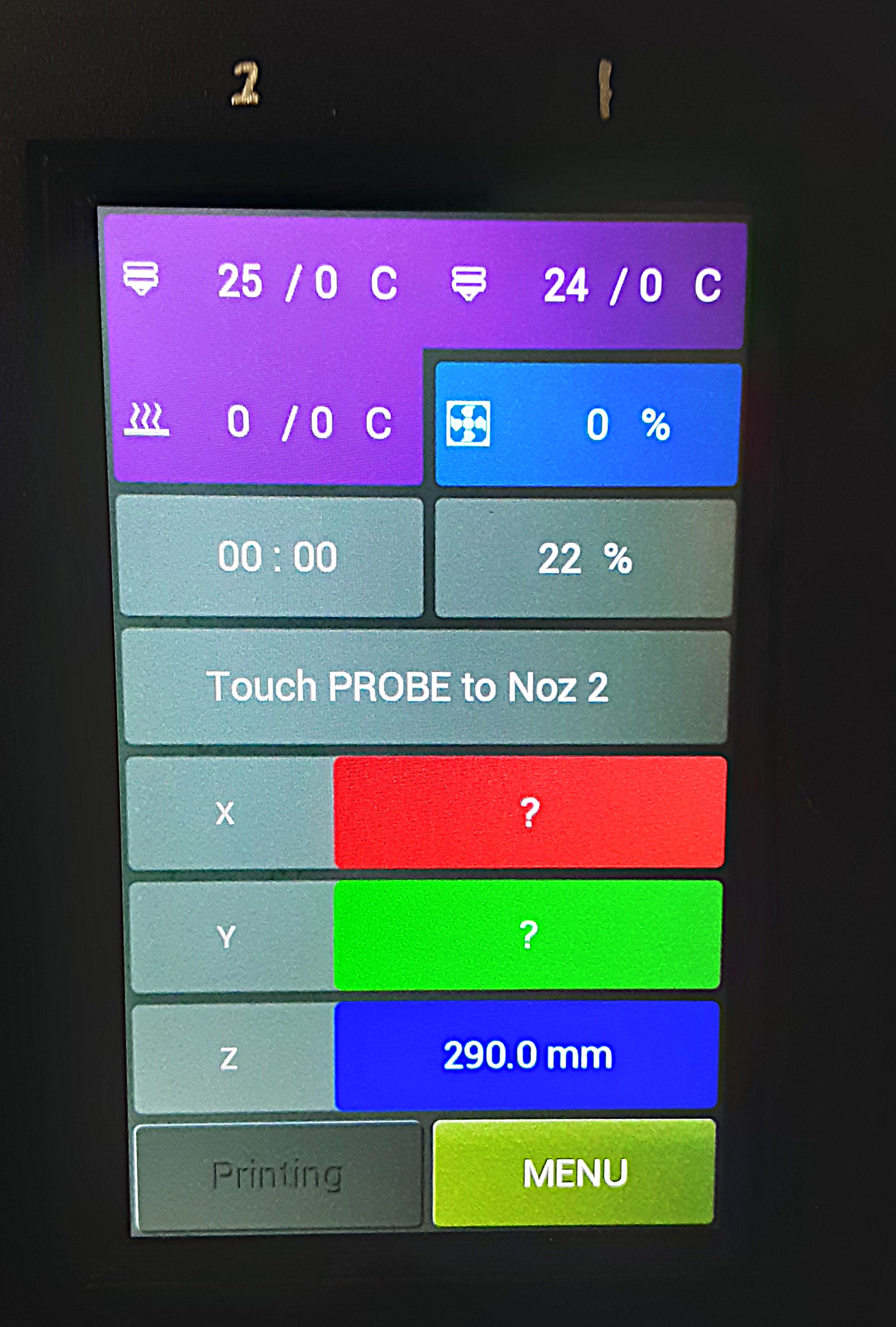
8C) Select “Taz Pro Test.gcode” and hit “Print”
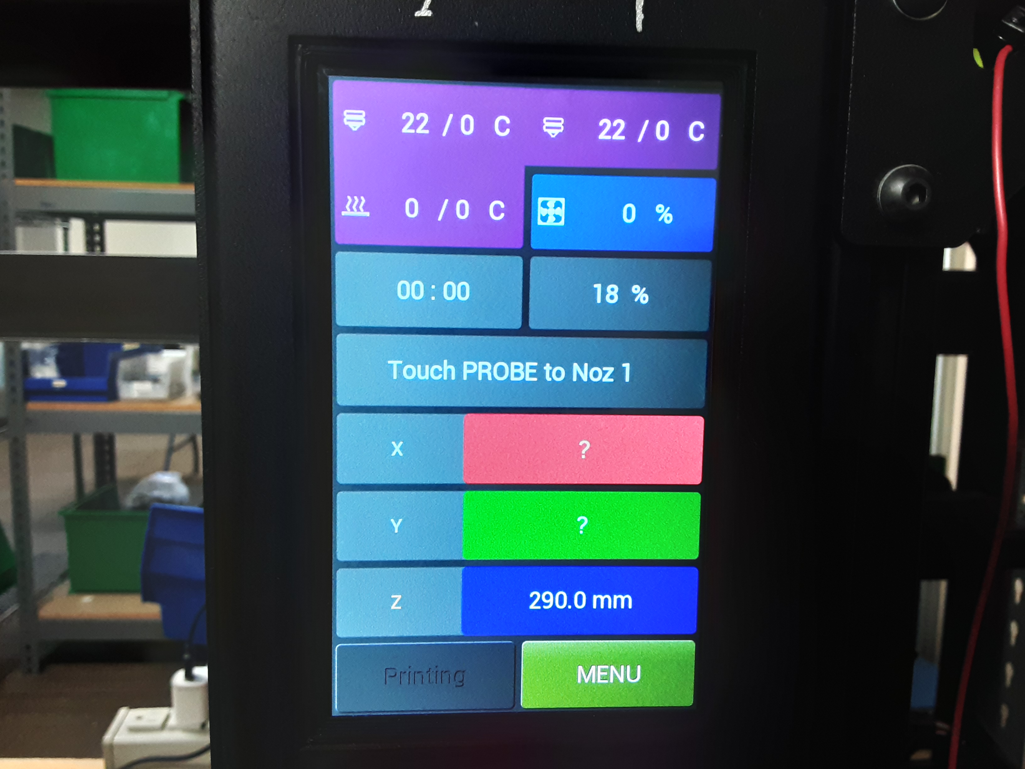
8D) Prompted to “Touch PROBE to Noz 1”
8E) Take the probe and tap it on the left nozzle.
8F) Prompted to “Touch PROBE to Noz 2”
8G) Take the probe and tap it on the right nozzle.
Note:
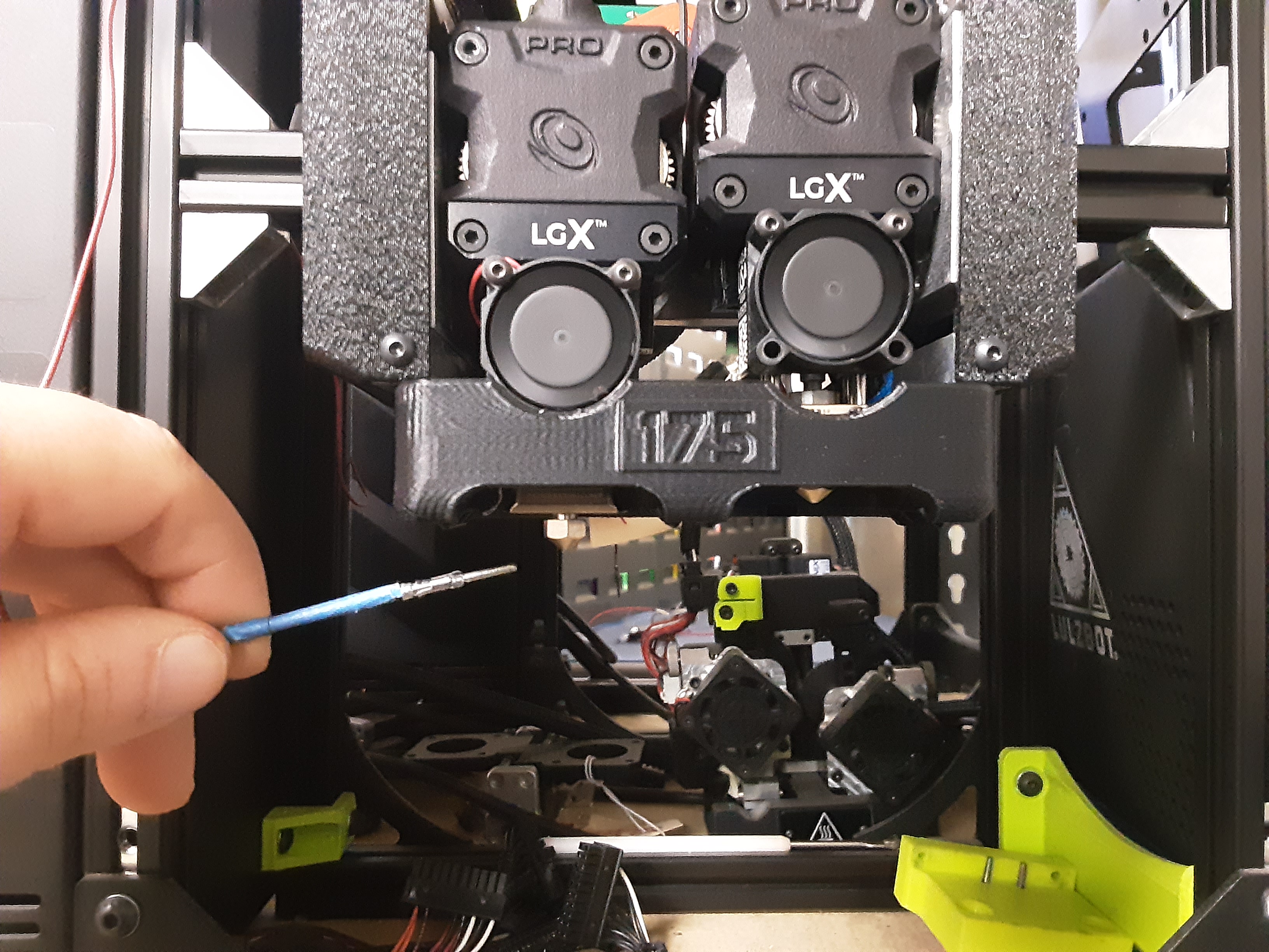
If testing a tool head for retail use new jumper (EL-HR0230 x1 and EL-HR0231 x1) cables during testing and send them with the tested tool head. While the tool head is testing make sure that the 2 small fans are on. When the actuators engage make sure that the PP-FP0244 slides bottom out on PP-FP0245 and no wires are getting pinched. Check that the motor on the side that is down is turning once the tool head is heated up. Once both motors have cycled the blower fan will kick in to cool down the tool head. Check that the blower fan is working.