Open HardwareAssembly Instructions
Guides for installation and assembly of the LulzBot line of products made by FAME 3D LLC.
Guides for installation and assembly of the LulzBot line of products made by FAME 3D LLC.
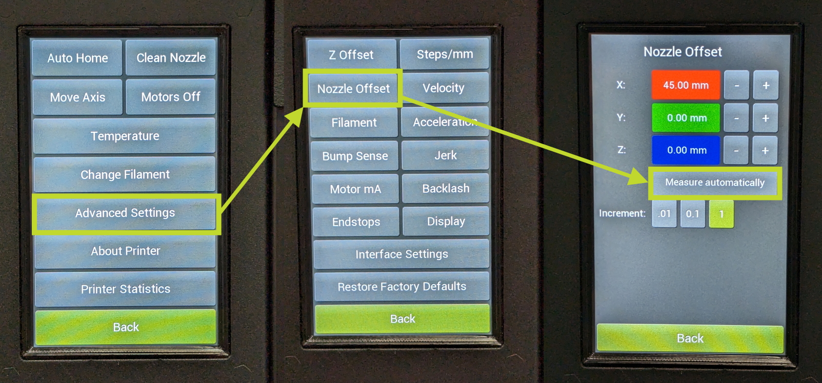
The TAZ Pro is able to calibrate its nozzle offset automatically using the Nozzle Offset Calibration on the printers LCD.
Ensure that you remove all filament from the printer and check that the wiper pads are clean and free of debris.
Navigate to the offset menu on the printers LCD and click measure automatically.
During this process, each nozzle will contact the calibration cube at the front of the print bed a number of times.
Watch to make sure that the nozzle does not push into the cube and stops the moment it contacts it.
If it does push into the cube, turn the print off and back on, clean the nozzle with a none conductive material, and restart the calibration process.
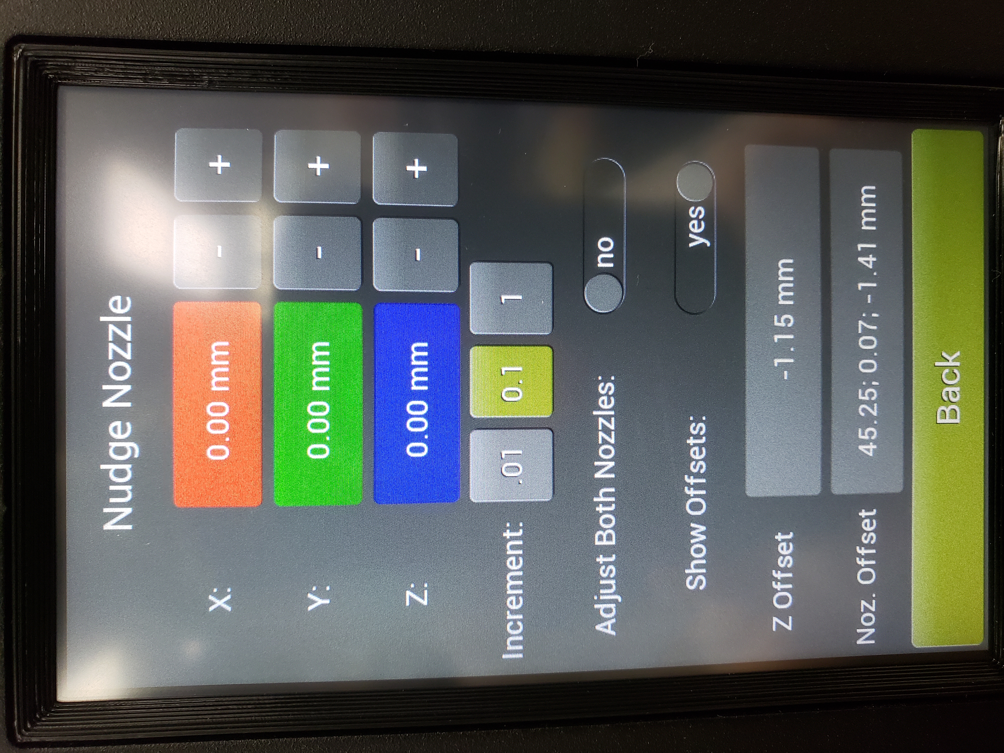
On Firmware earlier than 2.1.3.0.27, you will have the Nudge Nozzle Menu.
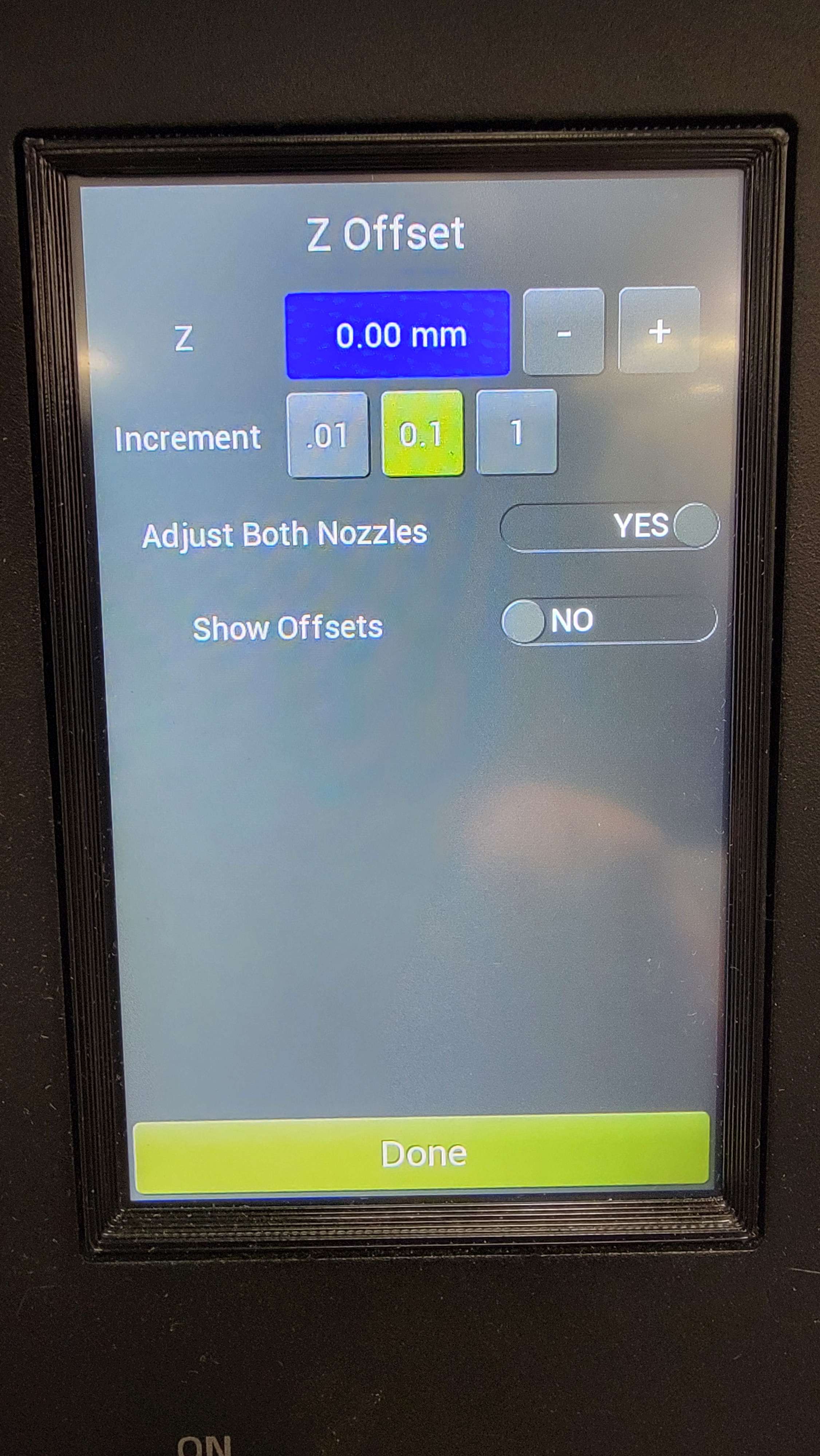
Newer firmware will simply be called Z Offset.
When the printer is laying down the first line, you can go into the LCD menu and select Z Offset/Nudge Nozzle.
Note that the Nudge Nozzle menu is only available during the printing process.
From here, select adjust both nozzles again and you can adjust the z-axis up or down accordingly. Doing this will adjust it in real time and you can see it change after making the adjustment.
Turn off adjust both nozzles and you will be able to adjust just the nozzle that is currently printing.
Once satisfied, click back and ensure that you click yes to save settings to default.
The runout sensor on the TAZ Pro will help ensure that no print is wasted in the event of a jam/lack of filament.
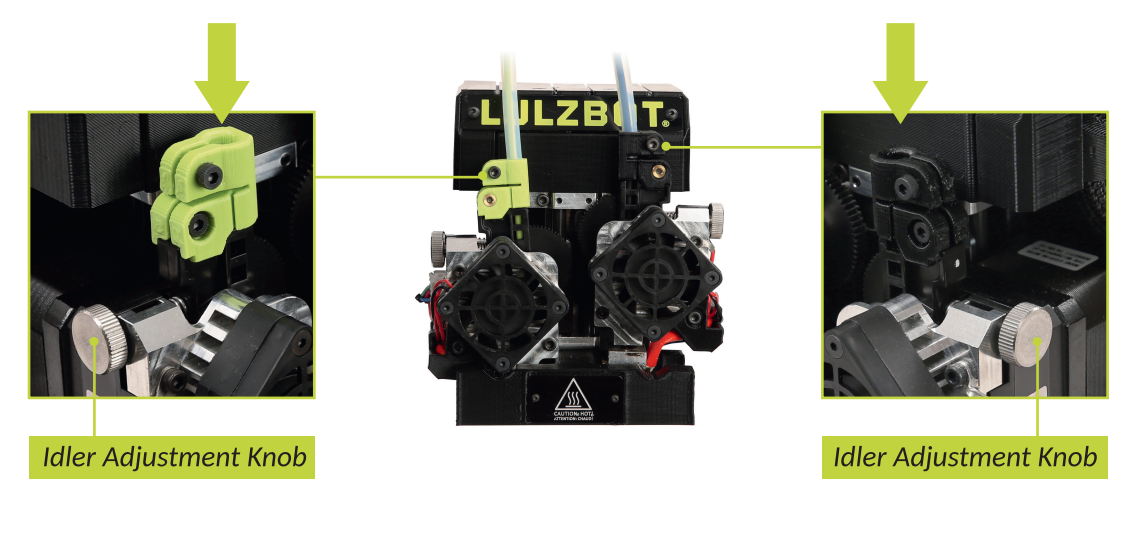
The PTFE guide tubes prevent strain on the tool head during printing to ensure it stays level with the print surface as well as allows the runout sensor to function properly.
It is essential to make sure the PTFE tubes are properly connected to both the runout sensor as well as the tool head itself.
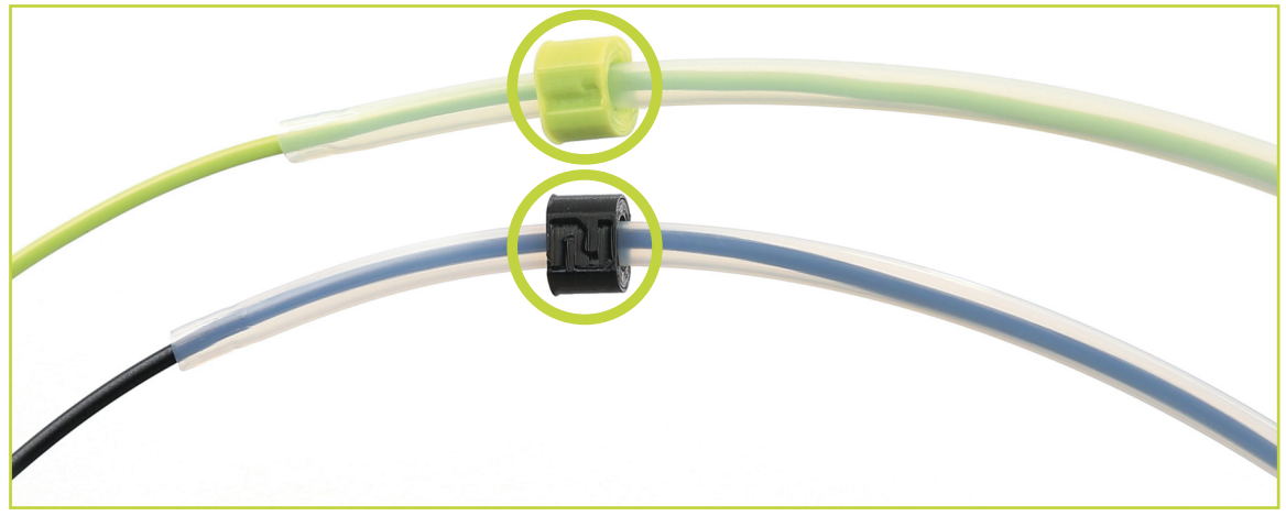
The runout sensor will have a green (Extruder 1) and black (Extruder 2) side.
The PTFE tubes will have a green and black color identifying which side it is plugged into.
The tool head guide tube clamps will also have a green and black side.
Ensure that all 3 of the colors match from the runout sensor to the tool head when feeding filament.
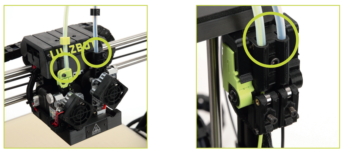
Feed the filament through the runut sensor and into the PTFE guide tube.
Continue feeding the filament until it exits the tube and proceed with feeding it into the correct extruder on the tool head.
Once it has been inserted into the tool head, reconnect the PTFE tube at the top of the tool head for both Extruders.

Prime towers help prime the nozzle before extrusion starts on the model.
Without the nozzle being primed, you may end up with holes in your model after the printer changes from 1 extruder to the other.
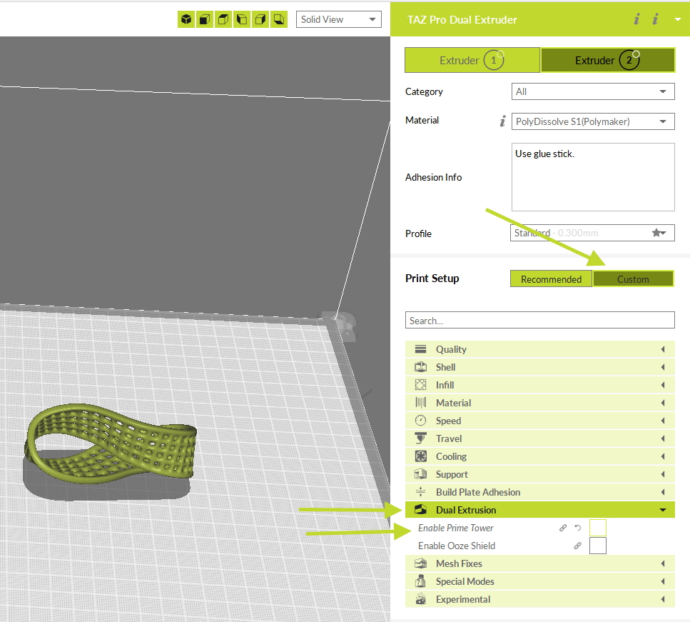
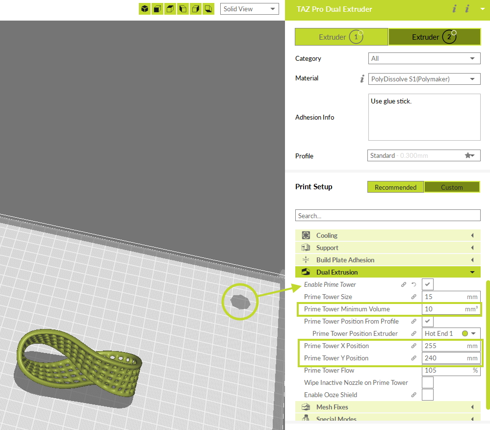
In your Prepare window in Cura, select Custom next to Print Setup and locate the Dual Extrusion options.
Expand this node.
Enable Prime Tower.
You will now see a round shadow appear on your build plate.
The Prime Tower Minimum Volume will be the amount of priming the nozzle will do prior to moving to the print. This will be different for Extruder 1 and Extruder 2. Be sure change between E1 and E2 to ensure both nozzles prime enough before moving to the print.
You can manually change the X and Y location of the tower by adjusting the X and Y position settings.
You want this to be near the print to prevent oozing during the movement from the tower to the print.
When one model has been split into separate models, you may need to merge them back together for dual printing.
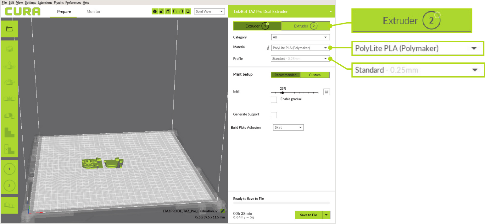
In the Prepare sidebar on the right side of the screen, confirm that PolyLite PLA (Polymaker) is selected for Material and Standard is selected for the Profile to be used for printing on Extruder 1. Click on the Extruder 2 button and confirm that Polylite PLA (Polymaker) and Standard are selected for Extruder 2.
By default, your models will print using Extruder 1.
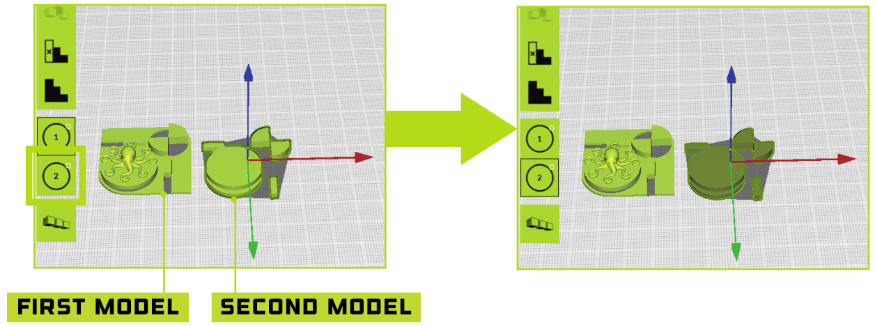
Click on the model you wish to print using the secondary extruder on the virtual print bed, then click on the 2 on the left side of the print area.
This designates that second model as the piece to be printed with extruder 2.
The model will change color based on the filament selected for extruder 2 to reflect the change.
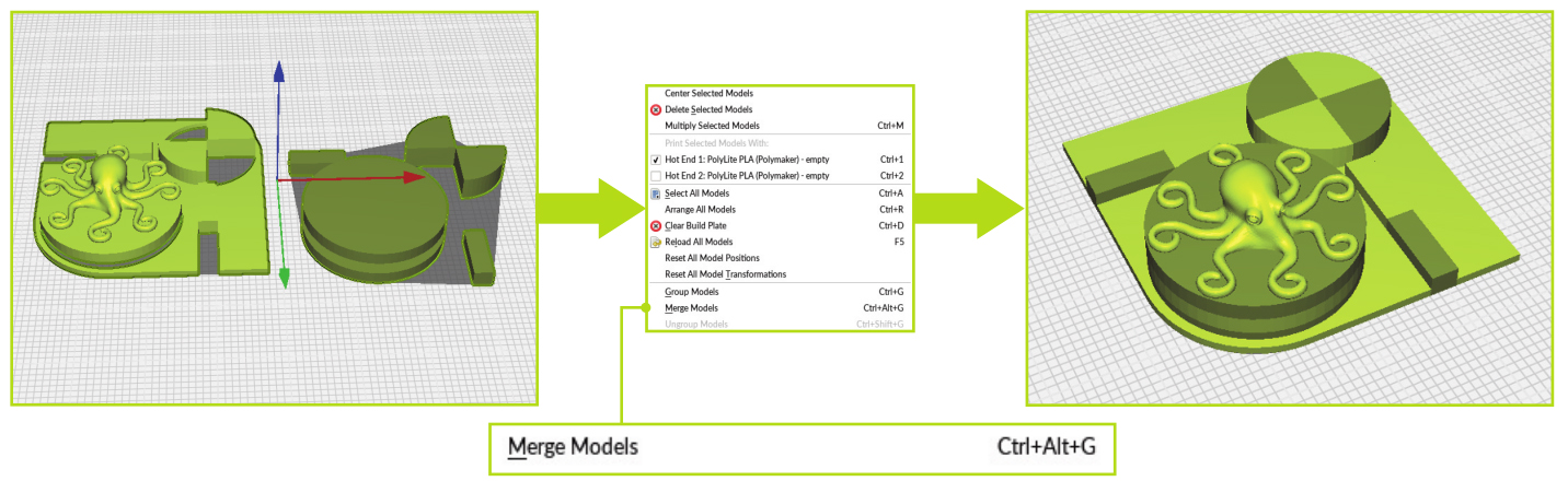
With one model selected, hold shift and click on the secondary model to select both models.
Right click on your first model and select Merge Models from the dropdown menu to combine the models into a single print.
Important
Ensure that whatever filament you are using as a breakaway or dissolvable support material is dry.
Leaving filament out, even overnight, is enough to cause it to absorb moisture and this can create printing issues.
It is recommended to print from a drybox or other climate controlled enclosure to help prevent filament deterioration.
Prepare your model
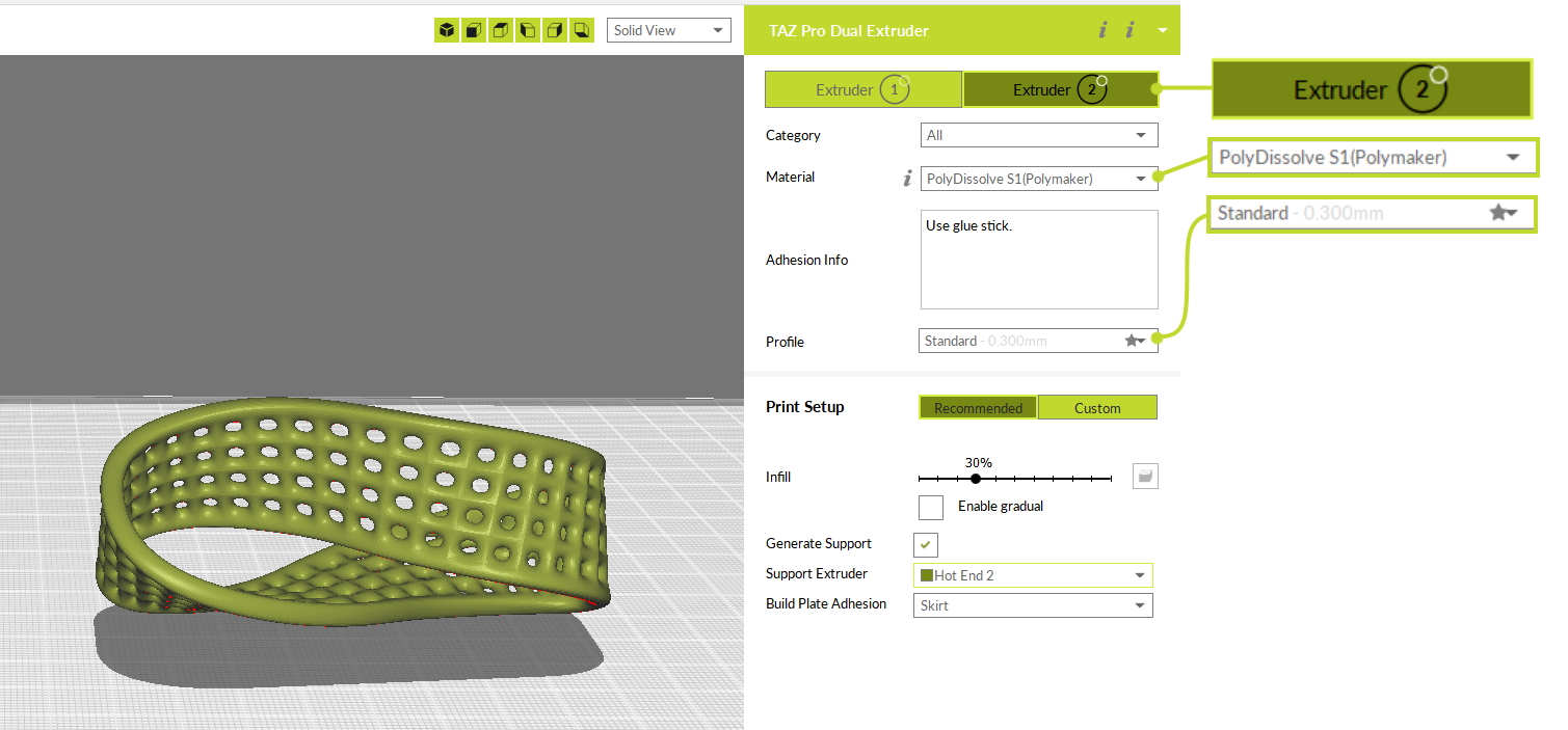
In the Prepare sidebar on the right side of the screen, confirm that PolyLite PLA (Polymaker) is selected for Material and Standard is selected for the Profile to be used for printing on Extruder 1. Click on the Extruder 2 button and confirm that your desired support material is selected and the Standard profile are selected for Extruder 2.
Click on the model you wish to print using the secondary extruder on the virtual print bed, then click on the 2 on the left side of the print area.
Check the Generate Support box and select Hot End 2 as the support extruder rather than assigning an object to Extruder 2.
Before printing, ensure that you are using some form of bed adhesion promotor, such as glue stick as indicated in the Adhesion Info section in Cura, located under Material.