Open HardwareAssembly Instructions
Guides for installation and assembly of the LulzBot line of products made by FAME 3D LLC.
Guides for installation and assembly of the LulzBot line of products made by FAME 3D LLC.
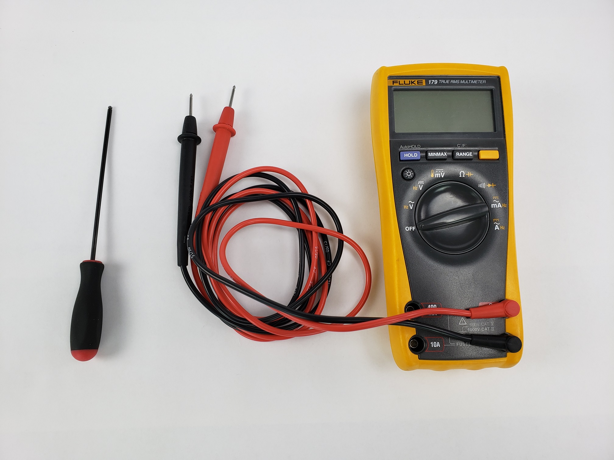
-Multimeter
-2.5mm hex driver if removing an x-carriage cap.
-Begin by confirming the printer is powered off and that the power cord and USB cable are disconnected.
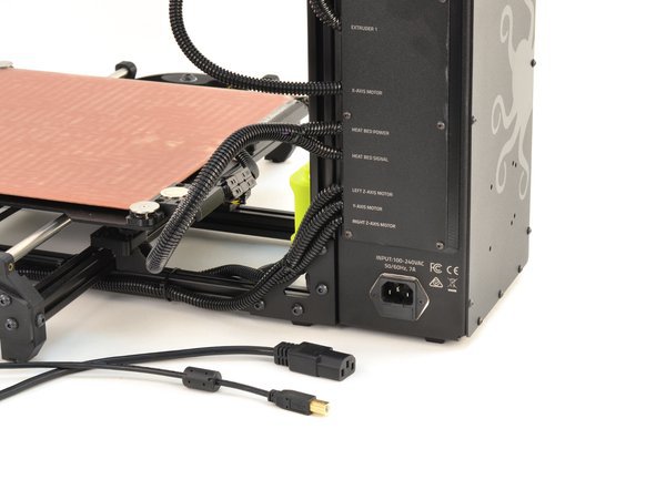
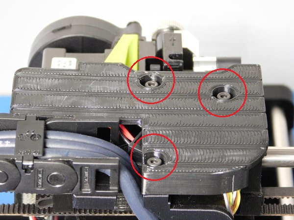
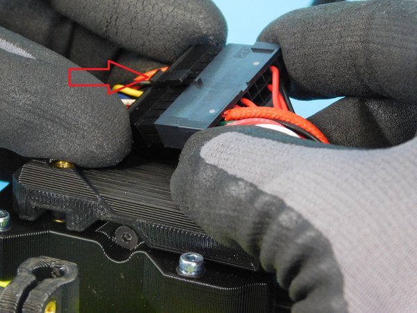
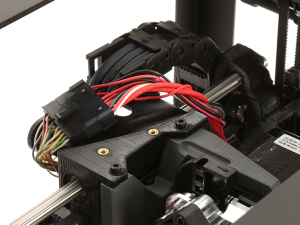
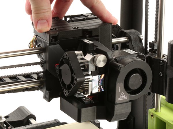
-If your printer has an x-carriage cap covering the tool head harness, remove it to expose the tool head harness.
-These are held in by a few M3 screws.
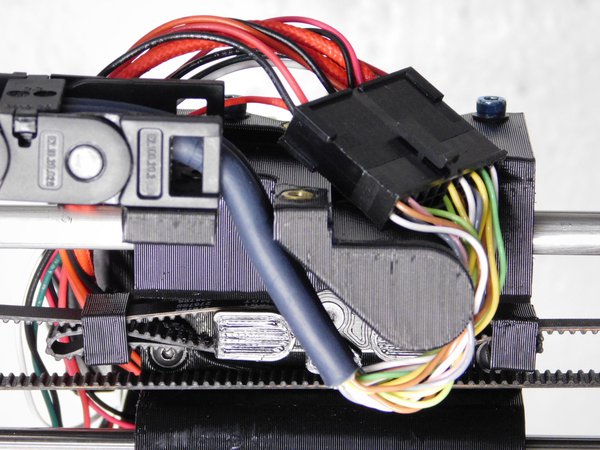
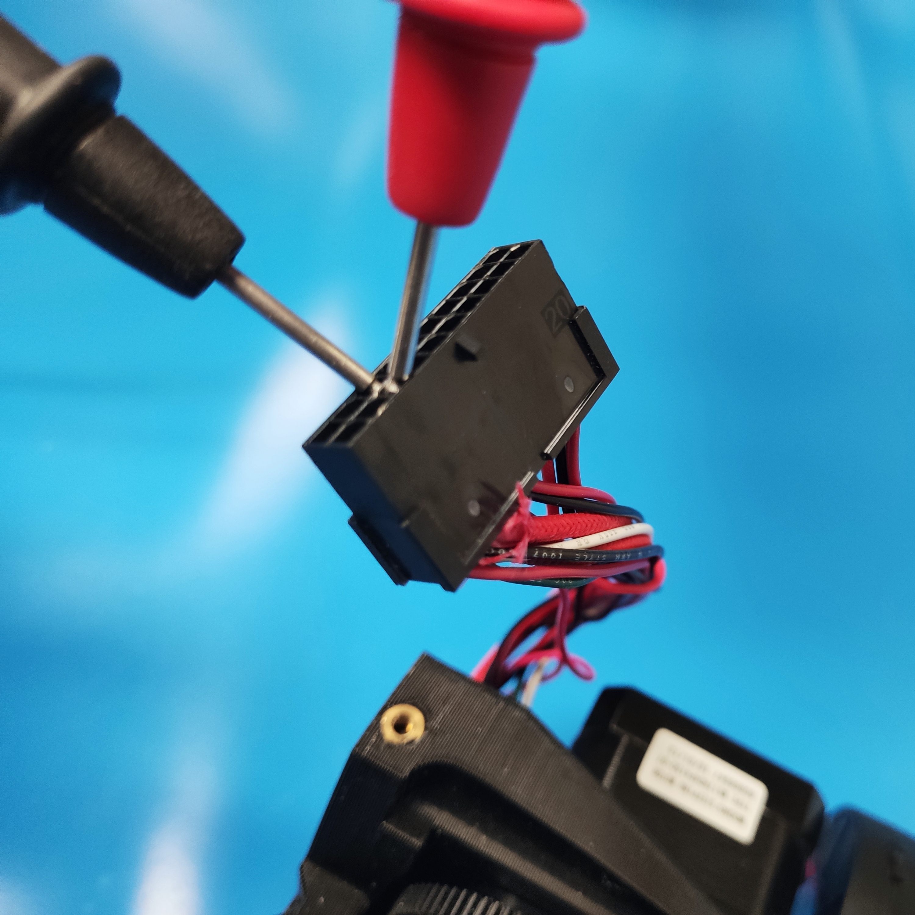
-Pinch the tab on the harness connector and gently wiggle the harness until it freely comes apart.
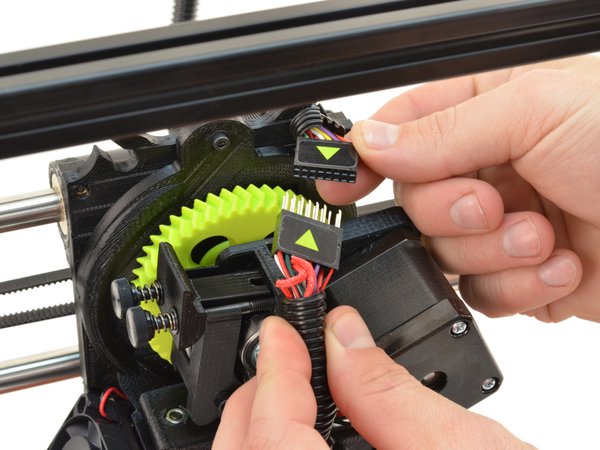
-For printers that have a molex connector without a tab, simply pull the connectors apart. These tool heads can be identified by a green arrow sticker on the molex connector.
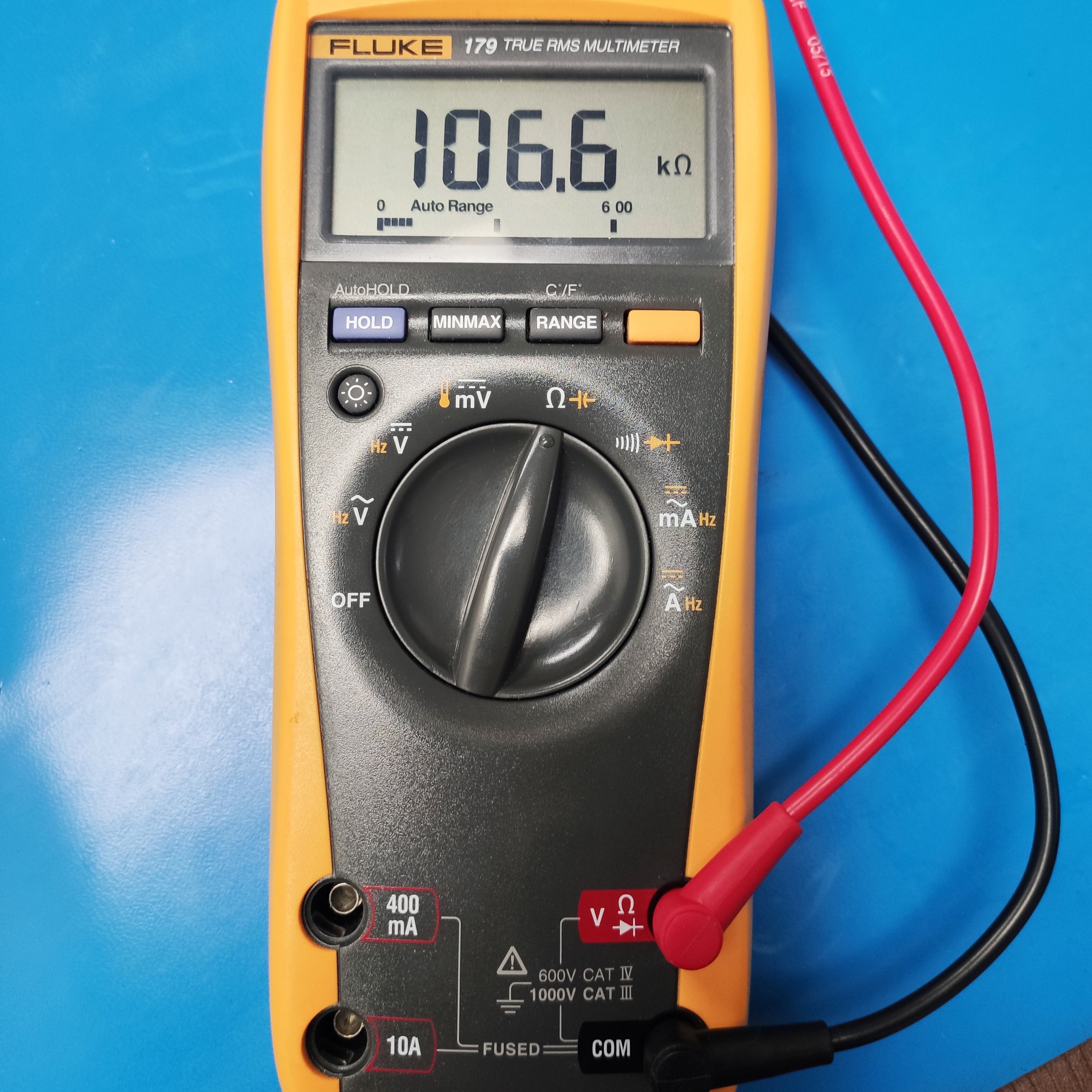
-Set your multimeter to read resistance as indicated by the ohm symbol “Ω”.
-If your multimeter is not auto ranging, set it to read a resistance value of 100k ohms.
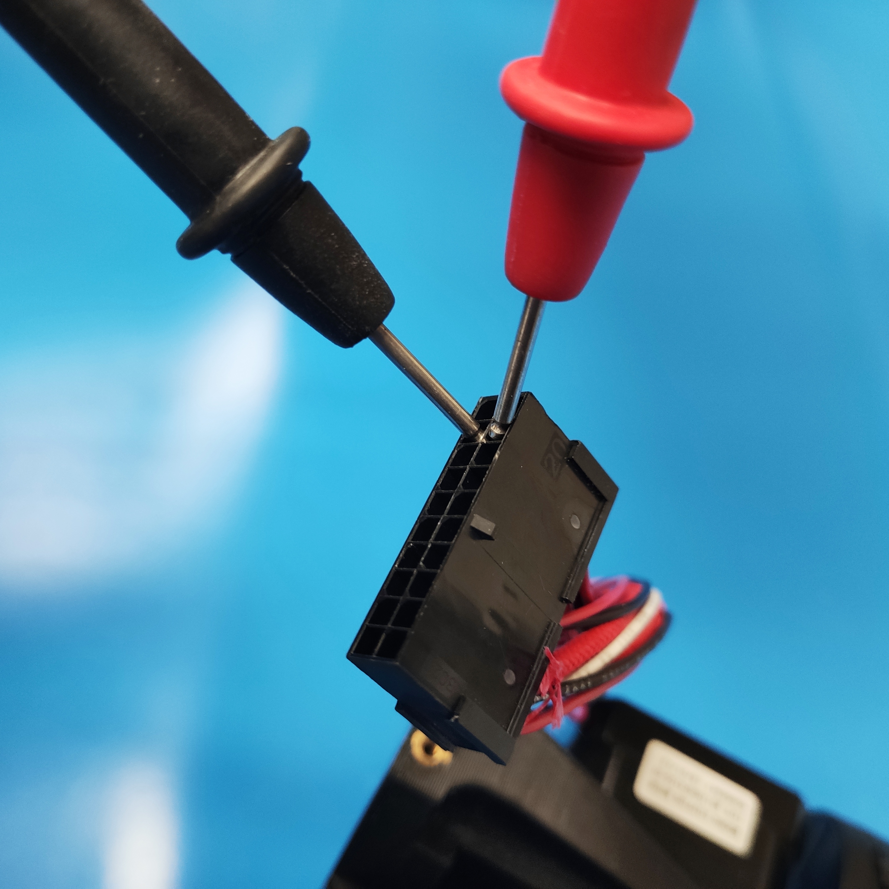
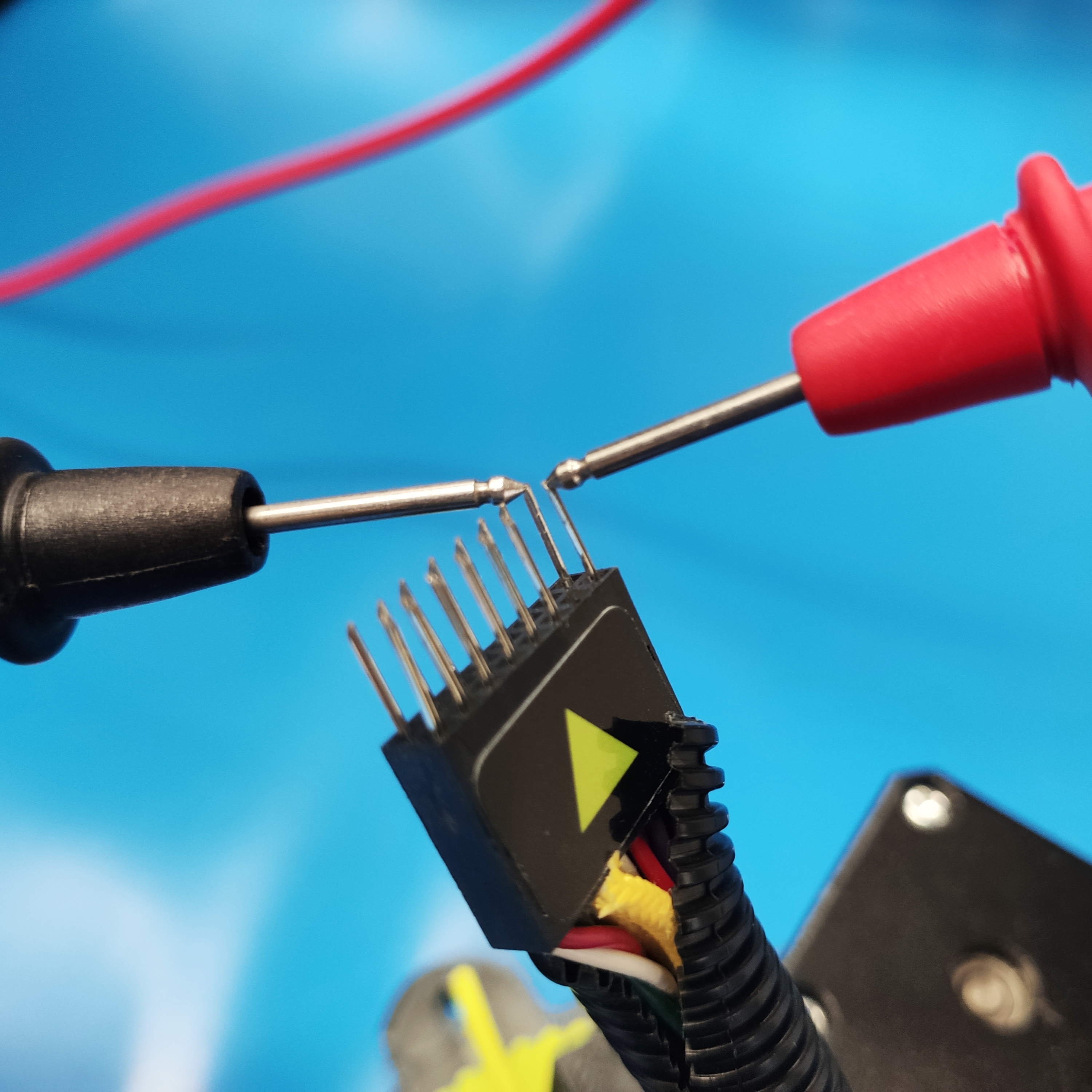
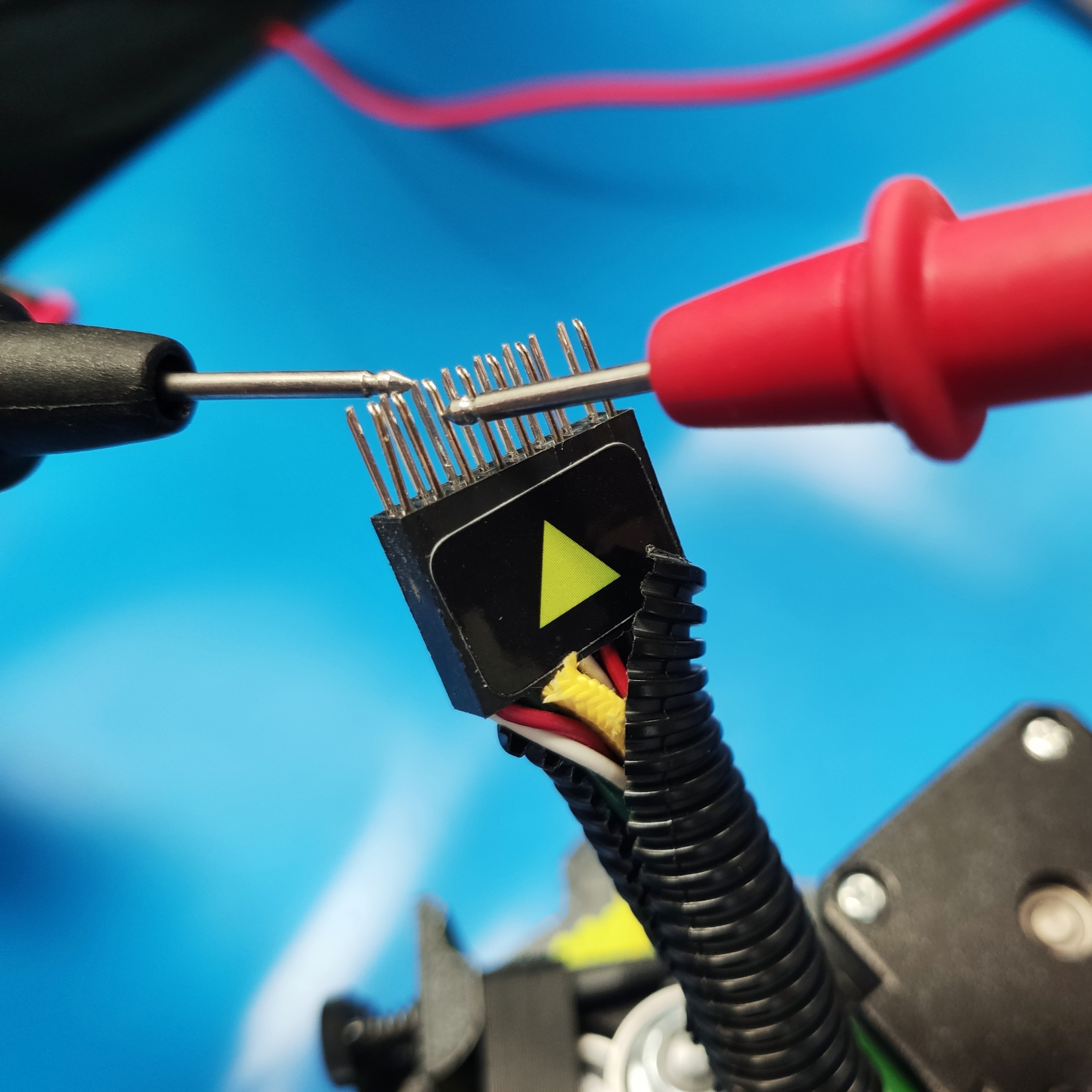
-With the plastic tab/green arrow facing towards you, probe the furthest two wires on the right side of the connector.
-At 25°C (77°F), the thermistor should read ~100k ohms.
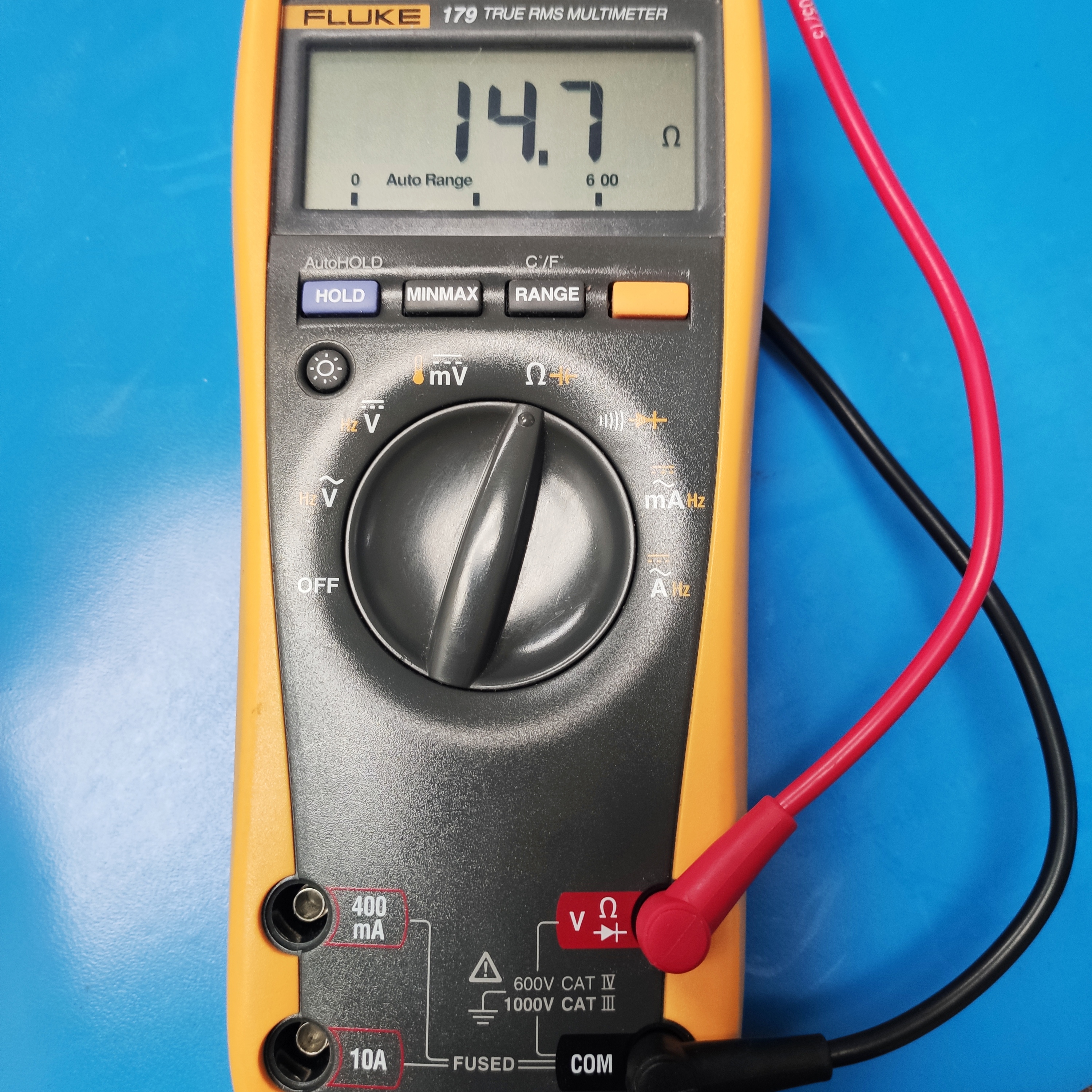
-Set your multimeter to read resistance as indicated by the ohm symbol “Ω”.
-If your multimeter is not auto ranging, set it to read a resistance value of under 100 ohms.
-With the plastic tab/green arrow facing towards you, probe the third set of wires from the left side of the connector.
-These wires are the only braided wires going to the connector.
According to Ohms law (volts²/watts= Ωs) the following resistances for a specific 24v heater cartridge should be as follows:
30w ─ ~19.2 Ωs
40w ─ ~14.4 Ωs
50w ─ ~11.5 Ωs
Note that your resistance may not be exactly these values as there may be some variation in production.
-Connect the tool head to its harness being careful not to push any connectors out of their location.
-If applicable, install the x-carriage cap.
-Plug in the power cord and turn on your 3D printer.
-Thermistors change their resistance based on the ambient temperature surrounding it. If a thermistor is faulty and reading incorrect temperatures, it can cause false temperatures to be displayed for the printer. This may result in the heater cartridge heating beyond safe limits or the printer to error out due to a maximum temperature limit while the heater cartridge is at a low temperature.
-If there is a break in continuity or the thermistor is no longer providing any resistance, your printer will likely show a “mintemp error”.
-Heater cartridges are regulated by the thermistors and if there is too much resistance at the heater cartridge, this will slow down the heating process. If it is taking too long to change the temperature of the heater cartridge, the printer may send the error "Heating failed, printer halted" then shut down the printer as a safety measure.
-If you have further questions or need help understanding your readings, please contact Technical Support by emailing Support@LulzBot.com, or by calling +1-701-809-0800 ext 2.