Open HardwareAssembly Instructions
Guides for installation and assembly of the LulzBot line of products made by FAME 3D LLC.
Guides for installation and assembly of the LulzBot line of products made by FAME 3D LLC.
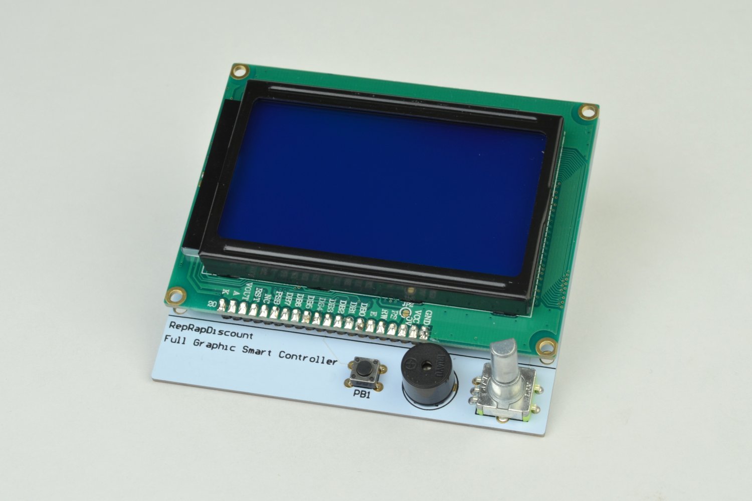
The Graphical LCD Controller (GLCD) is an optional add-on for the LulzBot TAZ 3D printer. This add-on allows for printing without being connected to a computer using its integrated SD card reader. You can also monitor your prints progress and view live information about temperatures, settings and modify some settings on the fly, without having to reflash the firmware.
Tools:
Available from LulzBot.com:
Additional materials needed from other vendors:

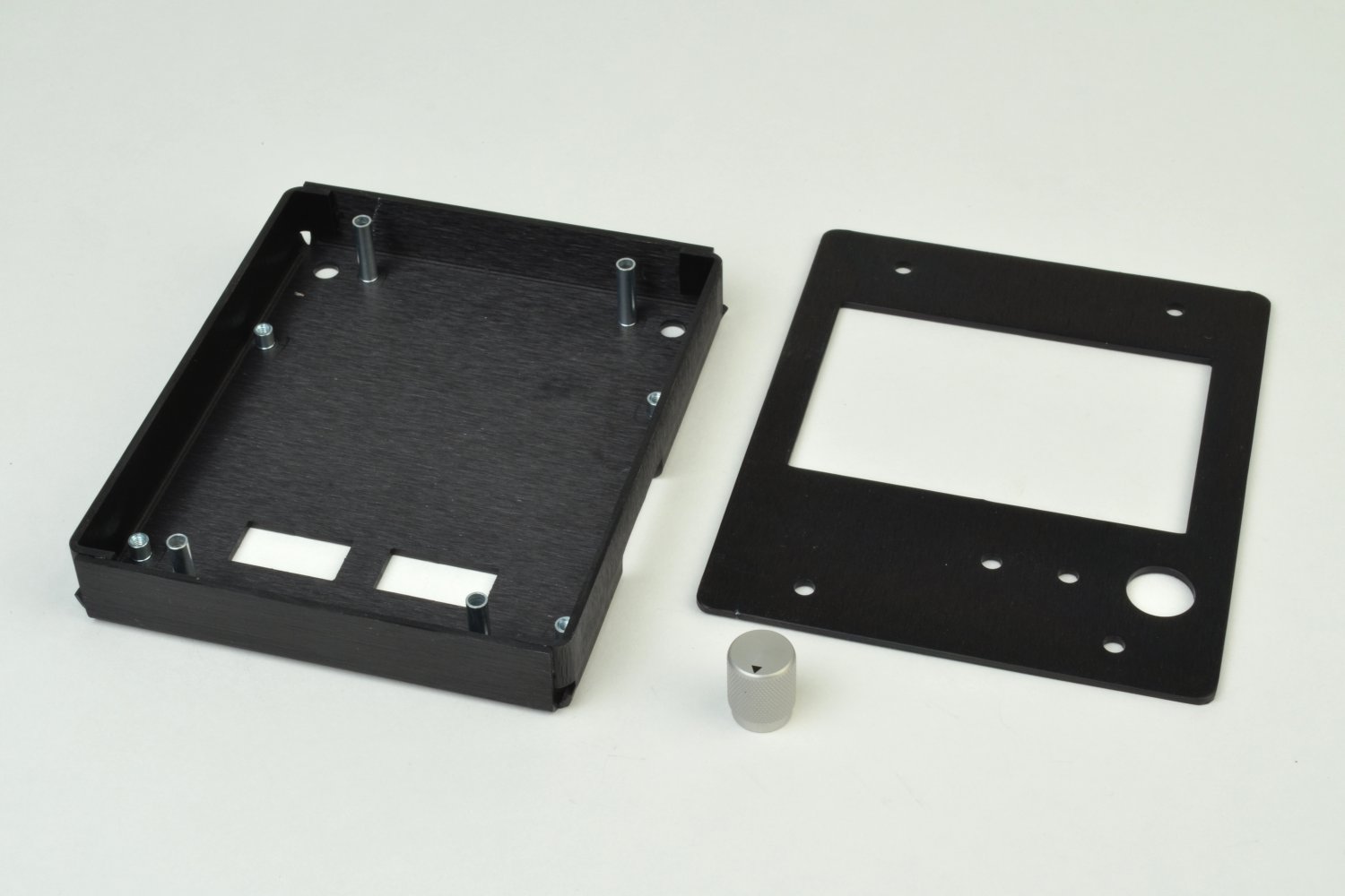
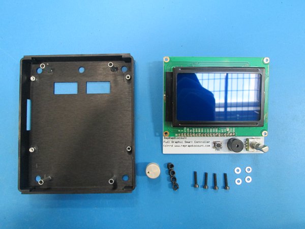
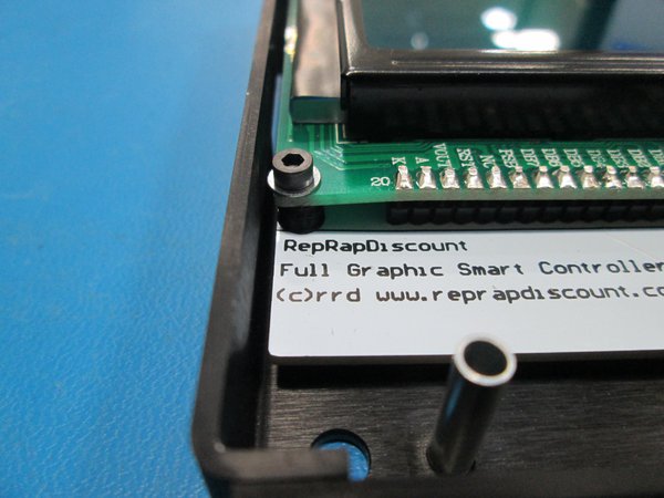
Install optional, printable LCD spacer between the circuit boards and drop a M2.5x12 Socket Head Cap screw with M2.5 washer through it.
Do this in all 4 corners of the board.
Set the LCD with screws down into the LCD case and tighten the screws down. If you decide not to use a spacer in each corner, do not over-tighten.
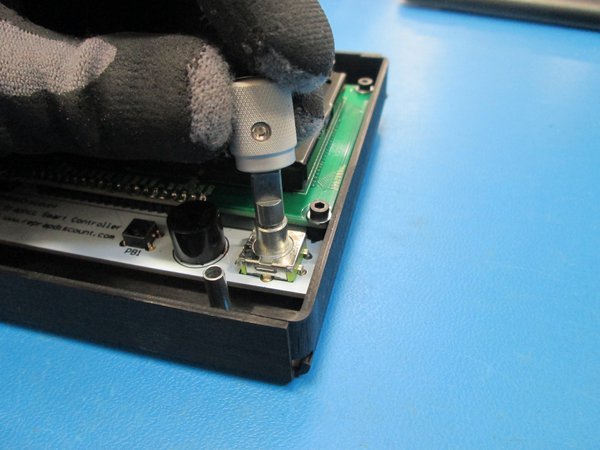
Install the knob onto the LCD with the set screw aligned with the flat.
The knob will go all the way down to a step on the shaft.
Tighten the set screw down using the 1-16 driver.
This next step is best performed with the Y axis assembly removed and with the main frame of the printer laying down.
Keep the two M5 tee-nuts in place on the printer frame and use the existing screws to secure the Graphical LCD controller enclosure onto the printer frame.
Once secured, install the Y axis assembly back into the printer frame.
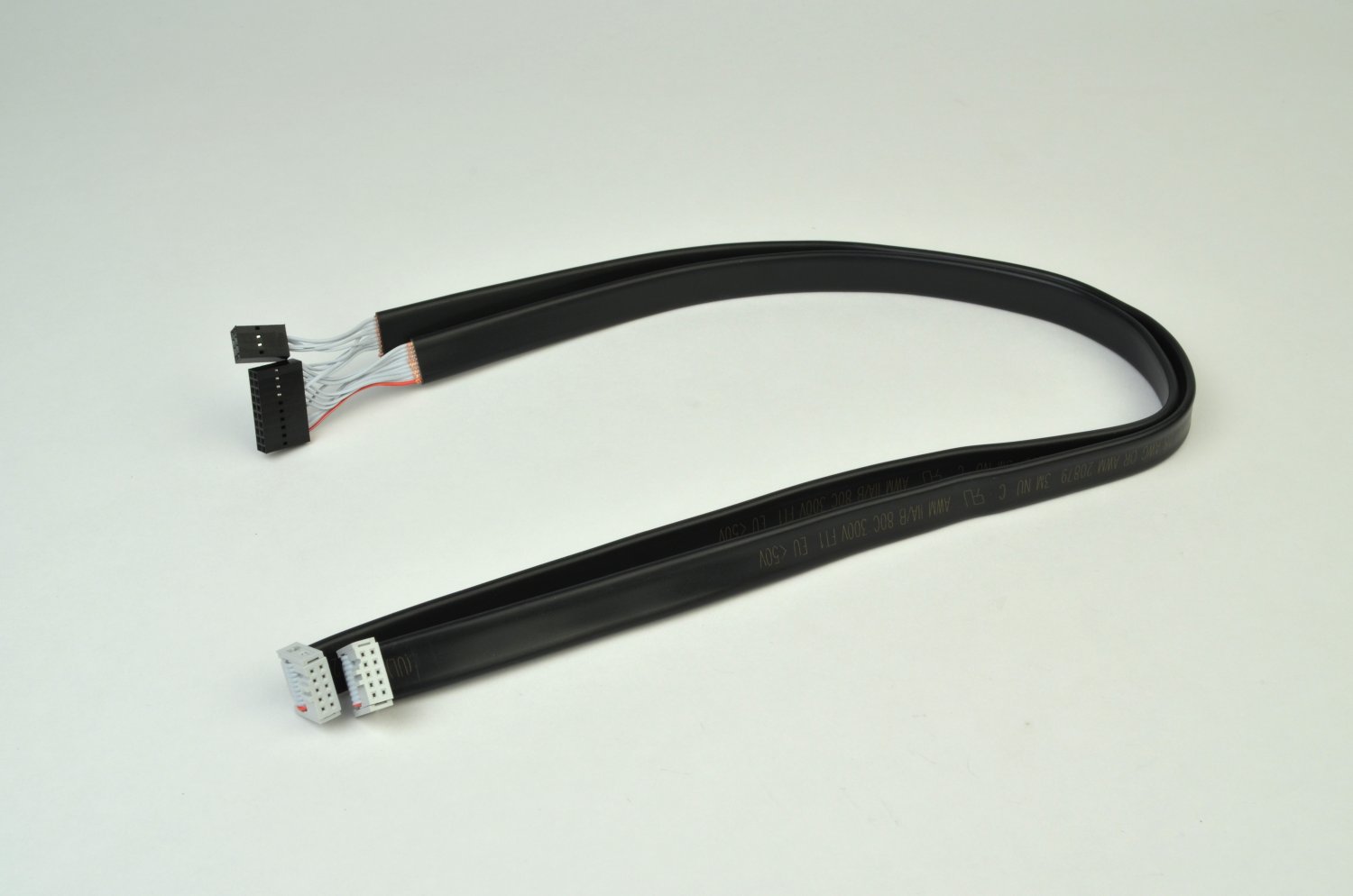
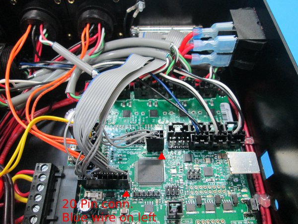
To identify the connectors on the wiring harness, follow the large black connector.
The connector EXP2 has wiring leading to both the large and small connector.
Connect EXP 1 to the left hand connector socket (when looking at the rear of the GLCD enclosure).
The red wire on the large black connector should be oriented so that it's close to the silver USB port.
The smaller connector is plugged into the connection labeled SP1. The connector is marked with a triangle to designate pin 1. SP1 is labeled with a small 1 to indicate orientation.
On each black connector match the black triangle to the Pin one locations noted on the board and in the image below.
Firmware:
Windows:
Mac
Linux
Extract the files to a memorable location.We recommend a new folder on your Desktop, or a new folder in your Home folder.
Extract the Firmware archive. Once extracted, you should have the following folders:
If your firmware archive does not contain ArduinoAddons the file is available HERE.
Open the folder ArduinoAddons and leave the window open.
Windows:
Linux:
Mac:
Windows:
Linux
Mac
In the ArduinoAddons folder from the earlier step, open the Arduino_1_xx folder then select and drag the contents of the libraries folder and any other folders within this directory to the libraries folder from the previous step.
You may be promped to verify the action, if given a choice, select Merge.
If prompted again, select Overwrite or Replace.
Once the copy/transfer finishes, Open the Arduino IDE.
If you have having difficulties, a Windows modification guide can be found here
Open the Arduino IDE.
Select File > Open .
Navigate to the folder containing the Marlin folder you previously extracted.
Open the file titled Marlin.ino or Marlin.
Once opened, you should see multiple tabs across the top of the Arduino IDE window.
Locate and select the tab titled: Configuration.h
In the menu, select Edit > Find.
Search for the following text:
DEFAULT_AXIS_STEPS_PER_UNIT
This figure can be found in your paperwork, on the Test Acceptance Record labeled: E0.
In the Arduino IDE, on the Configuration.h tab, update the information found in:
DEFAULT_AXIS_STEPS_PER_UNIT
You will need to update the last 800 number with the Estep value found earlier. If you do not have the Esteps information you will need to update the last 800 number with a temporary Estep value of 840. You will need to perform extruder calibration after verifying printer operations. A guide on doing so can be found here.
Once changed save the modifications by pressing CTRL & S or by selecting in the menu File > Save.
Power on the printer and connect the TAZ to your computer with the supplied USB cable.
Once connected, in the Arduino IDE menu, select:
Upload the firmware to the TAZ 3D printer by selecting File > Upload Sketch or by pressing Ctrl & U.
The firmware will now compile, then will upload to the board. Once finished, the Arduino IDE will display a completion message.
Disconnect the TAZ from your computer.
Install the electronics enclosure lid using the 4 M3 screws.
Enjoy using your new Graphical LCD Controller!