Open HardwareAssembly Instructions
Guides for installation and assembly of the LulzBot line of products made by FAME 3D LLC.
Guides for installation and assembly of the LulzBot line of products made by FAME 3D LLC.
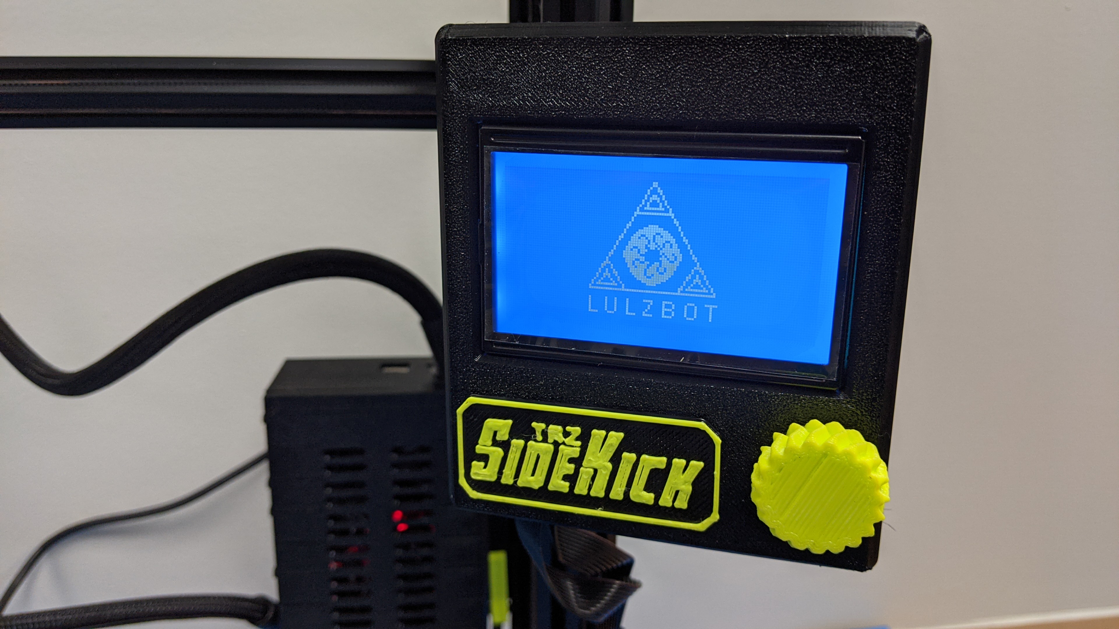
With the LulzBot TAZ SideKick Graphical LCD Controller, your creativity is free from any direct ties with USB cables or computers. Follow the steps below to untether your LulzBot TAZ SideKick Printer.
The items required for the installation of the TAZ SideKick Graphical LCD:
•SideKick Graphical LCD kit
•2x M4x5mm BCHC
•2mm hex wrench
•2.5mm hex wrench
•3mm hex wrench

Before starting, power off and unplug your TAZ SideKick.
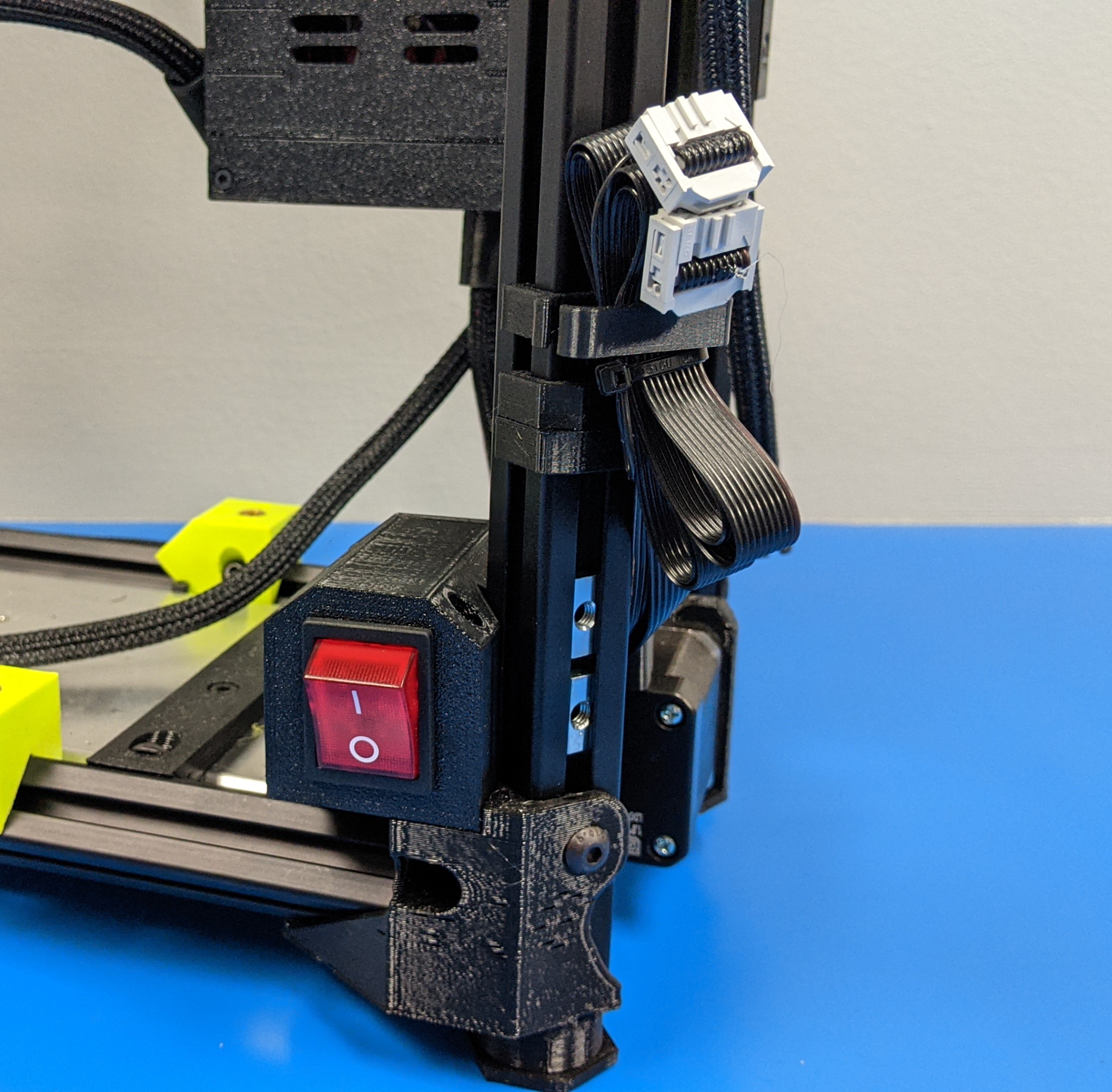
2A.
Remove the LCD cable harnesses from the 3d printed holder.
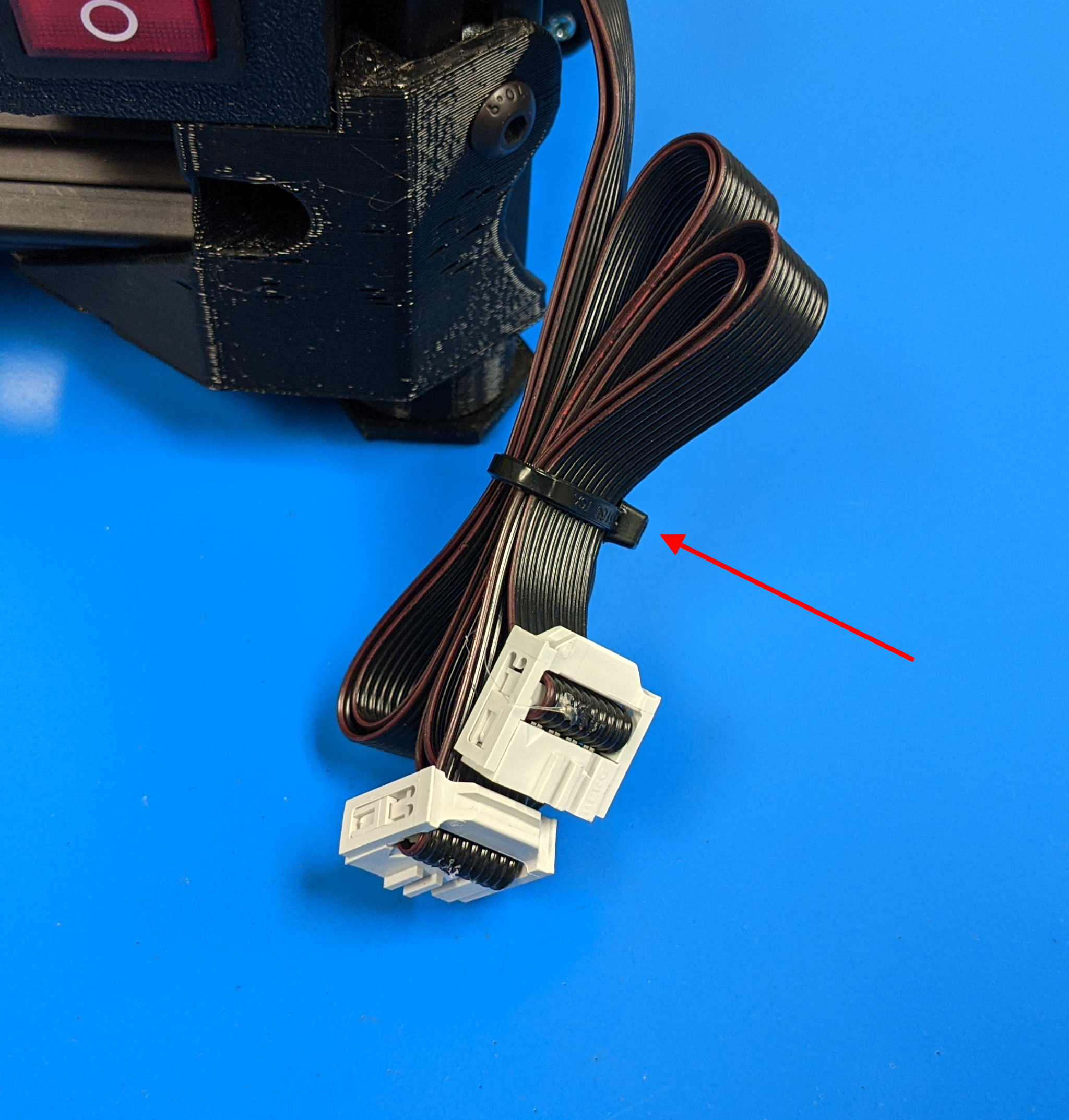
2B.
Cut the zip tie holding the harness together.
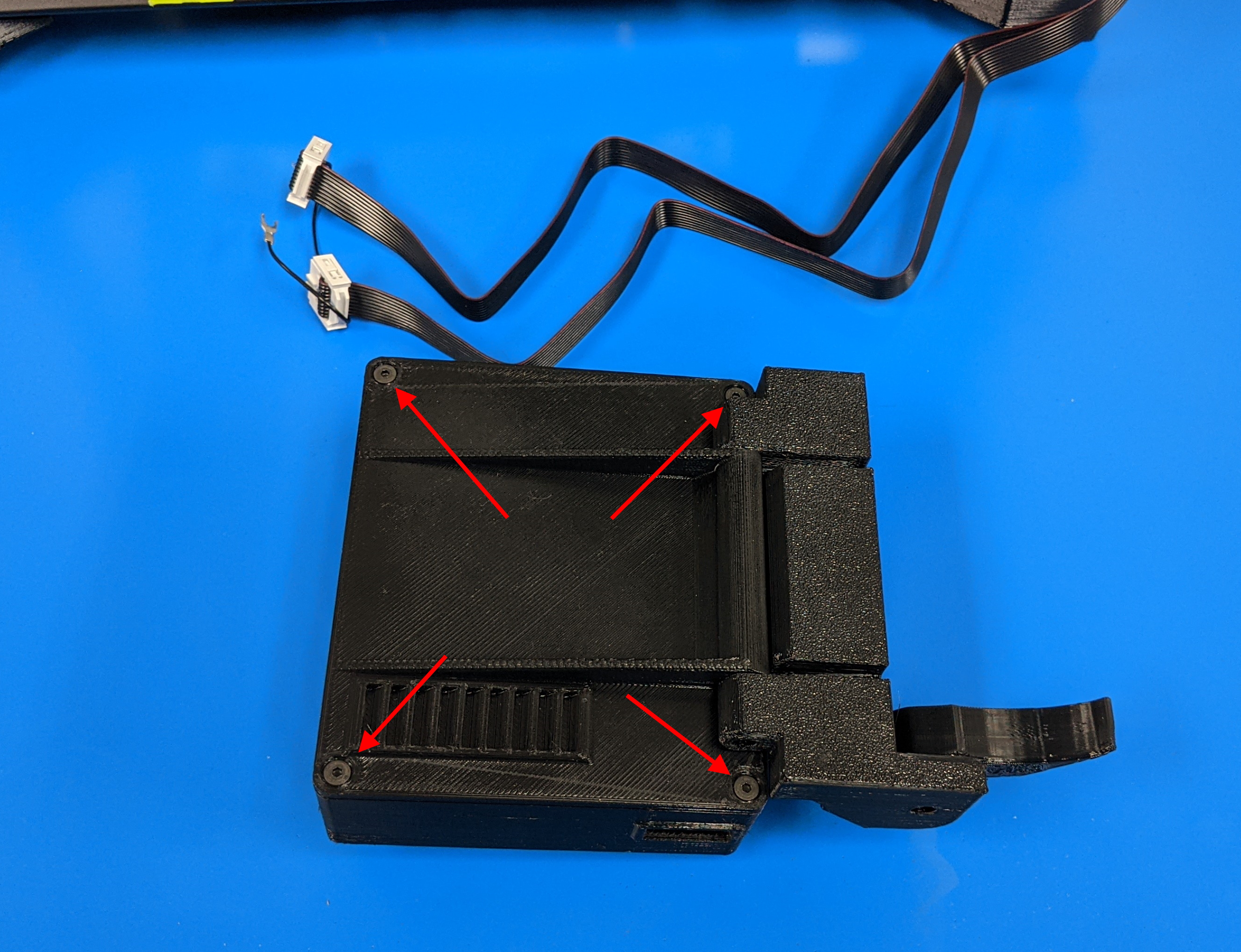
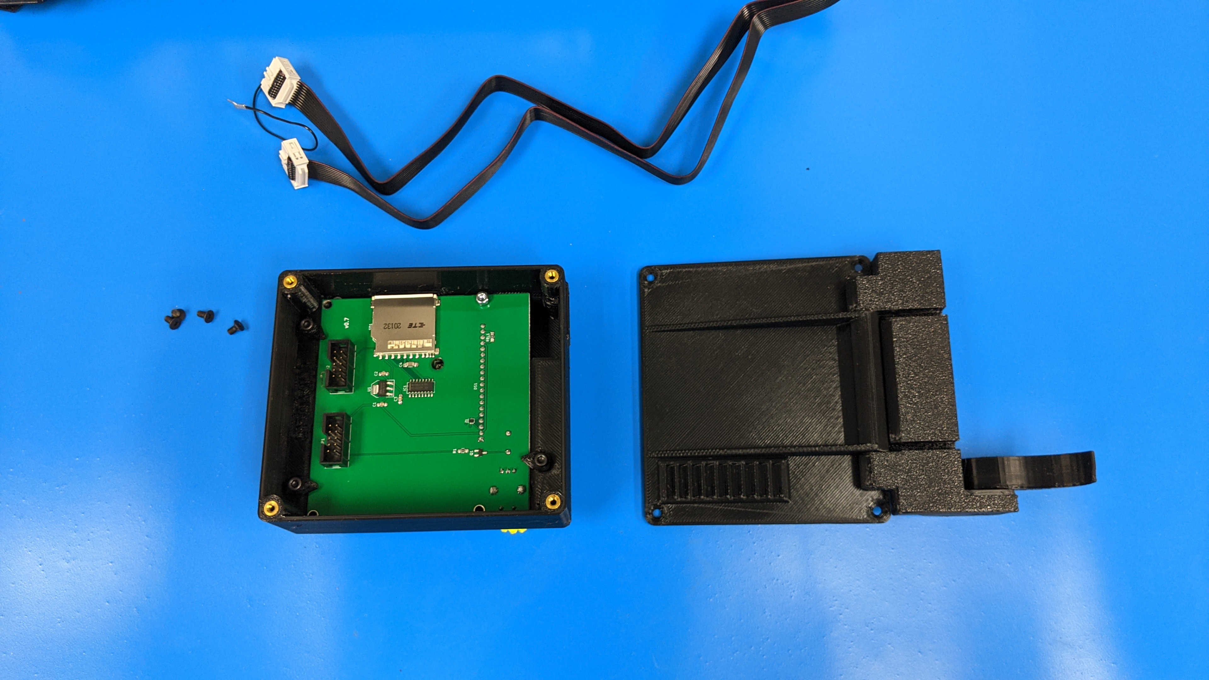
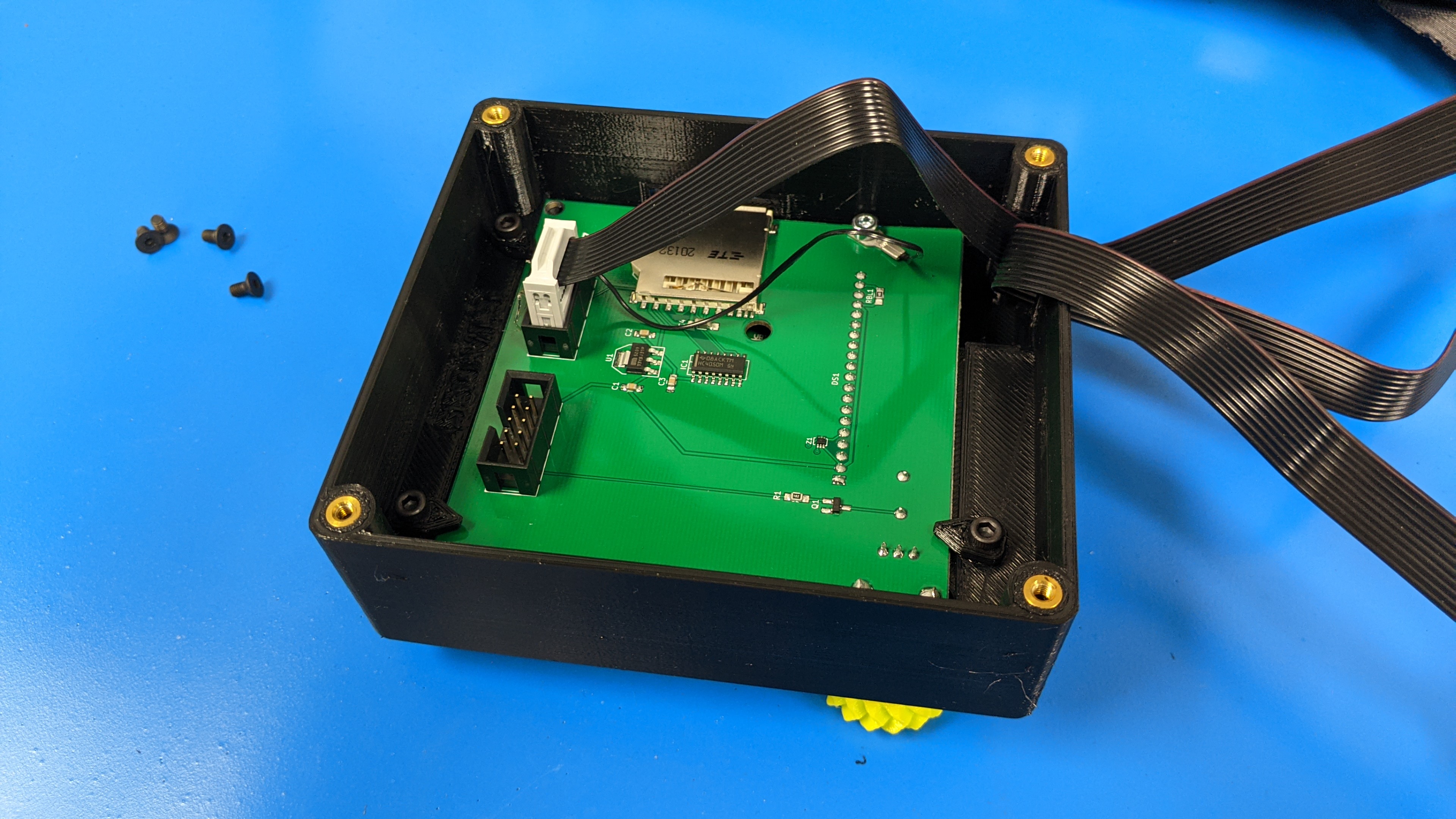
Remove the 4x m2 screws that hold the rear cover of the gLCD in place.
Set back panel and screws aside.
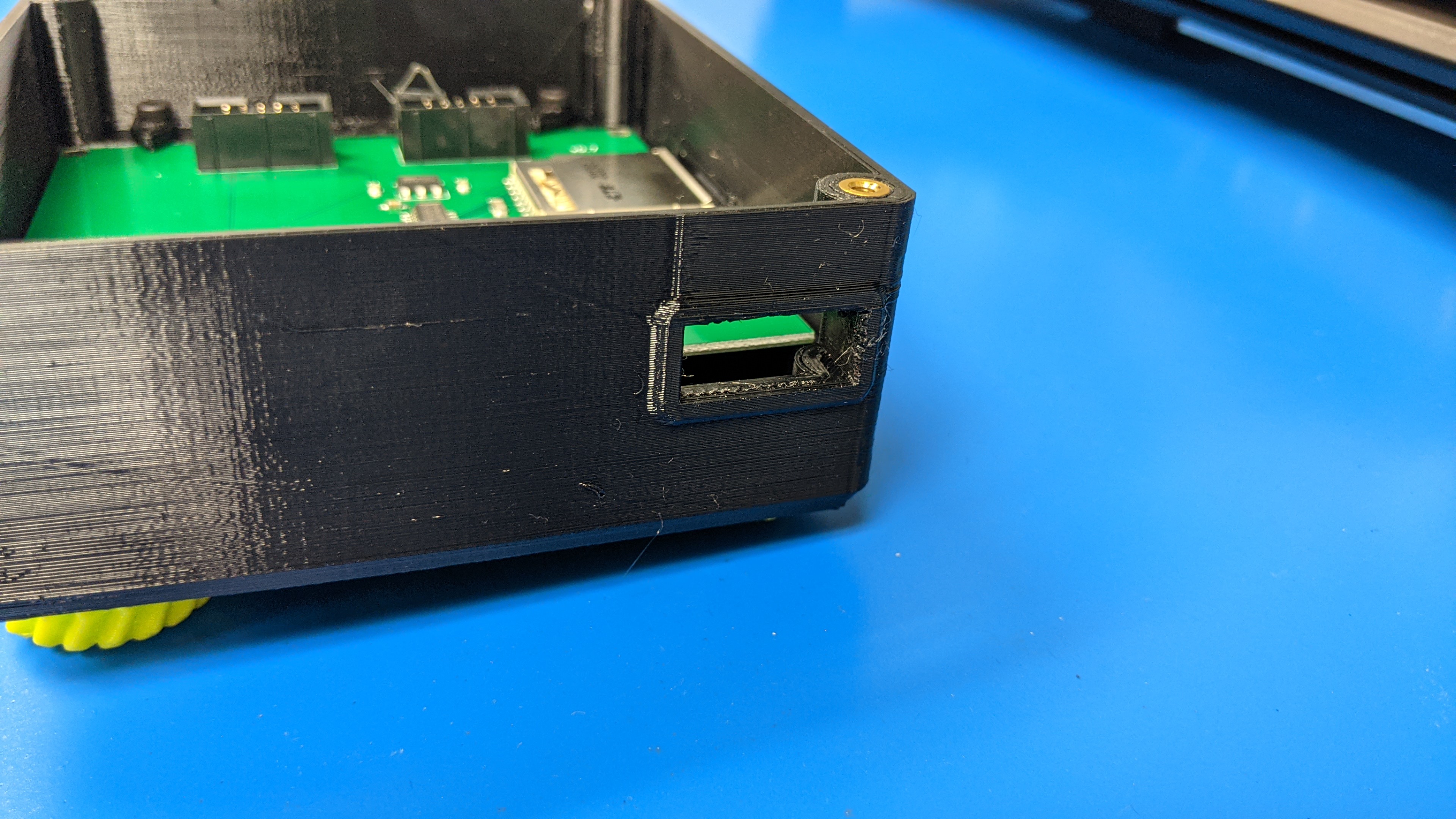
4A.
Locate opening at the bottom of the gLCD case and insert each ribbon cable one at a time.
4B.
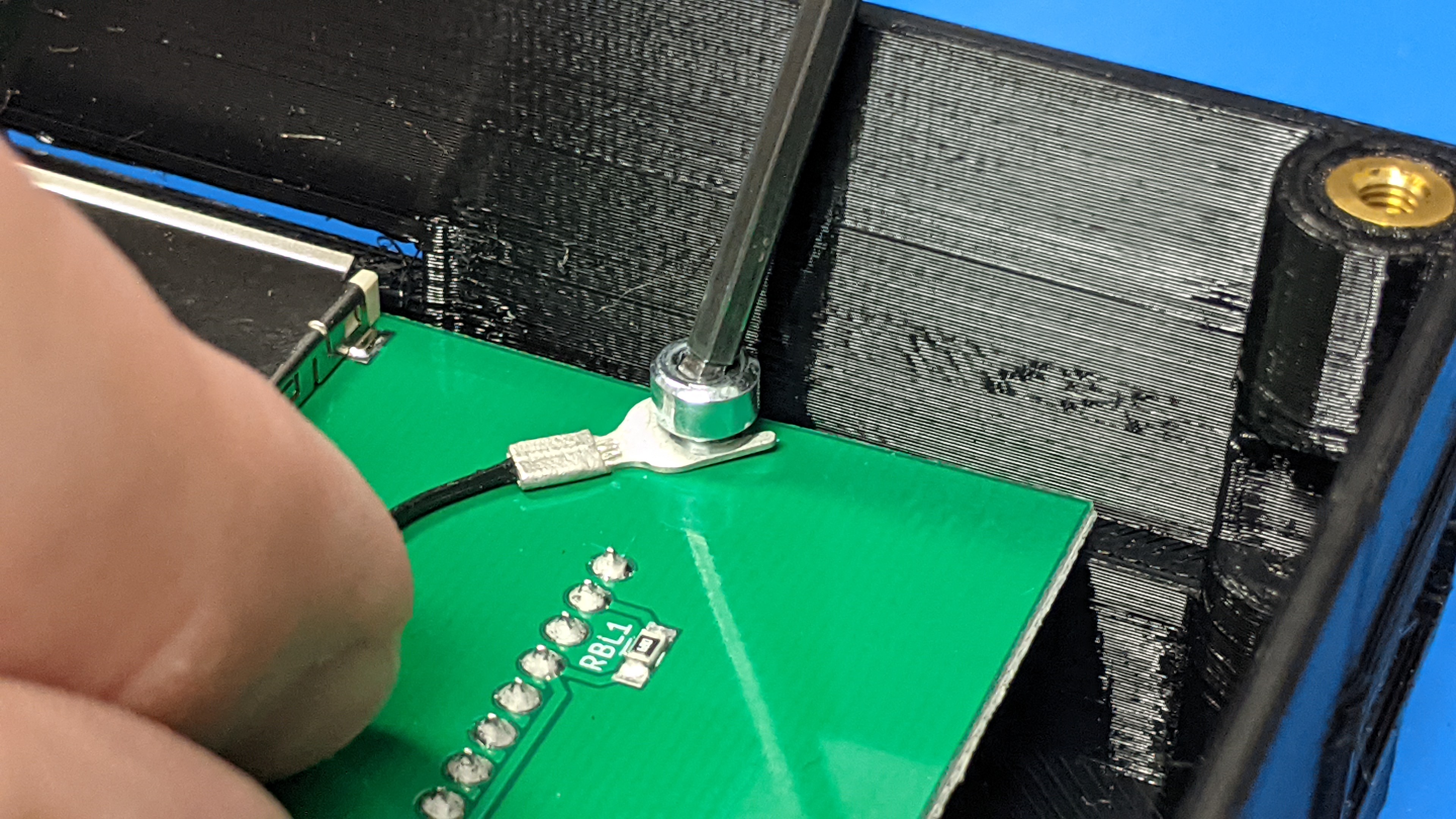
Use 2.5mm hex wrench and loosen ground wire screw.
Do not fully remove.
4C.
Slide forked connector under the screw.
4D.
Tighten gorund connector until finger tight.
Do not over tighten.
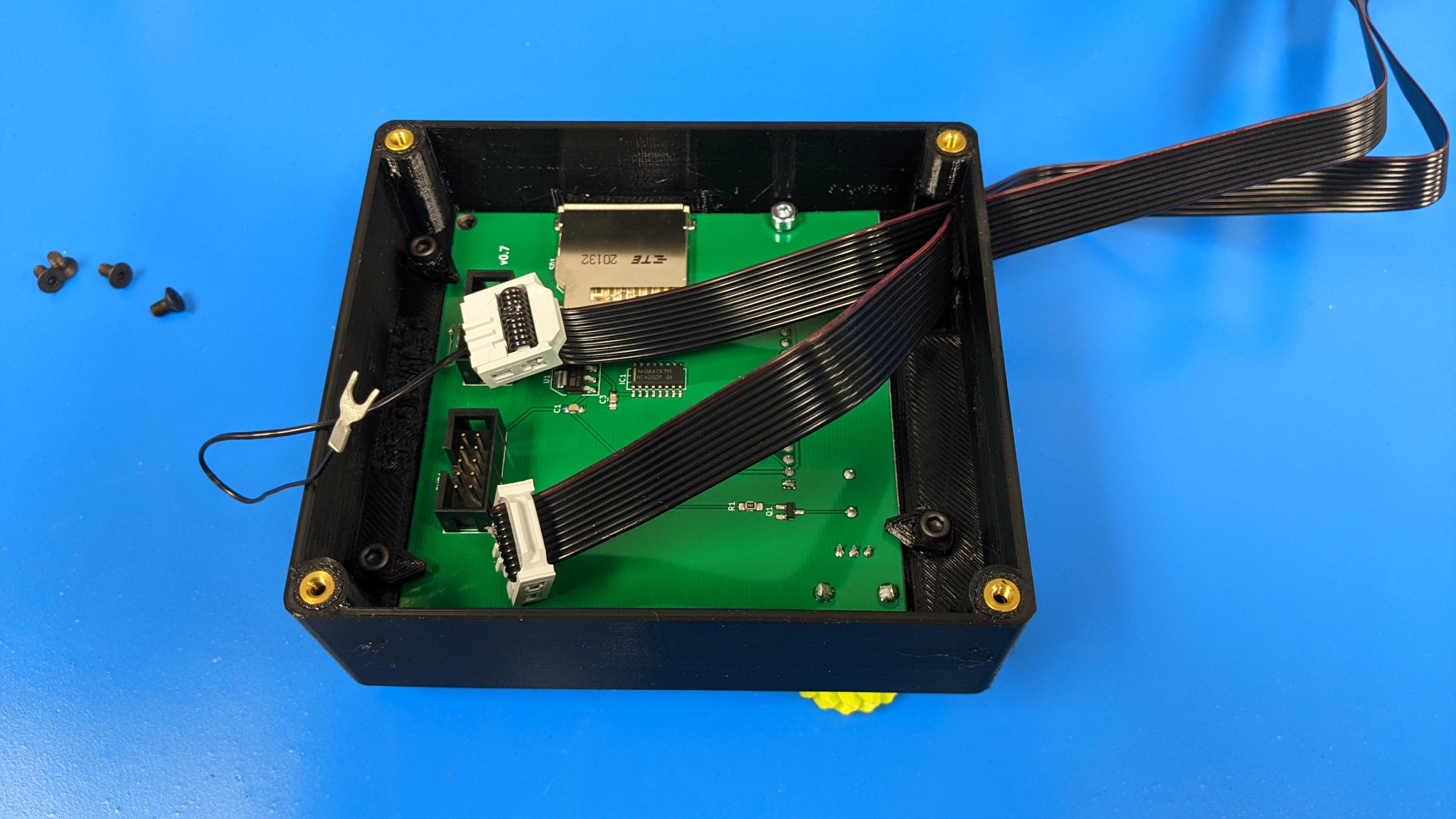
5A.
Plug ribbon cable with the ground wire in it into the right side of the gLCD. (Side closest to the SD card slot)
5B.
Plug remaining ribbon cable into left side of the gLCD
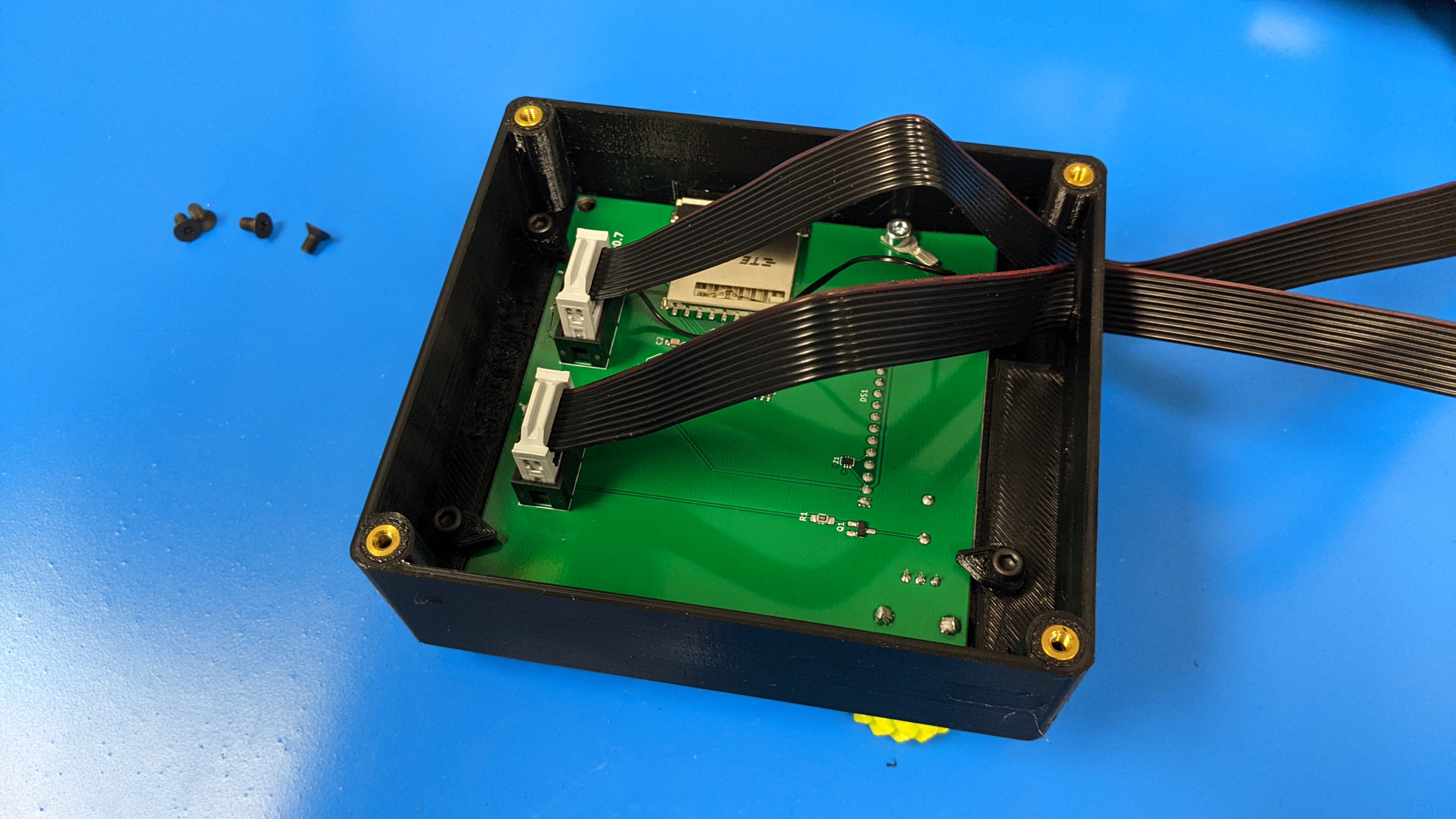
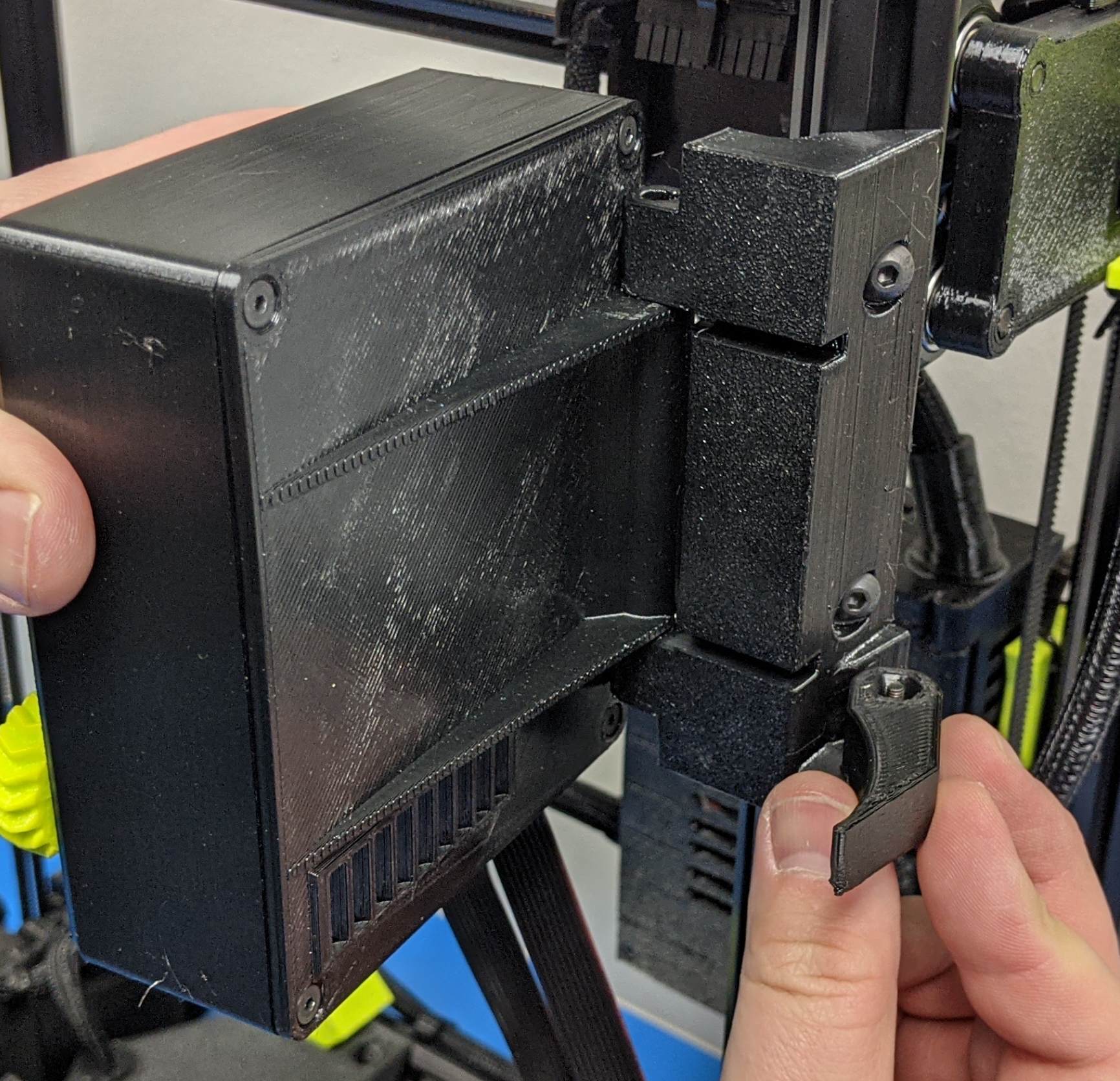
Use your 2mm hex wrench to install the 4x m3 screws into the back of the gLCD
Ensure that the orientation is correct with the mounting side is at the same side as the SD card slot.
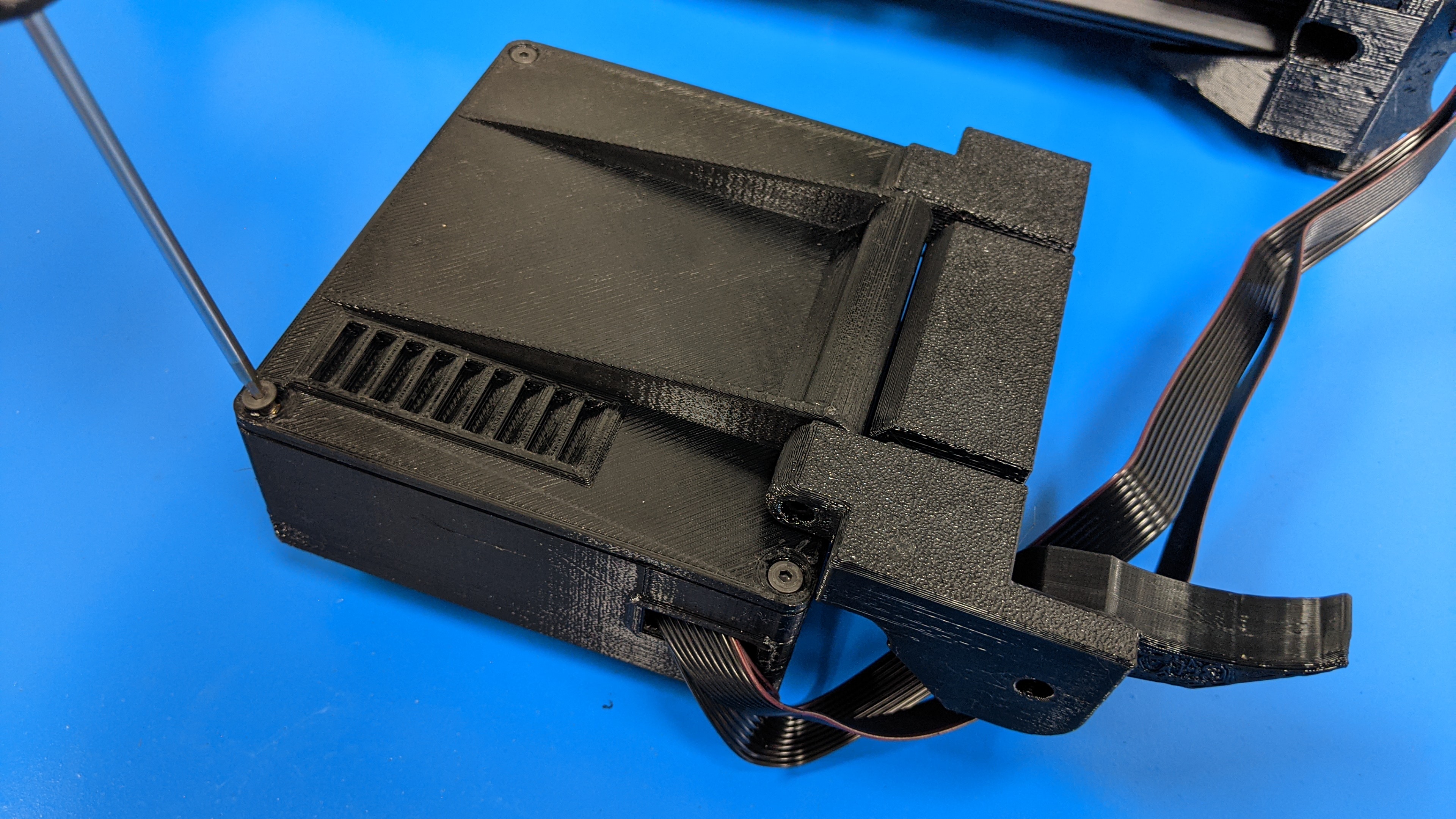
7A.
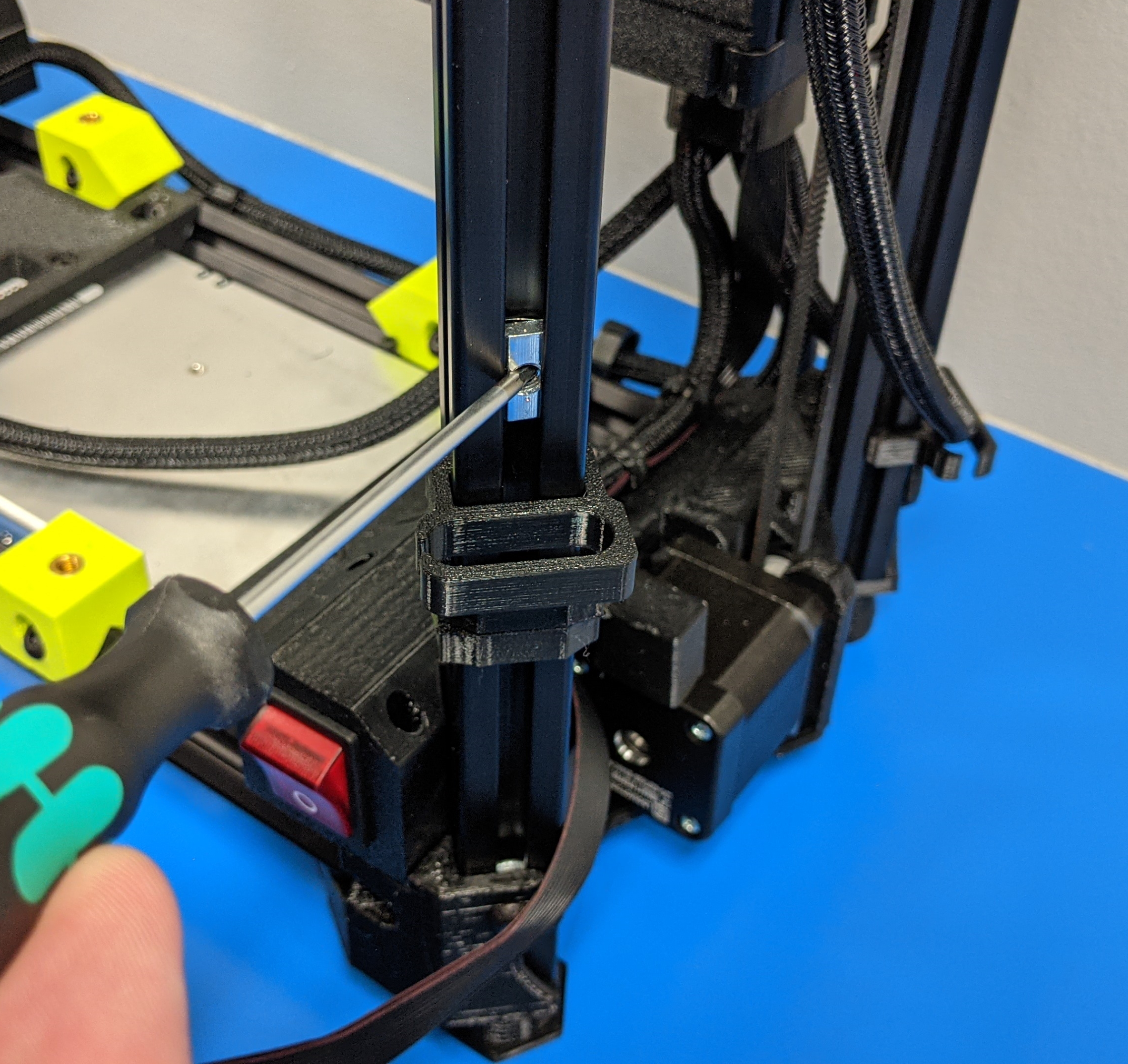
Move the two pre-installed t-nuts up from the bottom of the printer closer to the top of the printer frame.
7B.
Try to align the t-nuts with the openings on the gLCD.
7C.
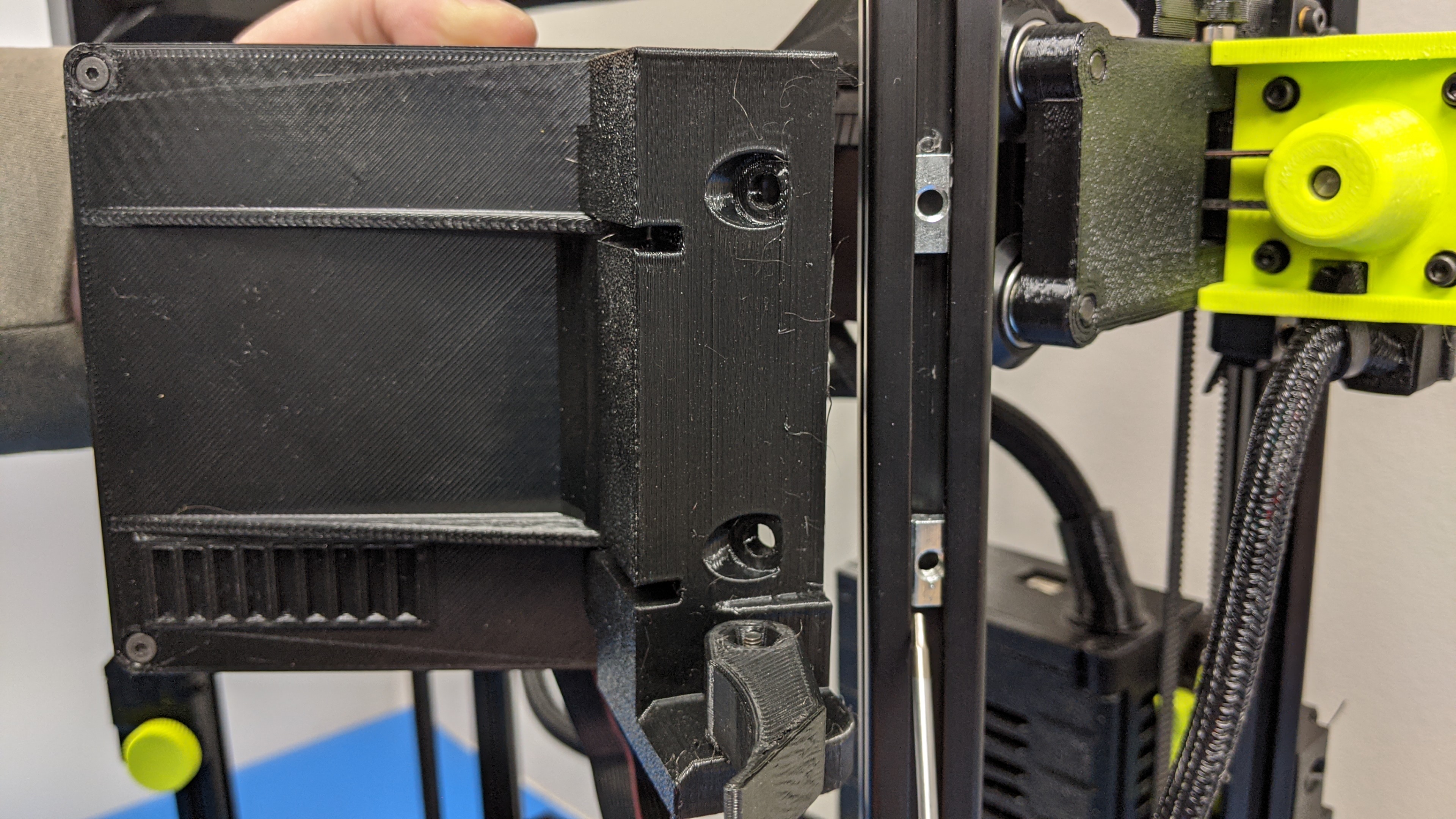
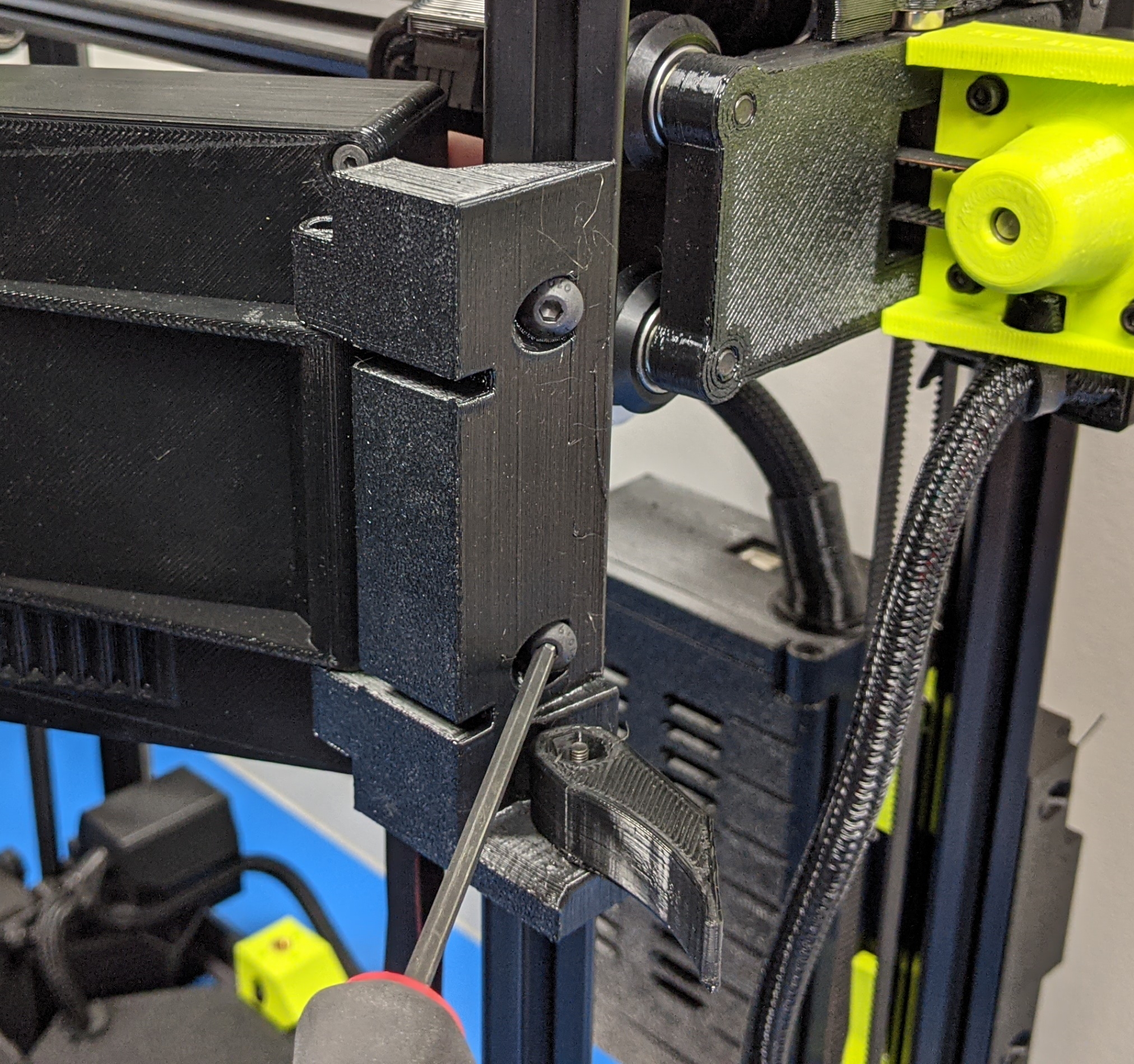
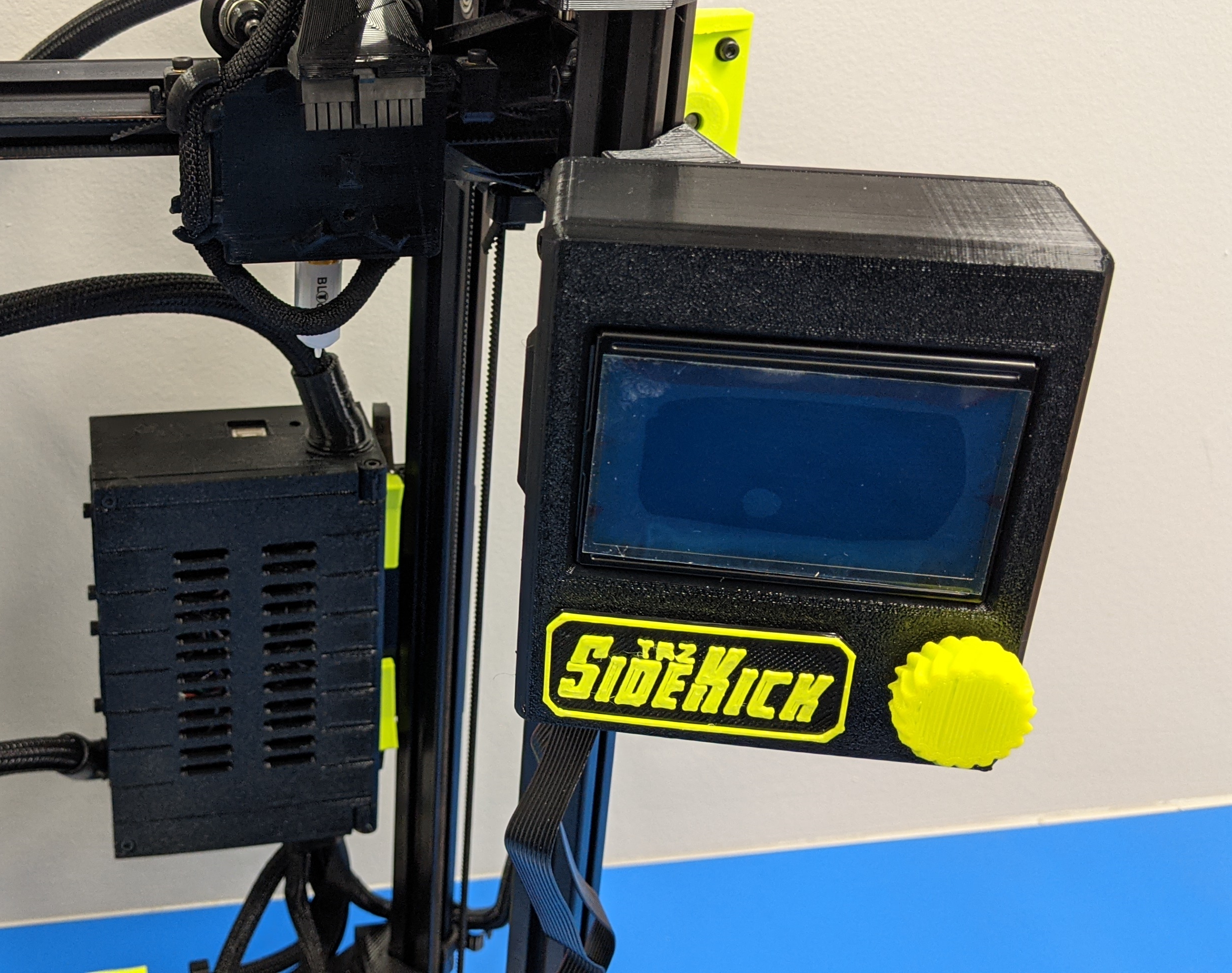
Use one of the m4x5mm screws to mount the top of the gLCD to the printer.
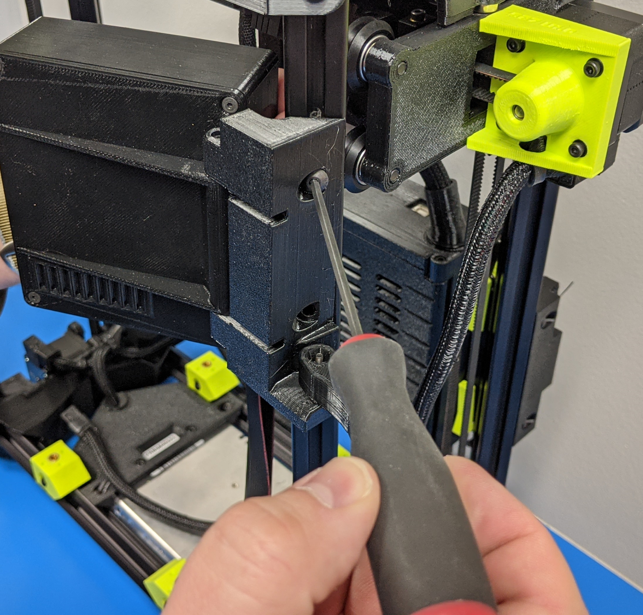
7D.
Use the last m4x5mm screw to mount the bottom of the gLCD to the printer.
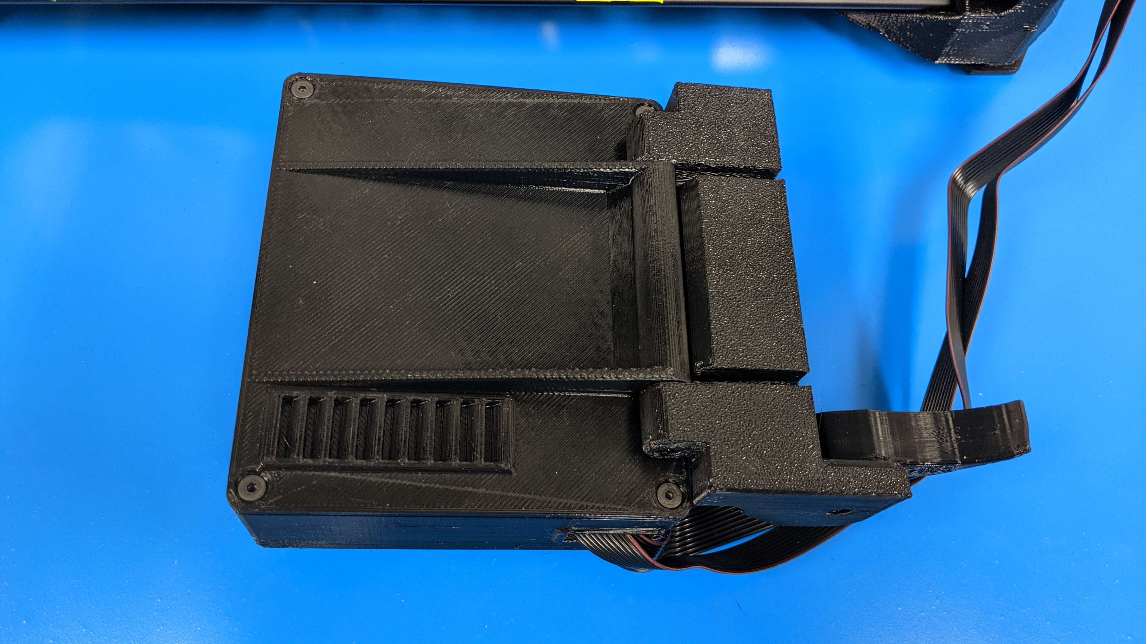
7E.
Turn LCD around and position with positioning arm.
8A.
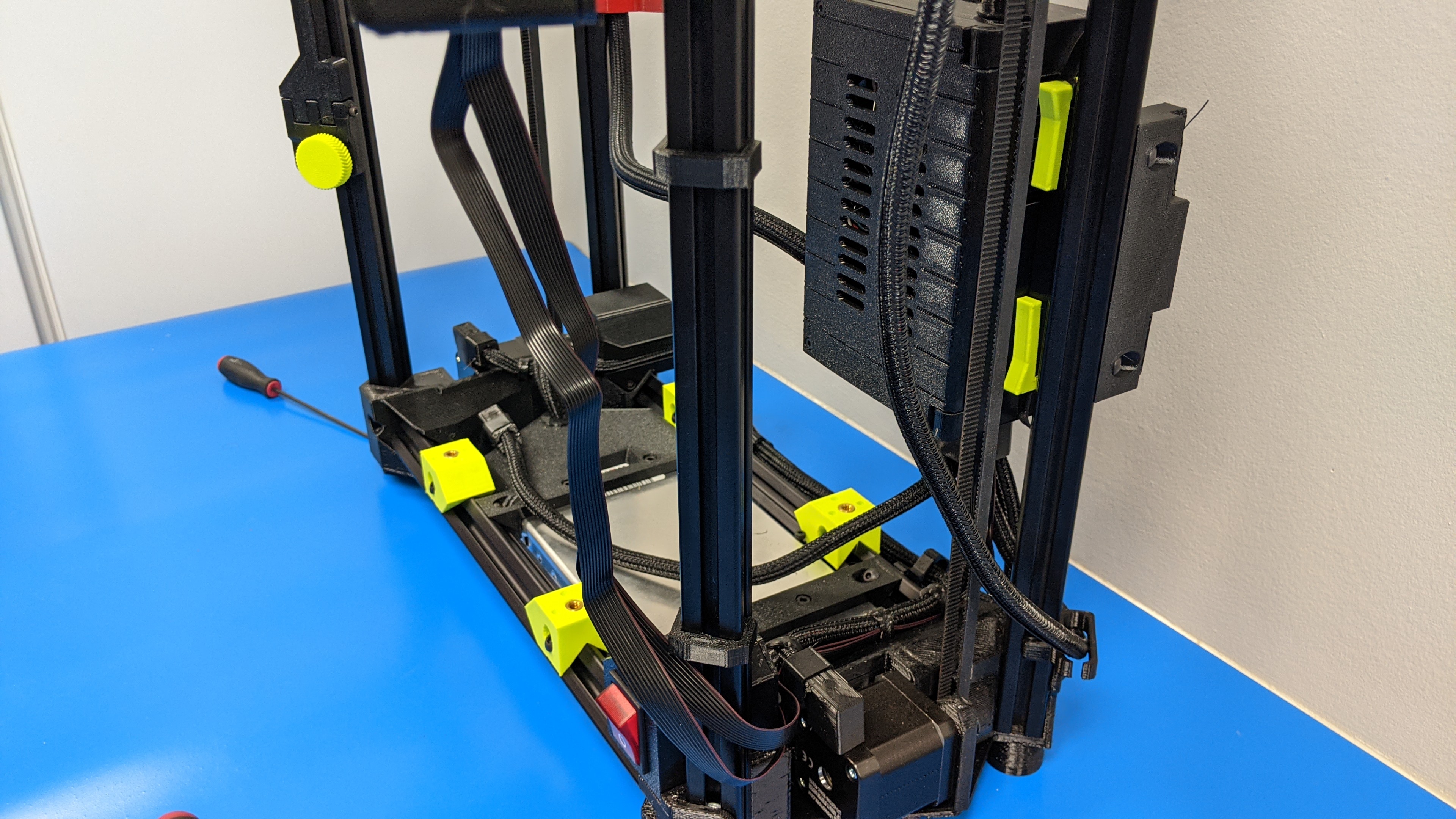
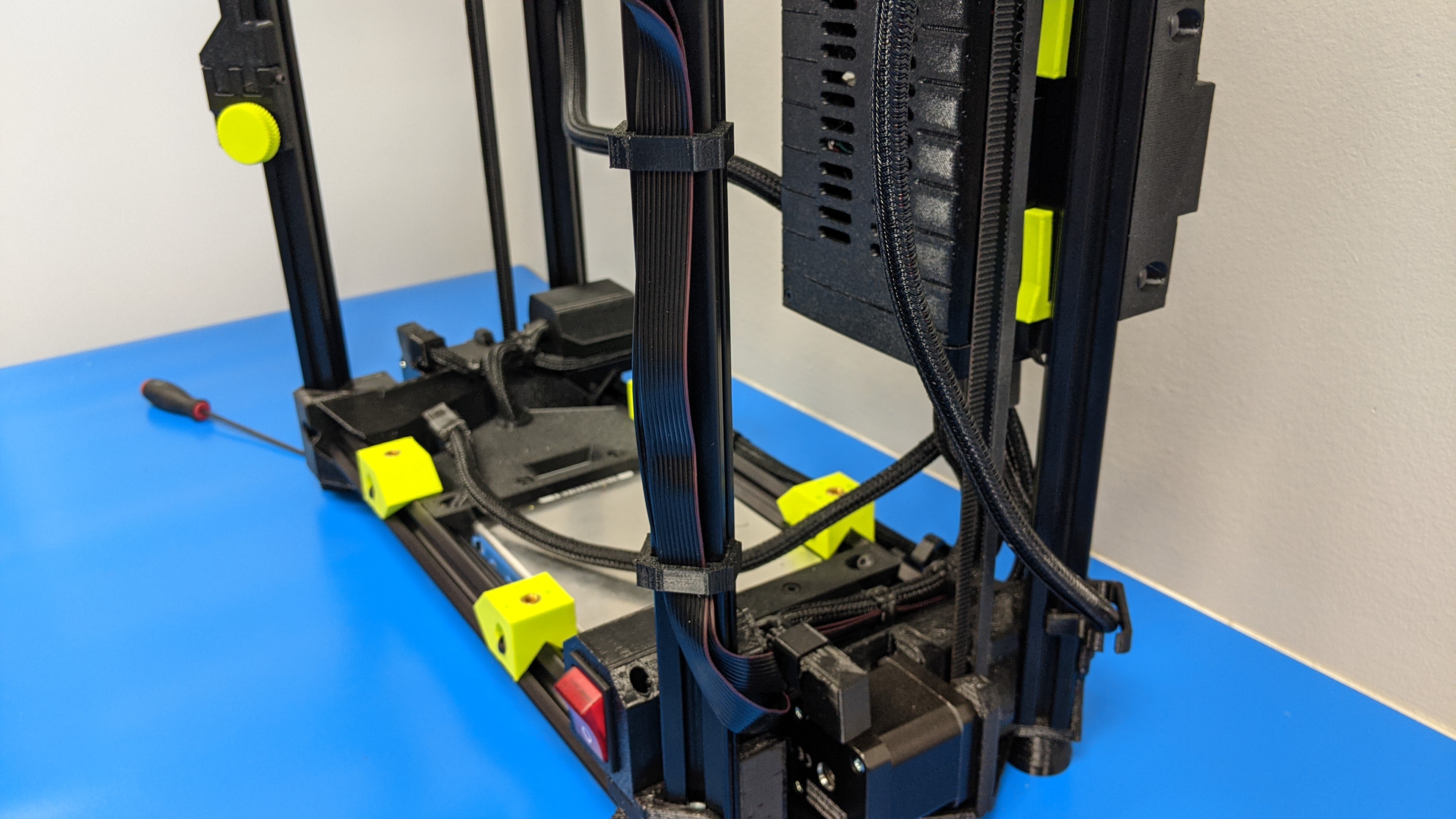
Move the 3d printed ribbon cable mounts up to evenly distribute your gLCD ribbon cables.
8B.
Place the ribbon cables together and slide into the bottom cable mount.
8C.
Repeat previous step for the top mount as well.
Note that you want to insert the ribbon cables from the left. If your mount is open on the right, you will want to remove the mount and flip it around.

Power on your printer to test gLCD!