Open HardwareAssembly Instructions
Guides for installation and assembly of the LulzBot line of products made by FAME 3D LLC.
Guides for installation and assembly of the LulzBot line of products made by FAME 3D LLC.
Take a printer from the rack at the end of the assembly line and place it on the calibration table. Grab a Y axis assembly that matches the size and color of the printer and place it on the table next to printer.
Make sure you have the following items required for calibration:
Follow the pre-calibration checklist to verify all the parts are installed correctly.
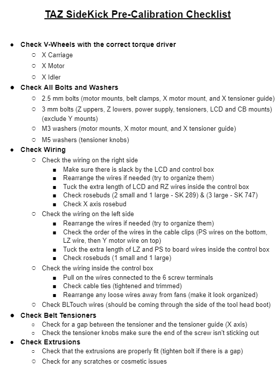
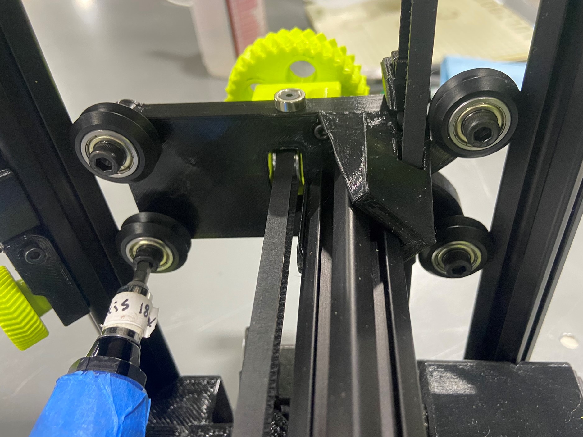
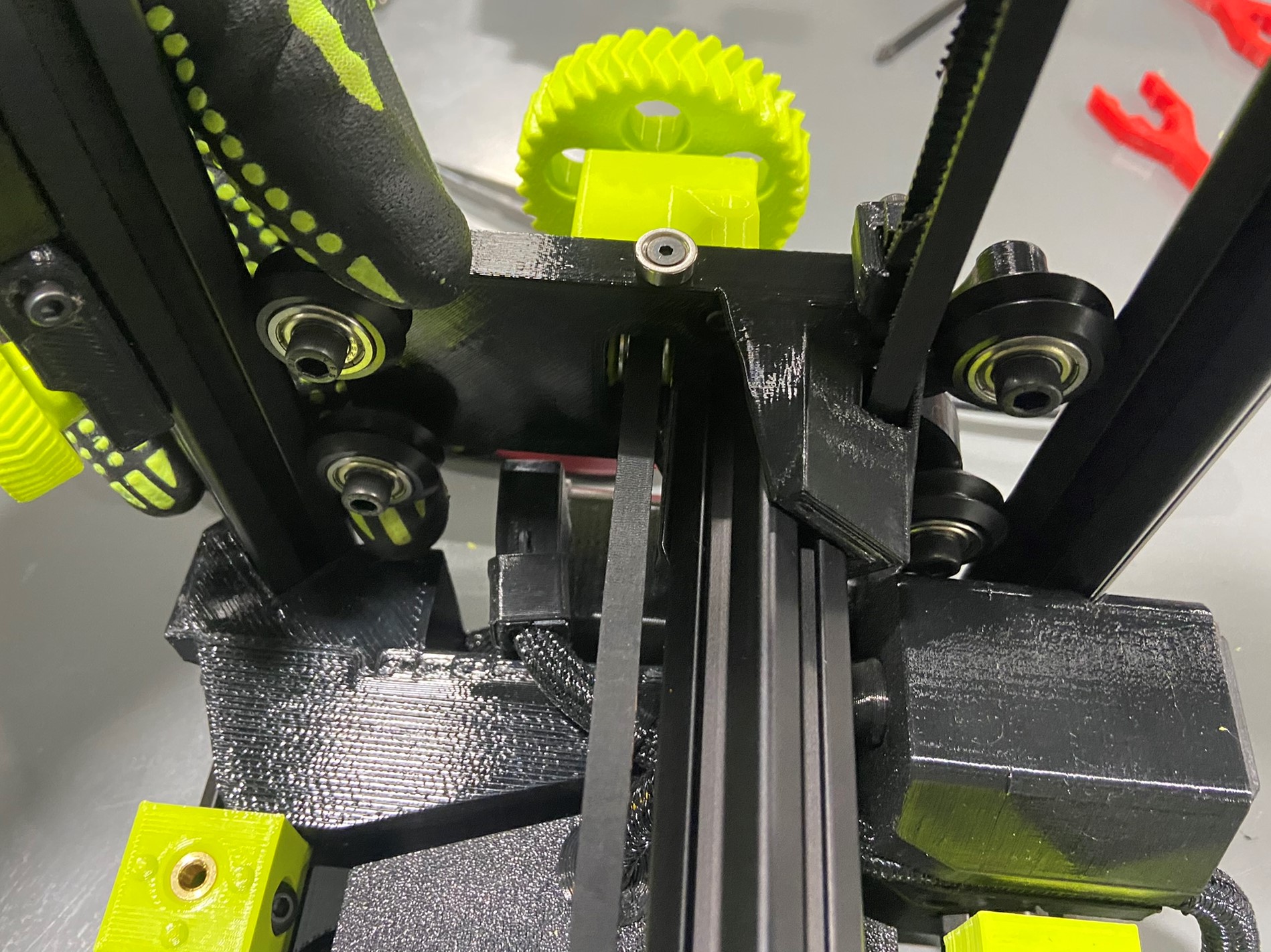
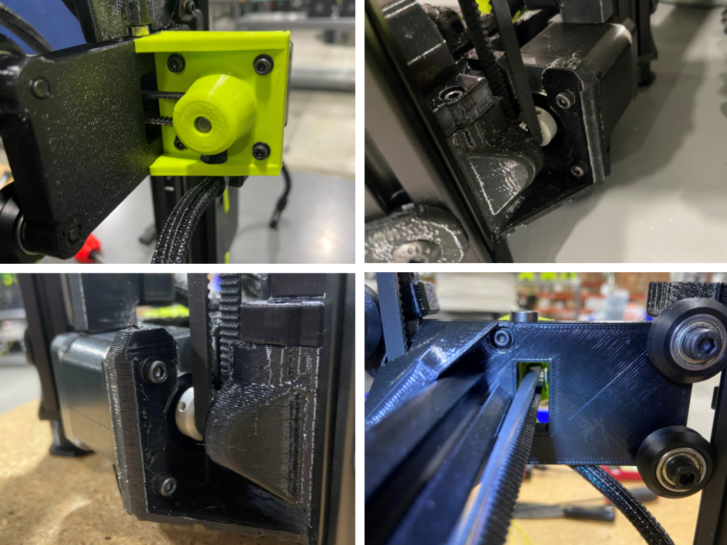
First we will check the torque of each V-wheel:
Note: If any V-wheel fails the torque check make a note of what V-wheel failed and continue checking the printer.
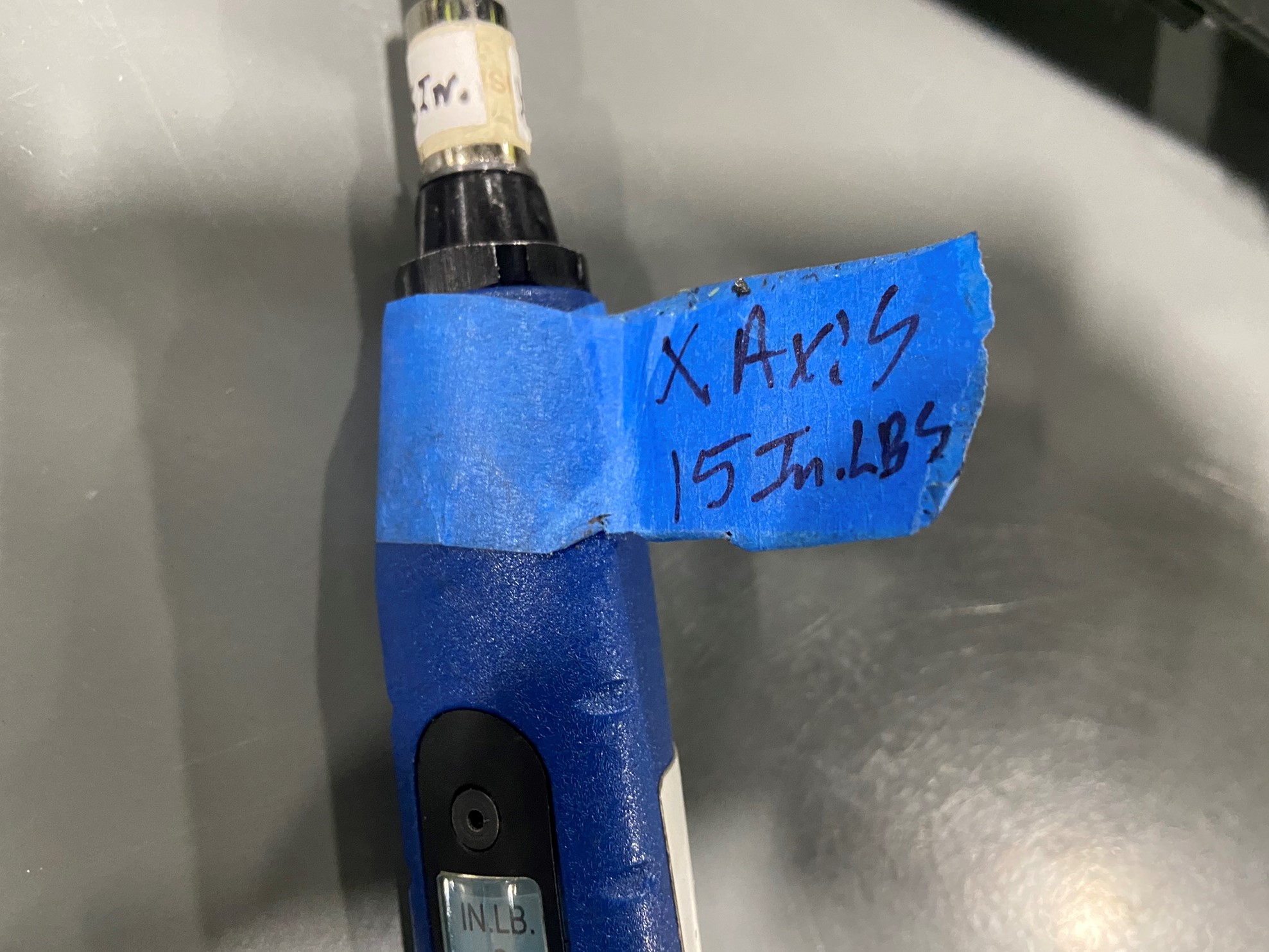
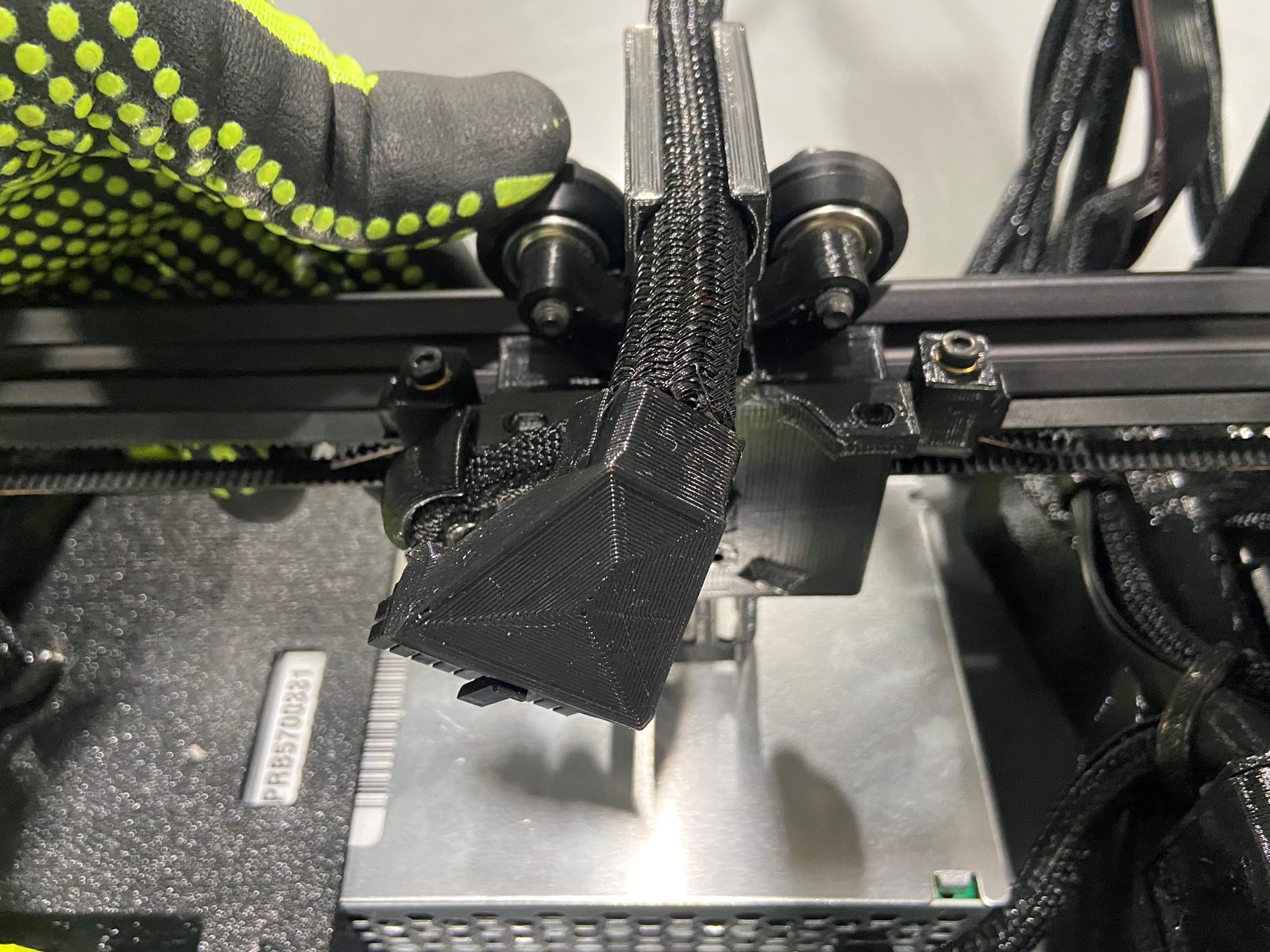
Using the X axis torque driver (set at 15 in*lbs) test each V-wheel on the X carriage. Then using your finger try to spin each wheel without moving the carriage, if any wheel spins while the carriage stays in place make note of that wheel.
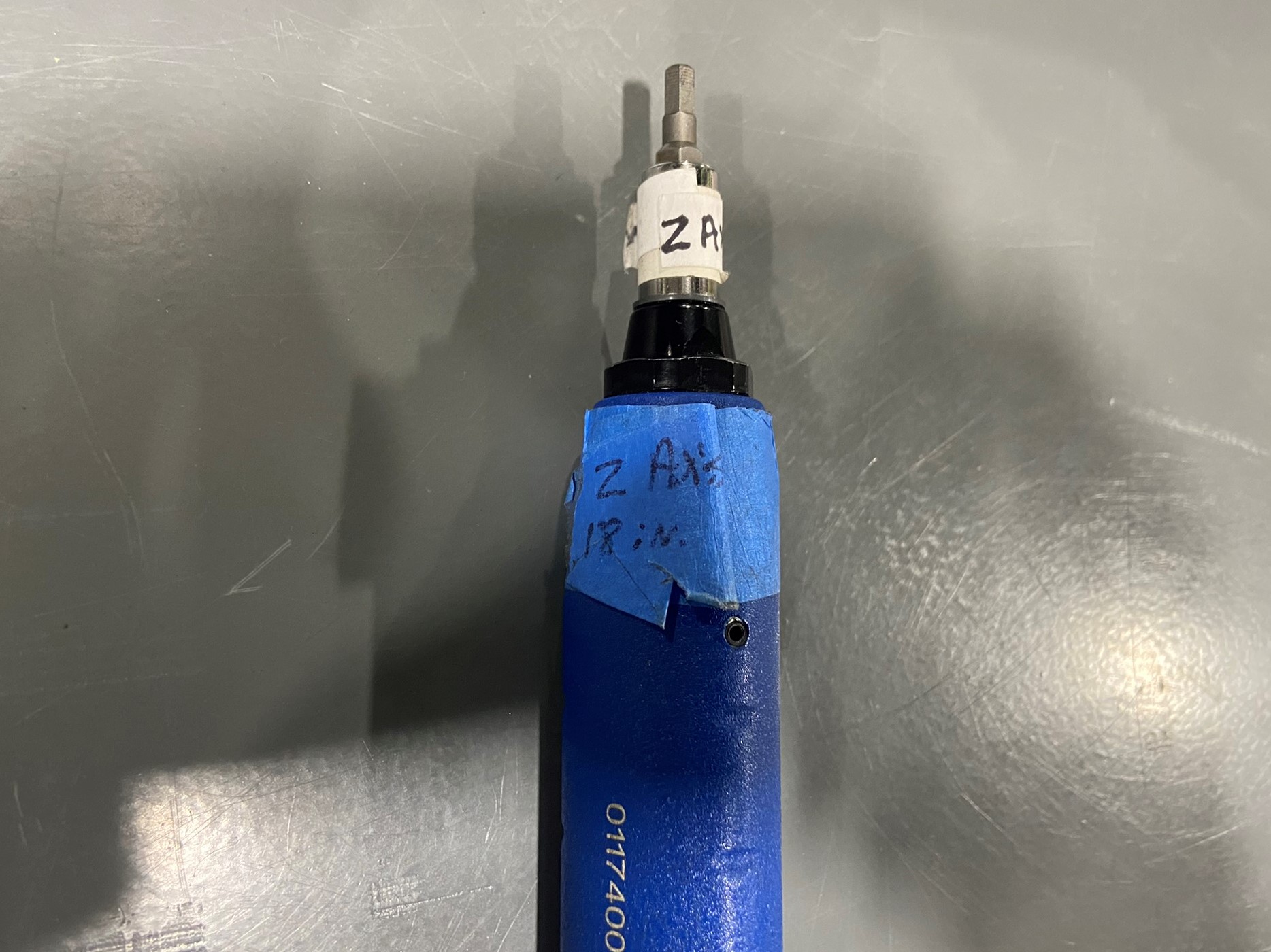
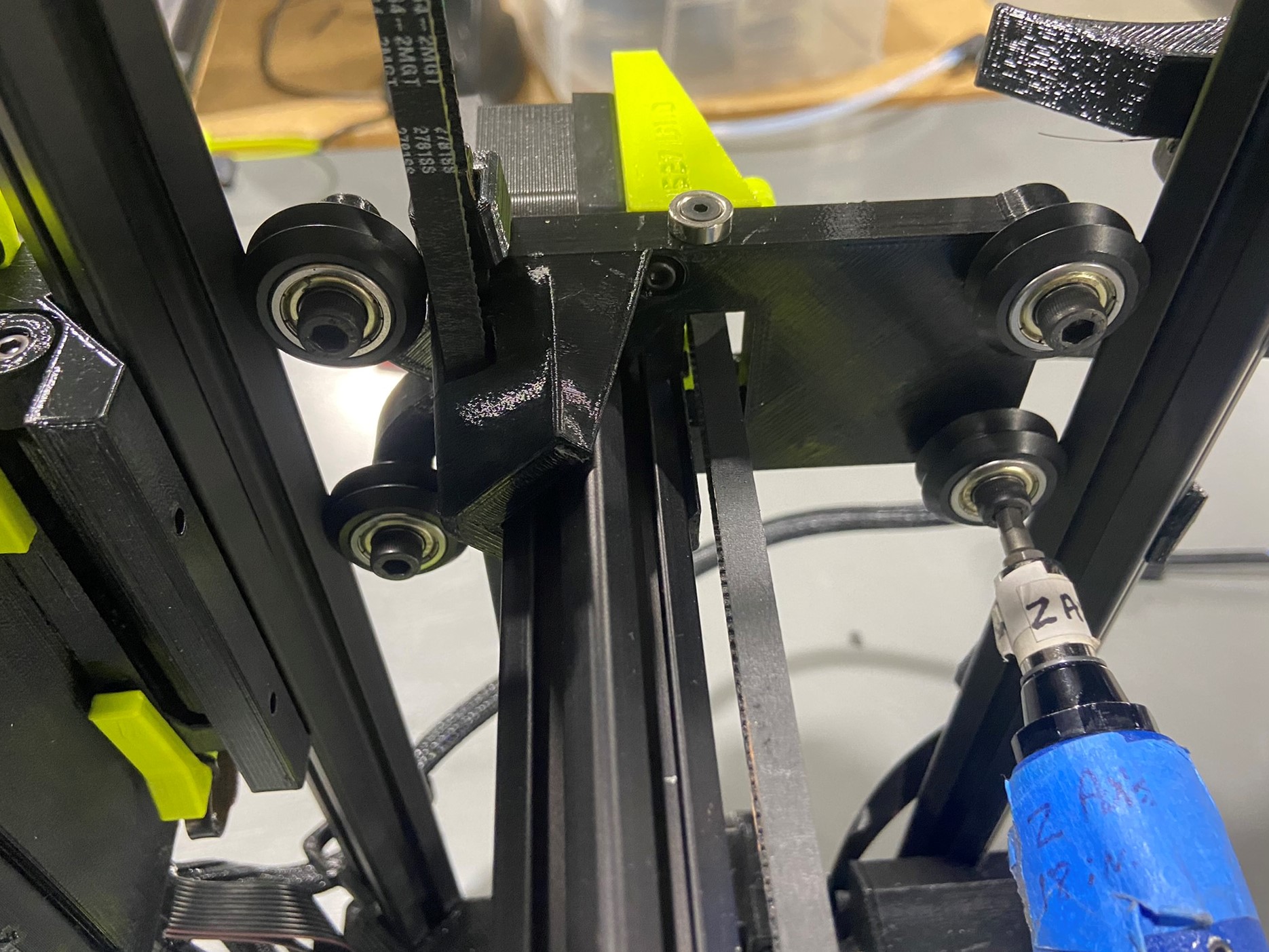
Repeat process for the X motor and X idler and use the Z axis torque driver (set at 18in*lbs) and check each wheel this your finger to see if they spin in place.
Once again if there was any wheel that failed the torque check or spun in place without the carriage or X end moving make a note of each wheel that failed and continue with the Pre-Calibration checklist.

Start with the 2.5 mm bolts:
Then check the 3 mm bolts:
Start with the M3 washers:
Then check the M5 washers:
Check all Extrusions making sure they are all fully seated inside the printed parts. There should be no gap and the extrusions should be completely inside the channels on the printed parts.
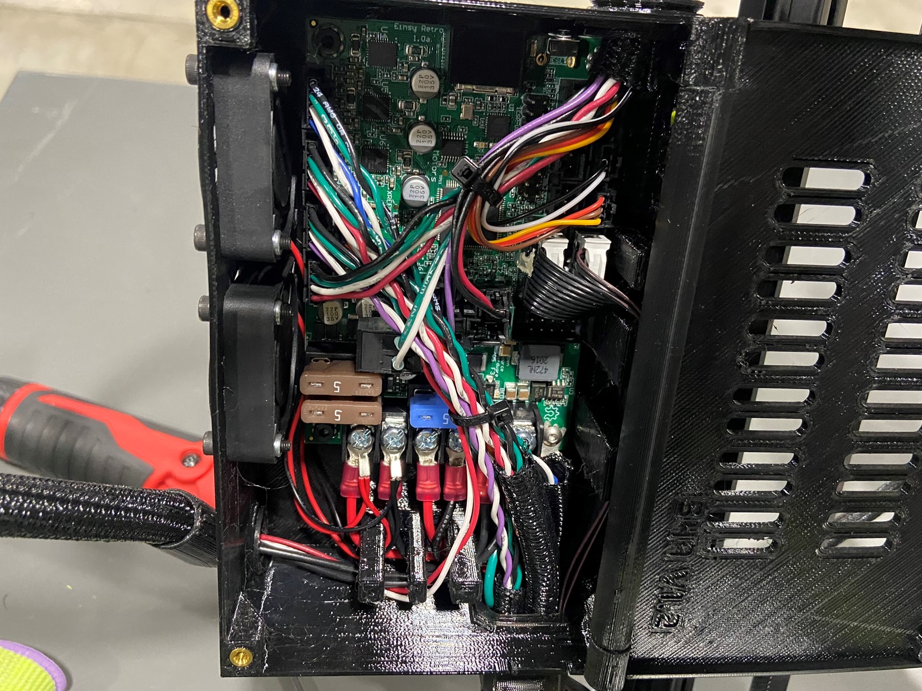
Open the control box and gently tug on the six wires that are connected to the screw terminals. Make sure none of the wires give or move around.
If the wires are able to move tighten the screw
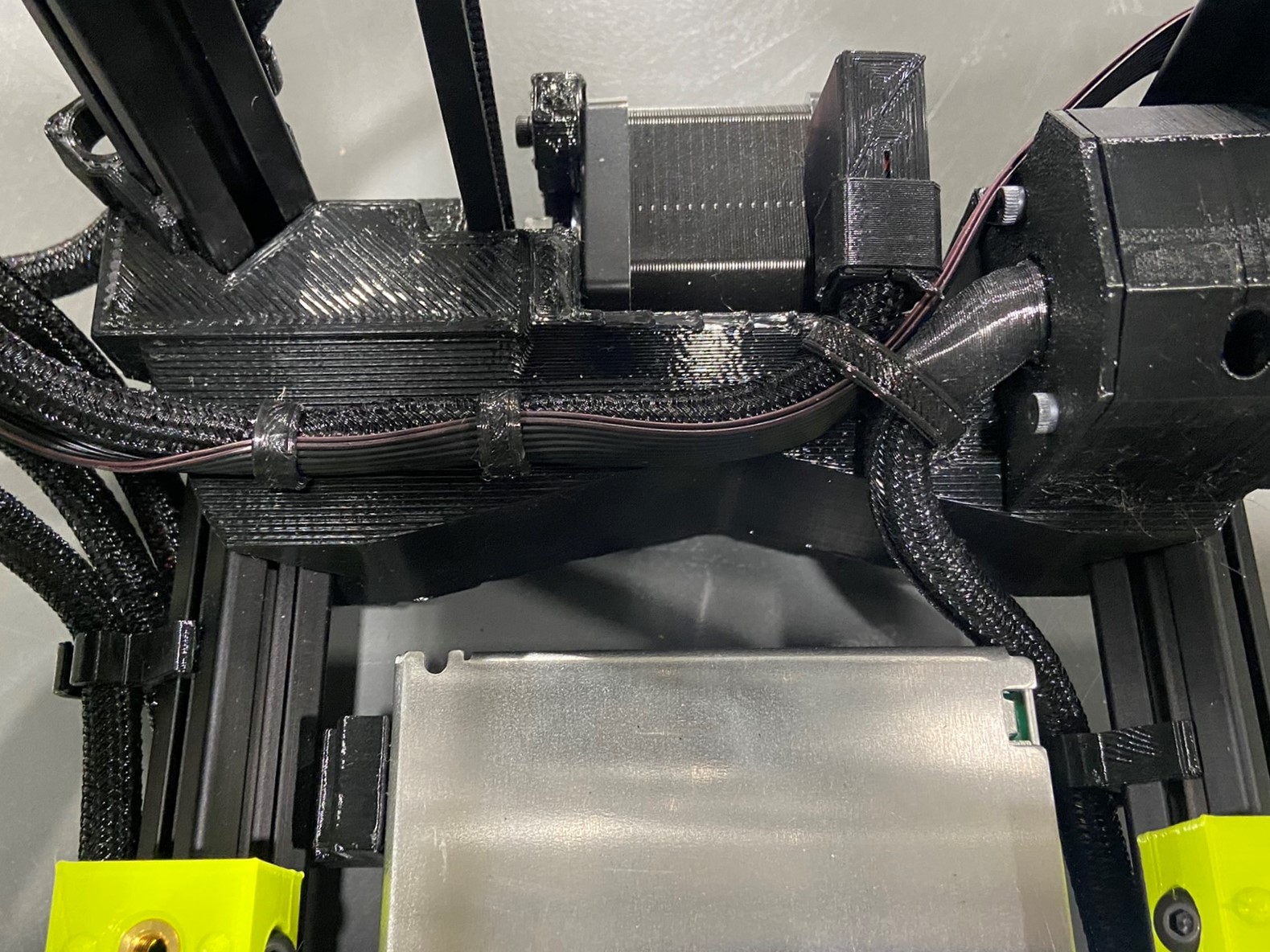
Next check the organization of the wires, each printer will look slightly different but make sure both cable ties are securing all the wires.
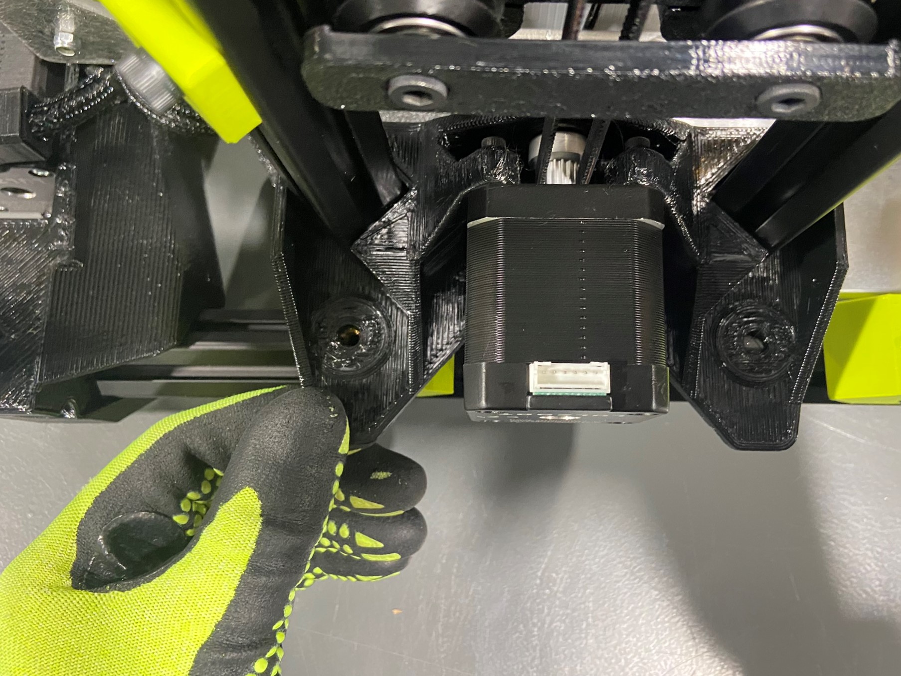
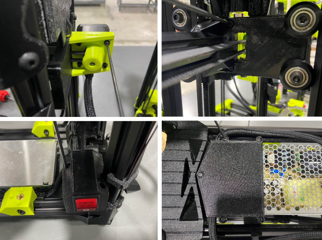
Check the fans and make sure there isn't any loose wires that could get caught in the fans or rub against the fans.
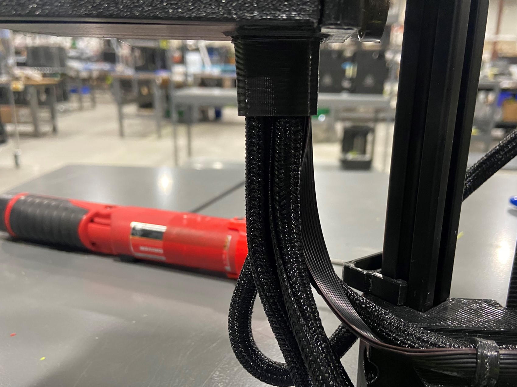
Now check the square grommet located at the bottom of the control box, make sure the wire harnesses are organize. (i.e. if the wire goes to the right Z motor make sure the wires is on the right side of the grommet)
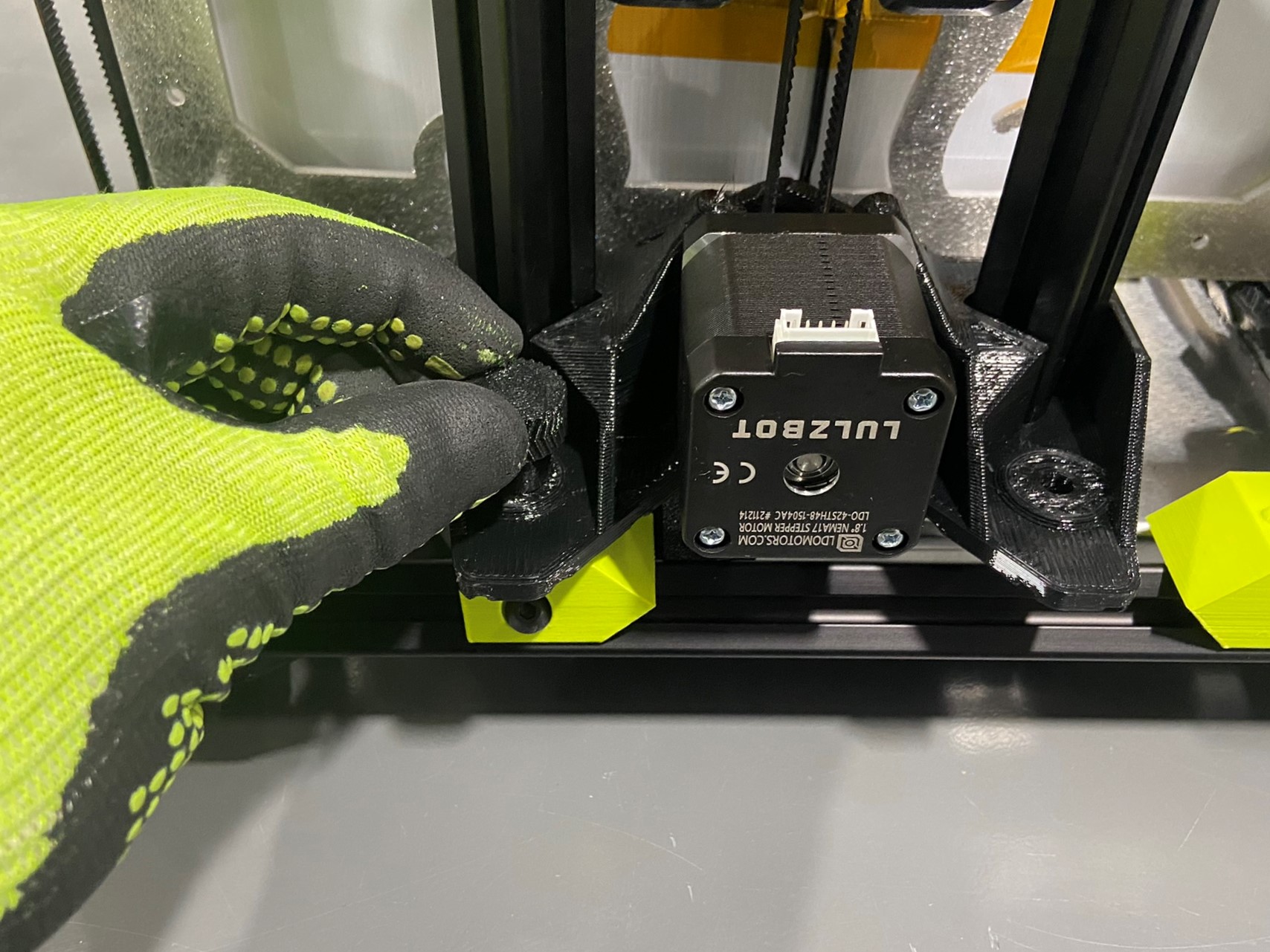
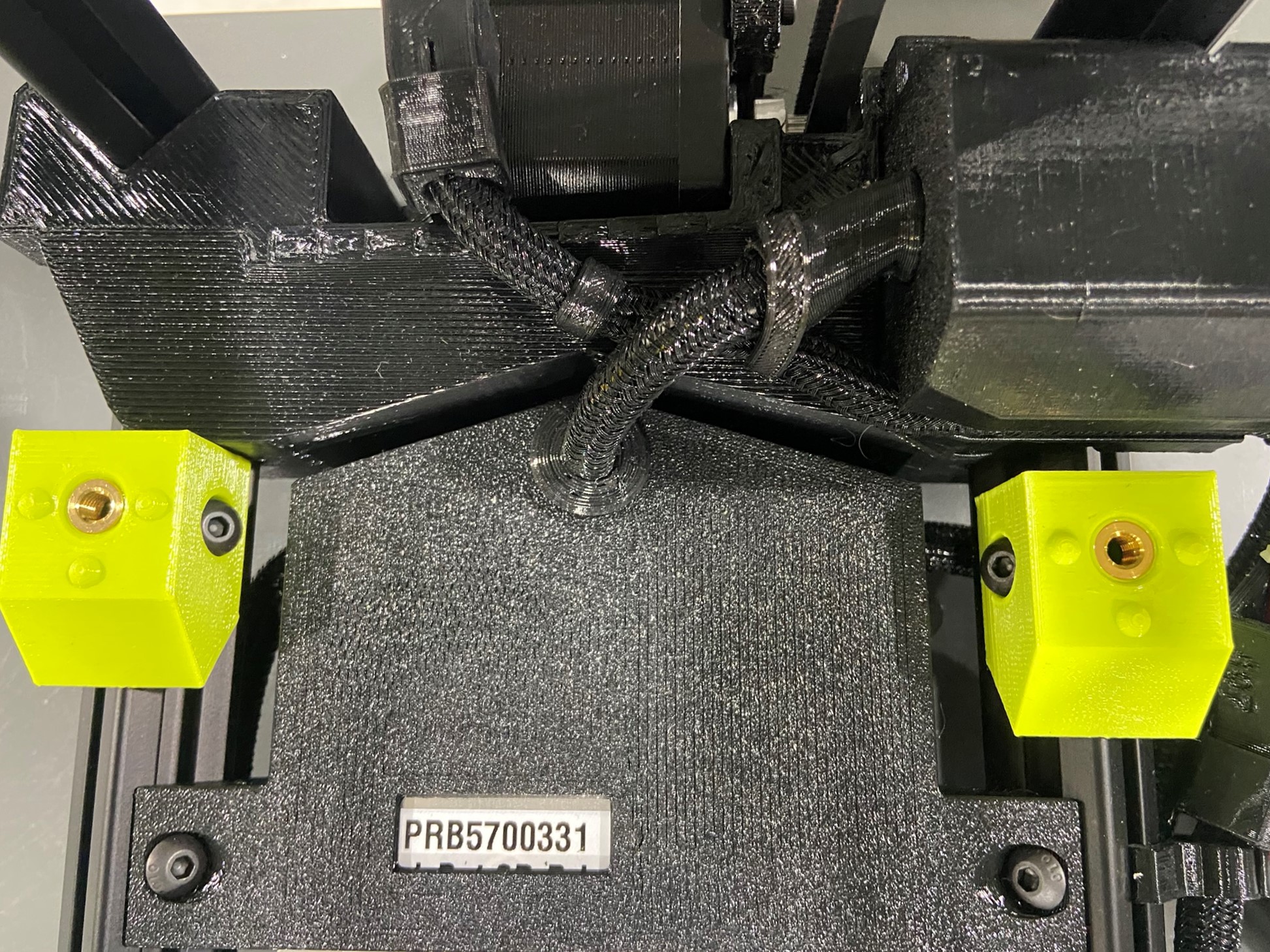
Next look at the right Z lower and make sure the rosebuds are in place and secure. Gently pull up on the rosebuds, if you are able to completely remove them with little force replace it with a new one. The 289 SK will have one longer rosebud with two smaller ones and the 747 SK will have three long rosebuds.
We will repeat the process with the left Z lower, on this side the 289 & 747 SK will both have a long and short rosebud.
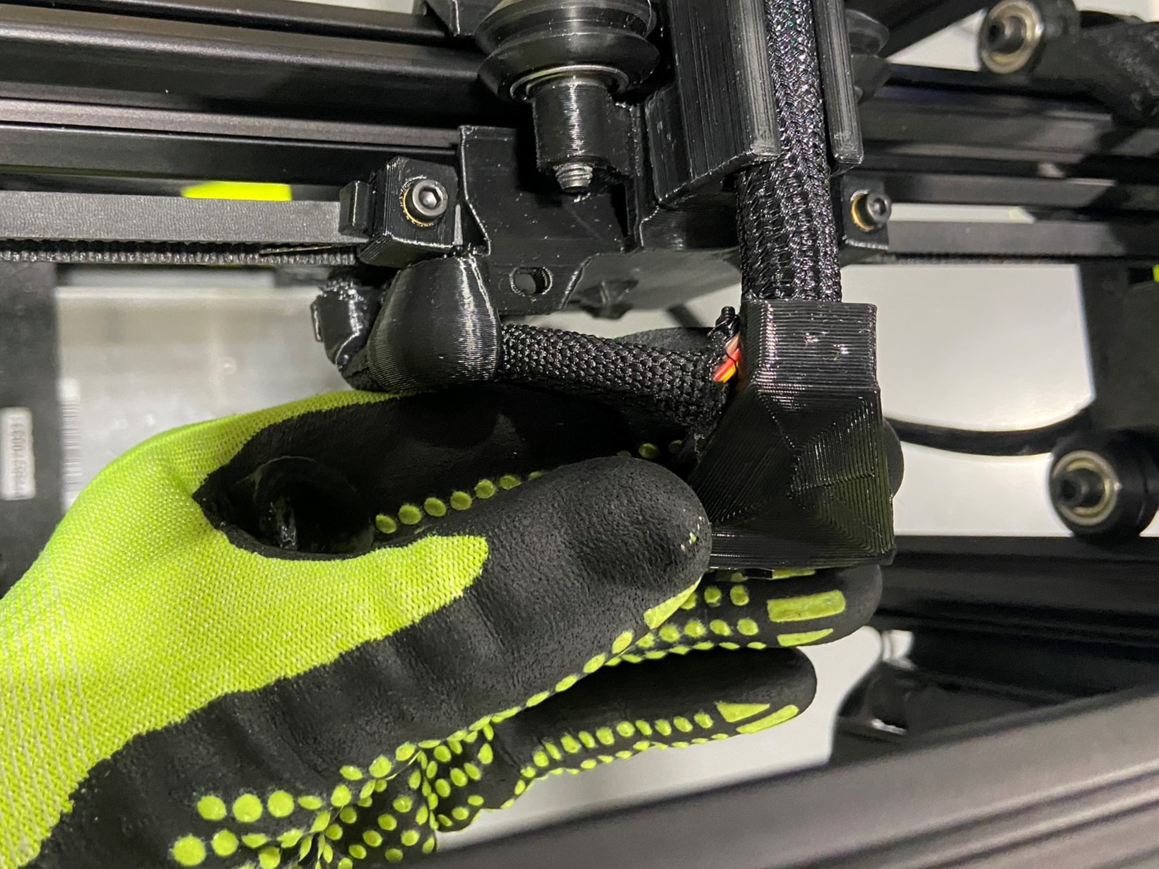
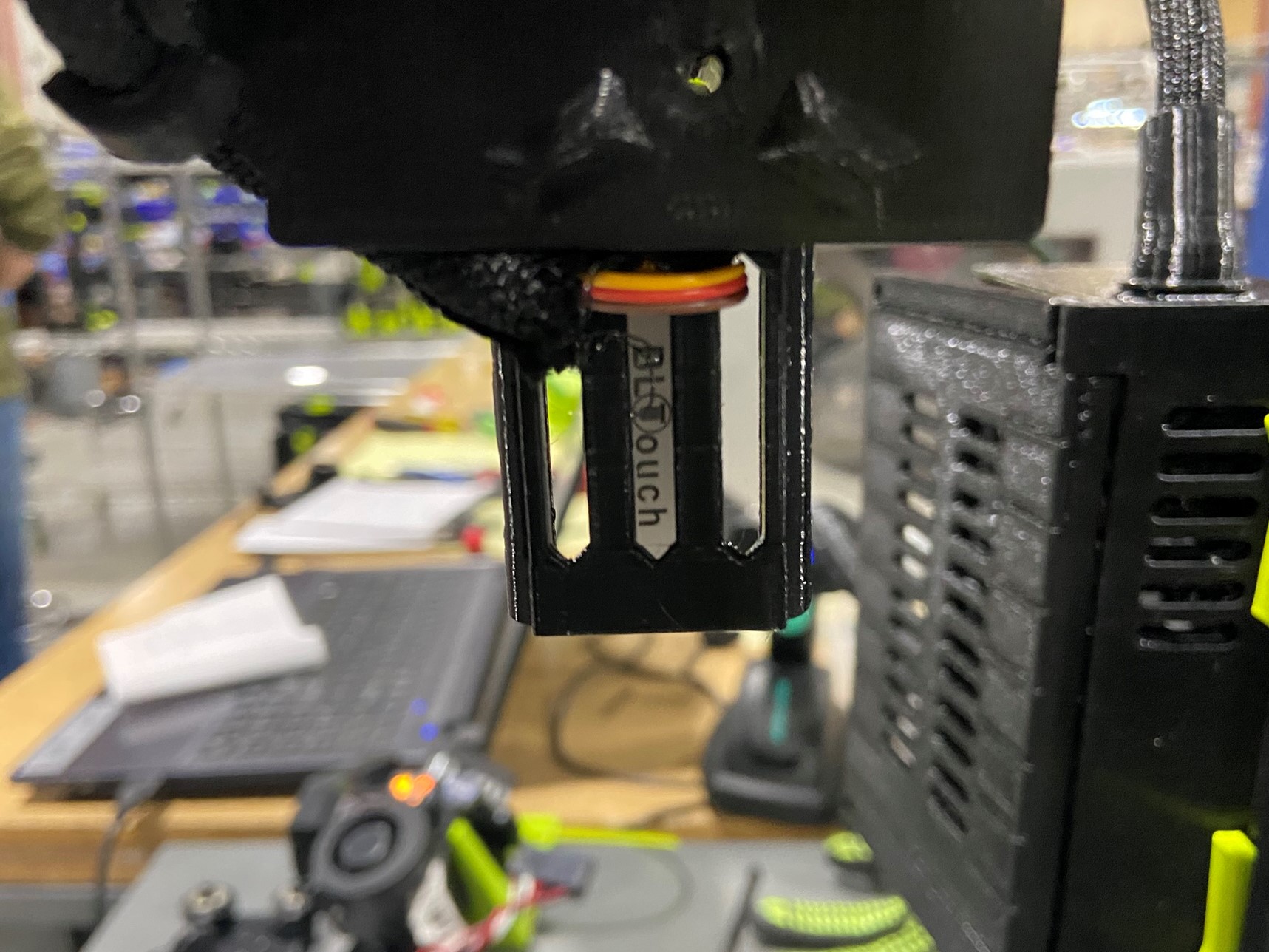
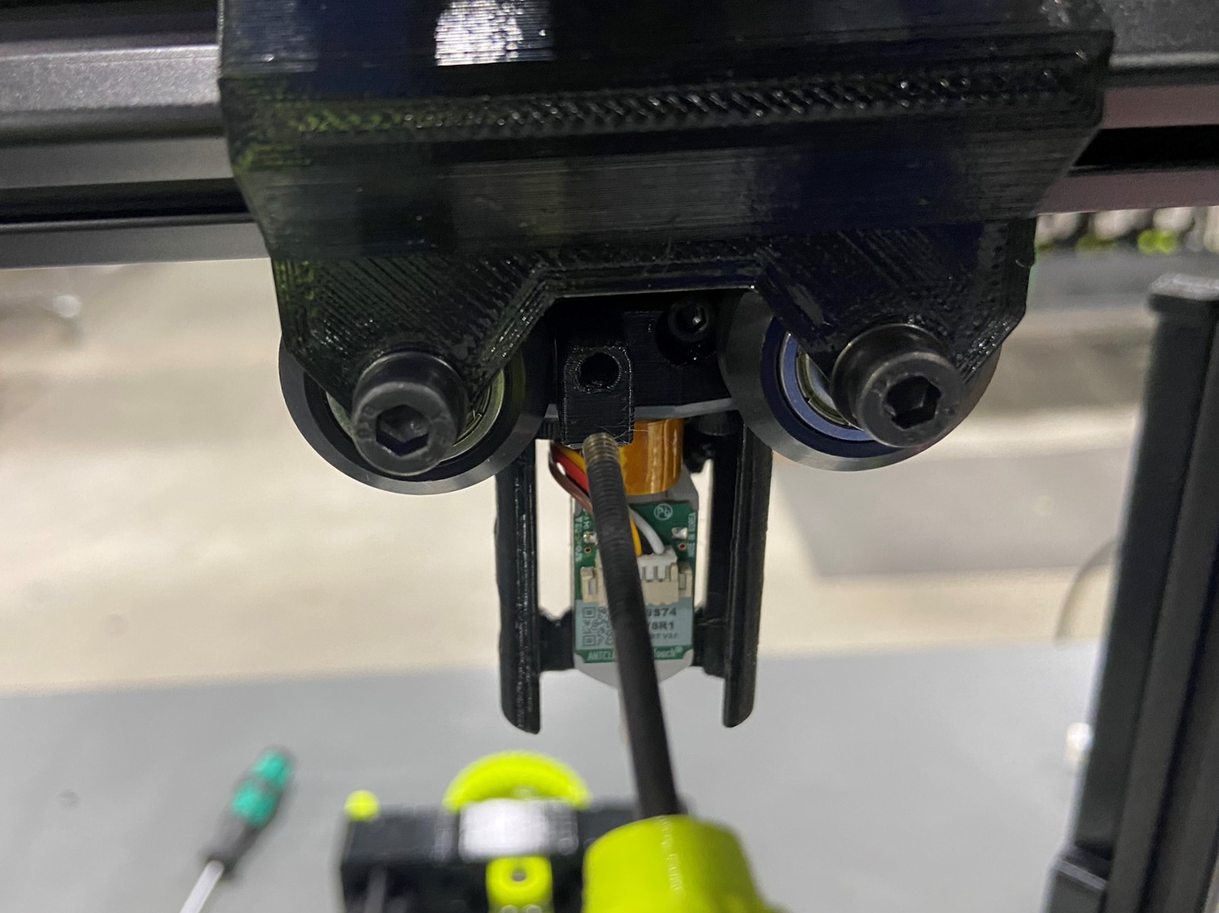
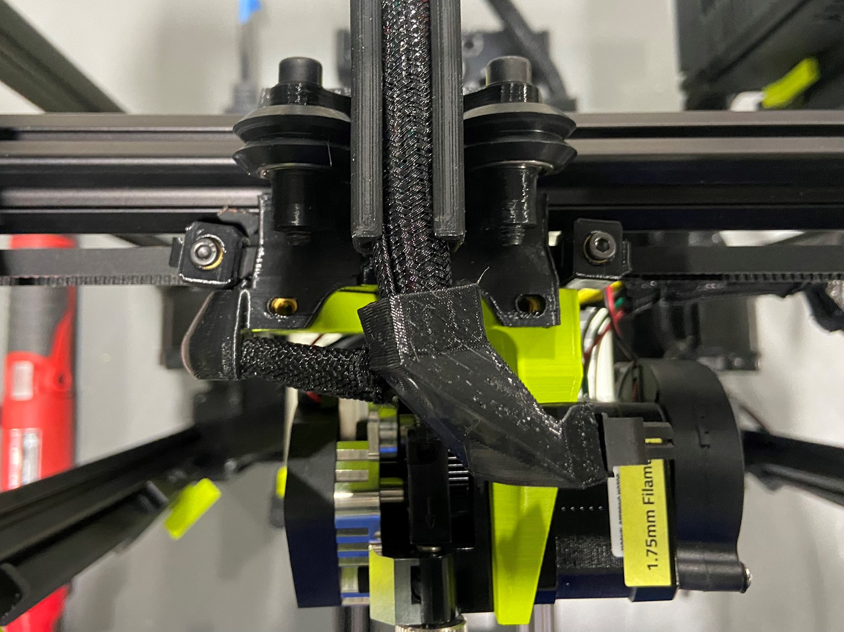
Now make sure the BLT harness is routed through the slit on the tool head boot, if it isn't pull the braid out of the boot and align the BLT harness with the slit and push the harness back inside the boot.
Then follow the BLT harness through both channels on the X carriage and make sure the harness is routed through the right slot on the BLT mount. Also make sure the BLTouch has a secure connection.


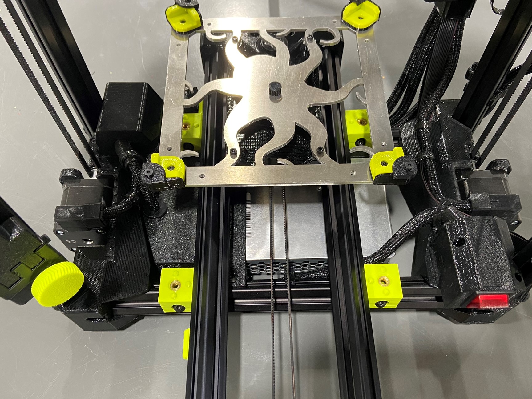
Place the Y axis that was grabbed previously and set it inside the printer making sure the Y motor is on the backside of the printer. Then attach four calibration frame clamps to the four Y axis frame mounts.
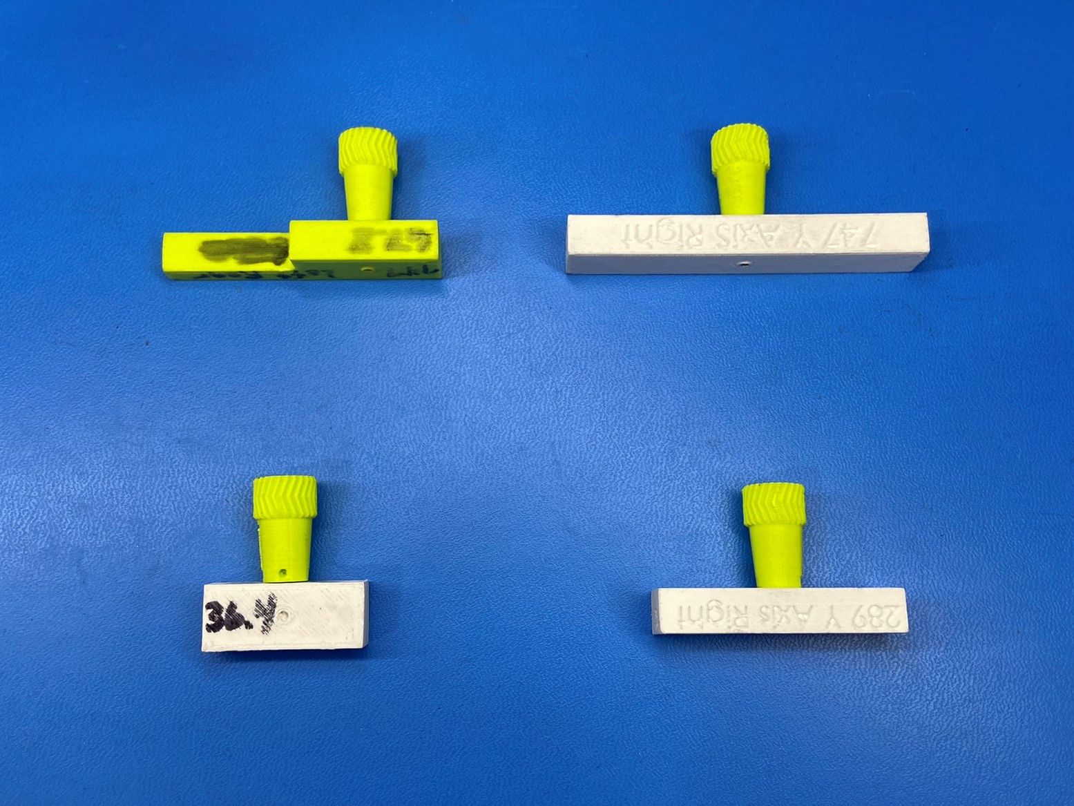
Now depending on the size of the printer use the two Y axis jigs to secure the frame mounts to the extrusion. There will be two jigs for each printer and one will correspond with the left side and one for the right. We will use the same jig for the front and back side.
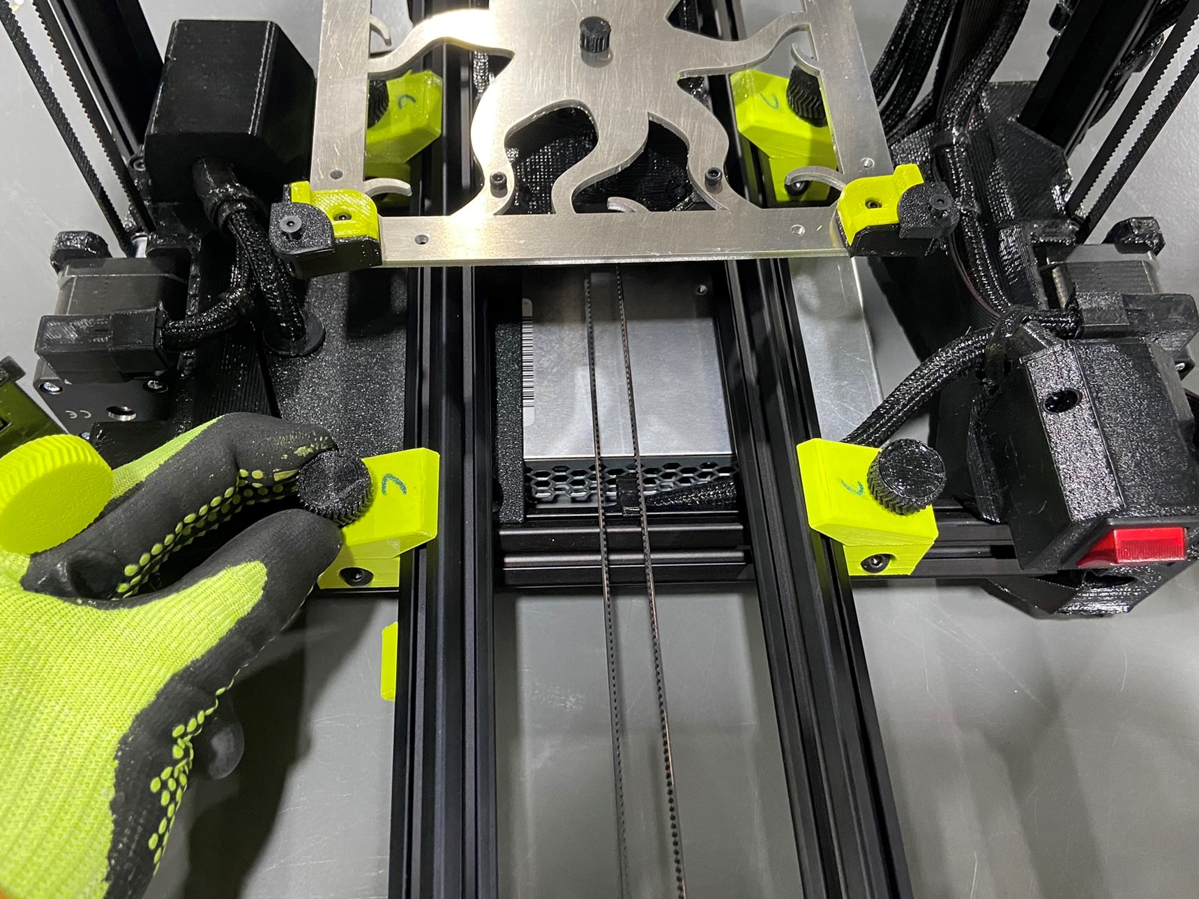
Align the rear Y axis placement block with the backside of the left rear frame mount and slide the front placement block up to the front left frame mount and tighten.
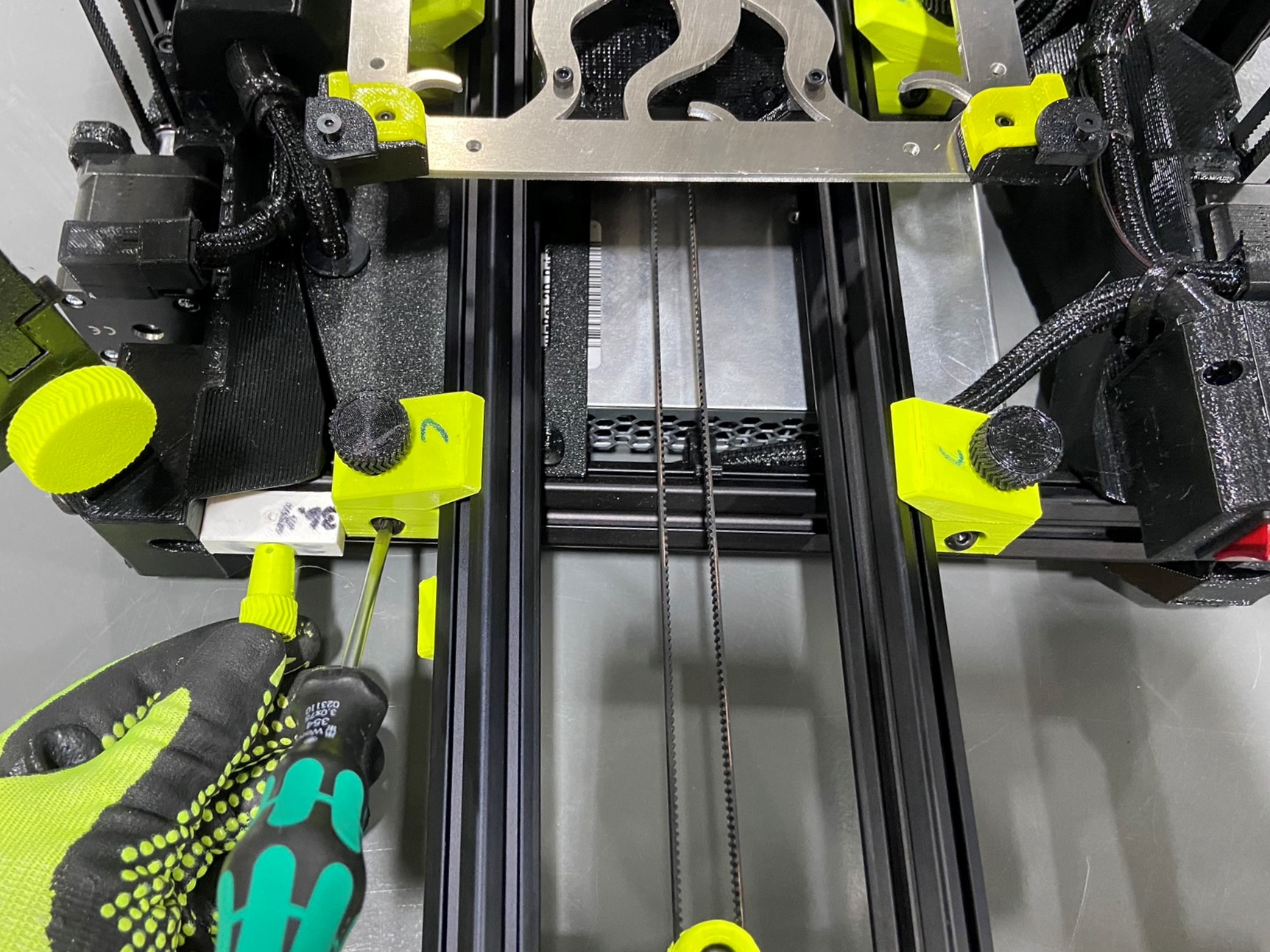

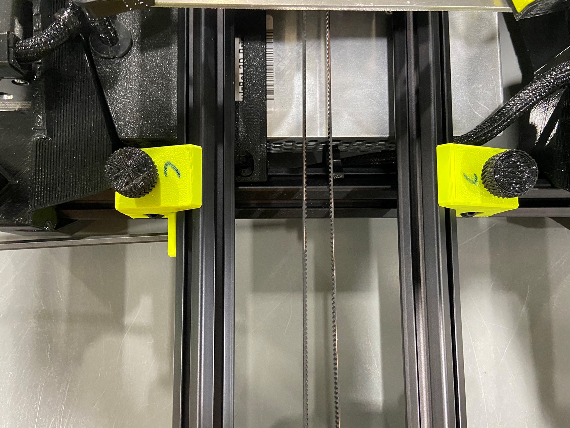
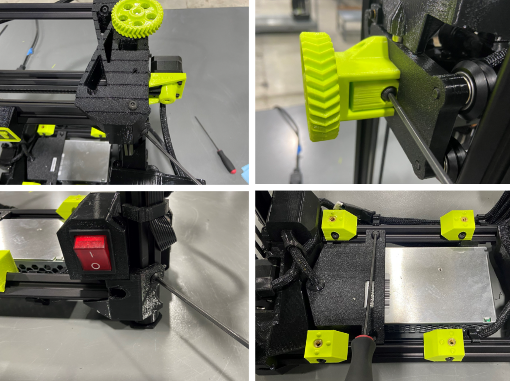
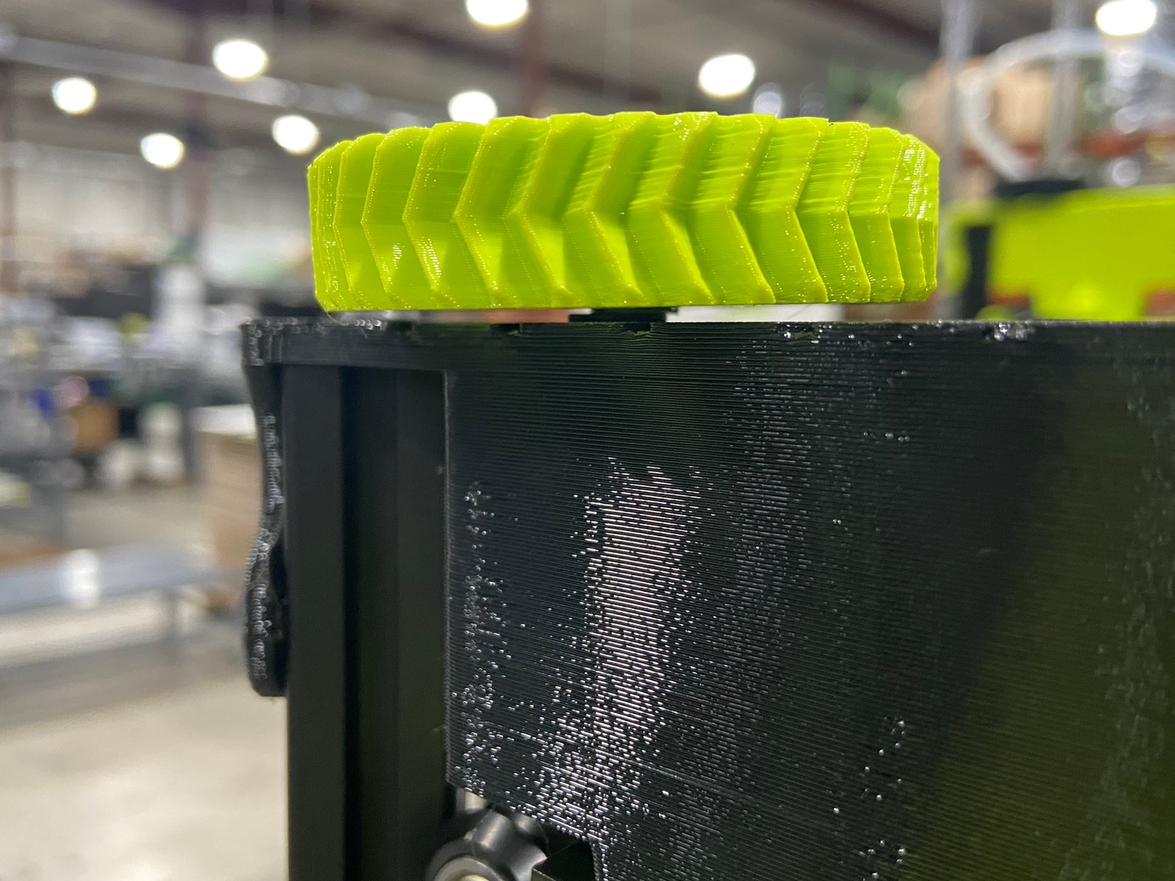
Before tensioning the belts, check all the XYZ tension knobs ensuring that the screw is flush will the nylon part of the nut and that the belt is somewhat tight.
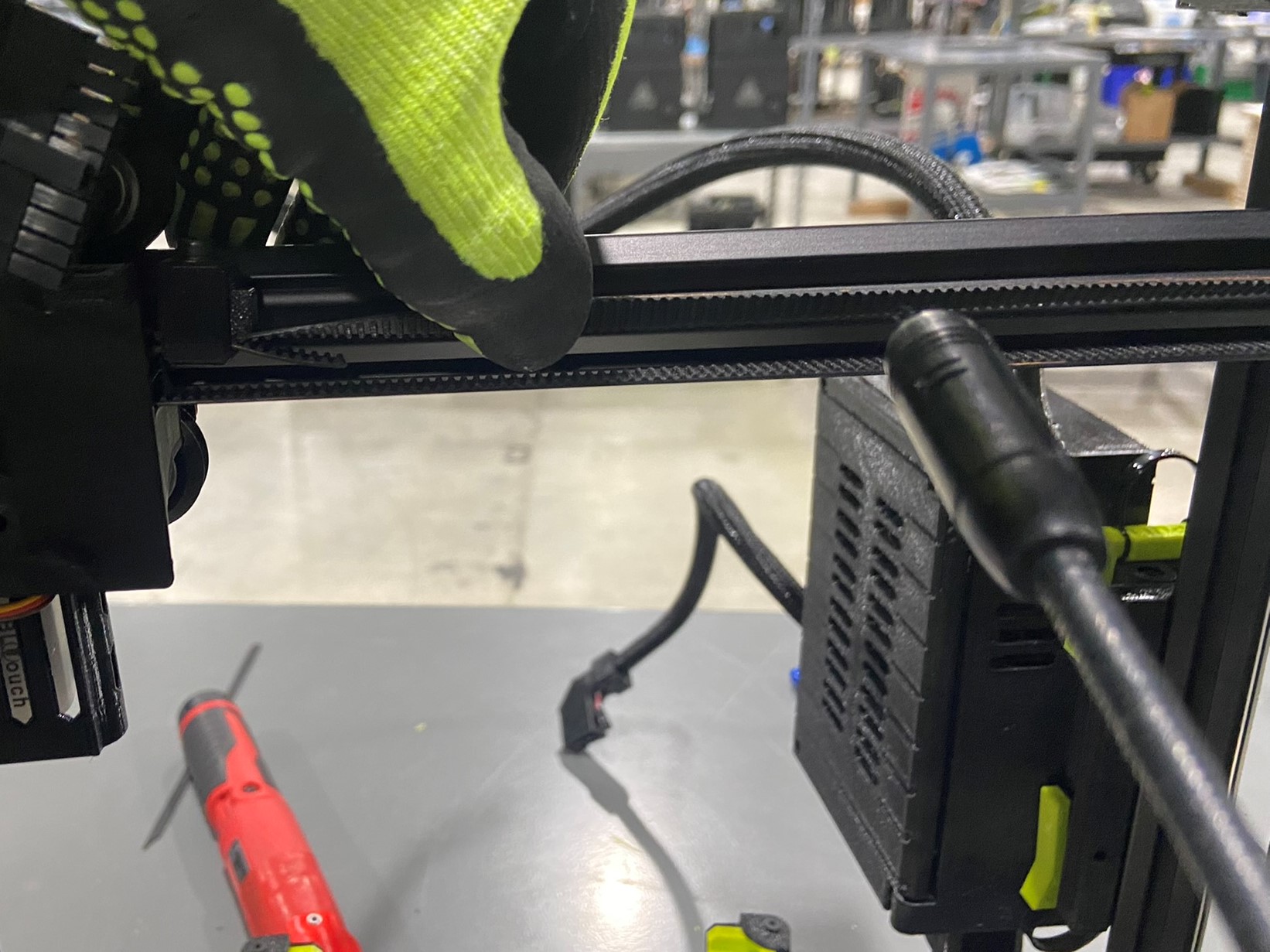
Once all the tension knobs are checked take the Ultrasonic Belt Tensioner and turn it on.
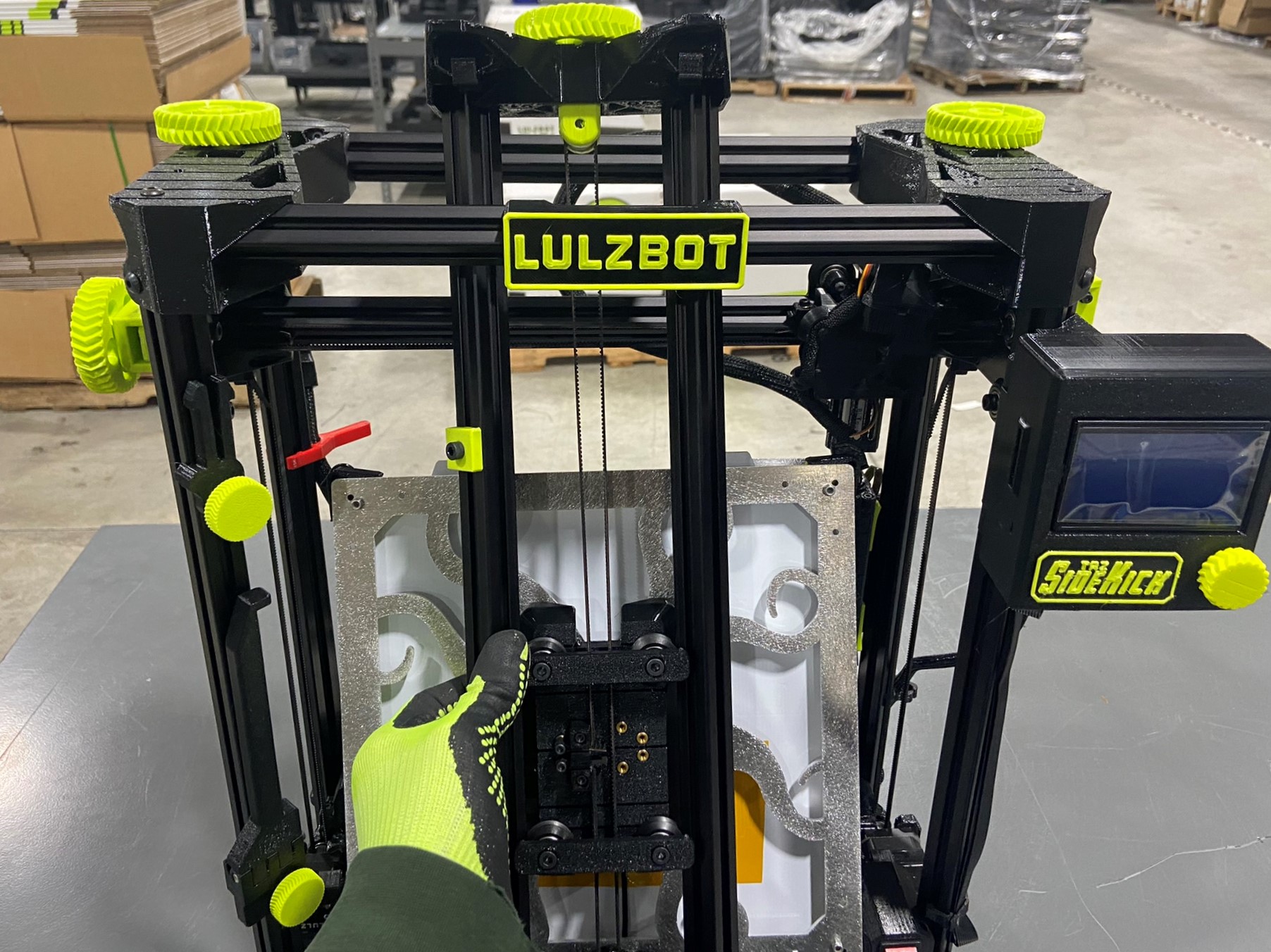
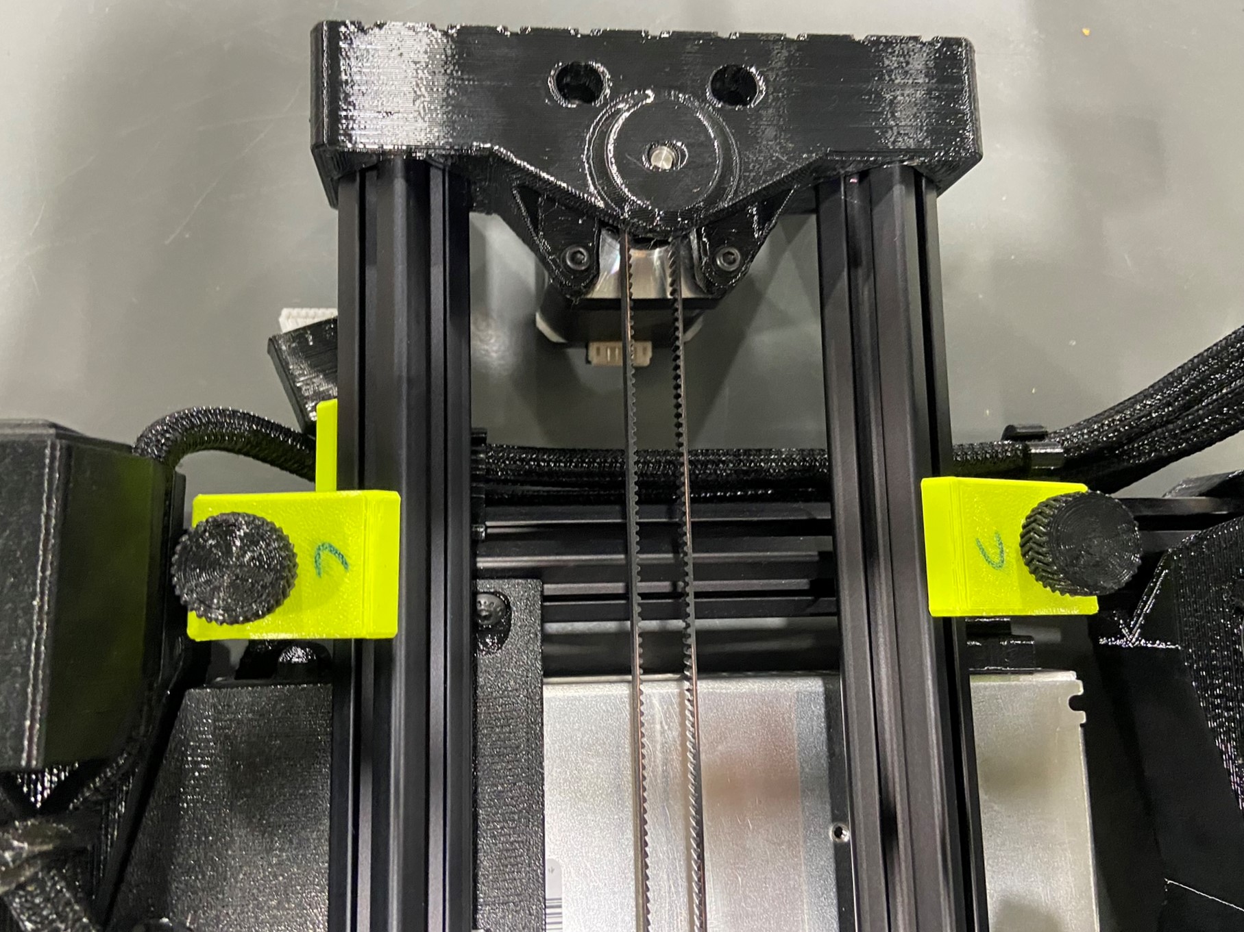
In order to get an accurate belt tension measurement, the printer has to be in a certain orientation. Start with the X axis all the way up making sure the magnets on the Z uppers and X ends are close to touching.
Then slide the X carriage all the way to the left side of the printer.
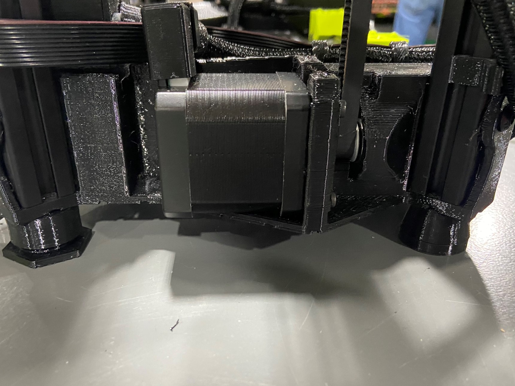
Then push the Y carriage all the way back so it is touching the Y motor mount.
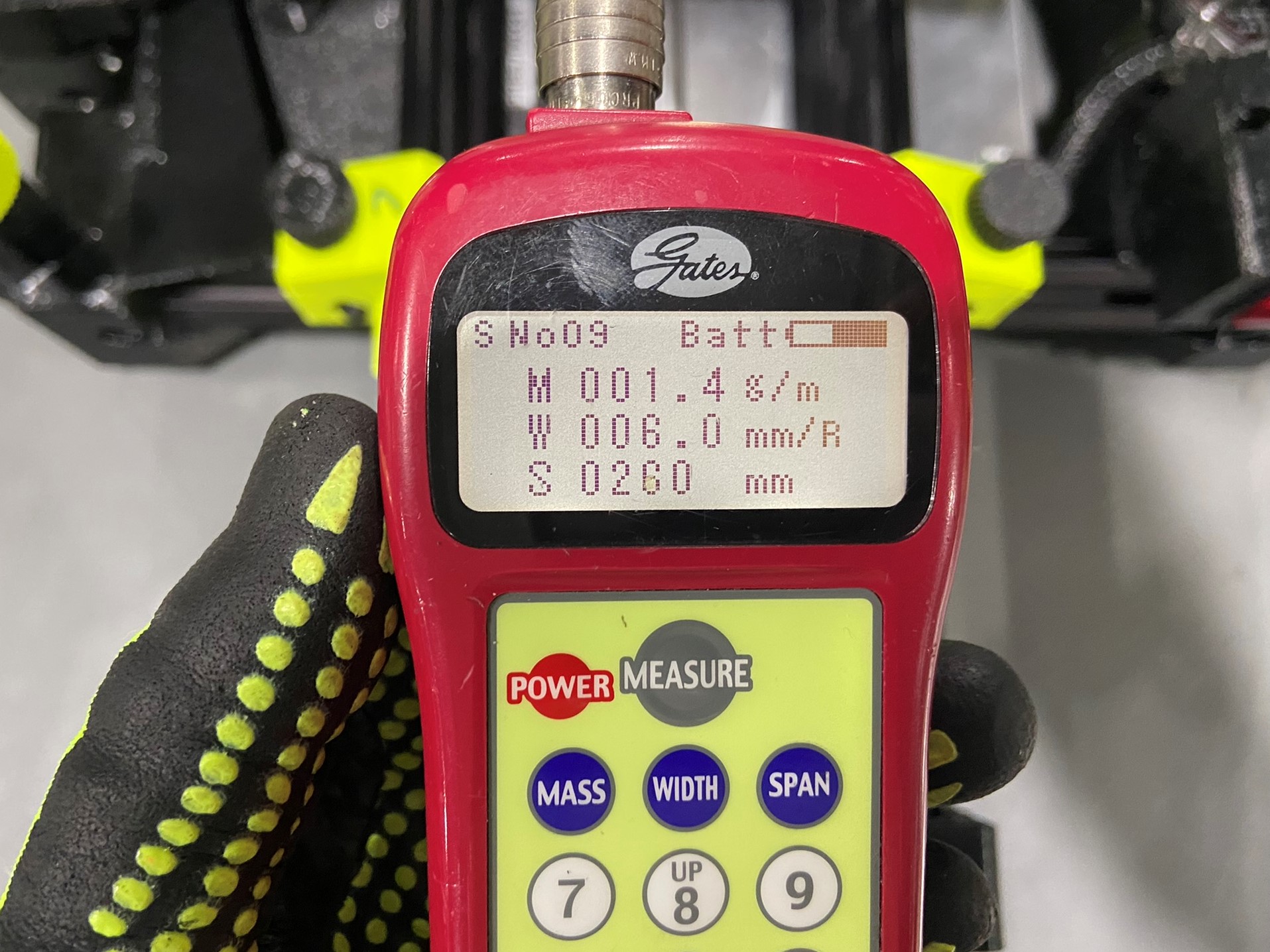
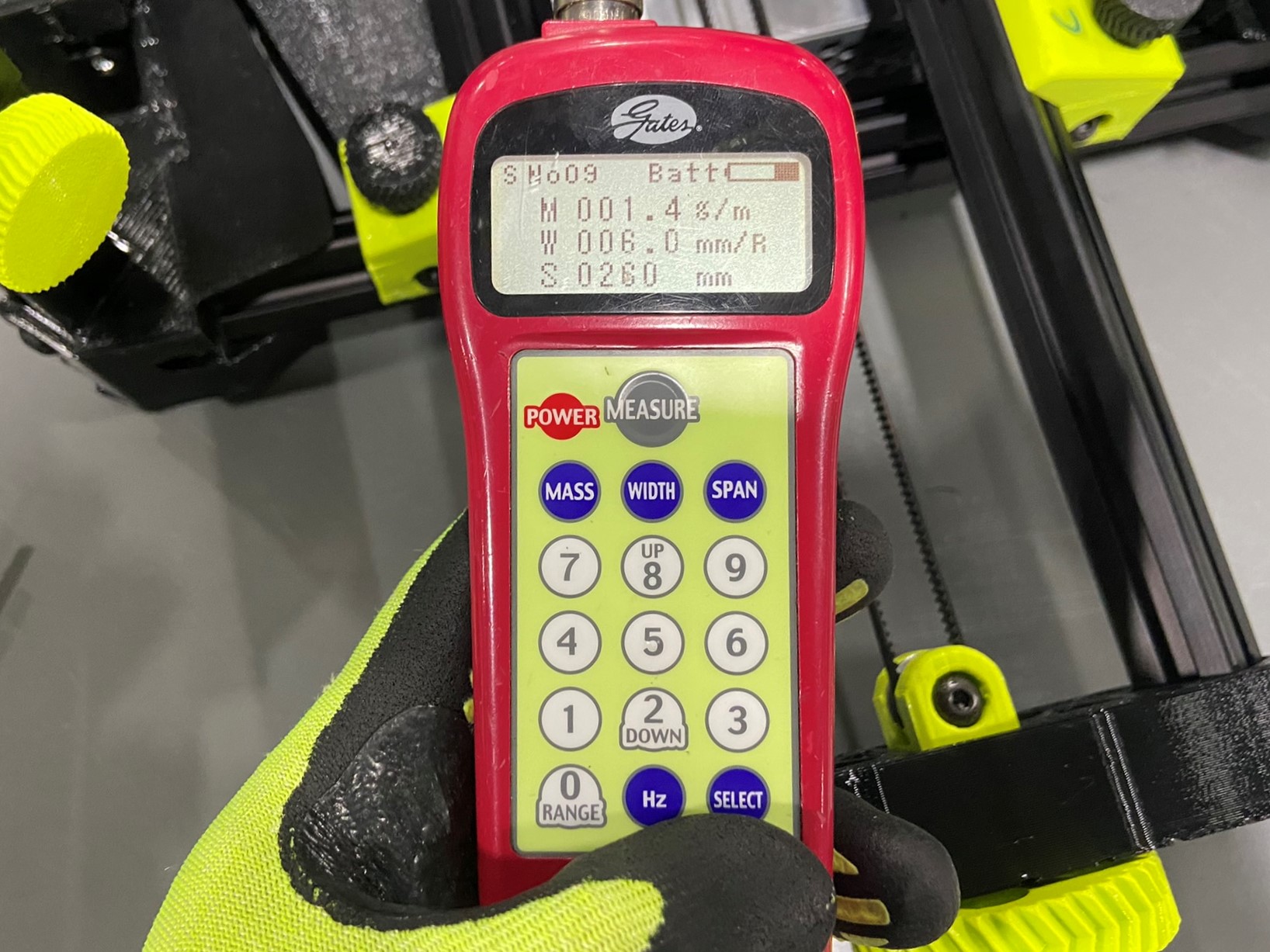
To change settings on the belt tensioner you have to press the "SELECT" button and type in the setting number. Then if you press "SELECT" again the belt tension will move up one setting.
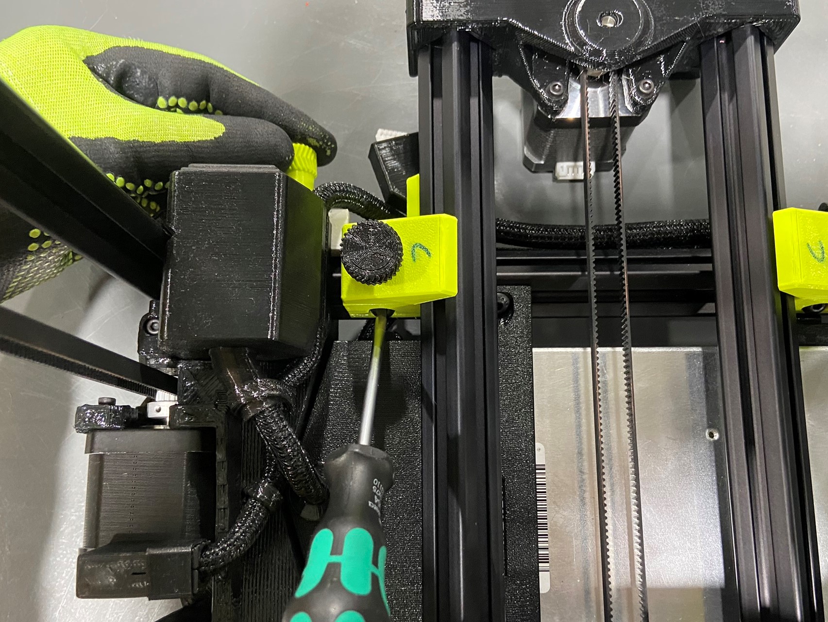
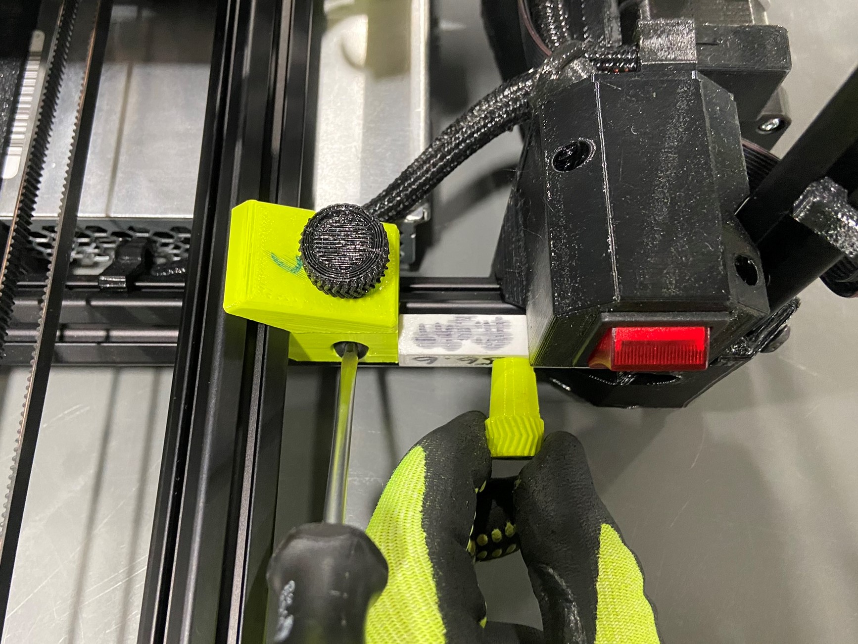
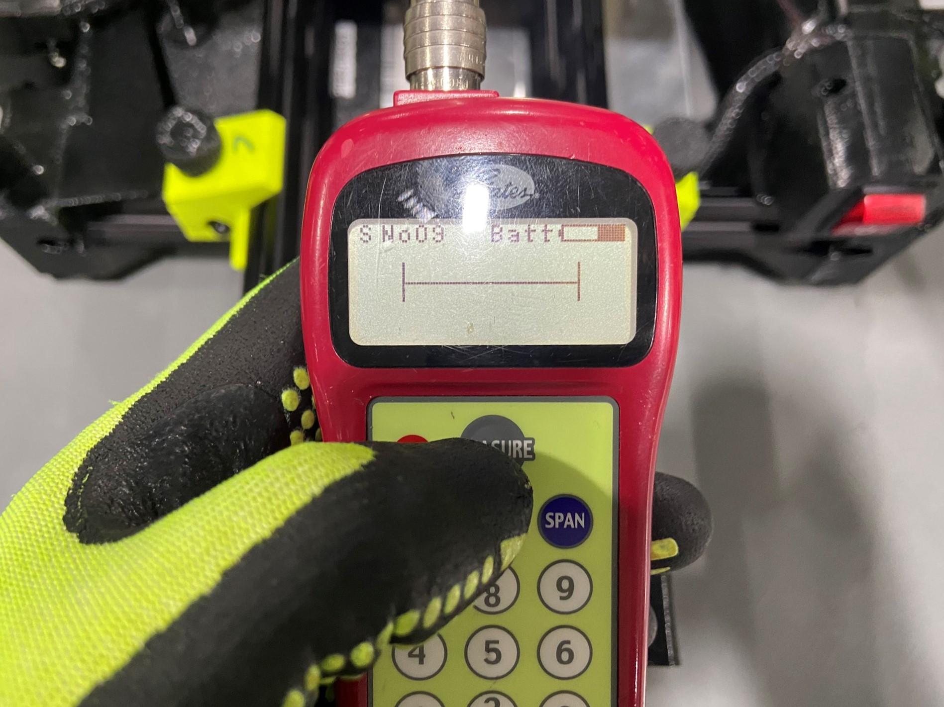
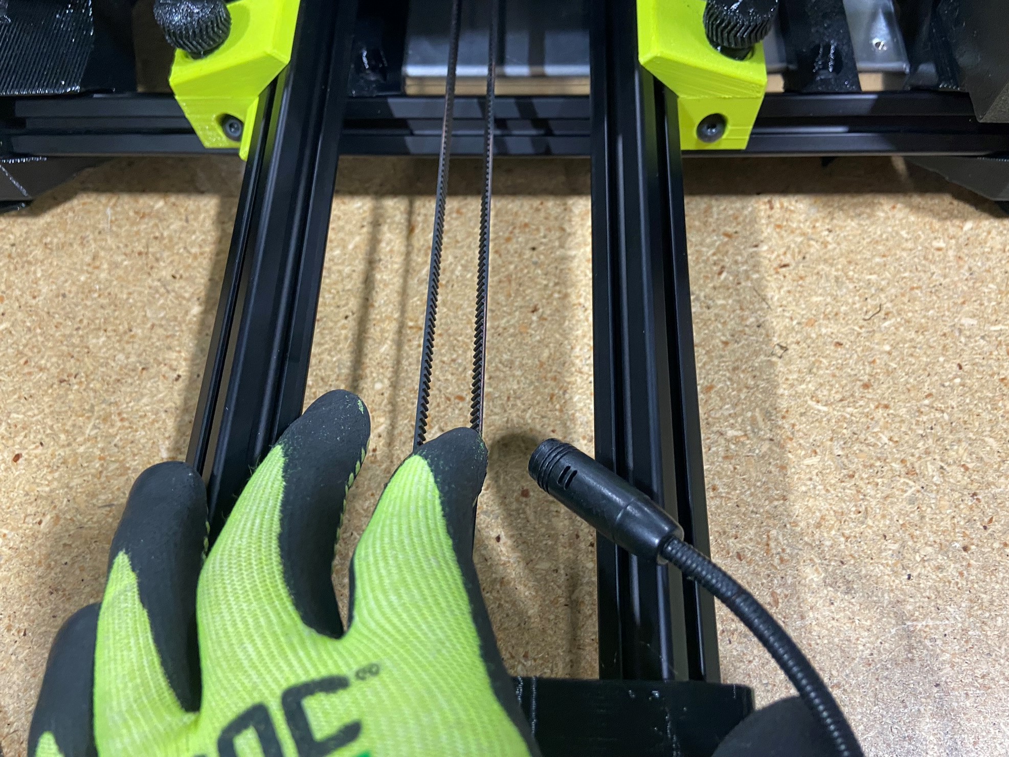
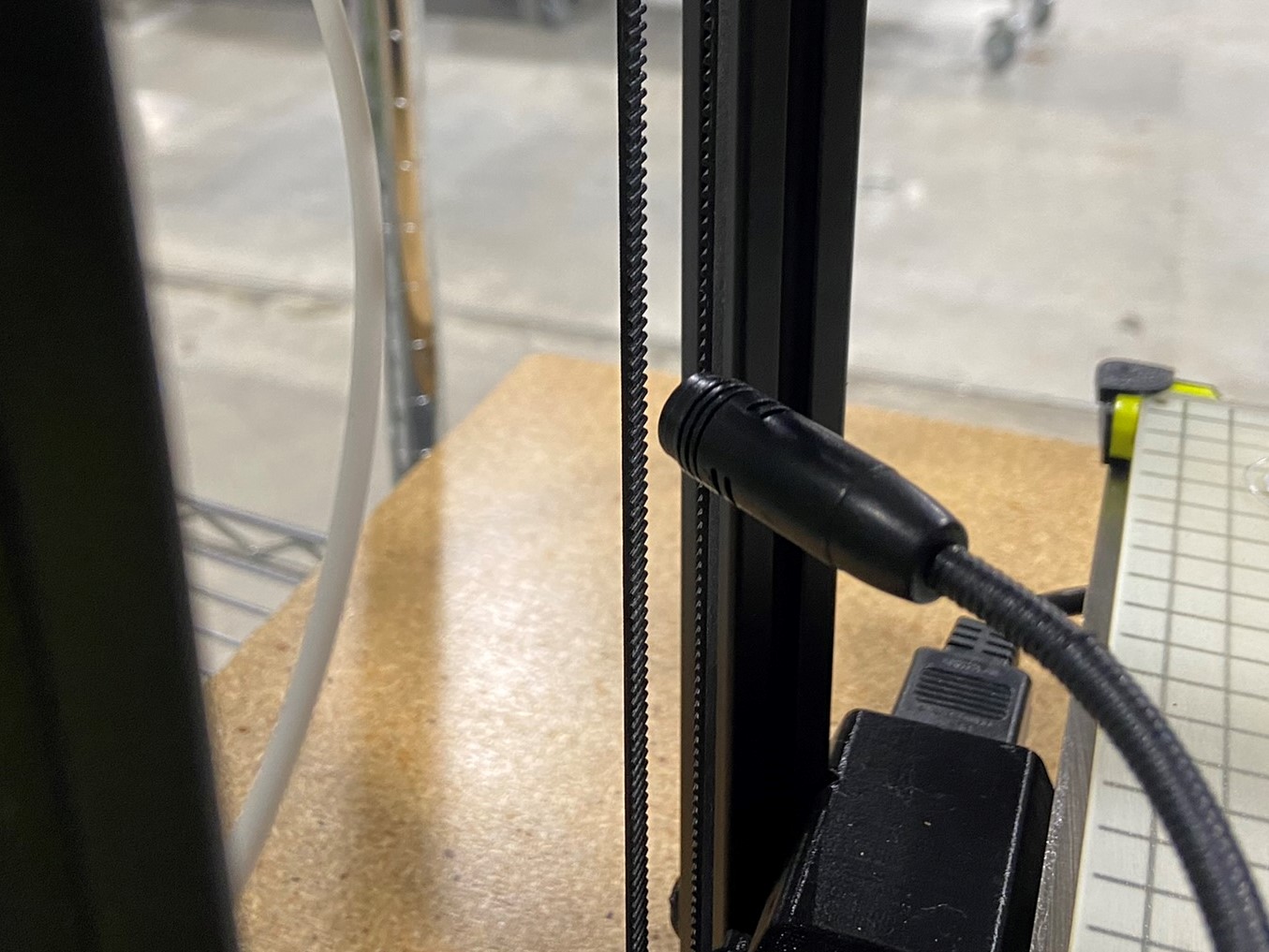
To measure the belts you have to press "MEASURE" and a line will pop up on the screen, then pluck the designated side of the belt and hold the microphone close to the belt. If this process is done correctly the belt tensioner will show the tension in N. We will tension each axis to 35N ± 1N make sure both Z axis tensions are the same or very similar. To adjust the belt tension rotate the XYZ tension knobs.
Before moving on to the next belt make sure you get a measurement within 34-36N three times in a row, then record the last measurement on the calibration log.
The 289 & 747 SK printers will have different setting along with each axis:


If you are calibrating a MTO (Make to Order) printer take one of the calibration SE tool heads.
If you are calibrating a Kit printer use a new SK175 tool head.
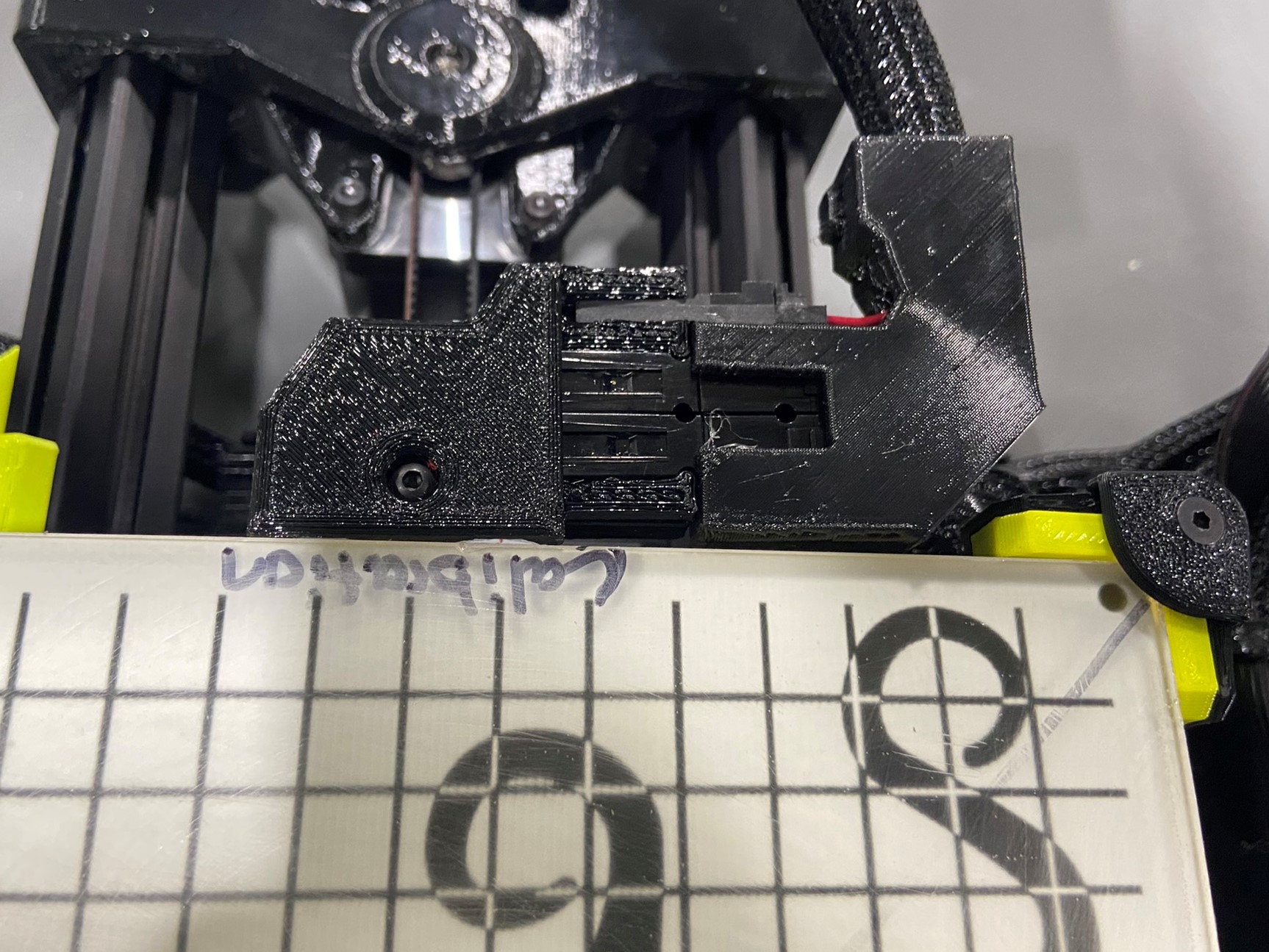
To secure the tool head to the printer you will need to the three tool head thumb screws (one long and two short). Take the long screw and going from the backside of the X carriage thread it through the hole on the BLTouch mount and align and fasten the tool head to the X carriage. Then take the two smaller screws and secure the top of the tool head.
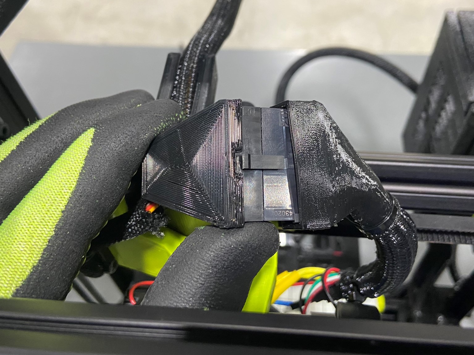
Once the tool head is attached to the printer connect the extruder harness to the tool head harness.
Take a new Heated Bed Plate and place it on the Y axis making sure the connector is on the backside.
If you are calibrating a Kit printer take a calibration glass bed plate, or if the printer is a MTO you can either use a glass or magnetic bed plate.
Place either the glass or magnetics bed plate over the heated bed plate, and align all four bed corner covers so that they hold the bed plate in place and then tighten the four screws. If you are using a magnetic bed plate make sure there is a spring steel printer surface over the magnetic plate.
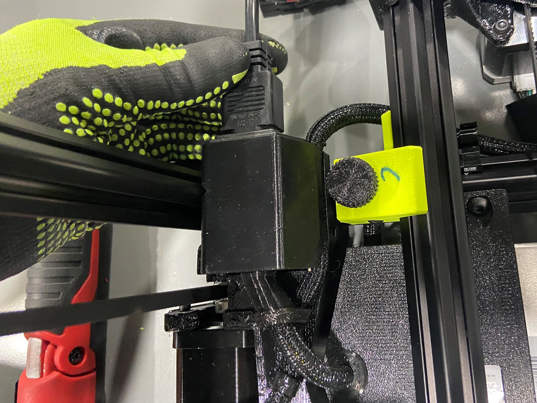
Then connect the heated bed plate to the printer using the bed harness connected to the side of the control box.


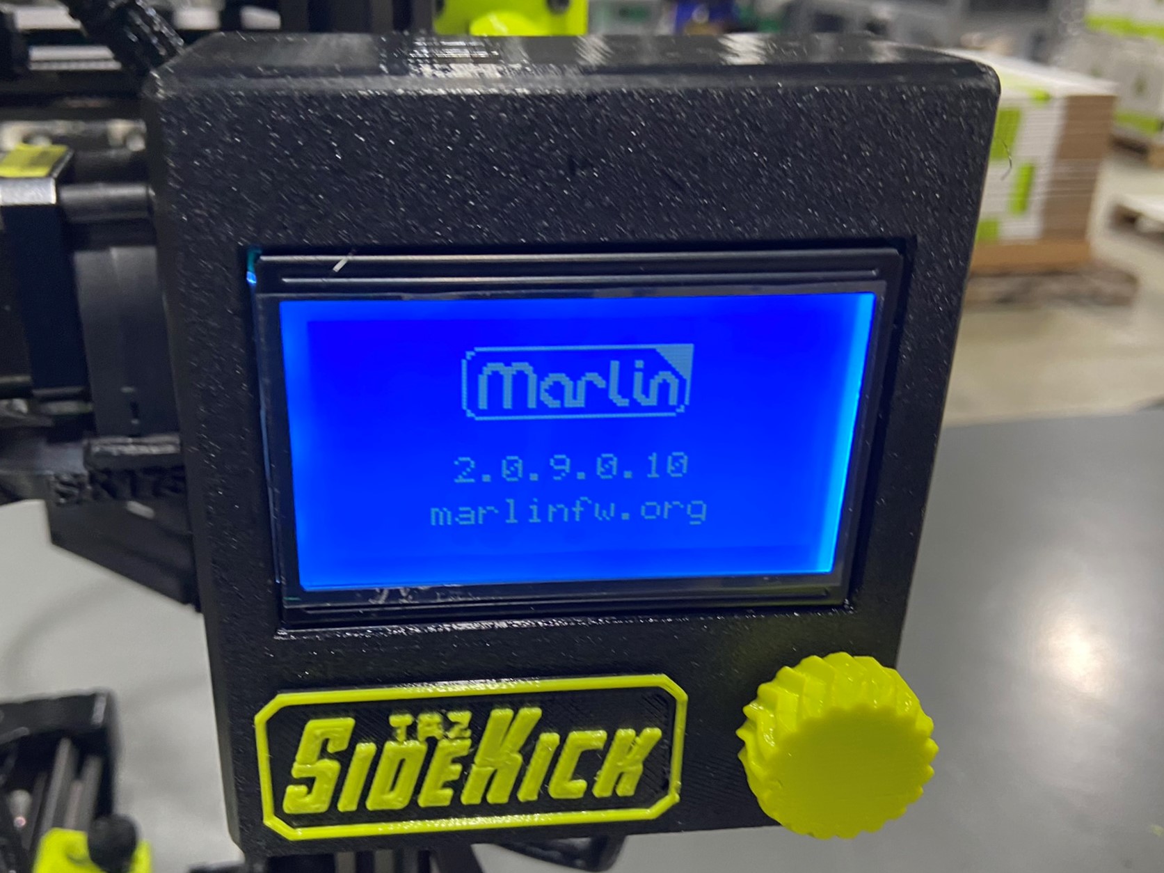
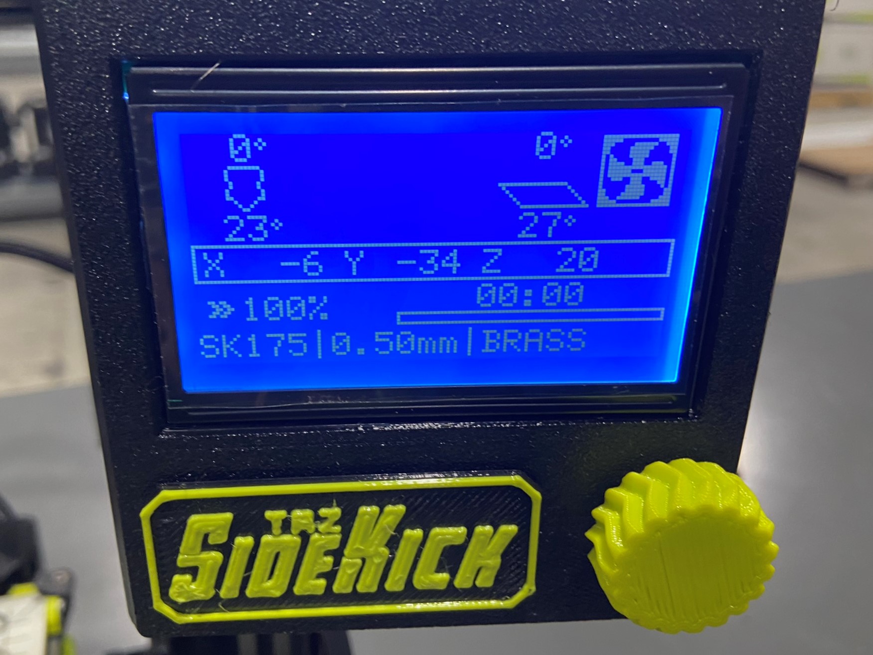
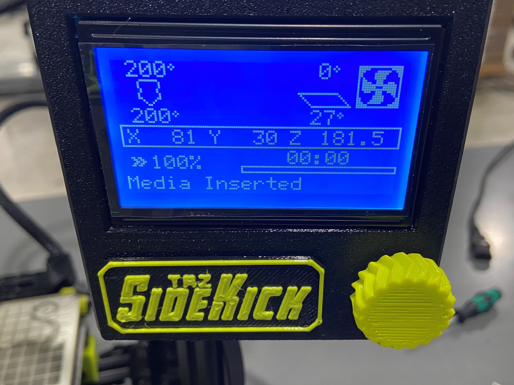
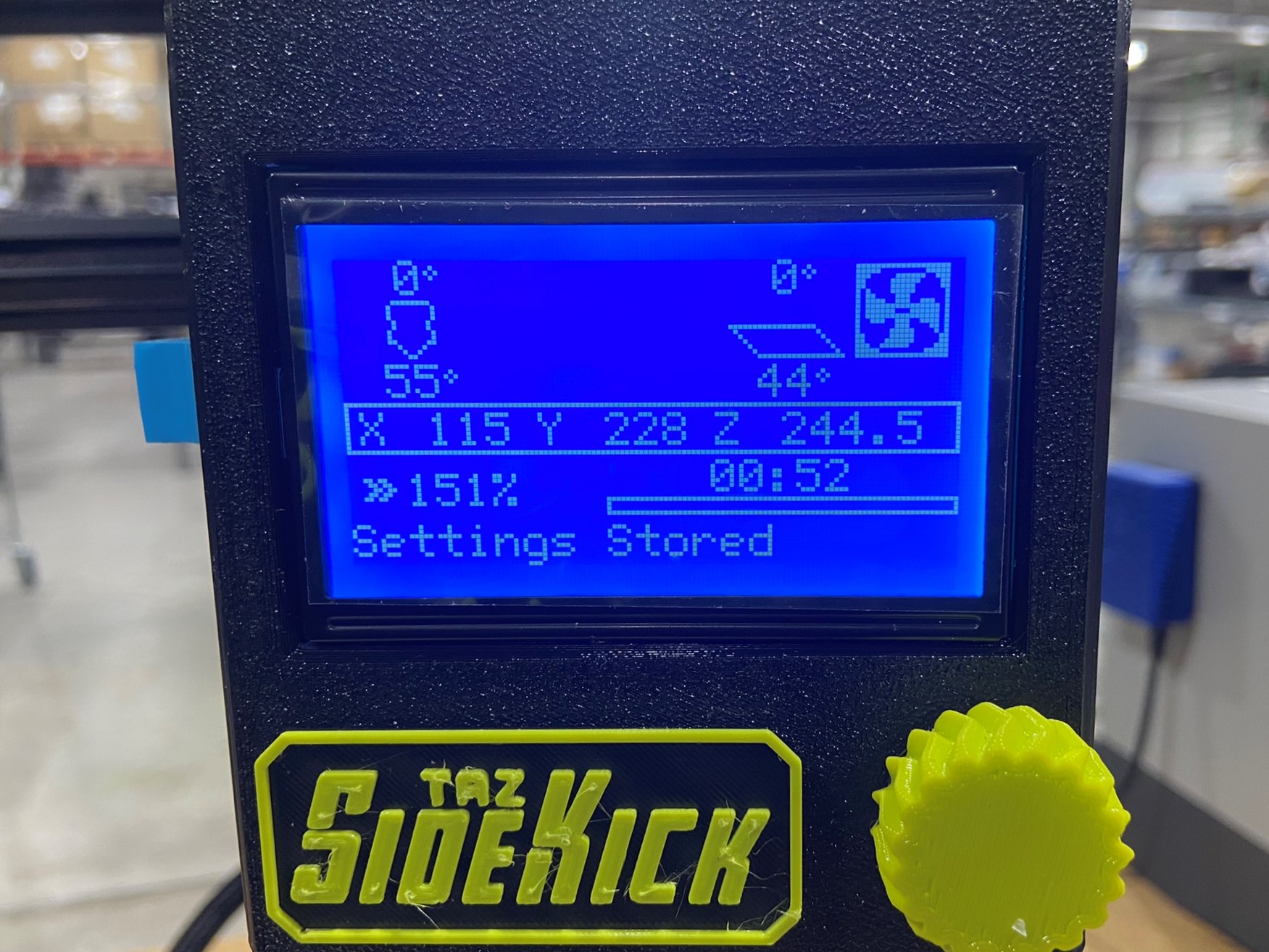
Plug in the printer, and turn it on with the red switch in the front right corner. Once the printer is turned on the LCD should show a bright blue screen.
Note: If the LCD is a dark blue color the LCD wires are connected to the wrong ports in either the control box or the LCD box.
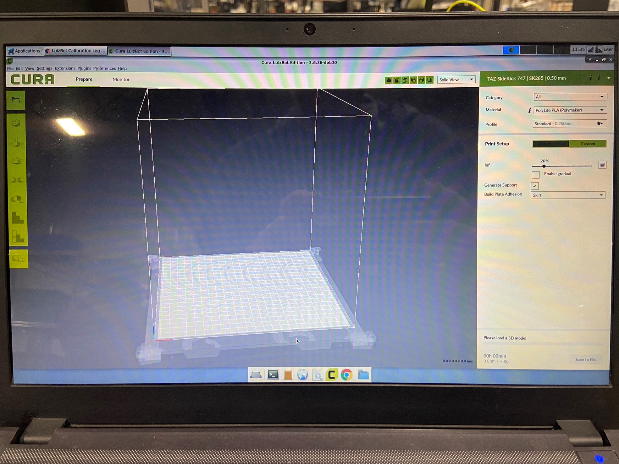
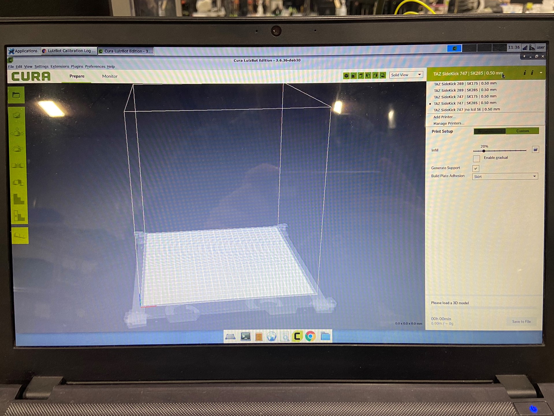
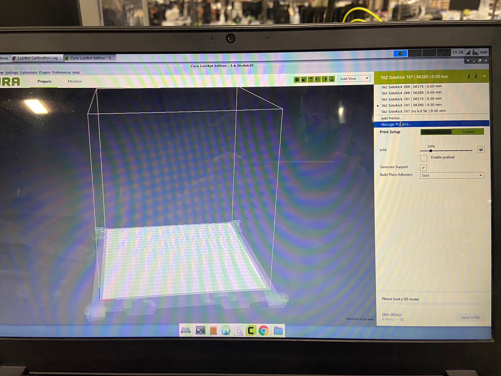
Take the cord that's connected to the calibration laptop and plug it into the top of the control box. Once the cord is connected open CURA and click on the green banner that shows the previous printer, tool head, and nozzle size. Once clicked it will show a drop down menu and click on MANAGE PRINTERS...
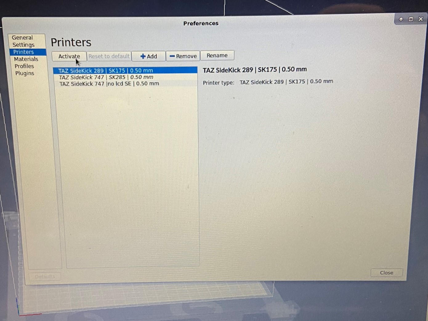
In the Manage Printers window you will see a list of SideKick printer. When selecting a printer the most important detail is selecting the right size, the tool head can be changed on the LCD once the firmware is downloaded to the printer.
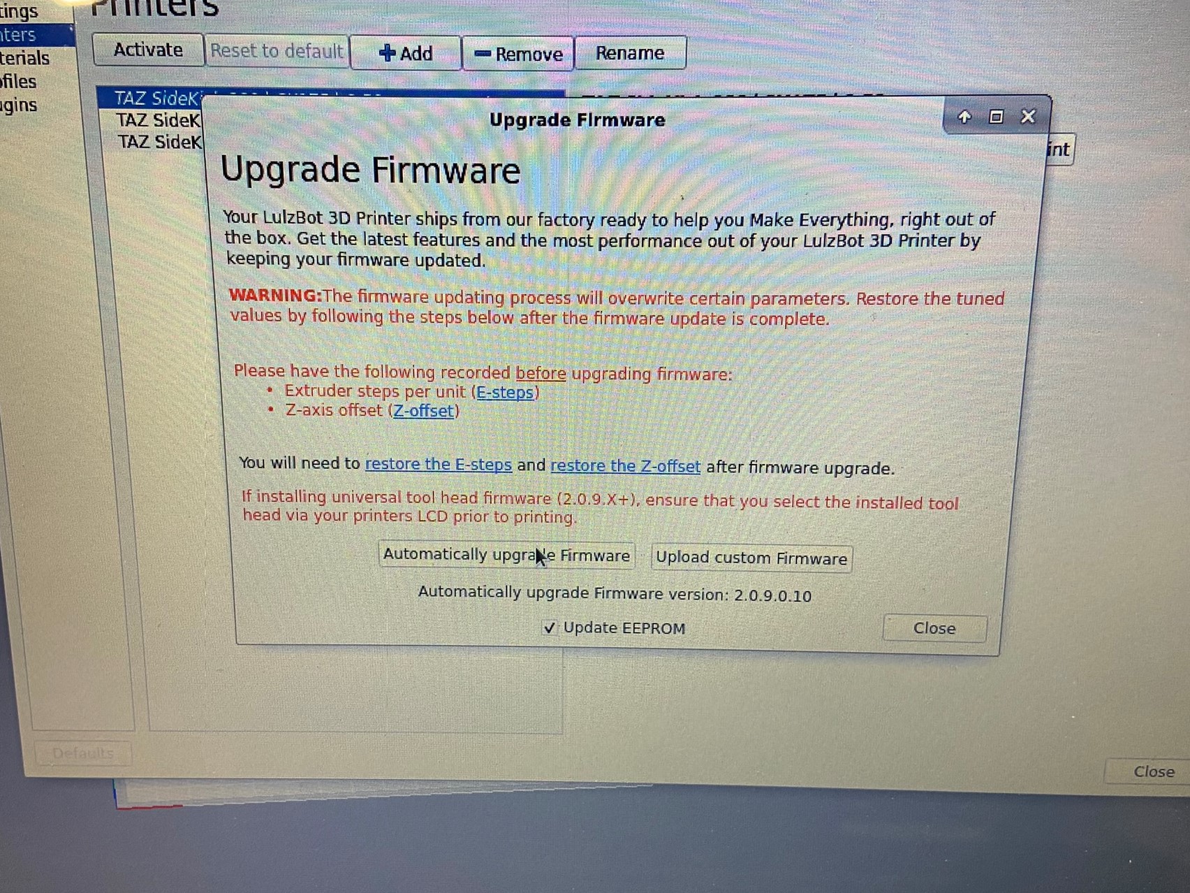
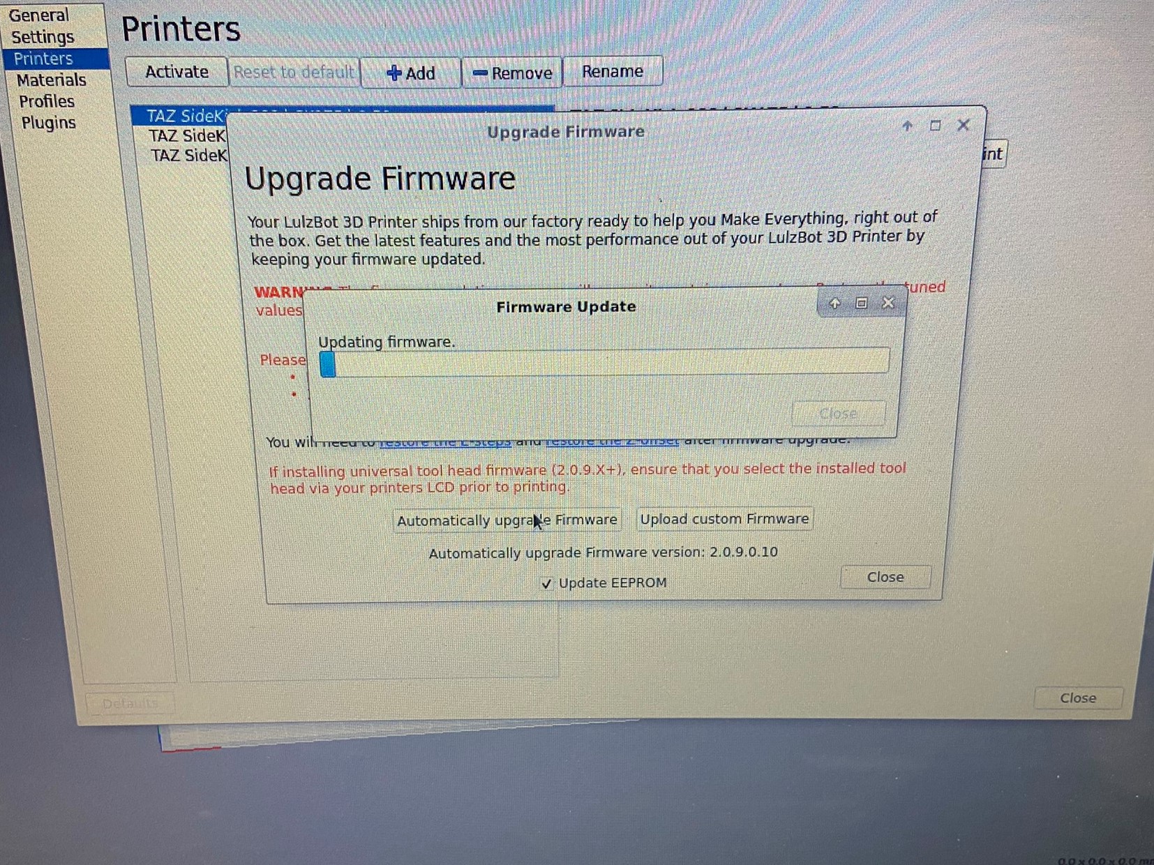
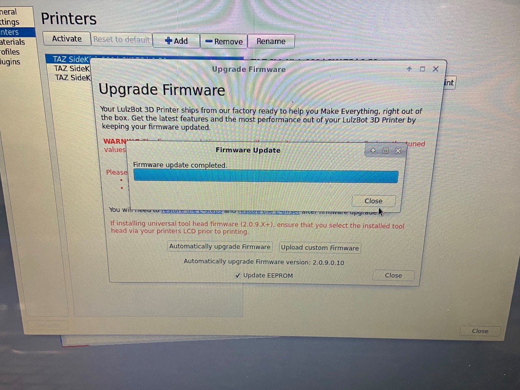
Once the printer is selected click on the ACTIVATE button to confirm your selection. Once the printer is activated click on the UPGRADE FIRMWARE button and the Upgrade Firmware window will open. Select AUTOMATICALLY UPGRADE FIRMWARE to update the printer with the newest firmware.
Once the process starts you will see a progress bar, if you get a error message that says "Firmware update failed due to a communication error" click CLOSE and wait a minute then try again. Normally this is caused because the printer is still connecting to the laptop and isn't ready for the update, if the error message shows up again set printer aside and notify the line lead.


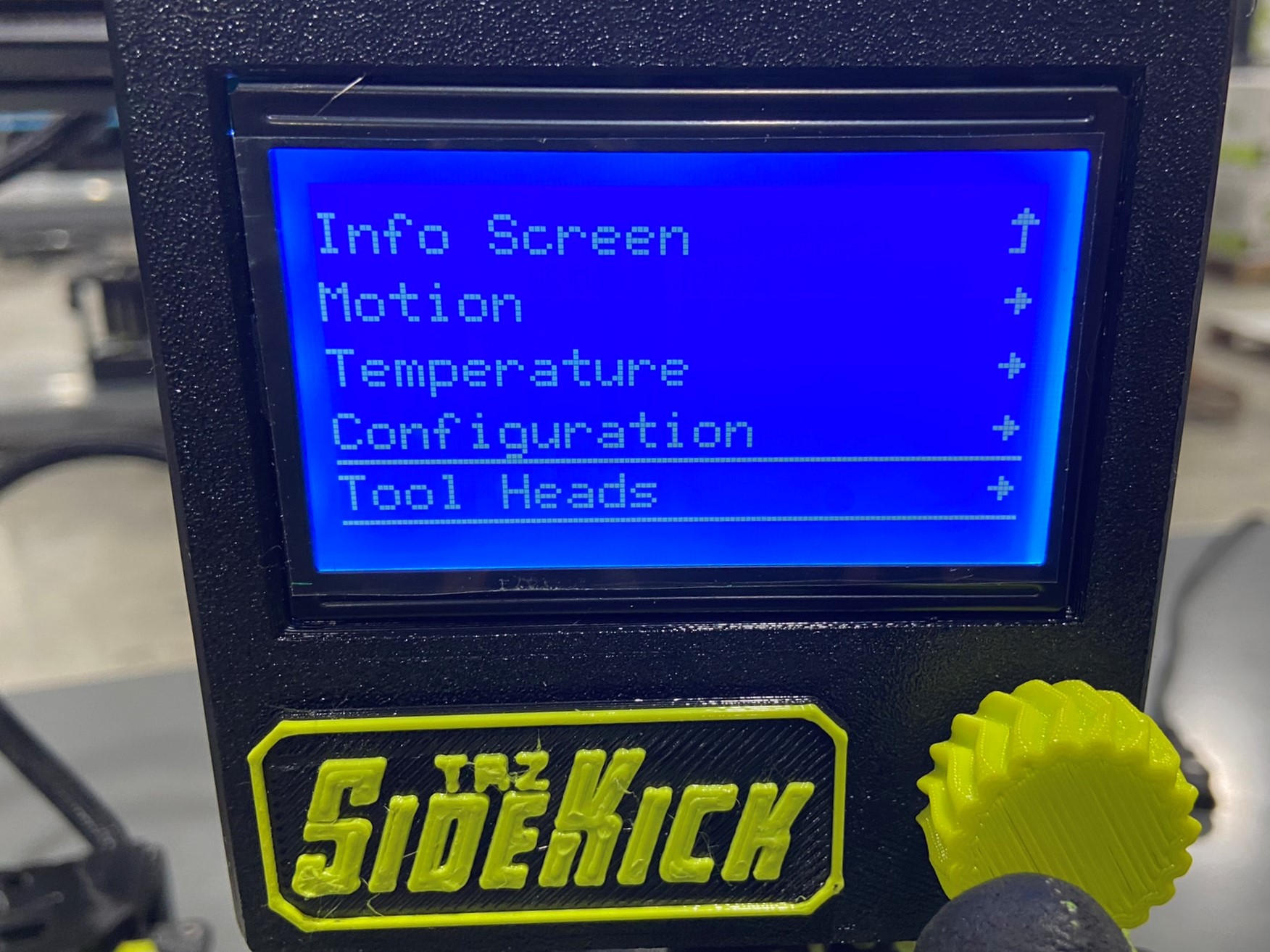
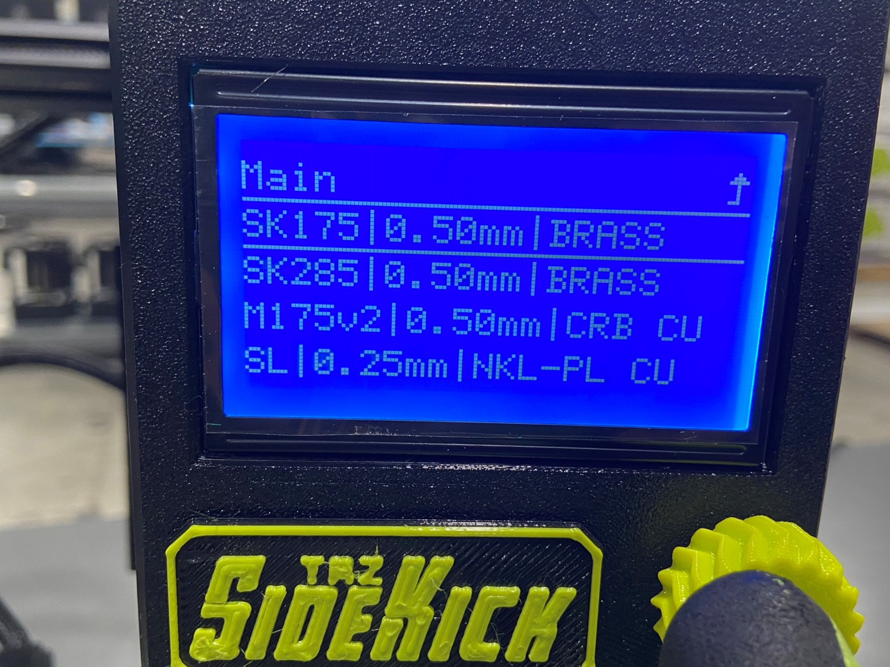
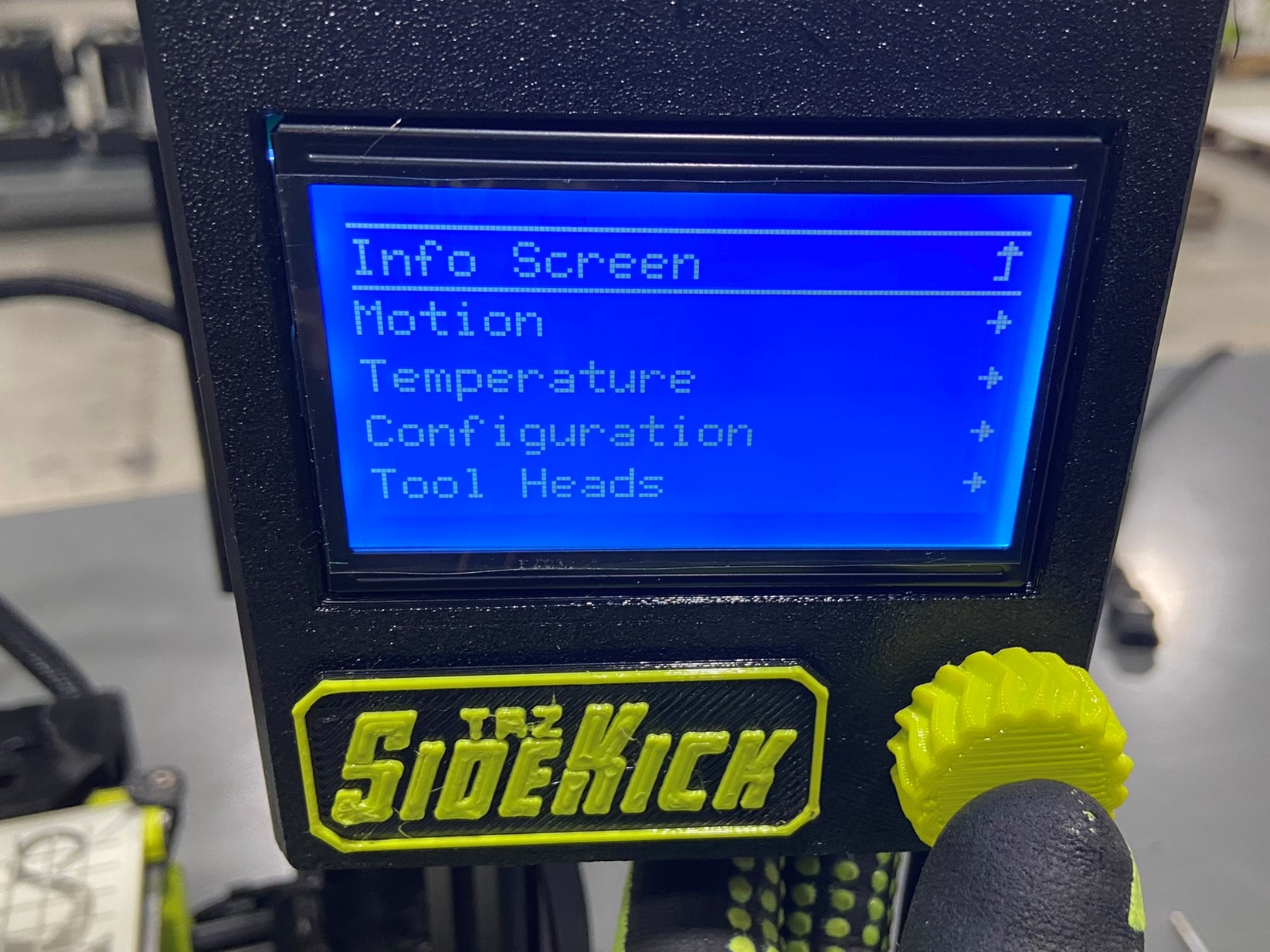
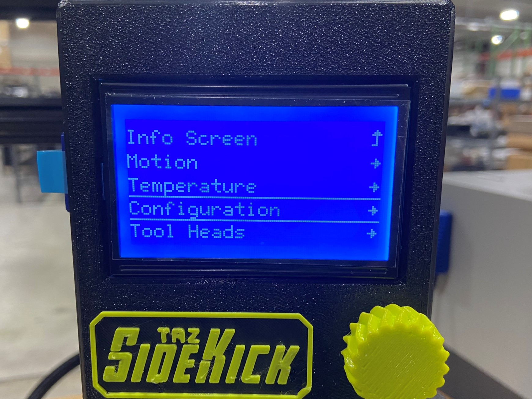
Press the Flexy knob on the LCD screen to open the menu, once the menu is open select the TOOL HEADS option. This will open a page that shows all LulzBot tool heads, if the tool head you are using and select it. The LCD should return to the Info Screen and you should see the tool head you selected on the bottom of the screen.
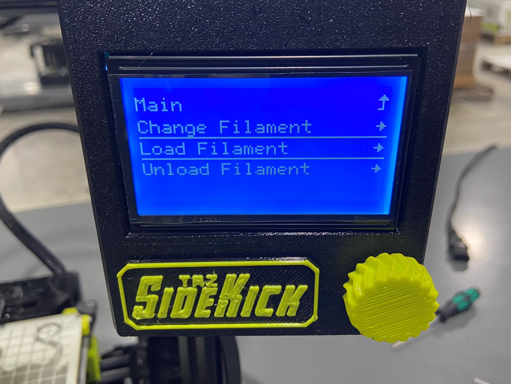
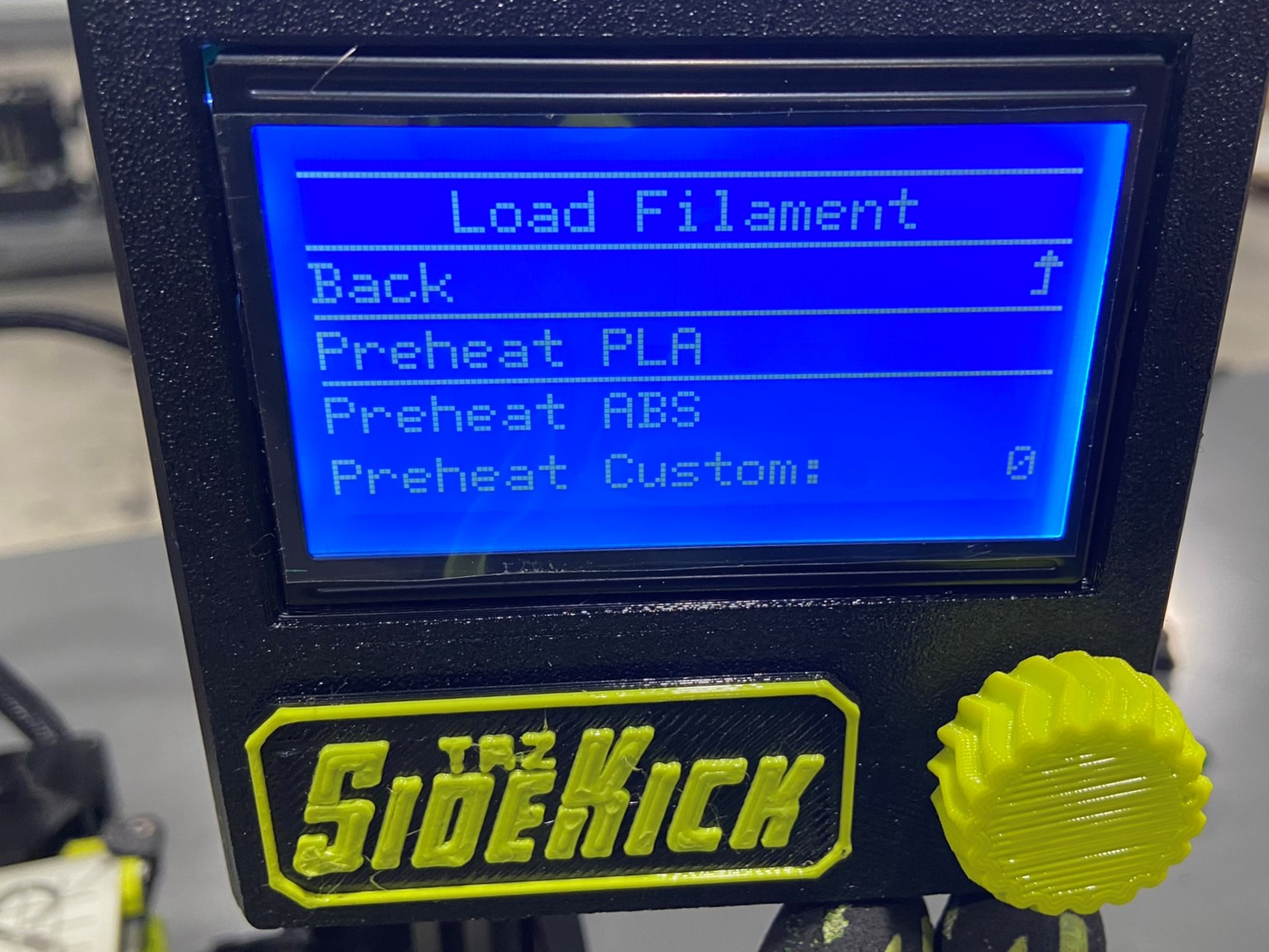
Once the tool head is saved to the printer, go back to the menu and select the CHANGE FILAMENT option. There will be three options on this screen, Change Filament, Load Filament, or Unload Filament. If the tool head you are using has a little segment of filament inside of it yet select CHANGE FILAMENT, if the tool head doesn't have any leftover filament you can select the LOAD FILAMENT option.
Change Filament will run the unload and load options.
After selecting either Change or Load Filament you should see a menu with Preheat options, you can then select PREHEAT PLA and then wait for the tool head to reach 200 degrees.
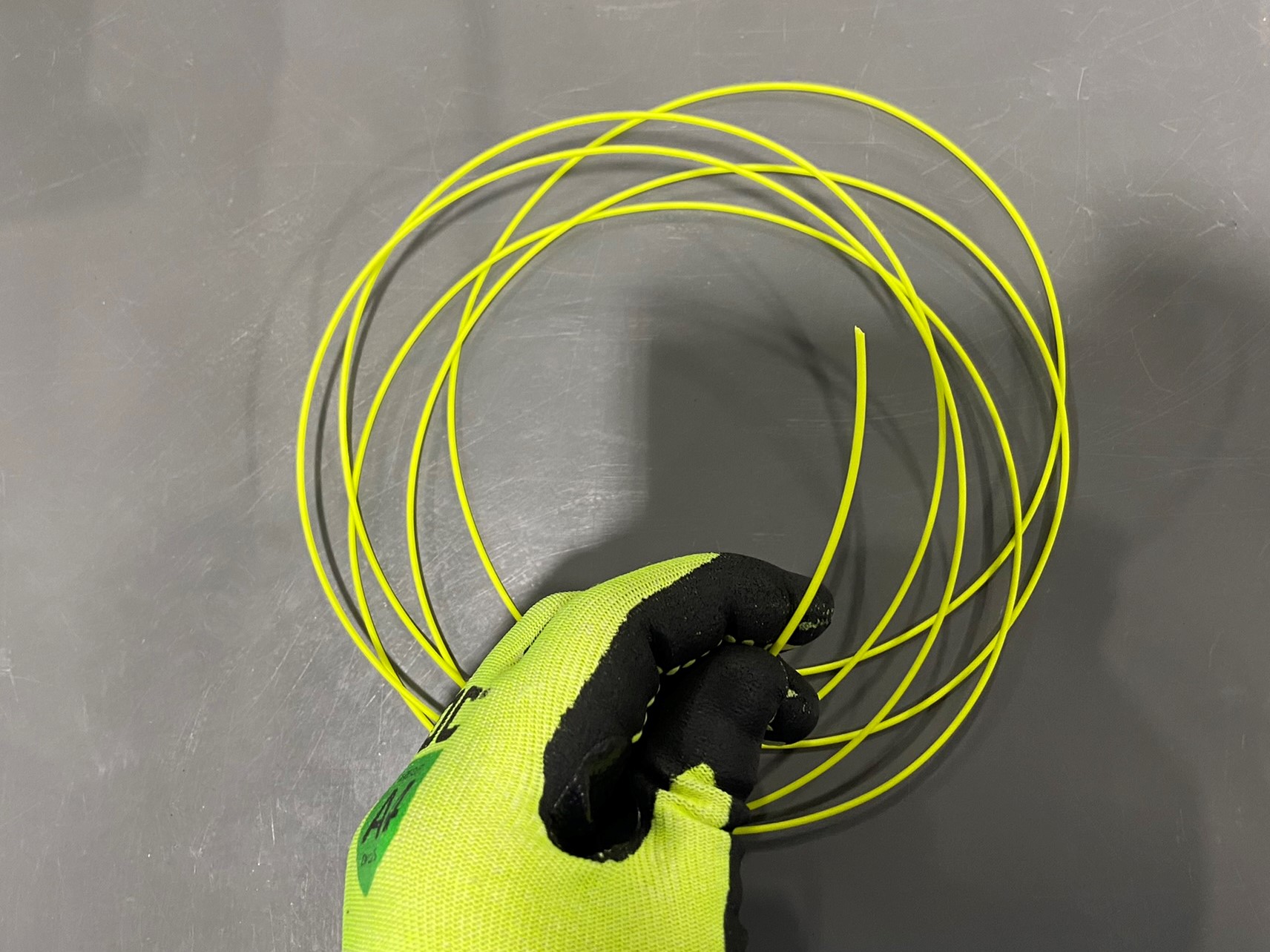
While the tool head is heating up, prepare the test print filament. If you are using an SE or SK285 tool head unwrap about 8 ft of 2.85 filament and cut the section off of the roll. If you are using an SK175 unwrap about 12 ft of 1.75 filament and cut the section off of the roll.
If there are extra rolls of filament it may be easier to place the roll on the printer's spool arm and use the whole roll of filament to ensure the print has enough filament.
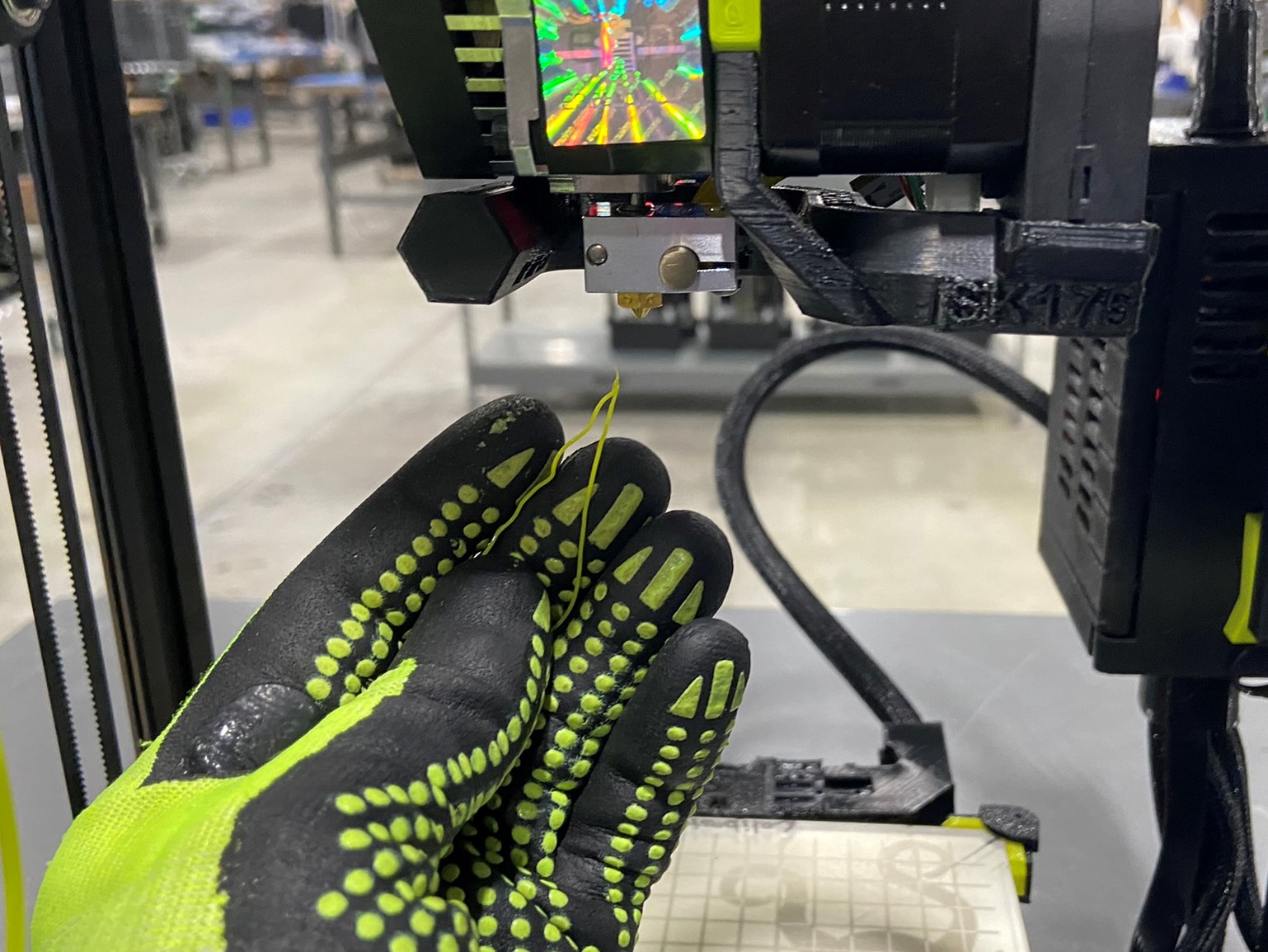
Whether you are using a segment or the spool of filament, use a cutting pliers to make a point on the end of the filament. This will help the filament load into the tool head.
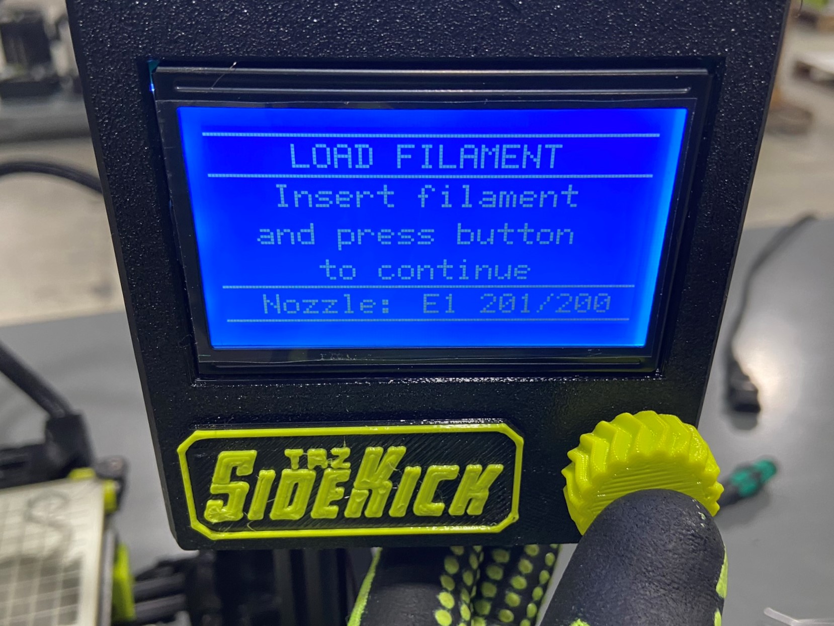
Once the tool head reaches 200 degrees the Unload or Load program will run. slide the pointed end of the filament through the hole on the black filament guide and pull the filament guide forward. Then push down on the filament until you feel the gear catch and pull the filament down. This may take a couple tries and if need remove the filament and try to straighten it.
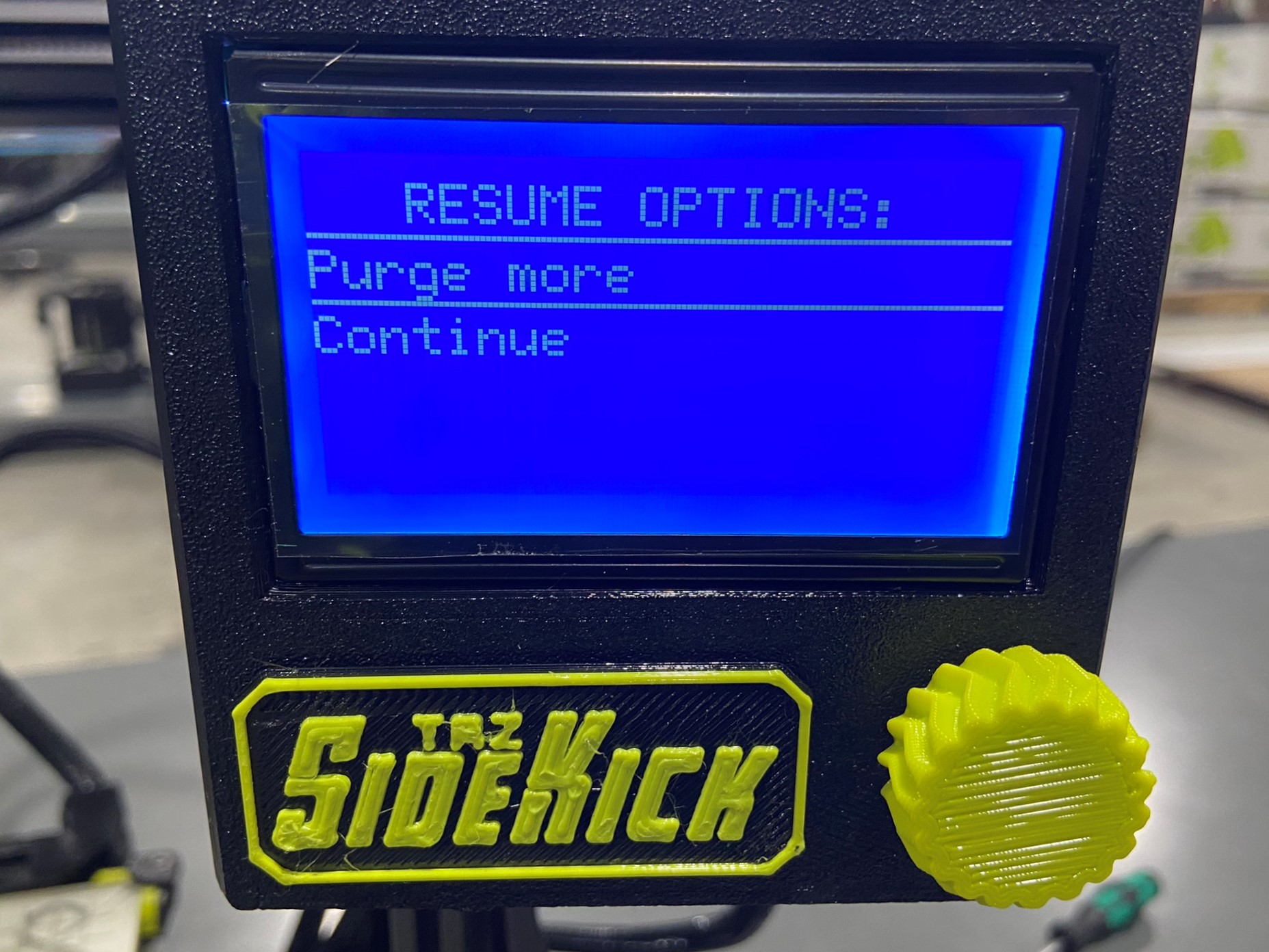
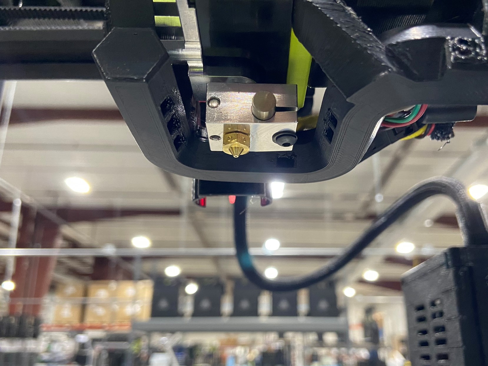
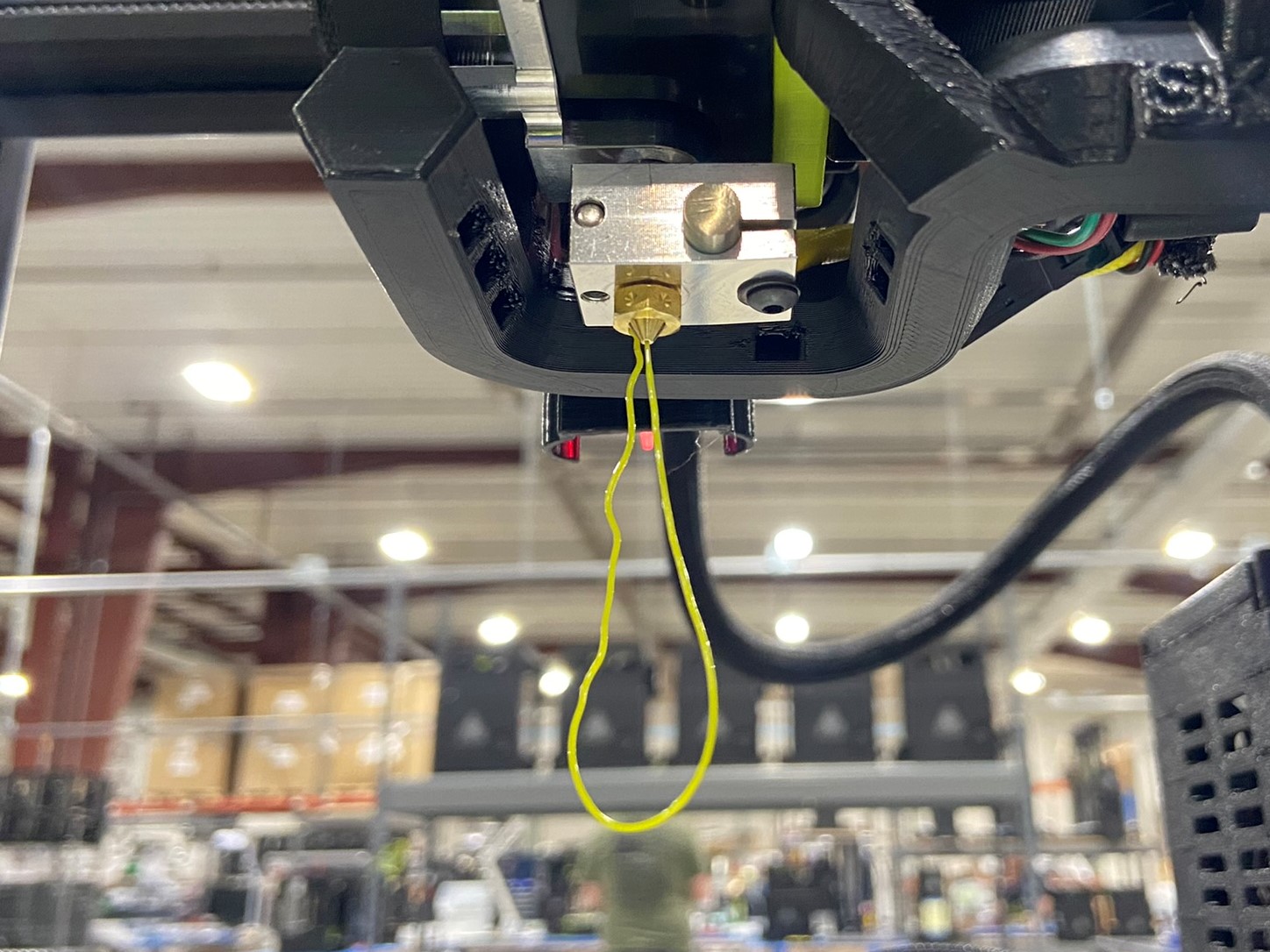
After the load program runs for a bit it will ask if you want to purge more filament or continue. Look at the nozzle on the tool head and if you see a line a filament you can press CONTINUE, but if there is no filament press PURGE MORE repeat this process until there is filament coming out of the nozzle.
If you are using one of the SE tool heads and it previously printed with a different color filament you may want to purge until the current filament is solely coming out of the nozzle.


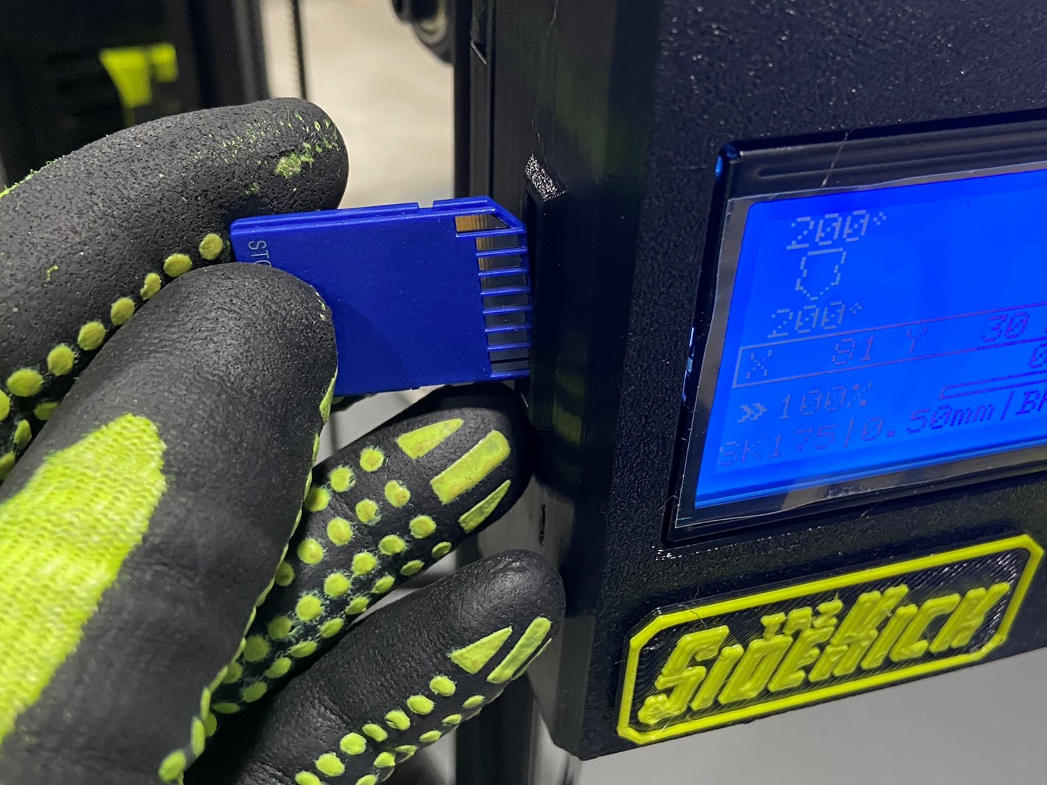
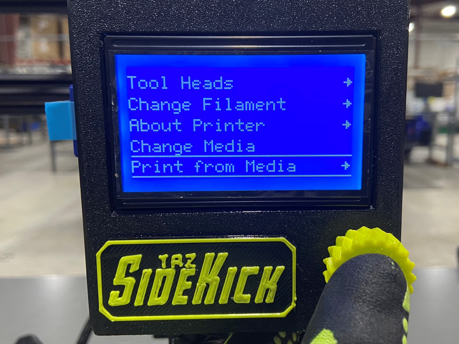
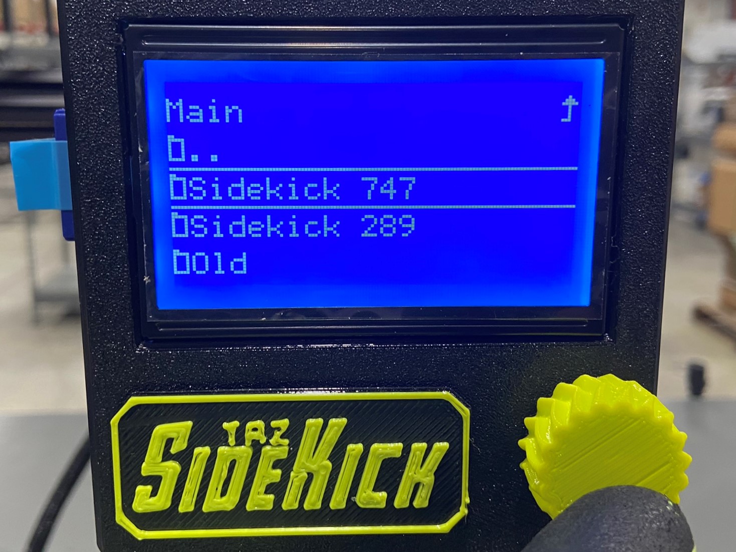
Take one of the calibration SD card and insert it in top the SD reader on the left side of the LCD box. Make sure the LCD say media inserted on the bottom side of the screen. Then press the flexy knob on the LCD screen to open the menu. Once the menu is open scroll using the knob all the way to the bottom and select PRINT FROM MEDIA.
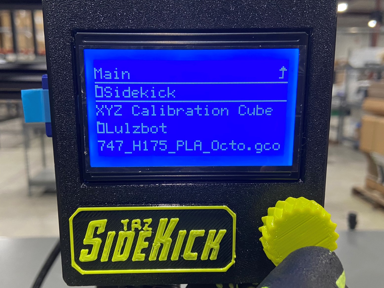
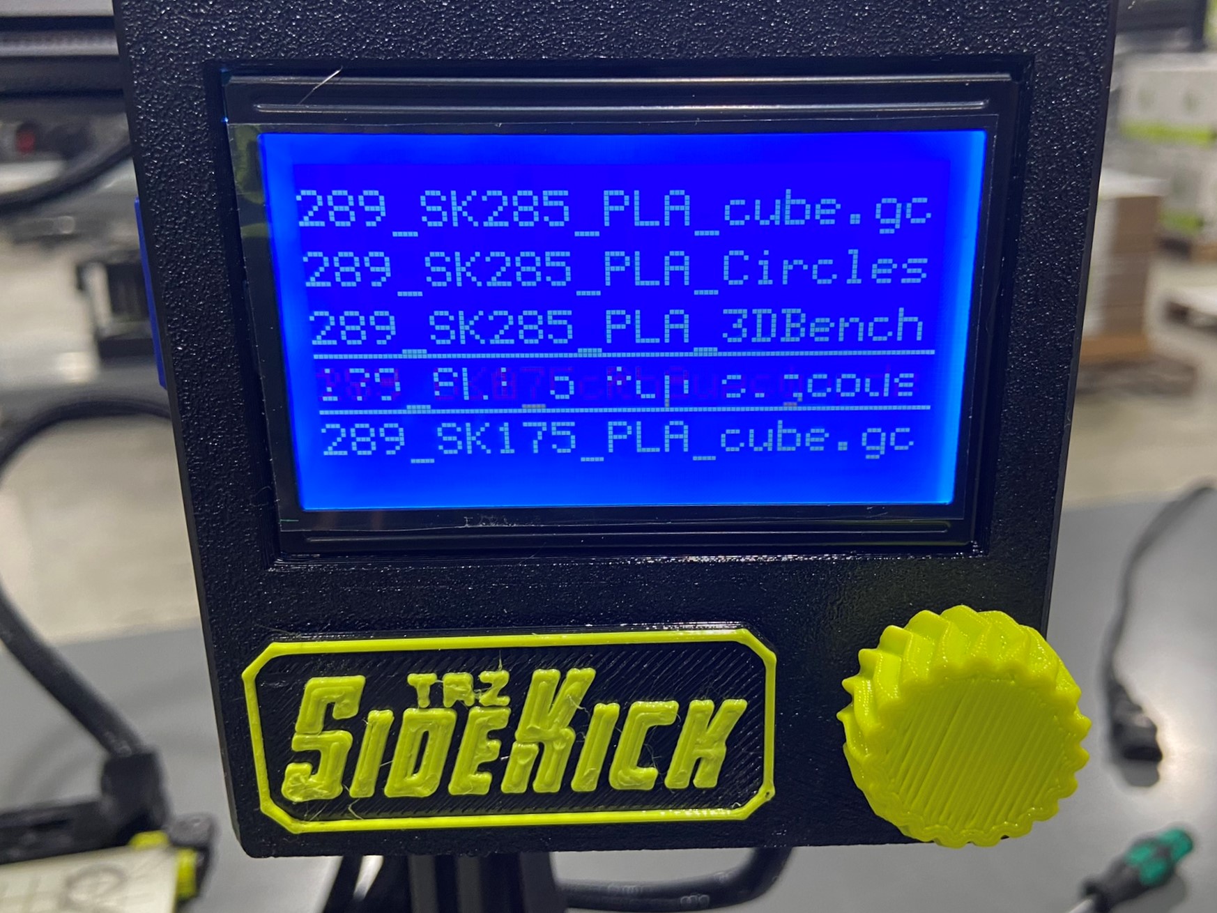
This will open all the print files that are preloaded onto the SD card. There should be a SK 289 folder along with a SK 747 folder. Once again select the correct size then scroll through the list of files until you find the print file created for the tool head you are calibrating with.
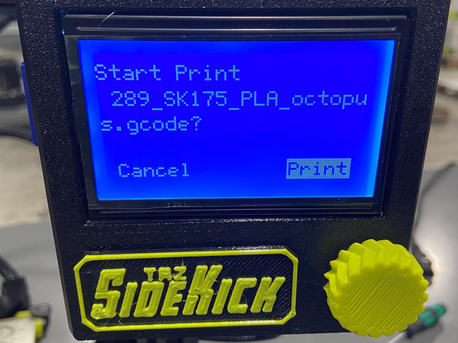
Once you find the correct file press the knob and select PRINT
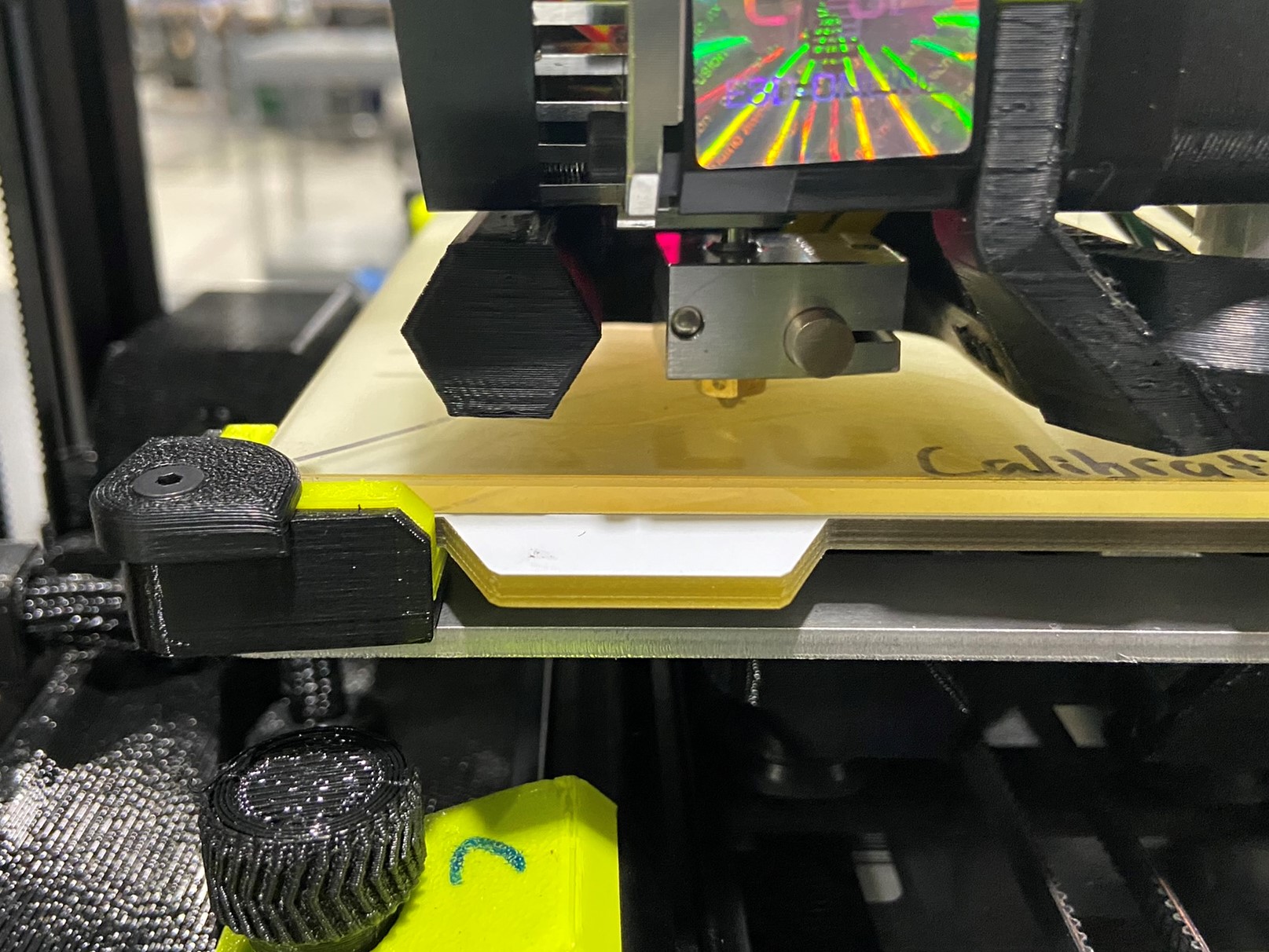
Before the printer start to print you will have to wait for the tool head and bed plate to reach the print heat settings, this may take some time.
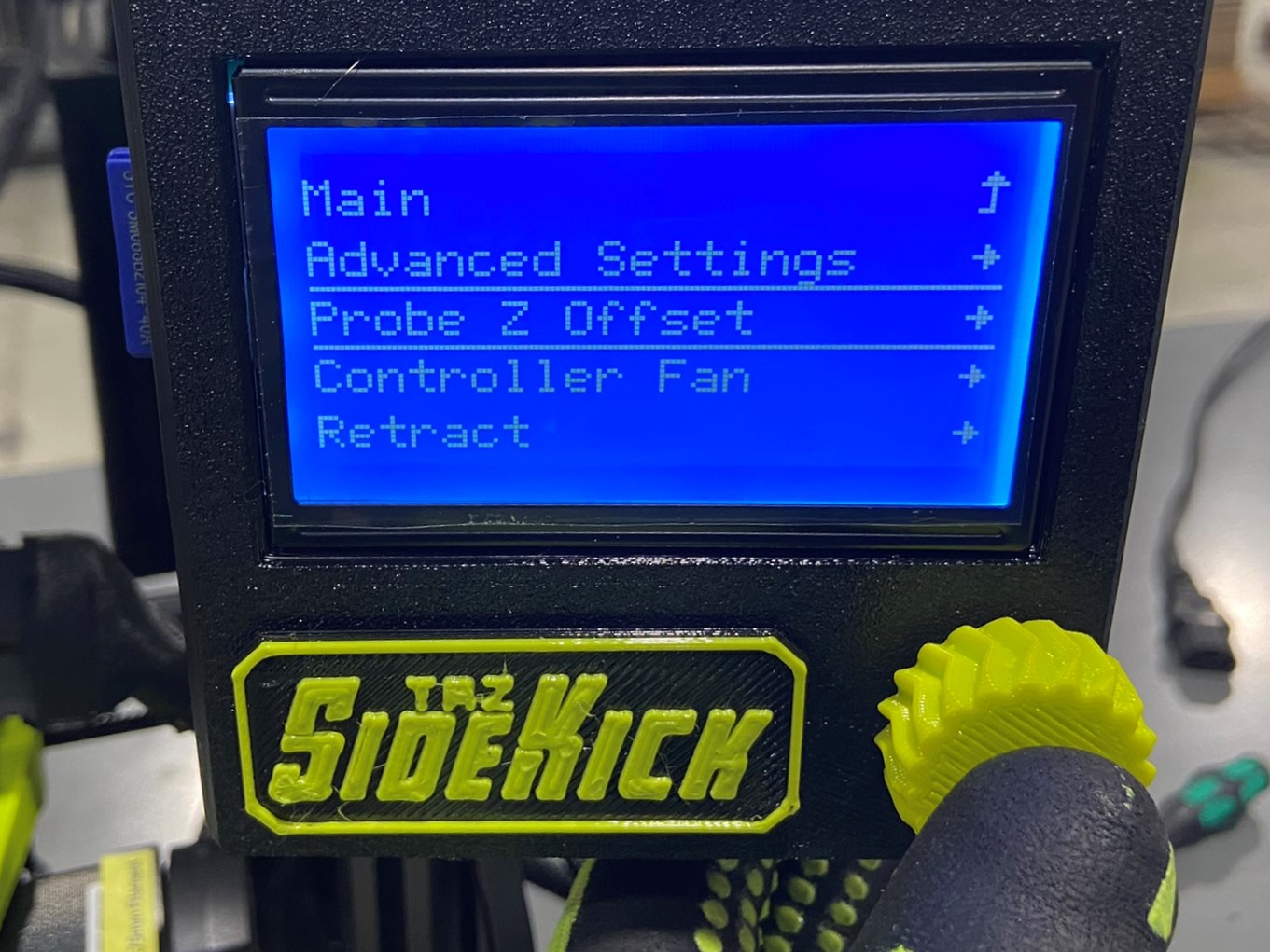
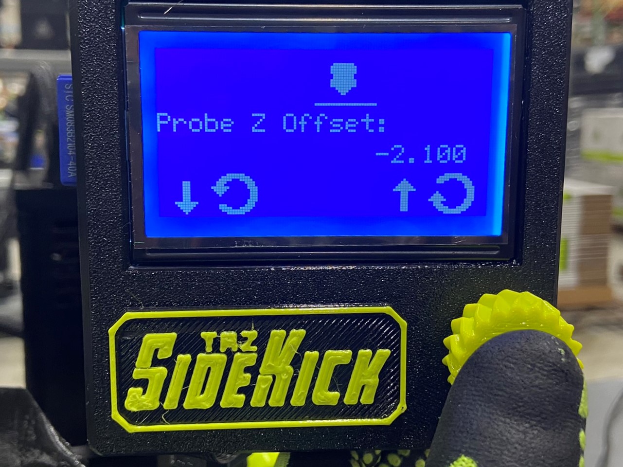
As the tool head and bed plate near the target temperatures, double click on the LCD flexy knob to open the Probe Z Offset page. This will adjust how close the nozzle is to the bed, you want a semi-squished bead. The print will first make a "skirt" around the print area, you can fine tune the Z offset during this time.
If you still need more time to adjust the offset the file will then make a circle in the front left corner.
Each printer will have a different Z offset value, but on average they are between -0.700 to -1.700
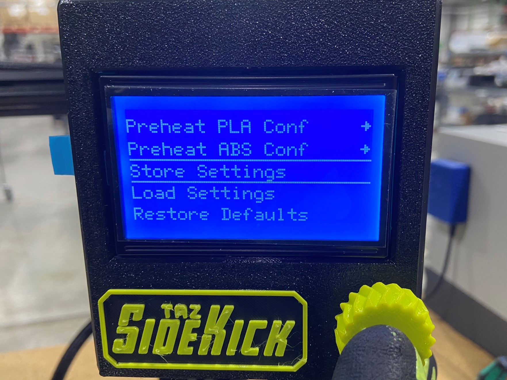
You can also access the Probe Z Offset settings by going to the printer's menu, and selecting the CONFIGURATION option. Once you are in the configuration options find the PROBE Z OFFSET option and select it.


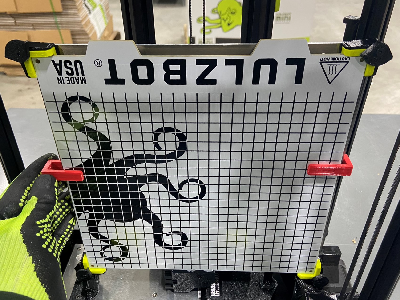
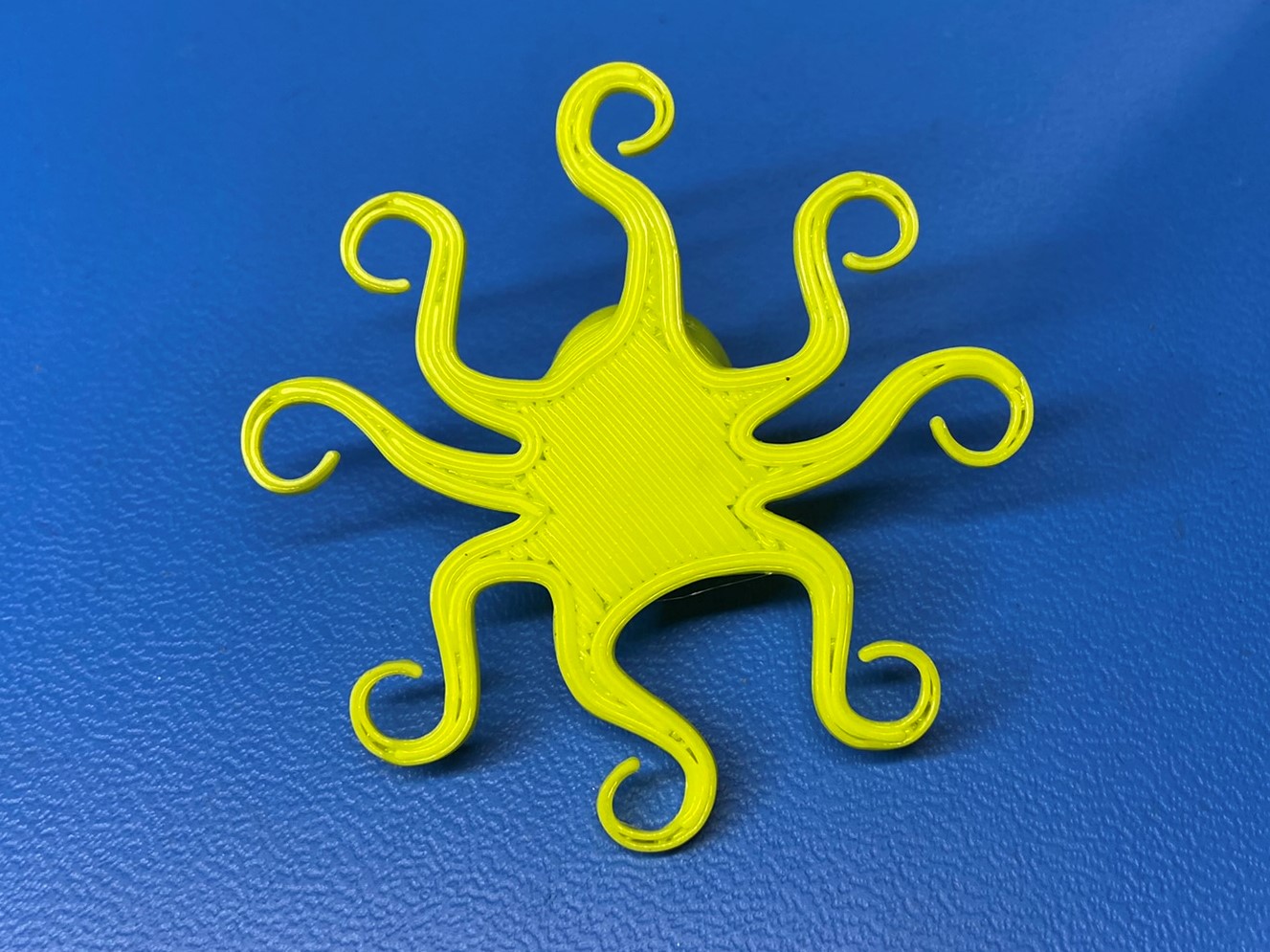
Once the test print is finished check the bottom of the print, if you can see very distinct lines that seem to have gaps between them the Z offset is too high and need to lowered.
If the bottom of the print is complexly flat and its hard to identify where each line is then the Z offset is too low and needs to be raised.
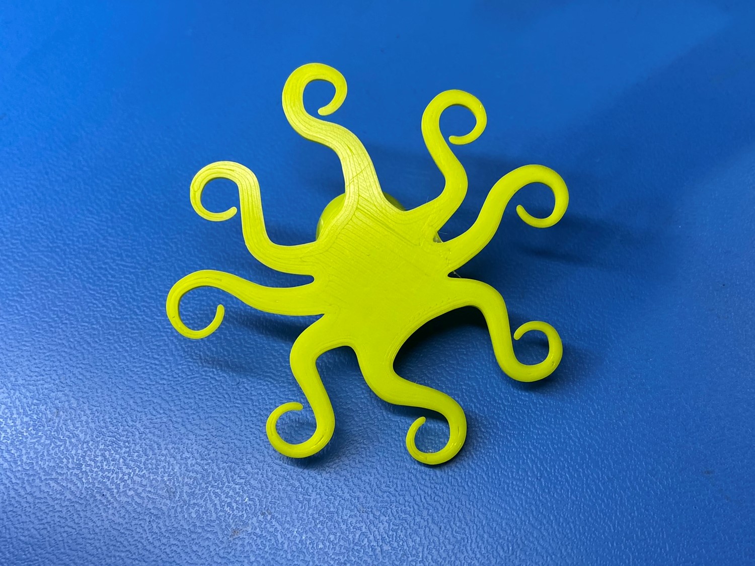
If you can see somewhat distinct lines that have very small gaps that you can feel when you run your finger over the back, then the Z offset is good and can be saved to the printer.
The customer will have to fine-tune the Z offset once they setup their new printer so it doesn't have to be perfect but try to save a good Z offset to the printer.


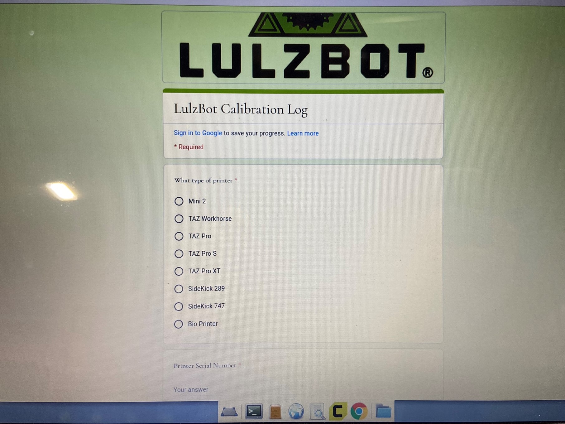
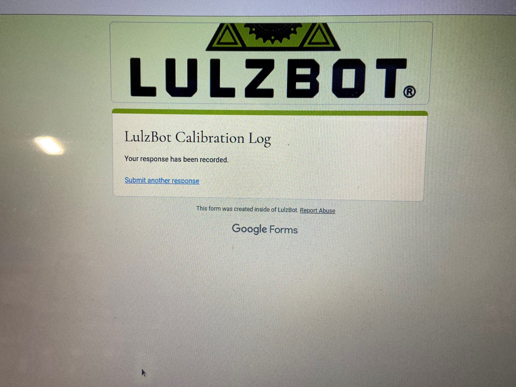
Once the test print is removed from the printer and it passes inspection, open the Google Form that's titled LulzBot Calibration Log.
Once the form is open, record all the measurements or notes you took while calibrating the printer. If there was something changed on the printer try to be specific when you document it.
When all the entries are filled out submit the form.
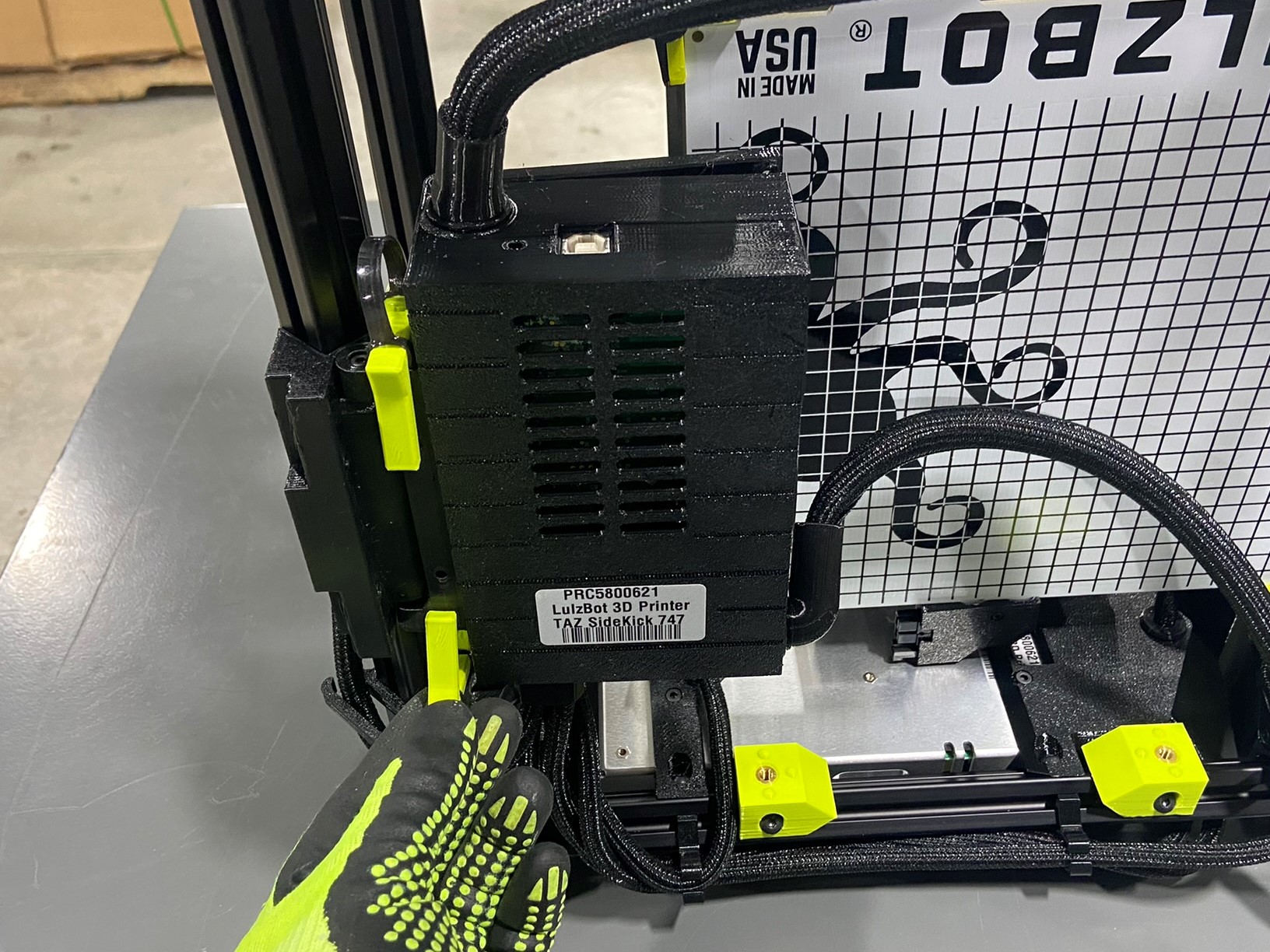
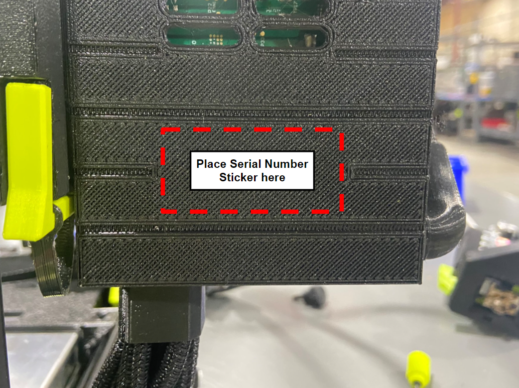
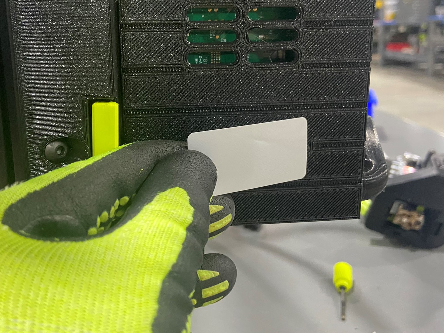
Before placing the serial number sticker, check the backside of the control box and make sure the area is clean and that the control box doesn't have any cosmetic issues.
Then find the sticker that has the same serial number as the power supply and place it on the back of the control box.
Remove the calibration glass or magnetic bed plate from the Y axis, while keeping the heated plate inside the bed corners. Then remove the four thumb screw that are holding the Y axis in place and unplug the Y Motor harness and bed harness.
Once the Y axis is completely removed from the printer rotate it so that the heat plate is facing the control box and that Y idler is pointed towards the ceiling. Then slide it through the printer and then through the Z upper and hook the flexy bumpers into the Z upper extrusion.
Once the Y axis is hanging inside the printer align the left hole on the Y motor mount with the left frame mount and use a new Y axis thumb screw to secure the Y axis in the shipping position.
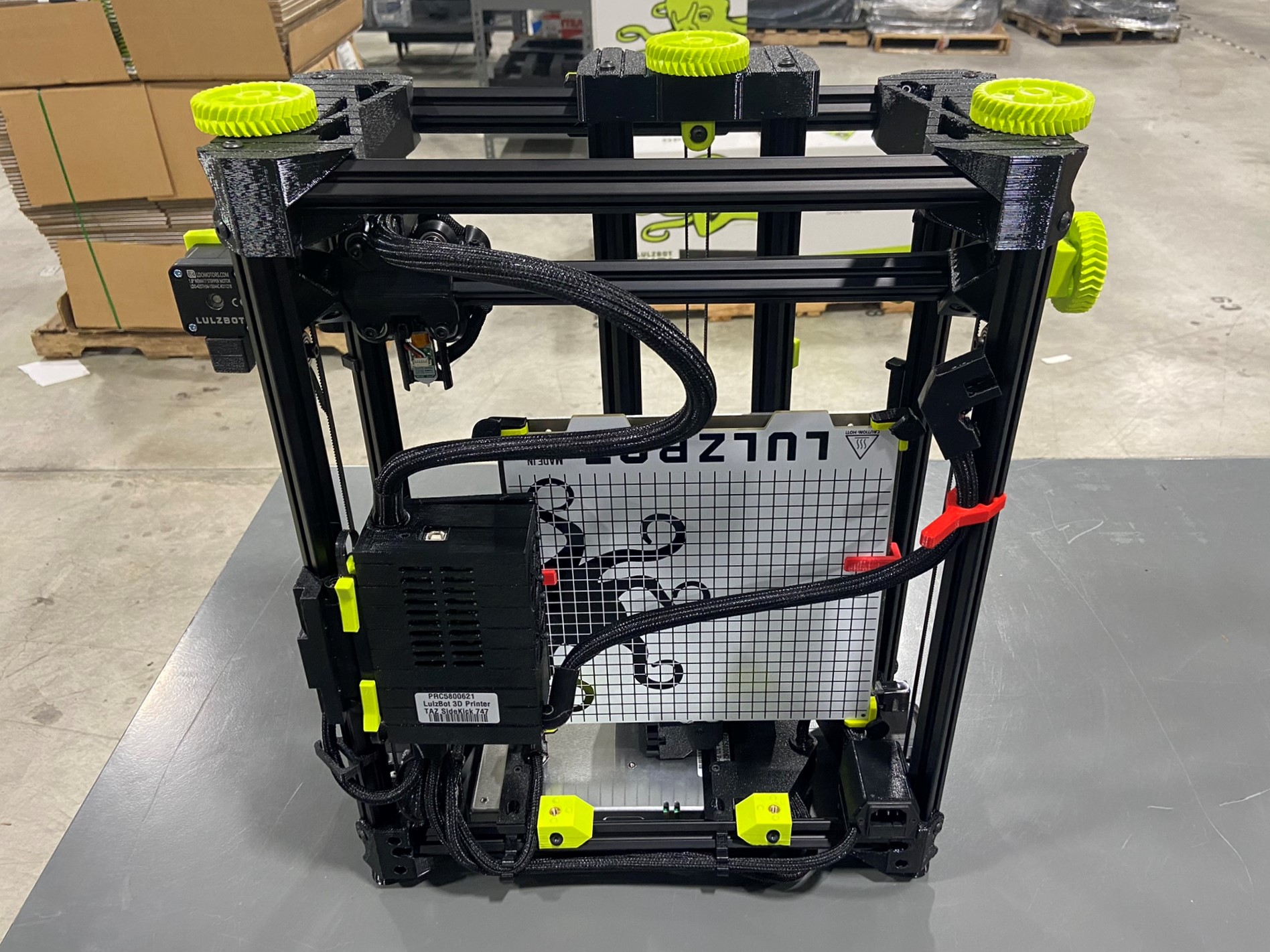
Turn the printer around so that you are looking at the backside and take two control box clips that were printed with the test print and place them on the side of the Y axis to secure the heated plate to the octoplate.
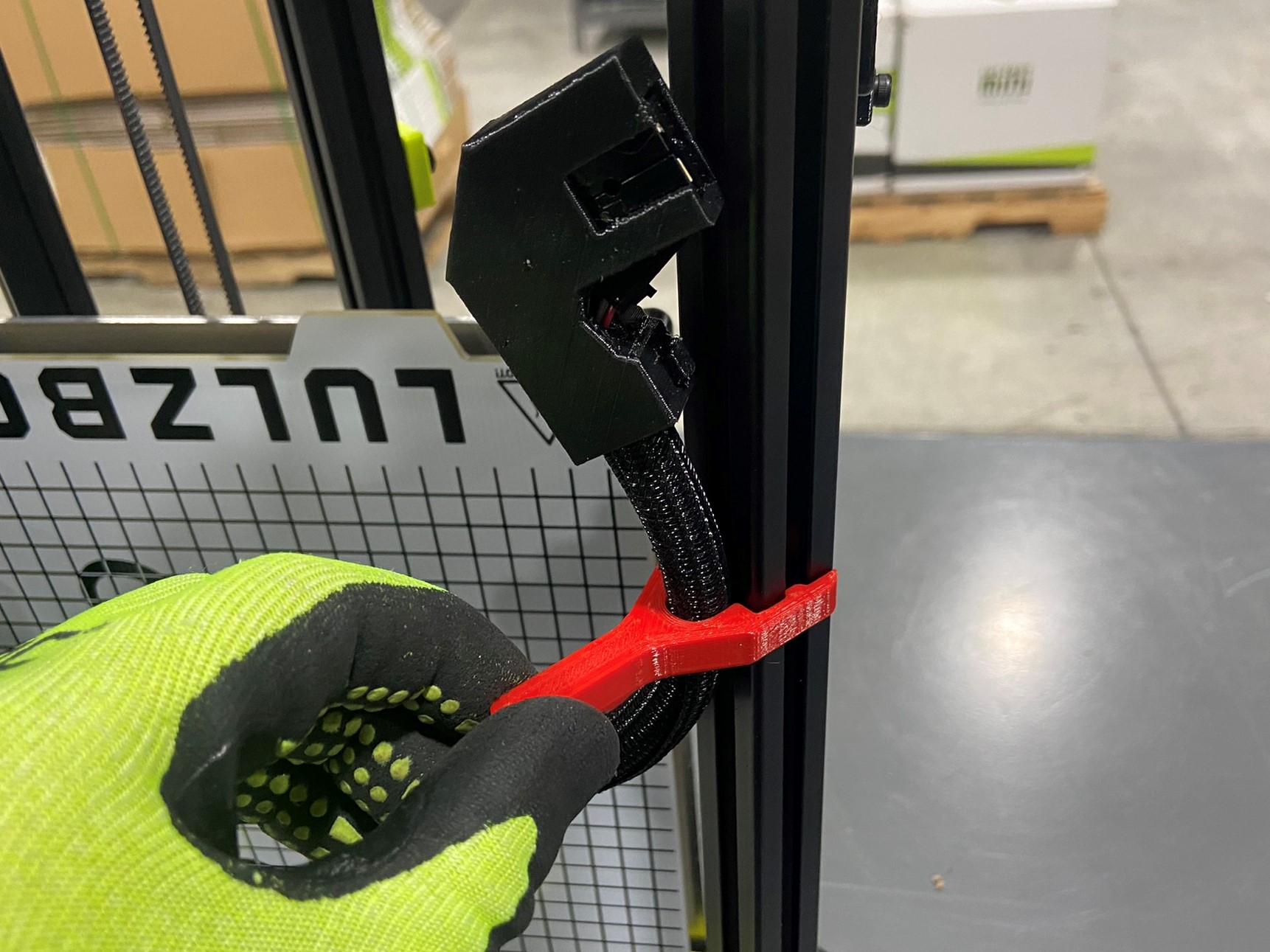
Then remove the two control box clips and rotate the control box to the shipping position and replace the control box clips. Then take the harness clip and clip the bed harness to the rear left extrusion.