Open HardwareAssembly Instructions
Guides for installation and assembly of the LulzBot line of products made by FAME 3D LLC.
Guides for installation and assembly of the LulzBot line of products made by FAME 3D LLC.
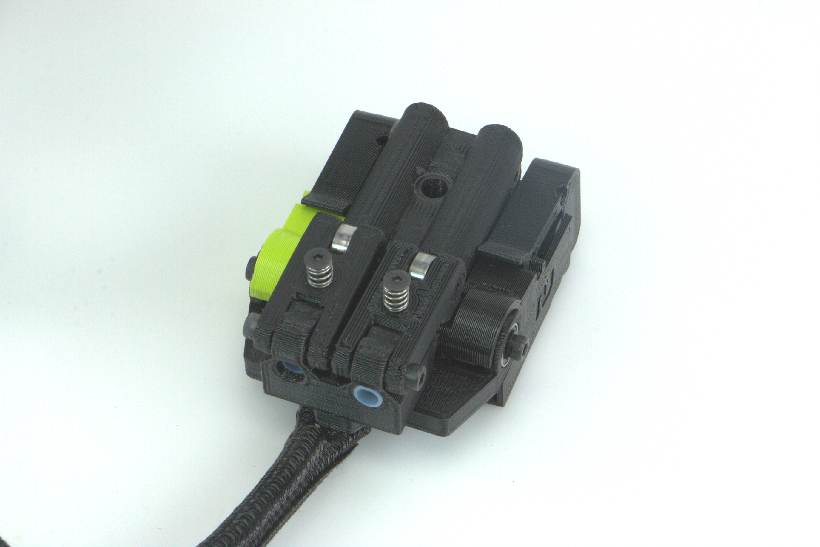
The TAZ Pro Jetpack: Jam & Runout Sensor Kit is a direct upgrade to the standard runout sensor installed on the TAZ Pro 3D printers. It allows for better ease of filament feeding as well as simple tension adjustment.
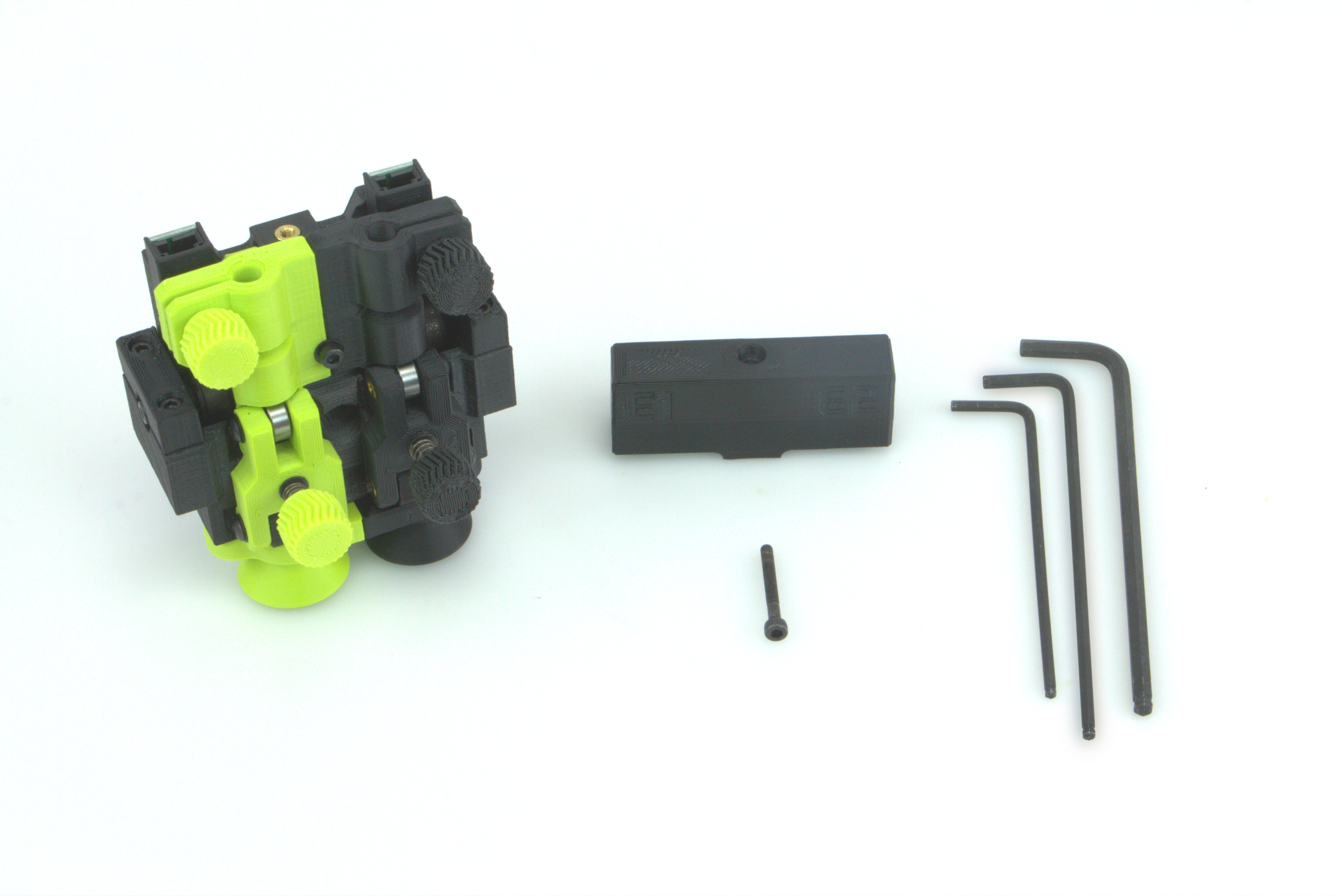
The items required for the installation of the TAZ Pro Jetpack: Jam & Runout Sensor Kit:
Before you start, power off your printer and unplug it.
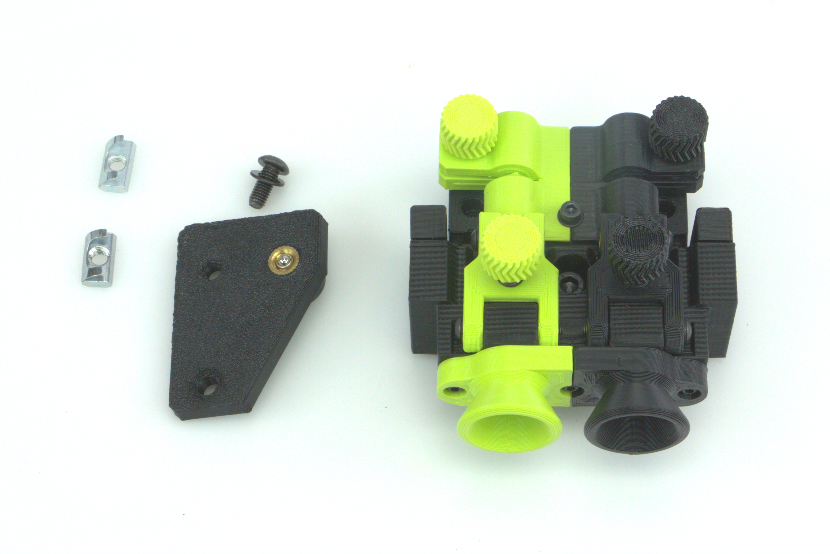
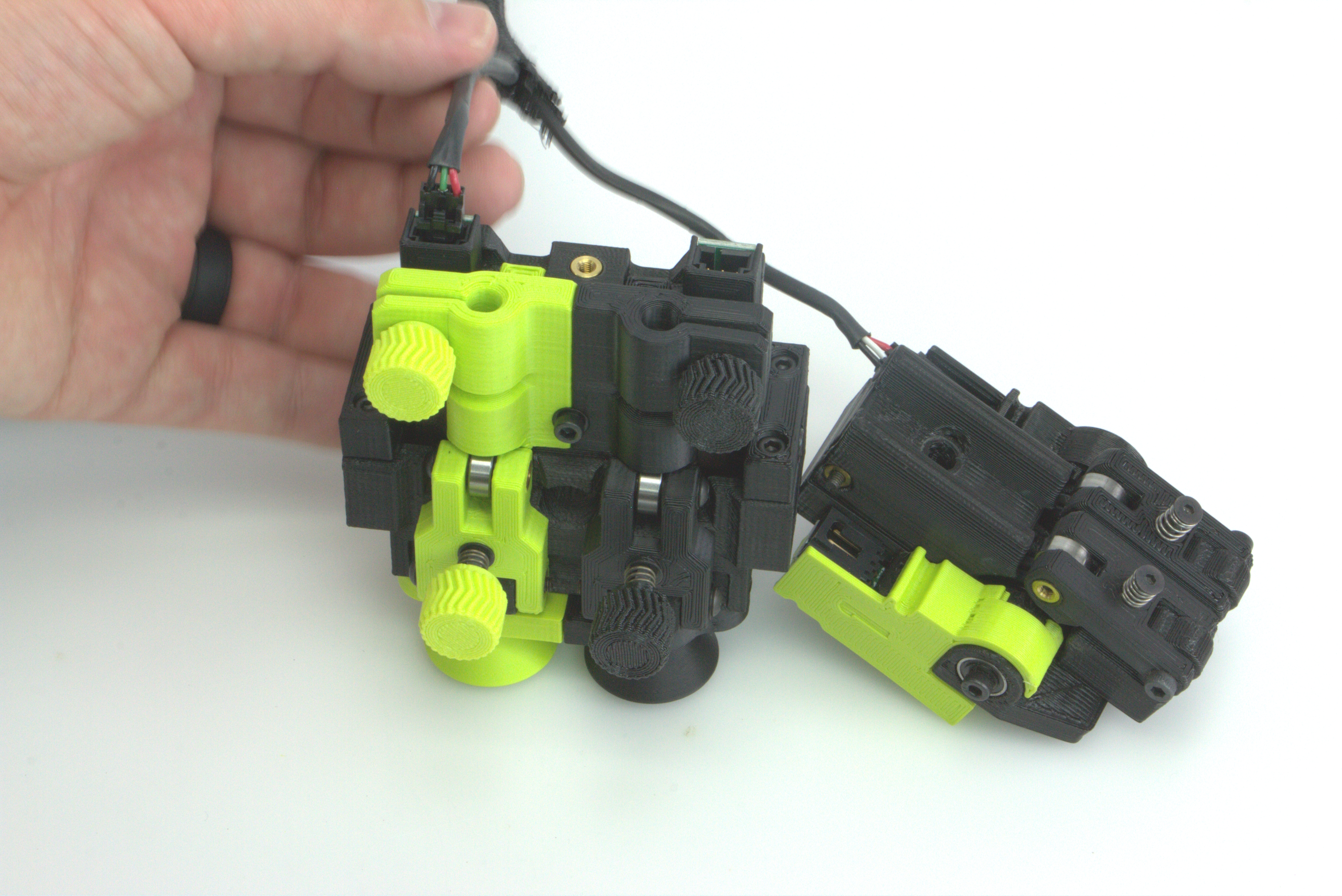
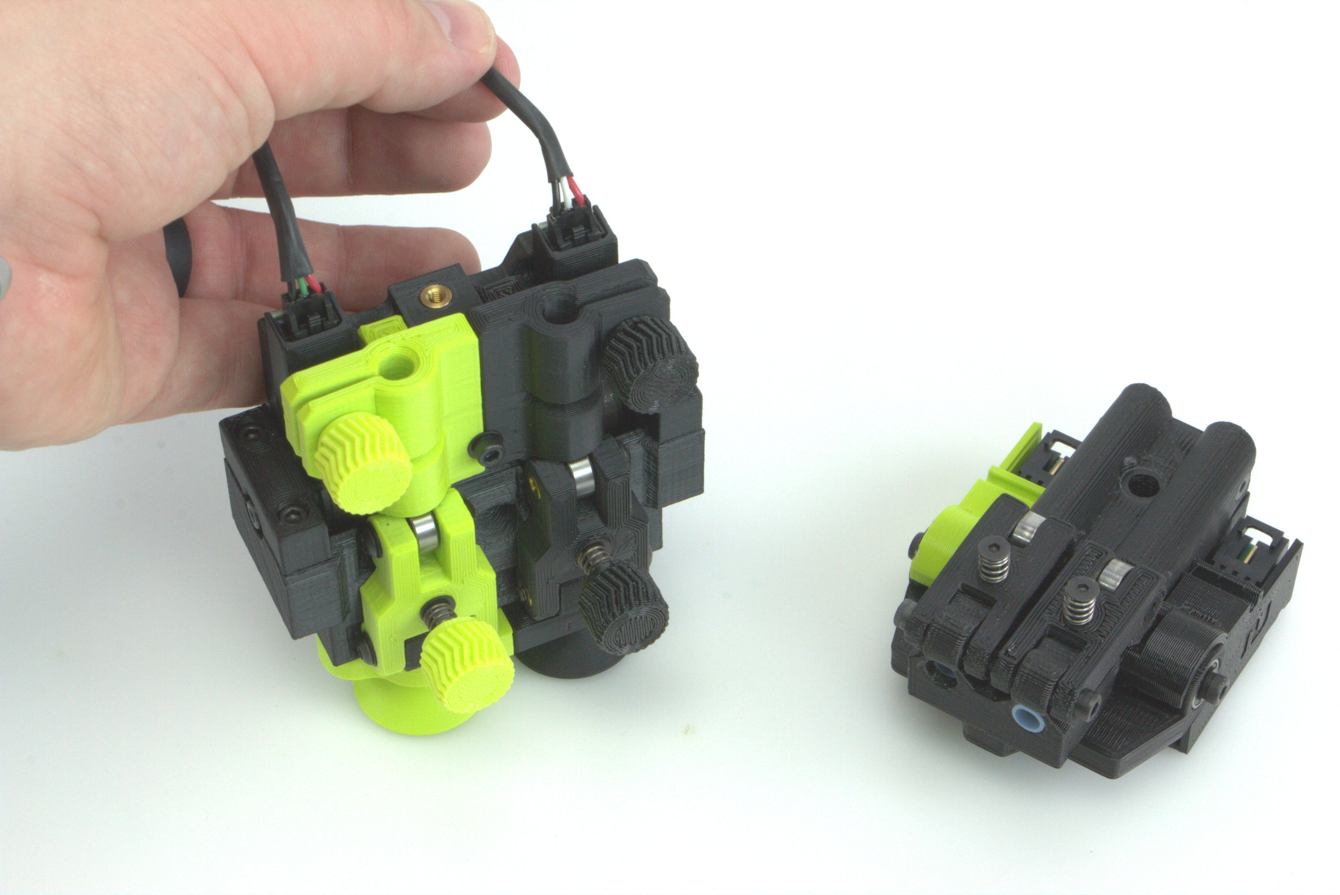
You will need to remove the two screws from the Jetpack Runout Sensor prior to installation.
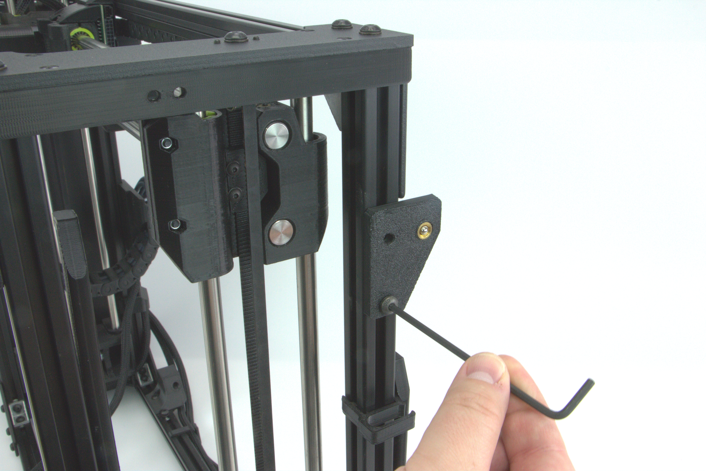
Using the 4mm hex wrench, unscrew the middle screw from the t-nut and set aside.
Using the 3mm hex wrench, unscrew the bottom screw from the t-nut and set aside.
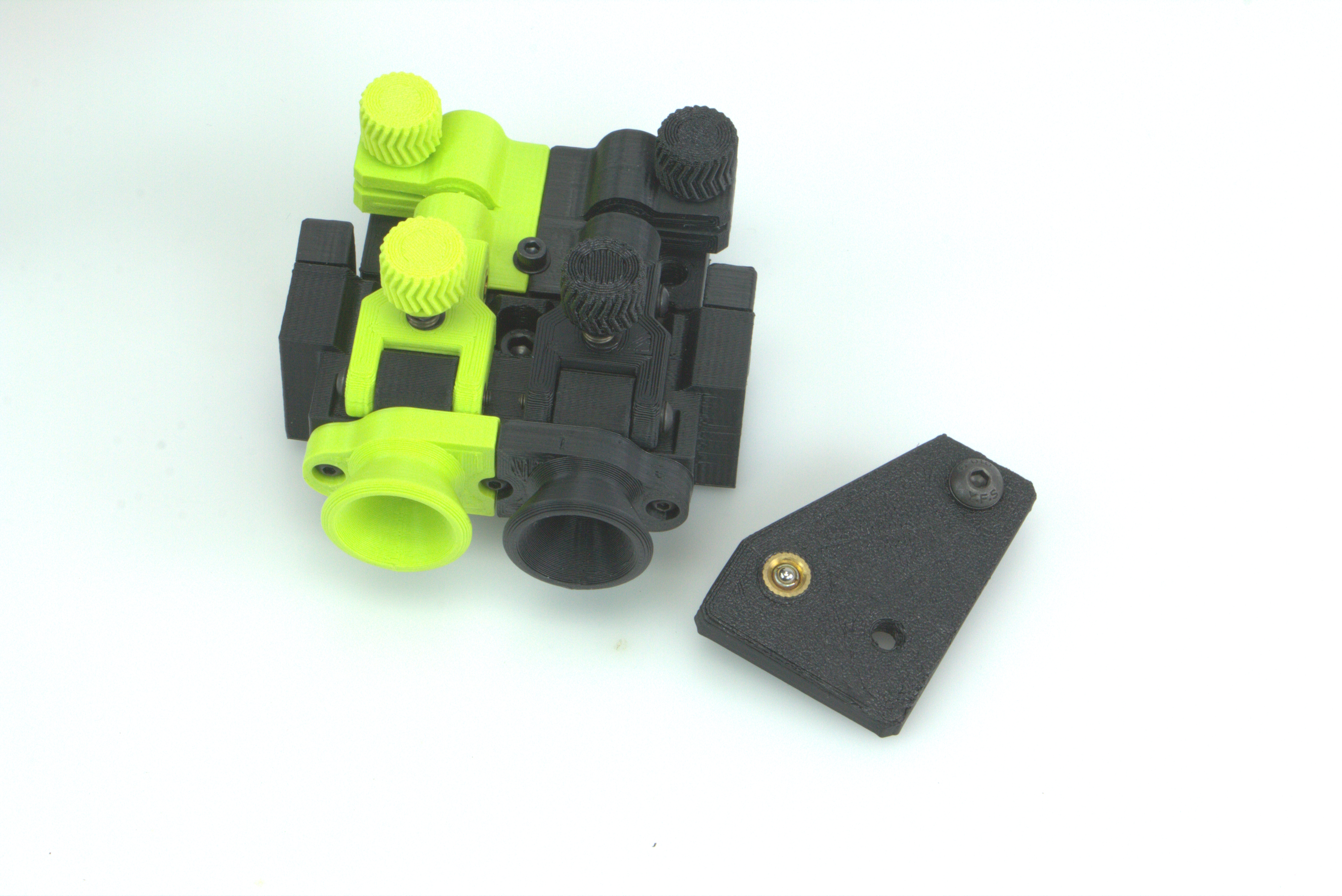
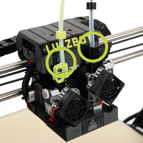
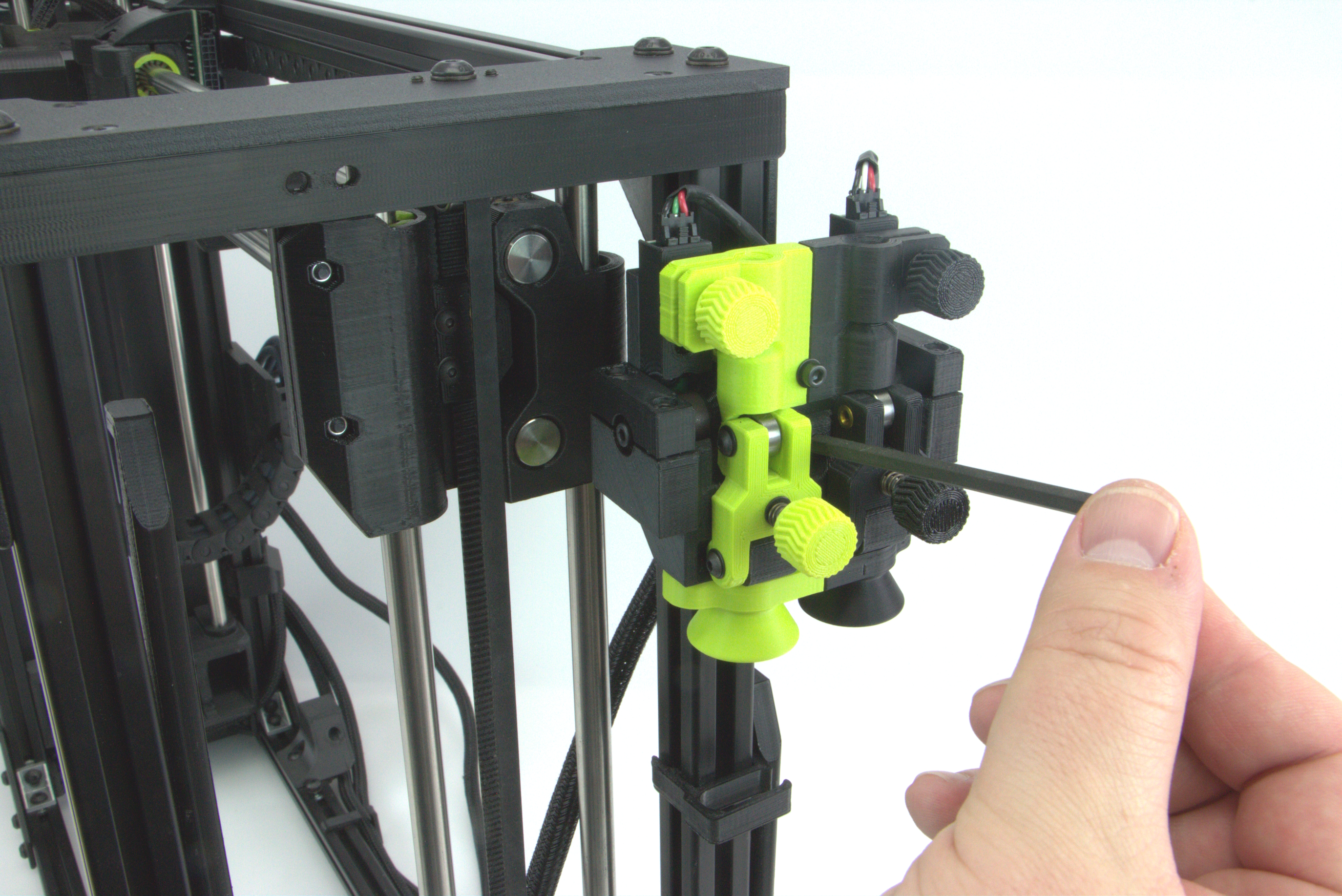
Remove the PTFE tubes from the runout sensor on the TAZ Pro and set aside.
Note if using the Dual Extruder, that each of the tubes will have a collar around them with the number 1 or 2 in green and black respectfully.
These will need to be installed in the correct place when installing them again.
Using the 4mm hex wrench, remove the single bolt holding the runout sensor on the printers frame and remove the sensor from the printer.
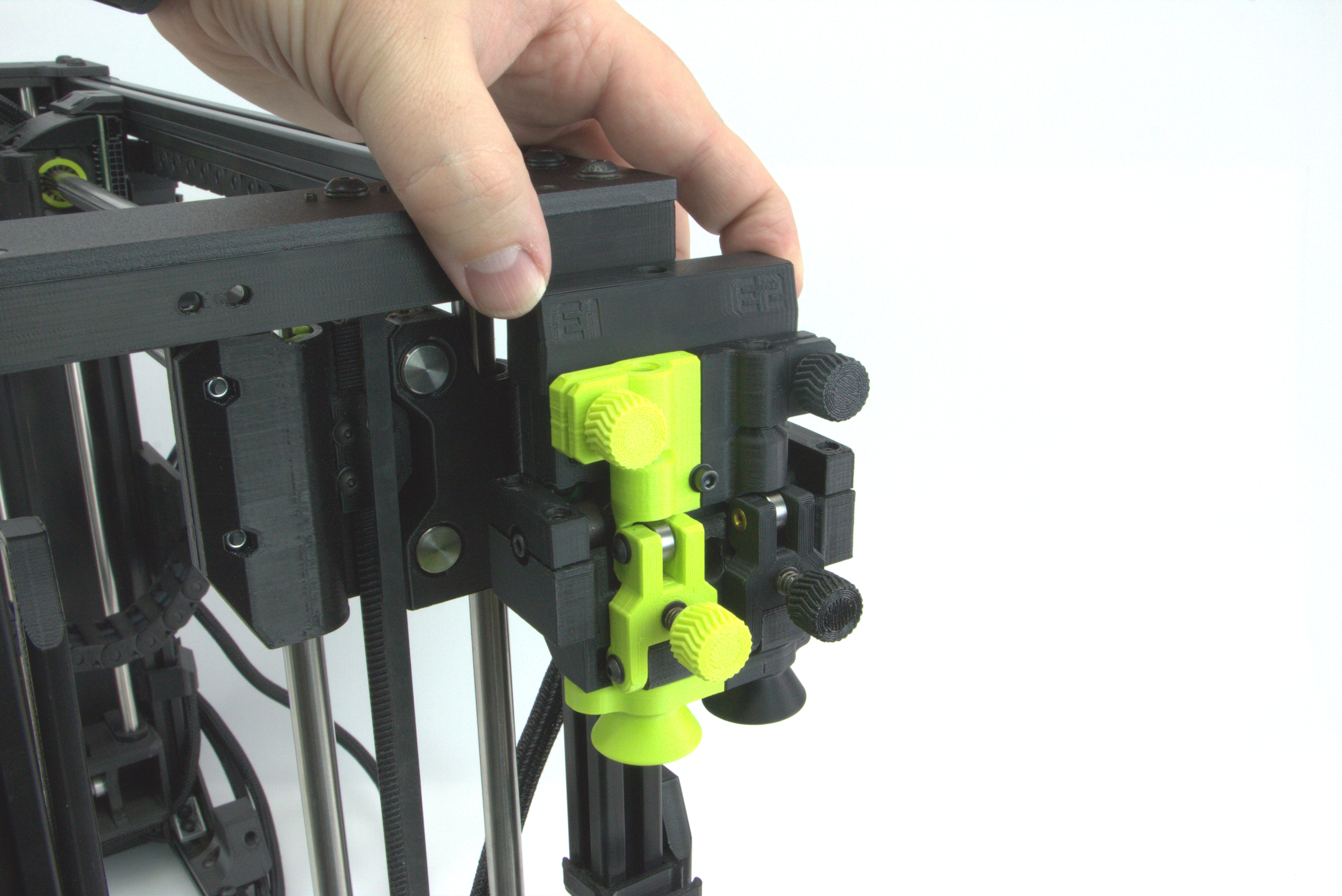
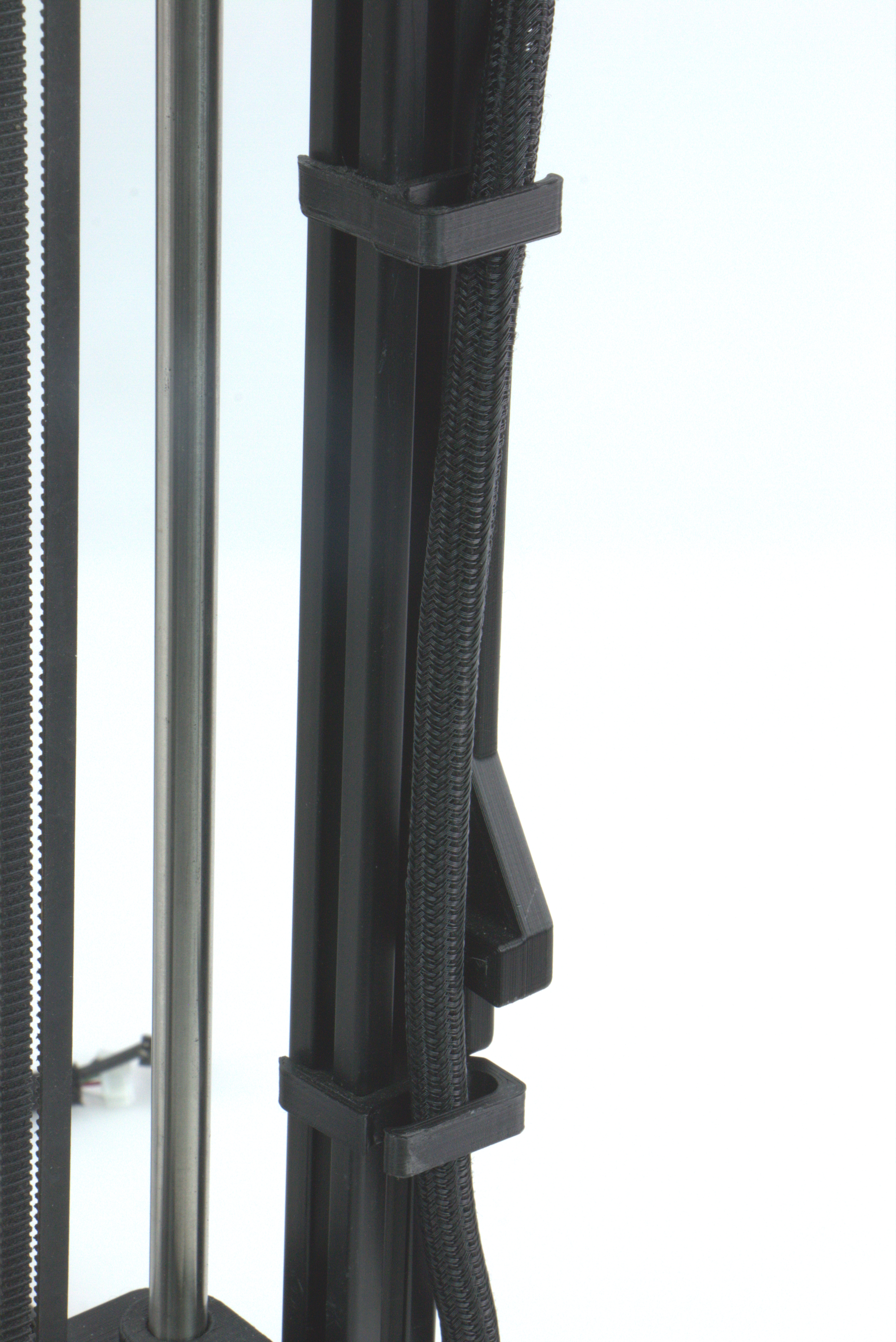
For the wiring harness, remove the harness from the clips holding it to the frame to make it easier to move the sensor around.
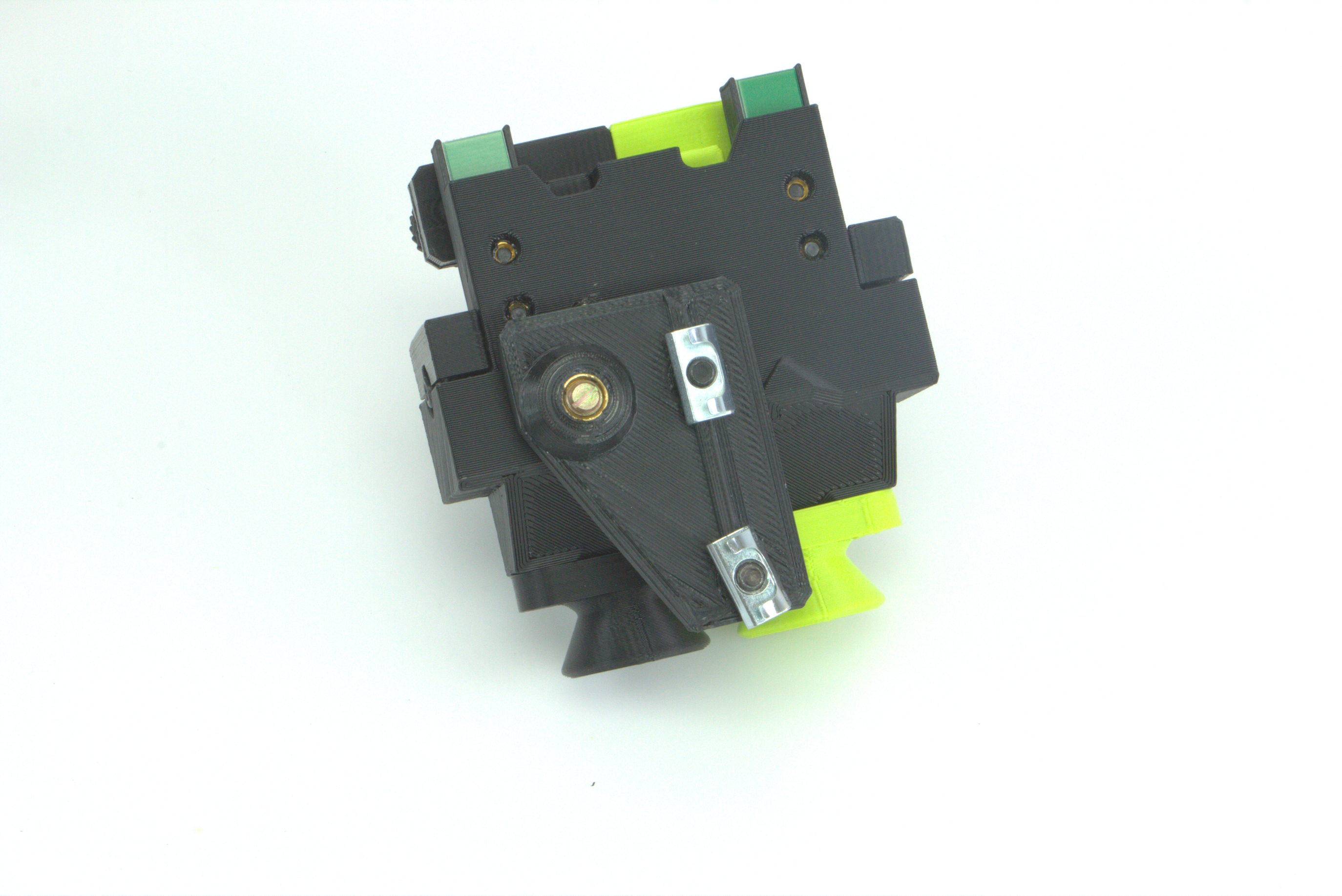
Remove the clips that cover up the runout sensor connectors.
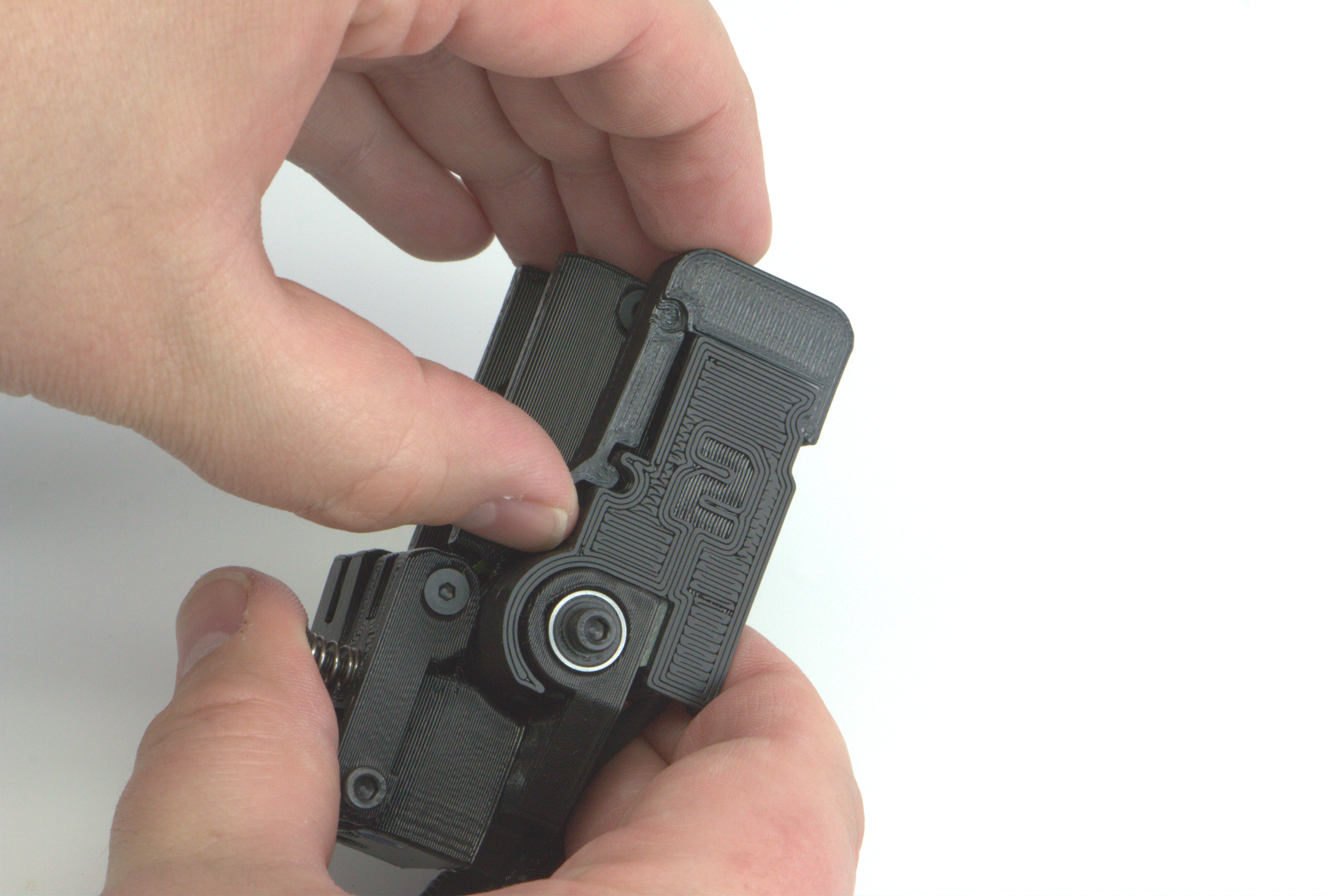
Turn the Runout sensor over and carefully route the harness away from the back of it.
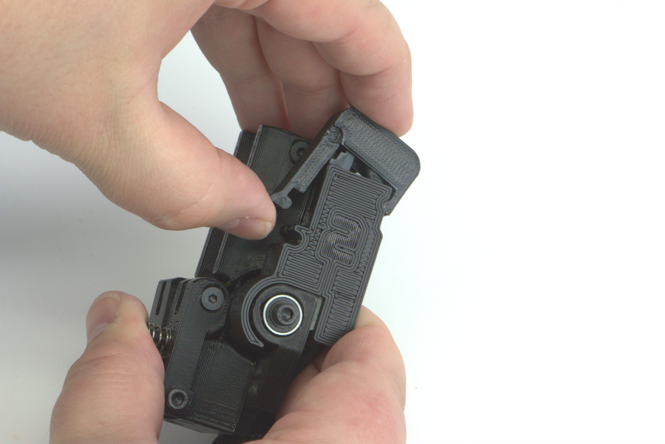
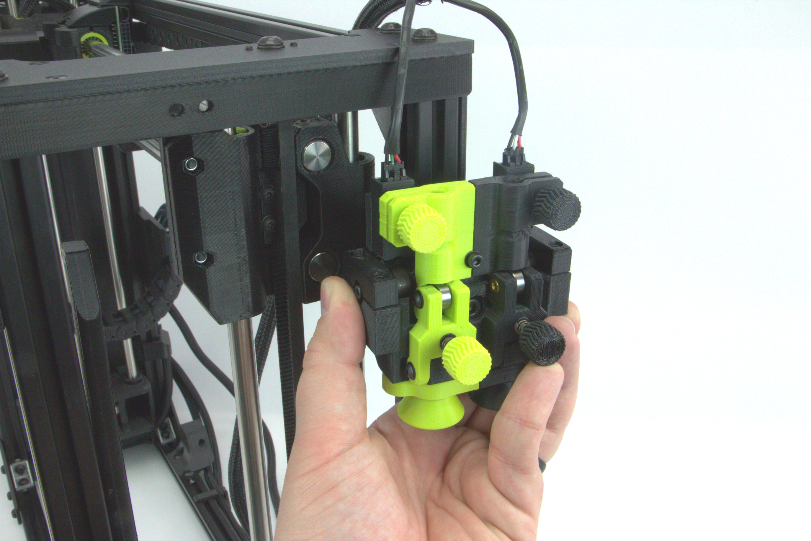
Disconnect the left side connector from the original runout sensor and connect it to the same side of the Jetpack sensor.
Disconnect the right side connector from the original runout sensor and connect it to the same side of the Jetpack sensor.
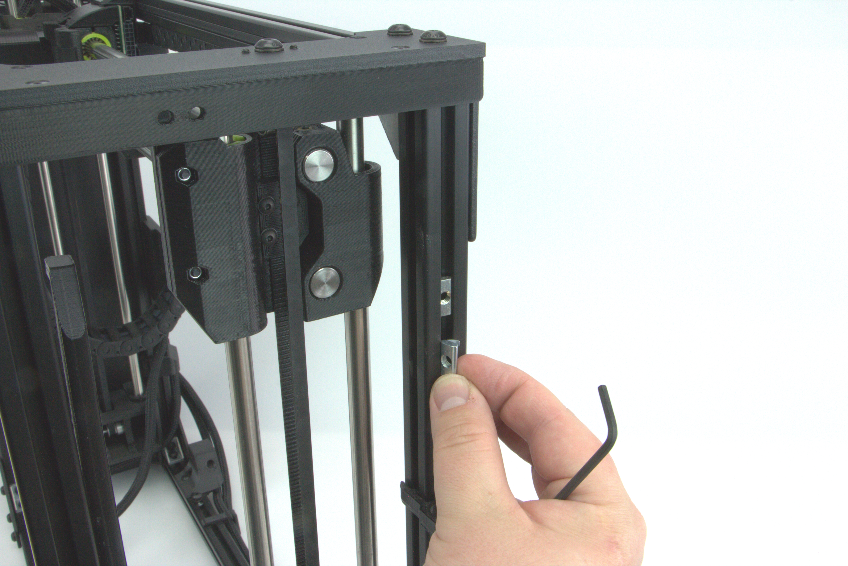
Install roll-in t-nut using one previously removed.
Slide t-nut in at and angle and push into frame.
If necessary, using a smaller hex wrench, insert into t-nut and lever it into position.
Alternatively, you can remove the lower foot on the printers frame and slide it into position within the extrusion.
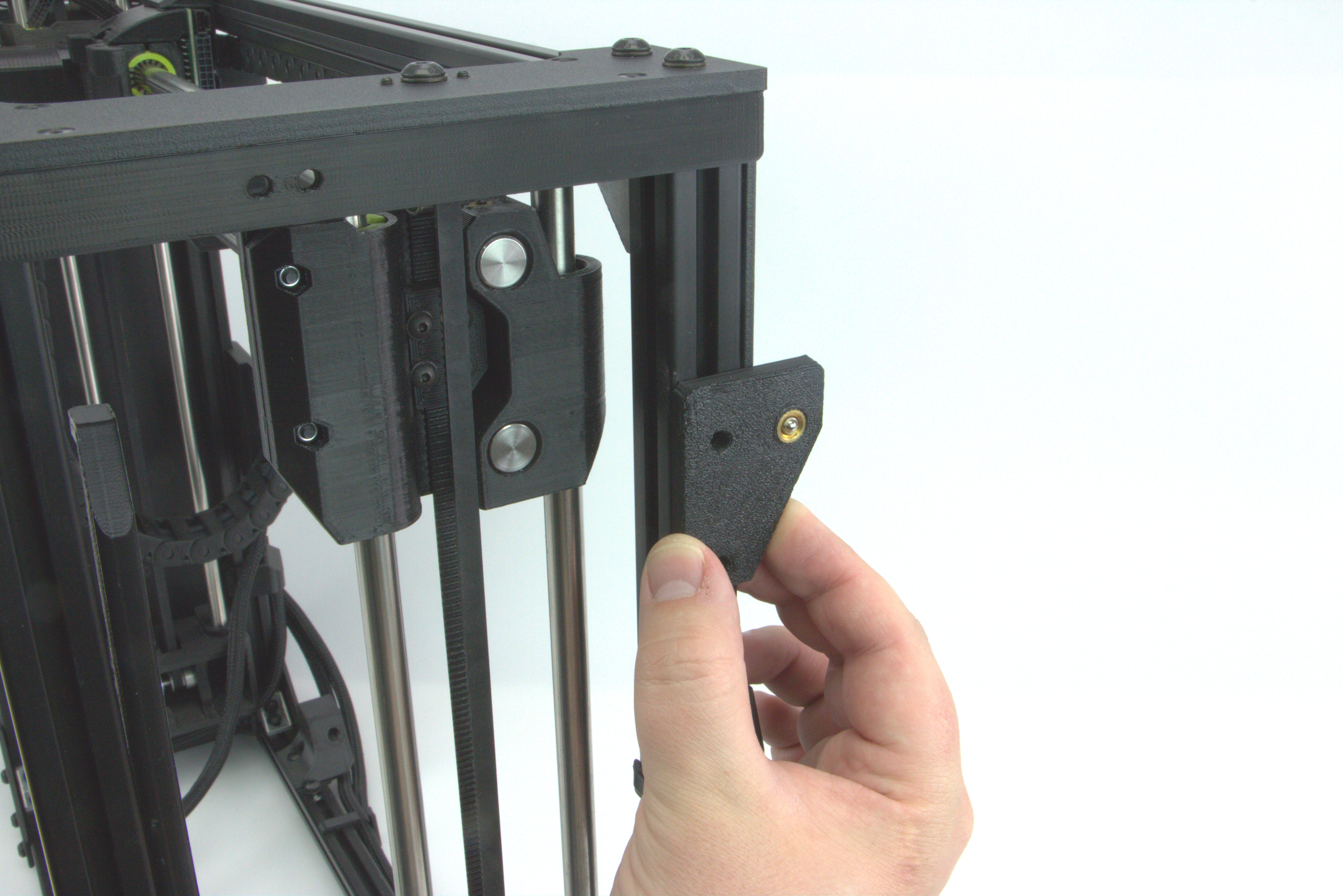
Align the mounting plate with the tab facing the rear of the printer.
Start lower screw using 3mm hex wrench. Do not tighten completely.
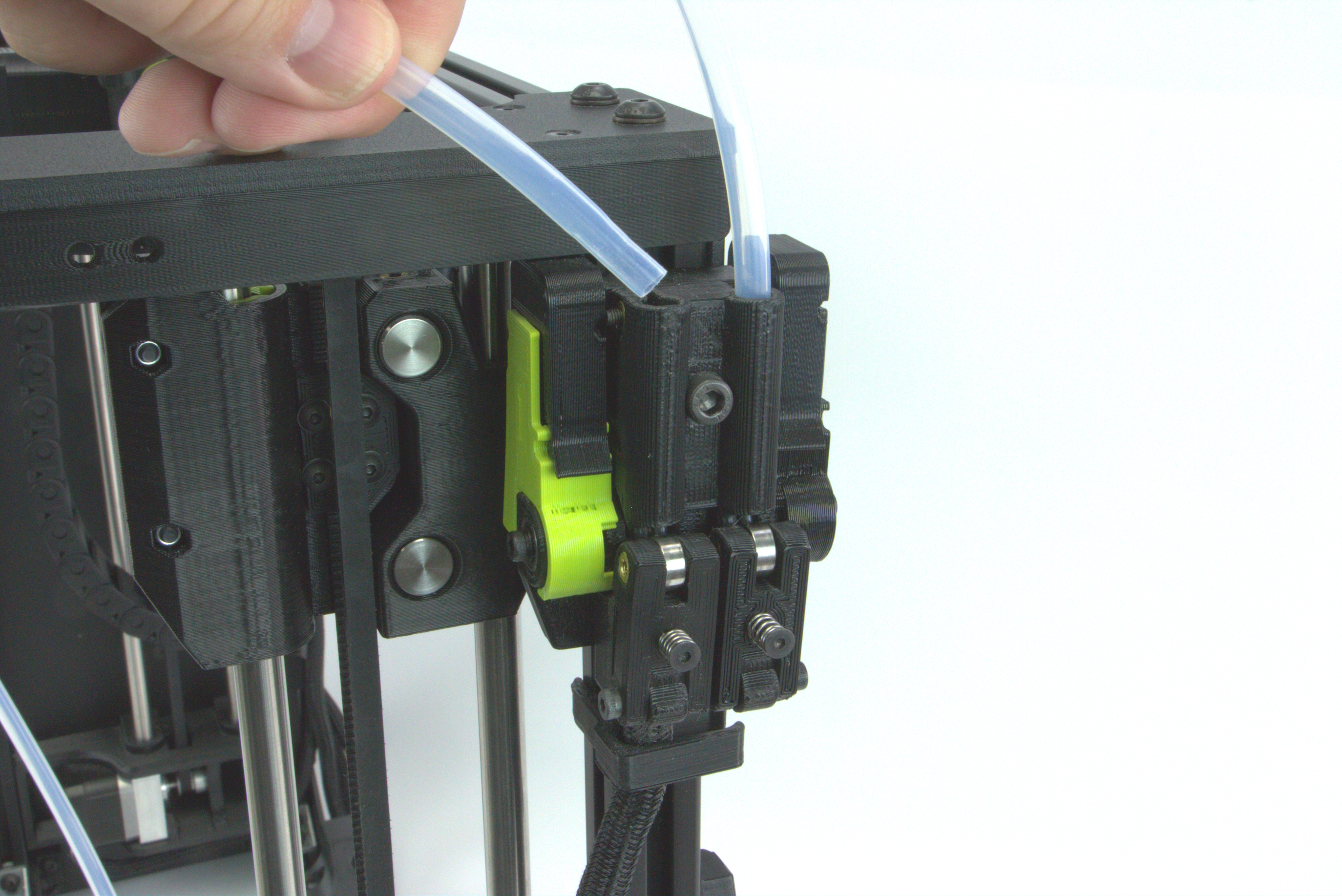
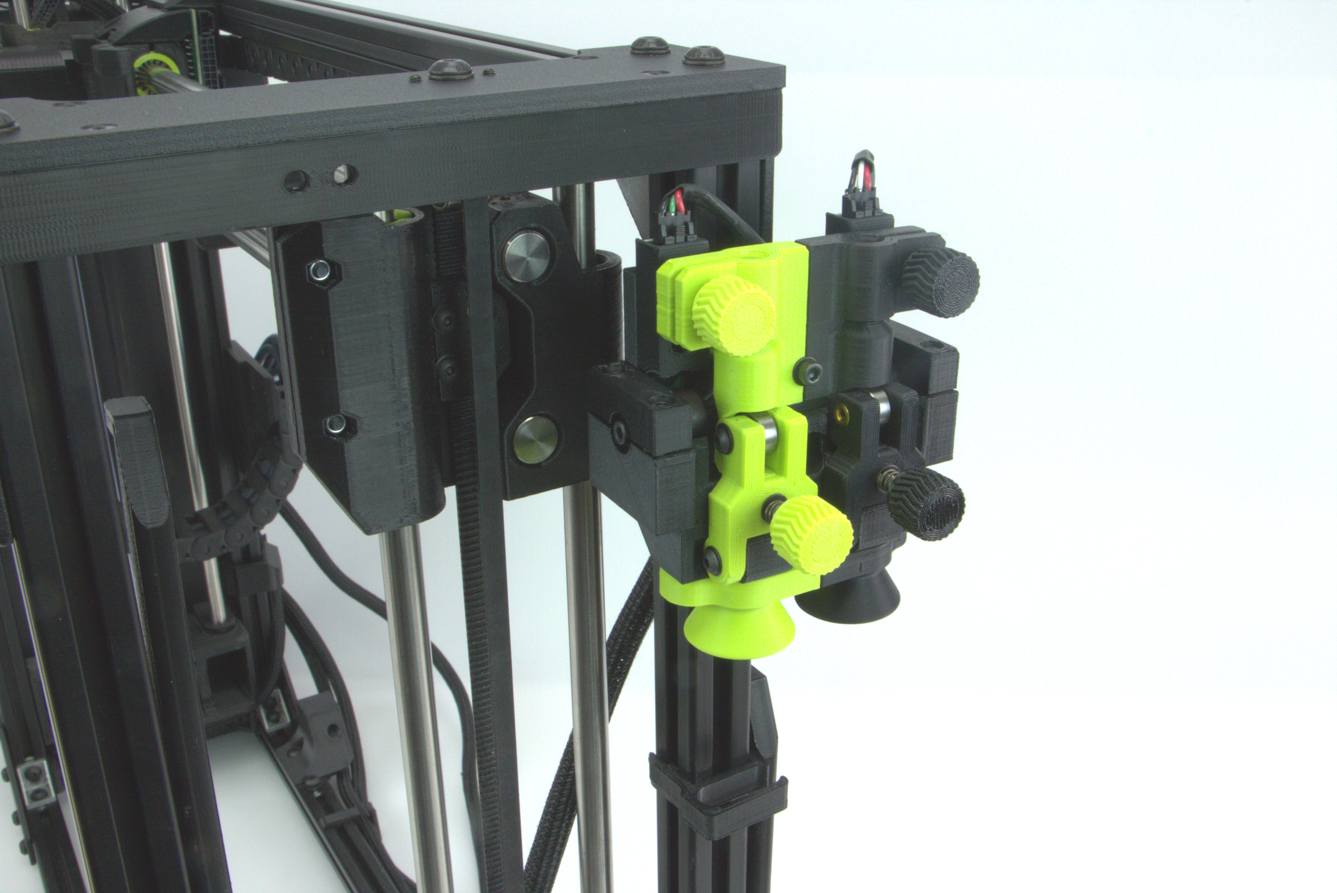
Place Jetpack Runout Sensor into position on the printer, were the previous sensor was installed.
When placing Jetpack onto printer, ensure that the harness is outside of the printer frame at the back.
If harness is routed inside the frame, the x-axis idler end can contact the harness causing damage.
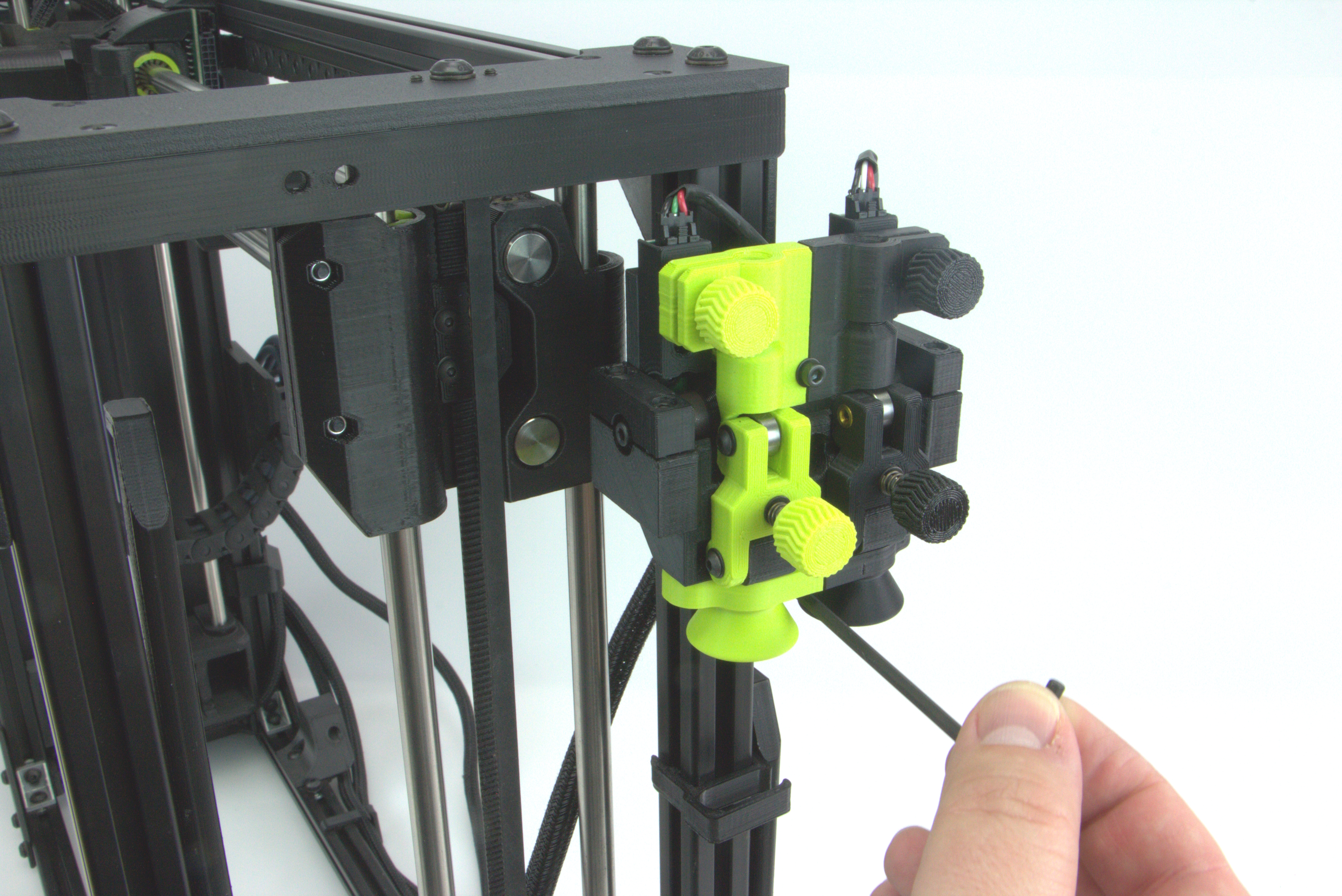
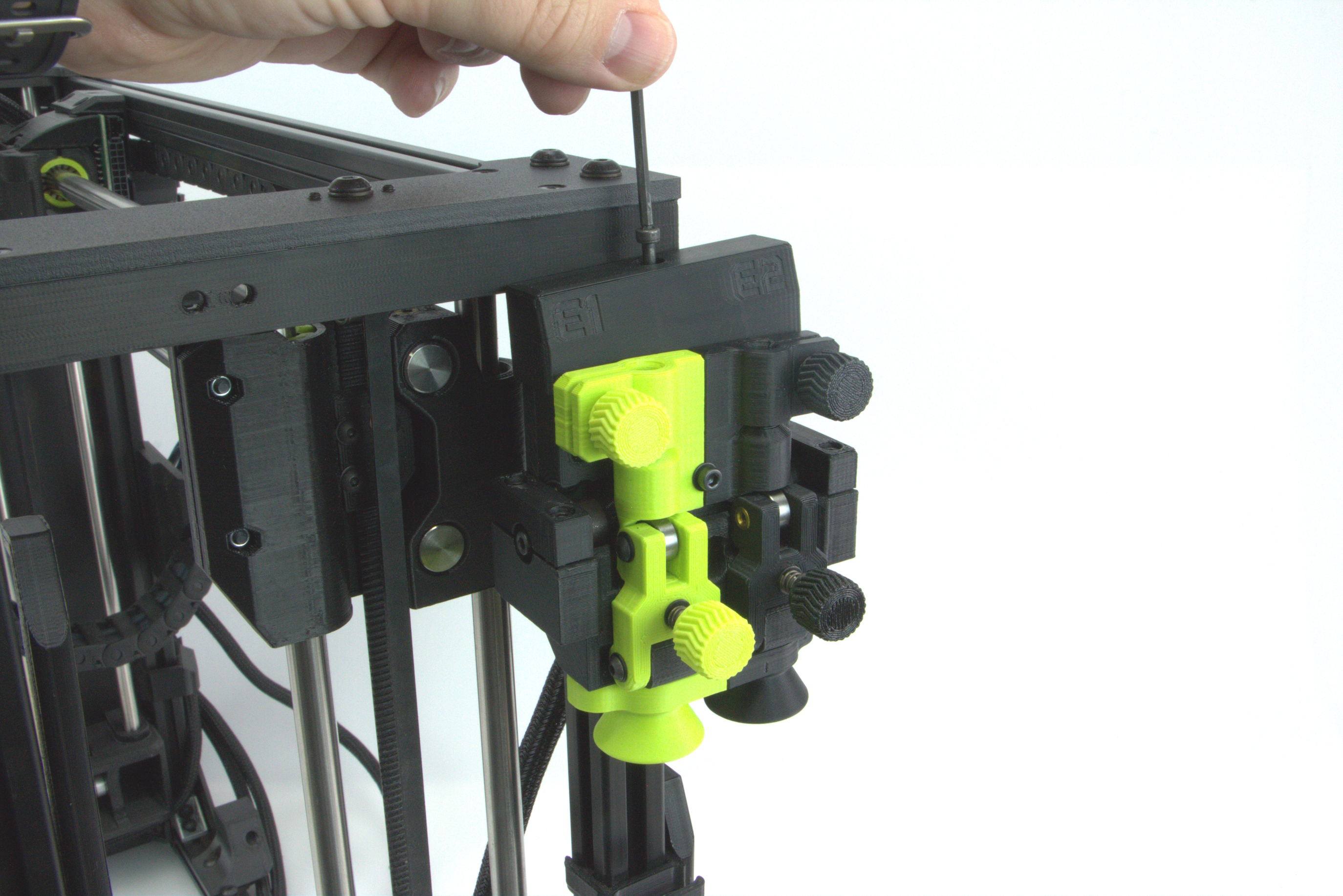
Using the 4mm bolt, start screwing the sensor into position but do not fully tighten.
Adjust the height of the runout sensor so it is able to rotate freely.
Fully secure lower m4 screw using a 3mm hex wrench.
When tightening the middle m5 screw using a 4mm hex wrench, check tightness by trying to rotate the Jetpack Runout Sensor.
You should be able to freely rotate it without a lot of resistance. If there is too much resistance, loosen the middle screw a little bit and test again.
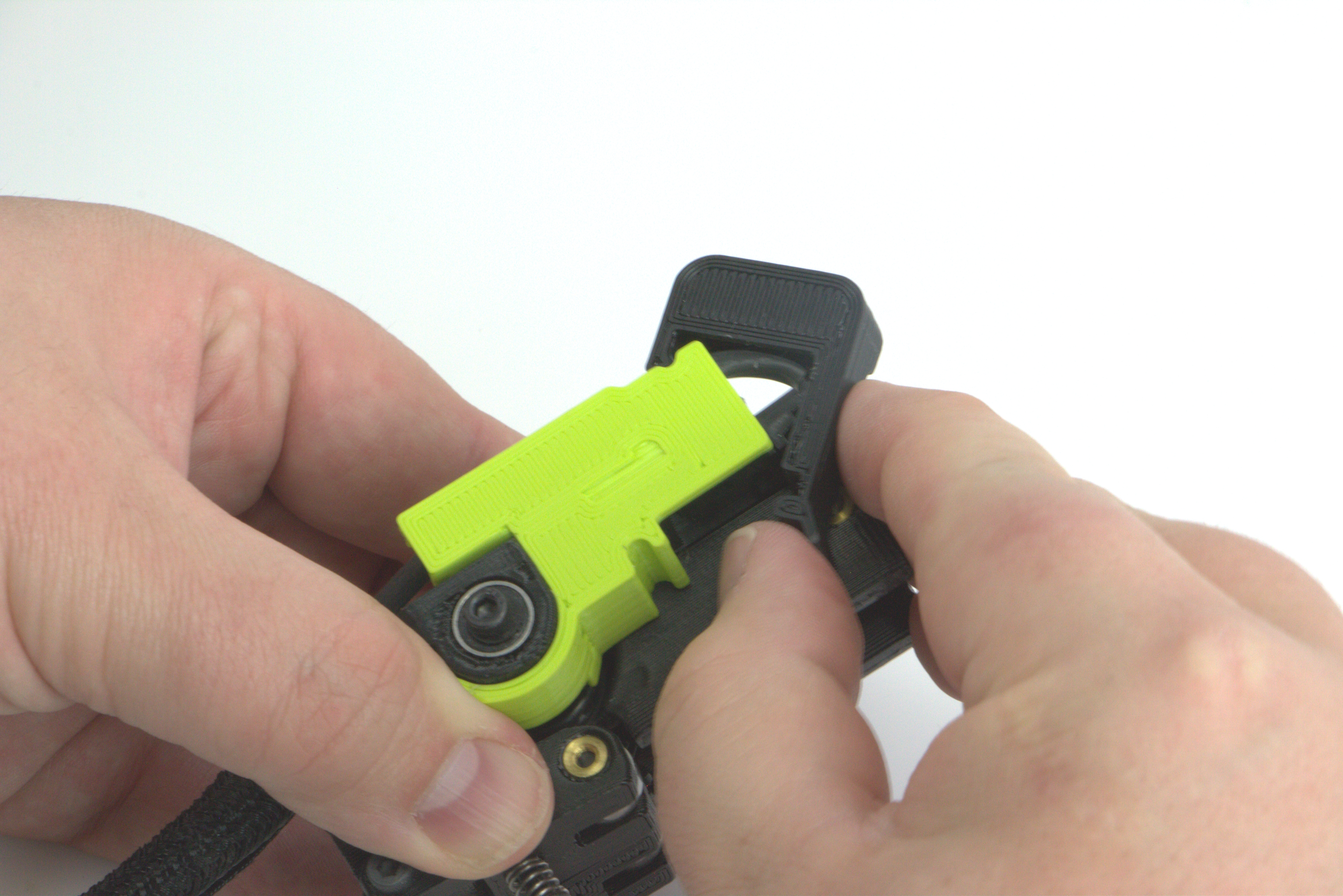
Install the connector cap onto the top of the runout sensor, being careful not to pinch the harnesses.
Secure the cap using the provided m3 screw and a 2.5mm hex wrench.
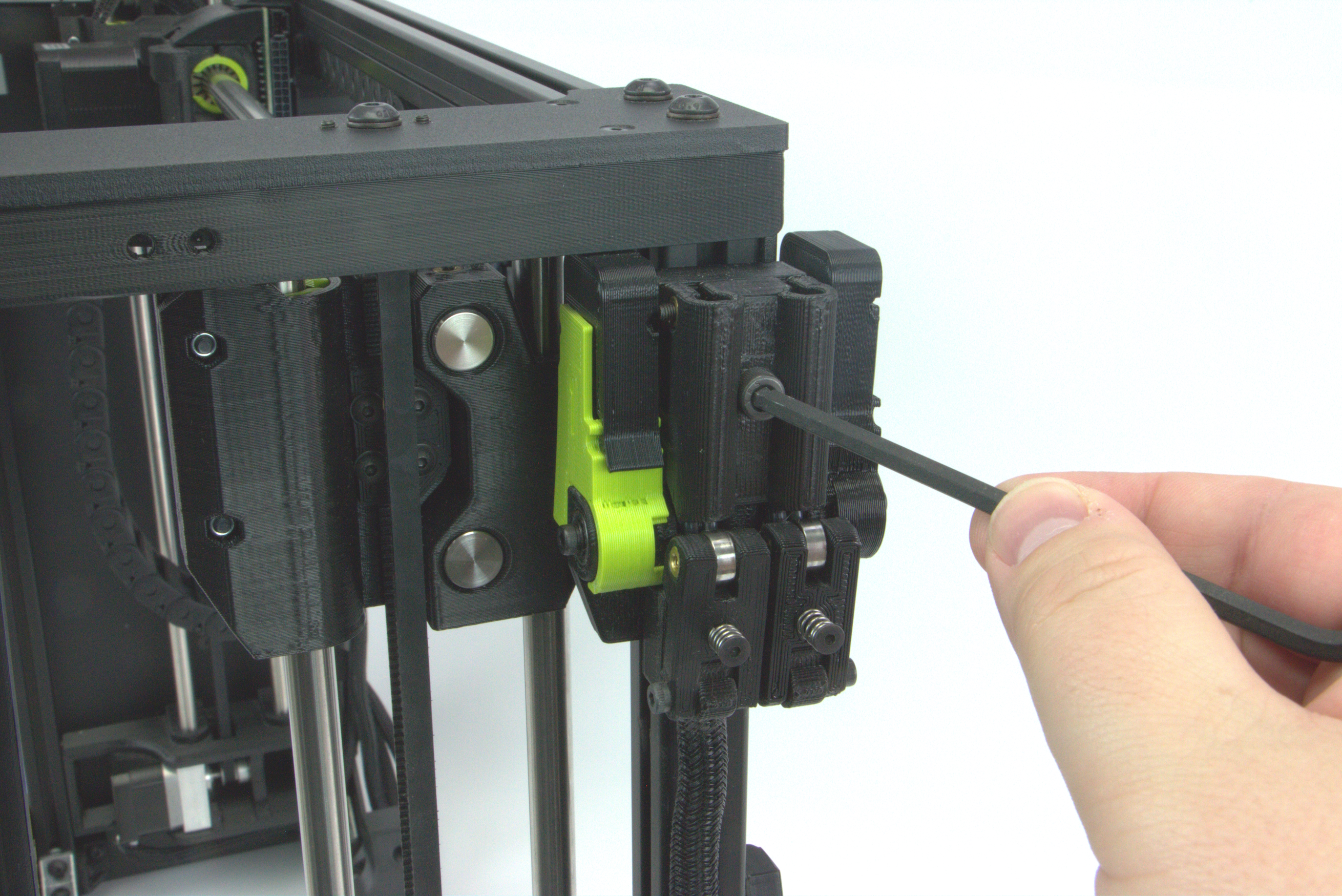
Route the harness to the side of the printers frame and insert it back into the harness clips.
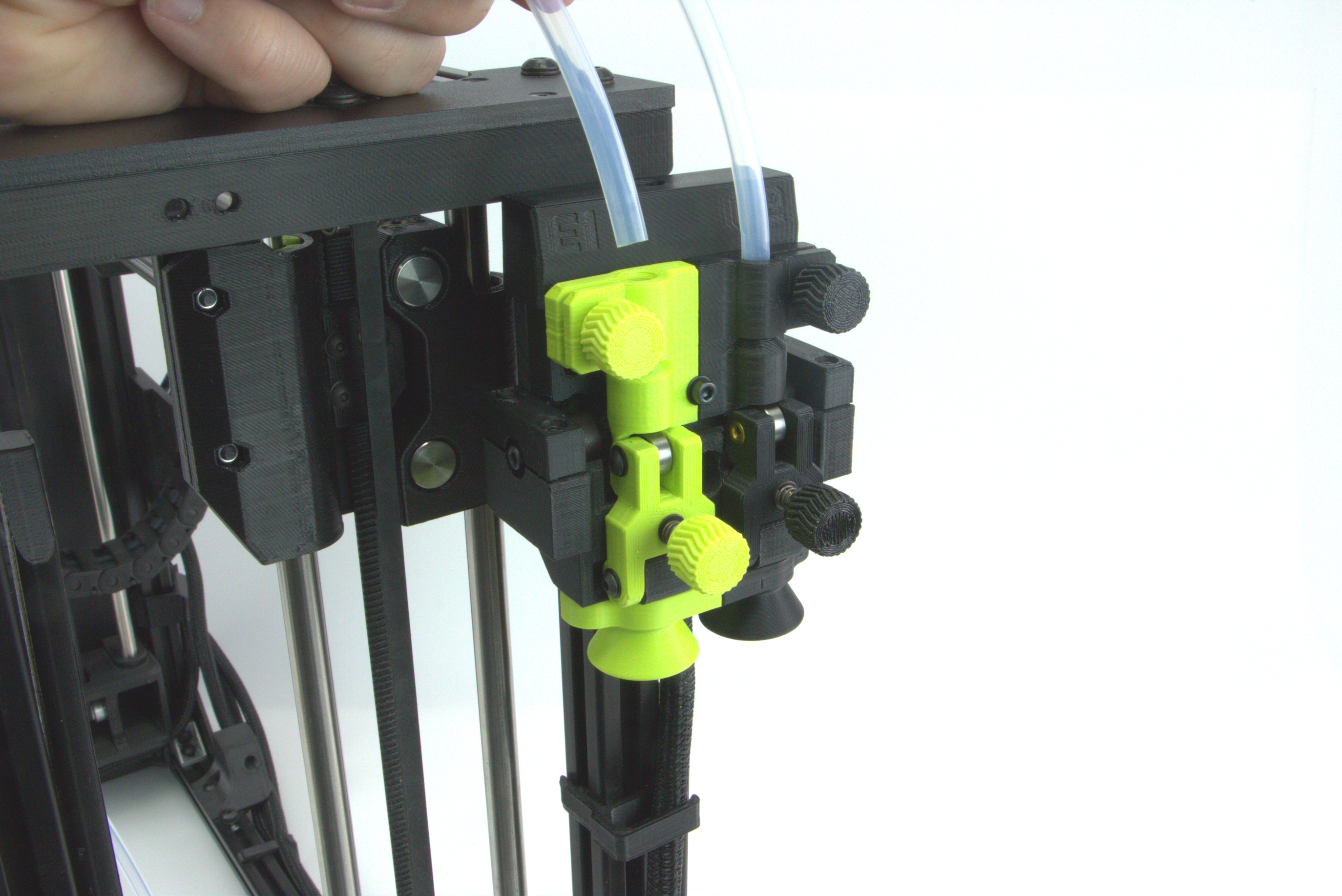
Install the PTFE tubes into the top of the runout sensor.
If using two PTFE tubes with the TAZ Pro Dual Extruders, be sure that the correct 1/green and 2/black sensor is installed in the correct location on the sensor.
If using a single extruder tool head, be sure to use the green side of the runout sensor.
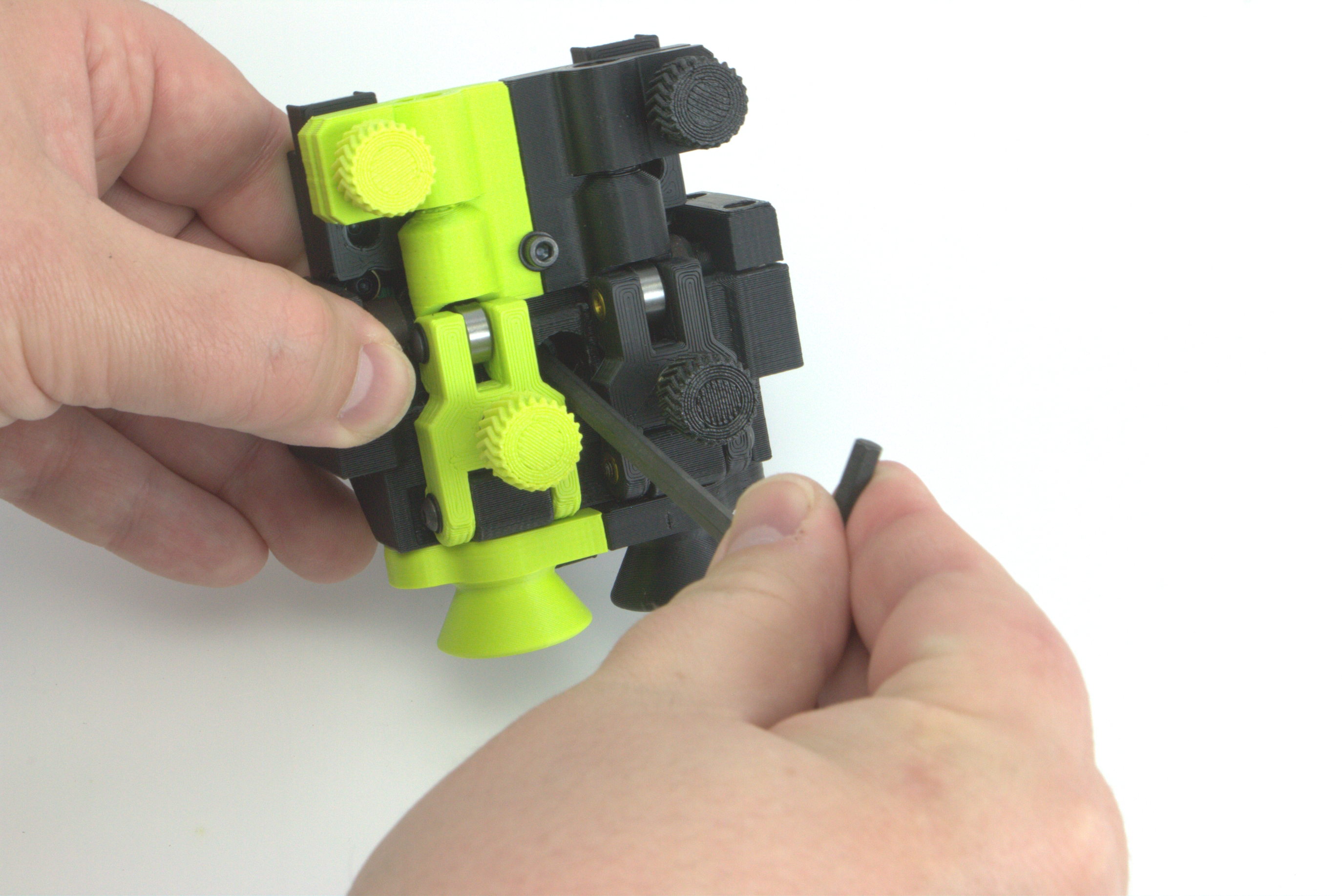
Gently tighten the upper thumb screw to secure the PTFE tube in place. Do not over tighten as this does not need to be very tight.
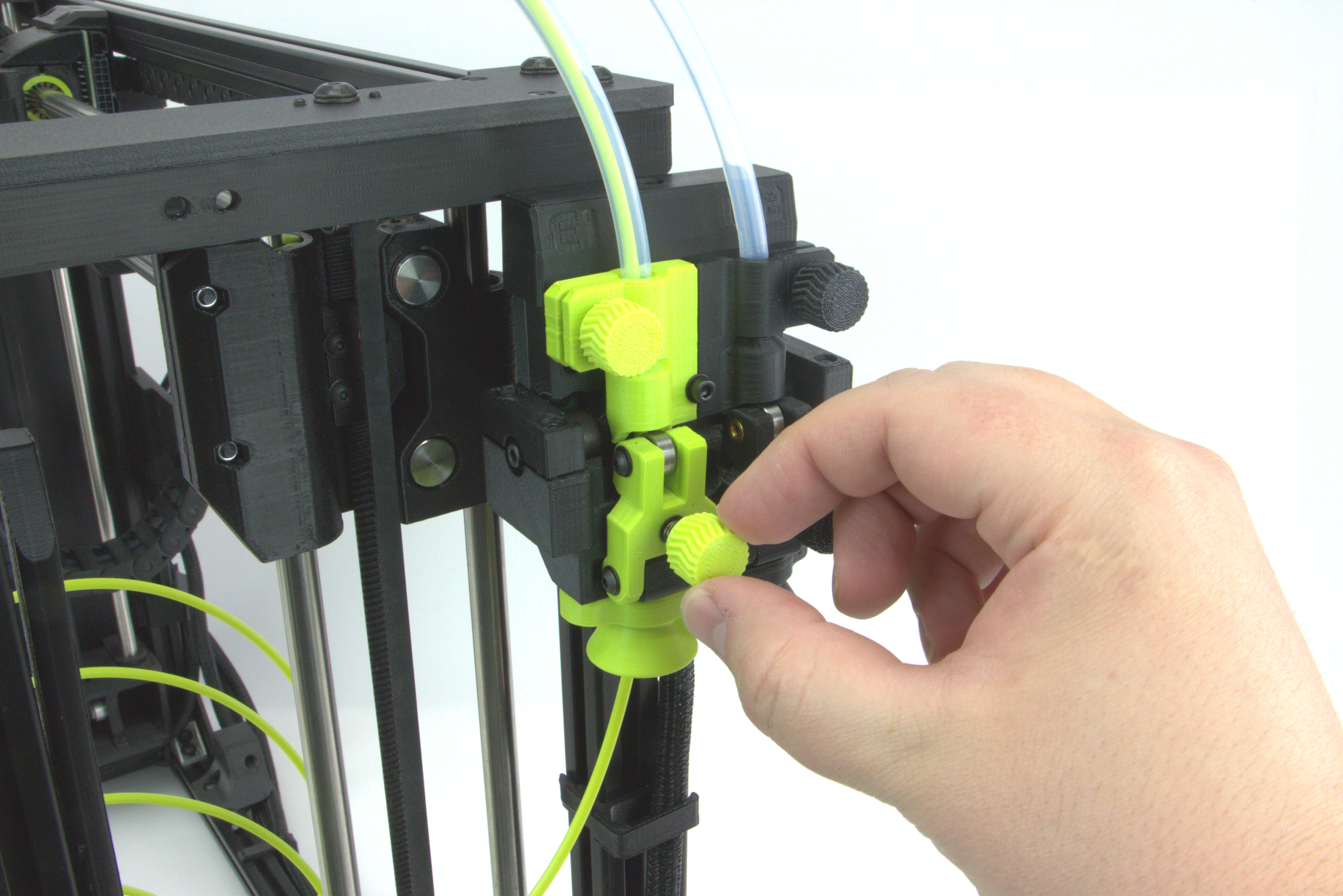
Insert your filament into the runout sensor and feed it through the PTFE guide tube.
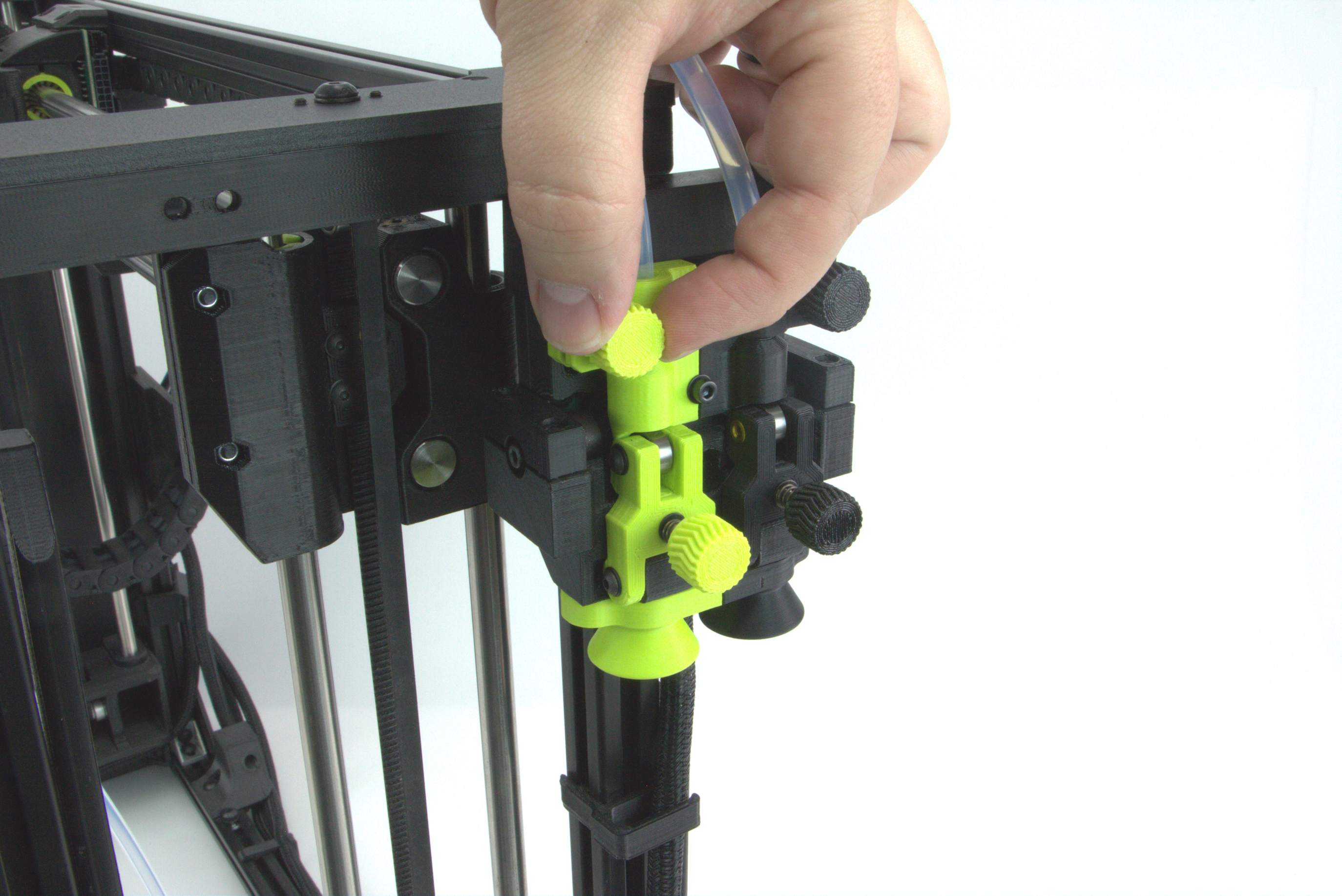
Depending on the tension of the filament going through the runout sensor, you may need to adjust the lower thumb screw for smoother feeding.
Pull the filament through the PTFE tube and if it feels too tight and takes a lot of effort to pull the material, loosen the thumb screw a little bit.
Be sure not to tension it too much as a tension that is too loose may cause detection issues when printing.
Spin the spool of filament to pull the material that you used to test tension back onto the spool and insert the filament end into the tool head.
Be sure to connect the PTFE tube end into the Tool Head to ensure there is no slack in the guide tube.
Plug your printer in and turn it on. You are ready to print with your newly installed TAZ Pro Jetpack: Jam & Runout Sensor Kit!