Open HardwareAssembly Instructions
Guides for installation and assembly of the LulzBot line of products made by FAME 3D LLC.
Guides for installation and assembly of the LulzBot line of products made by FAME 3D LLC.
Gather parts:
Parts:
1x- Z switch mount (PP-GP0216)
1x- Wiper Mount (PP-GP0231) and Wiper pad
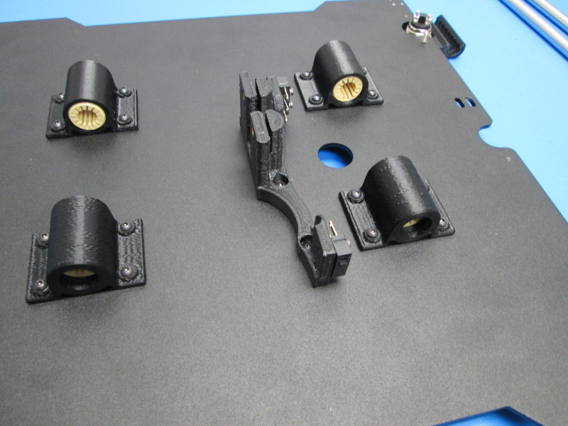
4x- Bearings Holder (PP-GP0233) (with bearings installed)
4x- Bed corners (PP-GP0221)
1x- Y belt mount (PP-GP0222)
1x- Bed plate
4x- Bed standoffs
1x- Momentary switch and retention nut
2x- SPDT switches
1x- M3x16 FHCS
30x- M3x8 BHCS
4x- M2x10 SHCS
1x- M3x10
30x- M3 black washers
4x- M2 washers
Tools:
5.5mm Nut driver
1.5 mm Hex driver
2.0mm Hex driver
Instructions
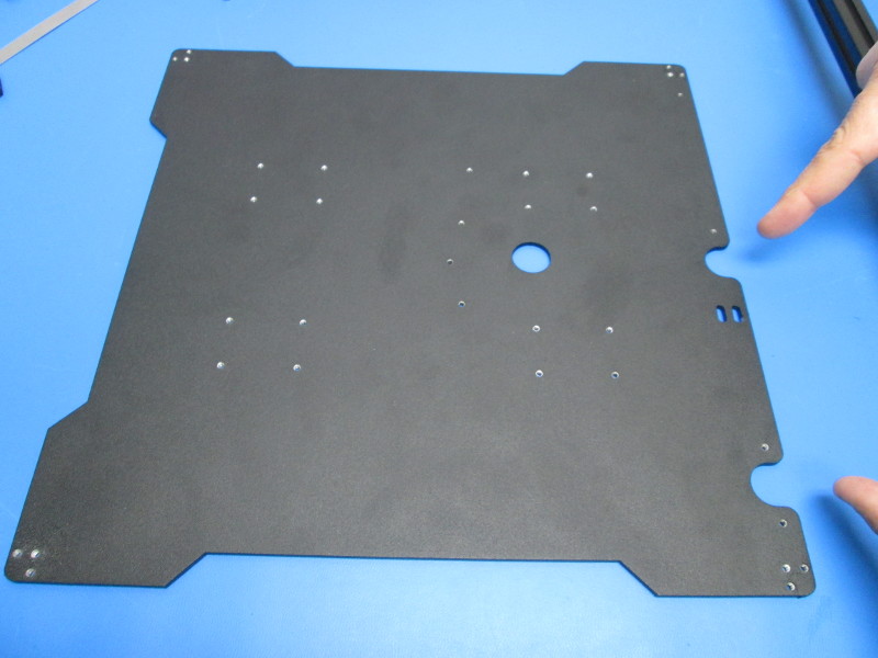
Place the bed plate flat, be sure it is indexed as shown.
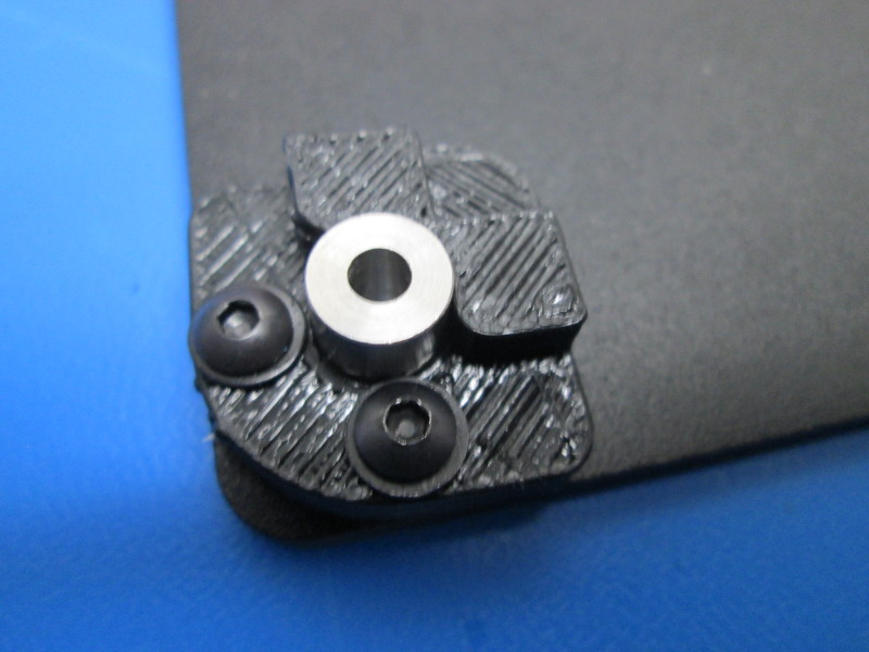
Loosely attach the bed corner and standoff with two (2) M3X8 BHCS and two (2) M3 Black washers to each of the four (4) bed corners to the plate. These will be tightened later when the bed is attached.
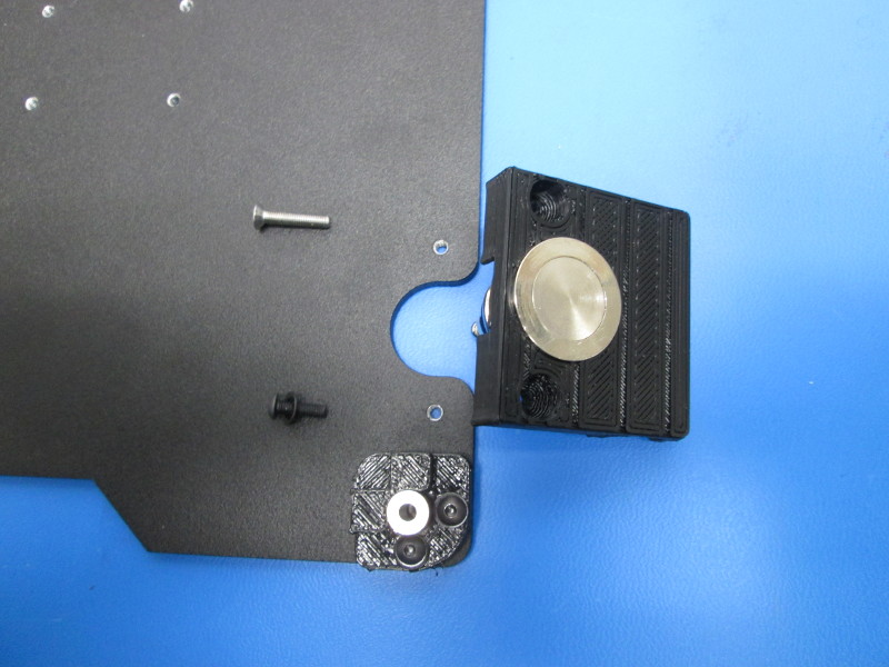
Using two (2) M3X8 BHCS and two (2) M3 Black washers loosely attach the wiper mount to the plate as shown. These will be tightened later when the bed is installed.

Flip the plate over;
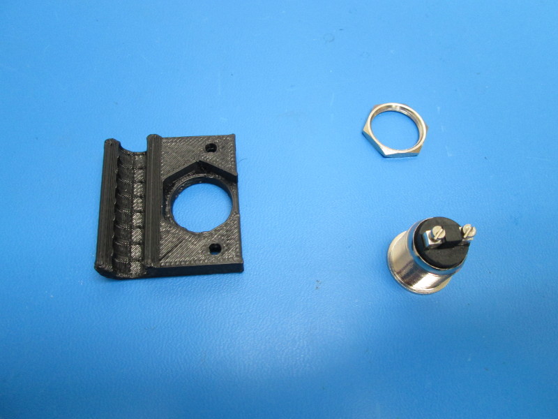
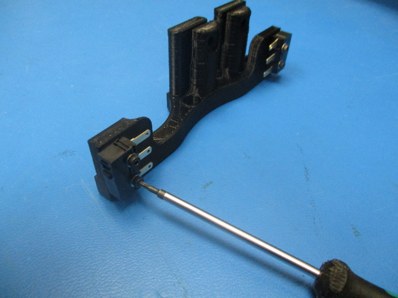
Install the momentary switch into the Z mount switch toque to 3in*lbs
Correct the orientation of the two switch contacts to a perpendicular orientation to the cable pathway (seen to the right of the switch)
Loosely secure the Z switch mount to bed plate. Use one (1) stainless M3X16 FHCS towards the inside of the plate, one (1) M3X10 BHCS and one (1) M3 Black washer on the other side. These will be tightened later when the bed is installed.
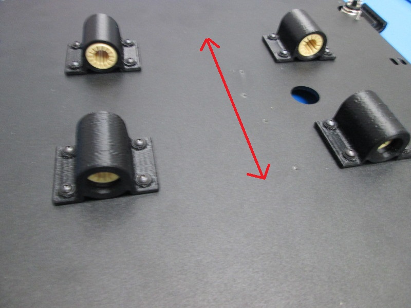
Loosely secure the Y bearings to the assembly using sixteen (16) M3X8 BHCS and sixteen (16) M3 black washers
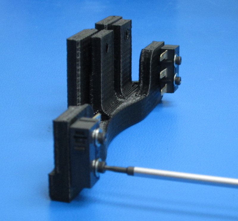
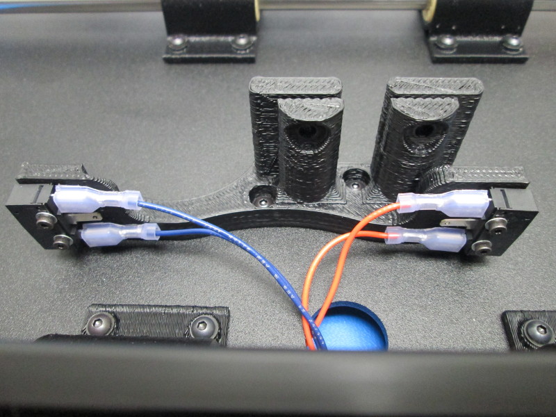
Install two (2) SPDT switches using two (2) M2x10 SHCS, secured to hand tight, and two (2) M2 washers onto each end of the Y belt mount with wiring terminals facing each other and the switch actuator away from the plate
Install the belt mount as shown using four (4) M3X8 BHCS, tightened to 3 in-lbs (~.35 N-m), and four (4) M3 Black washers making sure the long switch side is toward wiper mount side of the bed plate.
Parts:
20x- M5x10 BHCS
16x- M5 Black Washer
1x- M8x35 BHCS
4x- M8 Washers
2x- 608 bearings
4x- M3x12 BHCS
4x- M3 Black washers
1x- M3 Star washer
4x- M3x6 Set screws
2x- 500mm aluminum extrusions
16x- M5 T-Nut
8x- M5x10 BHCS
Tools:
Needle nose pliers
3mm ball end driver
2mm ball end driver
5.5mm nut driver
Y pulley spacer
Flush cutters
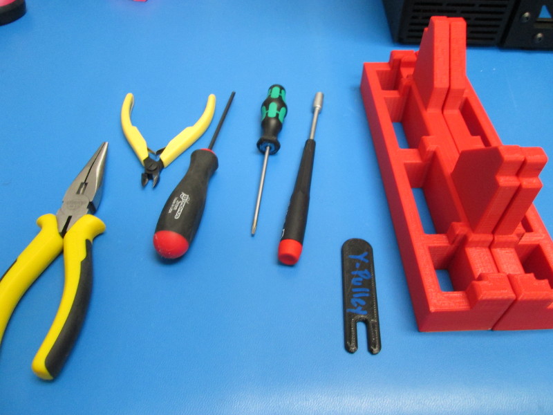
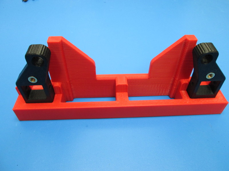
Place one (1) Left and one (1) Right Y Corner (bottom side of print out) into each of the Y table assembly jigs. The Y assembly jig is a 2 piece fixture that must be used together.
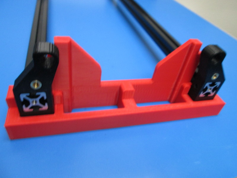
Insert aluminum extrusion into each of the Y corners in one of the Y assembly jigs. Attach these extrusions to the Y corners that are in the second Y assembly jig.
Position the extrusions so they are flush to the end of the Y corners.
Place one (1) T-nut in the left and right side slots on each end of the aluminum strut. (8 used)
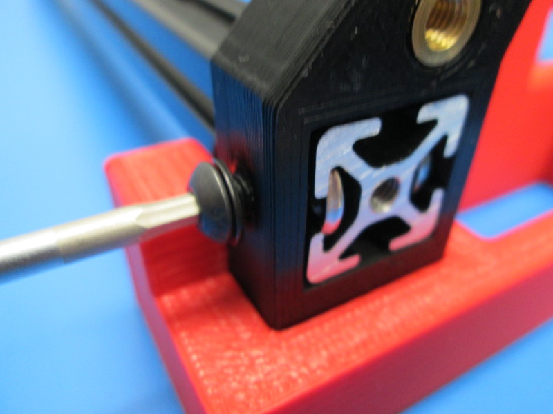
Insert one (1) M5X10 BHCS through each hole hole on the sides of every Y corner;
Position a T-Nut in line with each hole and screw. Ensure the extrusion ends are still flush with the T-Nuts, tighten screws to 12in-lbs.
Install four (4) T-nuts into the top slot of each aluminum extrusion (8 total). Tighten to approximately 12 in-lbs.
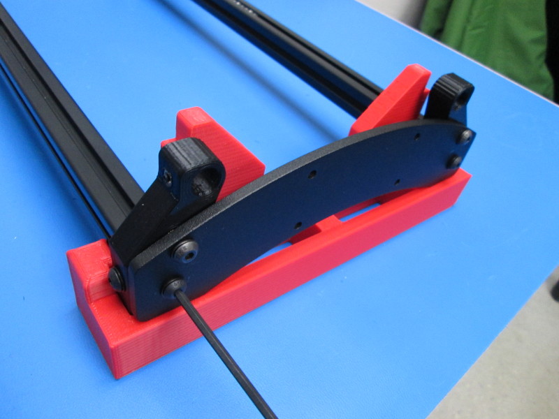
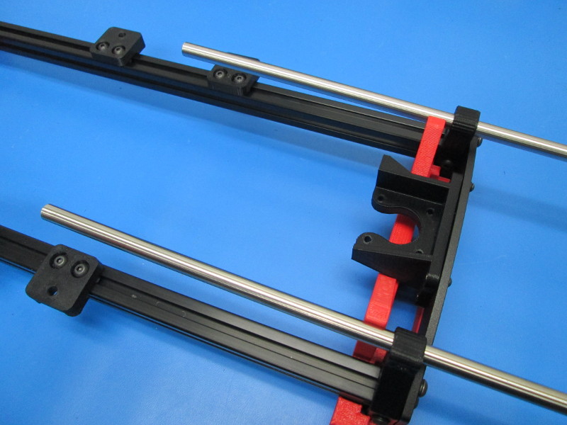
Place the Y Axis Idler end assembly on one end of the Y table (Idler assembly must be oriented toward the second Y assembly jig), use four (4) M5X 10 BHCS and four (4) M5 Black washers to attach the Y axis Idler end assembly to the two extrusions. Make sure to leave this loose for now.
Place the Y Axis Motor End assembly on the other end of the Y table and use four (4) M5X10 BHCS and four (4) M5 Black washers to attach the assembly to the extrusions. Make sure to leave this loose for now.

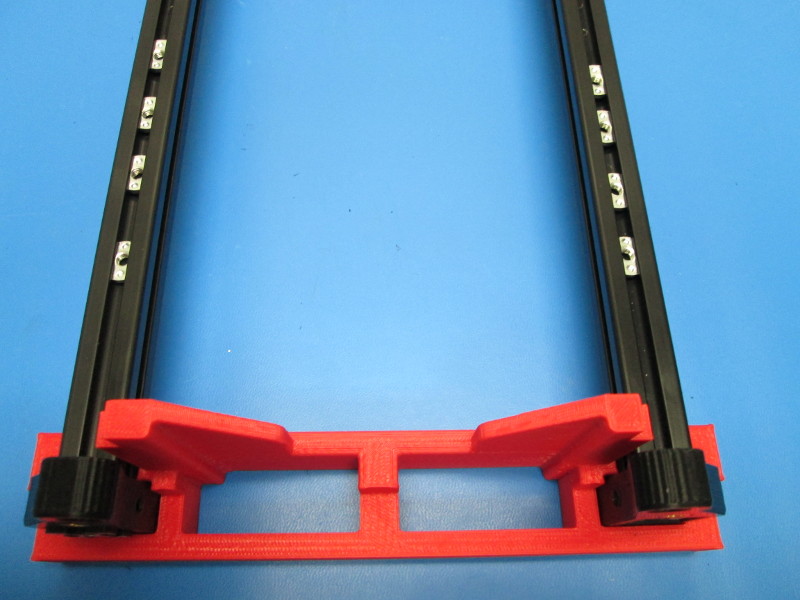

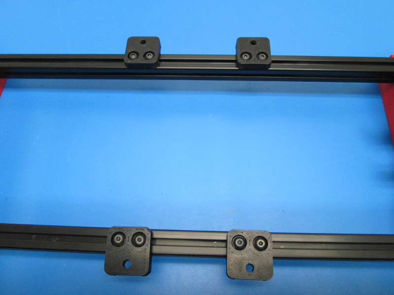
Secure the four (4) Y table mounts to the top of the extrusions using two (2) M5X10 BHCS and two (2) M5 black washers for each Y table mount. Snug these down.
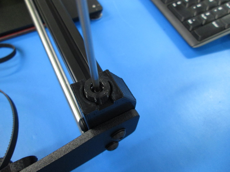
Install the guide rods in Y corners, and push them approximately halfway through the Y corners.
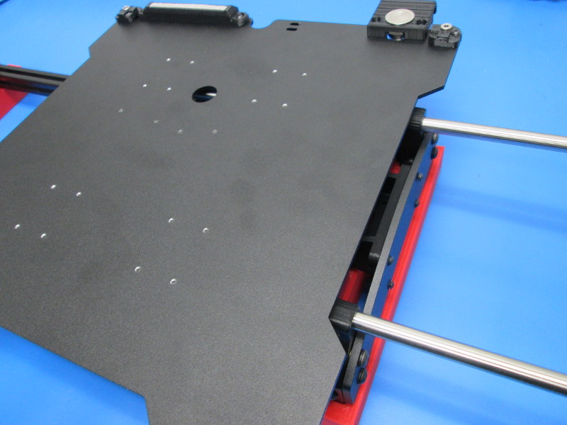
With the Y idler end positioned to the left, motor end positioned to the right, orient the bed assembly with the switch side oriented away from you;
Slide the bed plate assembly onto the Y rods, then slide the rods the rest of the way through to the the opposite side Y corners
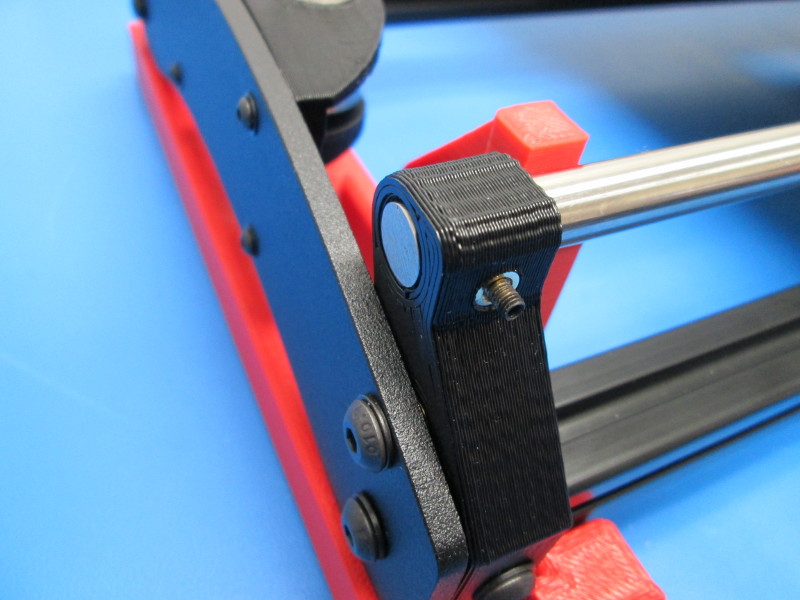
Set the Y rods flush to the Y corners, install one (1) M3 set screw into each of the Y Corner M3 inserts, tighten the set screws to ~2 in-lbs.
The guide rods aluminum extrusion should be supported by the Y table alignment jigs. It is imperative that the guide rods are supported by the jig or the Y table will not be aligned properly.
Starting with the two bottom screws on one then moving to the top screws of that side, Tighten the four (4) M5X10 BHCS to hand tight; repeat for the other side (bottom first, then top).
Flip the assembly over and slide the bed assembly to the motor side of the assembly.
Then, tighten the motor side bearings down to 5in-lbs. Slide to the idler side and tighten the idler side bearings to 5in-lbs.


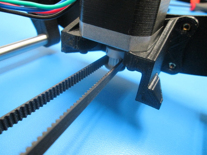
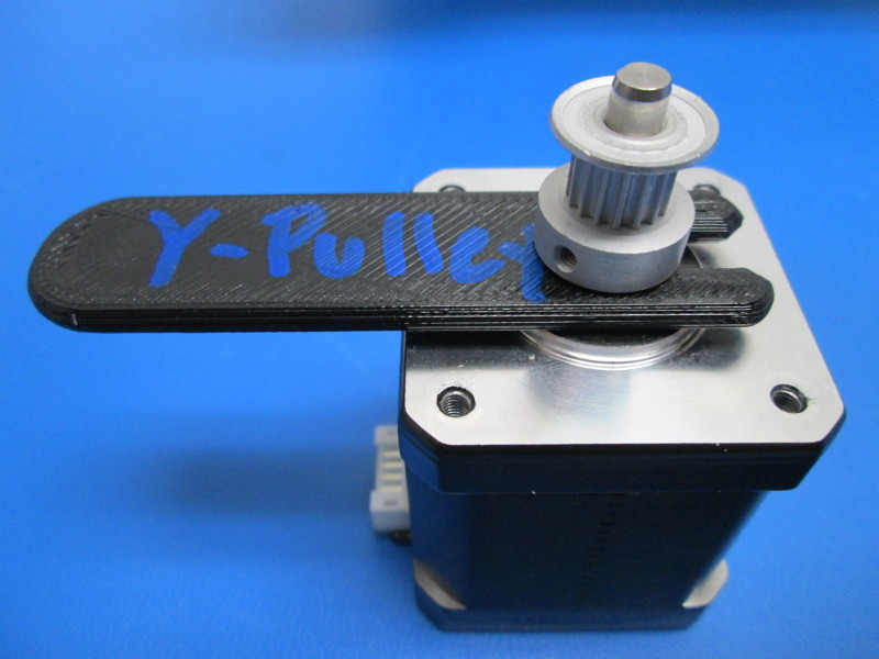
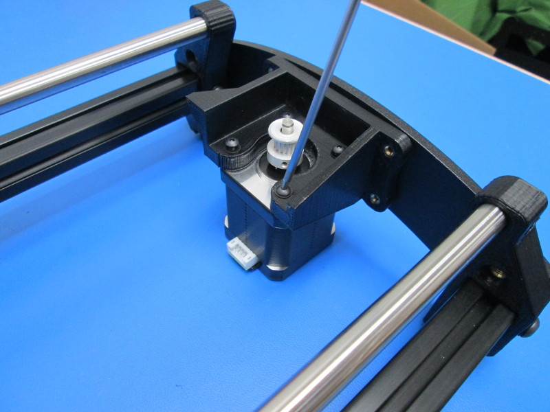
Set the height of the pulley on the Y motor shaft to (3.4 mm) as shown with the pulley height jig. Tighten the two (2) set screws 8in-lbst.
Attach the motor to the Motor Mount using four (4) M3x12 BHCS and four (4) M3 Black Washers; tighten to 5in-lbs.
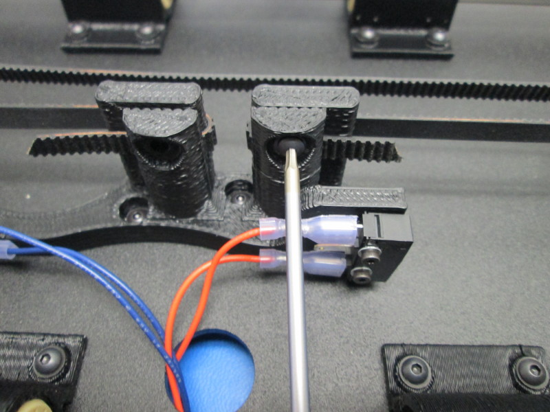
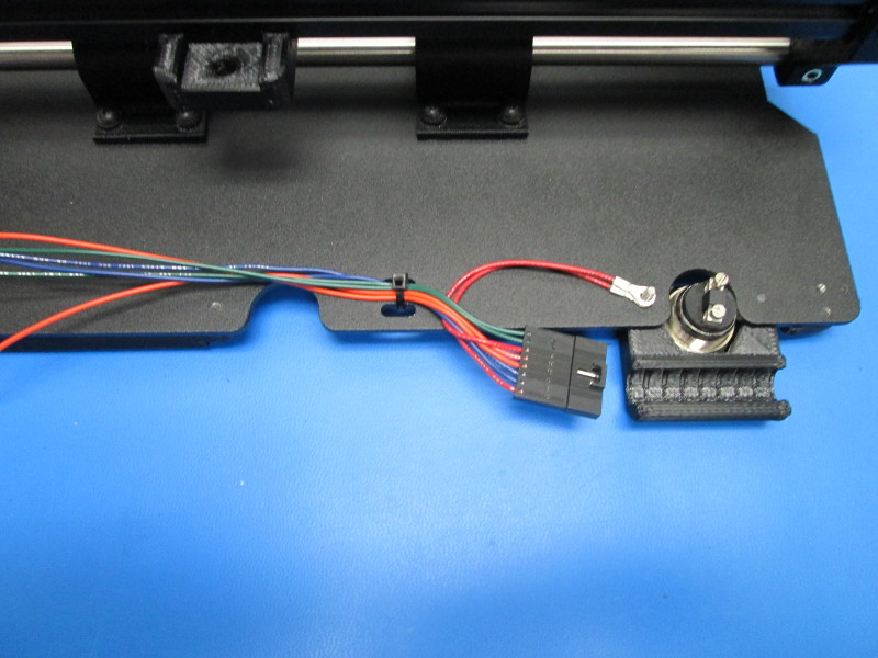
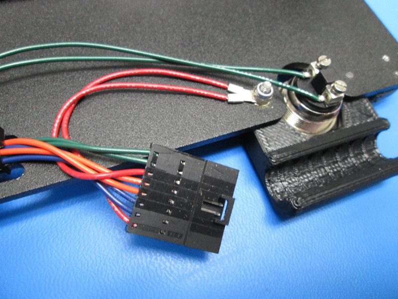
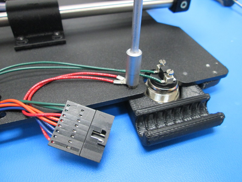
Install the Switch wire harness- Place a M3 star washer over the screw thread next to the Z switch mount, place the two (2) red wire, secure in place with an M3 Nyloc nut. Tighten the nut until the ring terminals are free of any movement. Make sure the M3 star washer is under the terminal rings at the end of the red wires.
A 2mm driver will likely be required to hold the Z min mount screw head (this serves as the ground post) as the Nyloc nut is secured. Both the Z min switch mount and the Nyloc must be well secured.
Put the blue and orange pairs of wires through the hole in the bed plate and push the spade connectors onto the limit switches (the middle blade of the limit switches should be empty.) The orange pair goes on the switch that is on the short side of the belt mount, and the blue pair goes on the switch that is on the long side of the belt mount.
Put the green ferruled wires into the screw terminals on the momentary switch. The switch should be clocked so that the screw terminal block is perpendicular to the close edge of the bed plate. Tighten the screw terminals finger tight.
Use a tie wrap to secure the harness. The wires should have a nice radius at each bend to prevent premature wear.
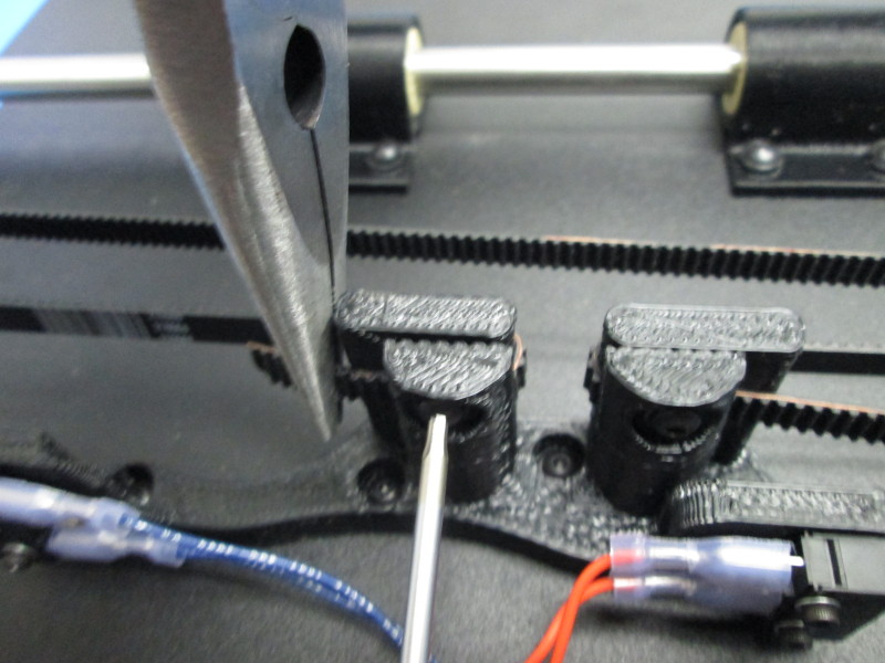
Snip one location on the drive belt to create an approximately 1m long non-continuous drive belt; Set one end of the drive belt with the smooth side oriented toward the Z switch into the belt clamp closest to the motor side; align the belt with the step feature in the clamp; secure the belt in the clamp with one (1) M3x12 BHCS and one (1) M3 black washer, tightened to 2in-lbs.
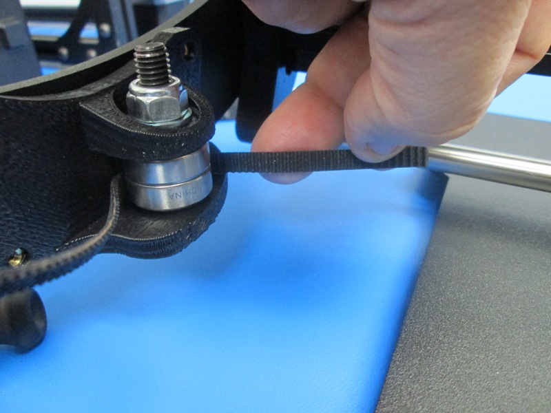
Without twisting the belt route the belt around the Y axis pulley so the belt teeth engage the pulley teeth then around the Y axis idler
Set the remaining end of the drive belt into the second belt clamp; align the belt with the step feature in the clamp; Tension the belt to approximately 23 to 27 Newtons; secure the belt in the clamp with one (1) M3x12 BHCS and one (1) M3 black washer, tightened to 2in-lbs; Trim excess belt back to no more than 10mm from the belt clamps
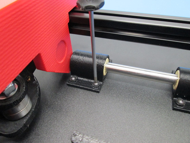
Install Ninjaflex feet as shown using one M3x8 BHCS and one M3 black washer per Y corner. Tighten to finger tight.