Open HardwareAssembly Instructions
Guides for installation and assembly of the LulzBot line of products made by FAME 3D LLC.
Guides for installation and assembly of the LulzBot line of products made by FAME 3D LLC.
Utilize OHAI for Hexagon Hot End to build a .50mm Hot End Assembly v2, for single
Parts to use:
1x- (PP-GP0208) Extruder Mount TAZ6
1x- (AS-HE0039) Gunnison Hotend assembly
1x- (PP-GP0186) Extruder body assembly
1x- (PP-MP0156) MOARstuder Mount Plate
2x- (HD-BT0039) M3x 12 SHCS
2x- M3 nut SS
1 each of 3 extruder cable assemblies (see next step for instructions)
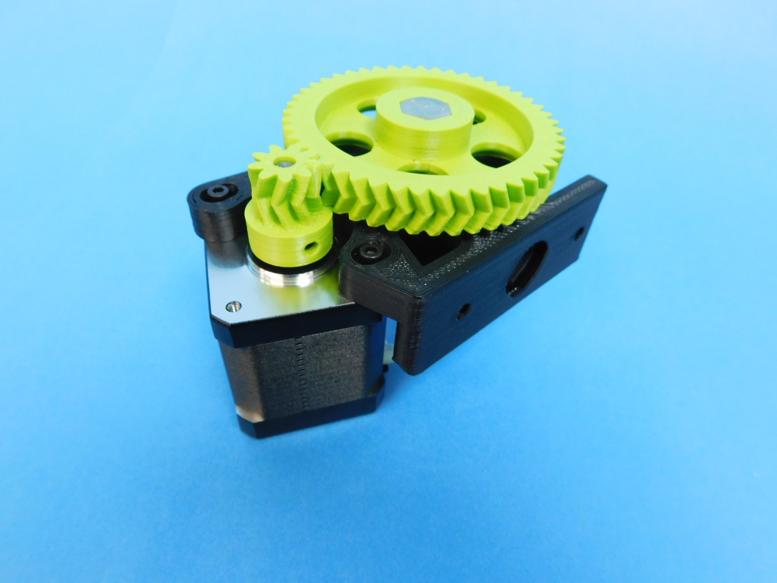
Utilize OHAI for Extruder Body sub-assembly to build a Extruder Body assembly (Herringbone gears will be Green).
TAZ6 wire/ cable assemblies used by the TAZ6 single extruder
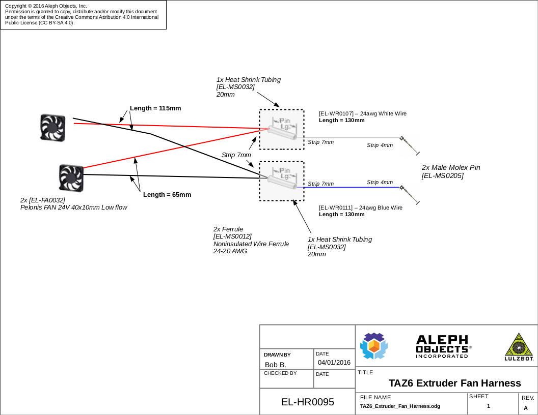
EL-HR0095 TAZ 6 Extruder Fan Harness is a standalone harness required to assemble an extruder
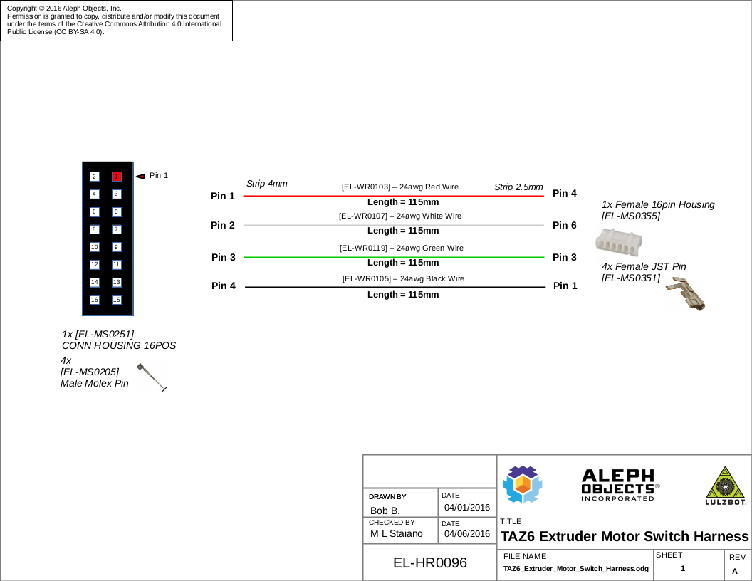
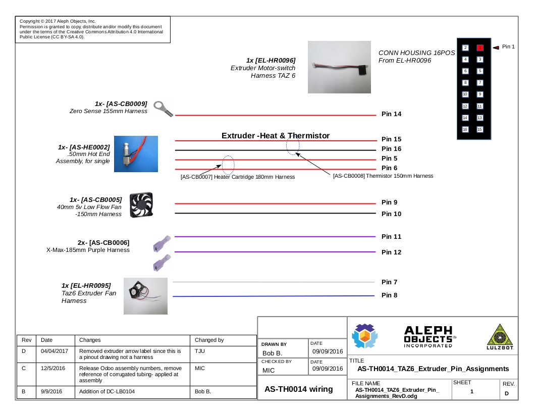
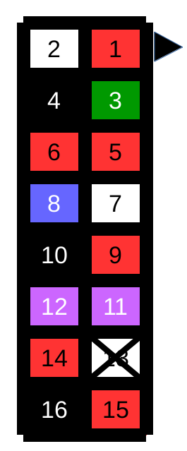
TAZ6_Extruder_Pin_Assignments drawing shows the wiring required in addition to EL-HR0096 & EL-HR0095 assemblies to complete wiring a TAZ 6 extruder
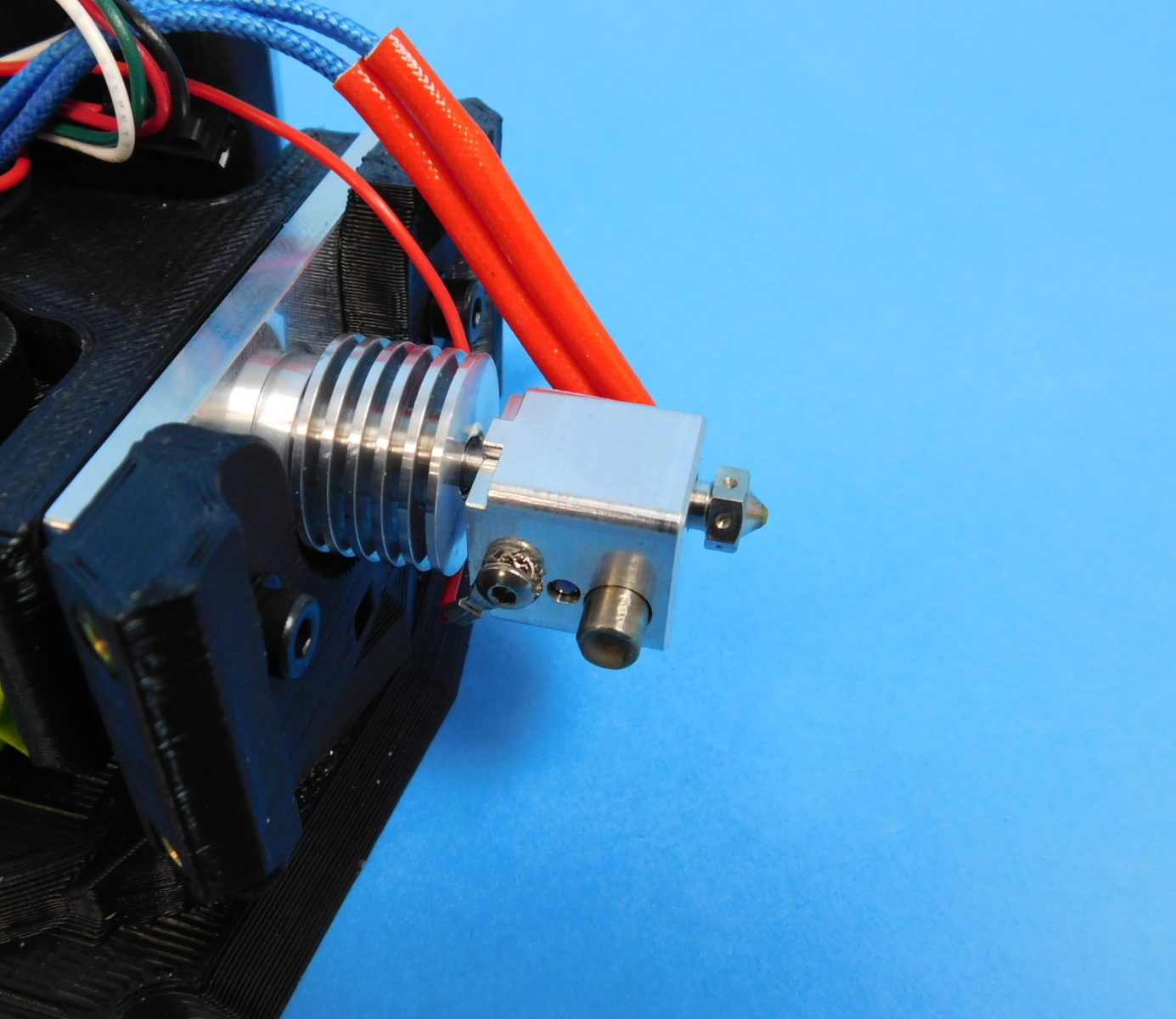
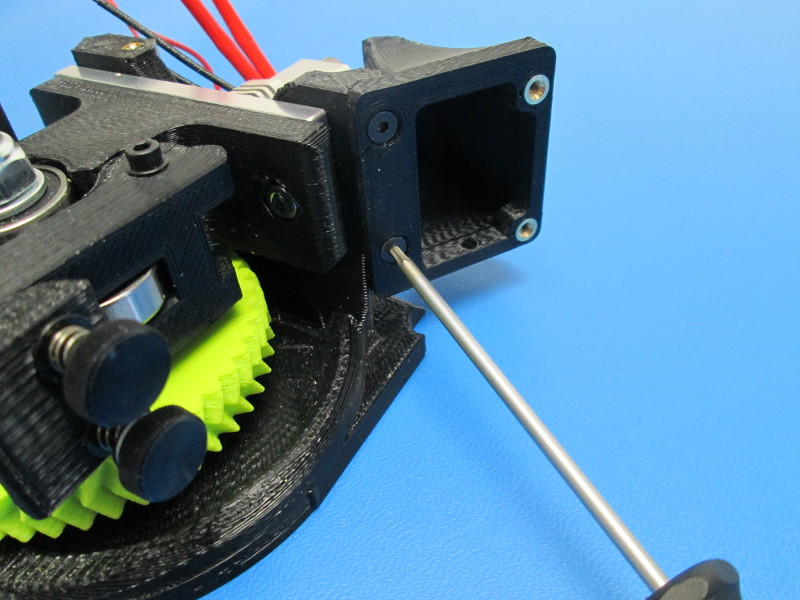
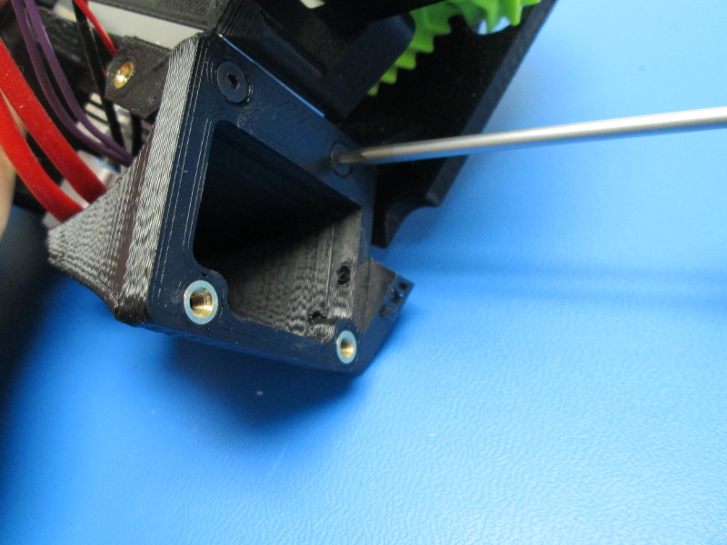
Attach the Hot End Assembly to the TAZ6 Extruder Mount
Connect the Hot End ground wire (220mm long) to the hot end. Route the ground wire behind the hot end, Plug ground wire into the 16pin connector that is attached to the motor at position 14. Use: 1x- 4-40 BHCS SS 1x- 4-40 star washer
Connect the Heater Cartridge and Thermistor to the 16 pin connector attached to the motor (Heater wires to positions 5 & 6; Thermistor black wire to position 16, red wire to position 15)
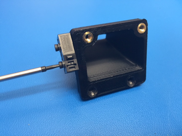
Attach X end stop switch to the Fan Duct, RIGHT (PP-GP0212). Note the Orientation of the switch, this is critical. Tighten screws to 3 in-lbs (~.35N-m) Use: 2x- M2 x 6 SHCS 2x- M2 SS washer
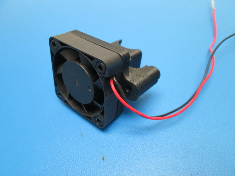
Prepare the heat sink fan and attach to the Hot End Heat Sink fan duct (PP-GP0232 ) with inserts already installed. Note orientation of fan. Use: 4x- M3x 12 SHCS tighten to 8 in-lbs (~.9N-m)
Attach the Left (PP-GP0211) and Right (PP-GP0212) fan ducts to the Extruder Mount TAZ6 Use: 2x- M3 x 12 FHS (for each duct), tighten to 8 in-lbs (~.9 N-m)
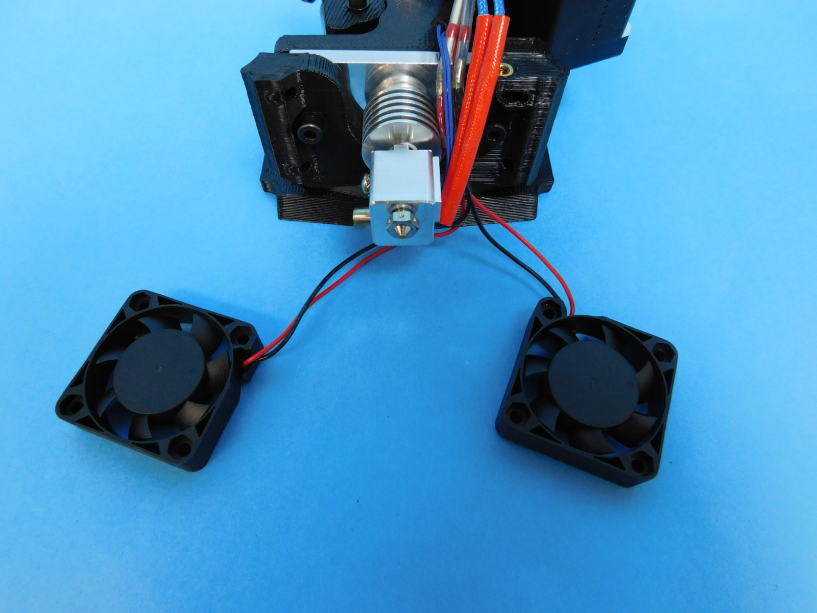
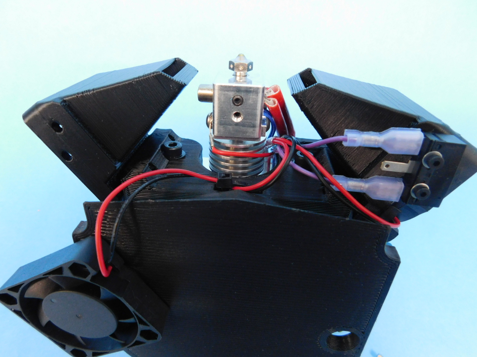
Prepare the Hotend dual fan sub-assembly Layout the assembly in front of the Extruder with the fan that has the longest wire cut length to the left of the extruder and the shortest to the right side of the extruder.
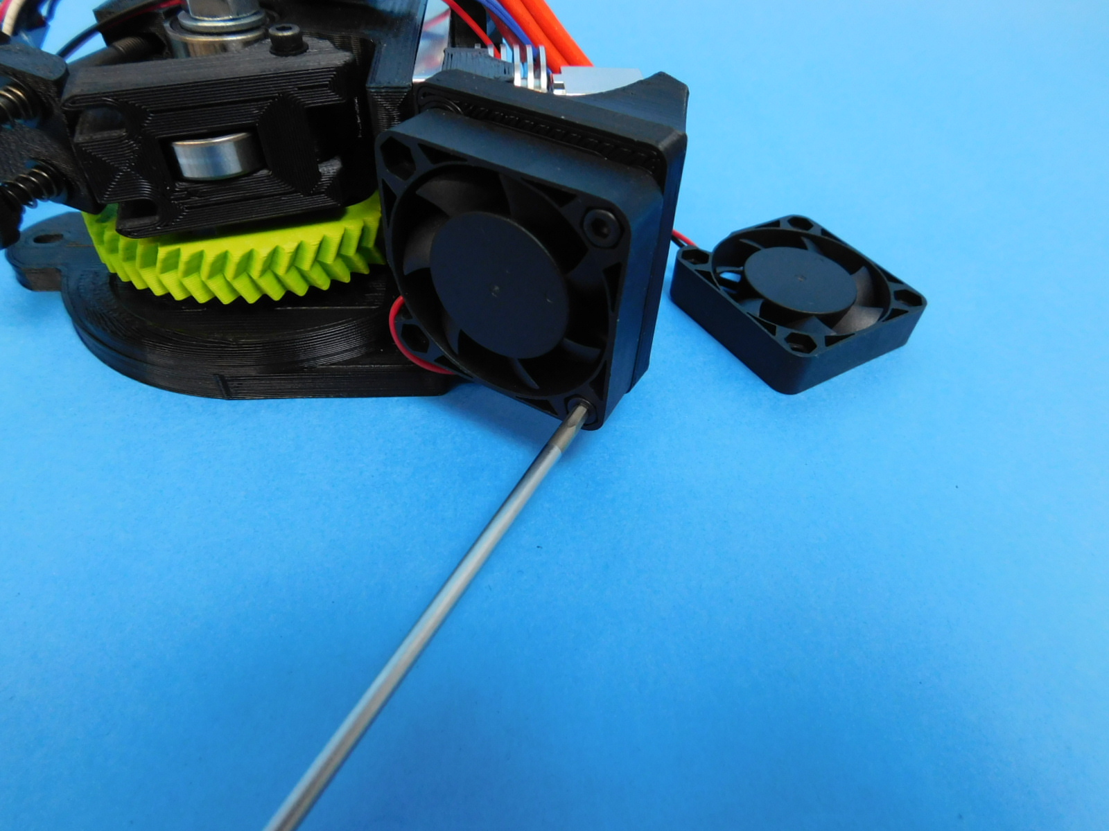
Attach the long fan to the Duct, Left. Note Orientation of the wires exiting the fan. Use: 2x- M3x 12 SHCS; tighten to 8 in-lbs (~.9 N-m)
Attach the short fan to the Duct, Right. Note Orientation of the wires exiting the fan. Use: 2x- M3x 12 SHCS; tighten to 8 in-lbs (~.9 N-m)
Route the long fan wire along the back of the mount, secure in place with a Ty wrap as shown, proper routing is critical
Connect Switch to the 16 pin connector at positions 11 & 12, connect to the switch terminals shown; route wires as shown Use: 2x- 190mm purple wire with terminals and Faston PIDGN connector
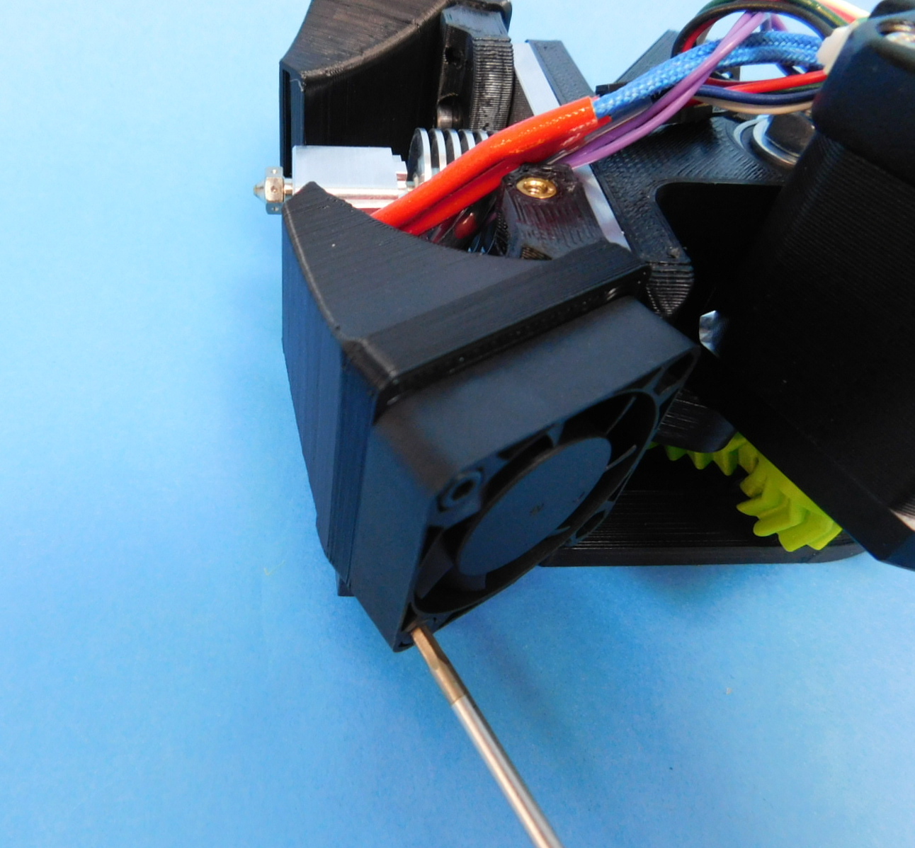
Attach Heat Sink Fan Duct to assembly Route wires into the duct channel as shown, secure duct to assembly Use: 1x- M3x 25 SHCS; 1x- M3 washer; ; tighten to 8 in-lbs (~.9 N-m)
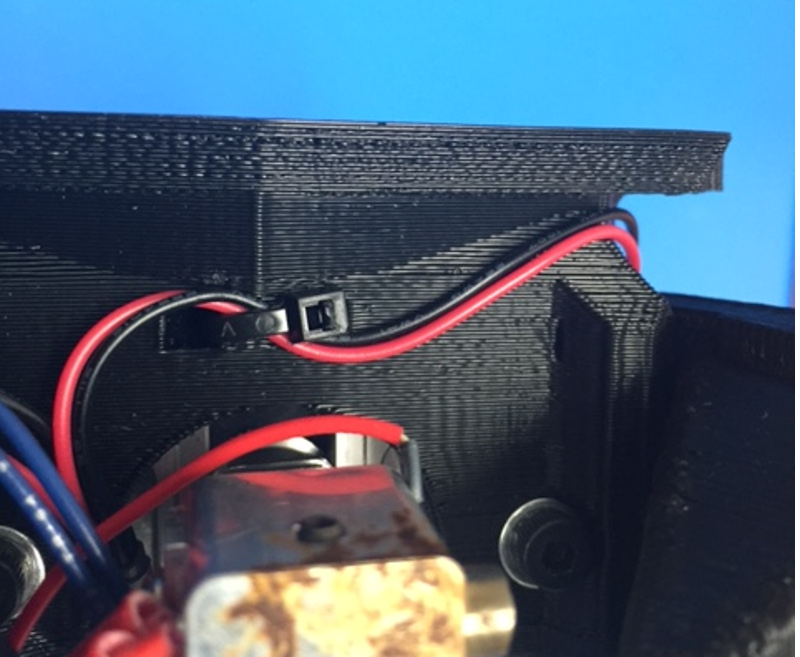
Connect Switch to the 16 pin connector at position 8 for the blue wire and position 7 for the white wire.


140) Attach Heat Sink fan to 16 position connector at position 10 for the black wire and position 9 for the red wire. Wrap 3/4” panduit (100mm length) around wires starting at the bottom of the connector and completing as far down the wire bundle as possible Secure the panduit to the wire bundle with one Ty Wrap; Position the Ty Wrap approximately where shown
150) Apply the Connect Up label onto the Pin 1 side of the connector nearest the pins extending from the connector

