Open HardwareAssembly Instructions
Guides for installation and assembly of the LulzBot line of products made by FAME 3D LLC.
Guides for installation and assembly of the LulzBot line of products made by FAME 3D LLC.
WARNING:
At Aleph Objects, Inc. we respect your freedom to modify your LulzBot® 3D printer. Any modifications or attempted repairs that cause damage are not covered under the Warranty.
Questions? Contact Technical Support by emailing Support@LulzBot.com, or by calling +1-970-377-1111.
Begin by ensuring the printer is powered off and disconnected from the power supply.
To perform this upgrade, you will need a P1 Phillips screwdriver, a 2.5mm hex driver, a pair of clippers, and your LulzBot TAZ 4 or 5 3D Printer.
You will also need one LulzBot TAZ 4-5 Complete Heat Bed Harness.

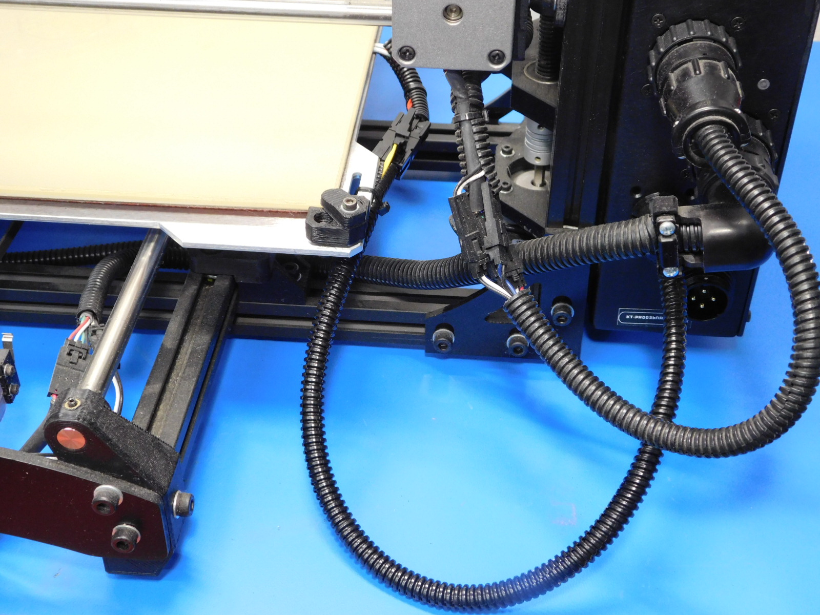
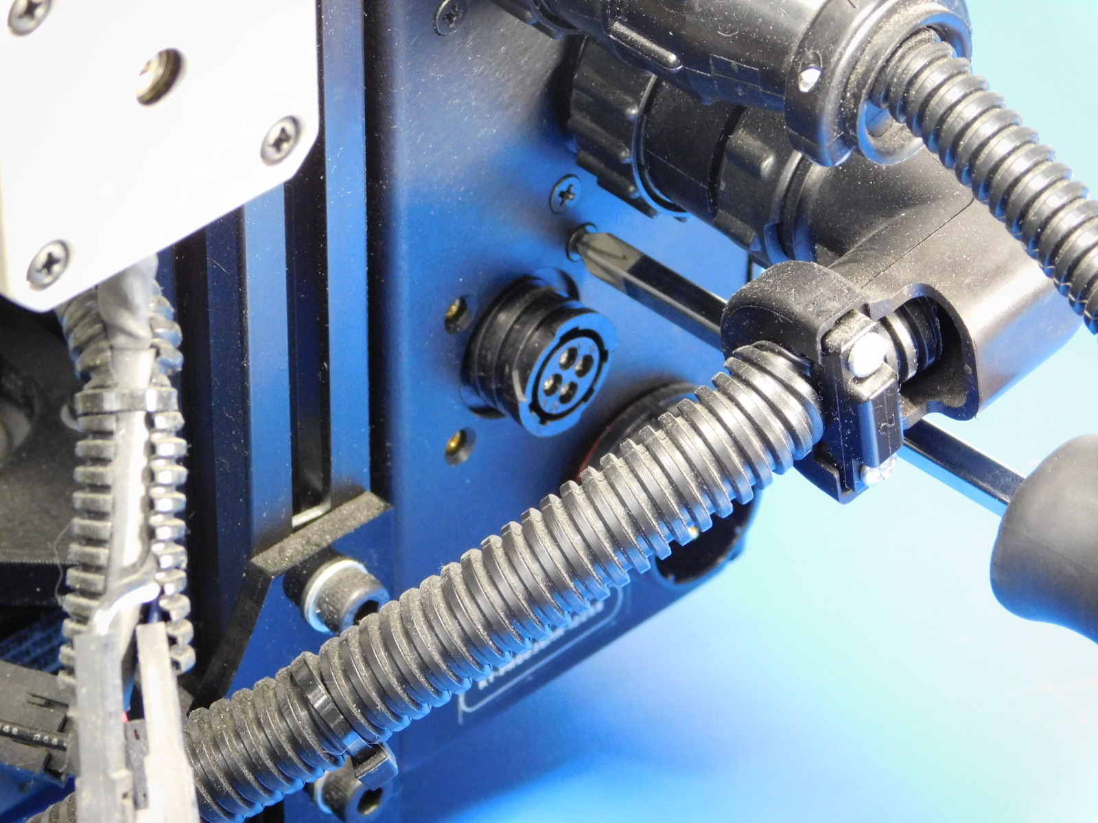
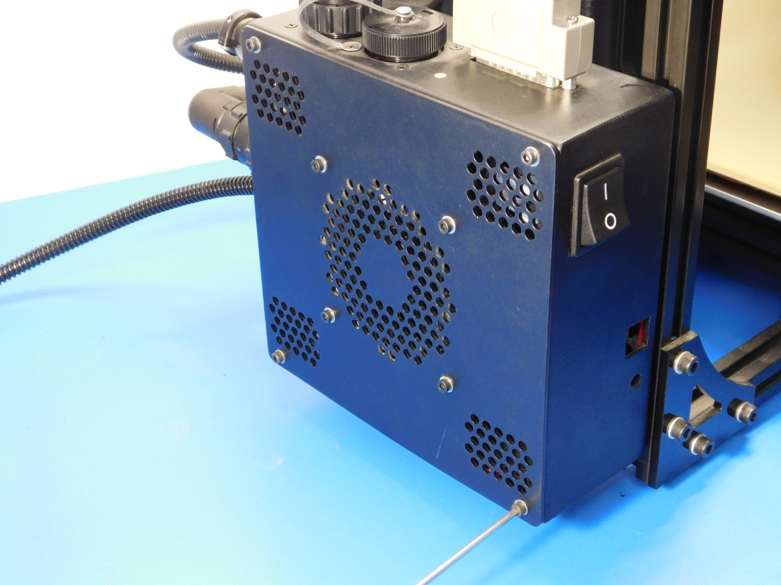
Turn the printer around so that the back side of the machine is facing you.
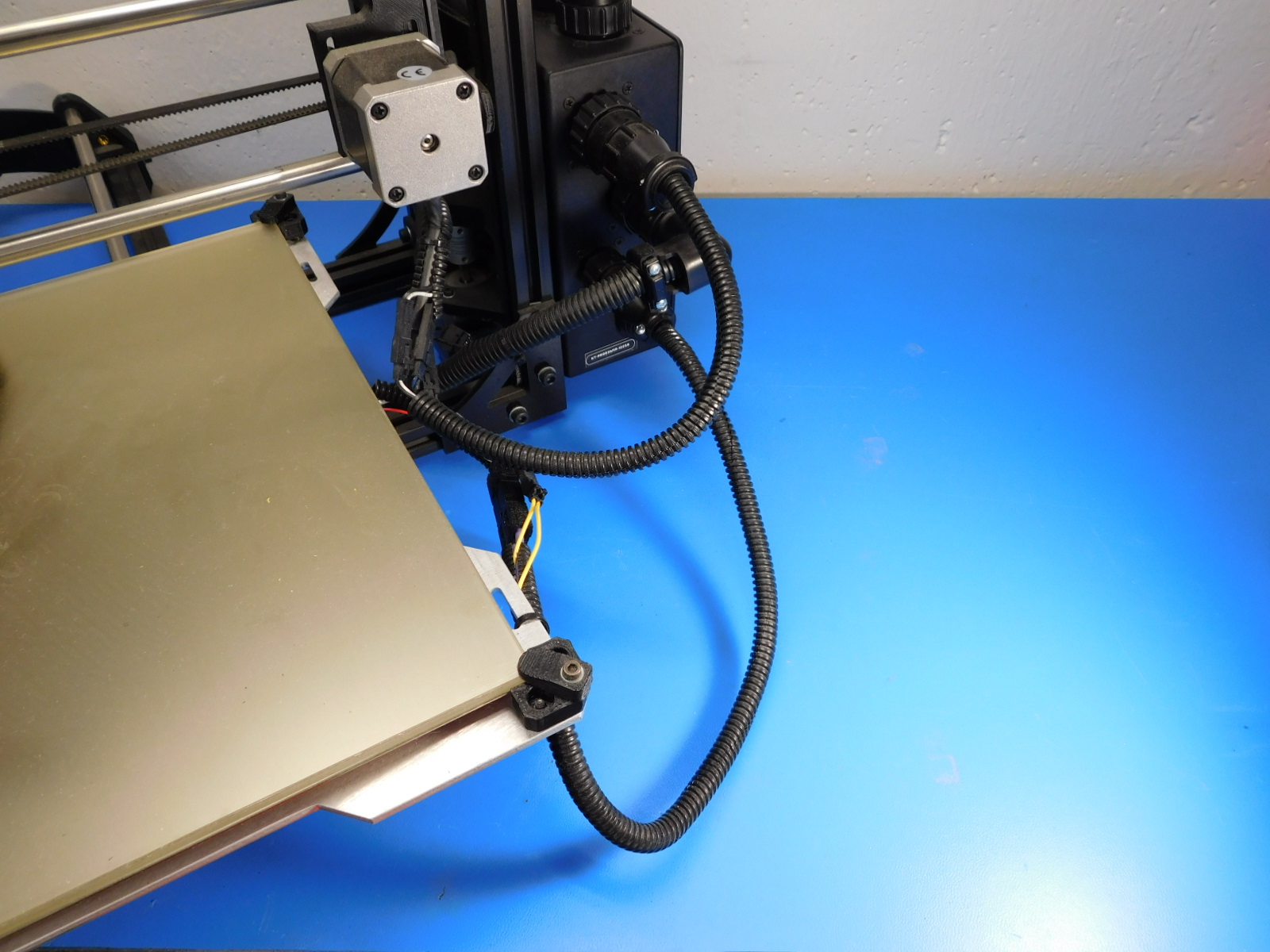
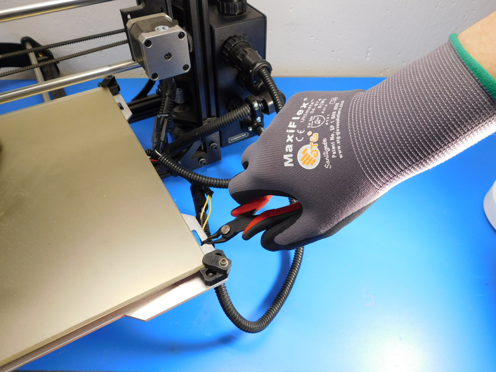
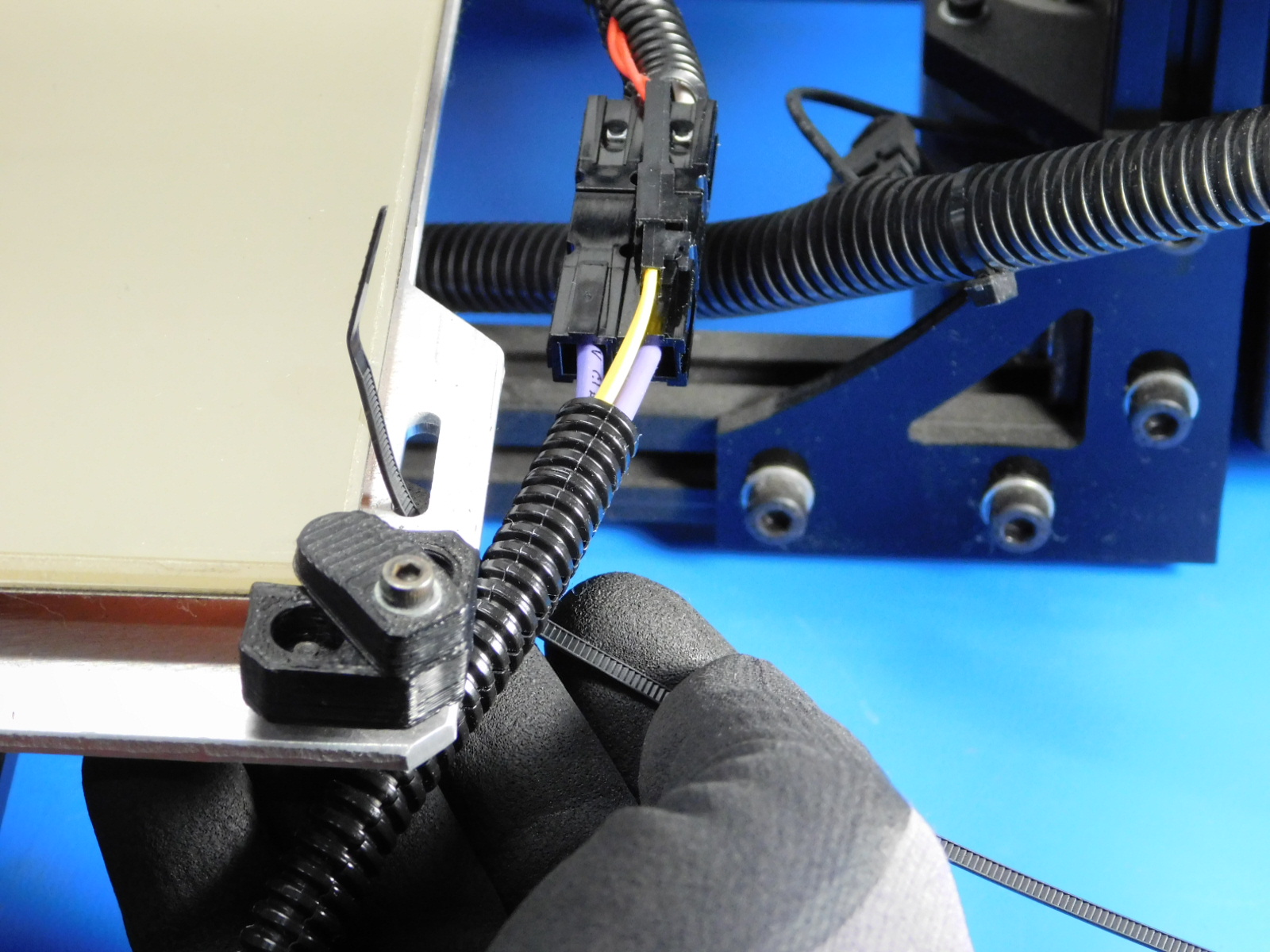
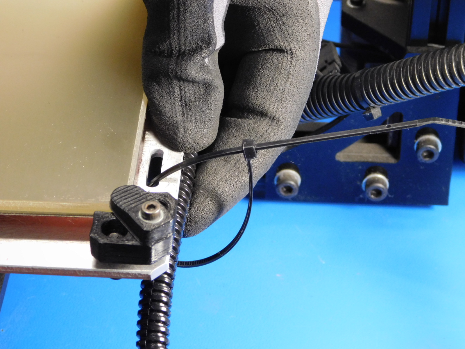
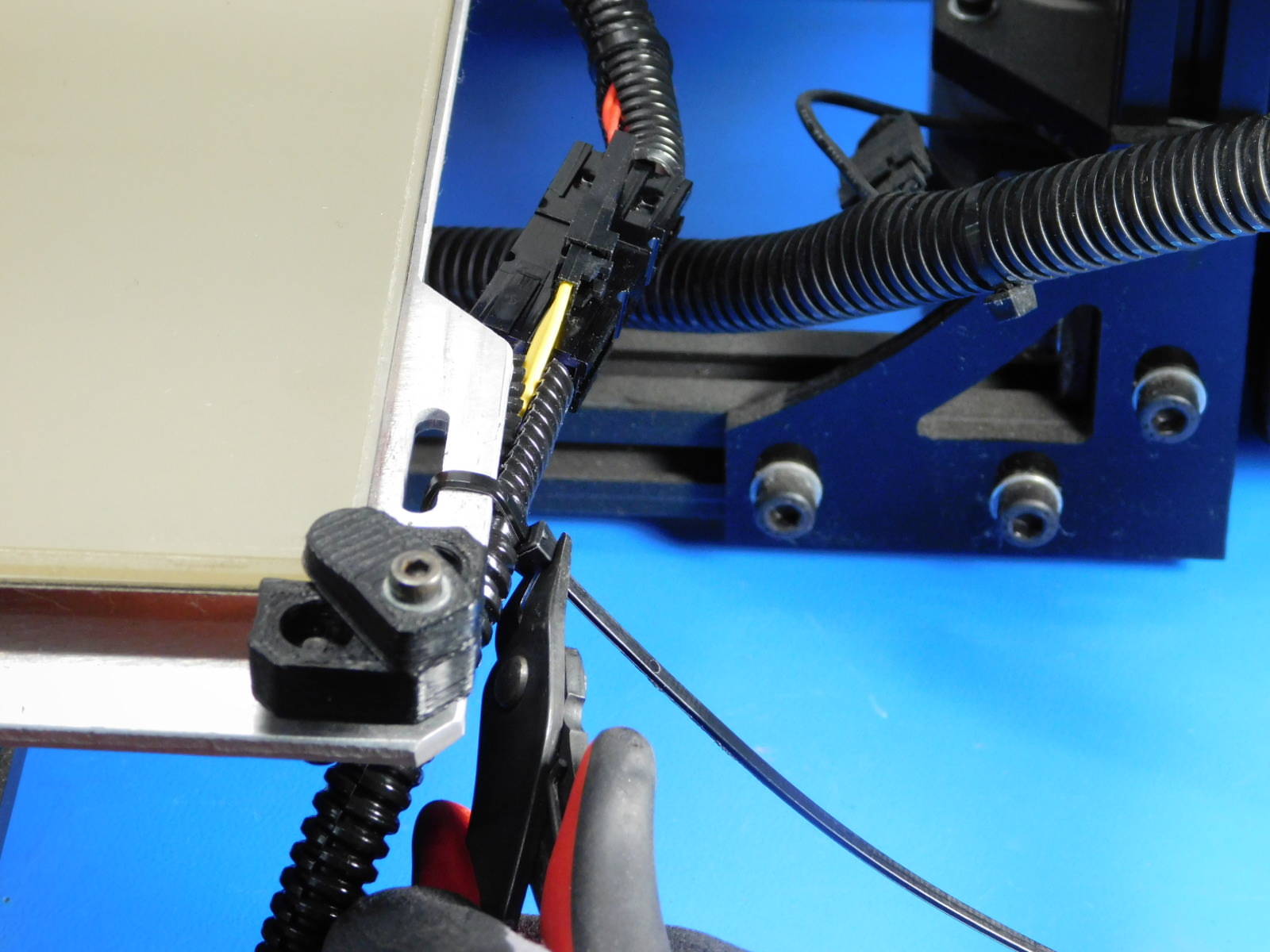
Using clippers, remove the zip tie securing the external bed harness to the bed plate.
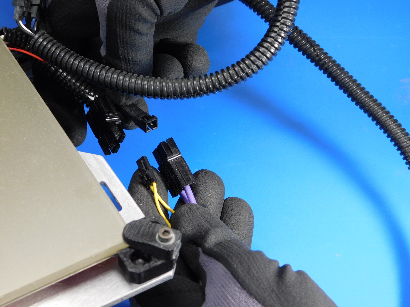
Disconnect both the bed power and bed thermistor connections at the bed.
Disconnect the external bed harness from the control box by twisting the locking ring counter-clockwise.

Using the P1 Phillips screwdriver, remove all four screws securing the internal bed harness to the control box enclosure.

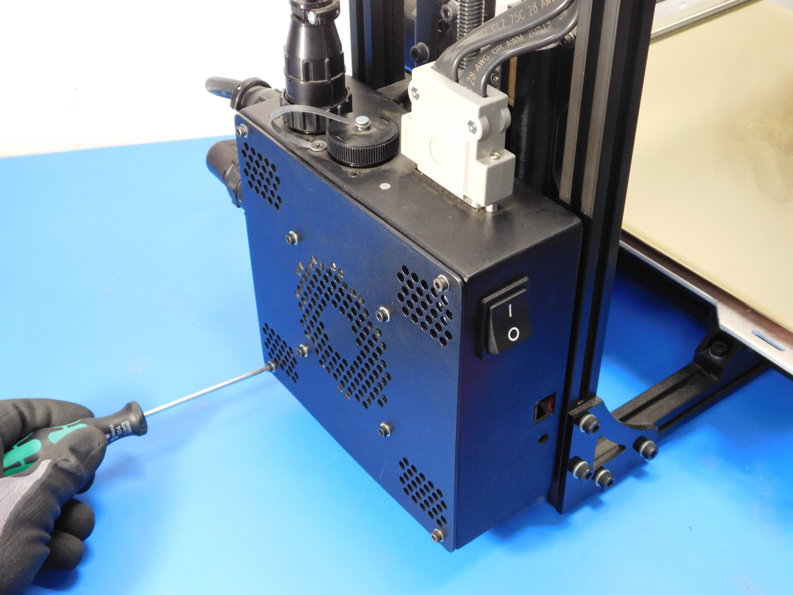
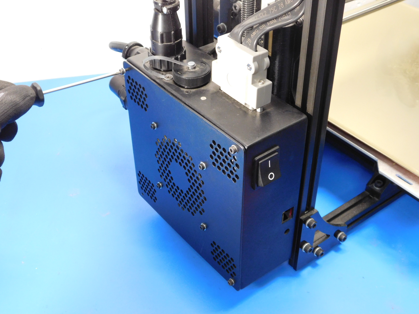
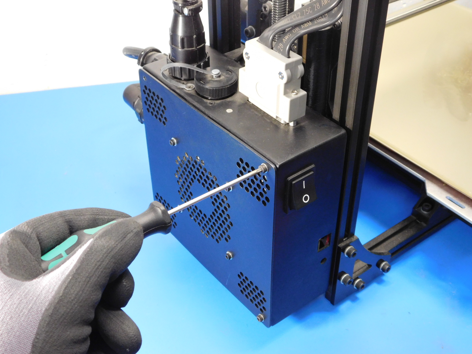
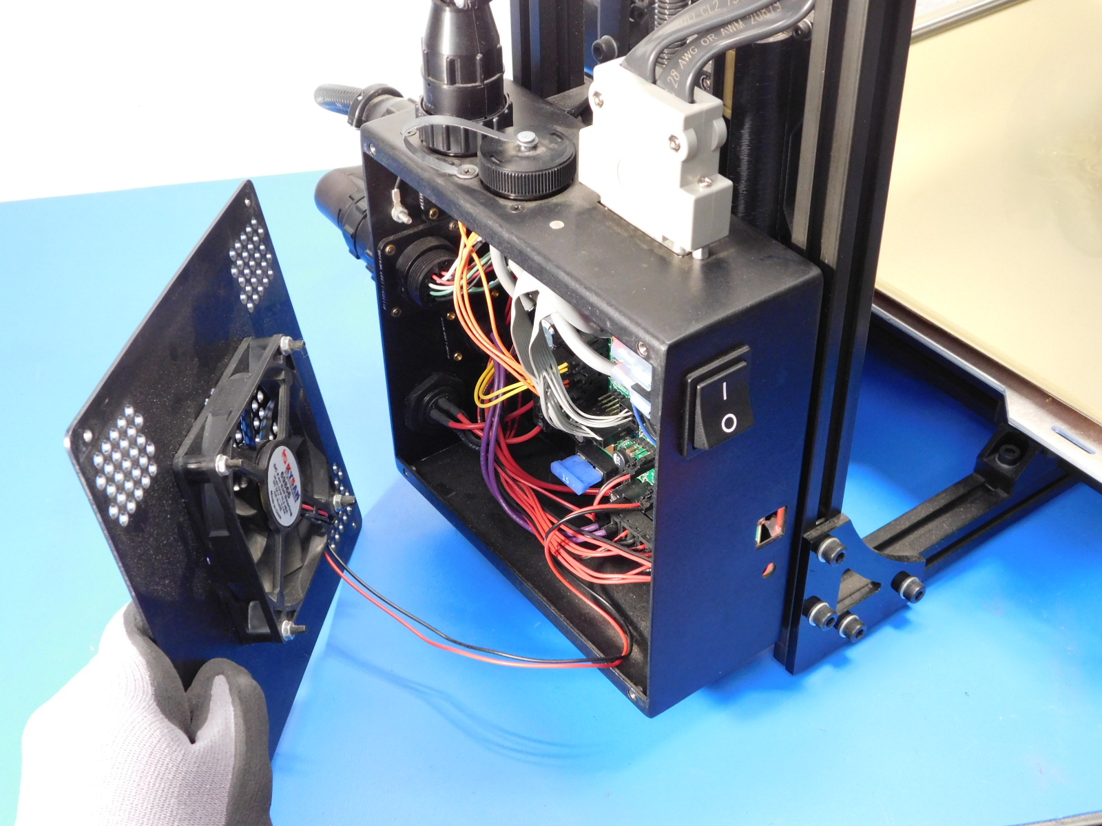
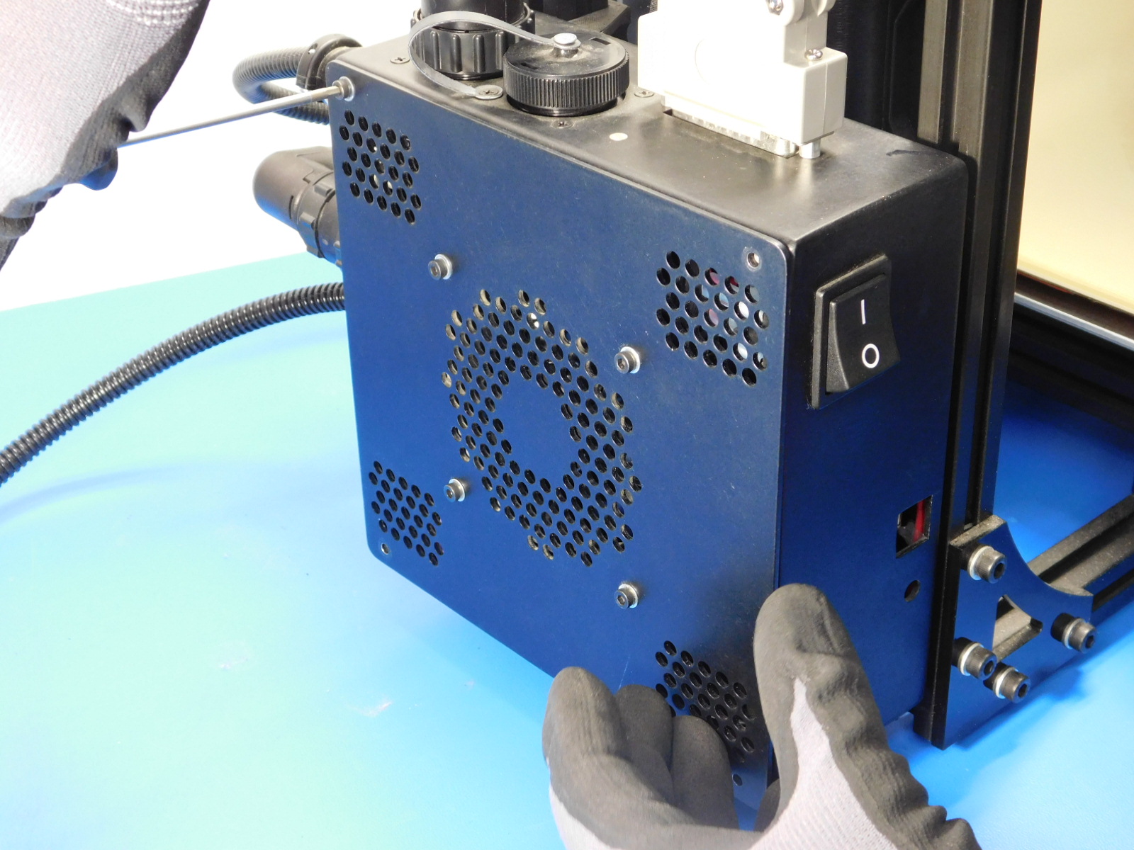
Rotate the printer so that the machine's left side is facing you.
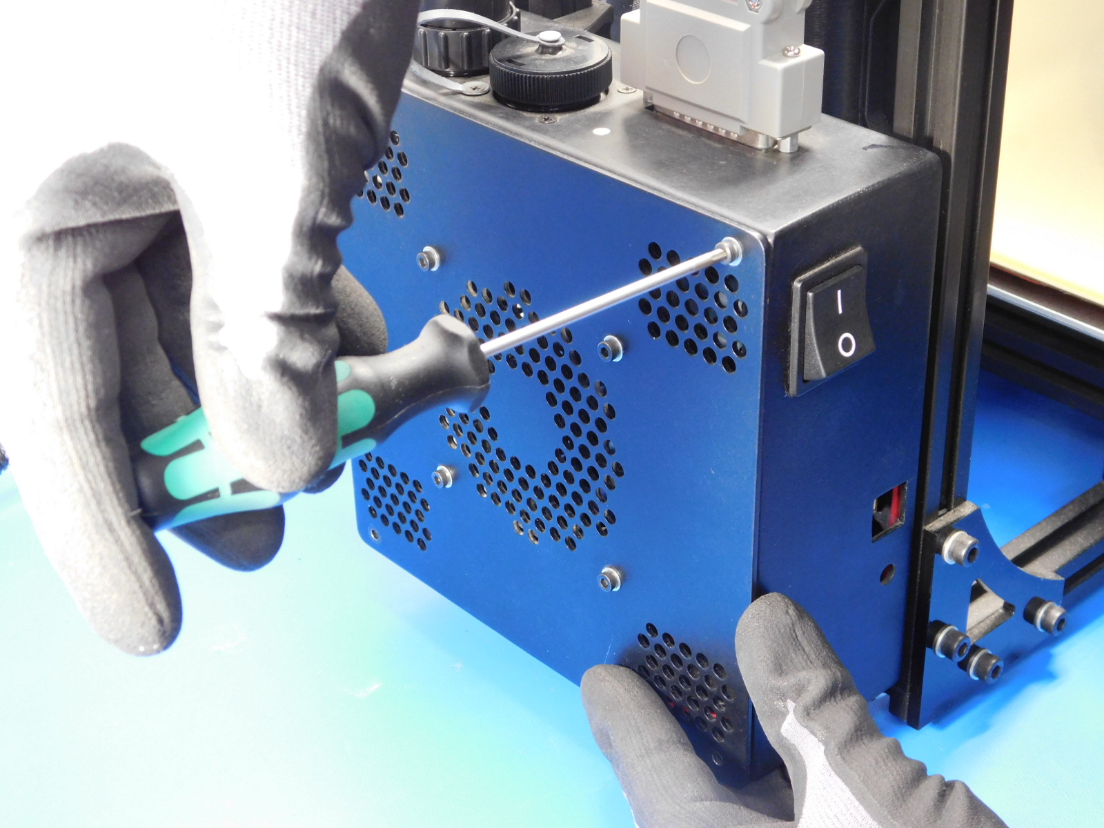
Using the 2.5mm hex driver, remove all four M3x12 fasteners securing the control box cover to the control box.
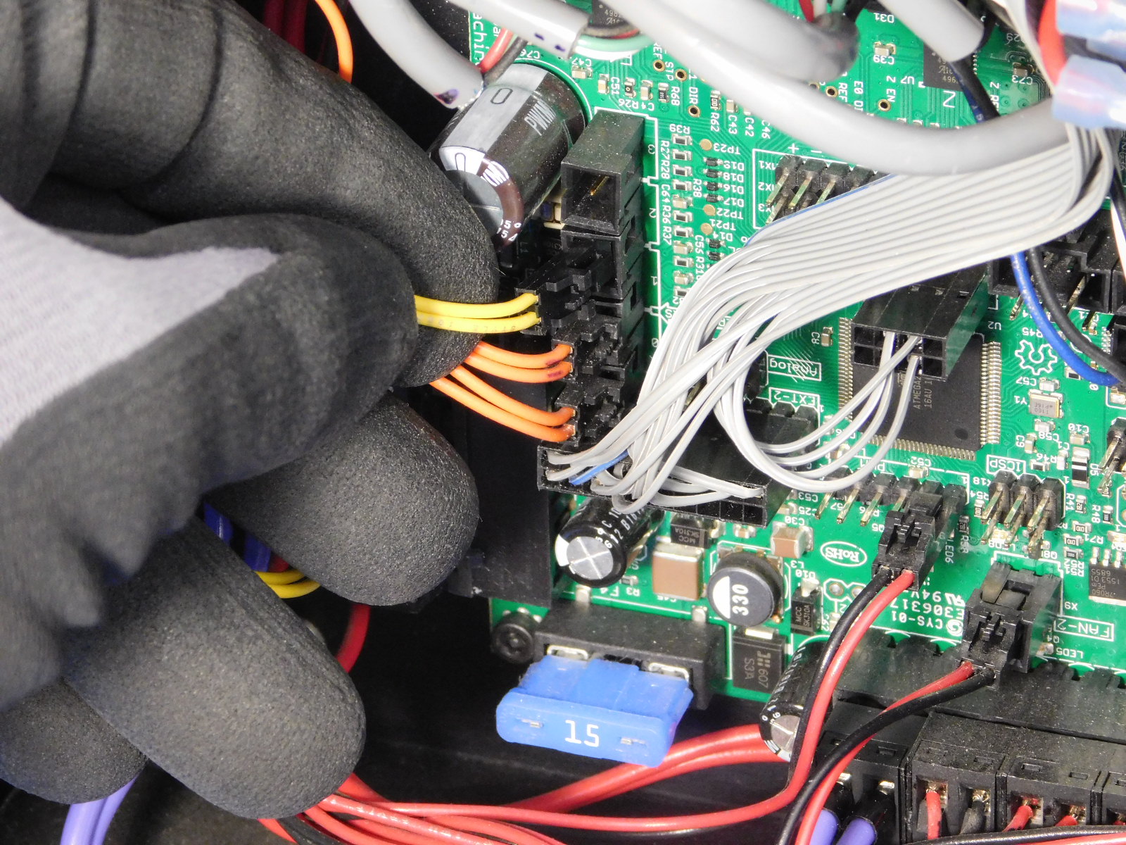
The control box case fan does not need to be disconnected from the RAMBo.

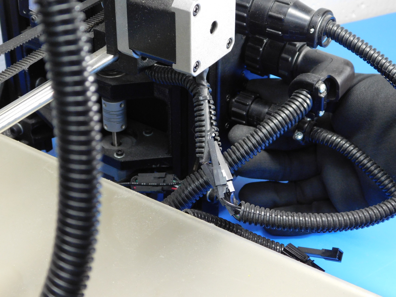
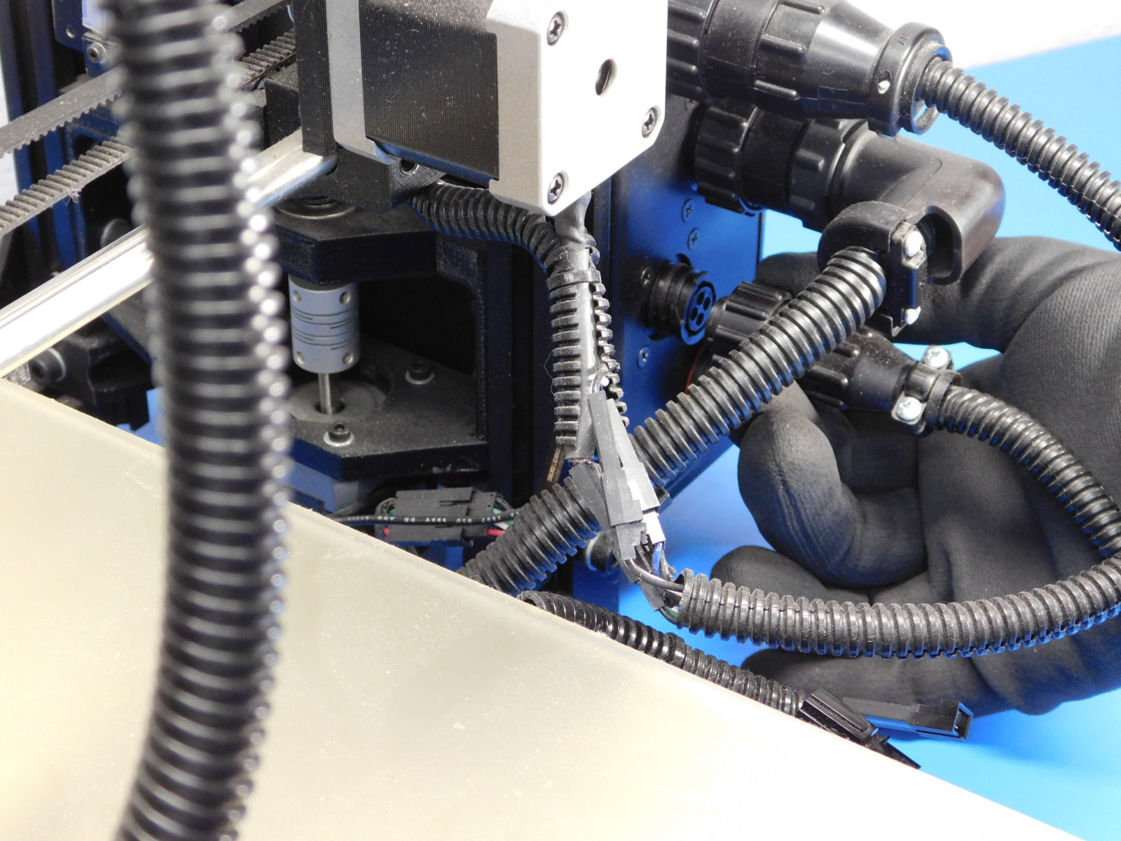
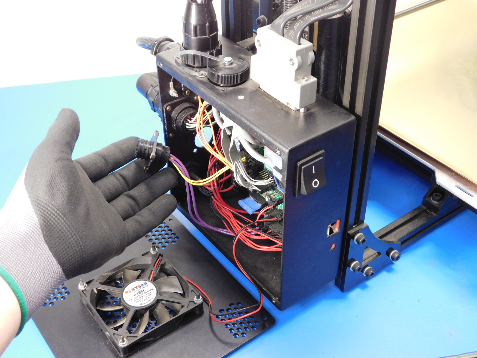
Pull the internal bed harness out of the hole in the control box exterior.
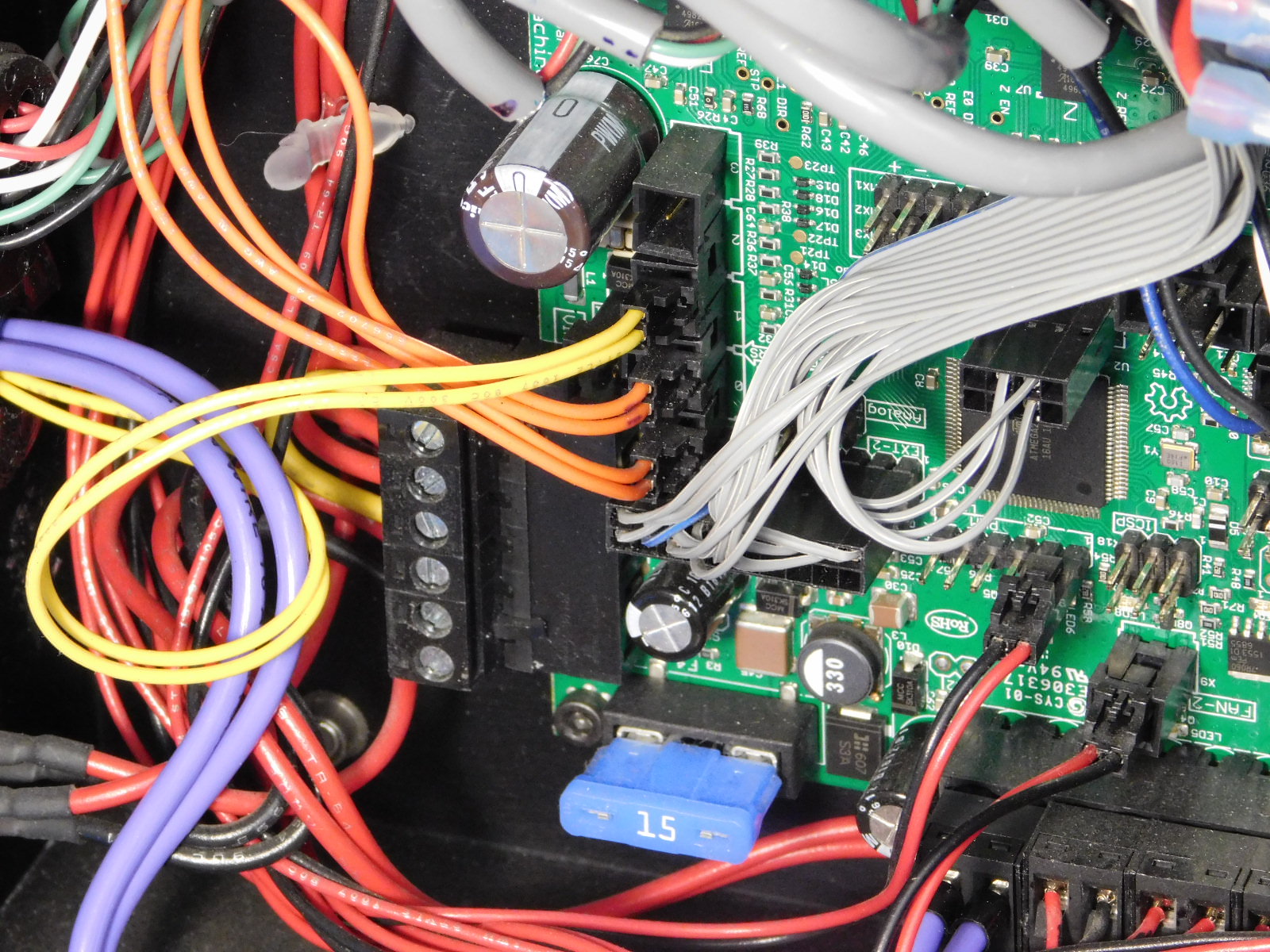
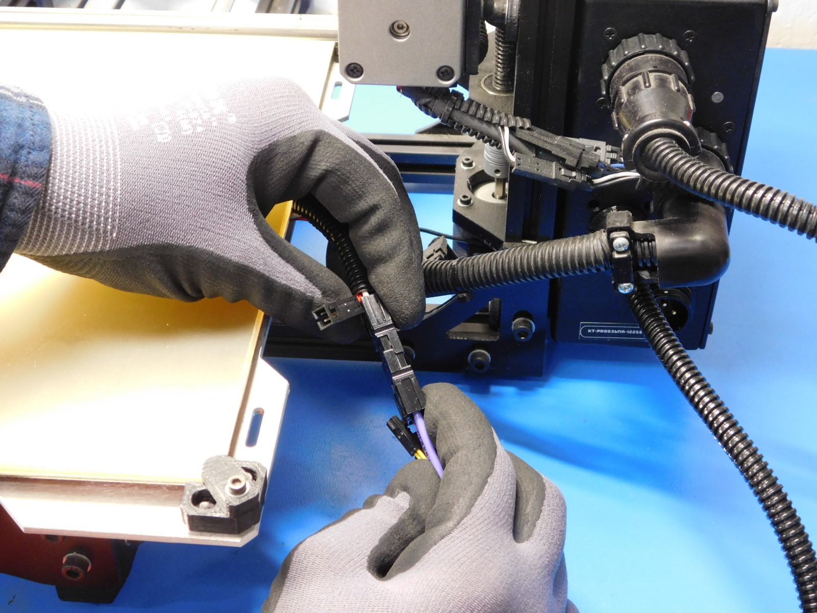
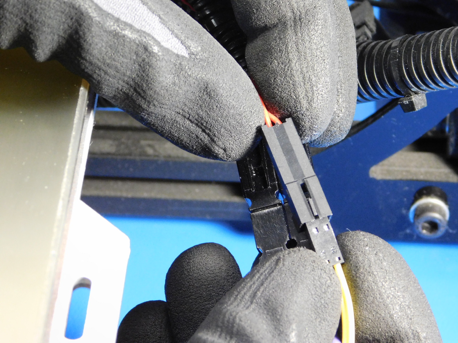
Use your thumb to press the clip on the bed thermistor connector (double yellow) and disconnect it.
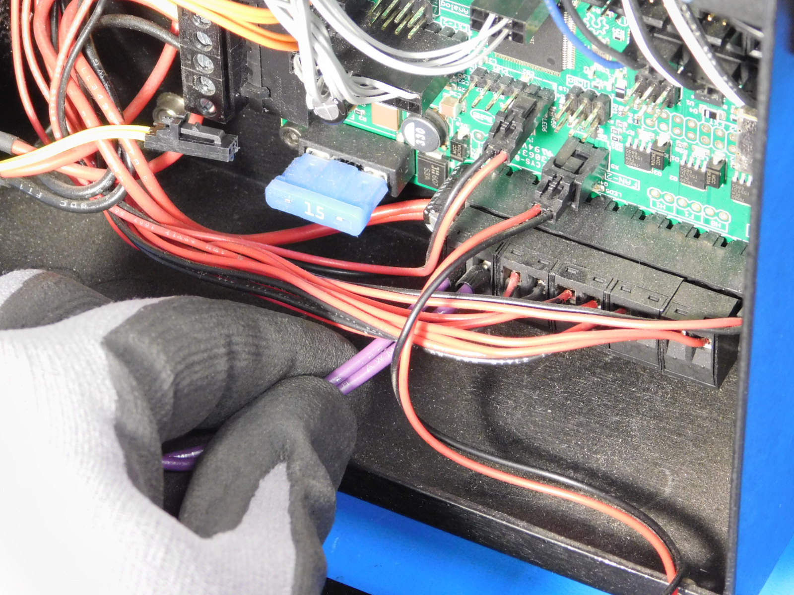
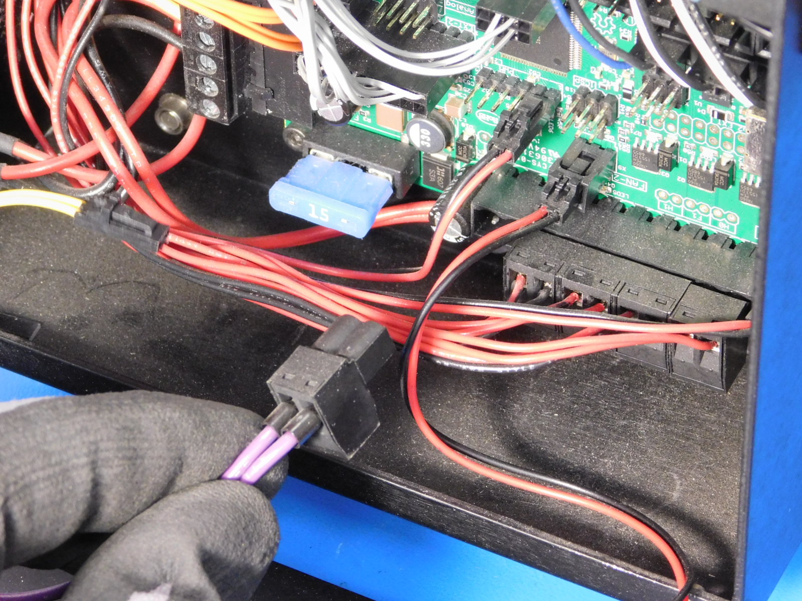
Carefully pull on the bed power connector (double purple) and disconnect it.
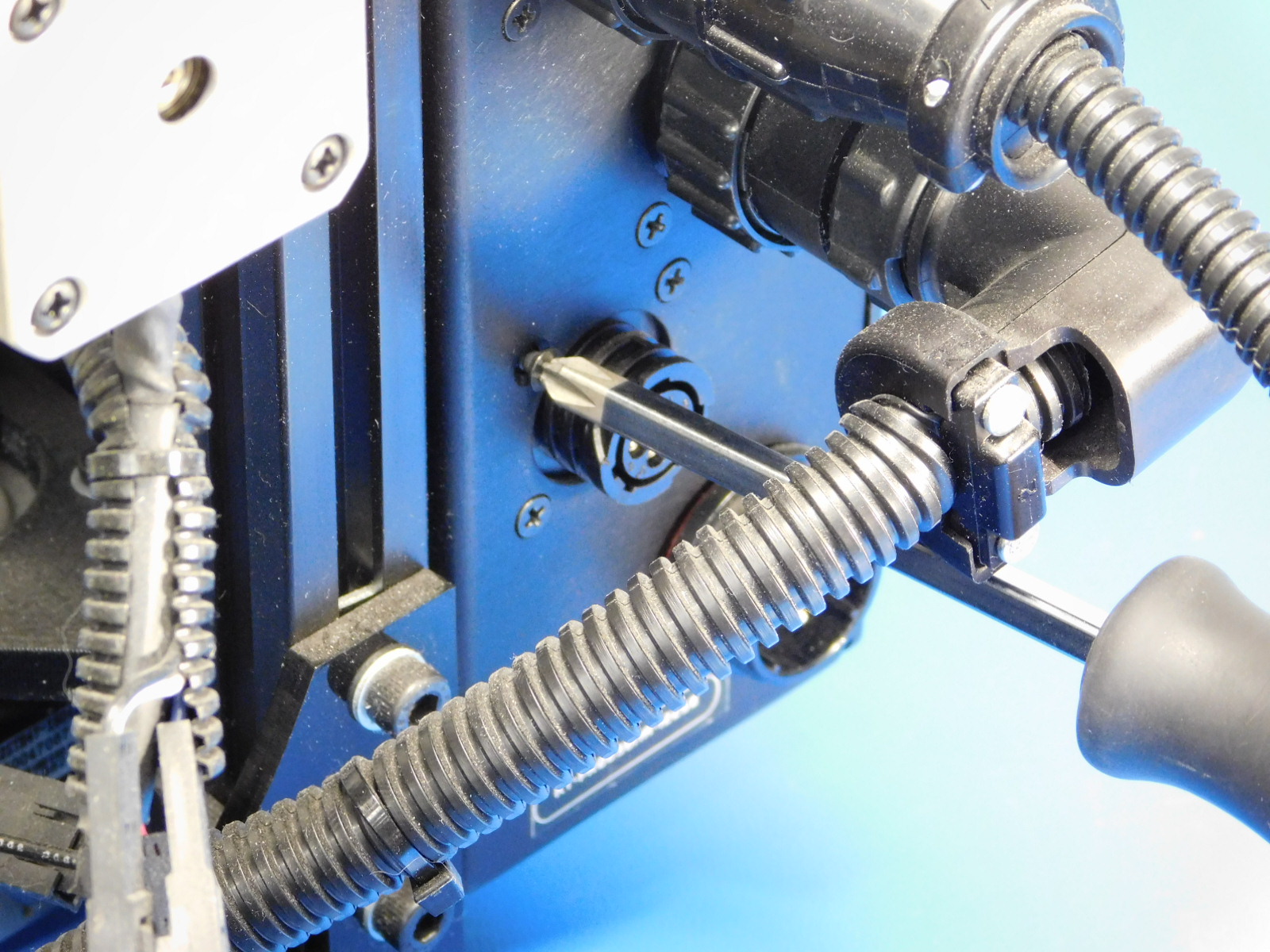
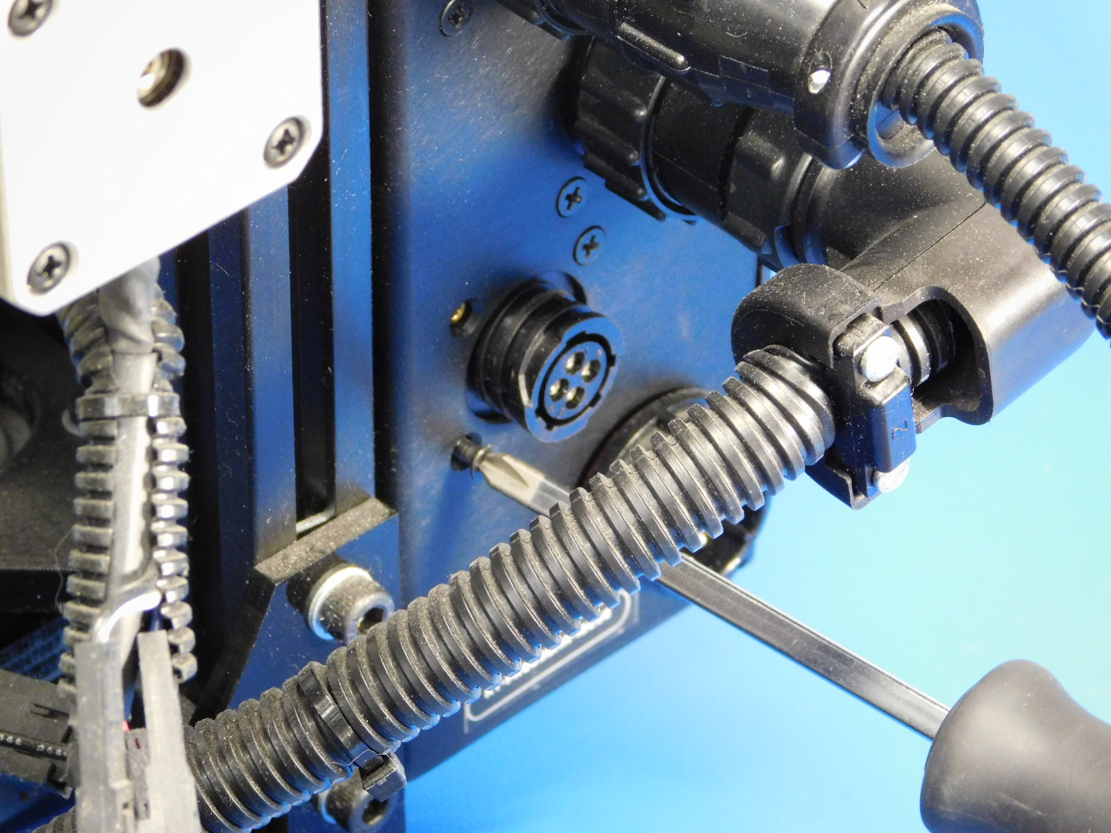
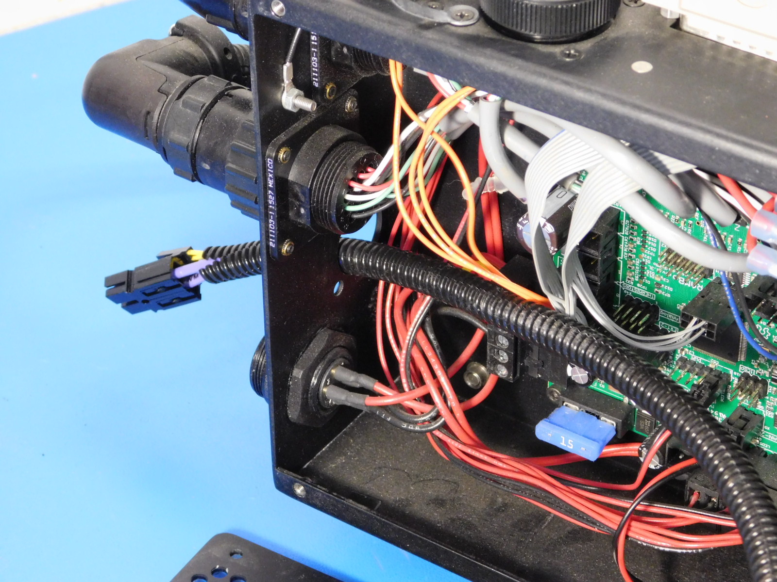
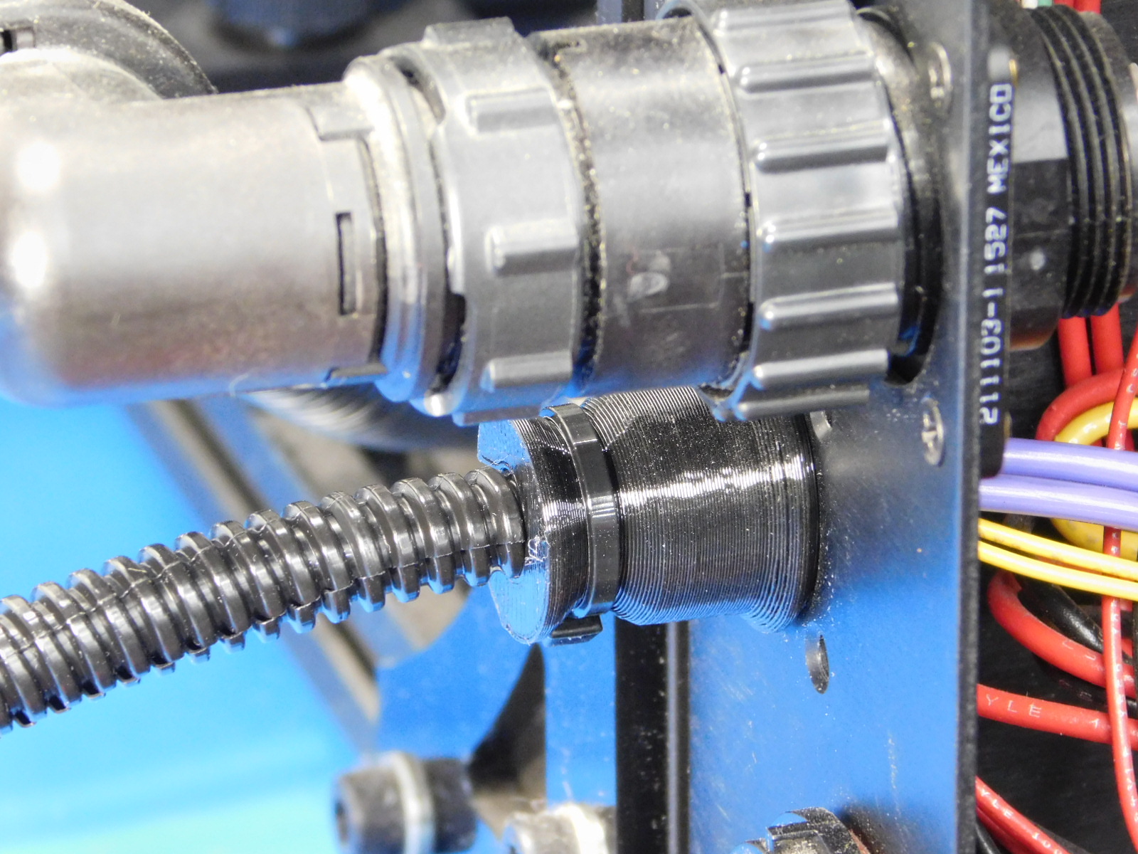
Begin by feeding the //bed side// of the new heat bed harness through the control box exterior from the inside, utilizing the hole that the old bed harness was removed from.
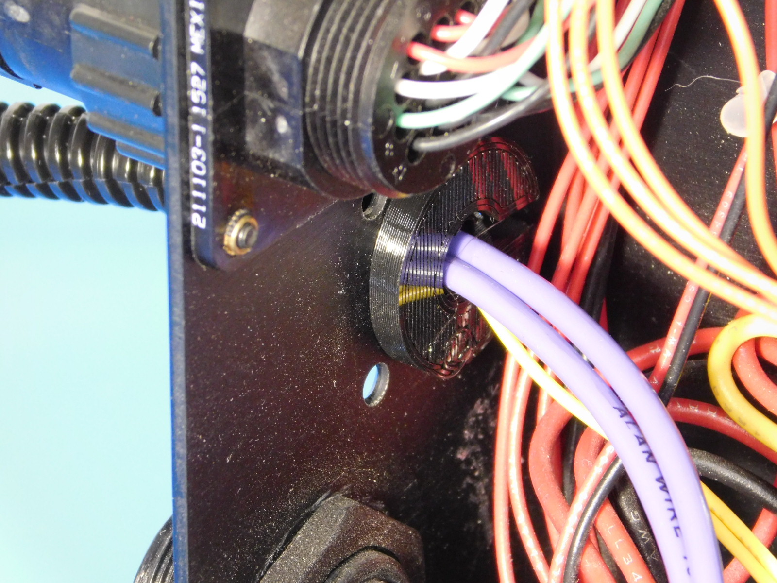
The bed side of the harness is the side with the Anderson PowerPole Connector; see photo.
Continue feeding the harness through the hole until you reach the printed NinjaFlex Strain relief.
Firmly press the printed strain relief into the hole in the control box exterior until it meets with the flange of the strain relief as shown.


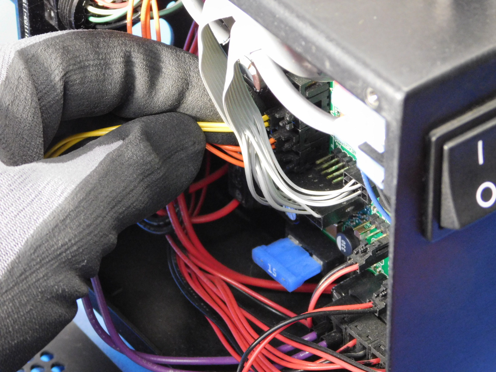
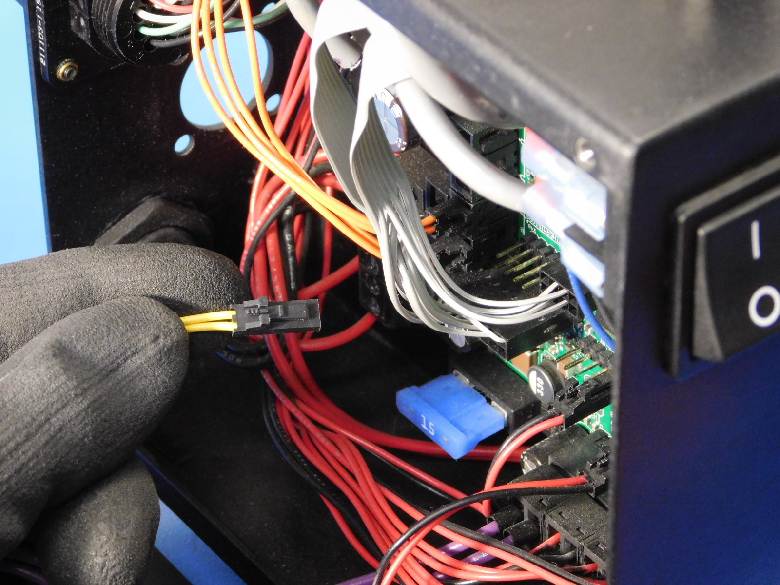
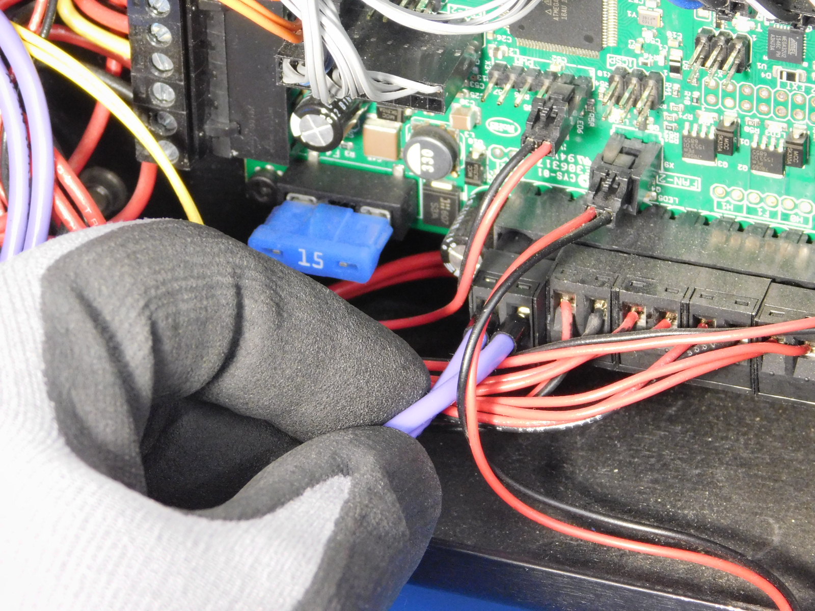
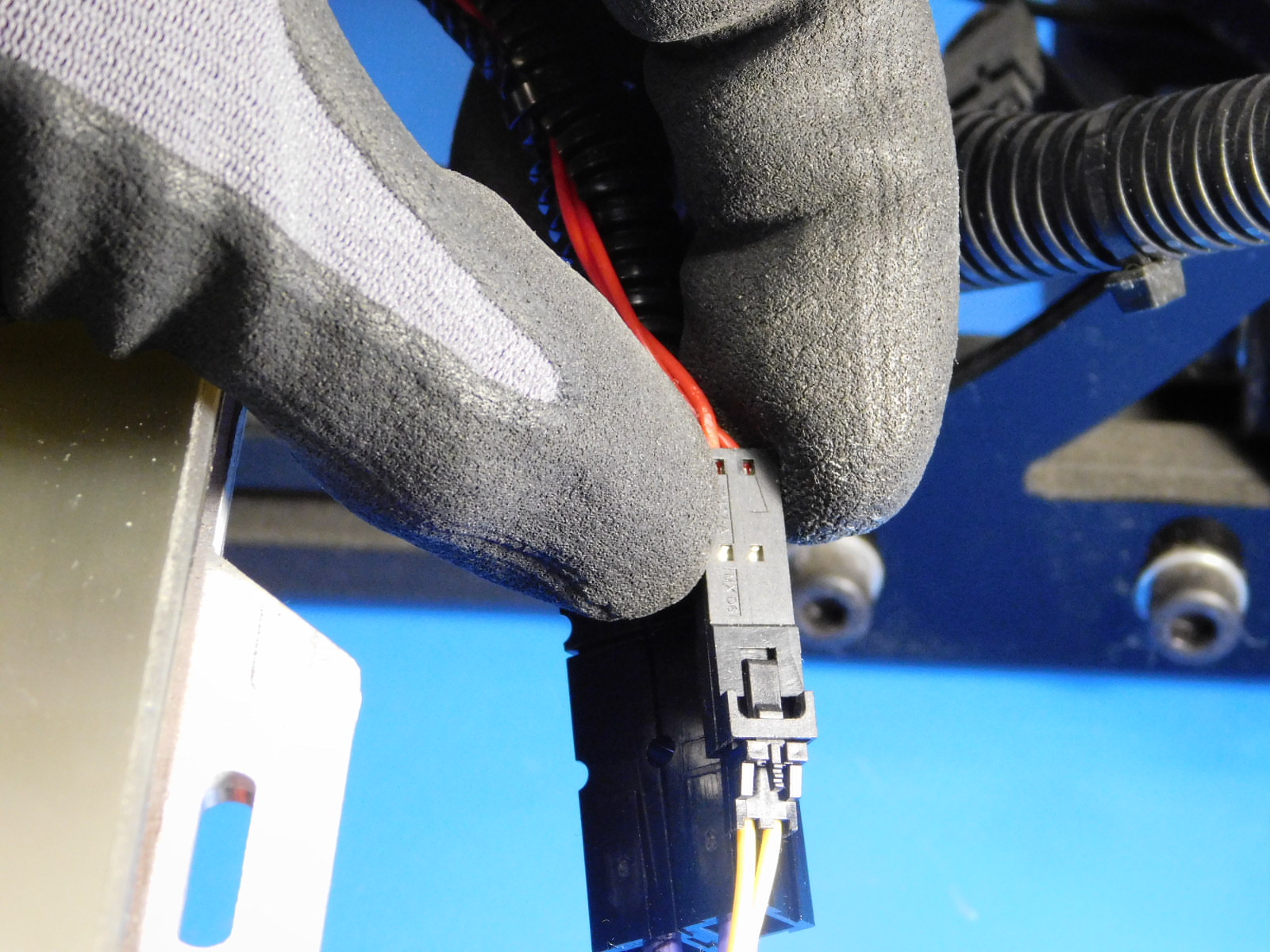
Connect bed power (double purple) to RAMBo at the location shown.
Lay the extra length of the bed power harness along the bottom inner flange of the control box as pictured.
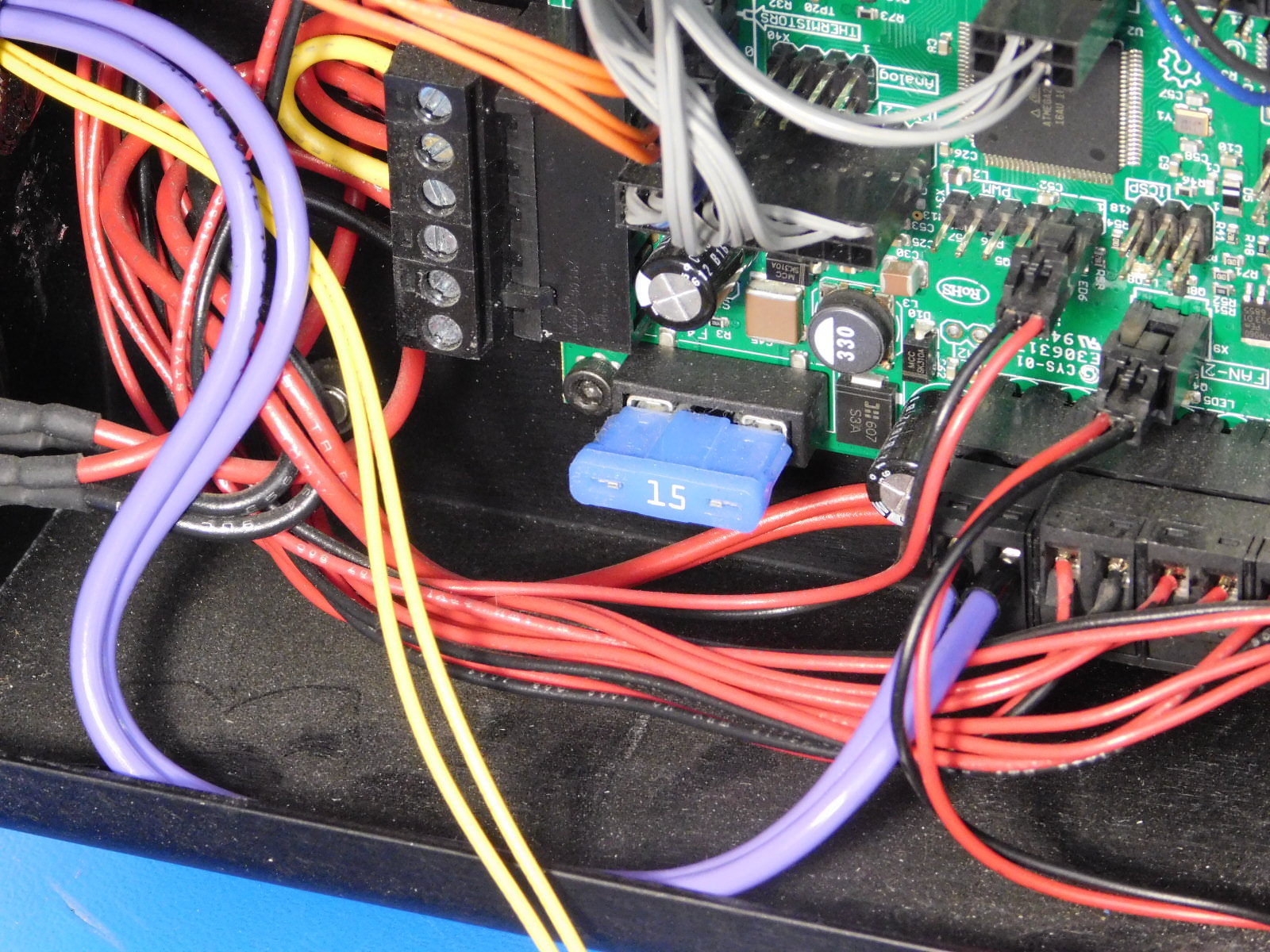
Connect the bed thermistor to the RAMBo at the location shown.
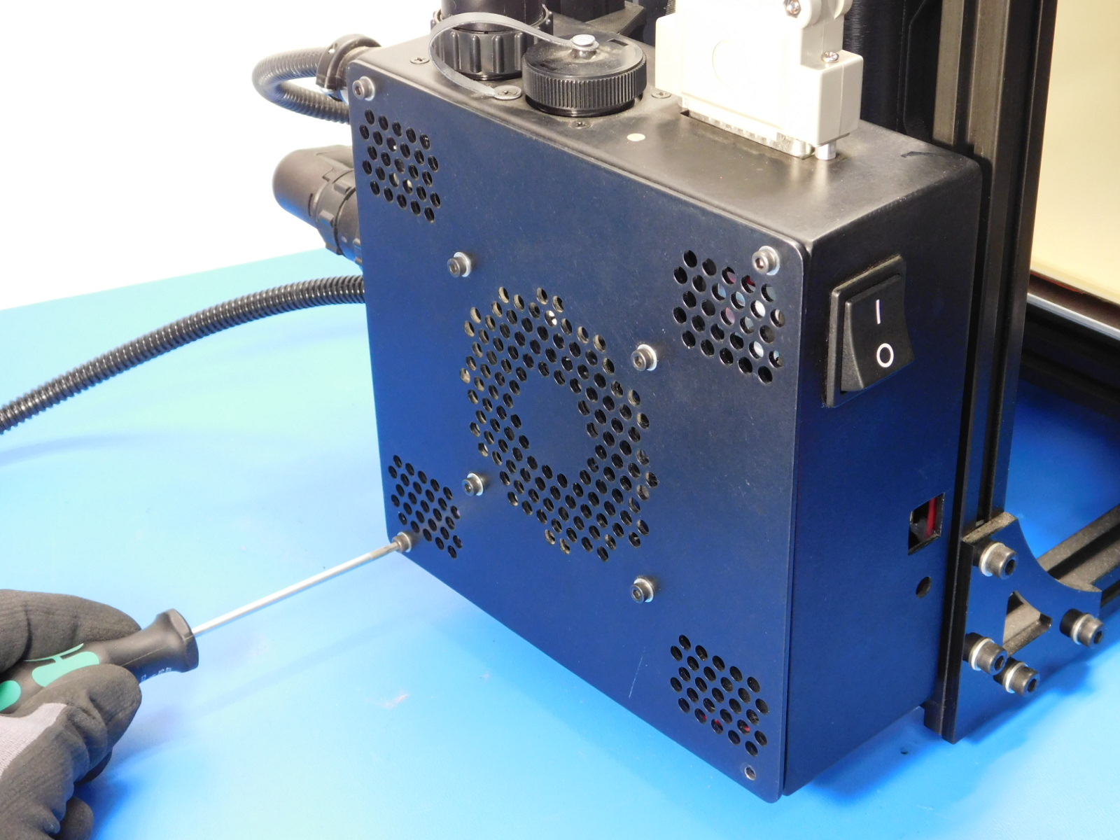
Place the control box cover back over the control box, ensuring that the fan wires do not become pinched in the process.
Secure the control box cover using the four M3x12 fasteners removed in Step 4.

Connect the Anderson PowerPole connectors as shown, ensuring that the connector is pressed together fully.
Connect the bed thermistor connector to the heat bed as shown.
Use one zip-tie to secure the bed harness to the bed plate.


You've now completed replacing your bed harness!