Open HardwareAssembly Instructions
Guides for installation and assembly of the LulzBot line of products made by FAME 3D LLC.
Guides for installation and assembly of the LulzBot line of products made by FAME 3D LLC.
1x- [EL-HR0190] Kangaroopaw, Syringe pump Harness
1x- [EL-MT0063] NEMA 11 Standard Hybrid Stepper Motor
1x- [EL-SW0022] SWITCH BASIC 3A 125V
5x- [HD-BT0005] M3x10 SHCS, Black-Oxide
3x- [HD-BT0116] M3x10 FHCS, Black-Oxide
3x- [HD-BT0130] M3x8 FHCS, Black-Oxide
2x- [HD-BT0137] M3x8 BHCS, Black-Oxide
5x- [HD-BT0157] M3x8 SHCS, Black-Oxide
4x- [HD-BT0244] M2x6 FHCS, Black-Oxide
3x- [HD-BT0255] M2.5x4 SHCS, Black Oxide
2x- [HD-BT0259] M2x8 SHCS, Black-Oxide
1x- [HD-BU0051] iglideR G300 Sleeve Bearing, 12mm Long
2x- [HD-MS0470] Two Side Rubber Seal Bearing
1x- [HD-MS0058] Wire Tie, 8" Black
1x- [HD-NT0359] Helix - Lead Nut, Standard, Inch Flanged 3/16" x 0.20
1x- [HD-RD0076] Leadscrew, 99mm, 3/16", Stainless Steel, 0.2" Lead, RH, 4 Start
1x- [HD-RD0077] Smooth Rod, 90mm
3x- [HD-WA0038] M3 Washer
1x- [PP-GP0451] Syringe Pump Mount
1x- [PP-GP0452] Syringe Pump Cover
1x- [PP-GP0705] Ejector Cam
1x- [PP-GP0706] Ejector Lever
1x- [PP-GP0707] Syringe Mounting Shelf
1x- [PP-GP0708] Syringe Mounting Base
1x- [PP-MP0252] Steel Worm Gear, 5mm Bore
1x- [PP-MP0253] Bronze Worm Wheel, 4mm Bore
1x- [PP-MP0277] Kangaroo Paw, Tool head, Upper Bearing Holder
1x- [PP-MP0278] Kangaroo paw, Tool head, Lower Bearing Holder
1x- [PP-MP0279] Kangaroo Paw, Tool head, Motor Mount
1x- [PP-MP0280] Kangaroo Paw, Tool head, Collar Mount Flange
1x- [PP-MP0281] Kangaroo Paw, Tool head, Carriage
a.)
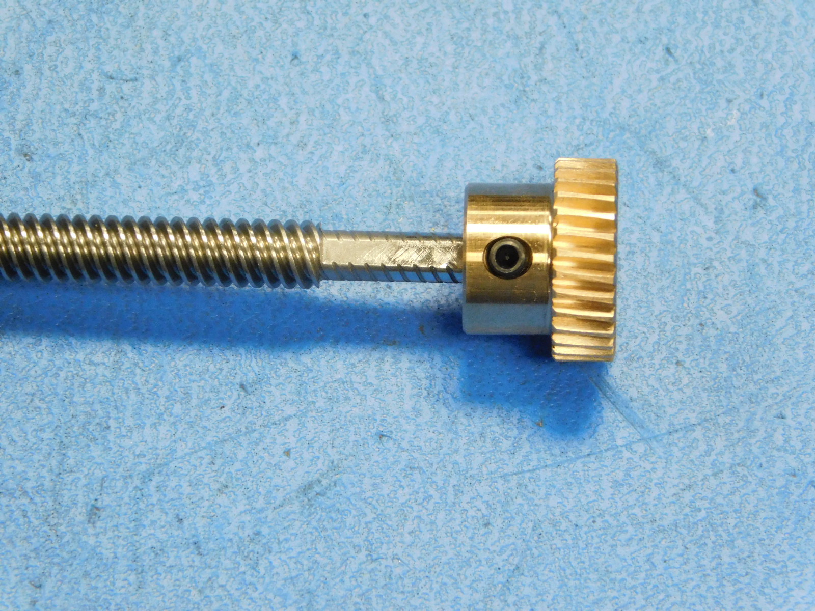
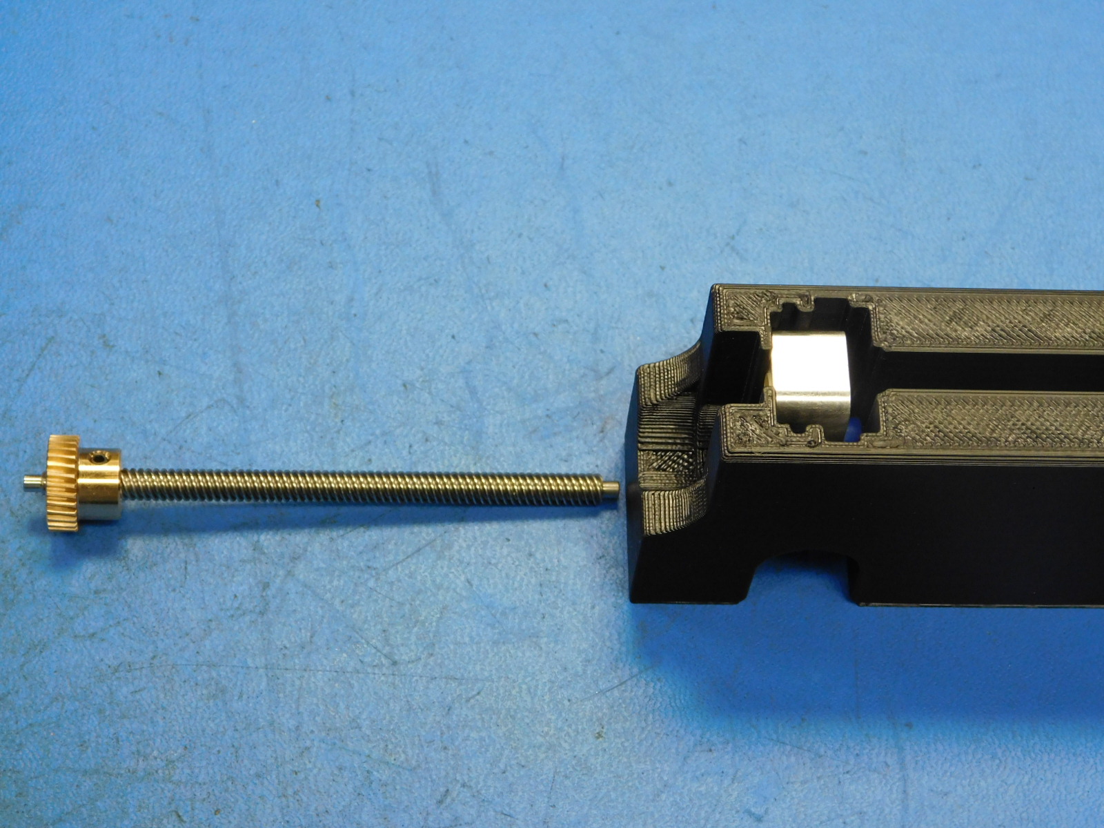
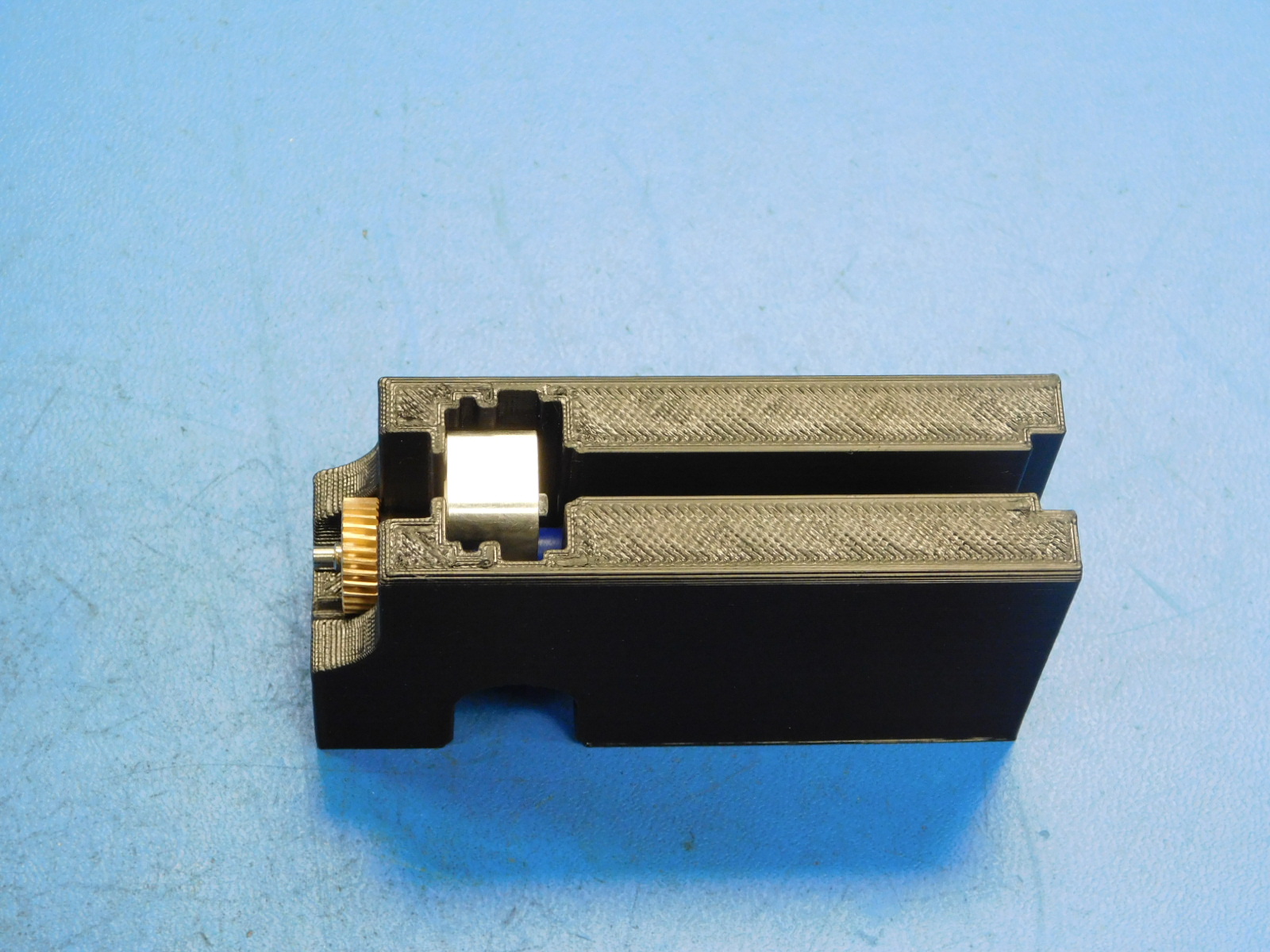
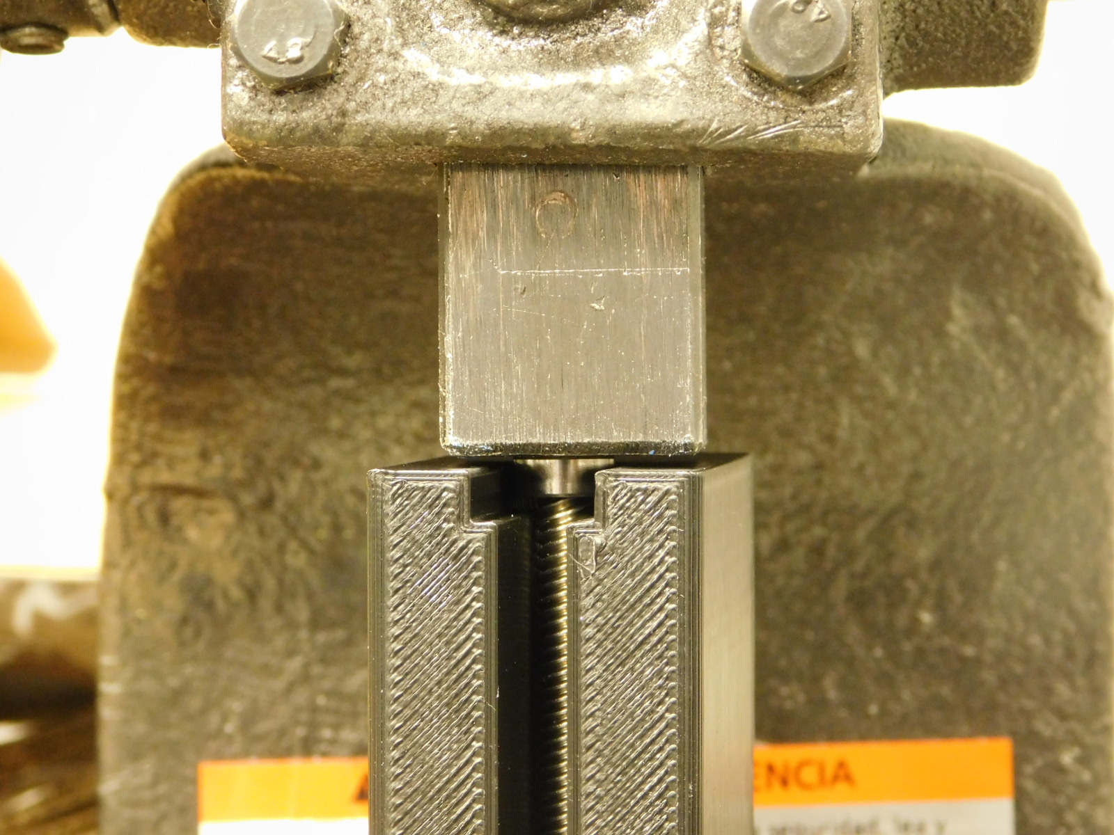
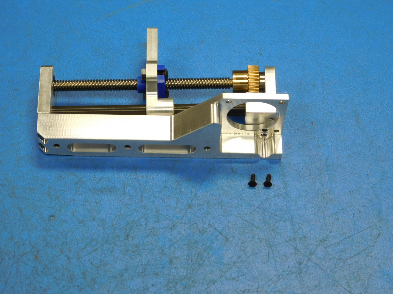
Slide the Bronze Worm Wheel [PP-MP0253] to the unthreaded portion of the Leadscrew [HD-RD0076] with the geared side towards the end of the Leadscrew.
Ensure the Worm Wheel is on the Leadscrew as fas as it will go; the top of the Worm Wheel should mate against the start of the Leadscrew threads. See photo
b.)
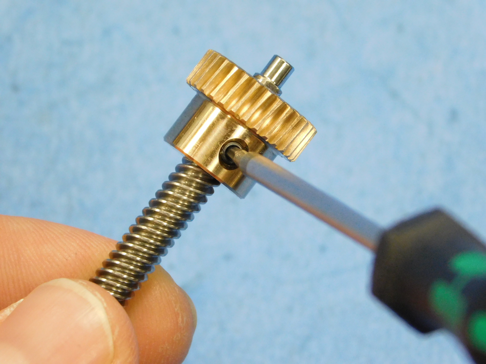
Torque the set screw of the Worm Wheel to the flat side of the Leadscrew to 2 in*lbs.
a)
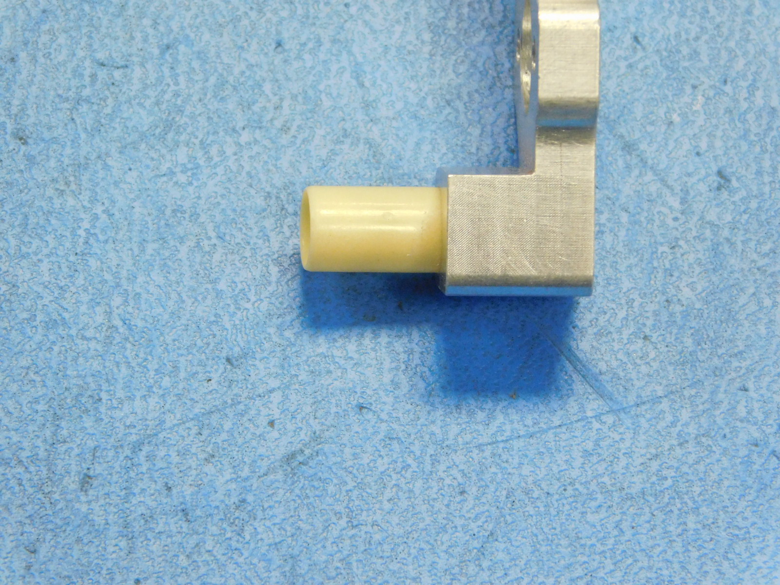
Start one Sleeve Bearing [HD-BU0051] in the hole of the Carriage [PP-MP0281] in the orientation shown.
b)
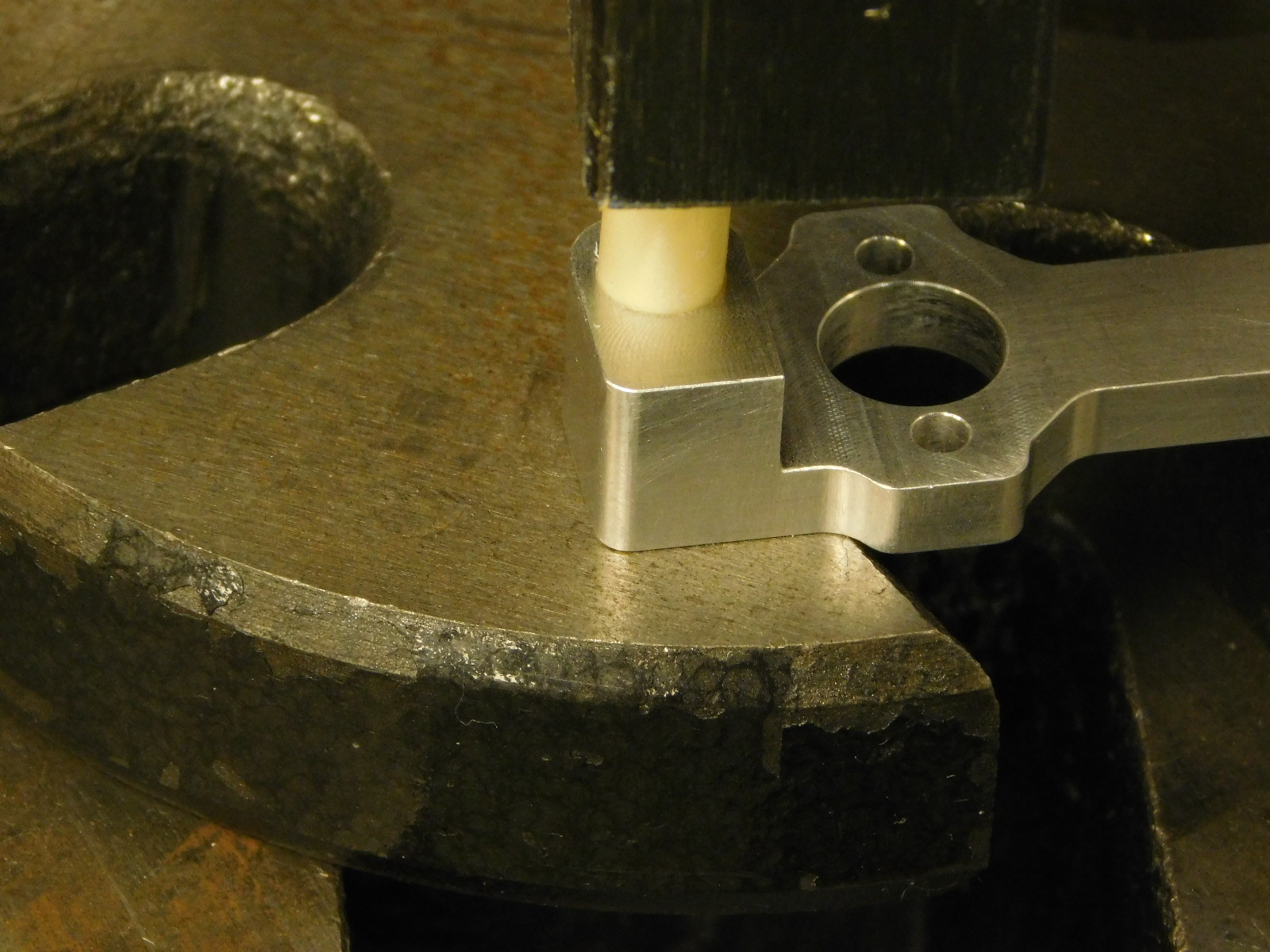
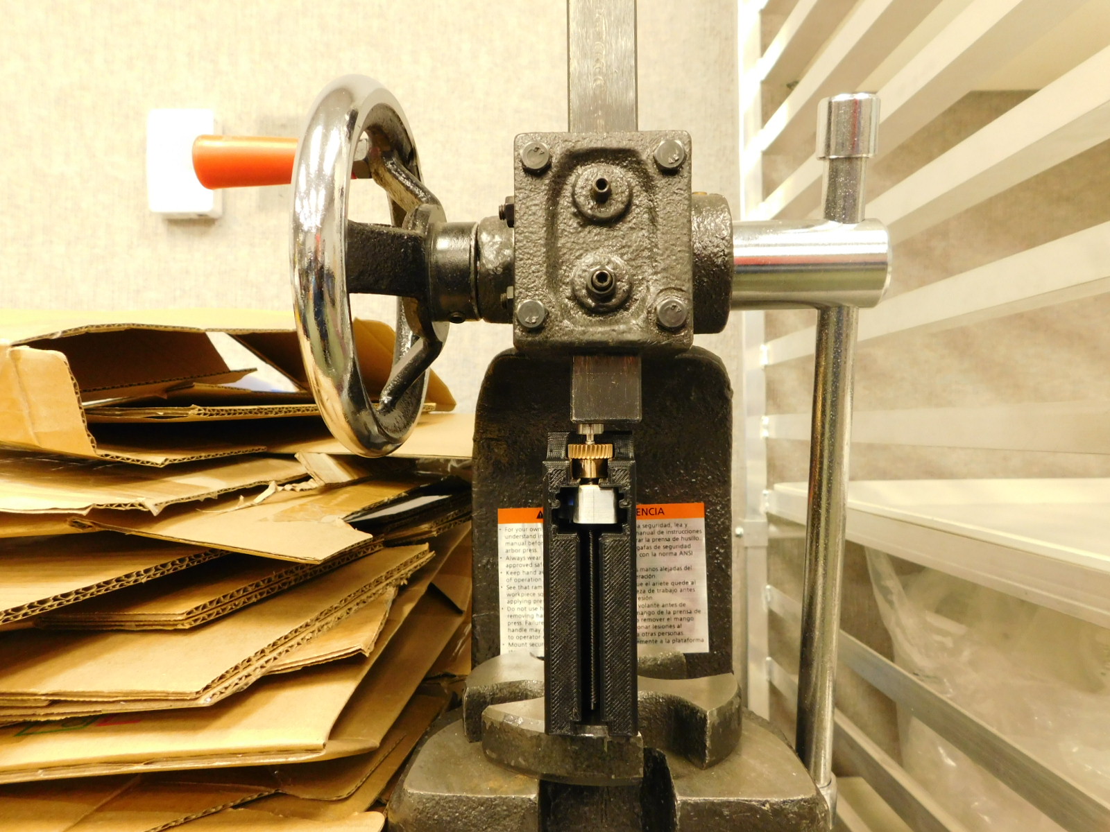
Place the Carriage [PP-MP0281] flat side down on a flat portion of the arbor press working area.
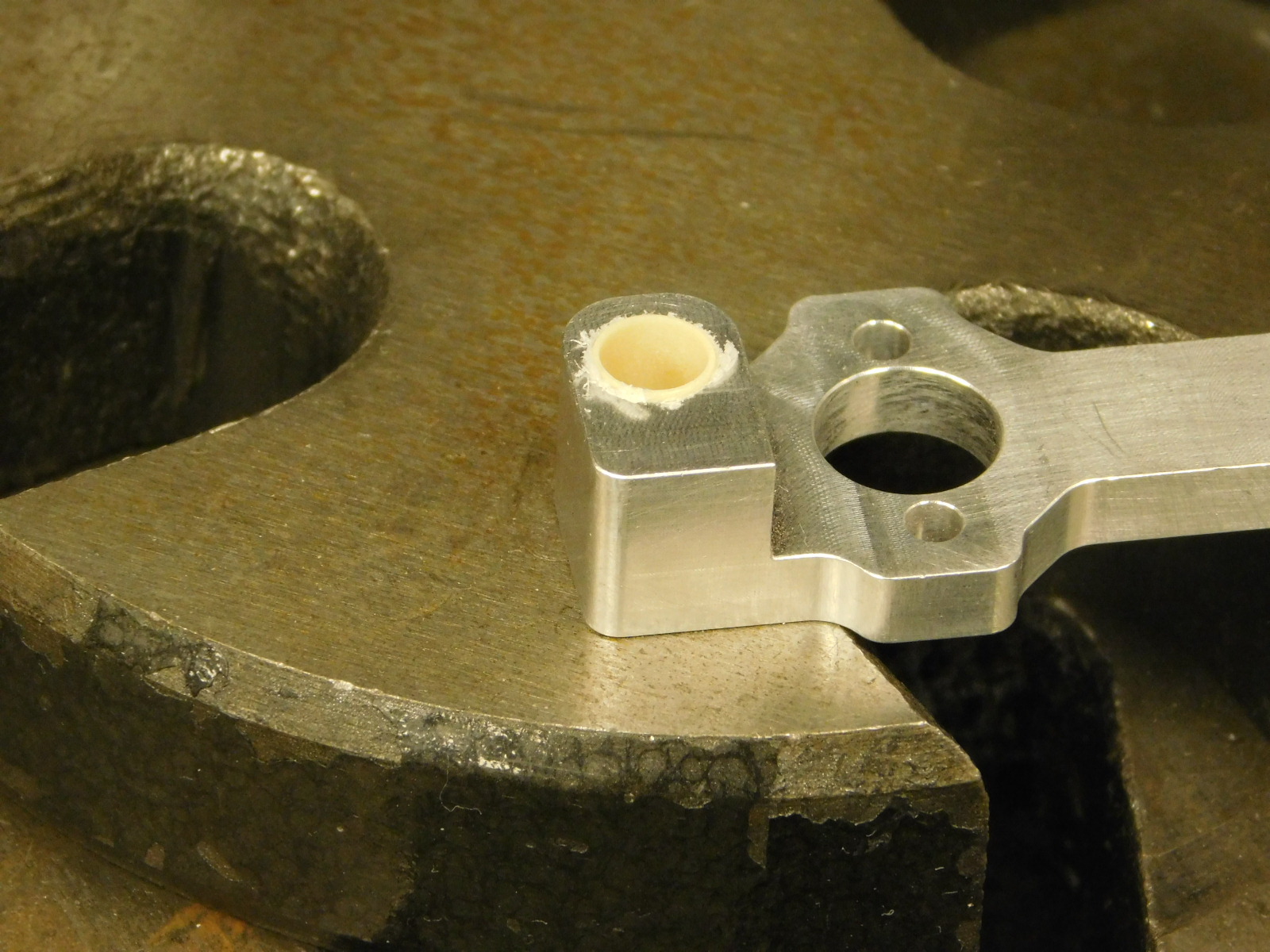
c)
Use the arbor press to slowly push the Sleeve Bearing into the Carriage until it bottoms on the arbor press plate. Do not compress the sleeve bearing further as it will mushroom the end and could cause additional drag.
d)
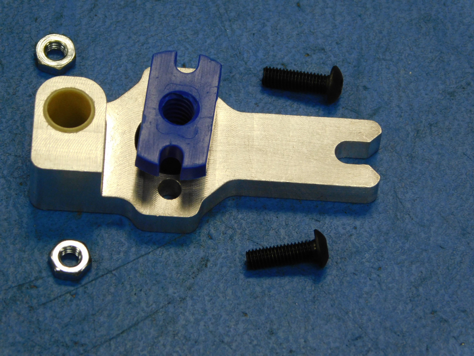
Using two M3x8 BHCS [HD-BT0137], secure the Helix - Lead Nut [HD-NT0359] to the Carriage as shown.
Early builds use M3x10 BHCS HD-BT0148 with M3 Nuts HD-NT0004, production parts should have these holes threaded

a)
Place the assembled carriage into the assembly jig as shown (only fits in one orientation).
b)
Thread the end of the Leadscrew opposite the Worm Wheel into the Lead Nut of the Carriage until the Worm Wheel bottoms out in the jig.

a)
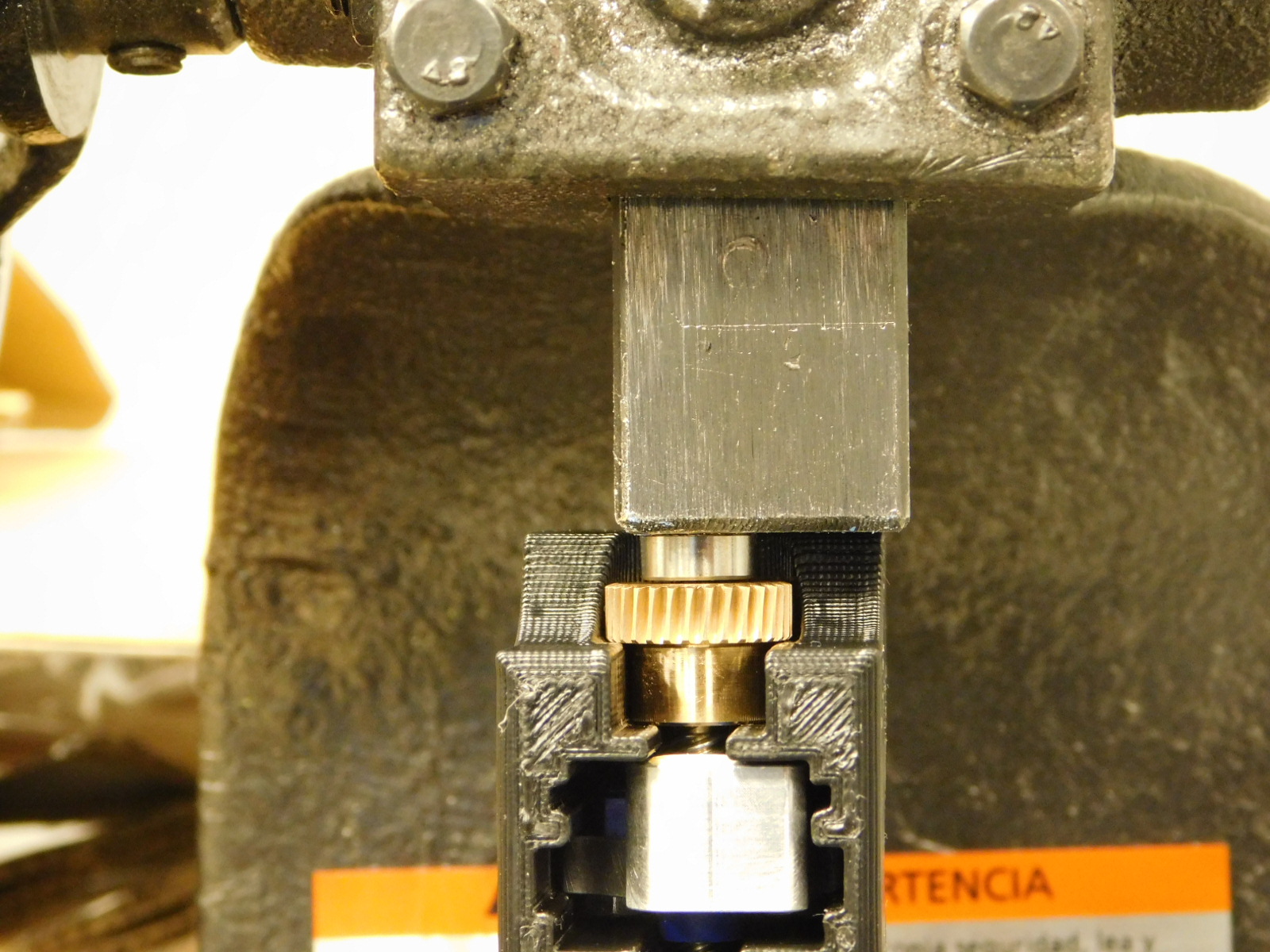
At the arbor press, place the part/jig from the previous step into the working area of the arbor press with the bronze Worm Wheel facing up.
Ensure the Worm Wheel end is tightened into the jig by spinning it, before pressing bearings into place.
b)
Place one bearing [HD-MS0470] on the end of the Leadscrew and use the arbor press to press it into place.
Visually inspect to ensure the bearing is fully seated on the end of the Leadscrew.
c)
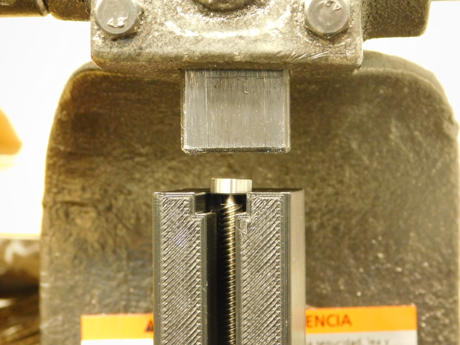
Rotate the jig in the arbor press working area so that the opposite end of the Leadscrew faces up.
d)
Place one bearing [HD-MS0470] on the end of the Leadscrew and use the arbor press to press it into place.
Visually inspect to ensure the bearing is fully seated on the end of the Leadscrew.
e)
Use the finger notch on the rear/bottom of the jig to eject the completed Leadscrew assembly.

a)
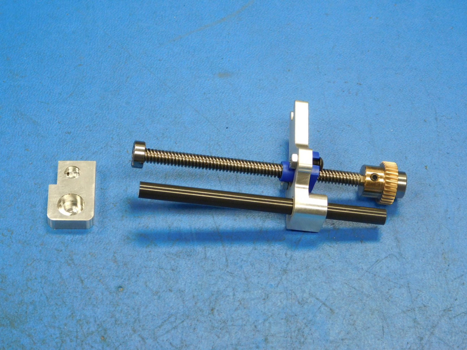
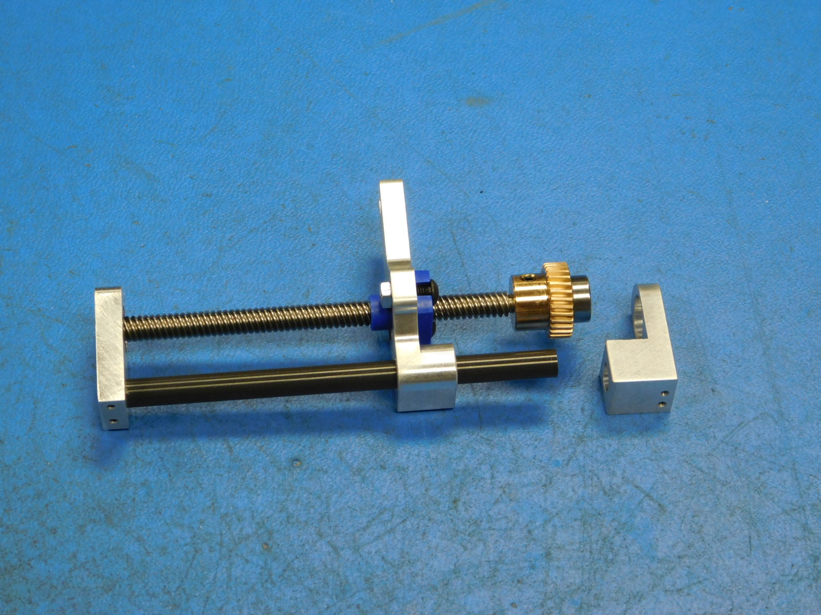
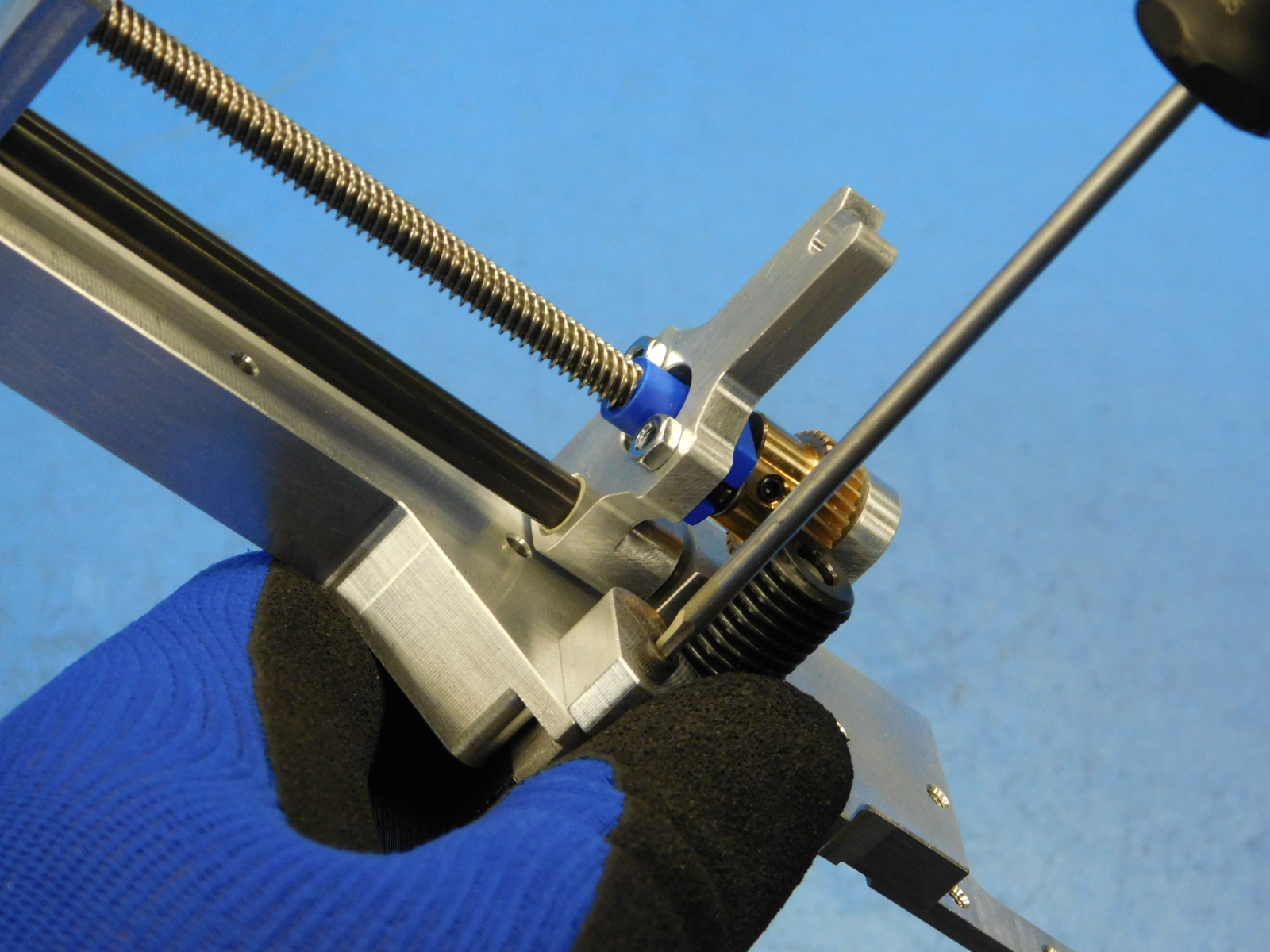
Obtain one Upper Bearing Holder [PP-MP0277] and press it onto the bearing at the opposite end of the bronze Worm Wheel.
b)
Slide one Smooth Rod [HD-RD0077] through the sleeve bearing of the Carriage and into the hole in the Upper Bearing Holder.
c)
Obtain one Lower Bearing Holder [PP-MP0278] and press it onto the bearing at the Leadscrew end with the bronze Worm Wheel. Ensure the end of the smooth rod enters the hole in the lower bearing holder.
a)
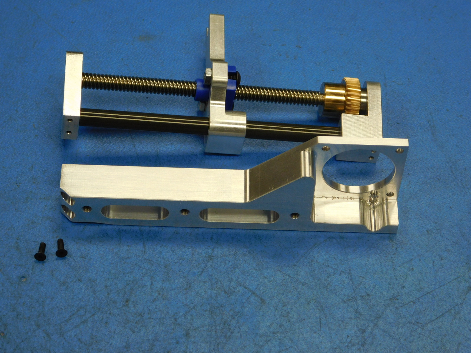
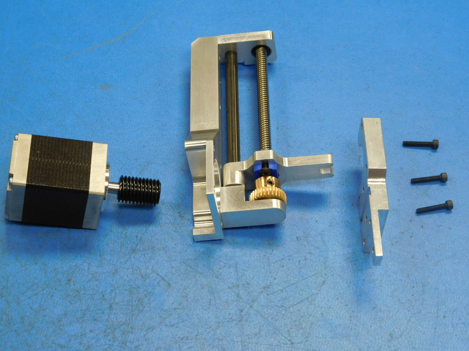
Obtain one Motor Mount [PP-MP0279]
b)
Using two M2x6 FHCS [HD-BT0244], attach the Upper Bearing Holder to the Motor Mount.
Before tightening, ensure the edges of the Upper Bearing Holder and Motor Mount mate flush and square.
c)
Using two more M2x6 FHCS [HD-BT0244], attach the Lower Bearing Holder to the Motor Mount.
d)
Torque all four fasteners to 2in\lbs
a) Obtain one Steel Worm Gear [PP-MP0252] and one NEMA 11 Motor [EL-MT0063]
b)
Using the pulley spacer jig, attach the Steel Worm Gear to the shaft of the NEMA 11 Motor with the set screw towards the motor.
c)
Torque the set screw against the flat side of the motor shaft to 2in*lbs
d)
Place the Motor (w/ Worm Gear) on top of a paper towel.
Give a quick shot of White Lithium spray to one side of the Worm Gear and then rotate and apply another quick shot to the other side of the Worm Gear.
a)
Obtain one Collar Mount Flange [PP-MP0280] and 3 M2.5x14 SHCS [HD-BT0255]
b)
Orient the parts as shown
The motor's connector is facing down in the photo
c)
Thread the M2x5x14 SHCS through the Collar Mount Flange and the Motor Mount, and into the threaded holes on the motor.
d)
Apply pressure to the motor so that the Steel Worm Gear is pressed as close to the bronze Worm Wheel as possible and tighten the fasteners.
e)
Torque all 3 fasteners to 3in*lbs
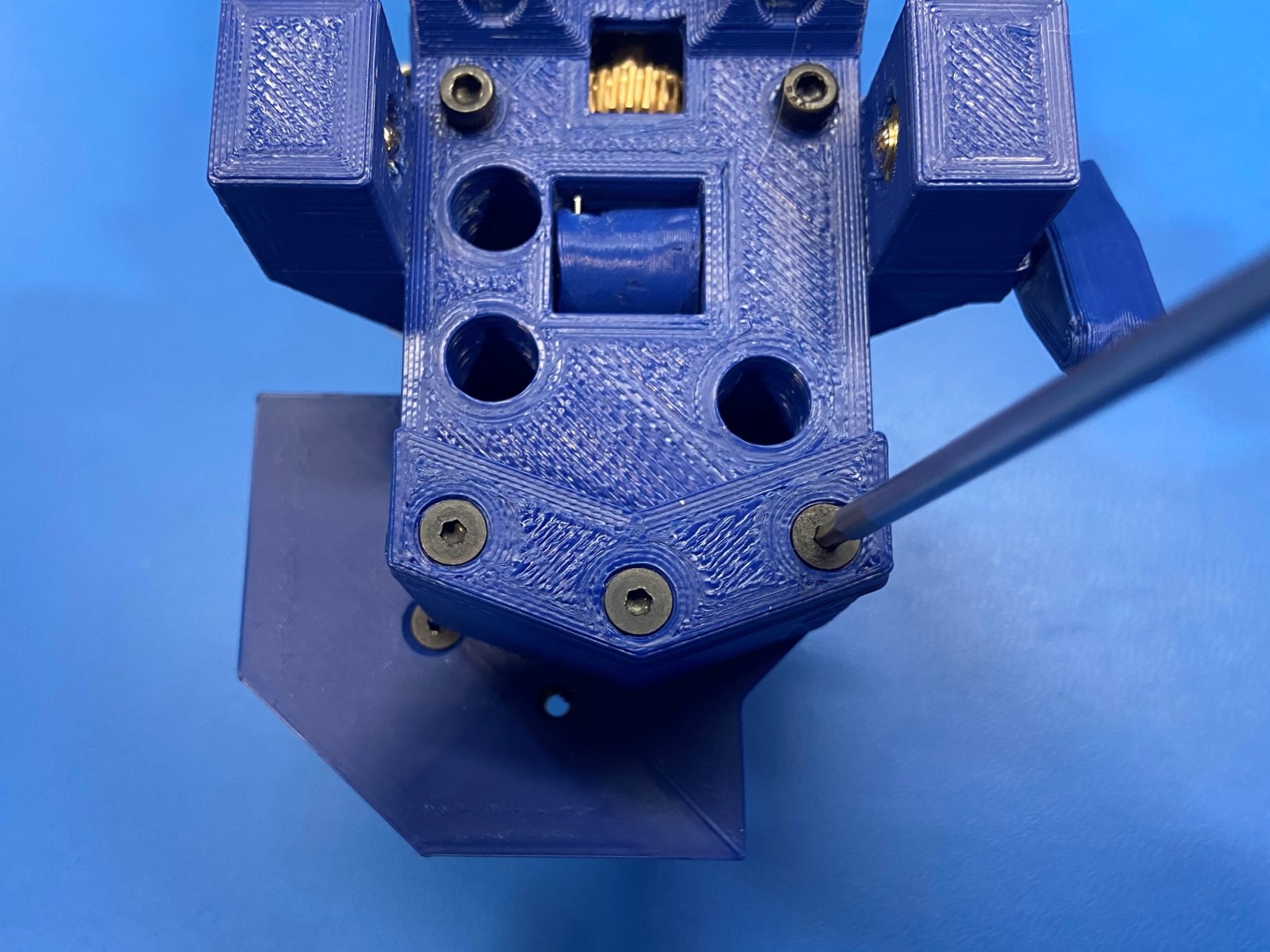
Place the syringe pump mount [PP-GP0451] on the bottom of the collar mount flange and use 3x M3x8 FHCS [HD-BT0130].
Once syringe pump mount is attached torque the bolts to 5in*lbs

Use 3x M3x10 SHCS [HD-BT0005] to mount the syringe mounting base [PP-GP0708] to the collar mount flange. Secure using the 3 M3x10 SHCS, torqued to 5in*lbs
Then fasten 2x M3x10 SHCS [HD-BT0005] into the two guide holes on the front of the syringe mounting base.
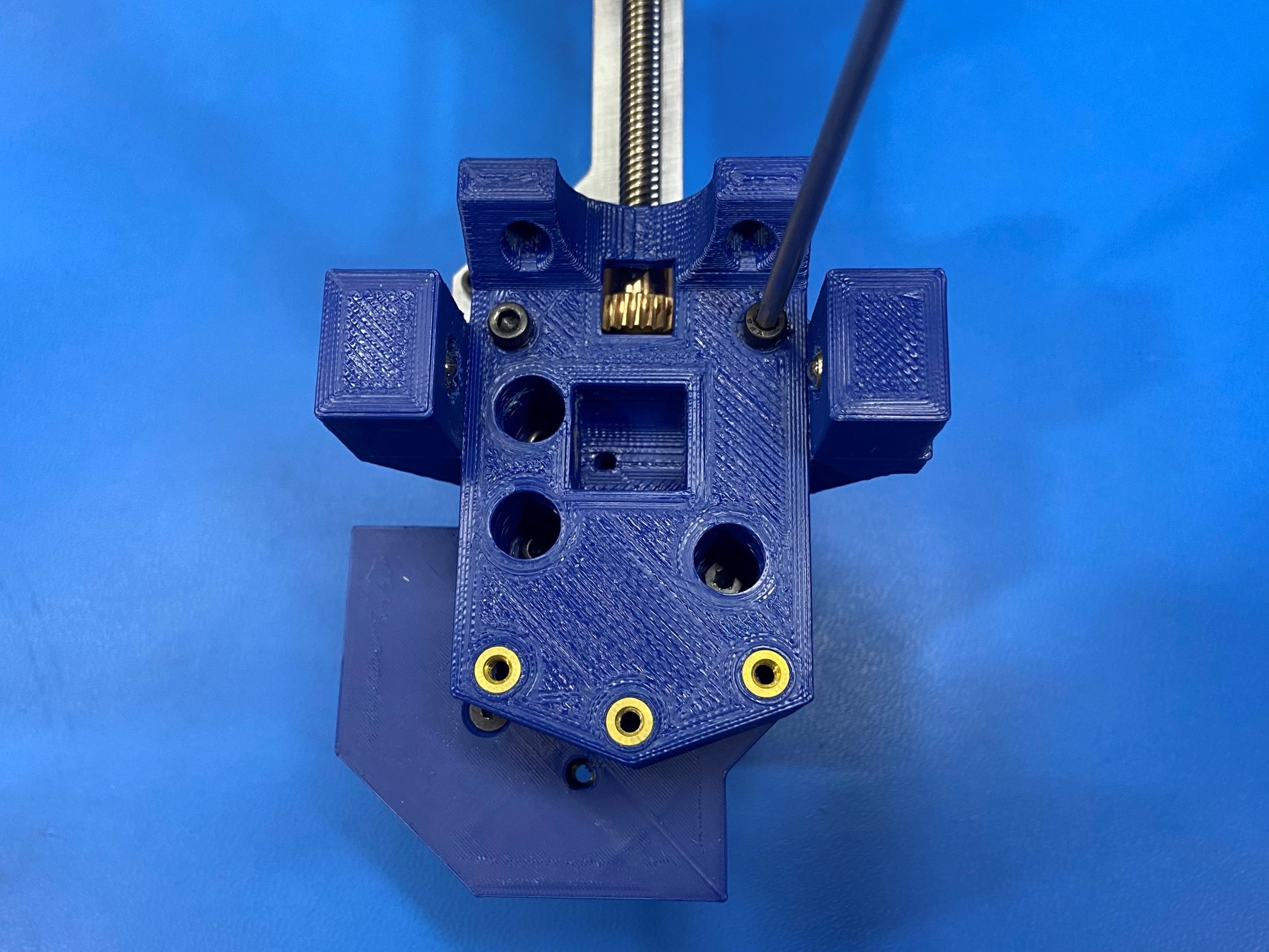
Using 1x endstop switch [EL-SW0022] and 2x M2x8 SHCS[HD-BT0259] mount the endstop switch to the assembly with the tabs facing away from the motor and the switch next to the threaded rod
Torque to 2in*lbs
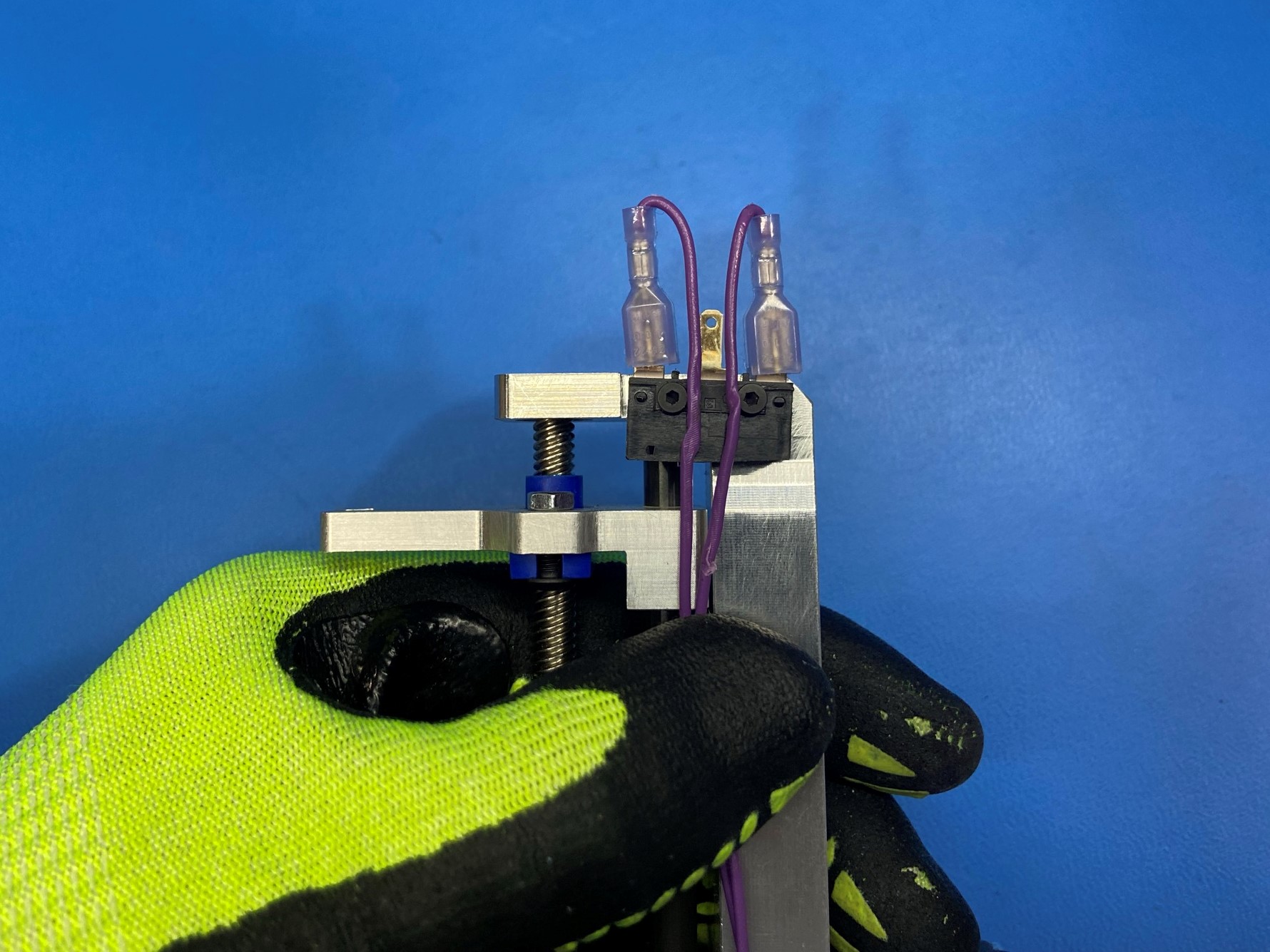
Attach the syringe pump harness [EL-HR0190] to the endstop switch outer tabs.
Bend the endstop switch tabs in towards the motor mount to about 70 degrees.
Then route the wires in-between the two connector.


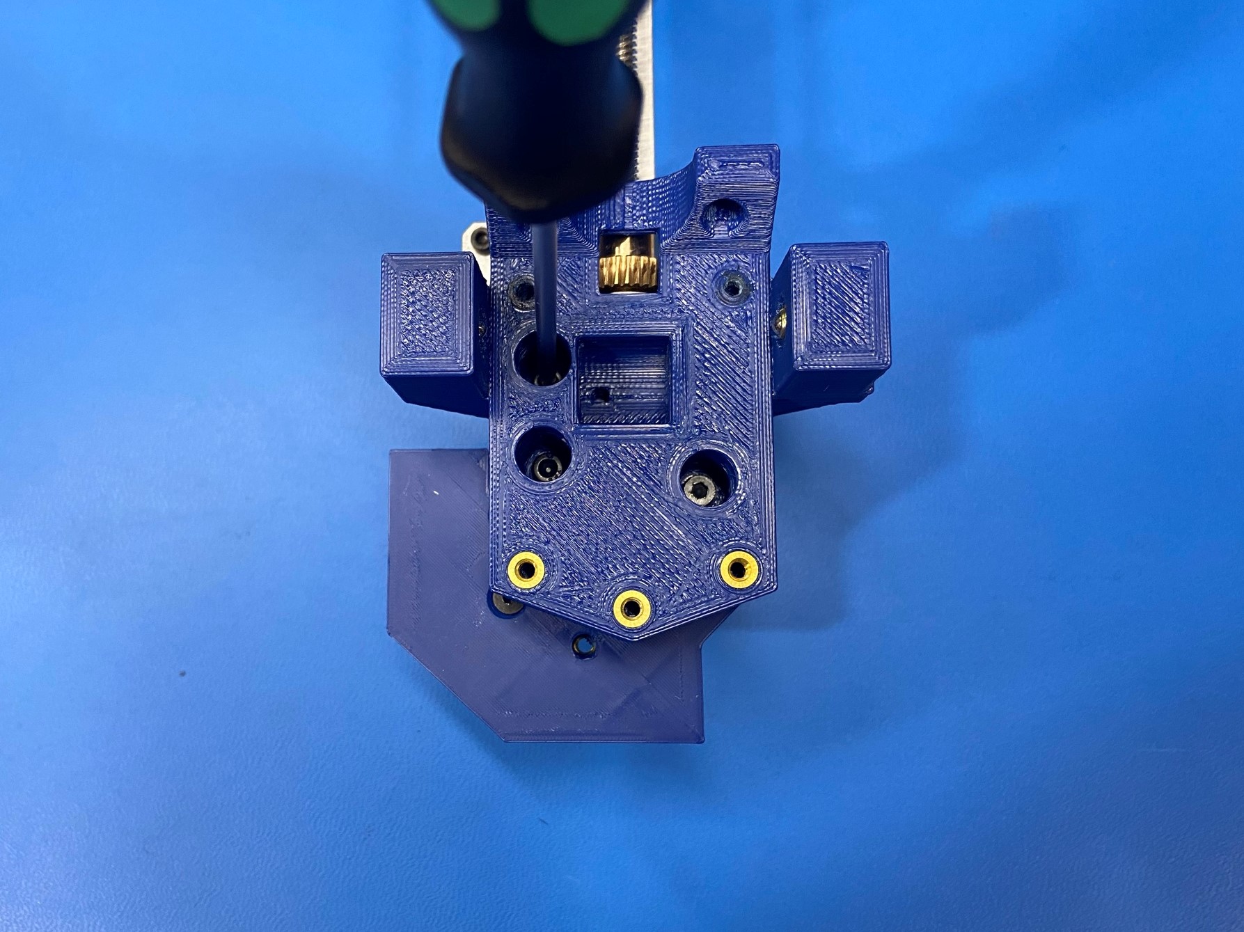
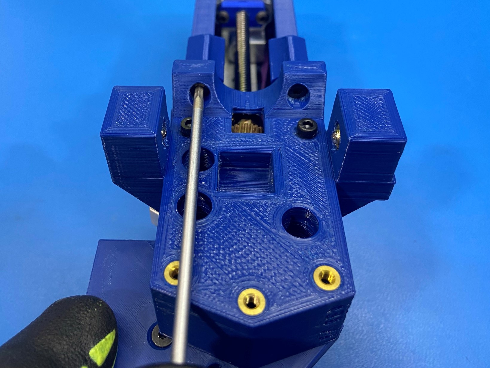
Use 1x syringe pump cover [PP-GP0452], 5x M3x8 SHCS [HD-BT0157], and 3x M3 washers [HD-WA0038] attach the syringe pump cover to the assembly
Make sure the endstop switch wires (purple wires) lead down between the two outer tabs of the switch and down the side of the motor mount
Then slide the syringe pump cover onto the assembly making sure the side that has the three holes is on the backside of the assembly
Secure the cover using 2x M3x8 SHCS to attach the syringe pump cover to the syringe mount base
Secure from the rear using 3x M3x8 SHCS with washers
Torque all 5 fasteners to 3in*lbs
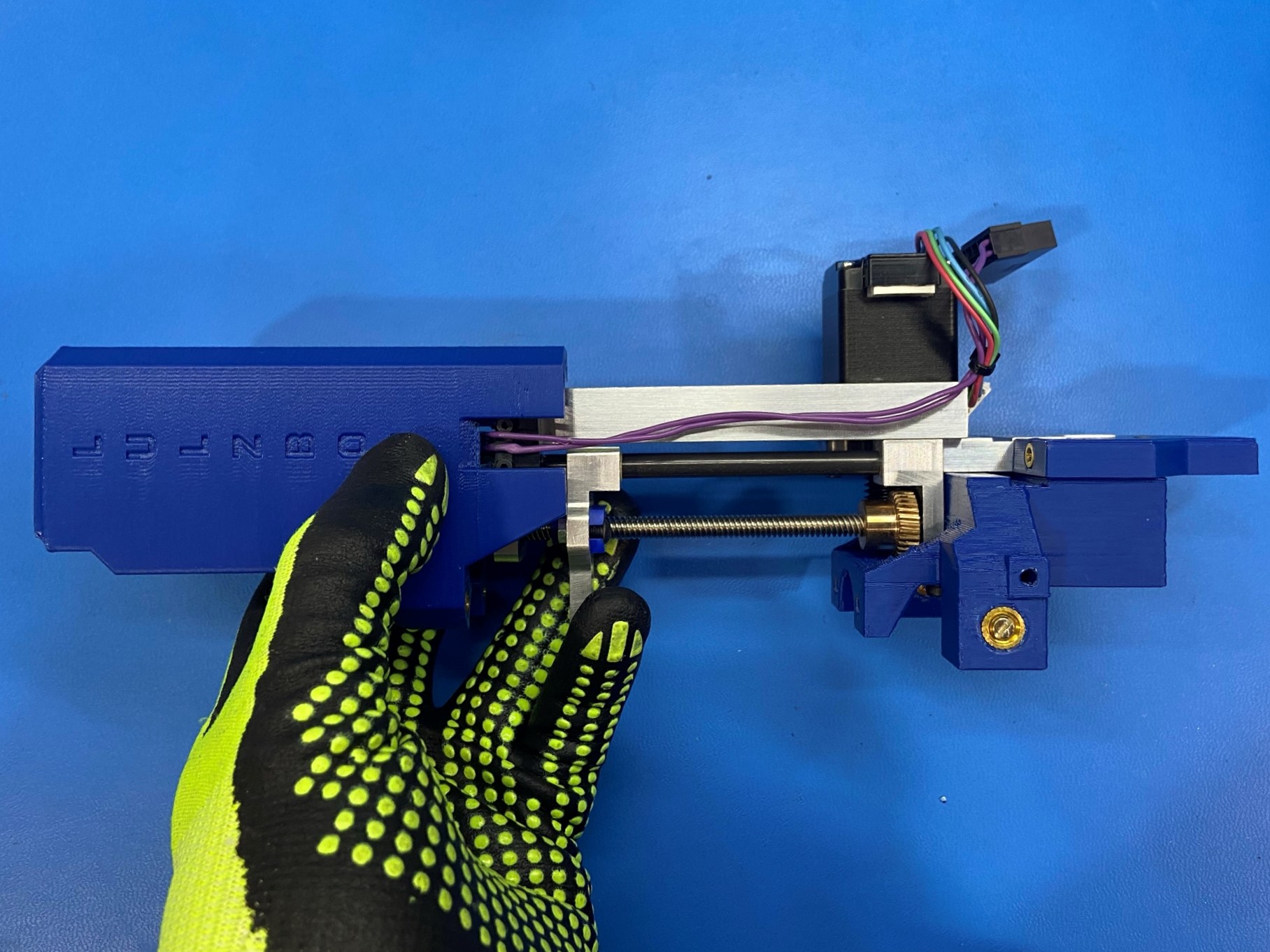

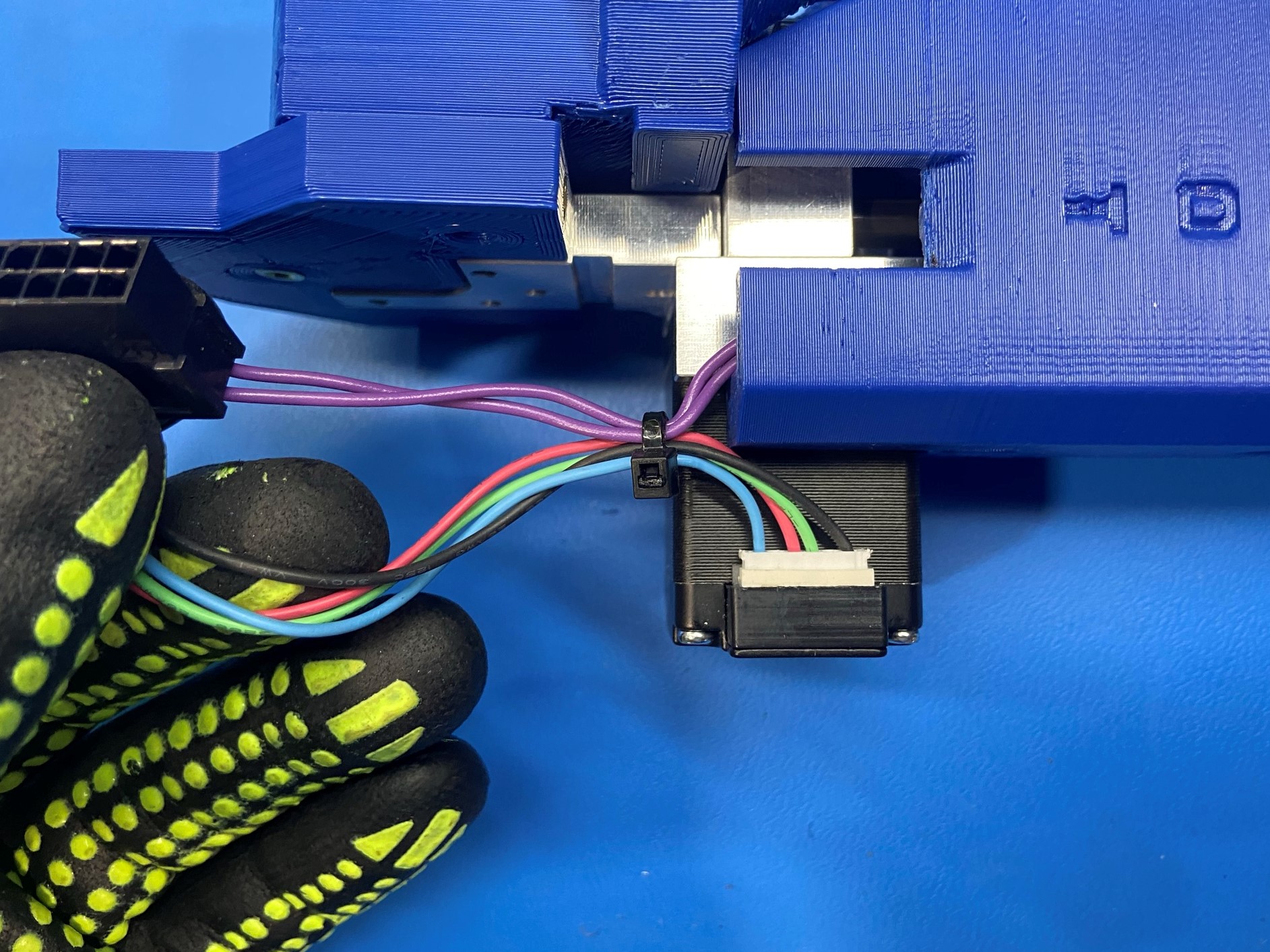
Connect the small white connector of the syringe pump harness to the NEMA 11 motor.
Then pulling the slack from the purple wires, apply one zip-tie [HD-MS0058] around the motor leads and the endstop leads, as close to the corner of the Syringe Pump Cover, as shown.
Trim excess zip-tie so that it's flush with the latch.
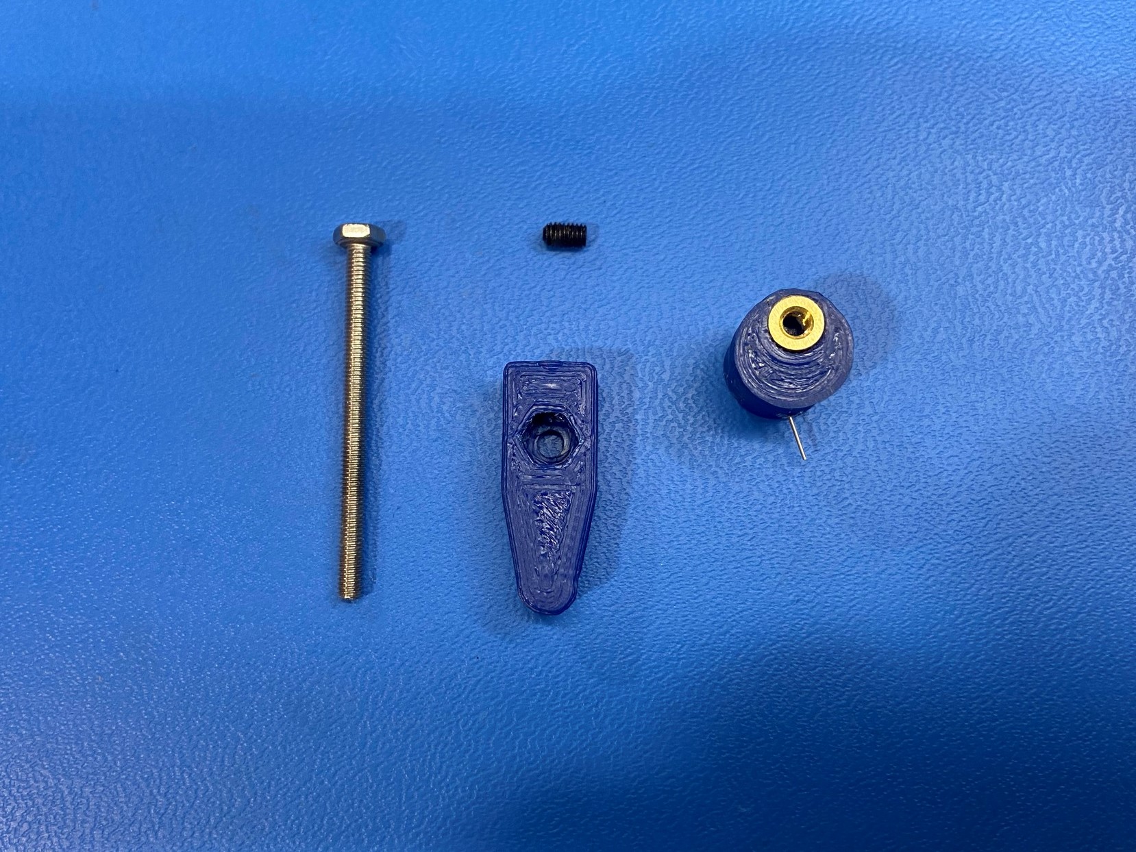
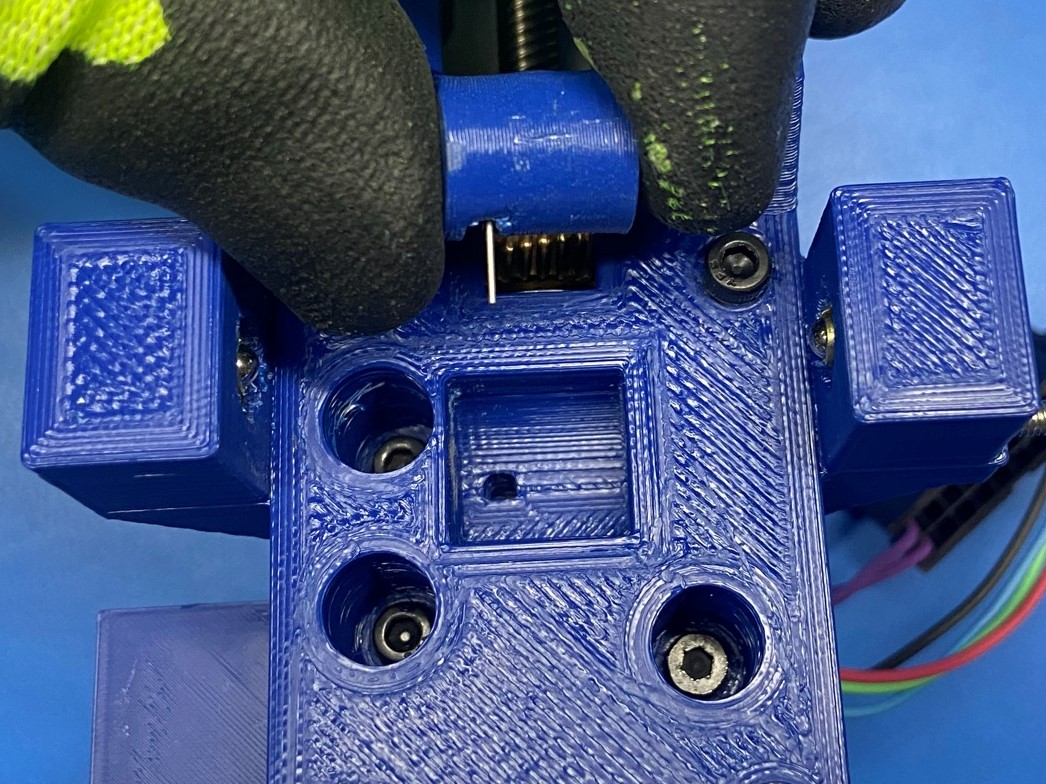
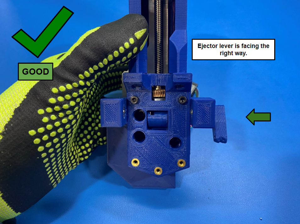
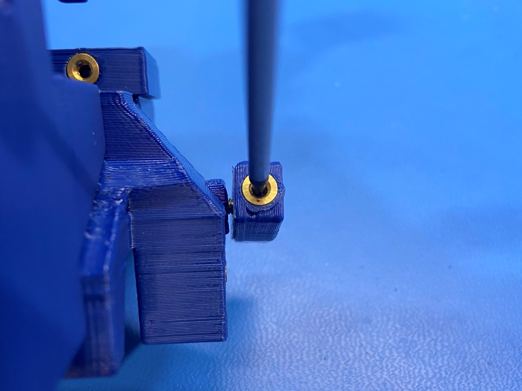
Place the ejector cam [PP-GP0705] inside the cavity on the syringe mounting base. Make sure to align the spring with the square hole inside the cavity.
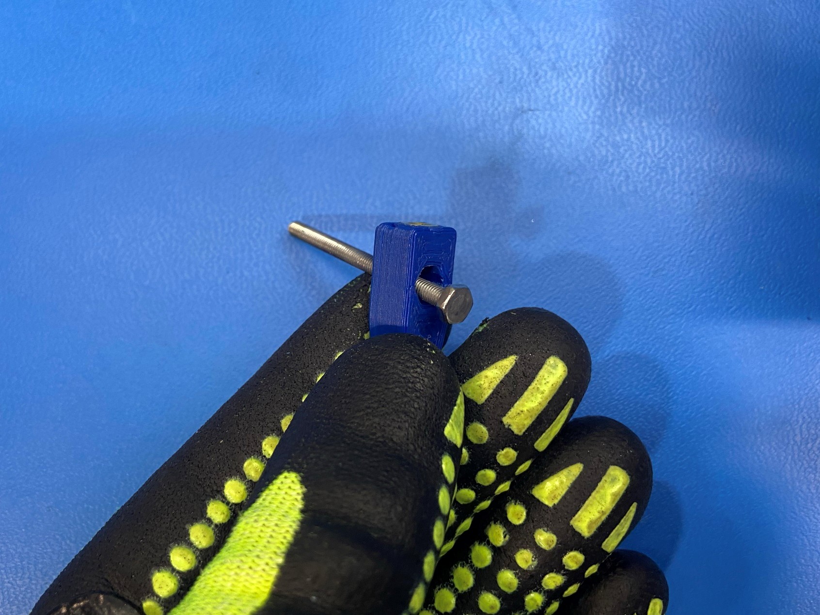
Then slide the M3x20 HHCS [HD-BT0###] through the ejector lever [PP-GP0706] making sure the head of the bolt is on the same side as the hex hole on the ejector lever, but wait to slide the ejector lever onto the head of the bolt
Now align the insert on the ejector cam with the bolt and fasten, once the bolt tightens up align the ejector cam with the head of the bolt.
Keep tightening the bolt until the cam rotates with the lever, once this happens make sure the lever is facing toward the front of the assembly while pointing down.
If the lever is not in this position loosen bolt and realign the lever with the head of the bolt.
Once the lever is in the correct orientation use the M2x6 set screw [HD-BT0###] and secure the lever to the head of the bolt.

Using 3x M3x10 FHCS [HD-BT0116] attach the syringe mounting shelf [PP-GP0707] to the syringe mounting base.