Open HardwareAssembly Instructions
Guides for installation and assembly of the LulzBot line of products made by FAME 3D LLC.
Guides for installation and assembly of the LulzBot line of products made by FAME 3D LLC.
1x- [DC-LB0155] Caution Hot Symbol
1x- [AS-CB0061] Extruder Motor Harness
1x- [AS-CB0066] Thermistor Harness
1x- [AS-CB0064] v2Aero Heatsink Fan Harness
1x- [AS-CB0112] Titan SK Extruder Blower Harness
1x- [EL-MT0069] NEMA 17 Half Height Stepper Motor
1x- [EL-WR0158] Self-Wrapping Braided Sleeving- 3/8 100mm
4x- [HD-BT0039] M3x12 SHCS, Black-Oxide
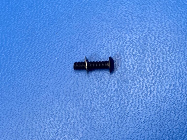
1x- [HD-BT0042] M3x30 SHCS, Black-Oxide
3x- [HD-BT0043] M3x35 SHCS, Black-Oxide
1x- [HD-BT0146] M3x12 BHCS, Black-Oxide
1x- [HD-BT0197] M4 Thumb Screw for Aero
1x- [HD-BT0273] M3x45 BHCS, Black-Oxide
2x- [HD-MS0058] Cable Tie 8"
1x- [HD-MS0430] Idler Spring for Aero
2x- [HD-MS0446] Radial Ball Bearing Double Sealed 5mm
1x- [HD-NT0011] M4 Nut
1x- [HD-TB0080] Feed Tube 20mm
1x- [HD-WA0027] M3 Internal Tooth Lock Washer
1x- [HD-WA0038] M3 Washer
1x- [PP-FP0135] E3D Mirrored Aero Idler Lever
1x- [PP-FP0137] E3D Aero Acetal Gear w/ Filament Drive Shaft
1x- [PP-FP0219] E3D Mirrored Aero 1.75mm Filament Guide
1x- [PP-GP0608] Tool Head Connector Boot
1x- [PP-GP0642] 1.75 SK Blower Shroud
1x- [PP-GP0643] 1.75 Extruder Mount
1x- [PP-MP0204] Aero Mirrored Body w/ Threaded Insert, Left
1x- [PP-MP0282] E3D, V3 Aero Steel Pinion Gear w/ Set Screw
Heatsink Assembly

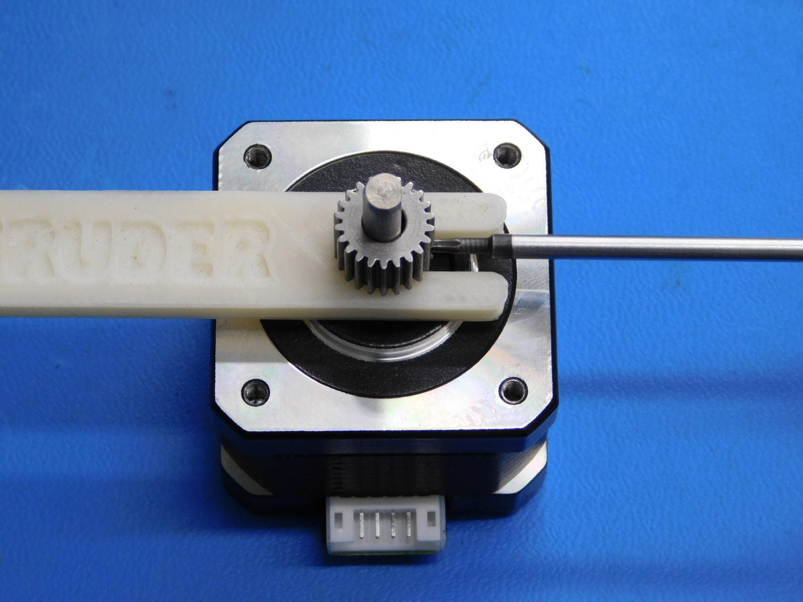
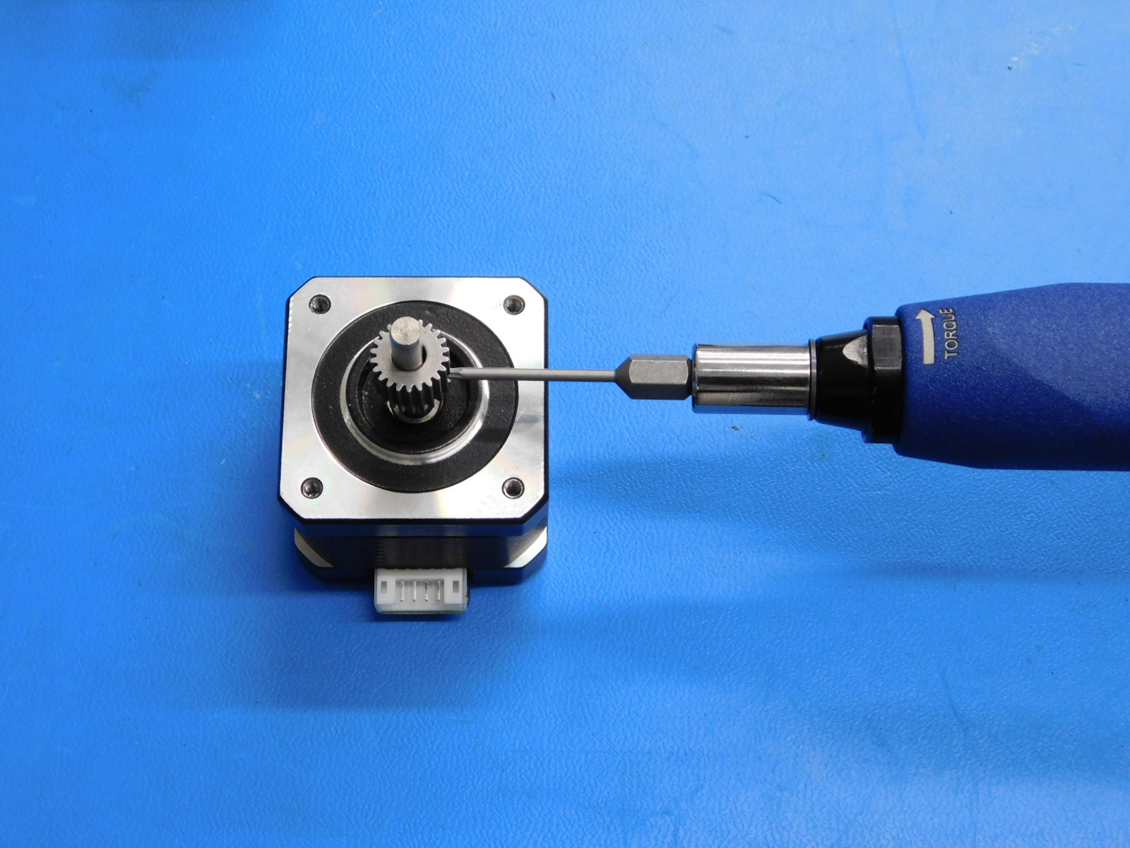
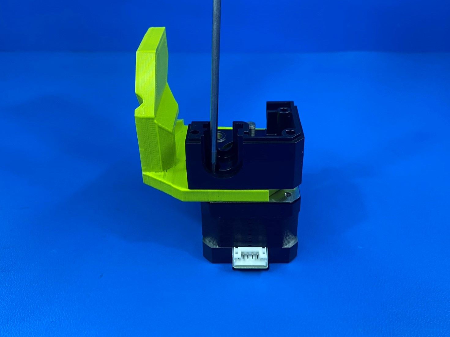
Install the drive gear [PP-MP0282] onto the NEMA stepper motor [EL-MT0069] using the printed drive gear spacer jig as shown. Torque the set screw to 3 in*lbs.
A set screw should come pre-installed in the gear, if not, ensure an M3x3 set screw is used. Set screws of any greater length will interfere with the larger gear during operation.
Thickness of the printed spacer is 5mm
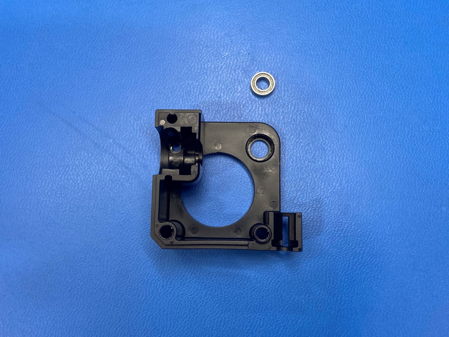
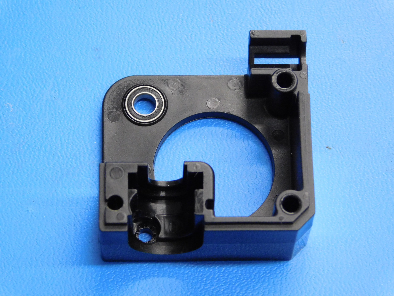
Install 1x radial ball bearing [HD-MS0446] inside the hole on the aero mirrored body [PP-MP0204] make sure the bearing is fully seated inside the hole.
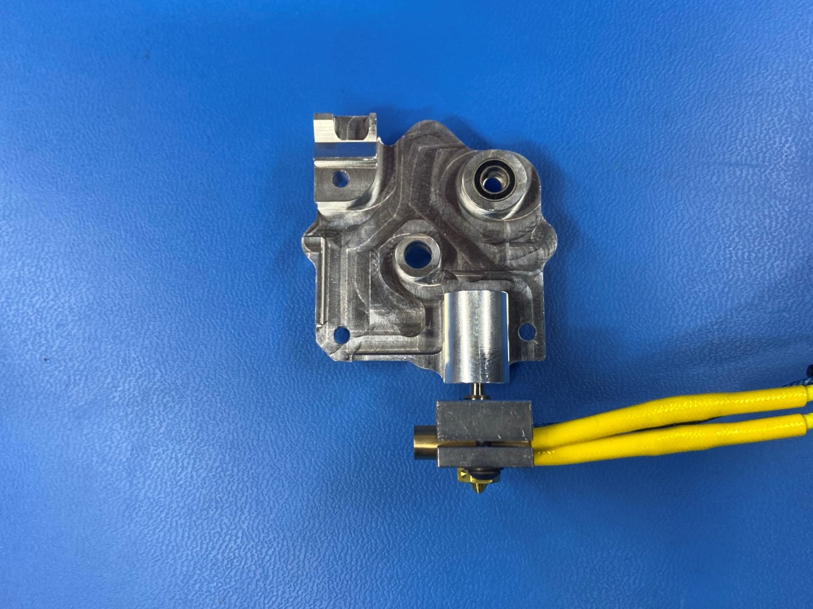
Then repeat process with the heatsink assembly and place a bearing inside the hole on the heatsink as shown.

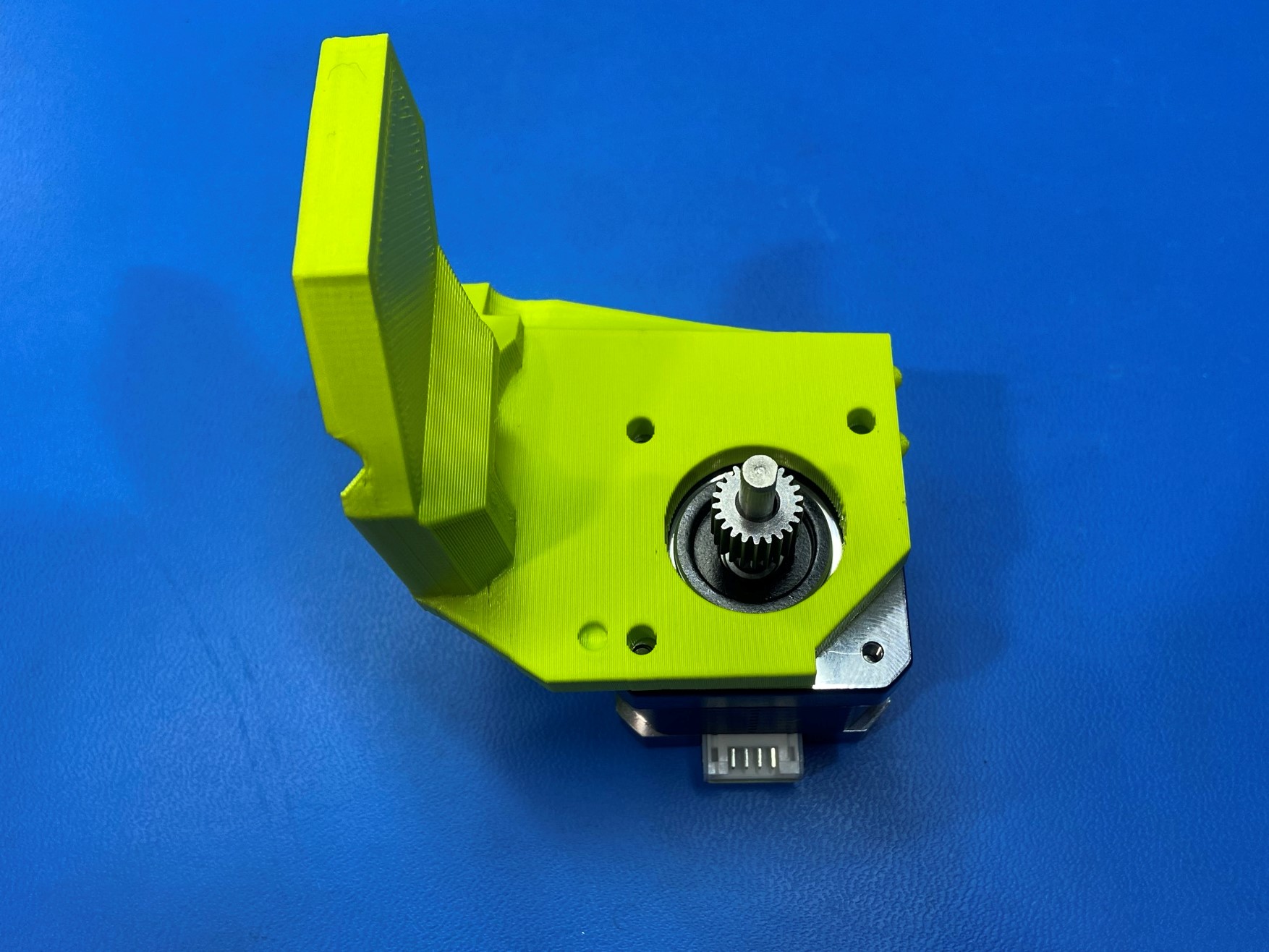
Take the stepper motor with gear and place the 1.75 extruder mount [PP-GP0643] over the motor as shown. Make sure the motor connector is facing you and have the tall side of the extruder mount on the left.
Then place the aero body over the extruder mount as shown.
Use 1x M3 lock washer [HD-WA0027] and 1x M3x12 BHCS [HD-BT0146] to secure the extruder mount and aero body to the motor. Use the bottom left hole.
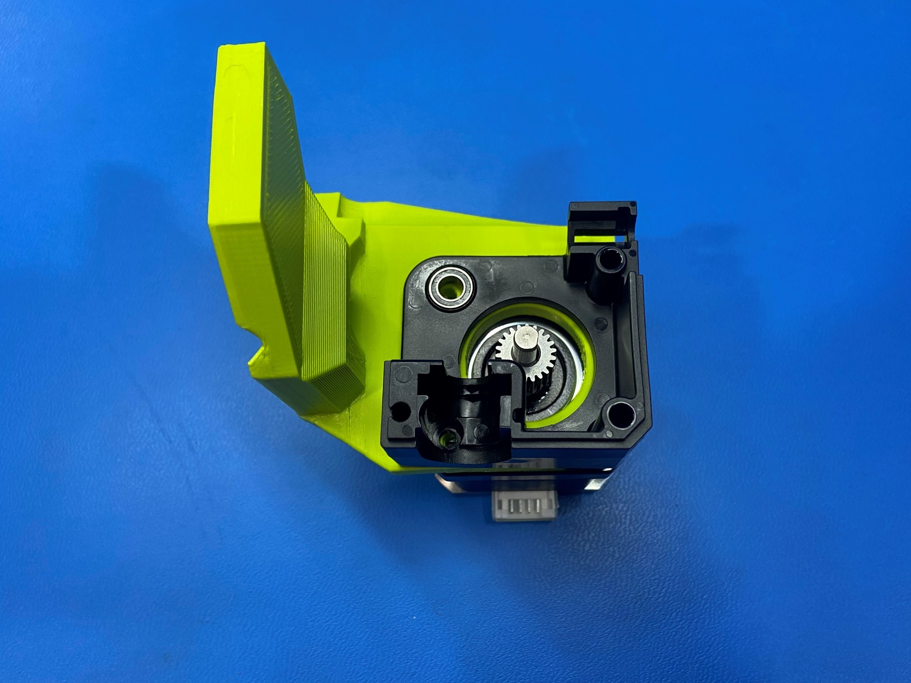
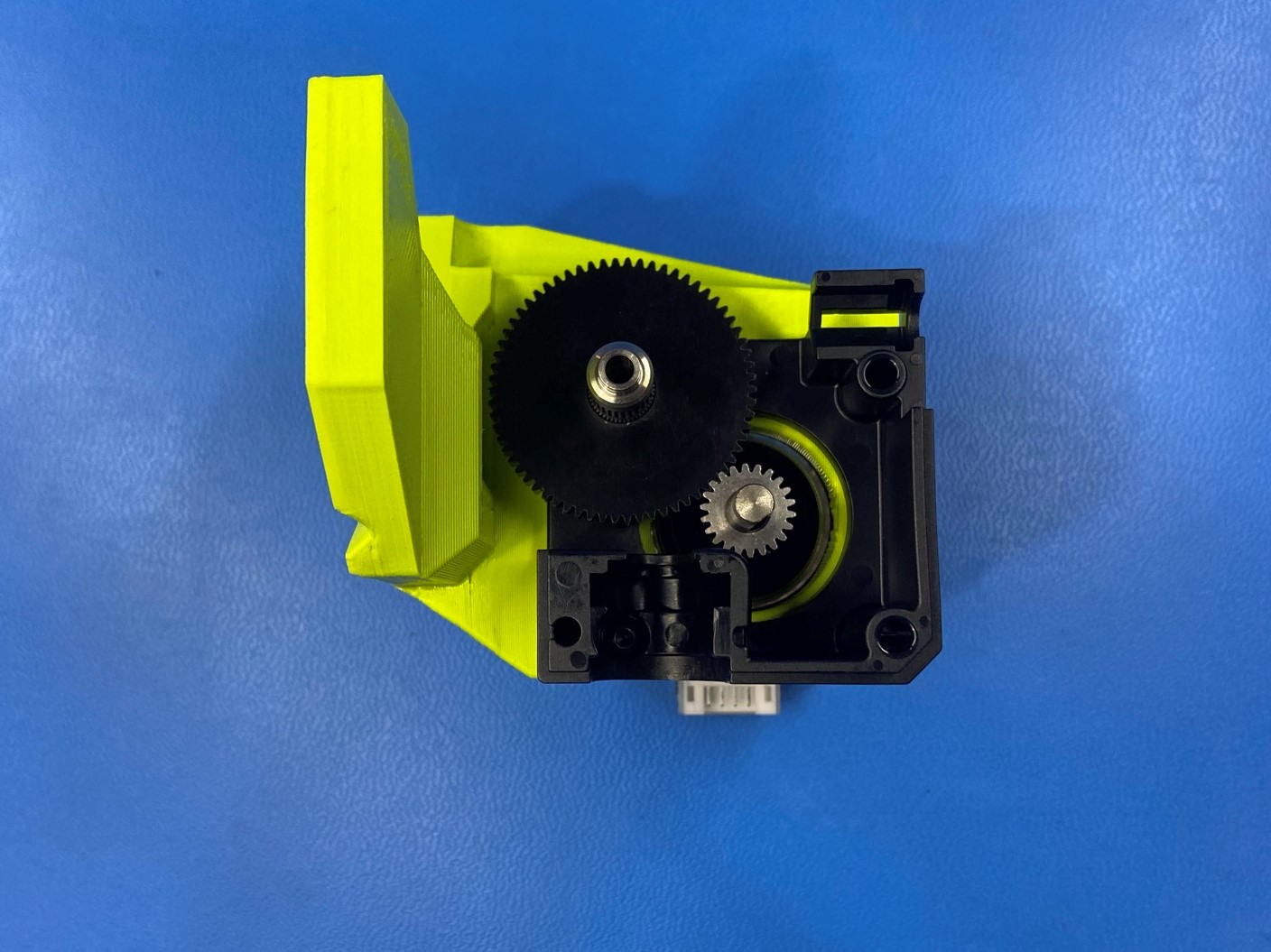
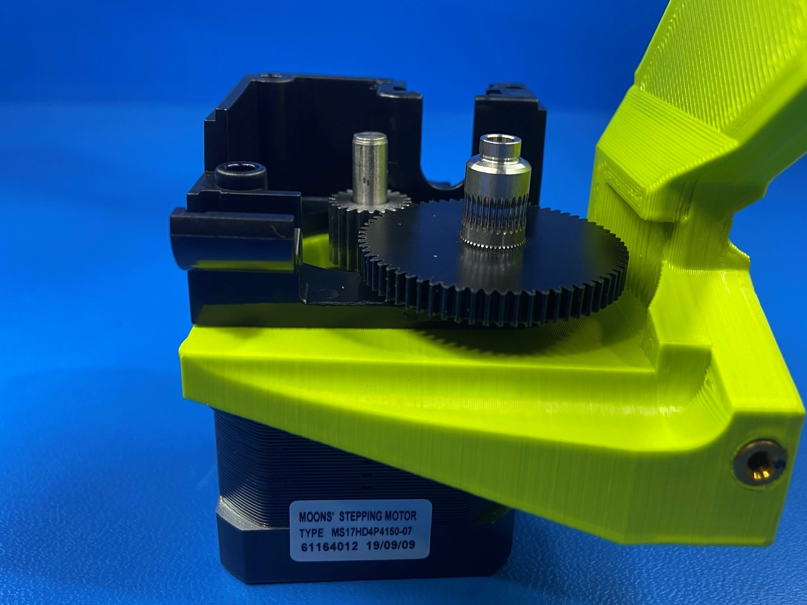
Install the filament drive shaft [PP-FP0137]. Make sure the faces of the two gears are flush with each other. Adjust the pinion gear as necessary. If adjustments are required, make sure to re-torque the pinon gear set screw.
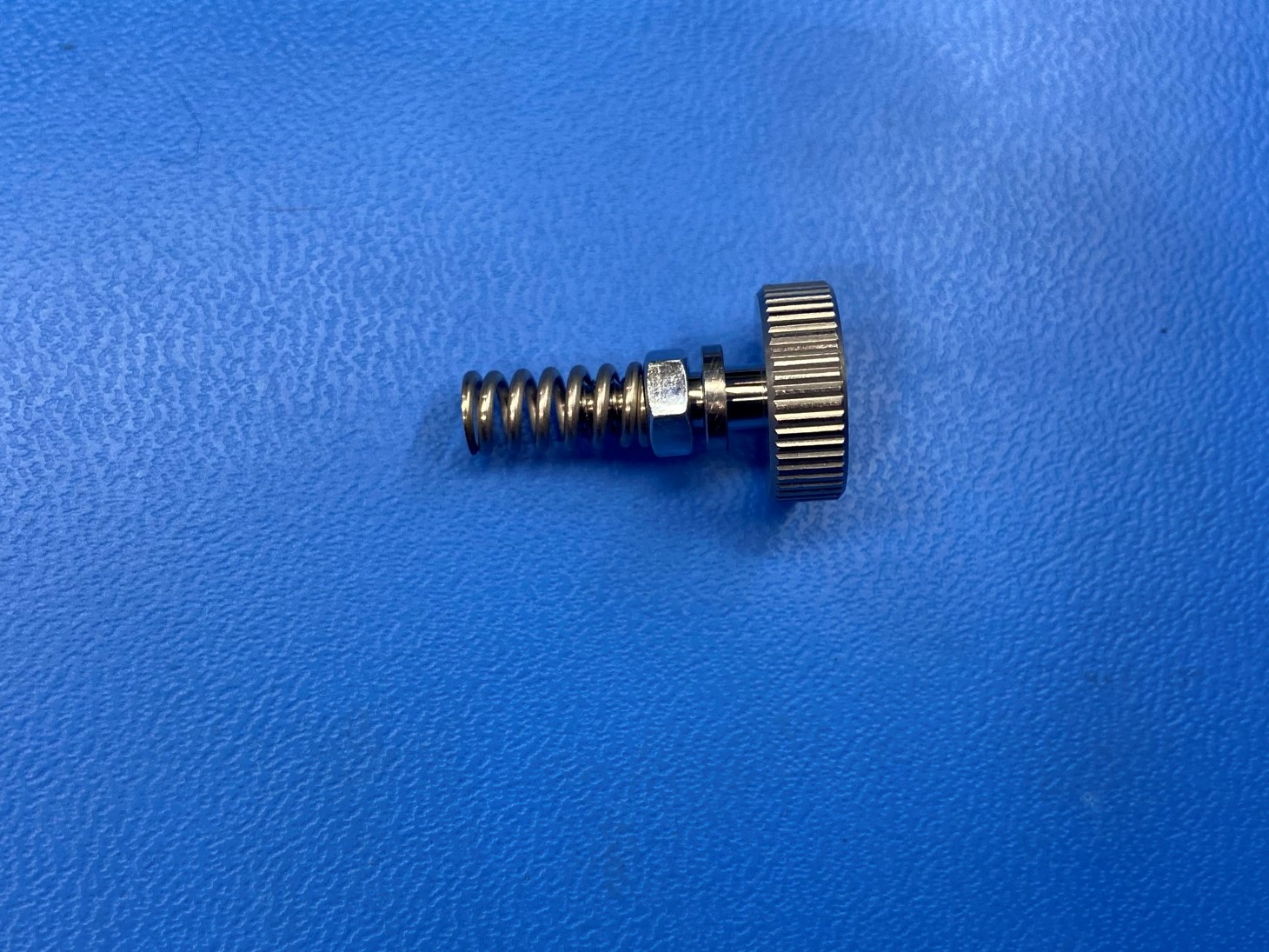
Thread one M4 nut [HD-NT0011] onto the M4 thumb screw [HD-BT0197] and then place a idler spring onto the end of the screw.
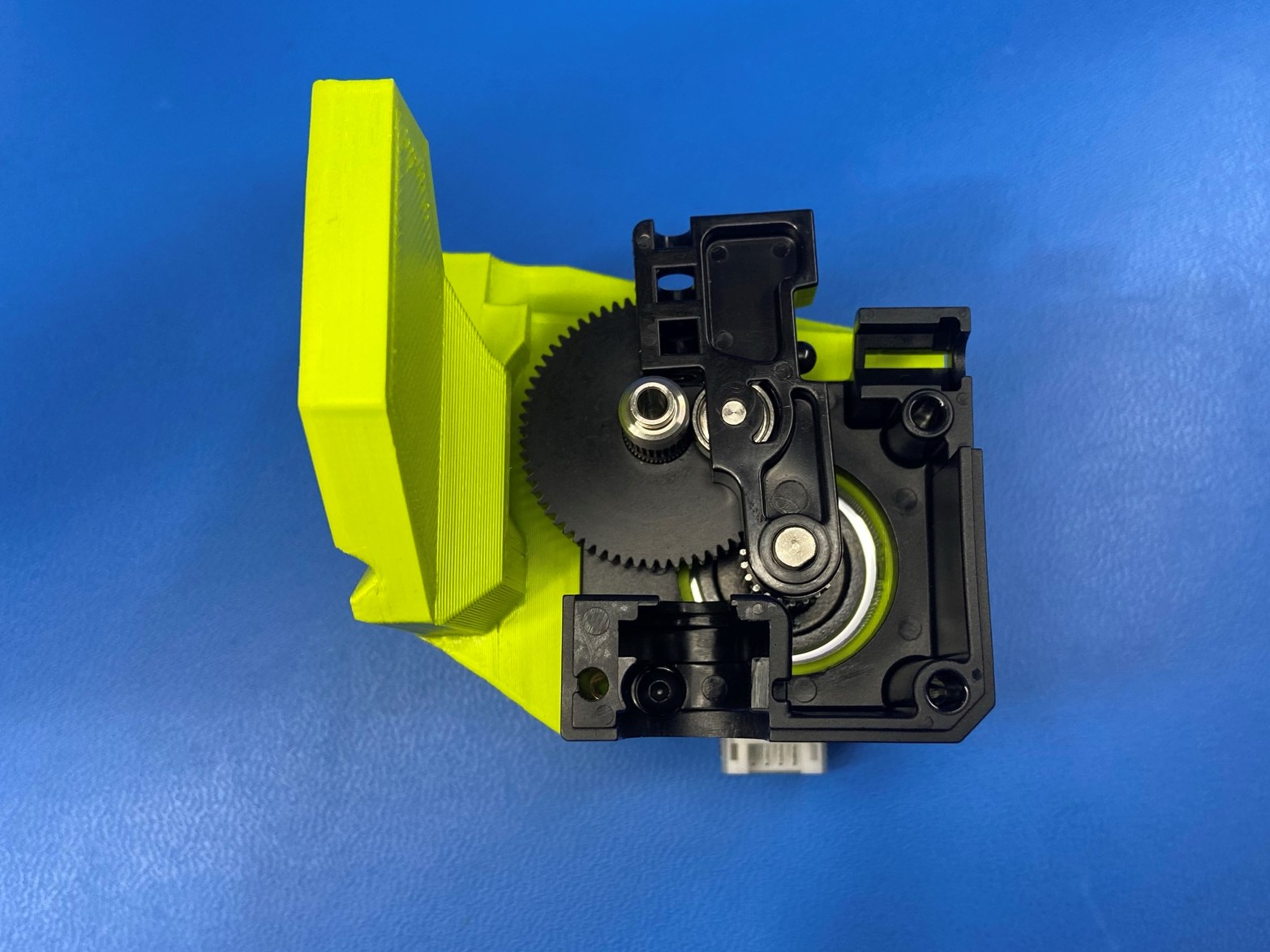
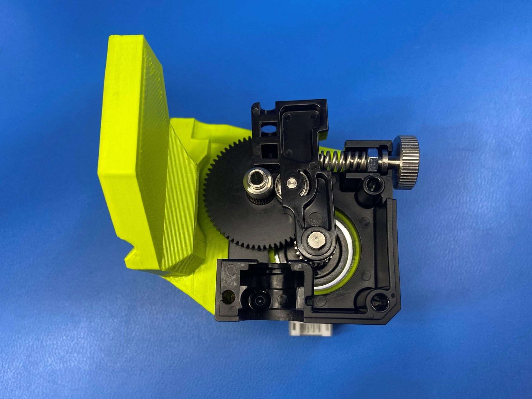
Install the idler lever [PP-FP0135] and the idler spring assembly onto the aero body.
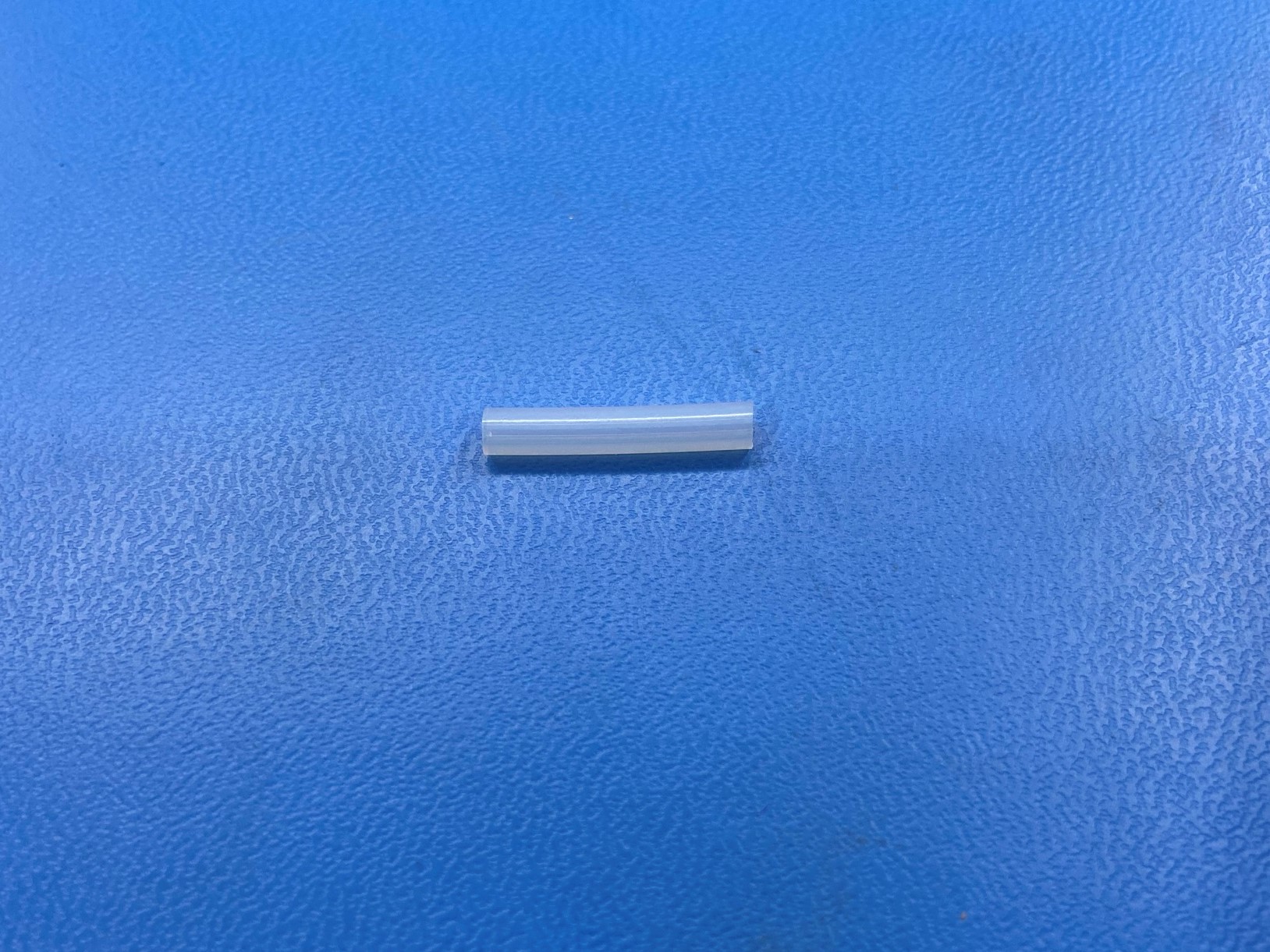
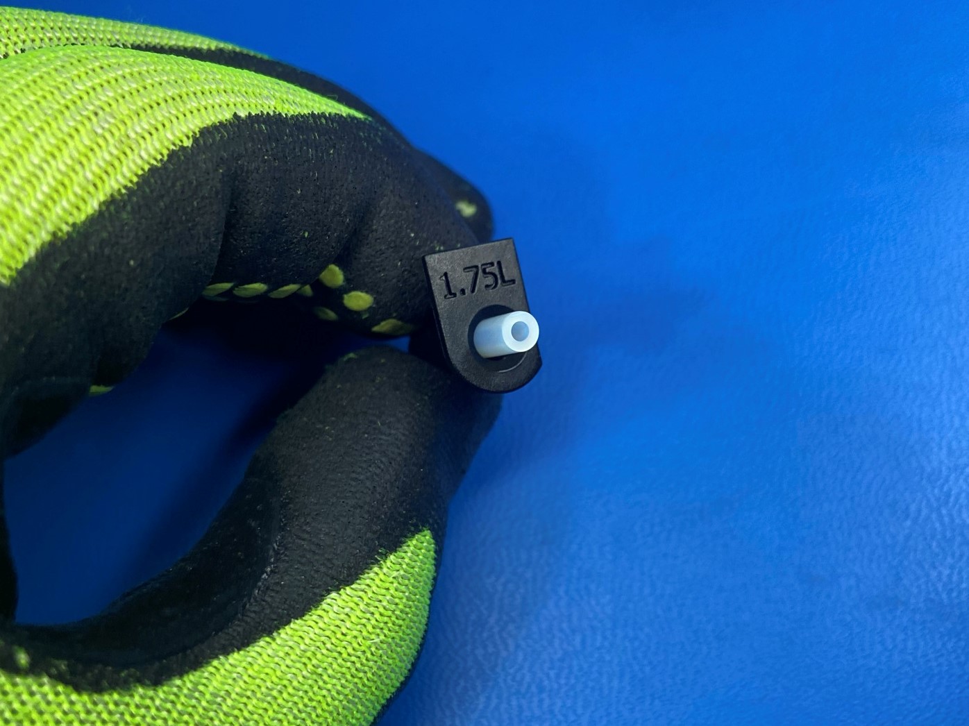
Take a 20mm section of the feed tube [HD-TB0080] and slide it inside the 1.75 filament guide [PP-FP0219] make sure to slide it in from the flat side, half should be sticking out.
Then slide the other side into the heatsink making sure to align the base of the filament guide with the face of the heat sink.
Place the heatsink over the aero body making sure the drive shaft aligns with the bearing on the heatsink.
Next connect the extruder motor harness [AS-CB0061] to the motor.
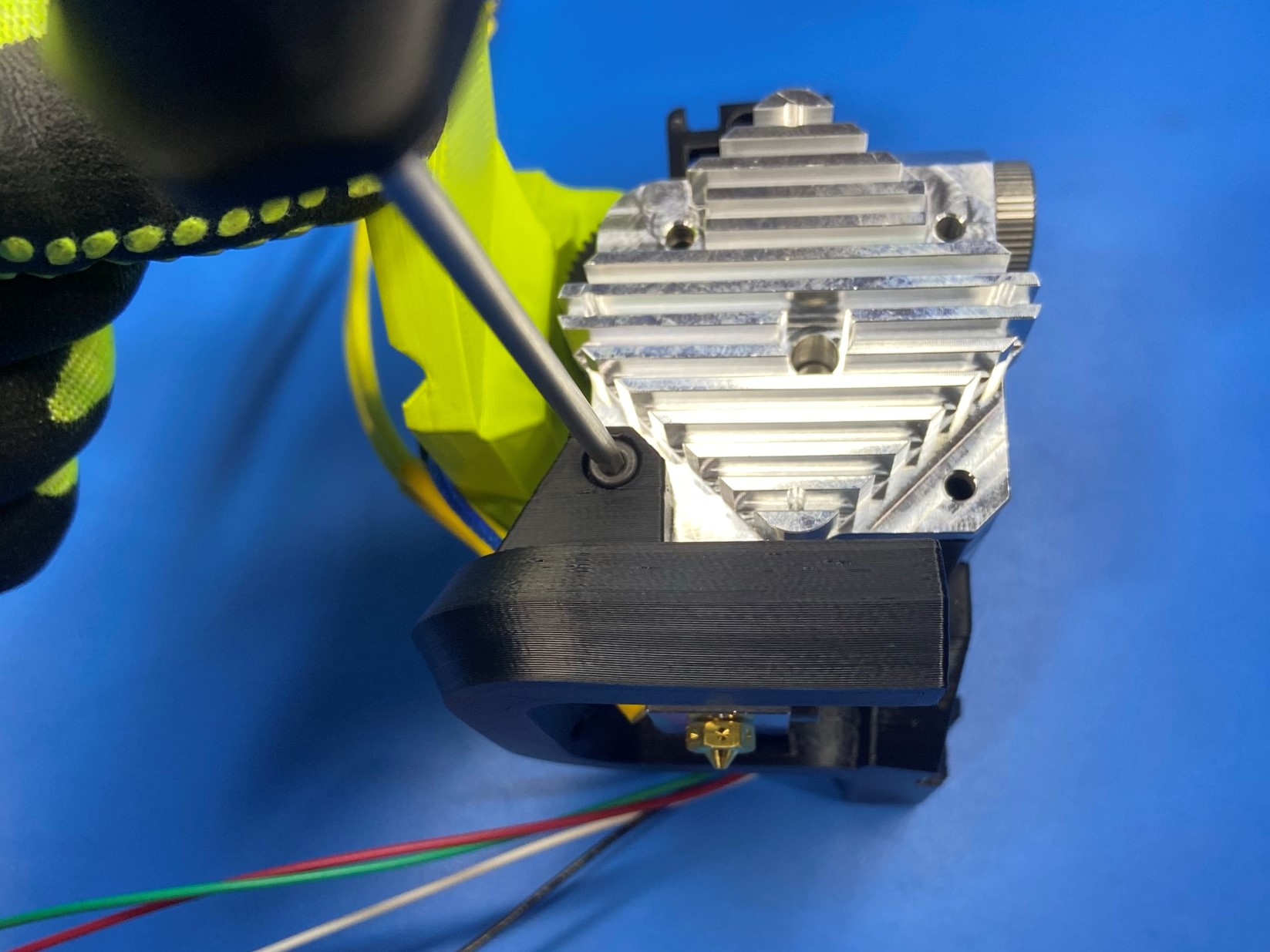
Then slide the 1.75 SK blower shroud [PP-GP0642] around the assembly and use 1x M3x30 SHCS [HD-BT0042] in the bottom left hole to secure the blower shroud to the assembly.
Now use 3x M3x35 SHCS [HD-BT0043] to fully secure the blower shroud, heatsink, aero body, and motor.
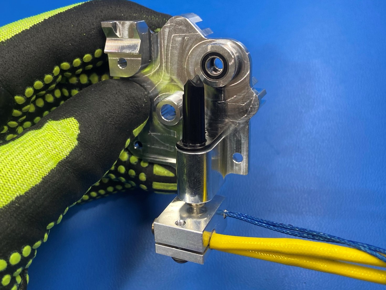

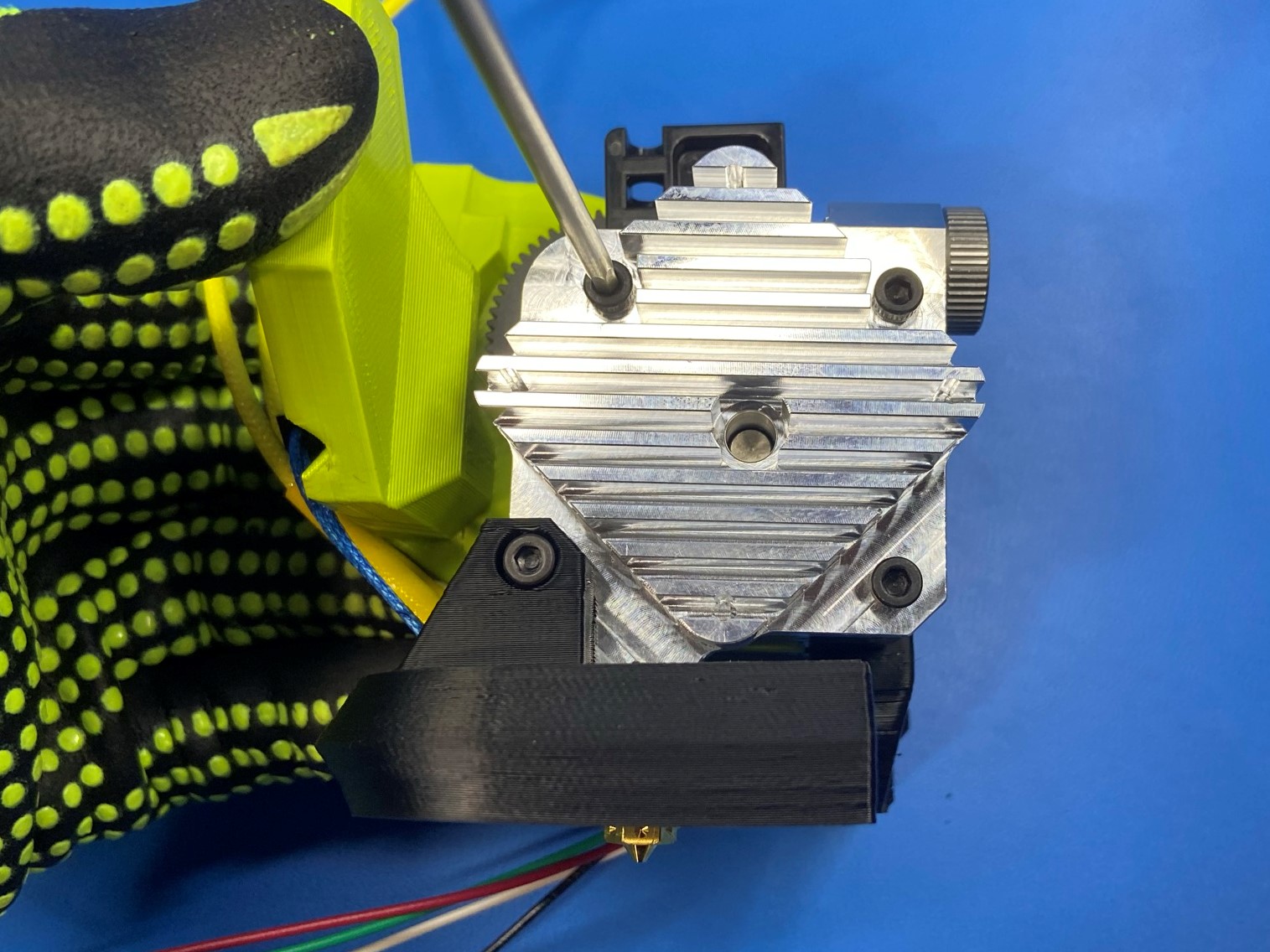
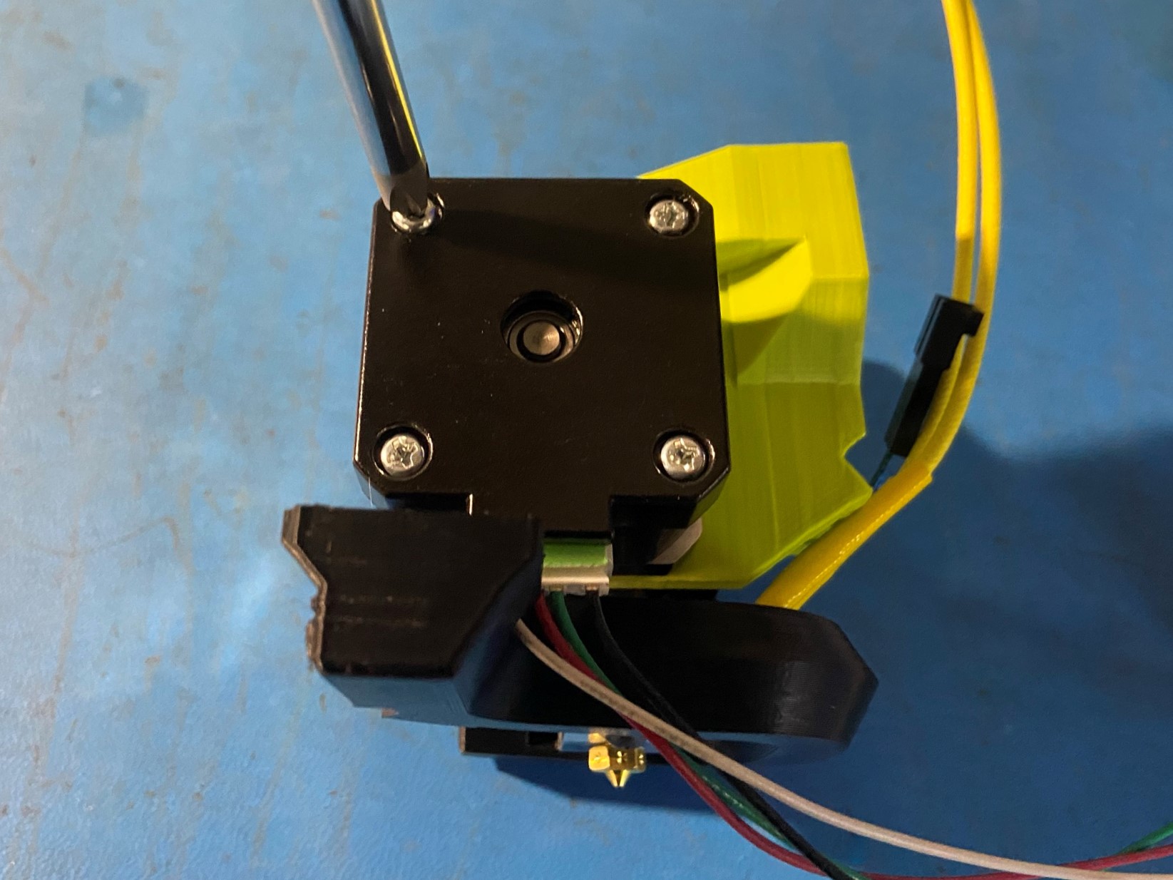
Rotate the assembly so that the back of the motor is facing you with the blower shroud on the bottom side and remove the top left screw from the motor.
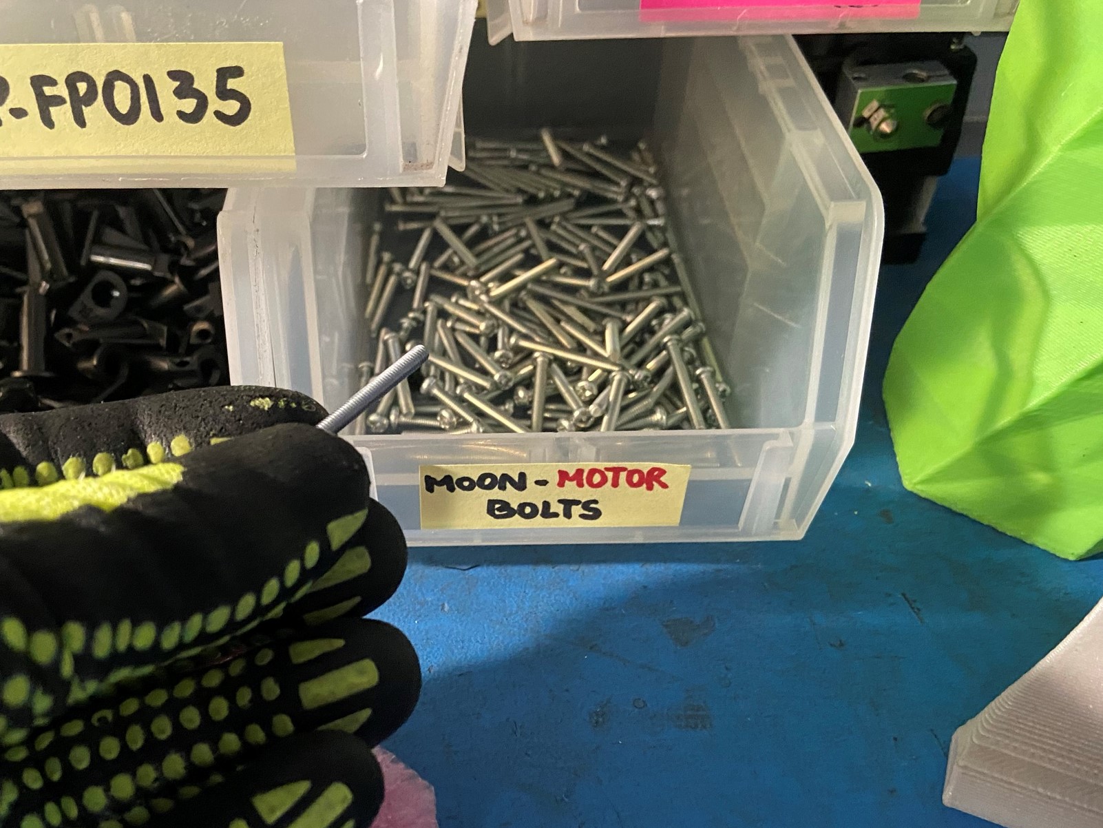
Once the screw is removed place it in the Moon's Motor screw container.
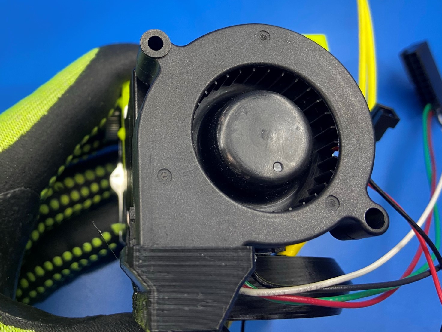
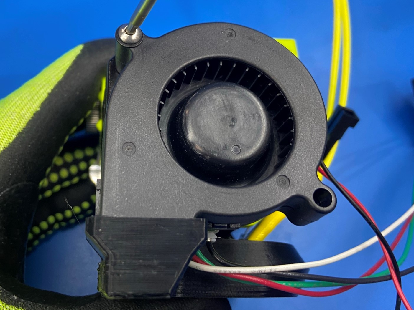
Then place the rectangular side of the blower fan [AS-CB0112] inside the rectangular hole on the blower shroud.
Now using 1x M3x45 BHCS [HD-BT0273] and 1x M3 washer [HD-WA0038] secure the blower fan to the motor.
Once the blower fan is secure place the caution hot sticker [DC-LB0155] on the blower fan.

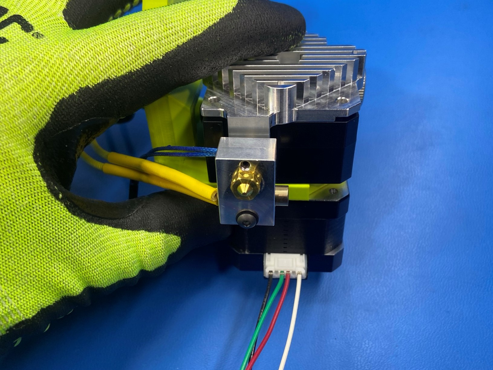
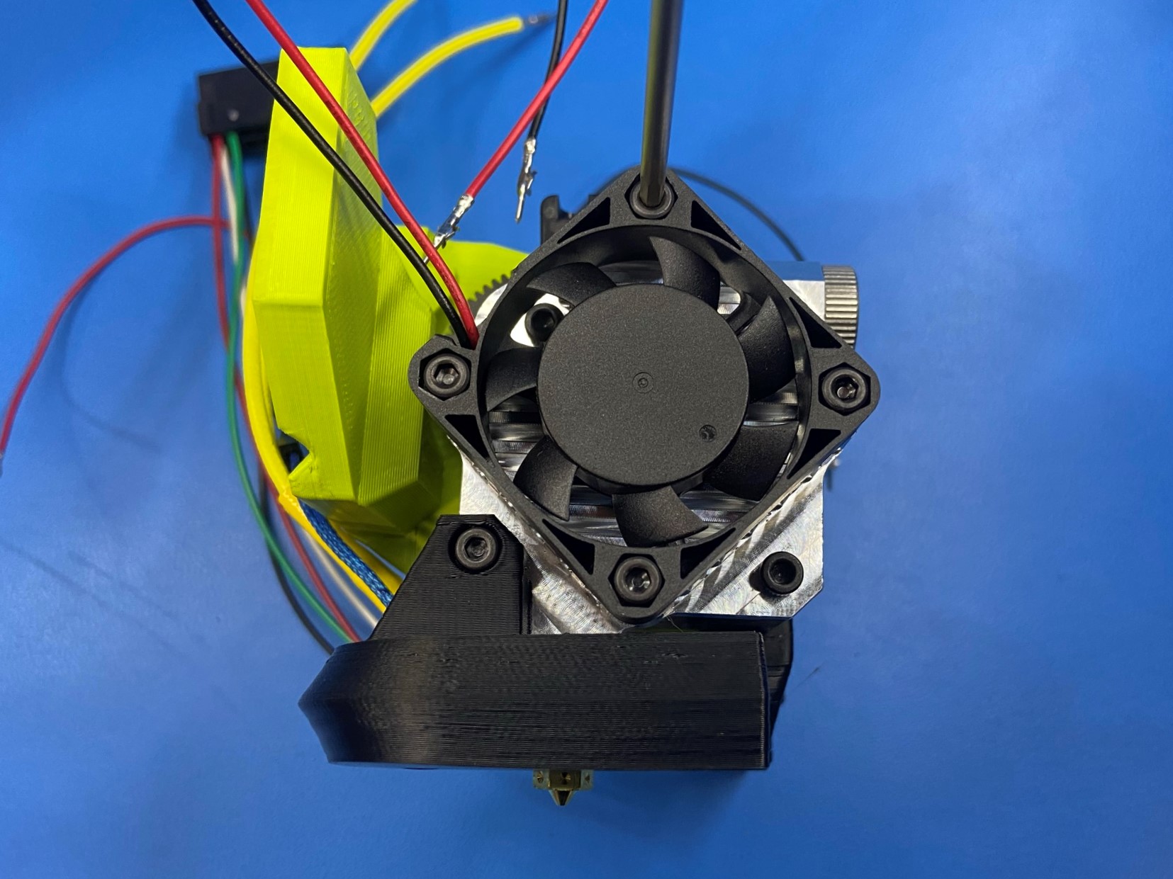
Rotate the tool head so that the heatsink is facing you with the blower shroud on the bottom, and place the heatsink fan [AS-CB0062] on the heatsink with the wires in the top left.
Then using 4x M3x12 SHCS [HD-BT0039] secure the fan to the heatsink.
Connect the thermistor harness [AS-CB0066] to the blue thermistor wire that's attached to the hot end.
Make sure there is a good connection, by gently pulling on the thermistor harness.
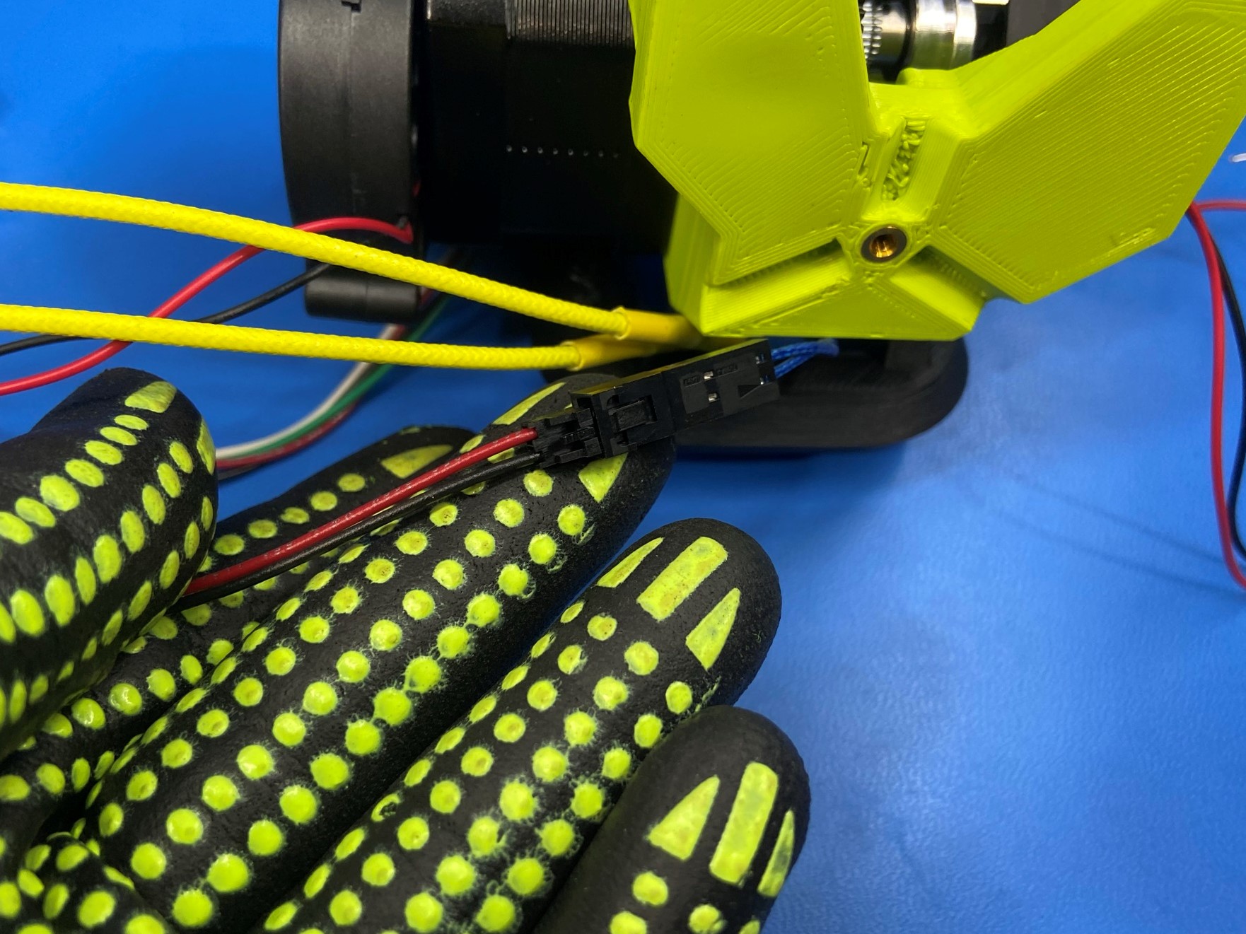
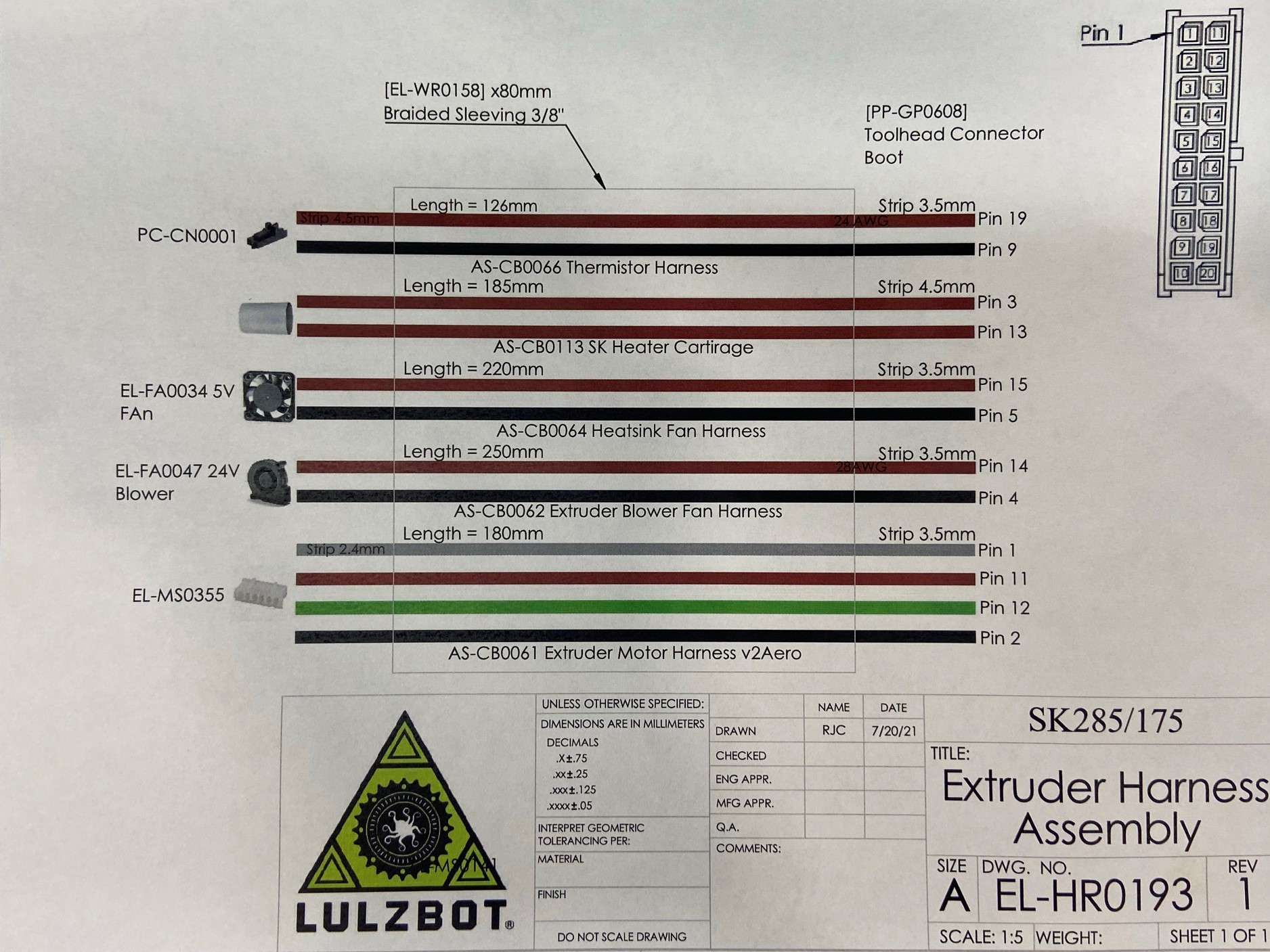
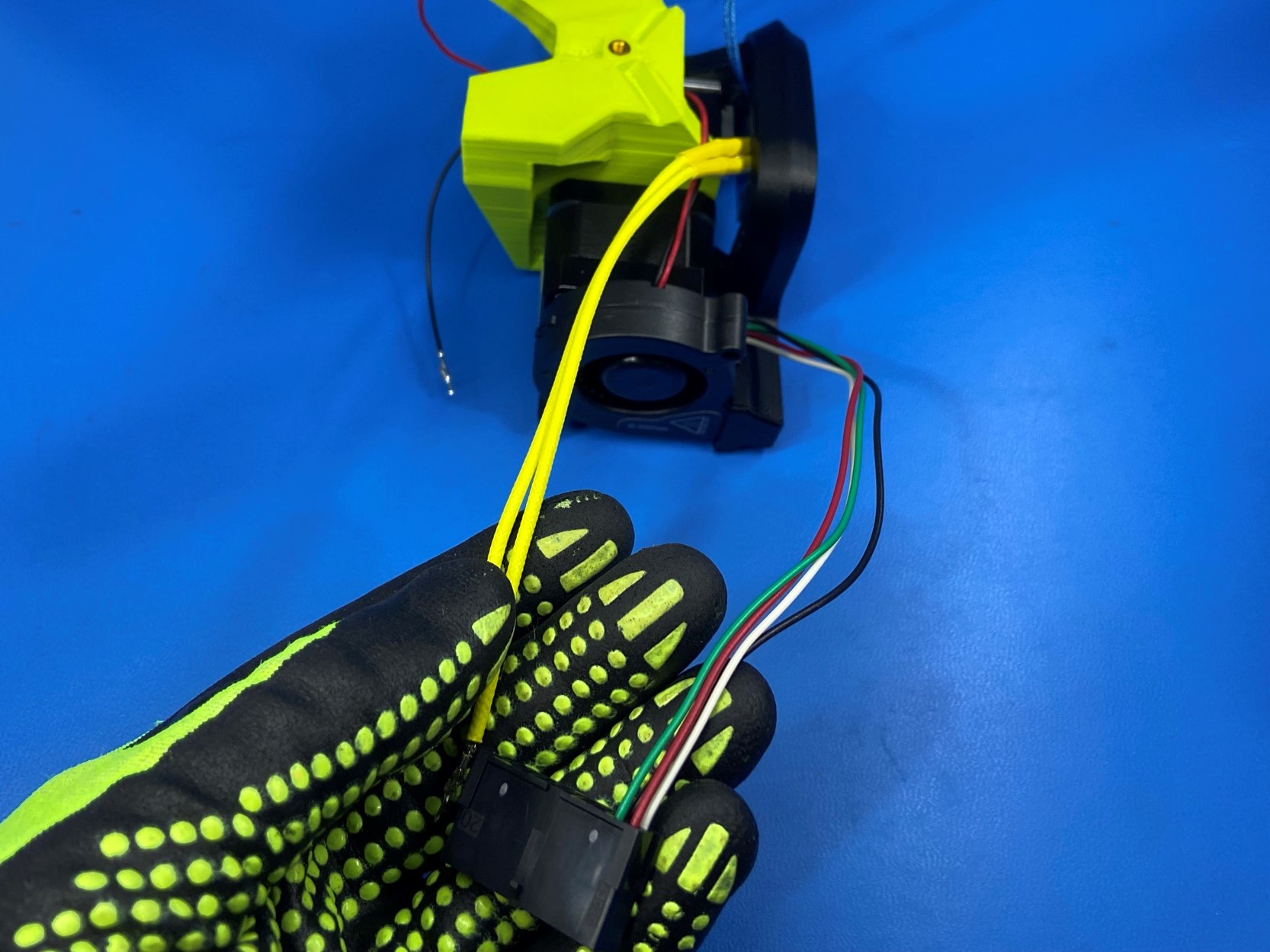
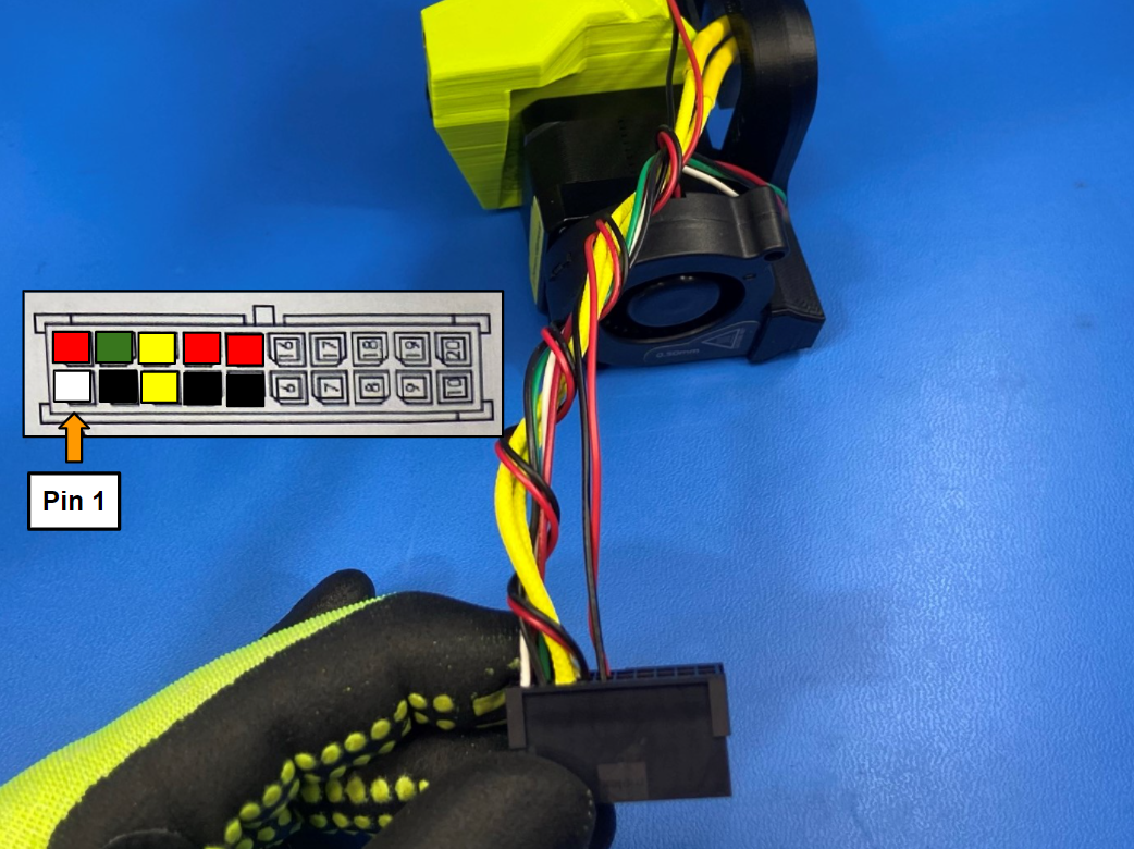
When connecting the wires to the toolhead connector follow the wire placement guide and photos.
Start with the heat cartridge harness this harness could be yellow, white, or red. Once you found it wrap it around the extruder motor harness to remove slack and connect the two wires to the connector next to the black and green wires.
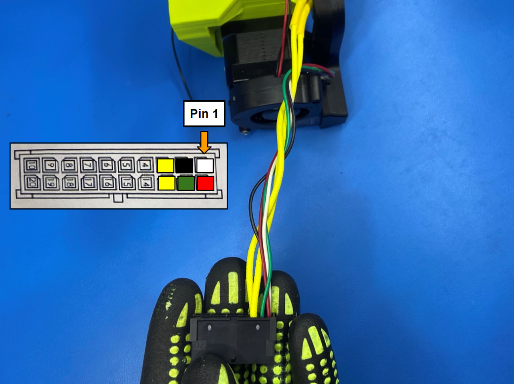
Next find the blower fan harness and repeat process of wrapping the harness around the other harnesses and connect it to the connector with the red wire being closest to the tab on the connector.
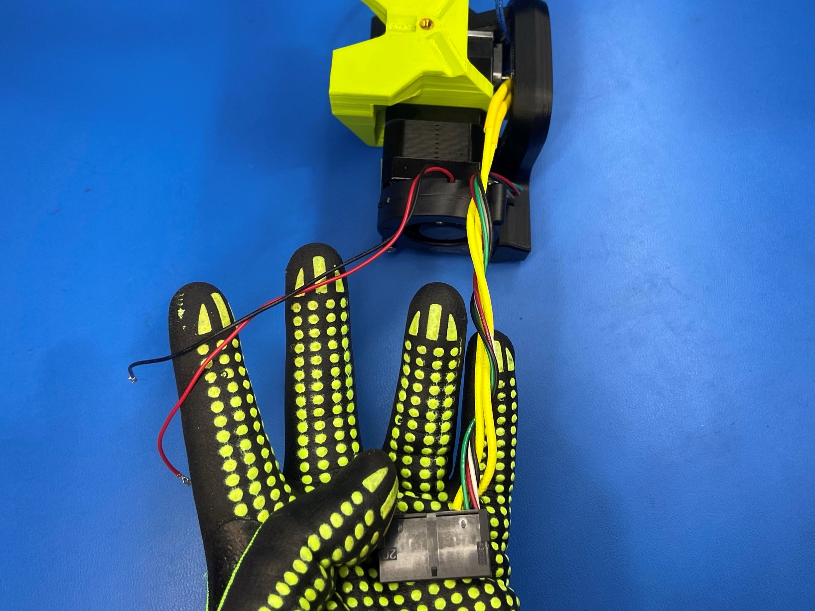
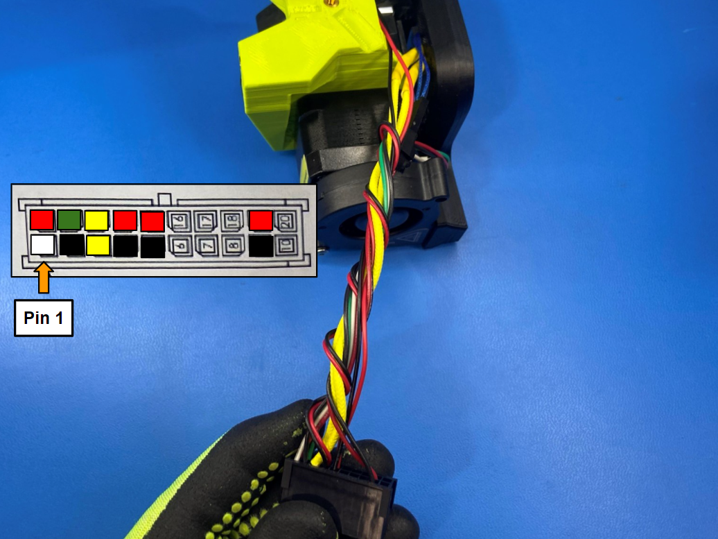
Repeat for the heatsink fan harness making sure the harness is tucked under the extruder mount. Connect it next to the blower fan harness.
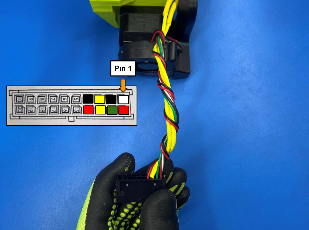
Using the same process for the thermistor harness, wrap then connect red wire to pin 19 and black wire to pin 9 these should be in the second to last row on the connector.

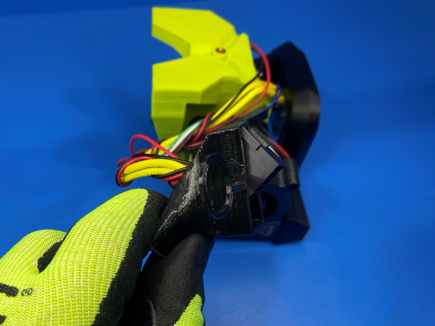
Slide the Toolhead connector boot [PP-GP0608] over the connector.
Start by pushing the side of the connector that has the least wires through the boot then rotate the other side through.
Once the toolhead boot is over the harness have the loop end of the boot on the other side as the tab on the toolhead connector and slide boot around the connector.
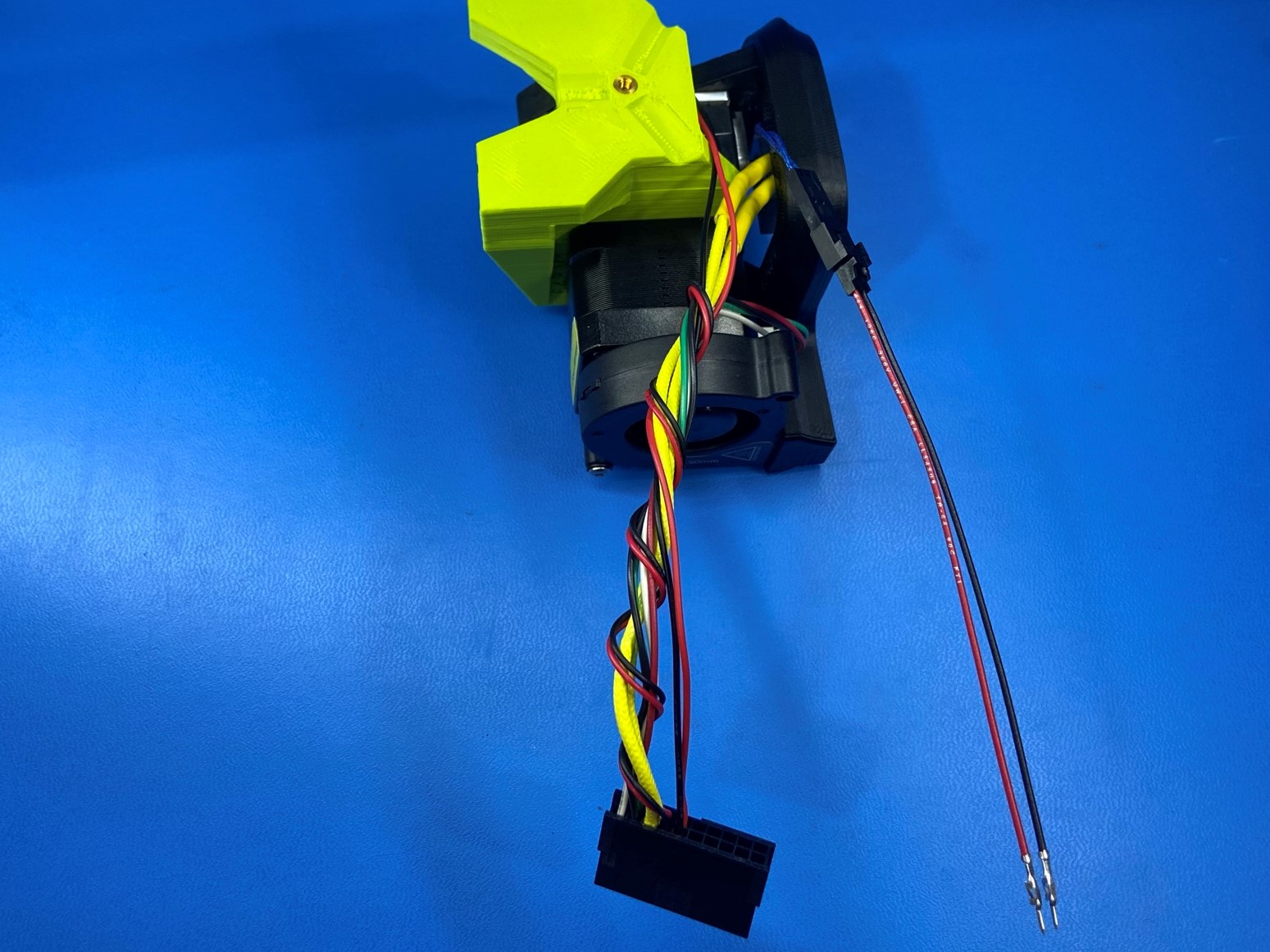
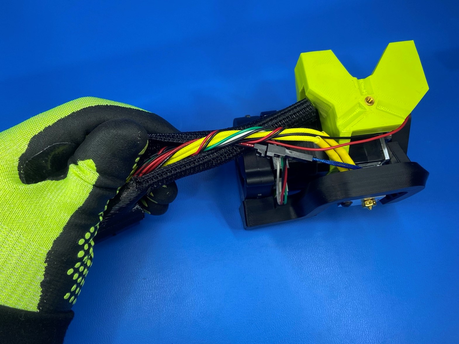
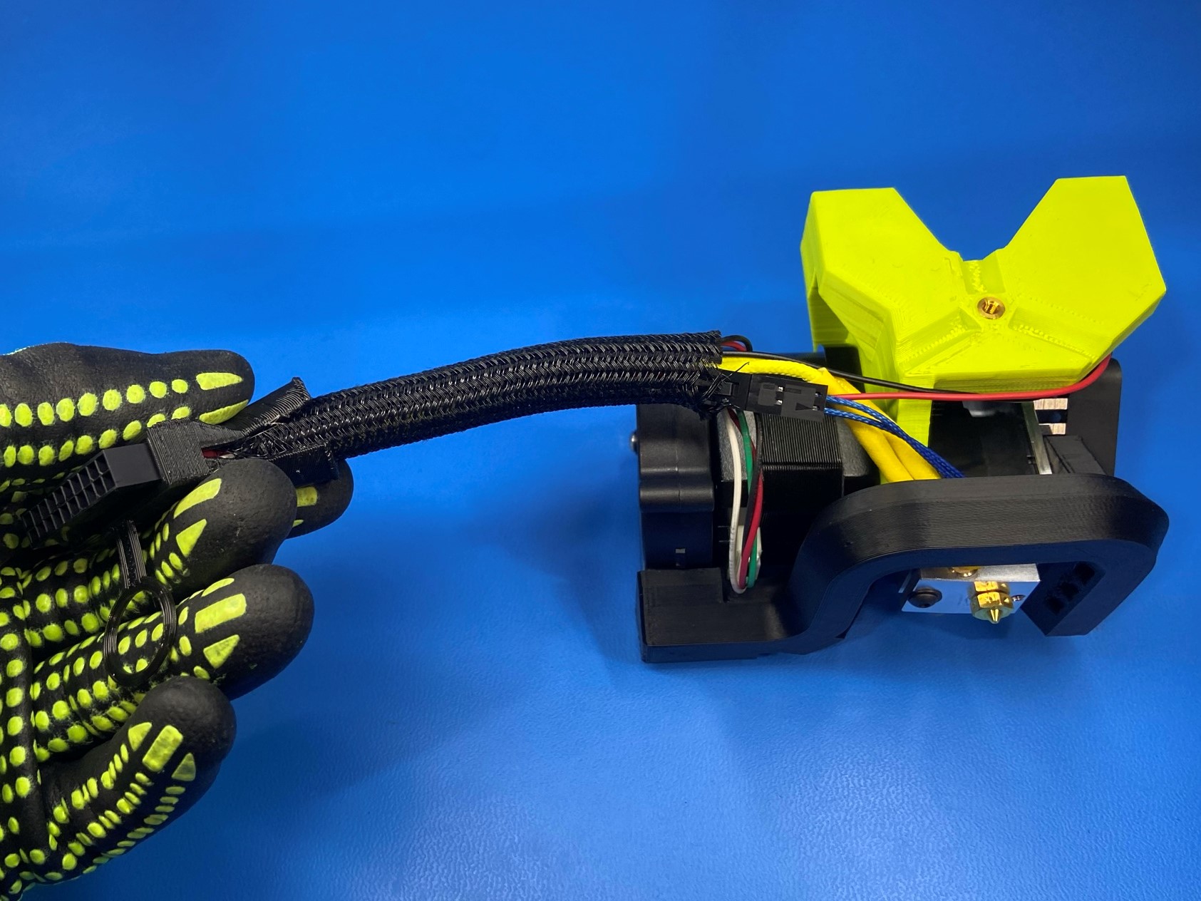
Open one end of the 3/8" self-wrapping braided sleeving [EL-WR0158] and slide it around the toolhead wires.
Then slide the braided sleeving around the rest of the wires and position it in the middle of the wires.
Install 2x 8" wire ties [HD-MS0058] at both end of the braided sleeving then tighten and trim.


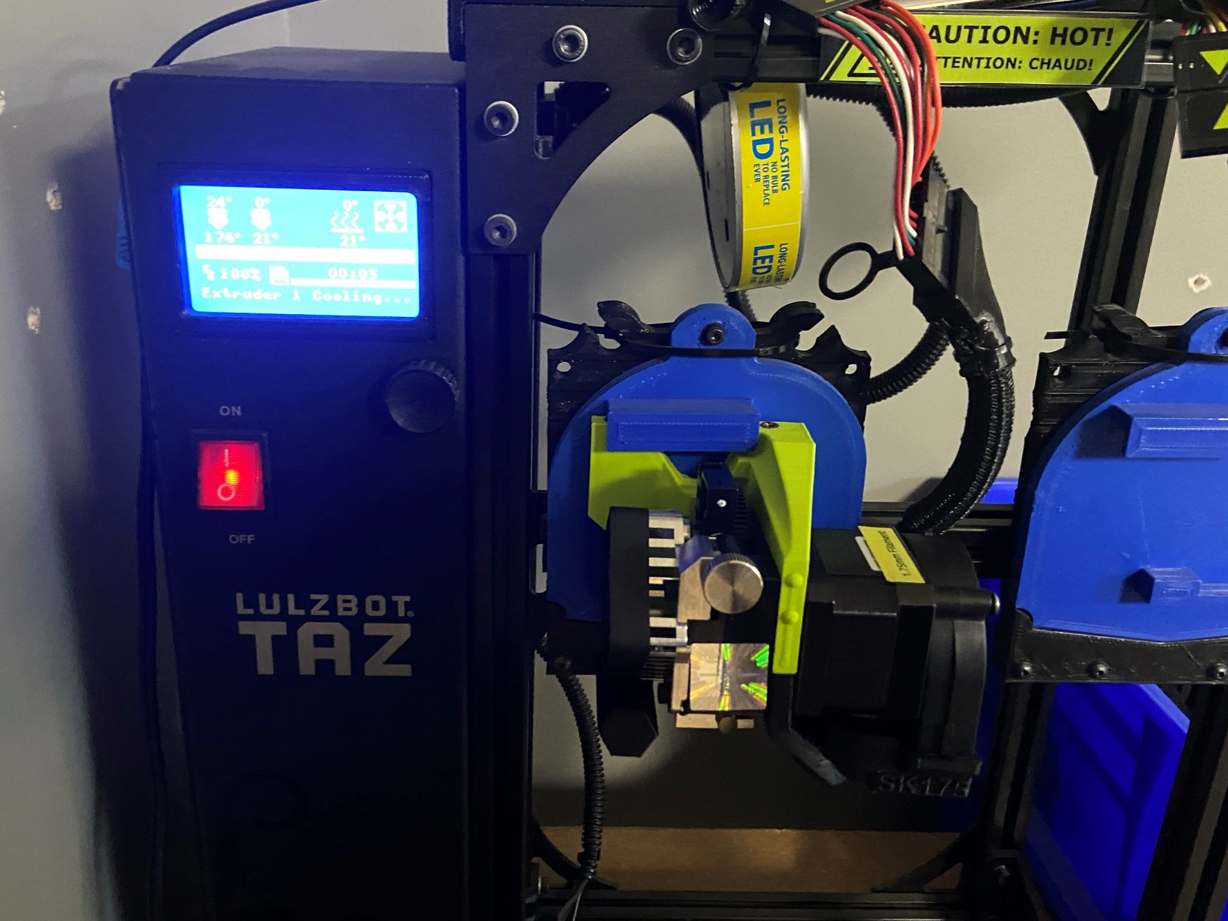
Place toolhead on the testing printer and run the SK 175 test print, this will heat up the toolhead.
Once toolhead has cooled make back of the extruder mount and place in DONE bin.