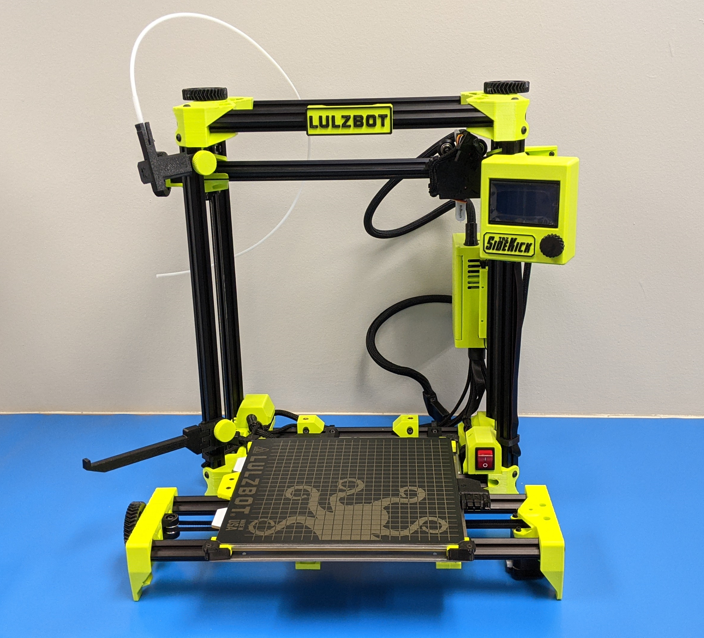
Open HardwareAssembly Instructions
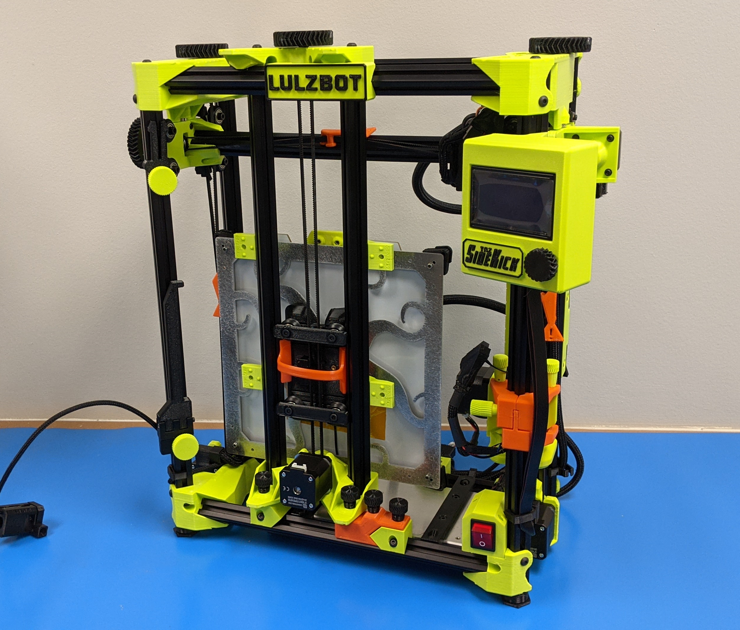
Guides for installation and assembly of the LulzBot line of products made by FAME 3D LLC.
Guides for installation and assembly of the LulzBot line of products made by FAME 3D LLC.
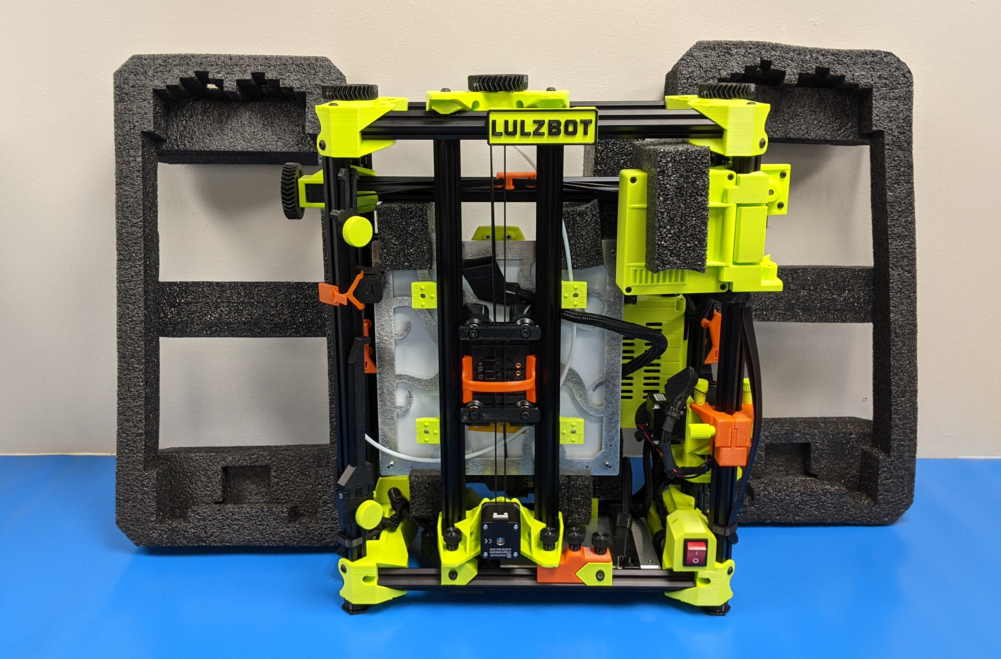
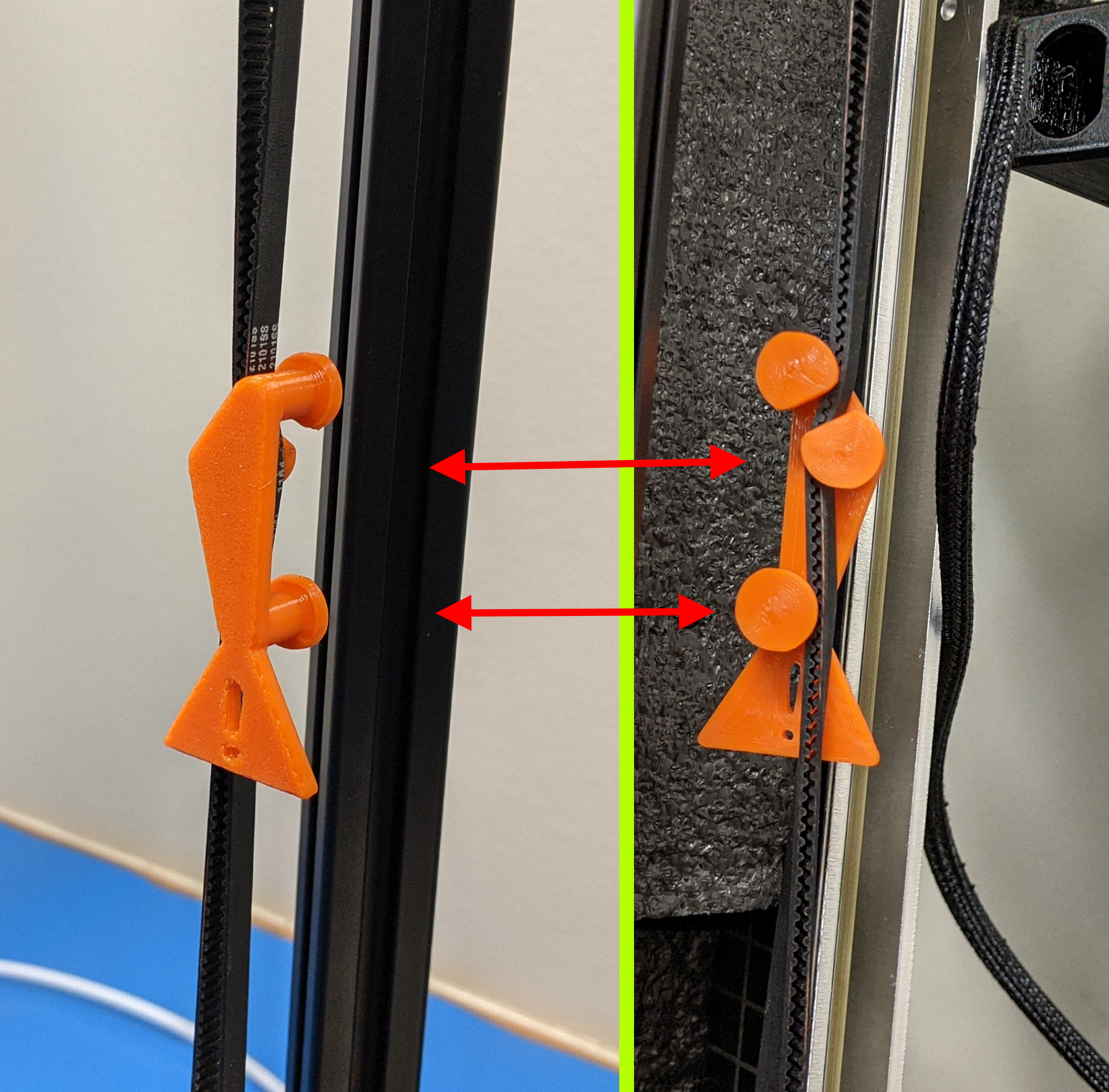
There will be a number of orange parts securing various components to this printer.
Please be sure to keep track of these components as you will want to save them for future use.
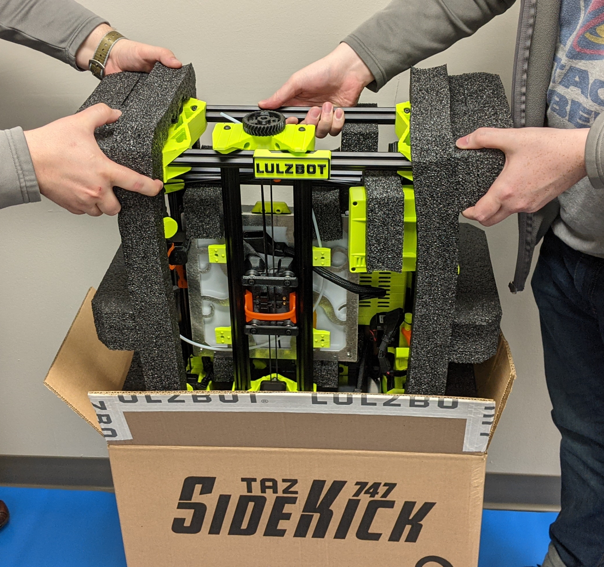
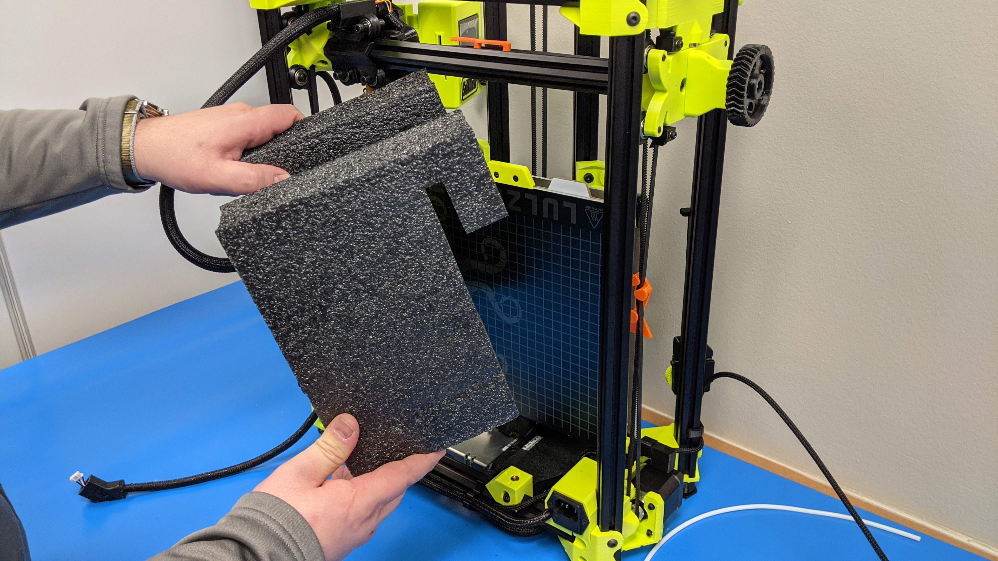
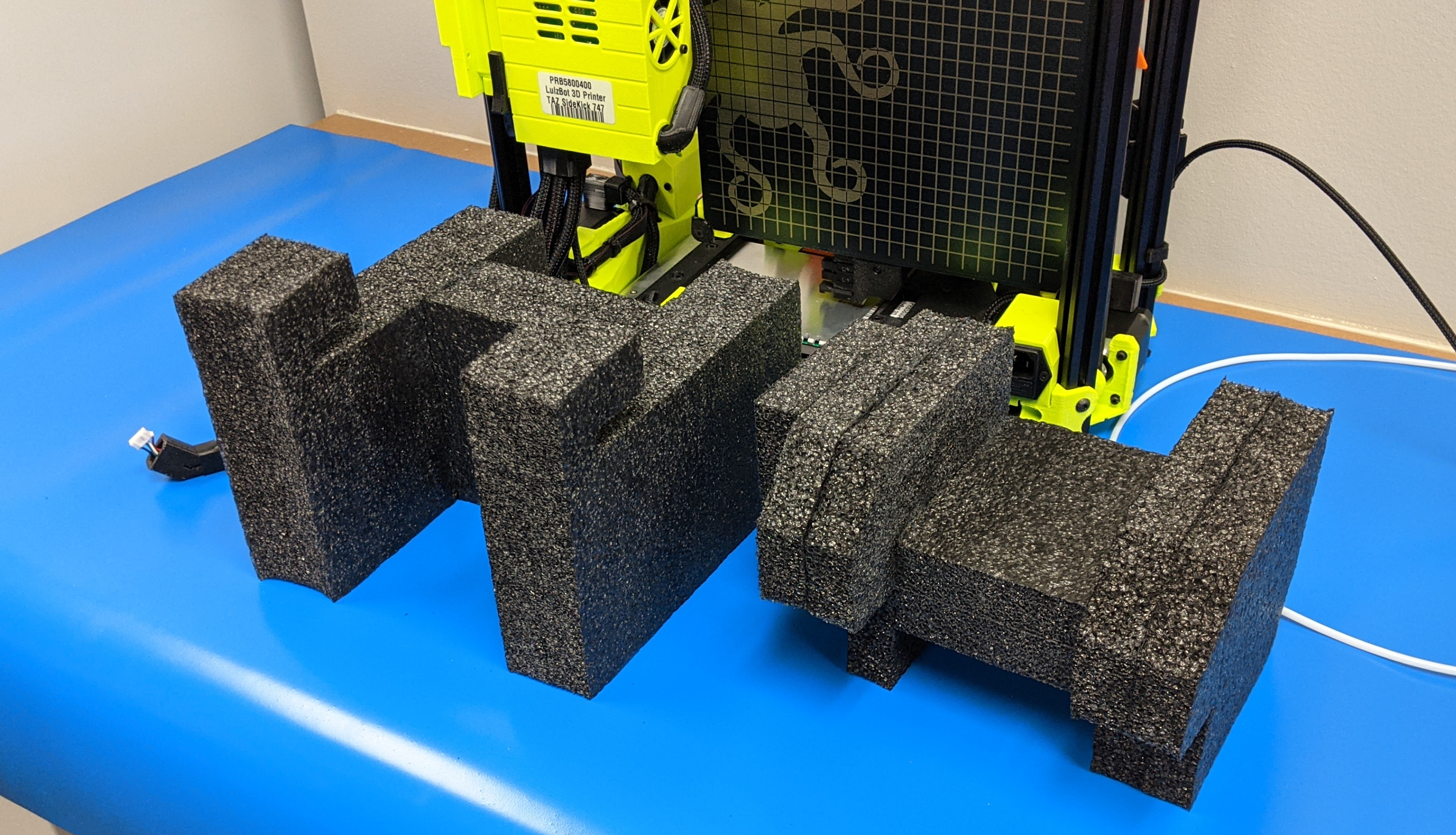
If available, find a helper to assist with removing printer from packaging.
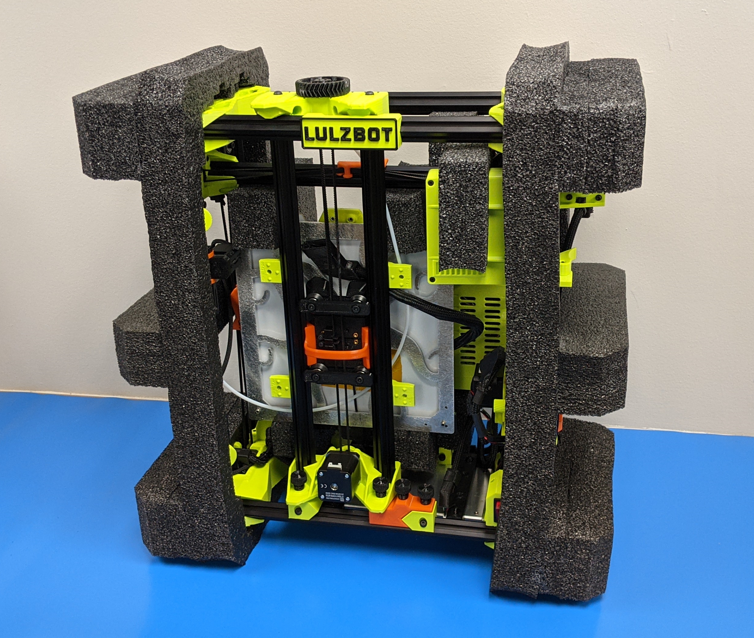
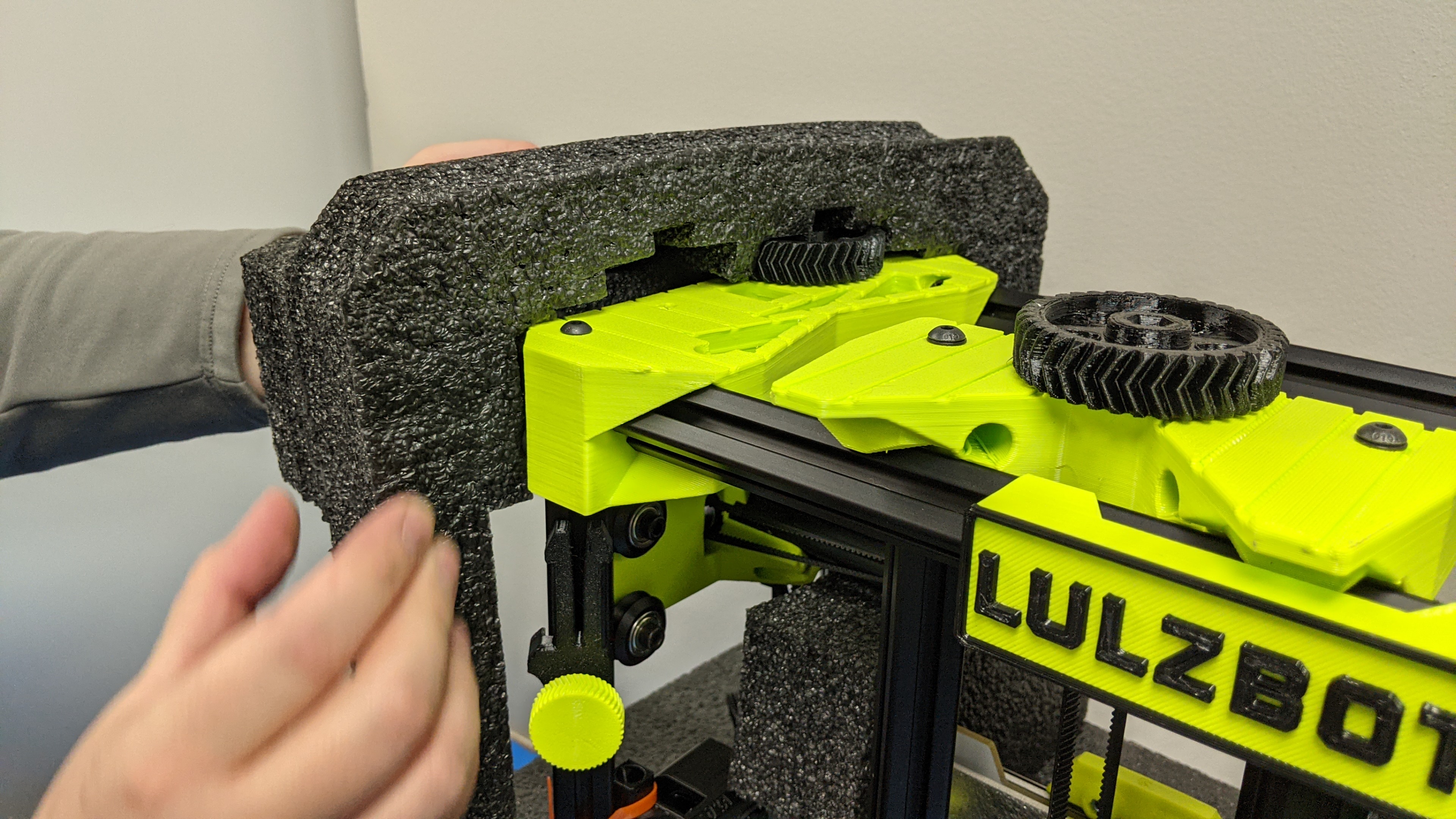
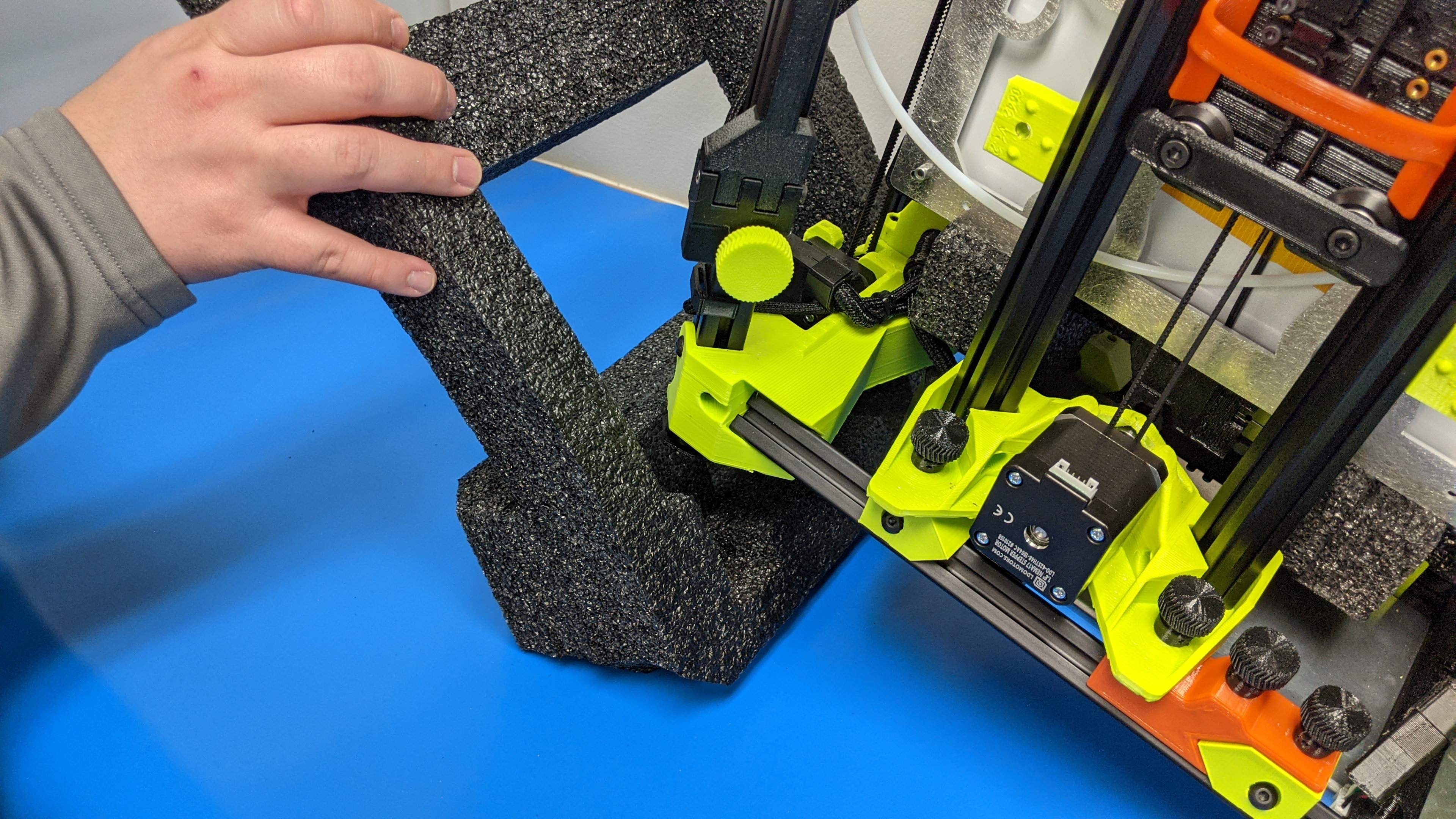
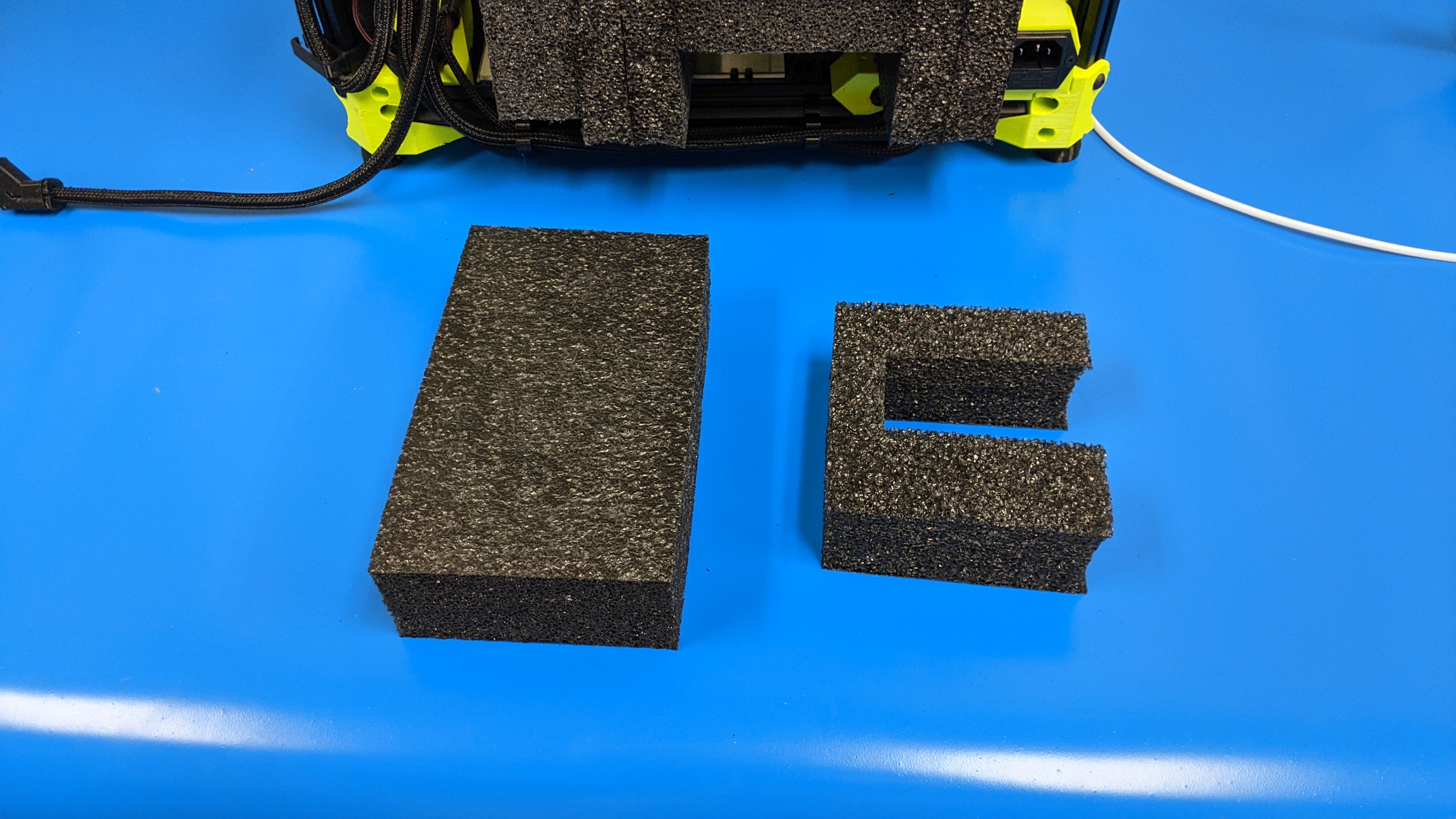
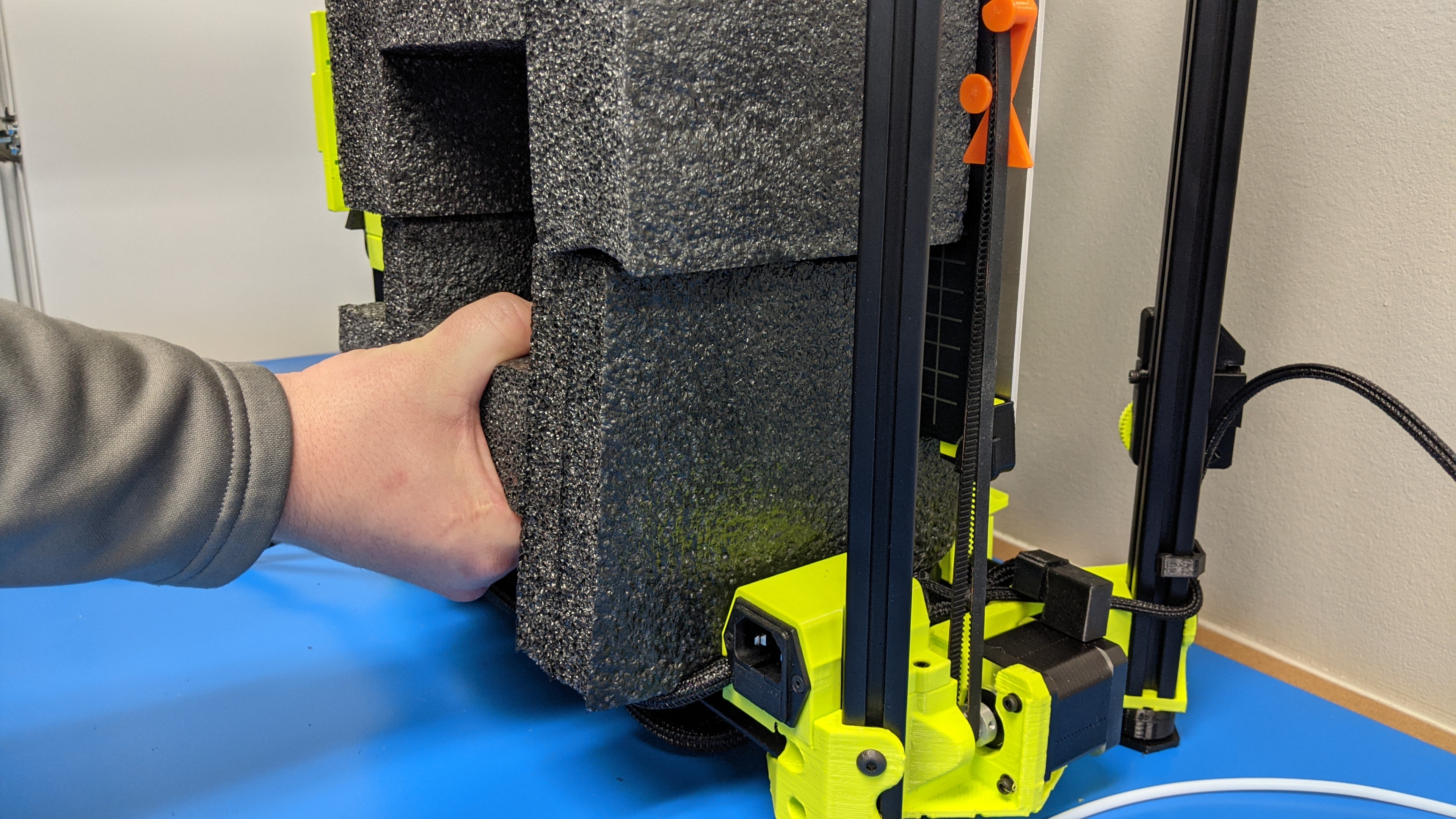
Lift a side of the printer and remove the side foam pieces.
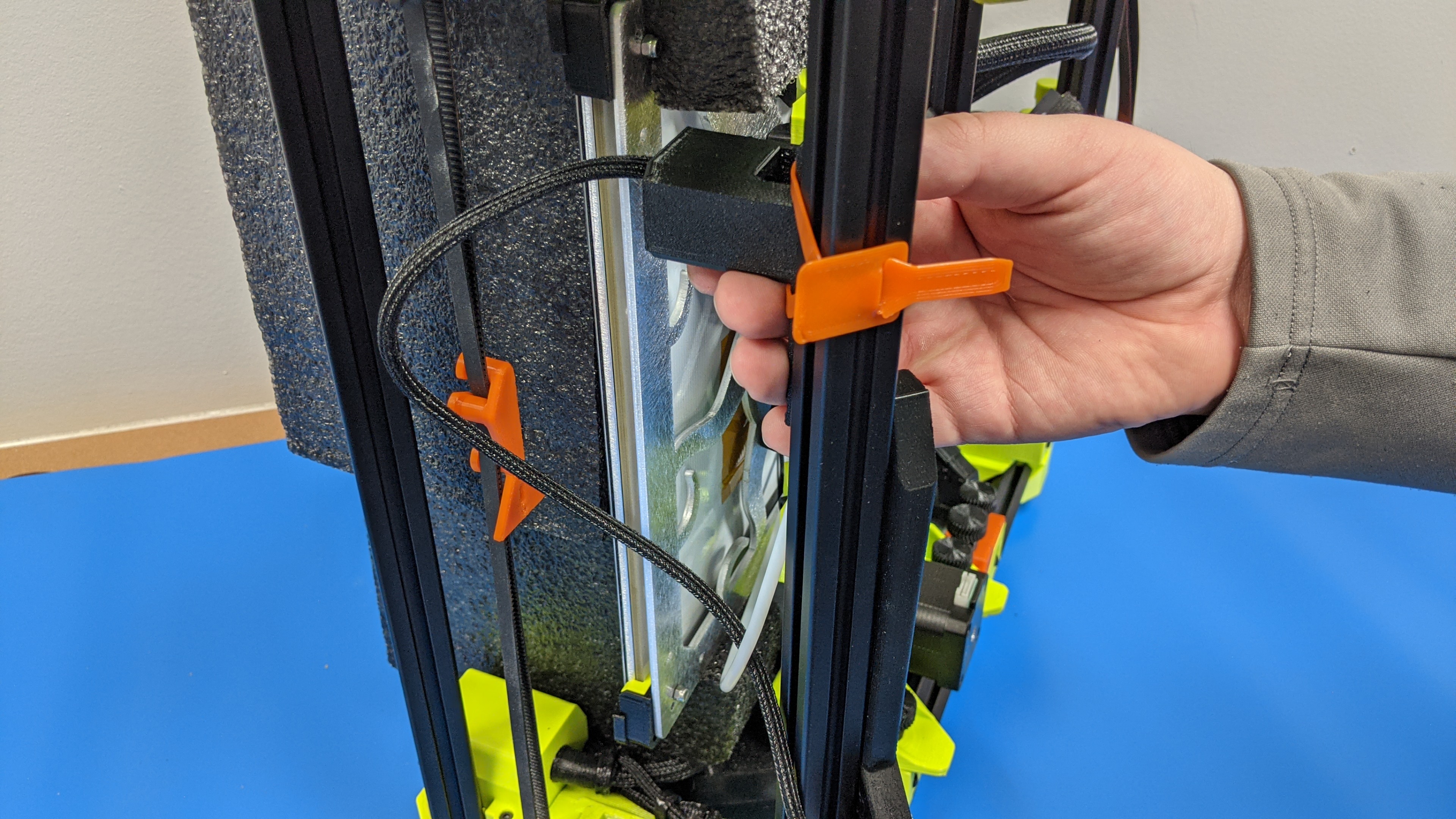
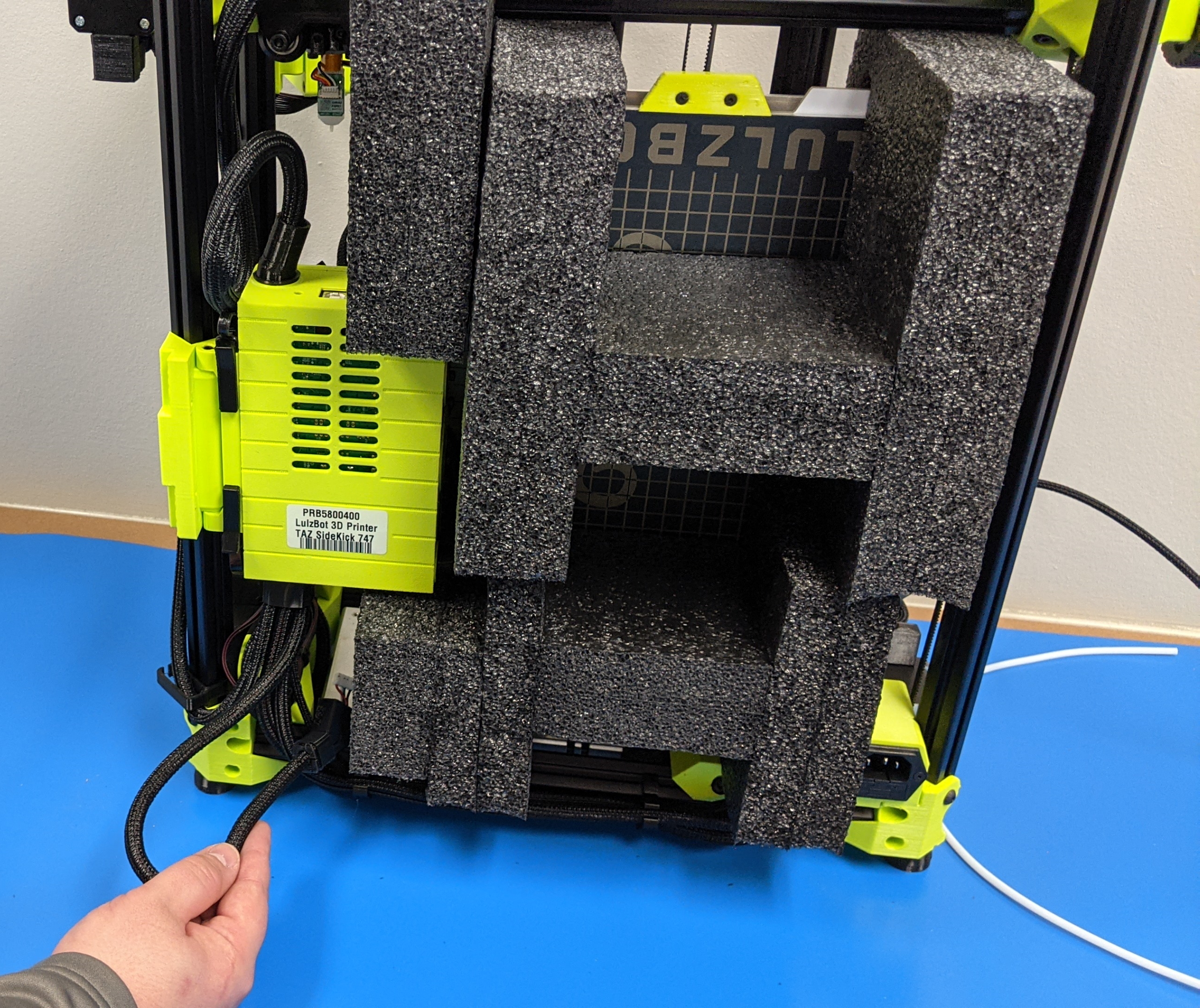
If your SideKick came with a runout sensor, it will need to be removed from the printer's frame.
4A
Untuck in cables and harnesses for the y-axis
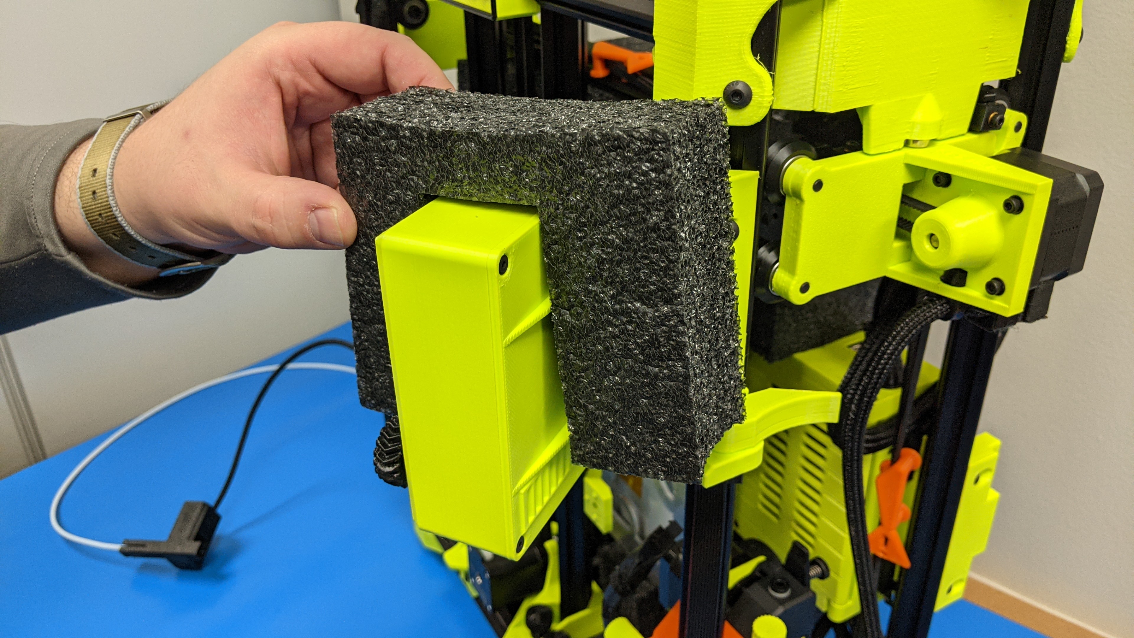
4B
Remove control box foam from above control box.
4C
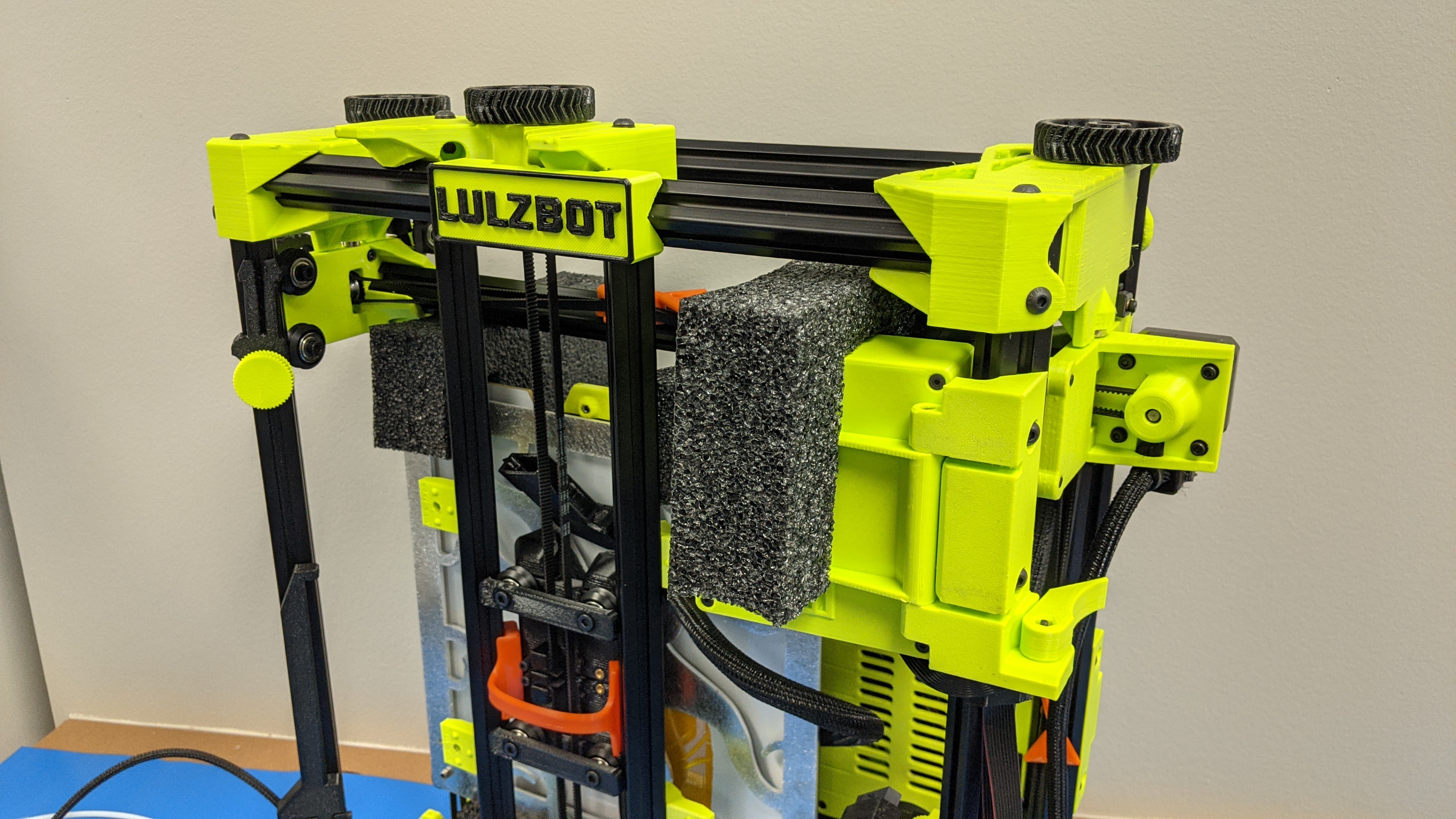
Rotate the LCD outwards from the printer frame.
Move the LCD support arm forward and remove the foam over the LCD.
4D
Gather LCD foam and control box foam and save for future use.
4E
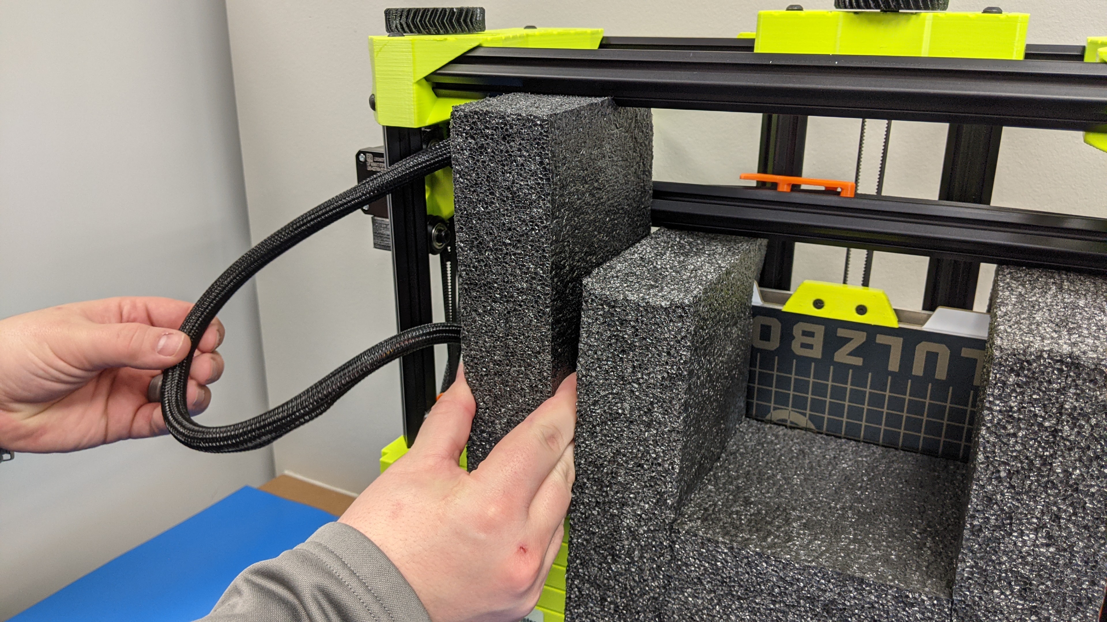
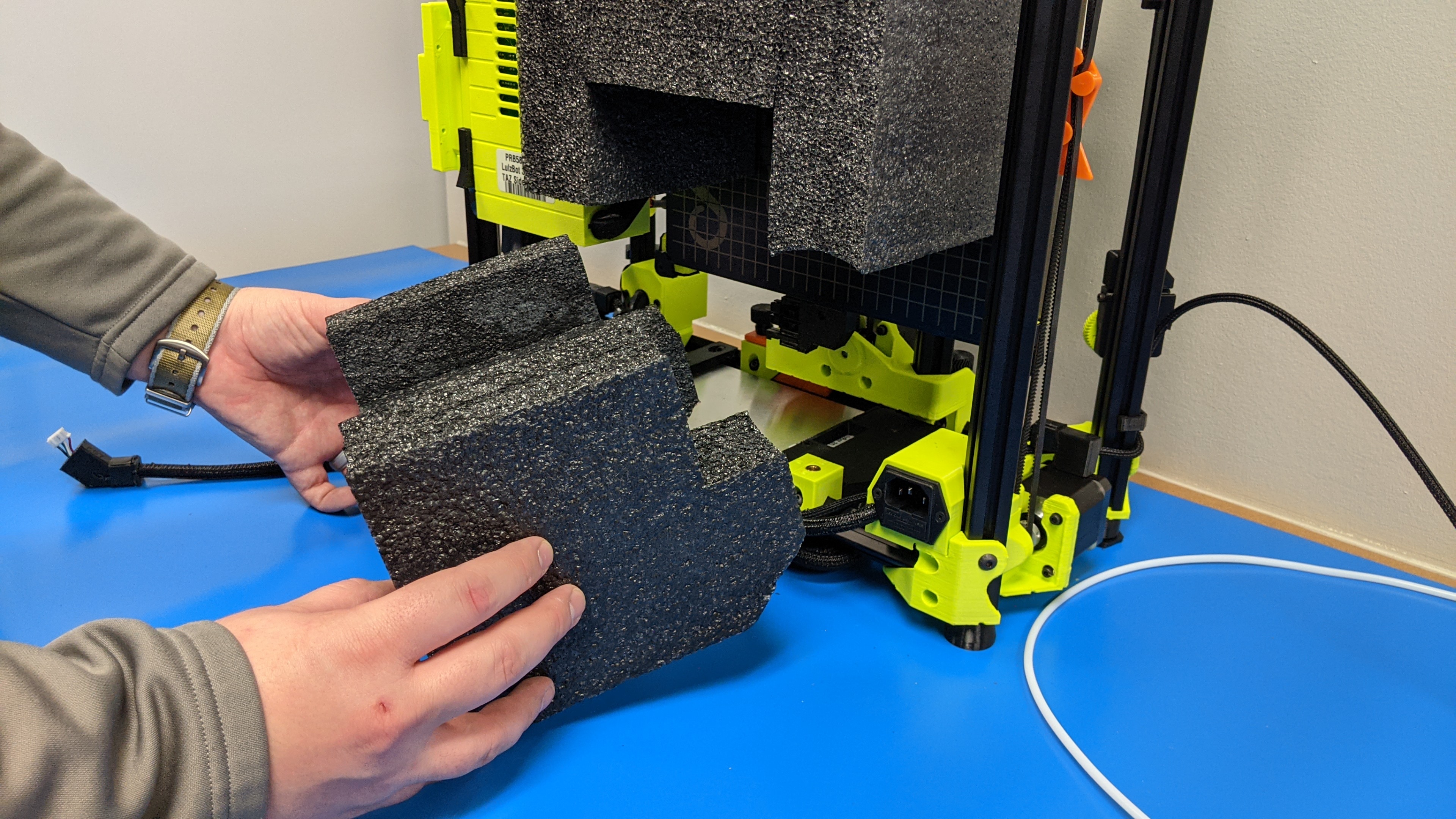
Slide the bottom foam piece out of position.
4F
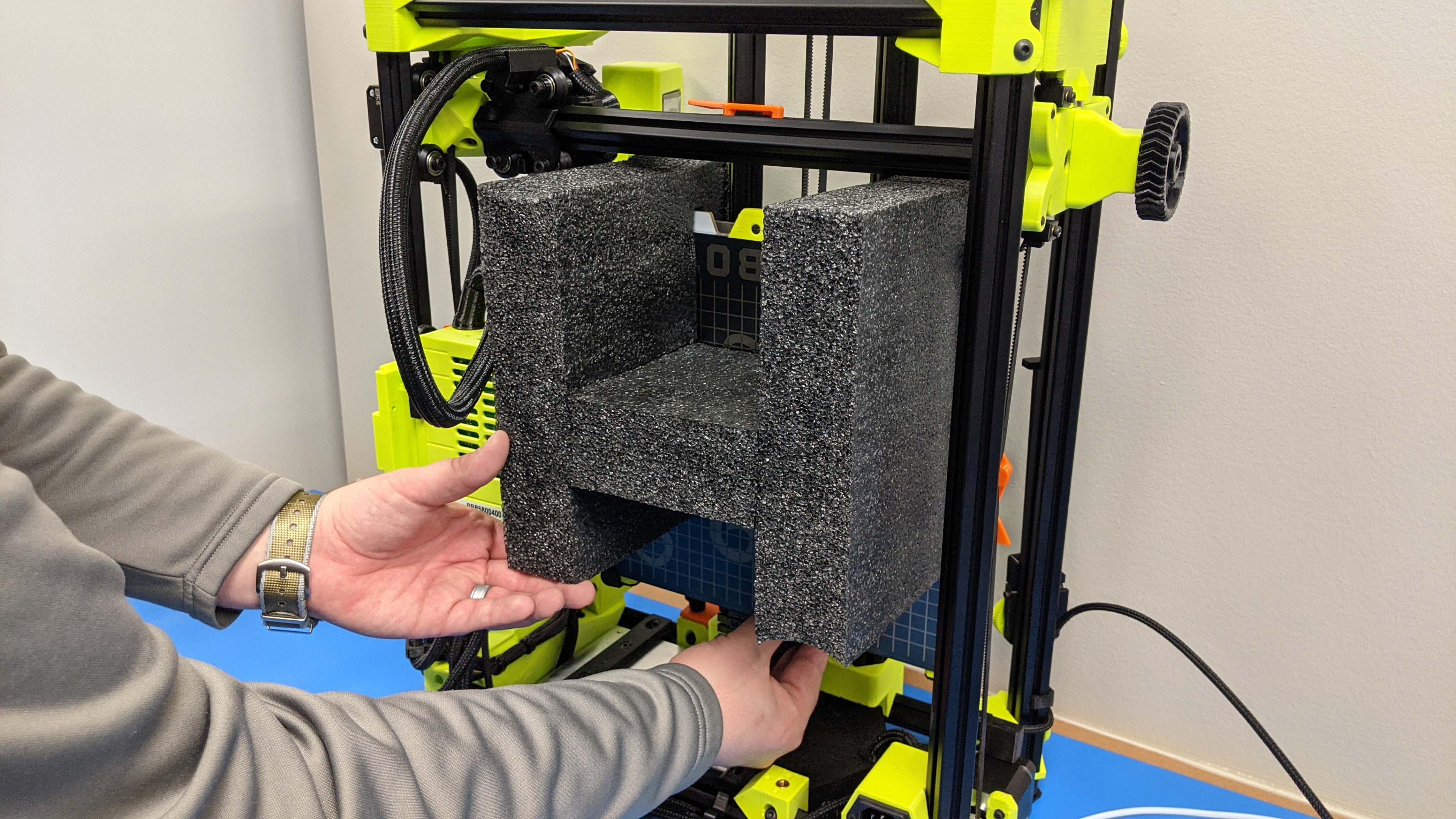
Lower the bed and remove the top y-axis foam from the print bed.
4G
Gather internal y-axis foam and save.
4H
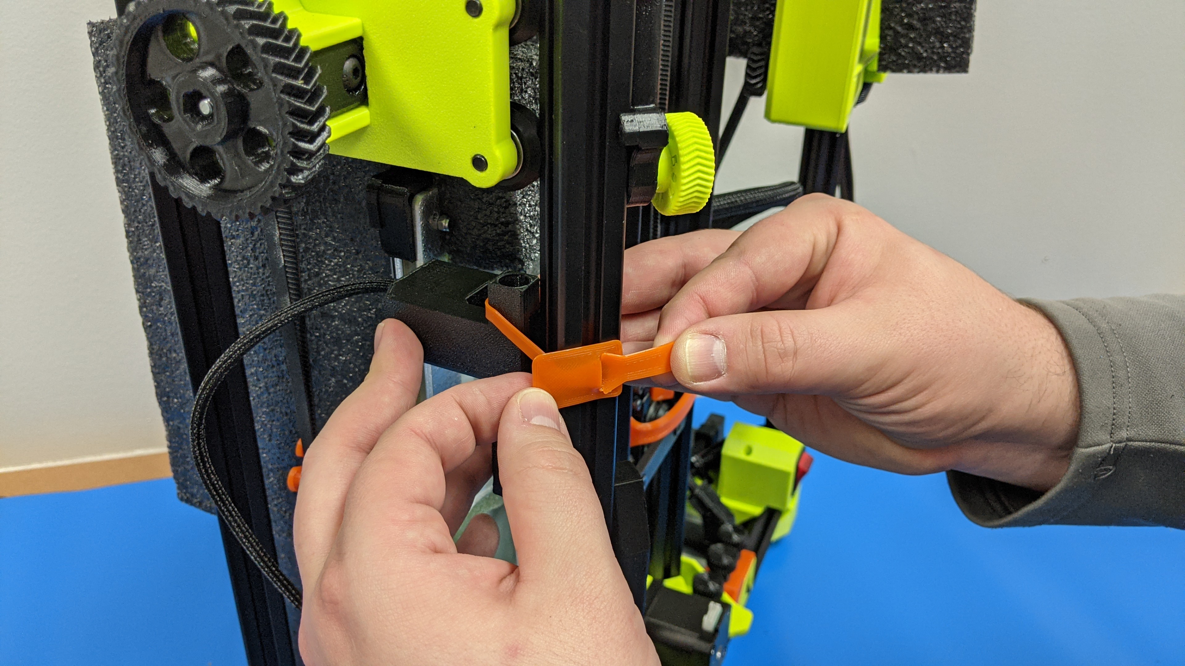
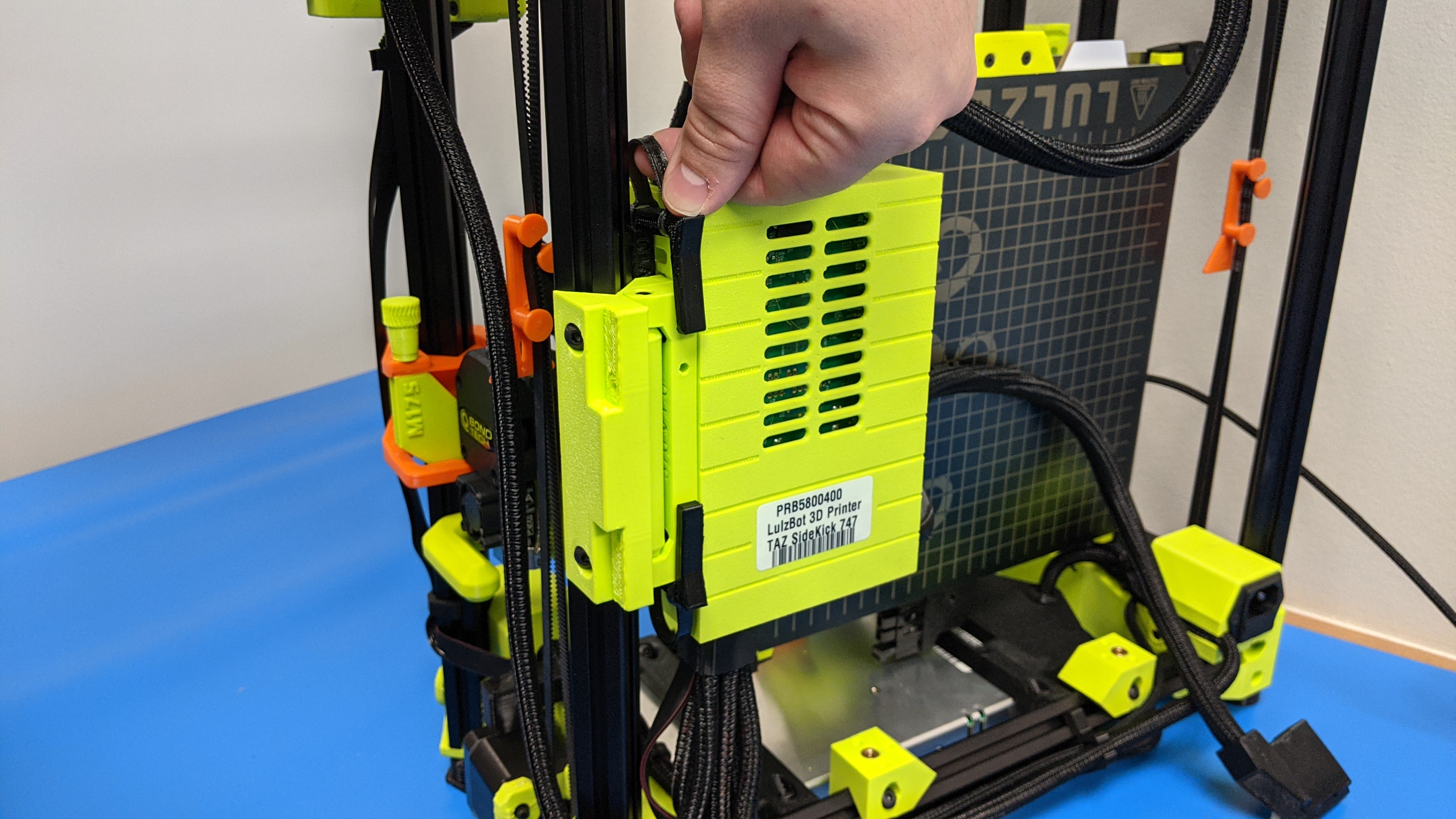
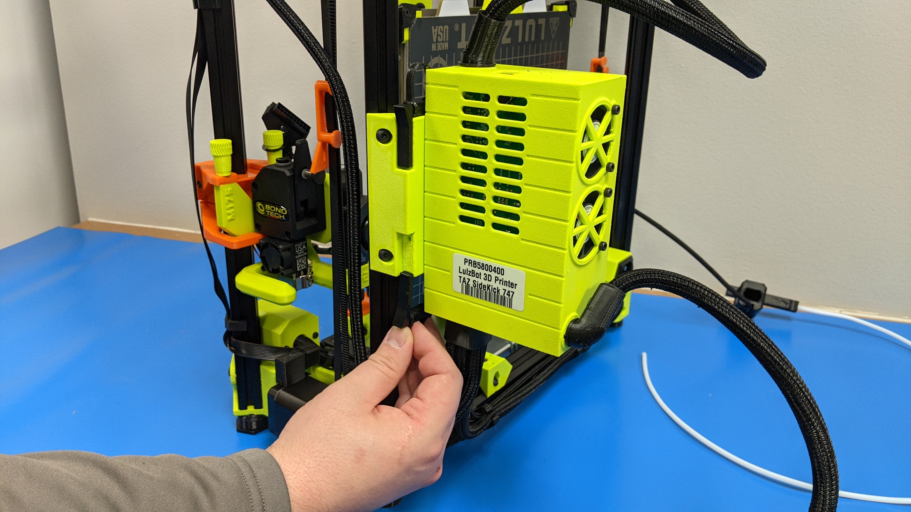
Remove the two clips holding the control box in position.
Flip the box outwards and secure with the same clips.
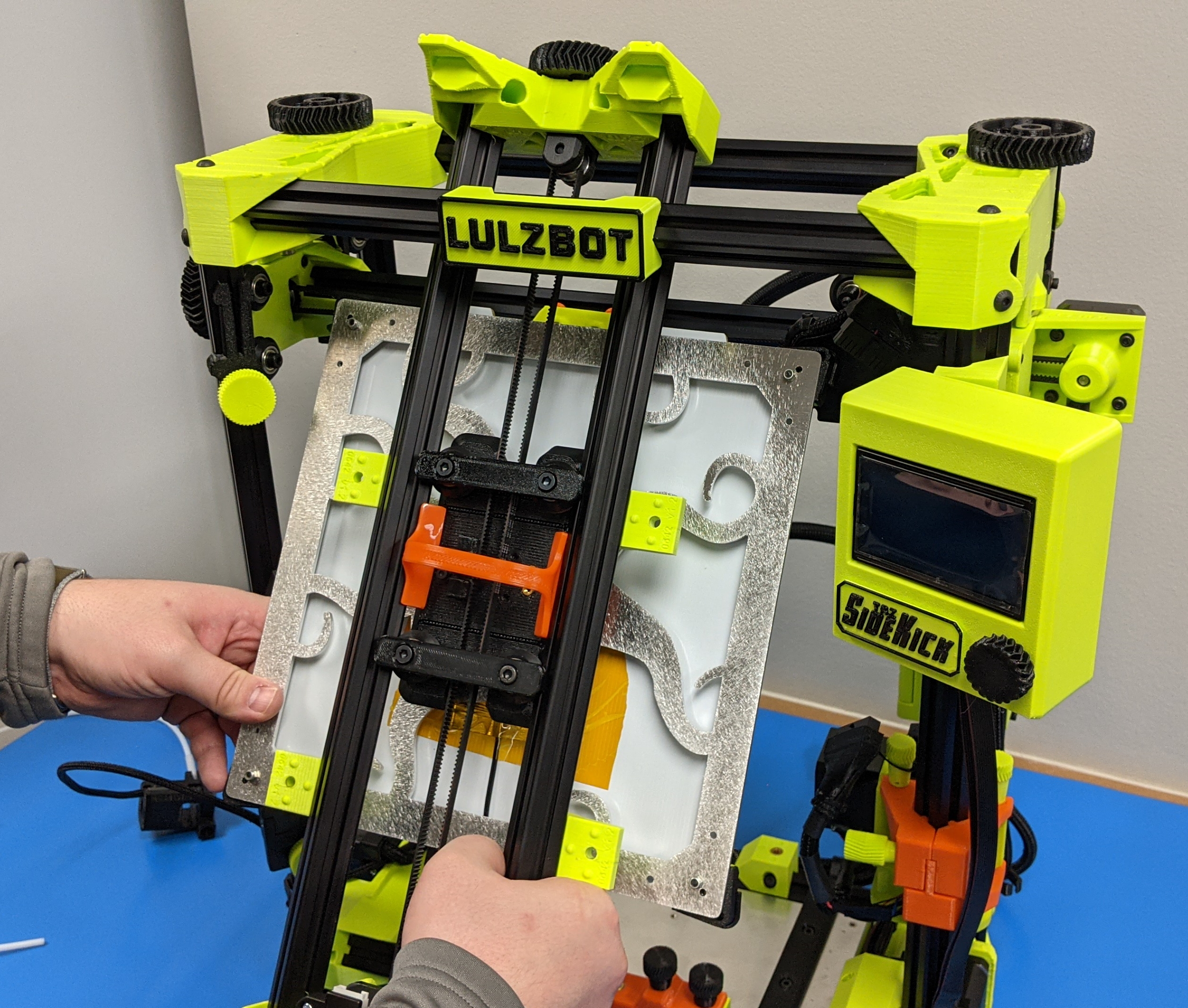
The y-axis bed will need to be removed before mounting the y-axis inside the printers frame.
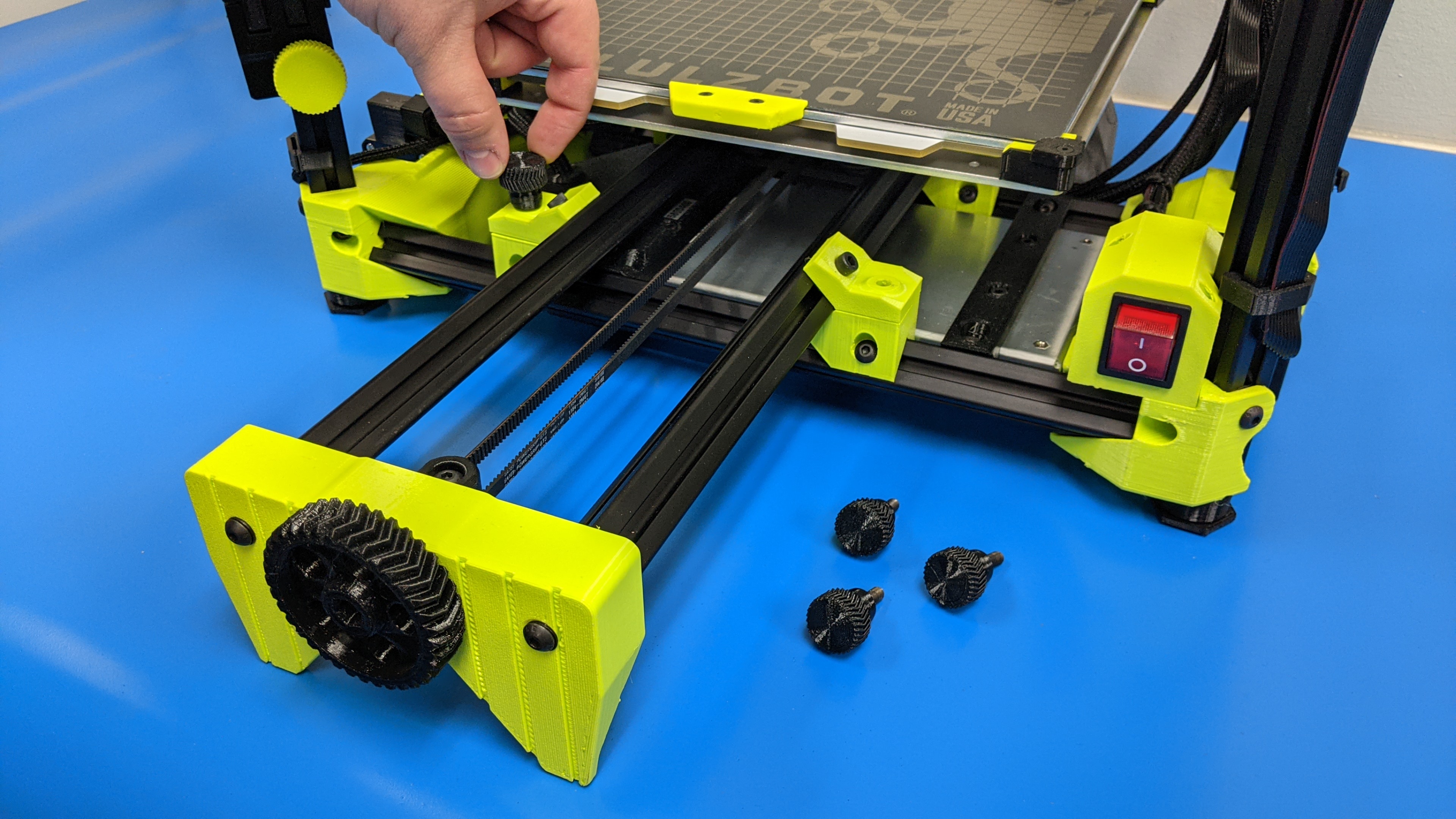
5A
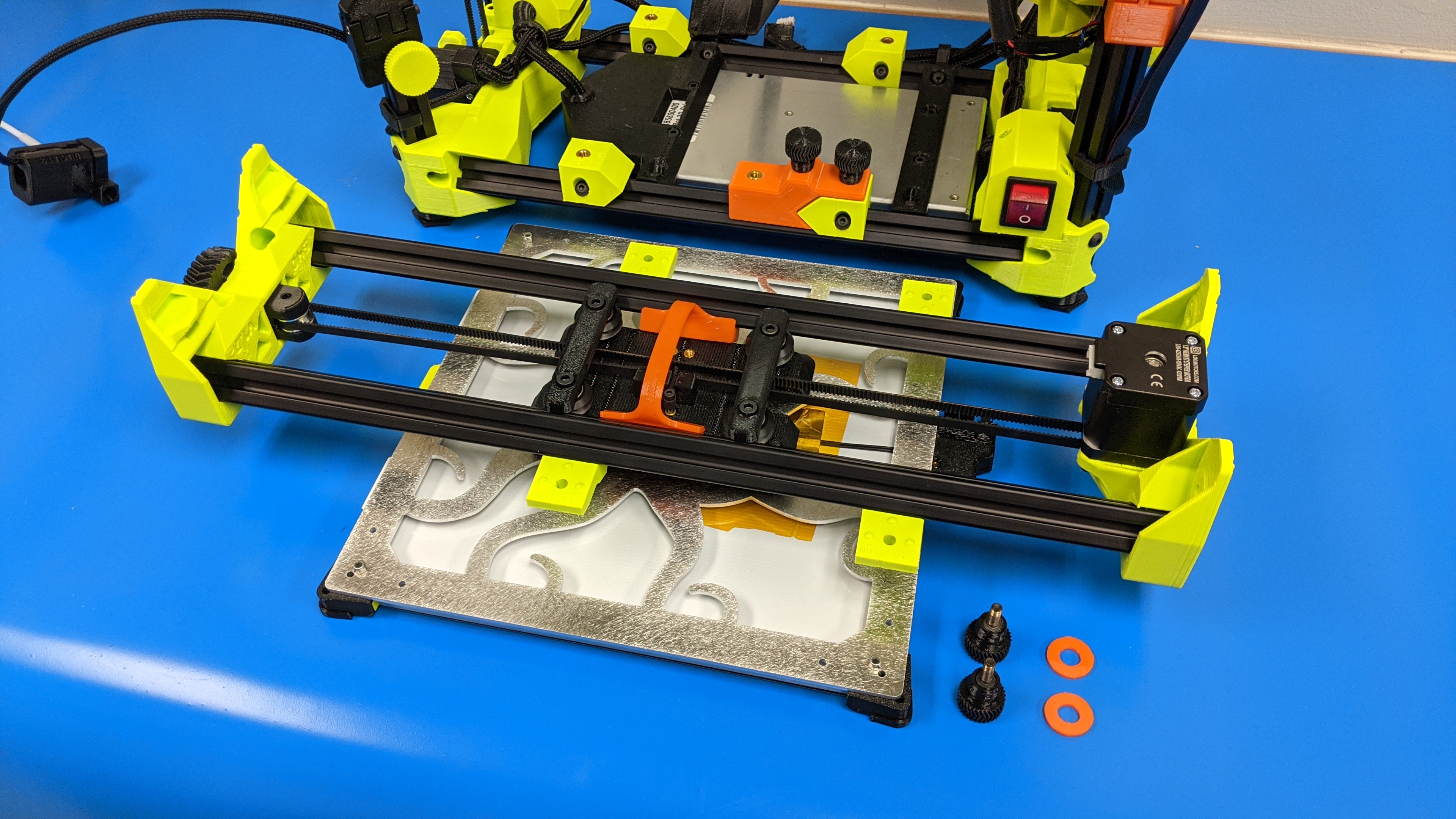
Unsecure the y-axis to the printer frame using the two thumb screws.
Remove the two O-rings on the bottom two open inserts and set aside
5B
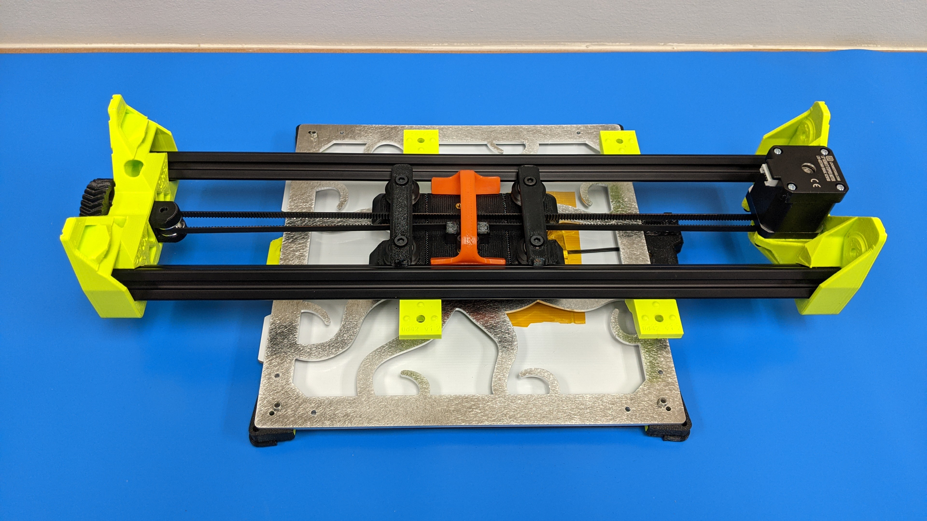
Slide the idler side of the y-axis out of the printer's frame between the front extrusion and the x-axis rail.
5C
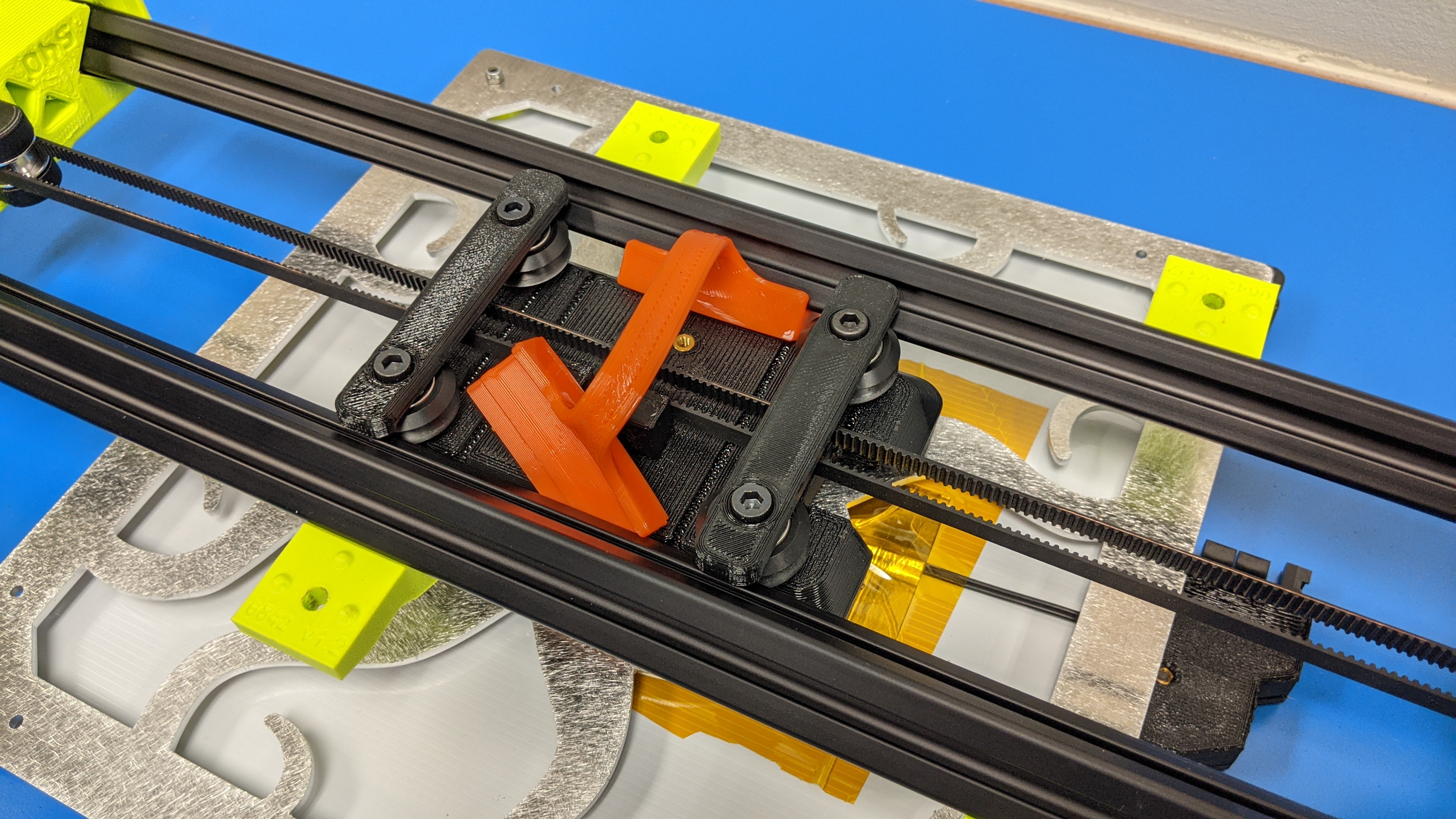
Remove the flexible wedge from the y-axis between the bearings.
5D
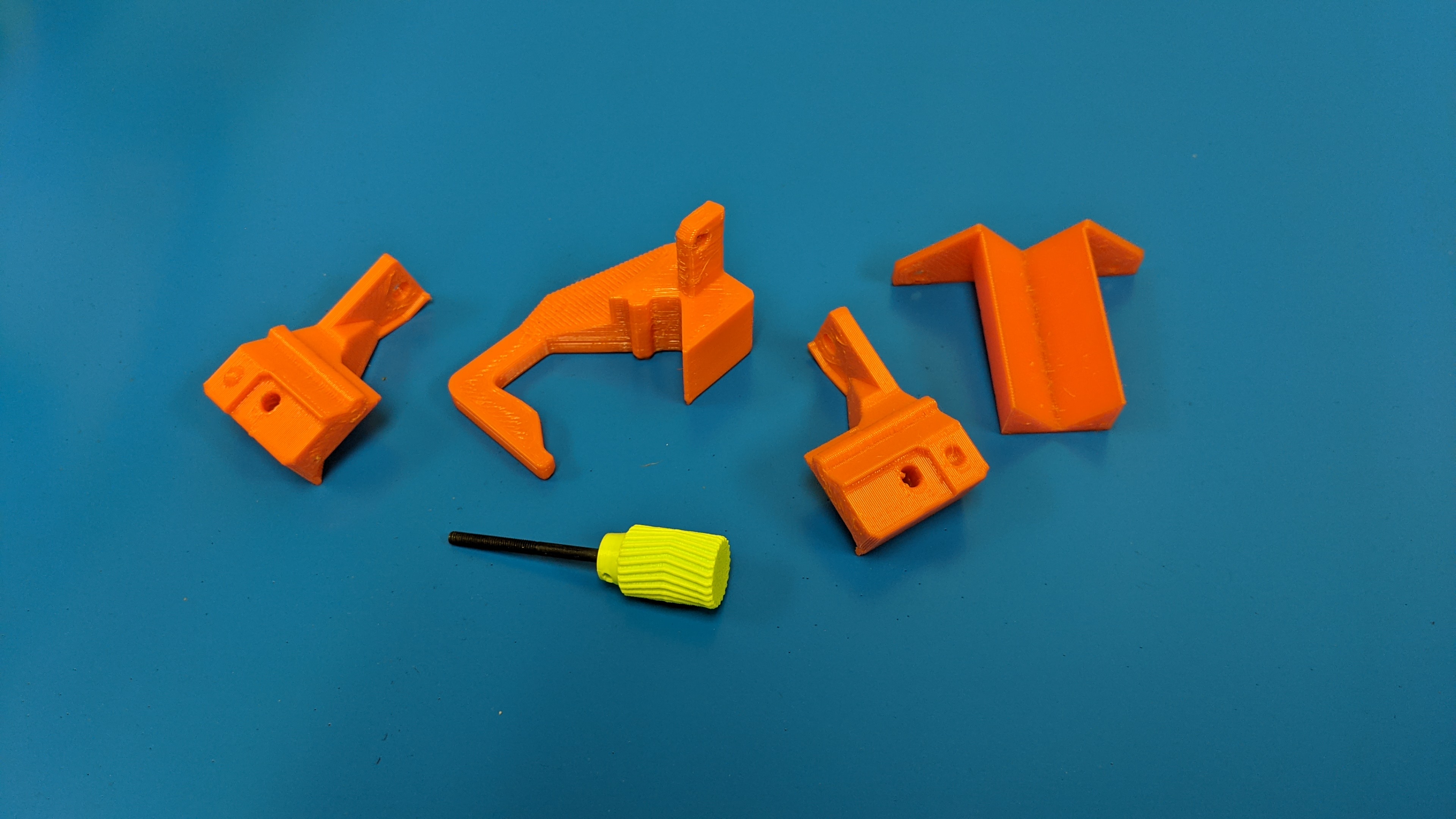
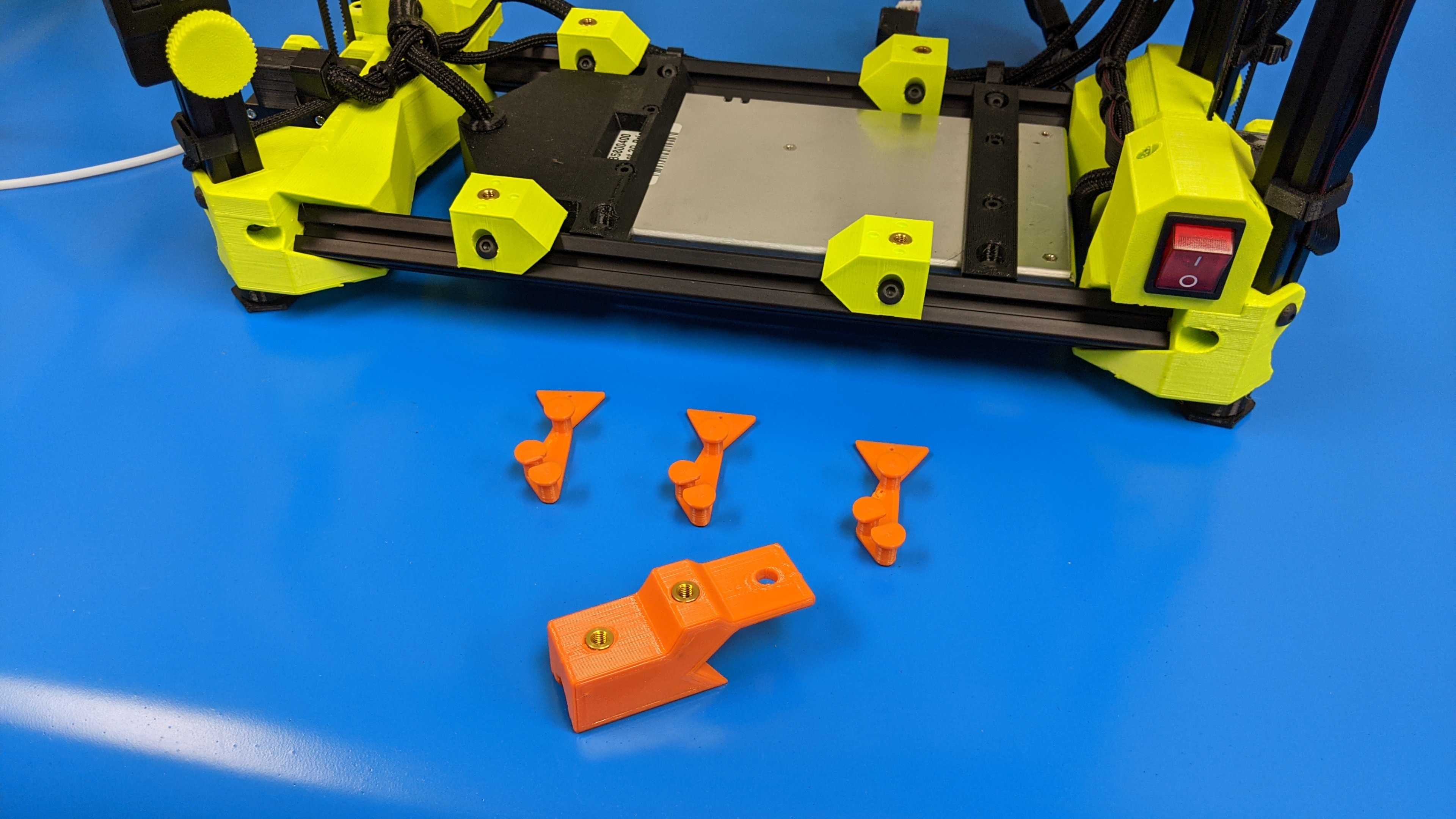
Save all orange hardware for future use.
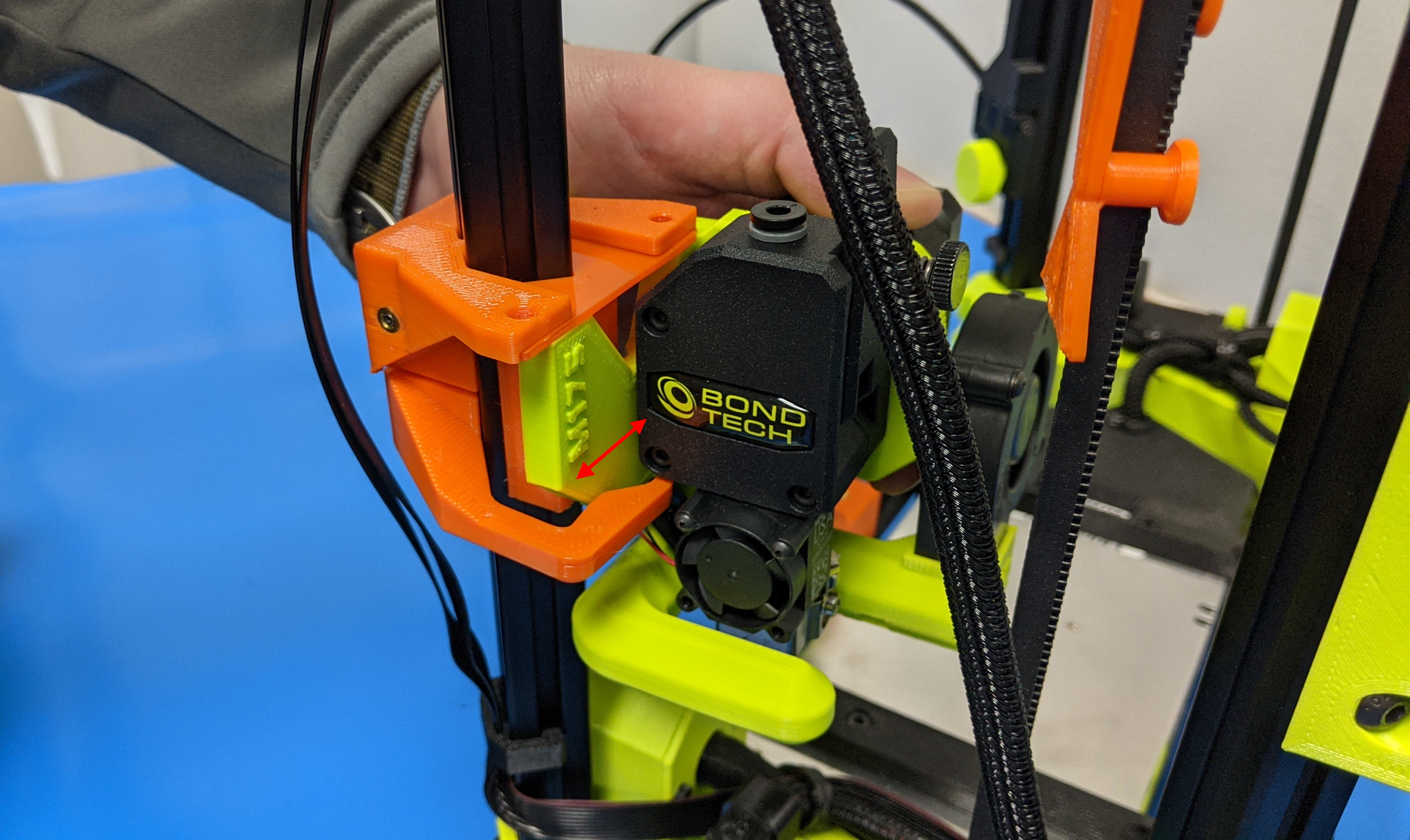
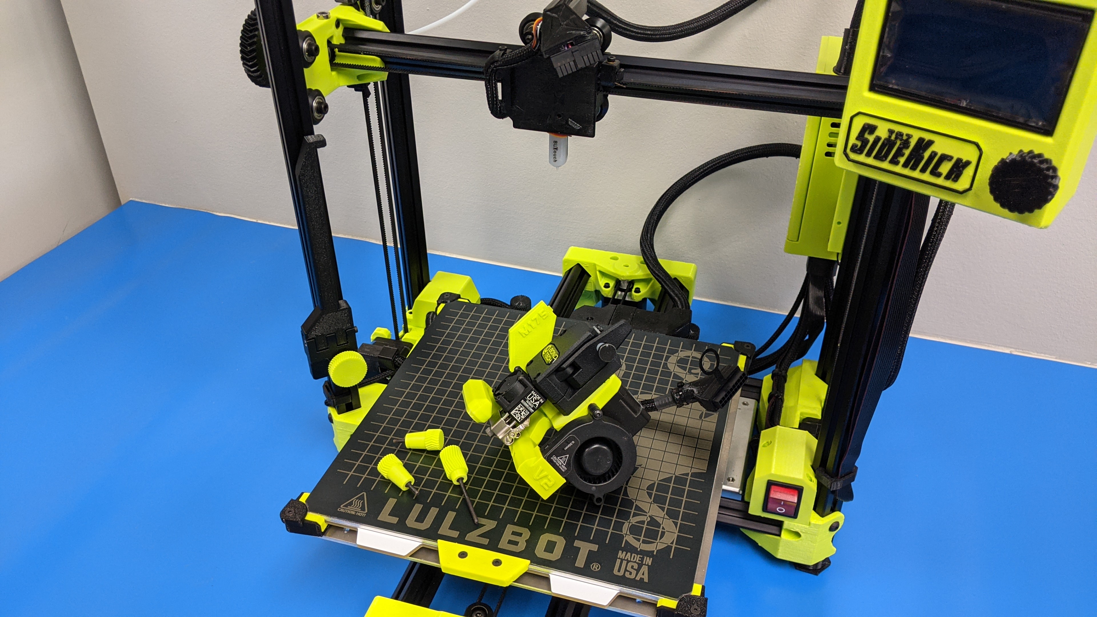
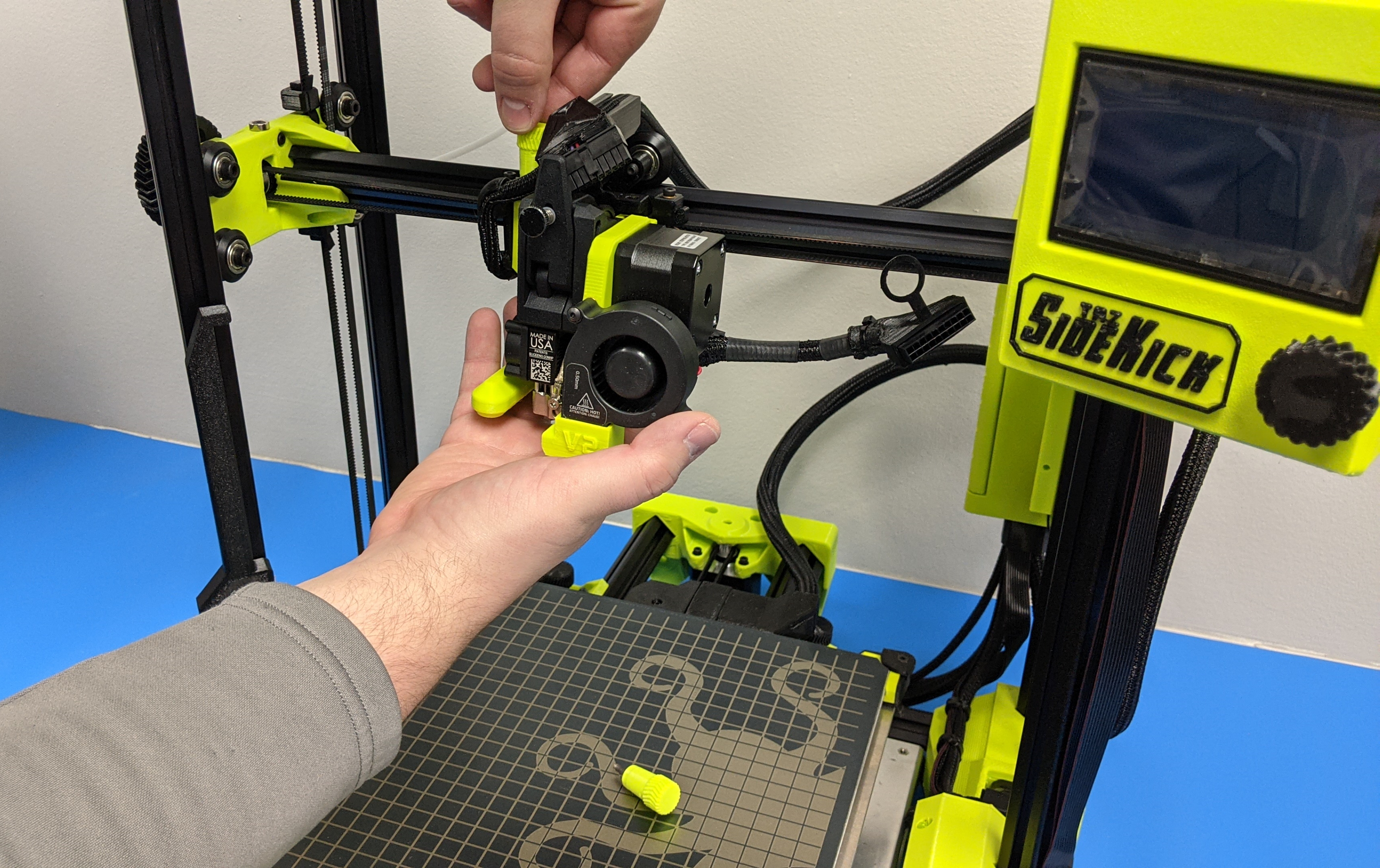
6A Unsecure the tool head to the mount by removing the two tool head mount screws.
6B
Slide tool head out of position from the mount.
6C
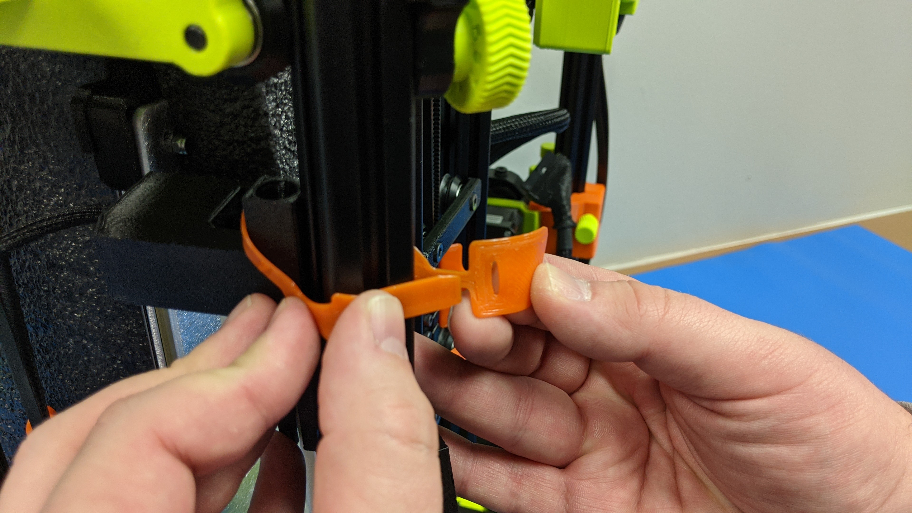
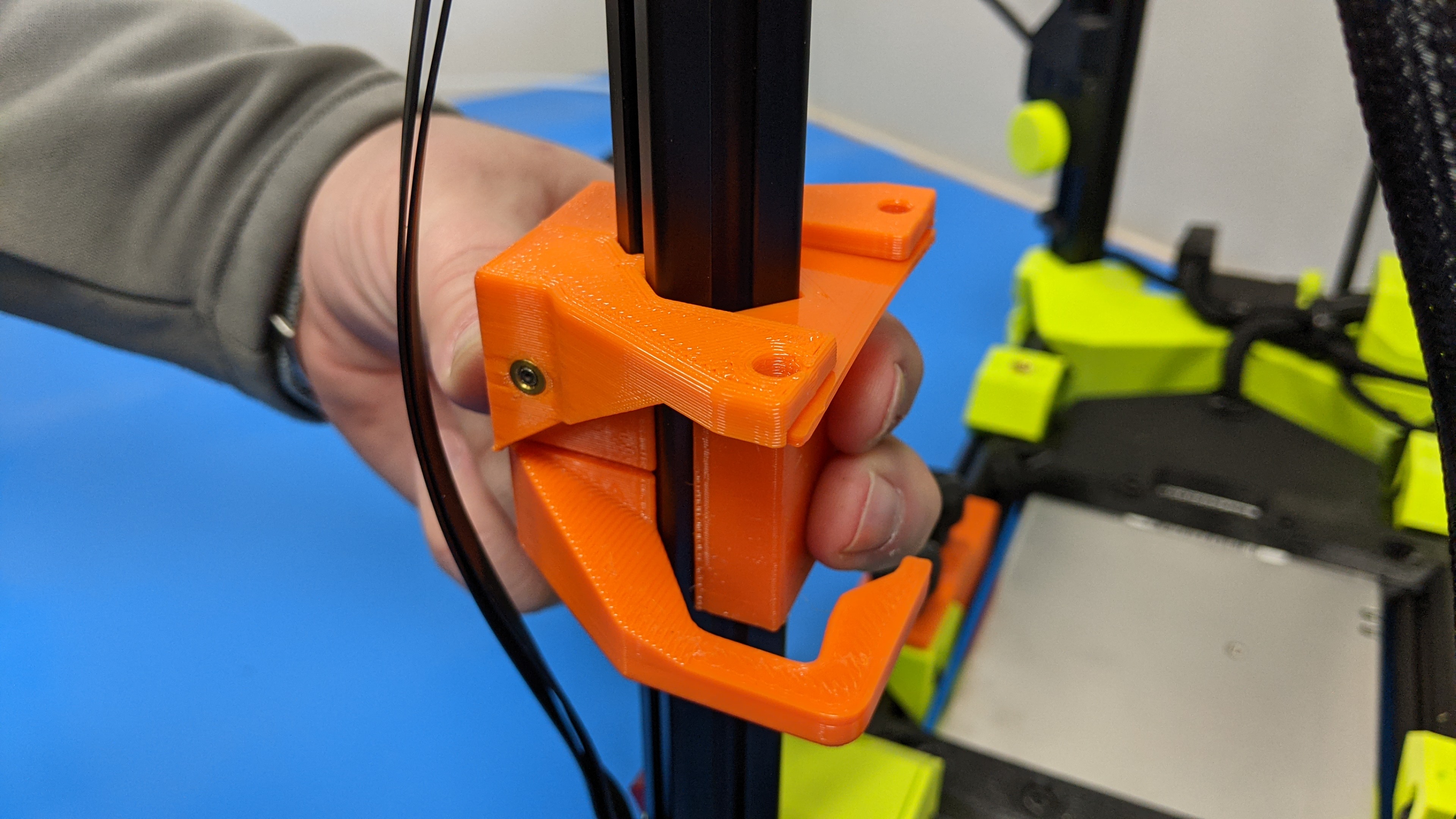
Remove flexible orange mount on other side of the tool head mount.
6D
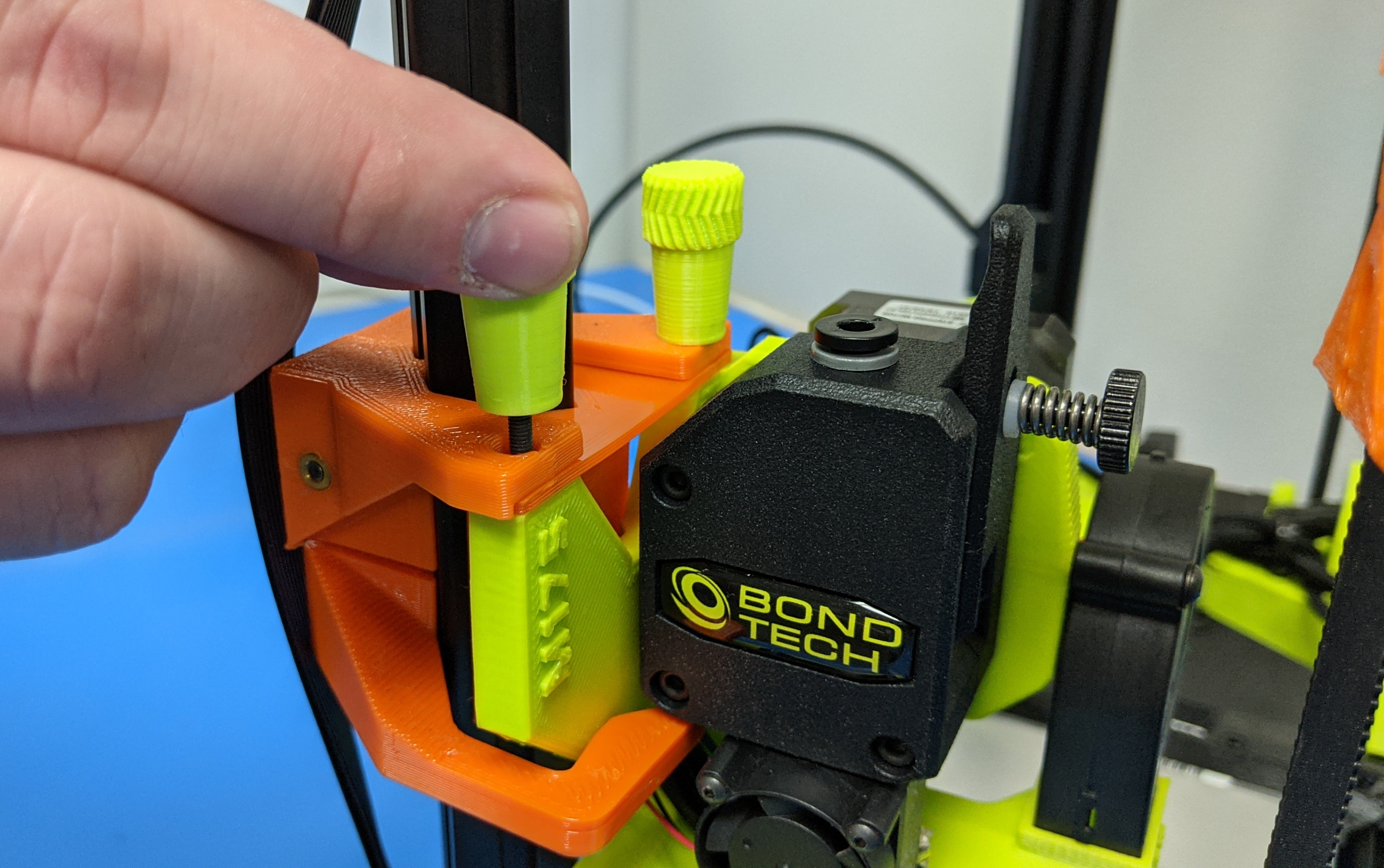
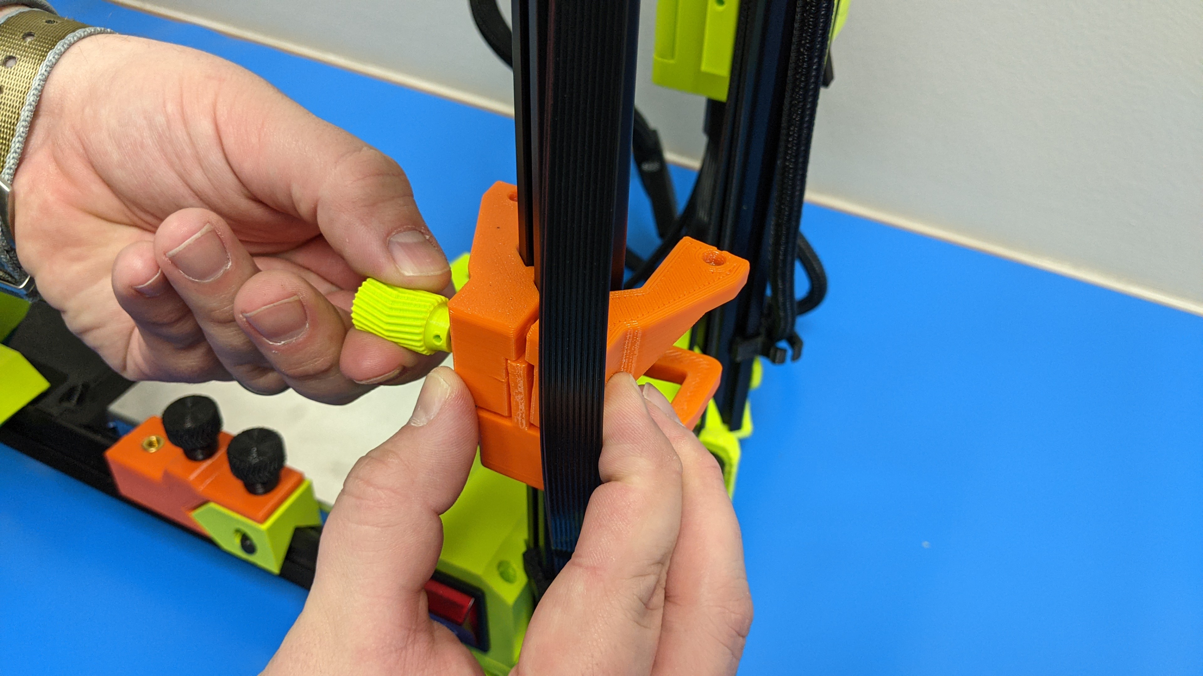
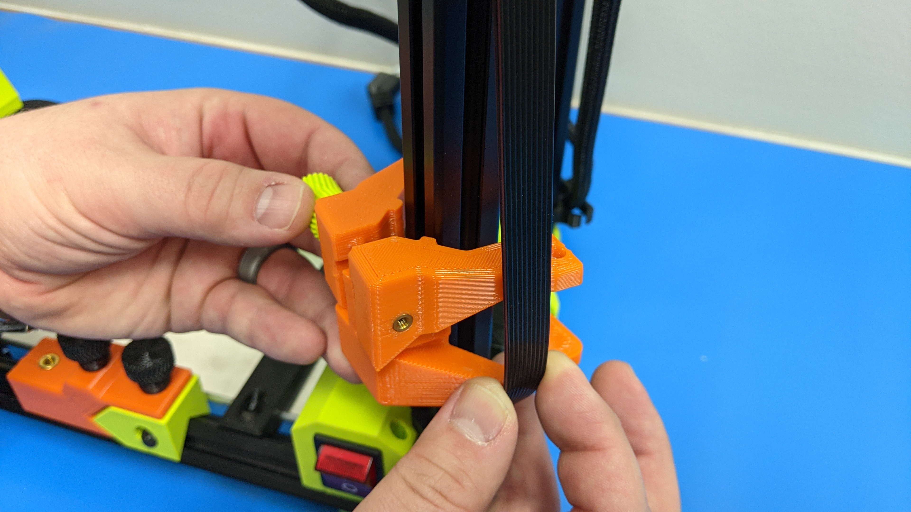
Loosen the thumb screw on the side of the orange tool head mount to loosen it.
Remove the mount from the extrusion.
6E
Remove the thumb screw completely and set aside.
Save all orange hardware for future use.
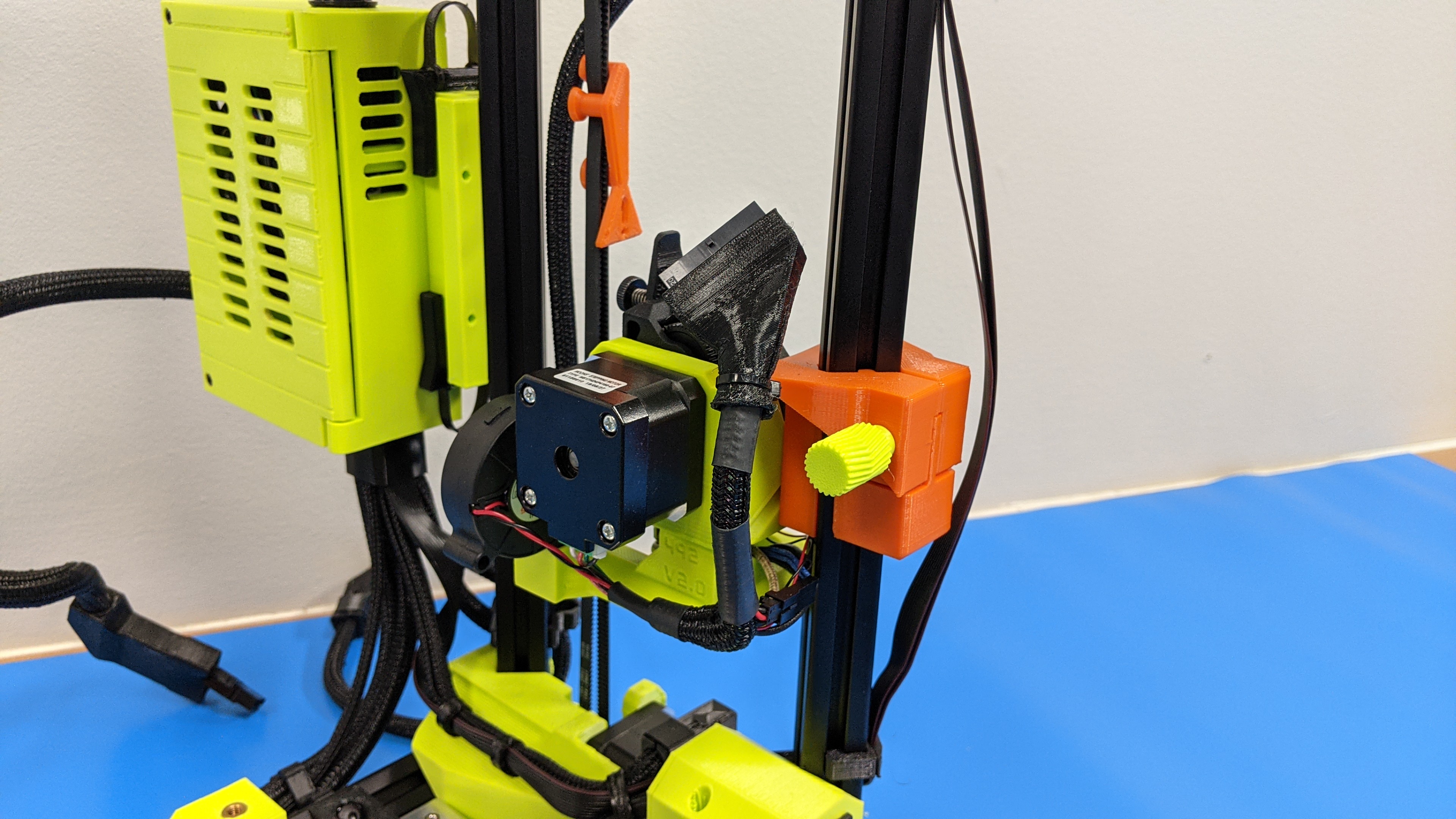
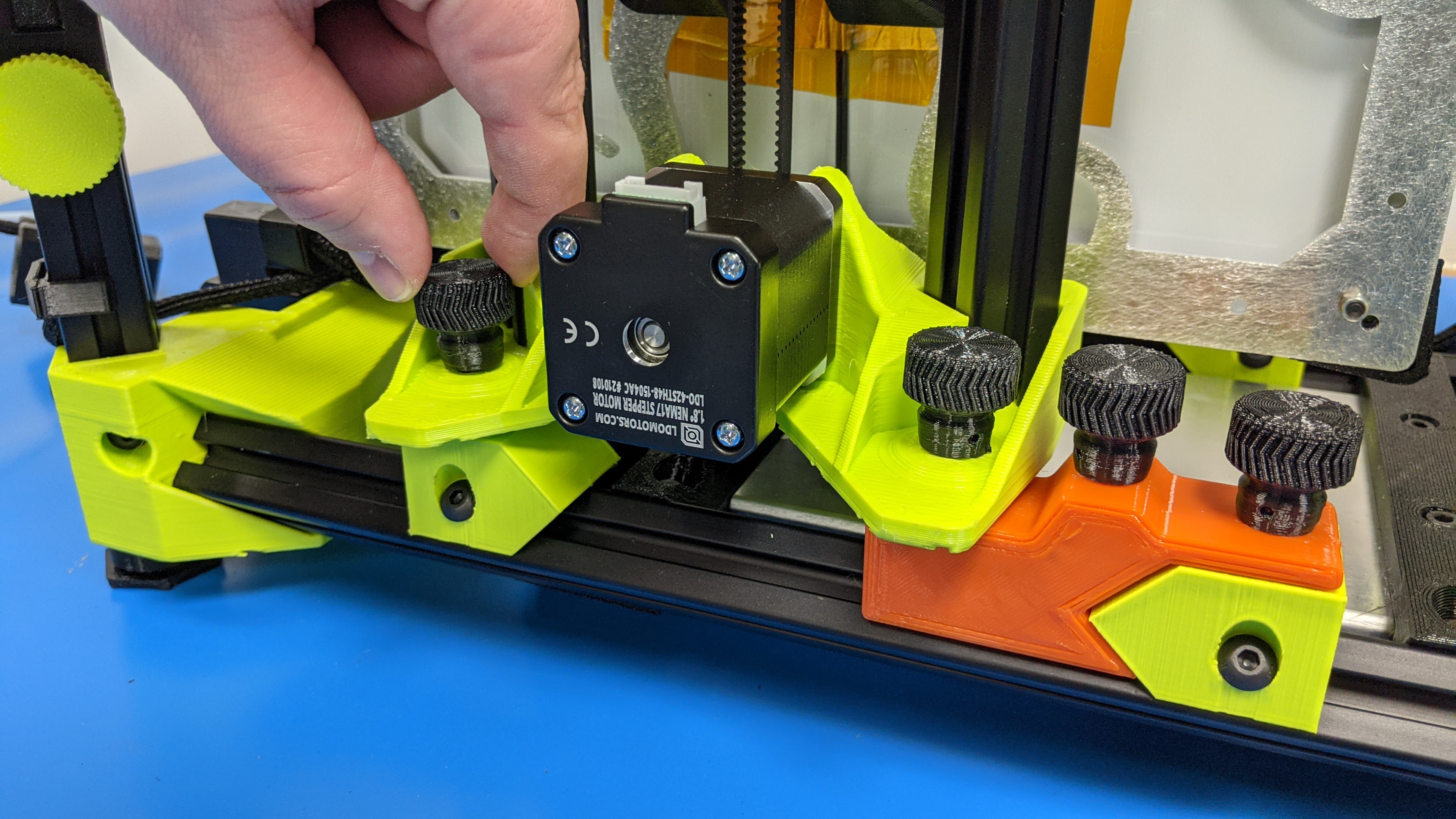
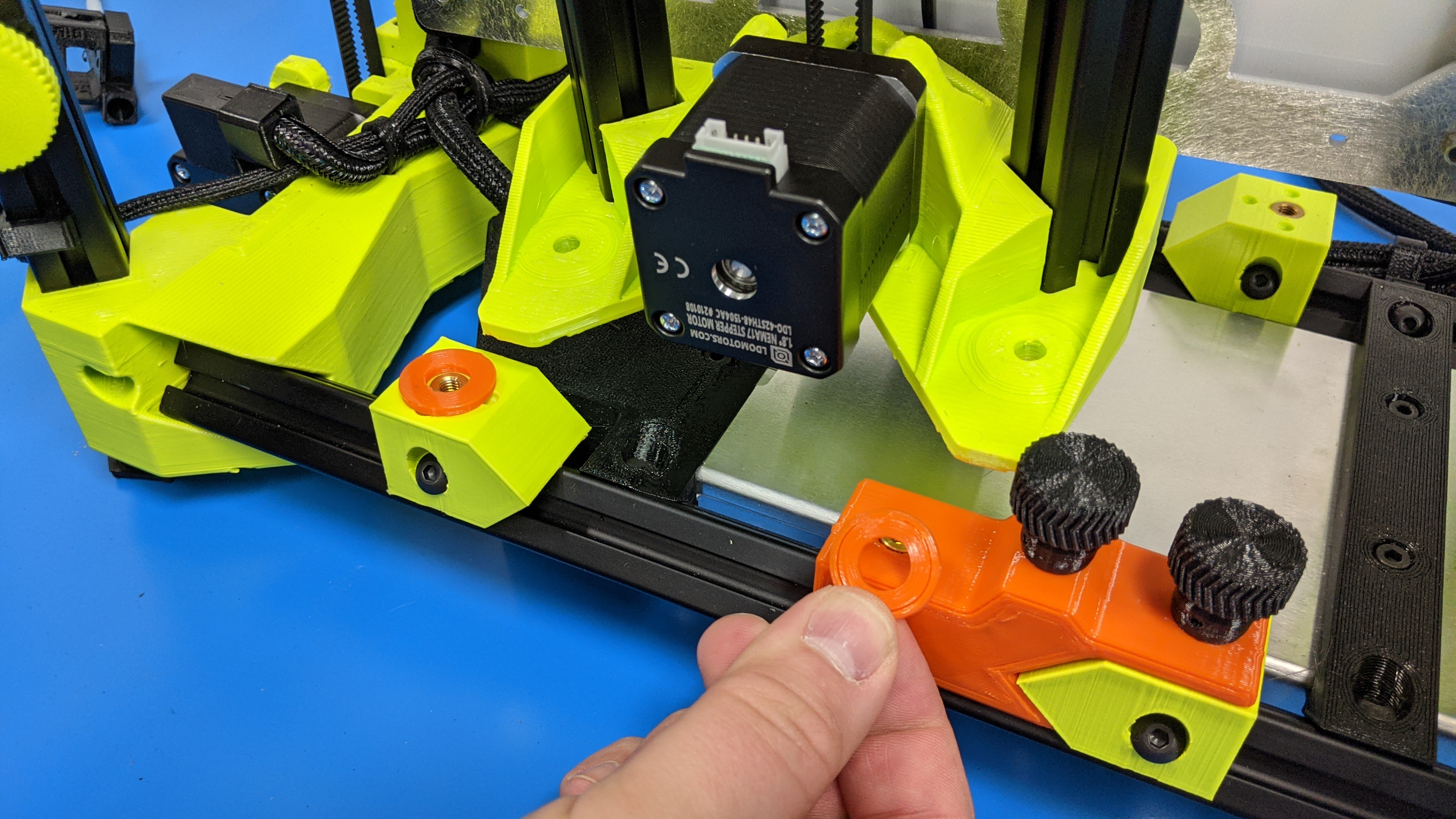
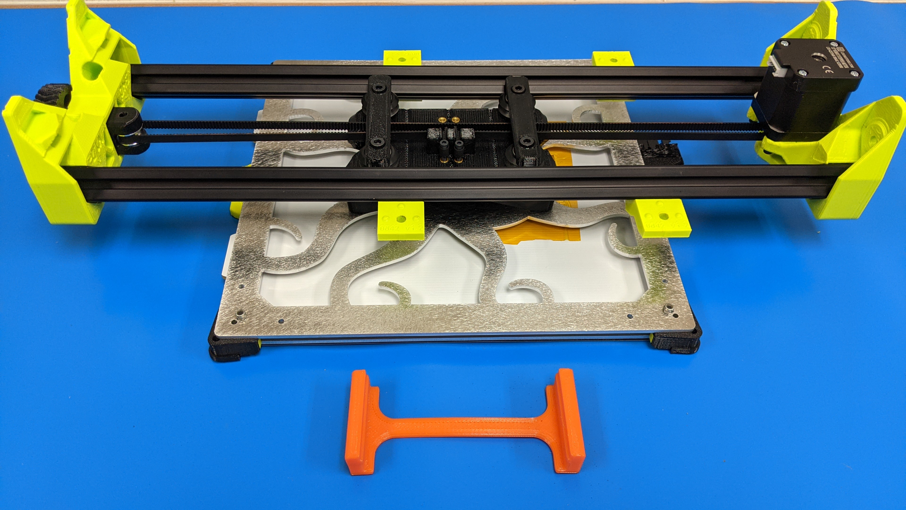
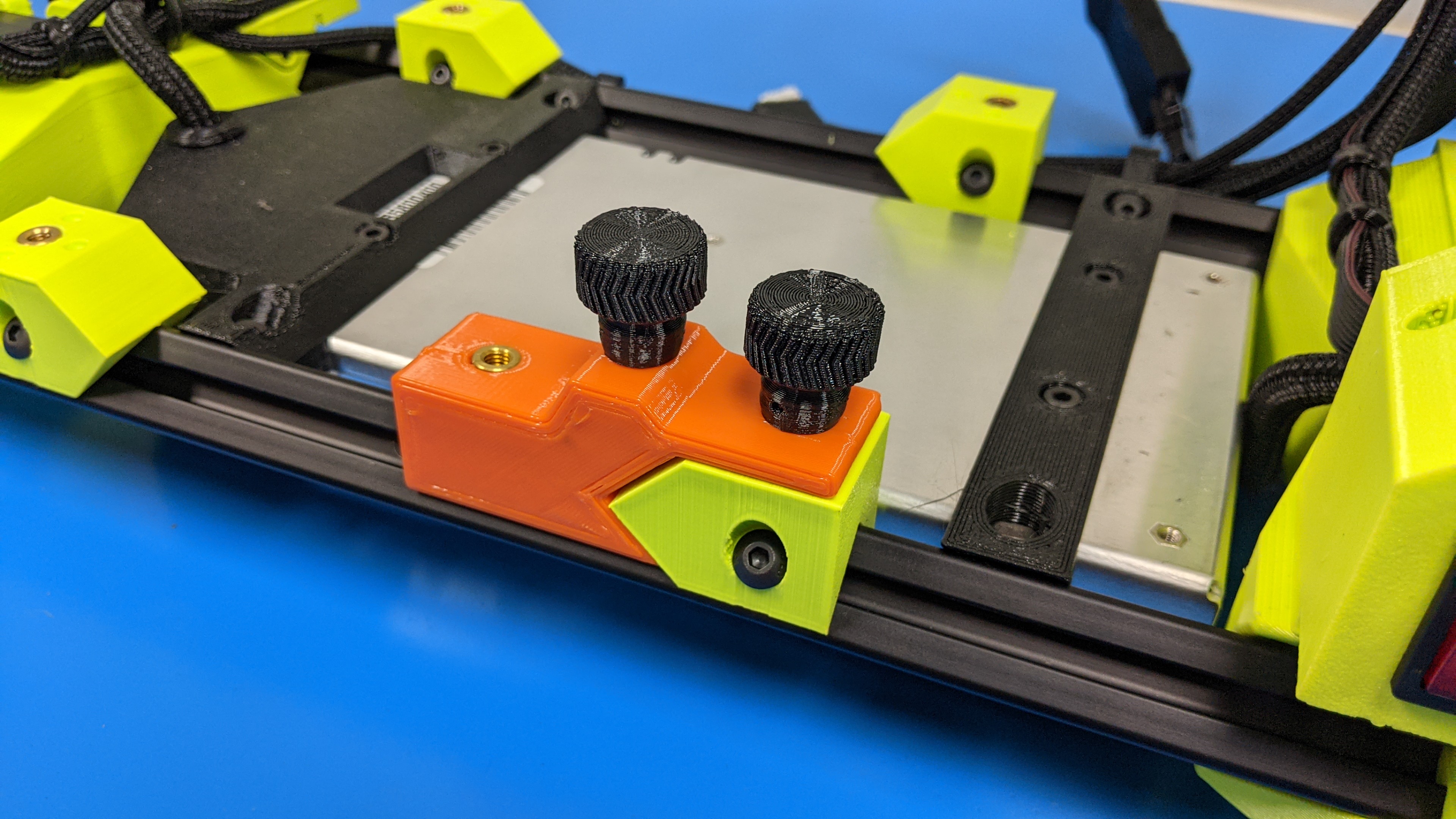
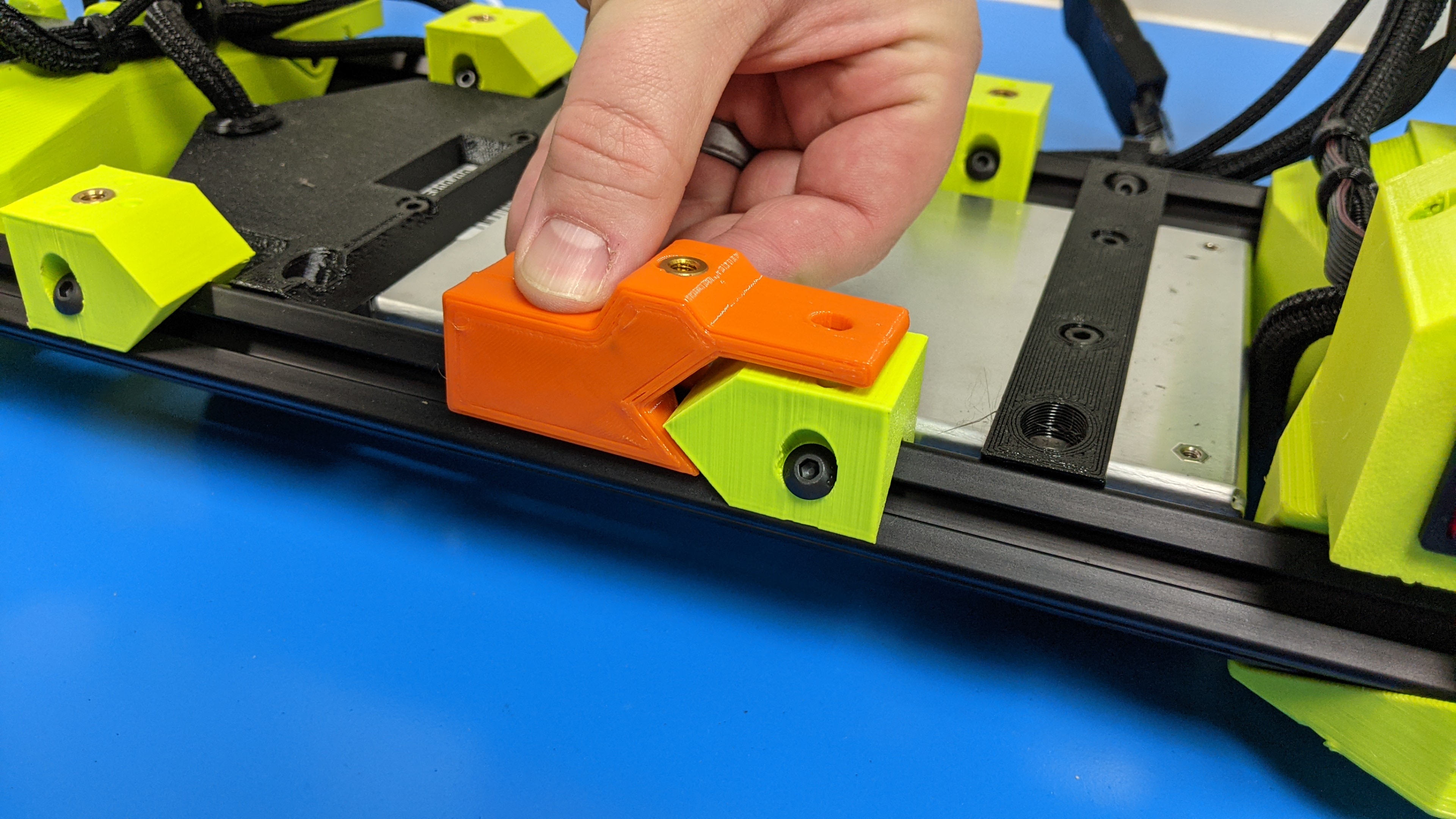
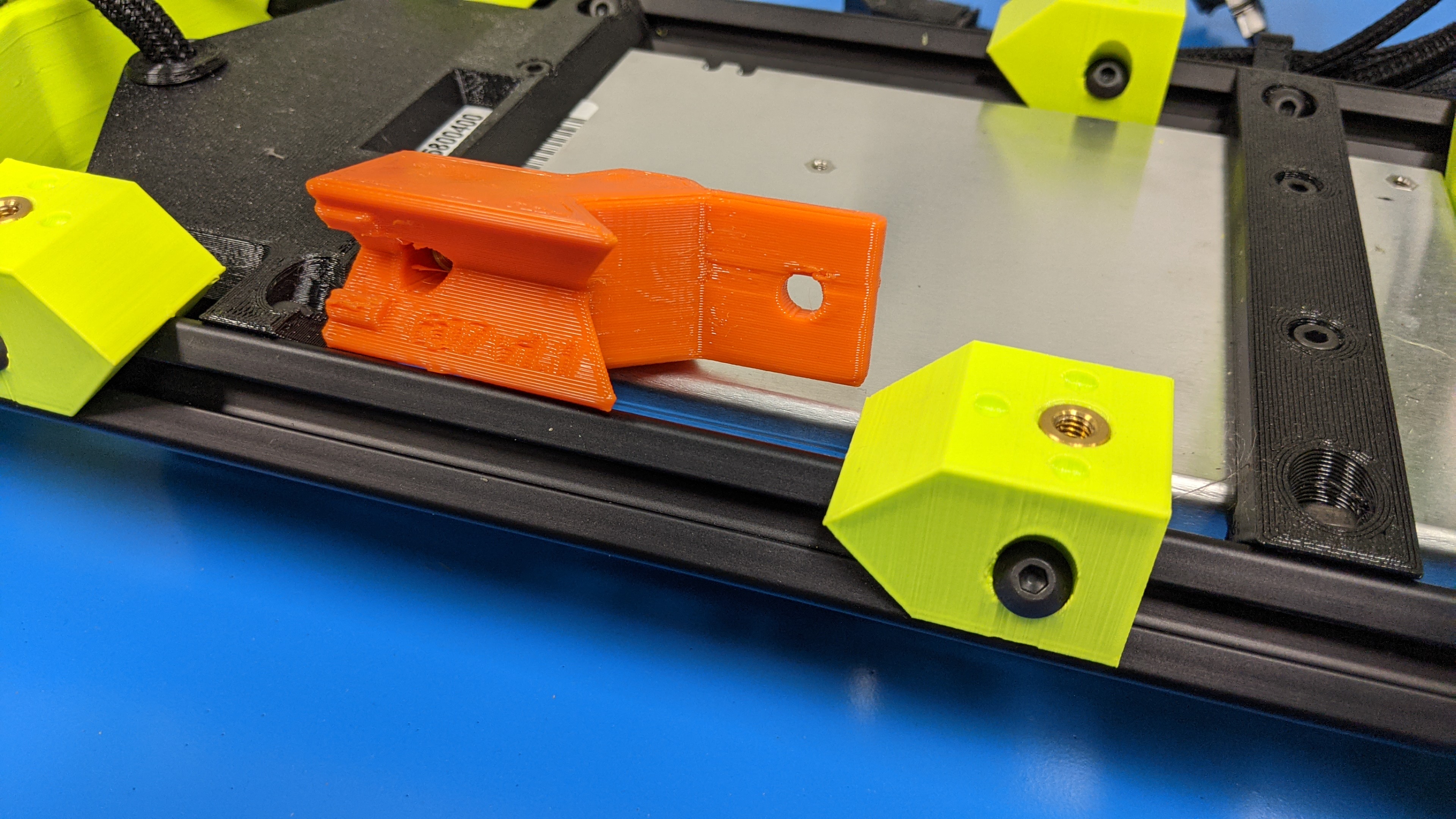
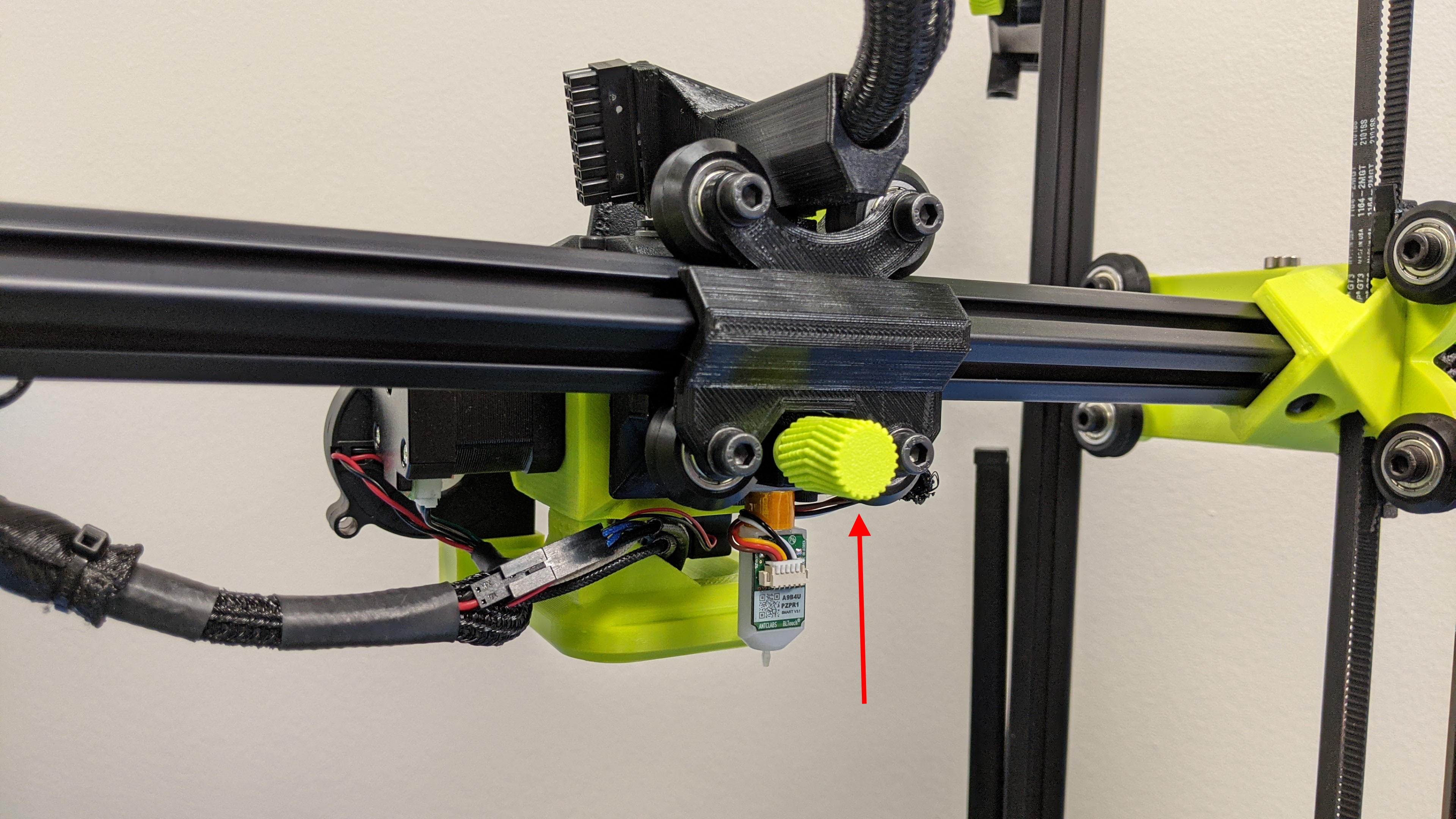
7A
Remove the two y-axis thumb screws that hold the orange mount piece in place
Remove the orange y-axis bed mount and place it to the side.
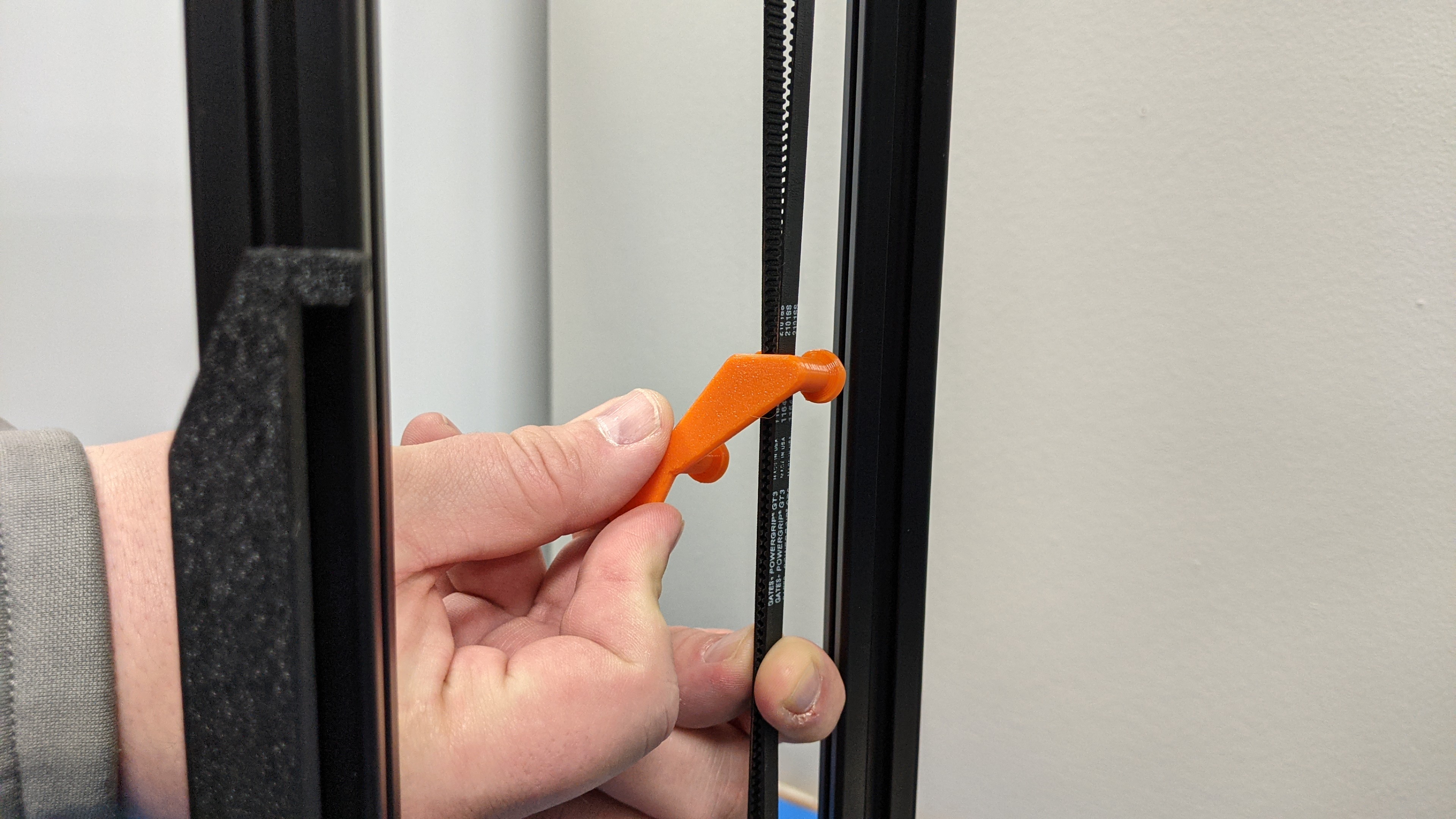
7B
Remove all 3 belt clamps by rotating the belt clamp and sliding the clamp off of the belts.
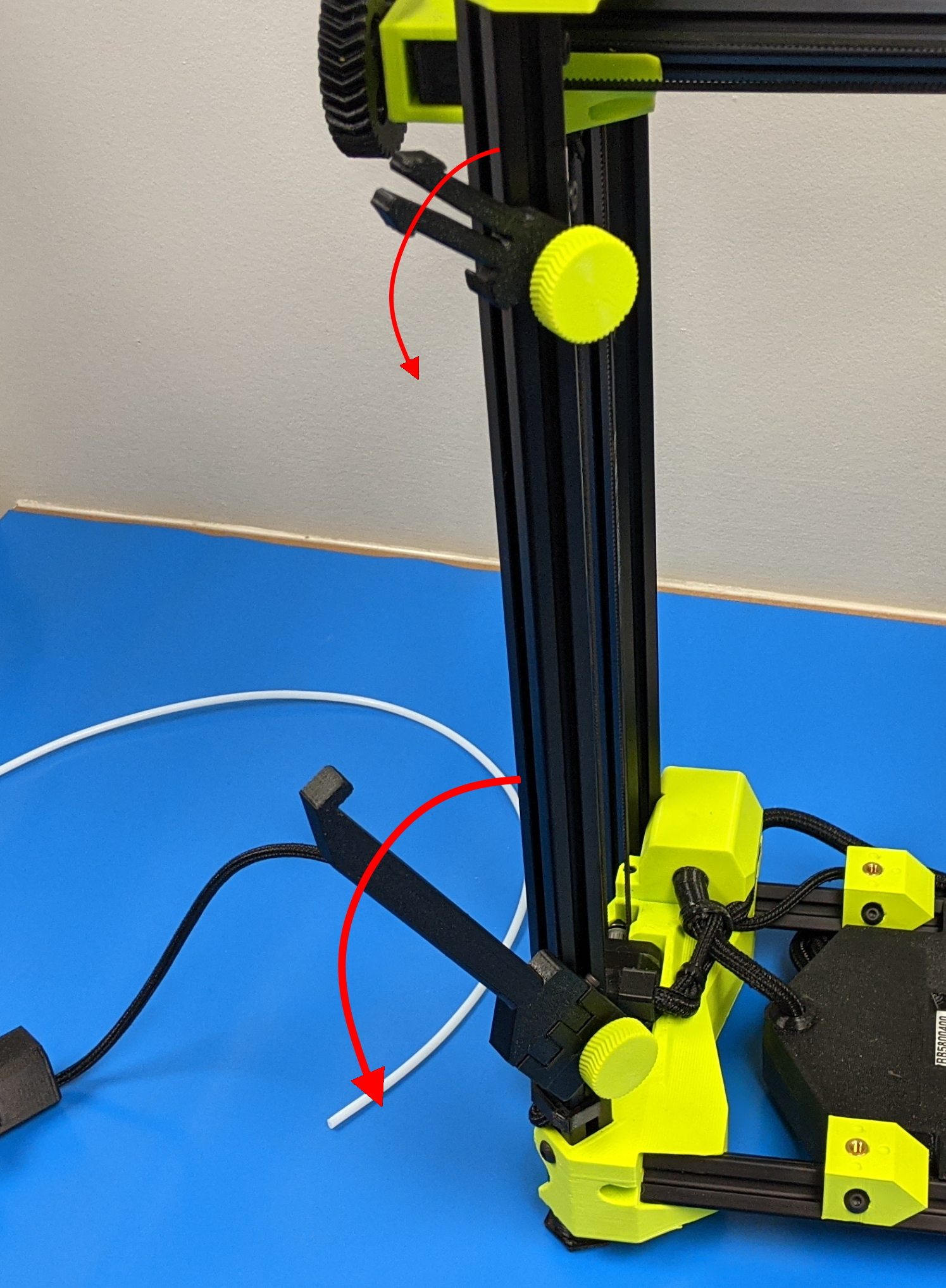
If your printer came with a runout sensor, this will need to be installed.
Loosen the thumb screws for the spool arm and guide tube mount and rotate them into their down and deployed position.
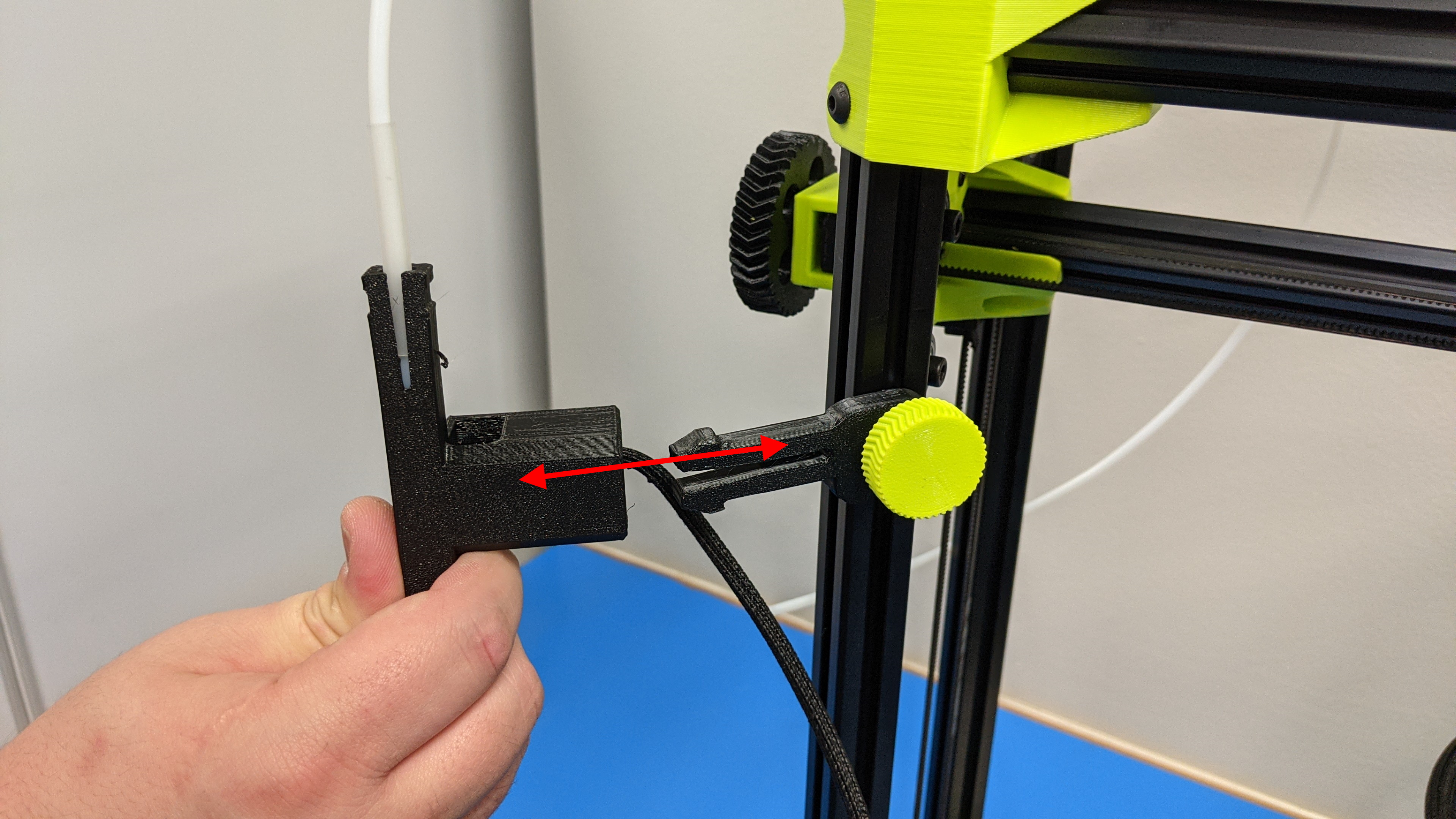
Push the runout sensor into the upper guide tube mount, noting orientation.
9A
Install the (4x) y-axis thumb screws to secure the y-axis to the printer frame.
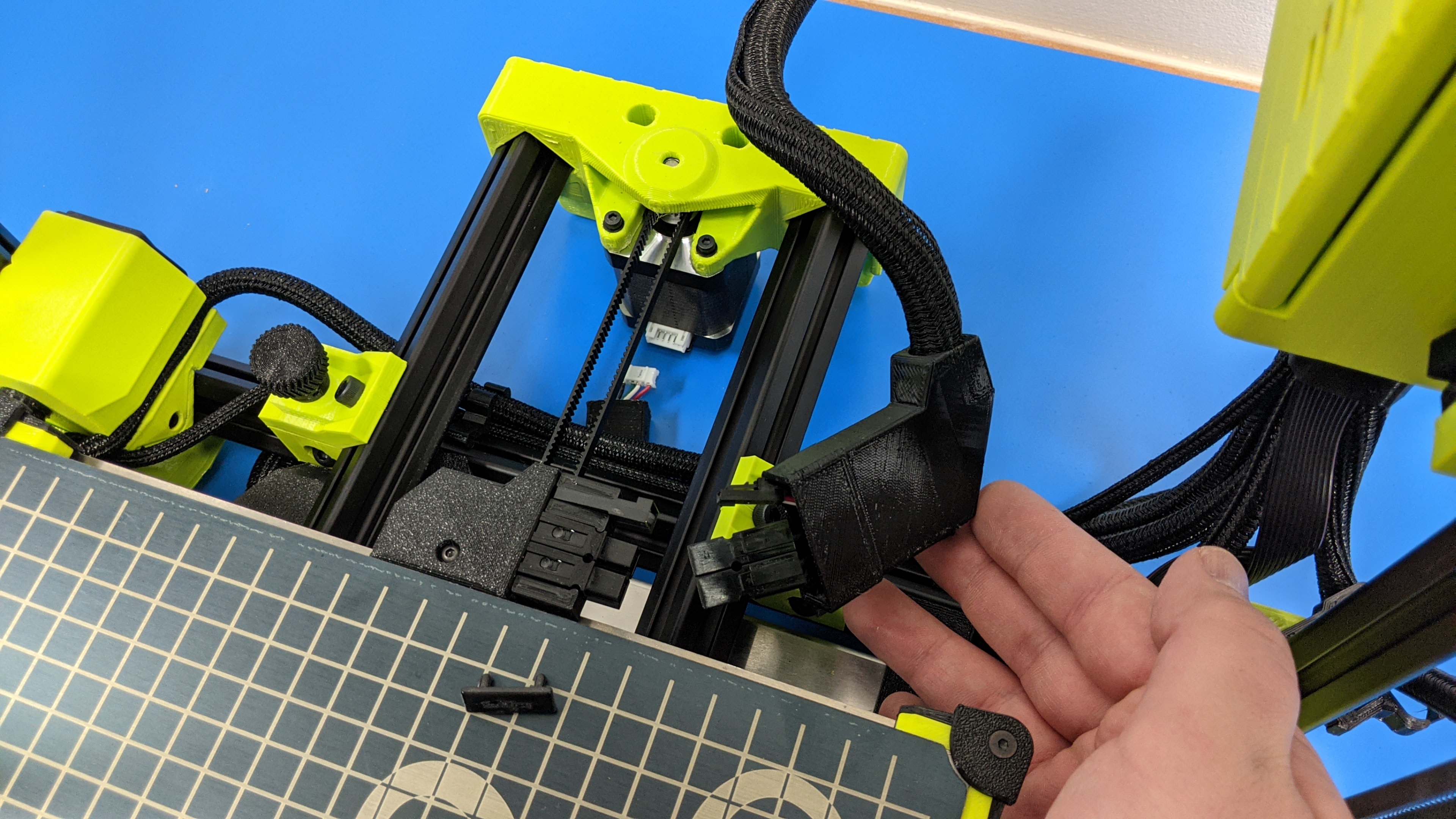
9B
Locate the two connectors for the bed heater and thermistor and connect.
Connect the y-axis motor connector.
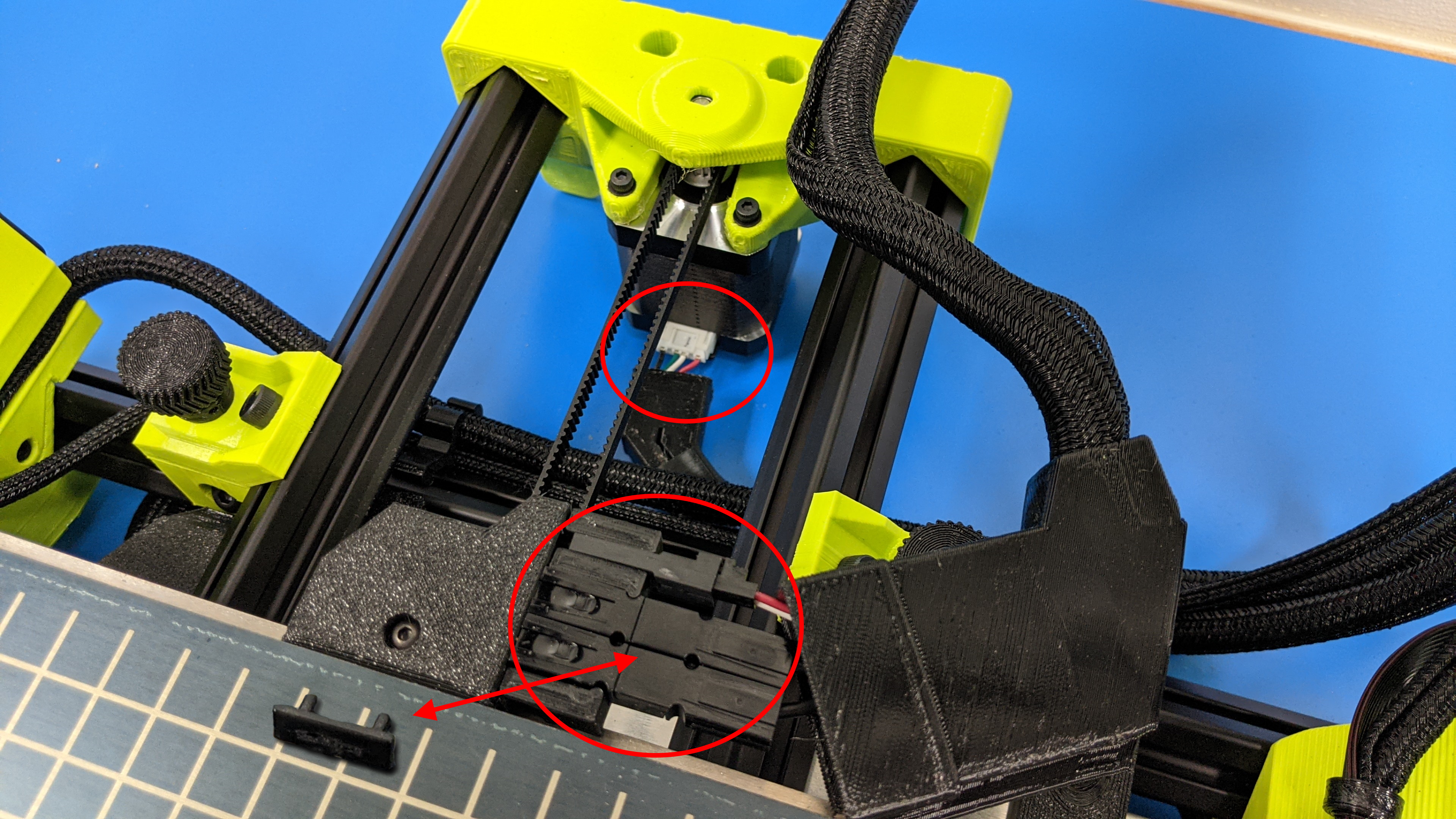
9C
Install the bed heater connector retention clip from the Anderson connector.
9D
Slide the cable covers onto the two y-axis bed connectors and y-axis motor connector.
10A
Install the 3 thumb screws holding the tool head on.
Two screws are located at the top of the tool x-carriage, one is located on the back of the carriage.
10B
Connect the tool head harness.
Be sure to save all packaging, including the foam and orange components as these can be used in the future for transporting your printer securely.
Want extra or replacement packaging material? Contact our sales team by sending an email to: Sales@LulzBot.com. Due to the custom nature of the shipping material, replacements are available for purchase only.
If you have any questions regarding your TAZ SideKick packaging, you can reach out to our support team by sending an email to: support@lulzbot.com.
If you no longer have the 3d printed shipping components, you can find the stl files at our gitlab page located here.