Open HardwareAssembly Instructions
Guides for installation and assembly of the LulzBot line of products made by FAME 3D LLC.
Guides for installation and assembly of the LulzBot line of products made by FAME 3D LLC.
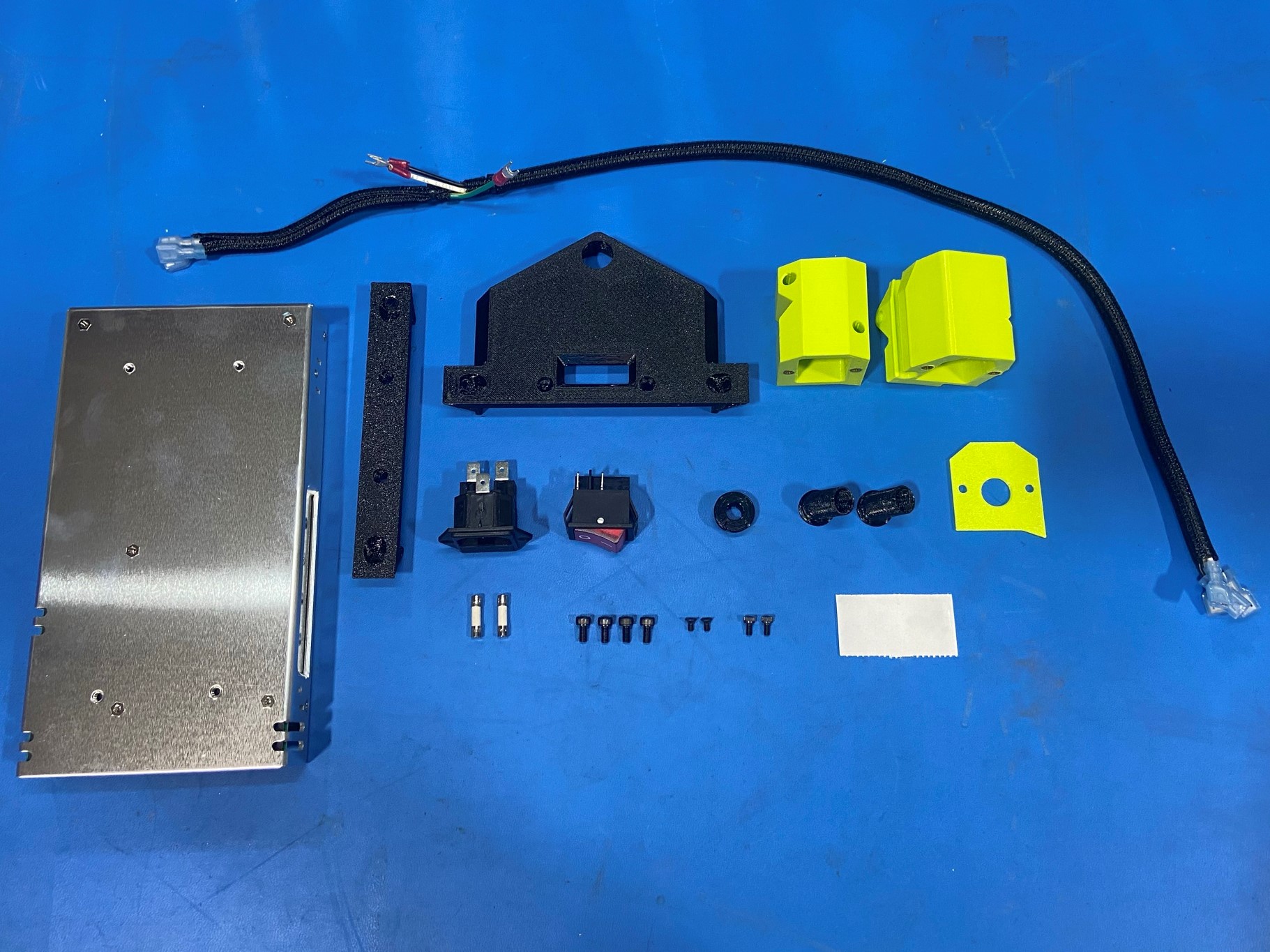
2x- [HD-BT0045] M3x6 SHCS, Black-Oxide
2x- [HD-BT0128] M3x6 FHCS, Black-Oxide
4x- [HD-BT0267] M4x8 SHCS, Black-Oxide
2x- [EL-MS0414] 250V 3.15A Slo-Blo Cartridge fuses
1x- [EL-PS0046] 350W Meanwell Power Supply
1x- [EL-SW0023] Rocker Switch 20A 250V
1x- [AS-CB0127] Power Cord to Switch-GND Harness (747)
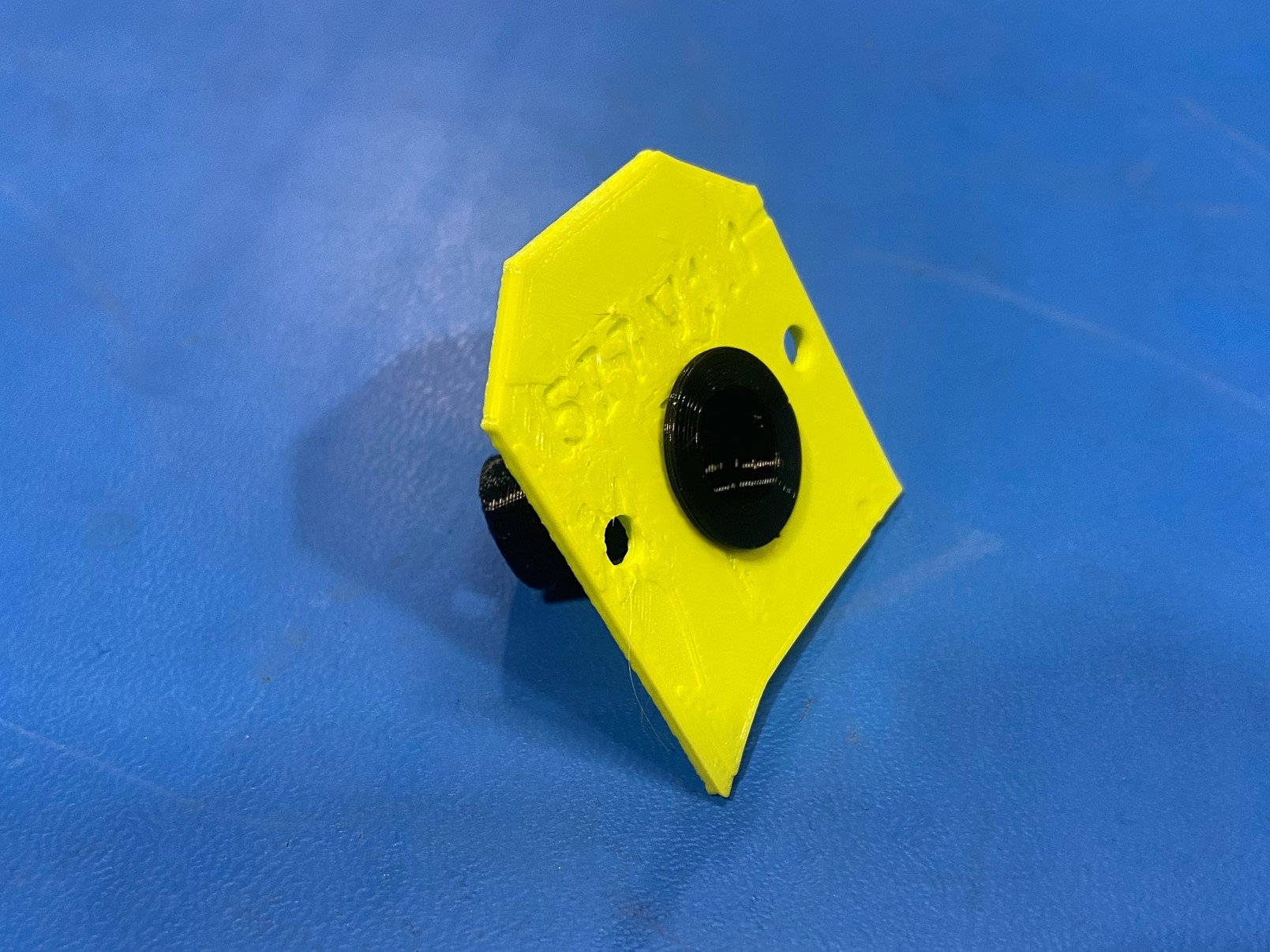
1x- [PP-GP0576] Z Flexy Power Supply Grommet
1x- [PP-GP0577] Z Power Switch Housing Cover (Green) (Black)
1x- [PP-GP0583] Z Power Switch Housing (Green) (Black)
1x- [PP-GP0585] Z Electrical Plug Housing (Green) (Black)
2x- [PP-GP0598] Flexy EH PSH Strain Relief
1x- [PP-GP0605] Z 747 Power Supply Cover
1x- [PP-GP0606] Z 747 Power Supply Mount
1x- [PP-MP0028] AC power entry module
1x- TAZ 747 SideKick Serial Number
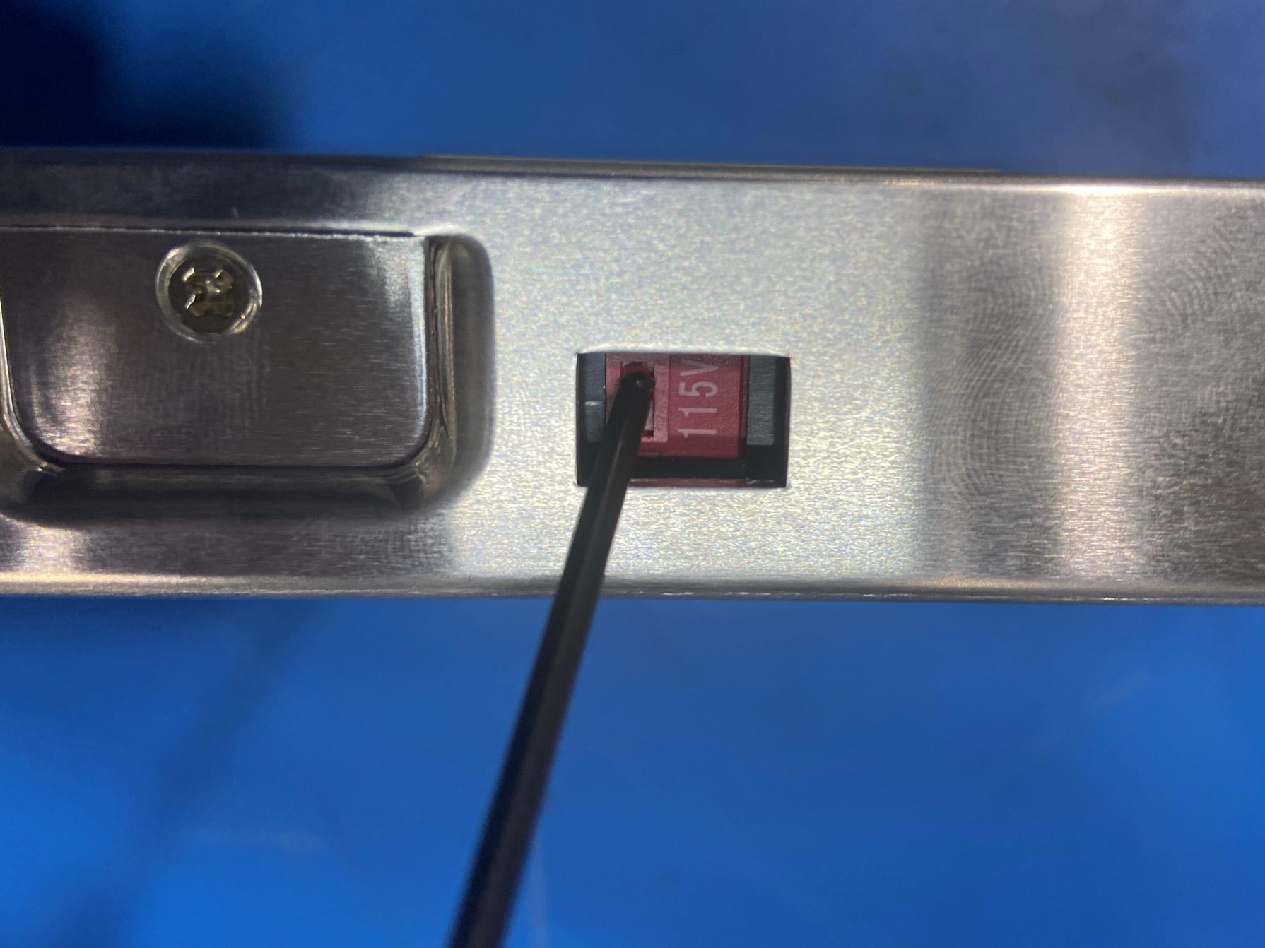
Using a screw driver slide the red switch on the side of the 350W Meanwell power supply [EL-PS0046] from 230V to 115V
Now place the TAZ 747 SideKick serial number on the power supply making sure the serial number is visible through the Z 747 power supply cover [PP-GP0605].
Next use 2x M4x8 SHCS [HD-BT0267] to mount the Z 747 power supply cover to the Meanwell power supply.
Then attach the Z 747 power supply mount [PP-GP0606] to the Meanwell power supply using 2x M4x8 SHCS.
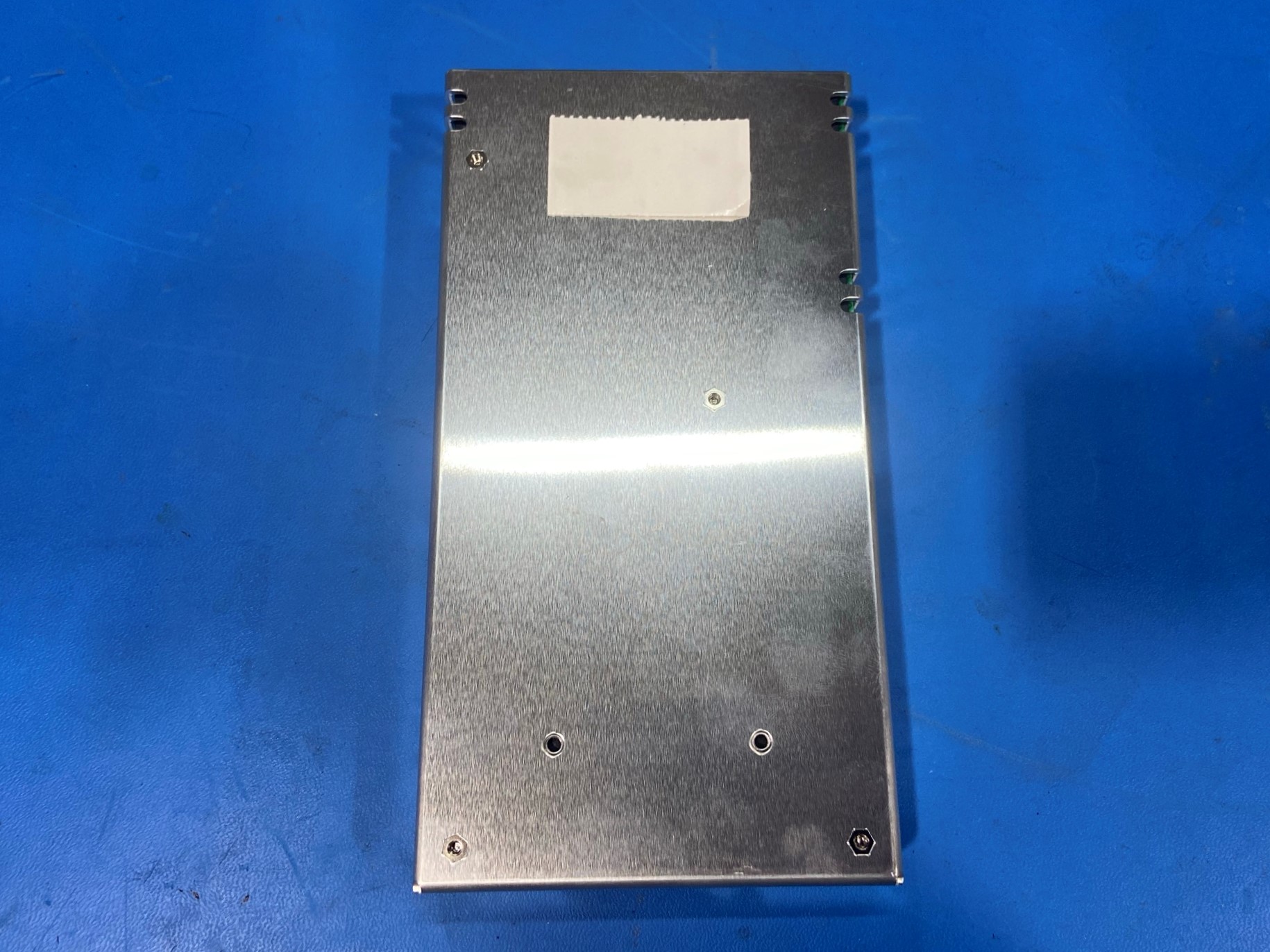


Flip the Meanwell power supply over and feed the shorter end of the power cord to switch wire harness [AS-CB0118] through the hole on the Z 289 power supply cover.
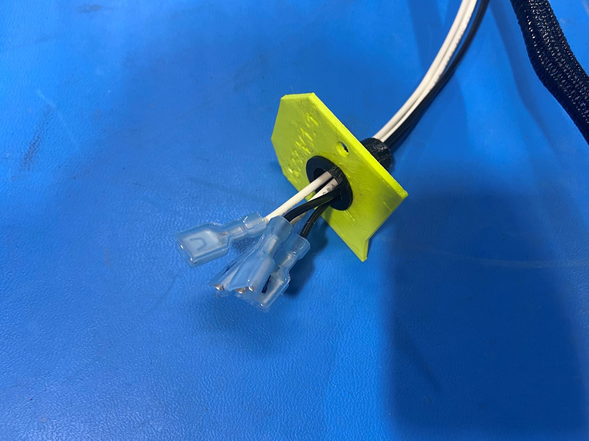
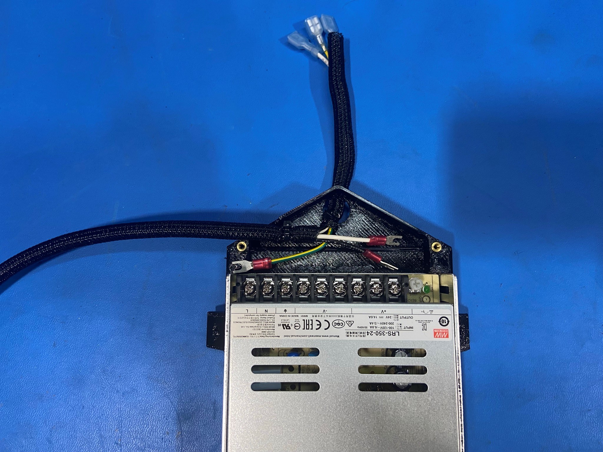
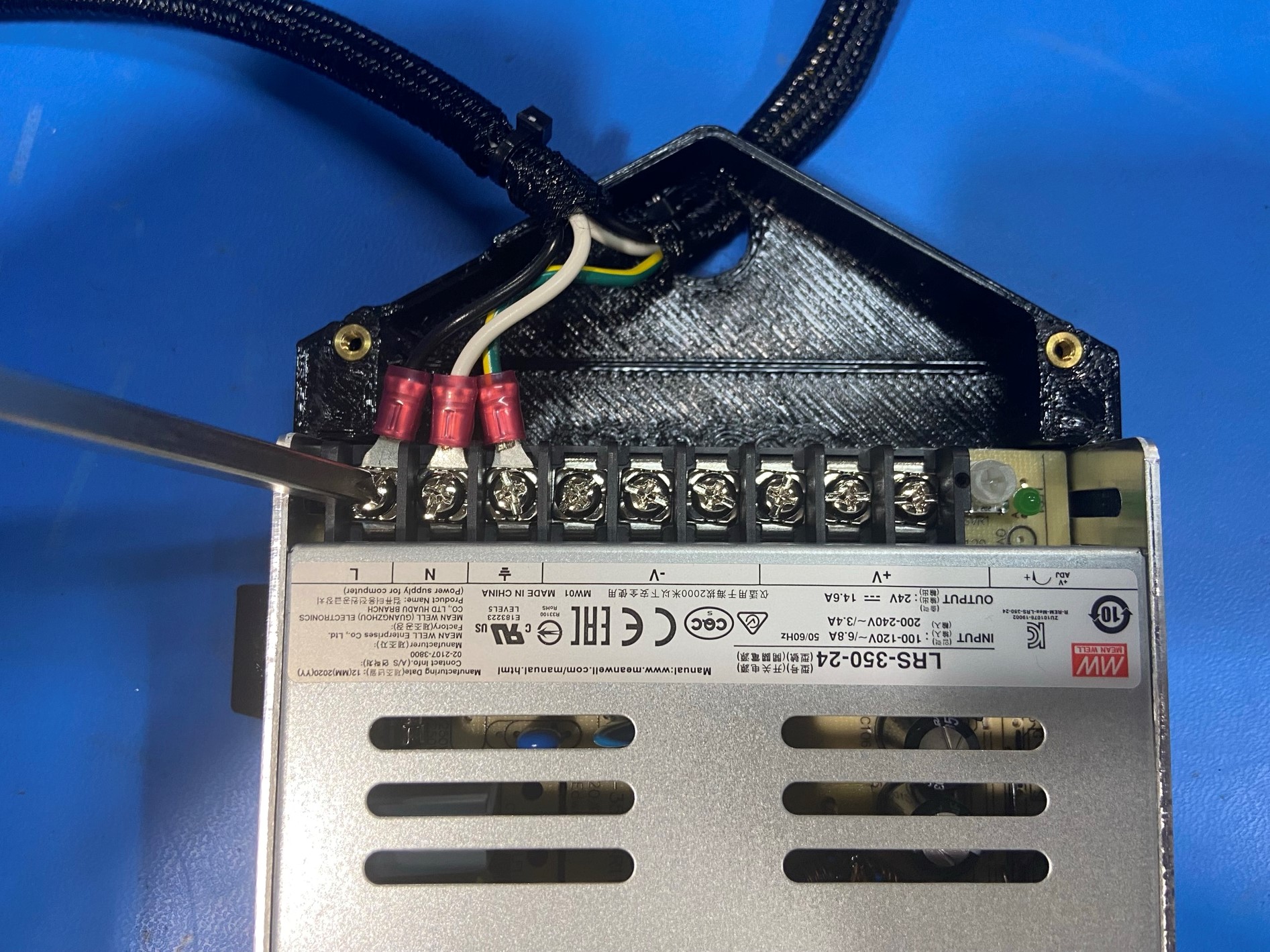
Next, loosen the three phillips screws on the left side of the power supply (⏚,N, and L), then slide the black wire under the "L" screw, white wire under the "N" screw and the green wire under the " ⏚".
Then tighten the three screws and tug on the wires to verify that they are secure.
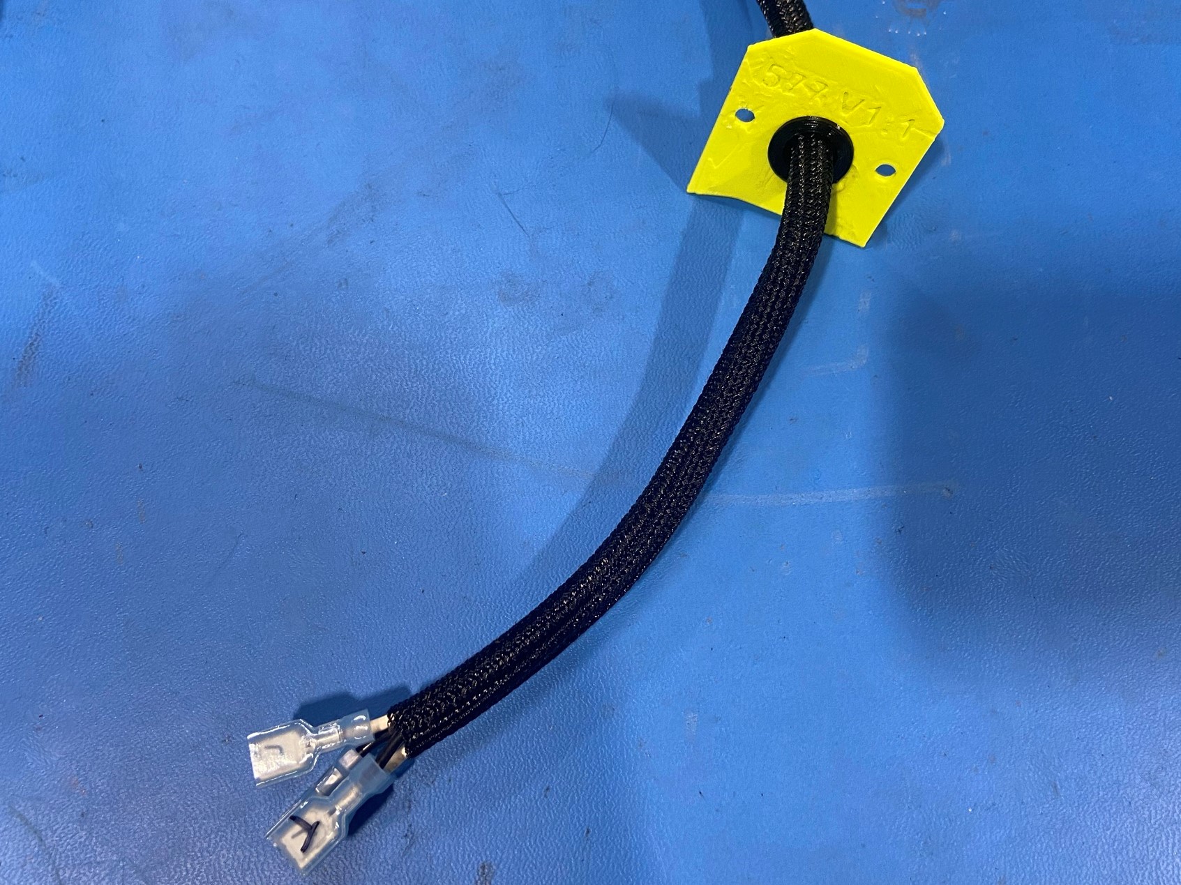
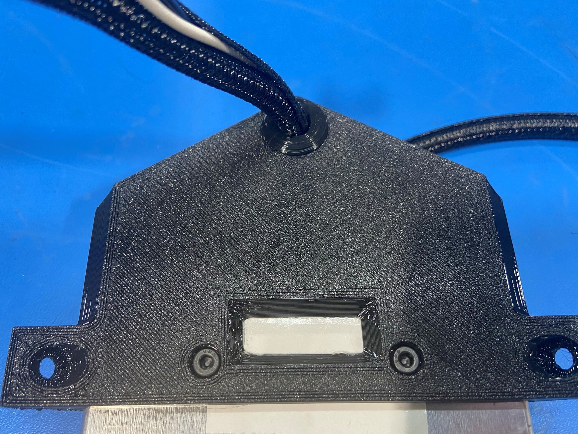
Now pull the Z flexy power supply grommet [PP-GP0576] apart and slide it over the shorter side of the wire harness [reference#1]. Push the grommet in place making sure the top lays flat on the power supply cover.
Note: Make sure the flat side of the grommet is facing up

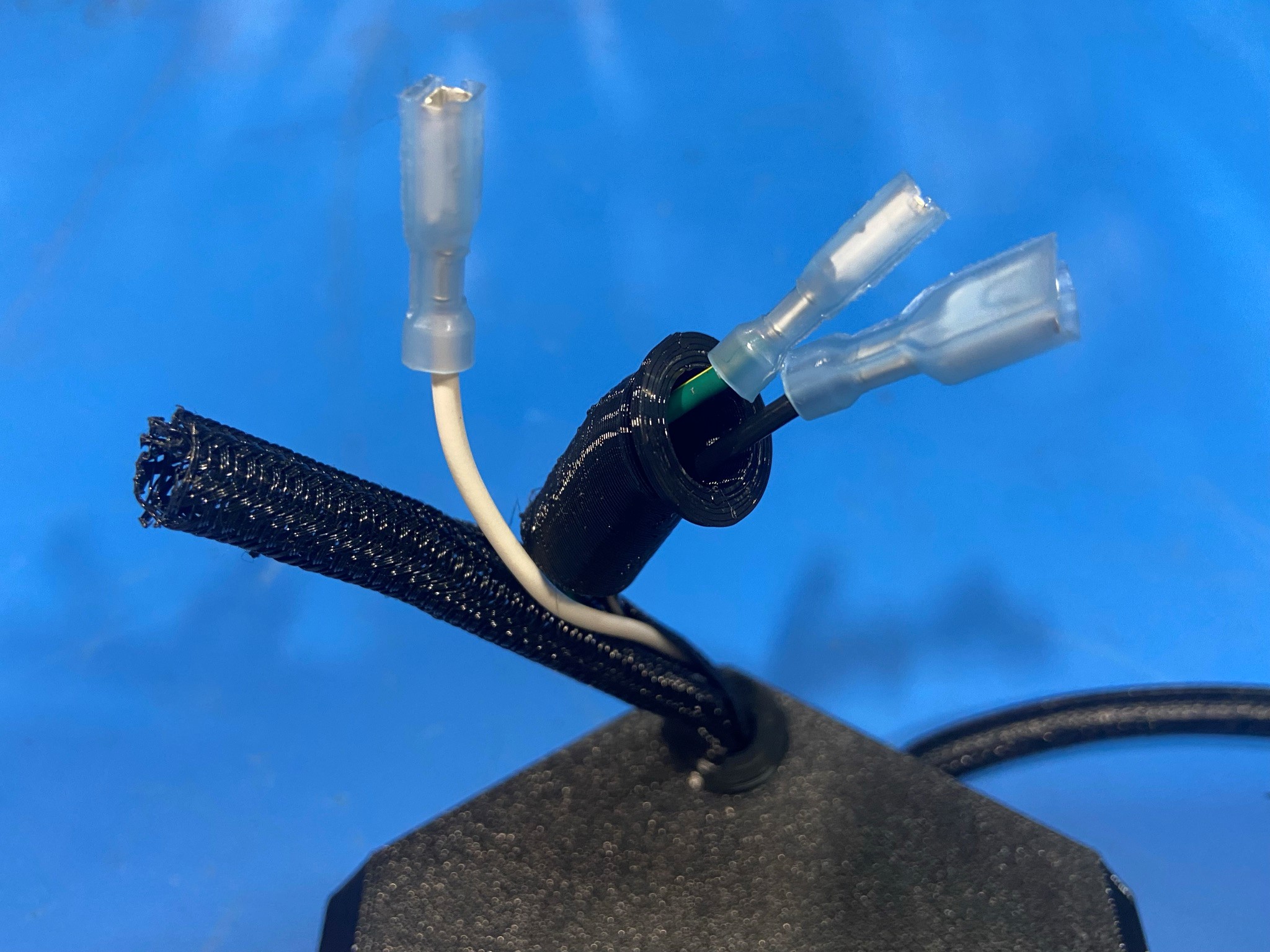
Remove the three wires from the braid on the short side of the wire harness. Then taking one at a time slide them through flexy EH PSH strain relief [PP-GP0598] start with the narrow side of the strain relief.
Once all three wires are through the stain relief replace the braid around the wires and slide the braid through the stain relief.
Now slide the Z Electrical Plug Housing [PP-GP0585] over the wires starting with the circular hole on the back side of the housing.
Connect the three wires to the back side of the AC power entry module [PP-MP0028] follow [reference#2] for placement guild for the three wires. Once all three wires are mounted bend the bottom two wires up and the top wire down so they are aligned with the hole on the backside of the housing.
Then push on the stain relief till it is locked into place on the electrical plug housing.
Note: follow [reference#3] for orientation of the strain relief bend
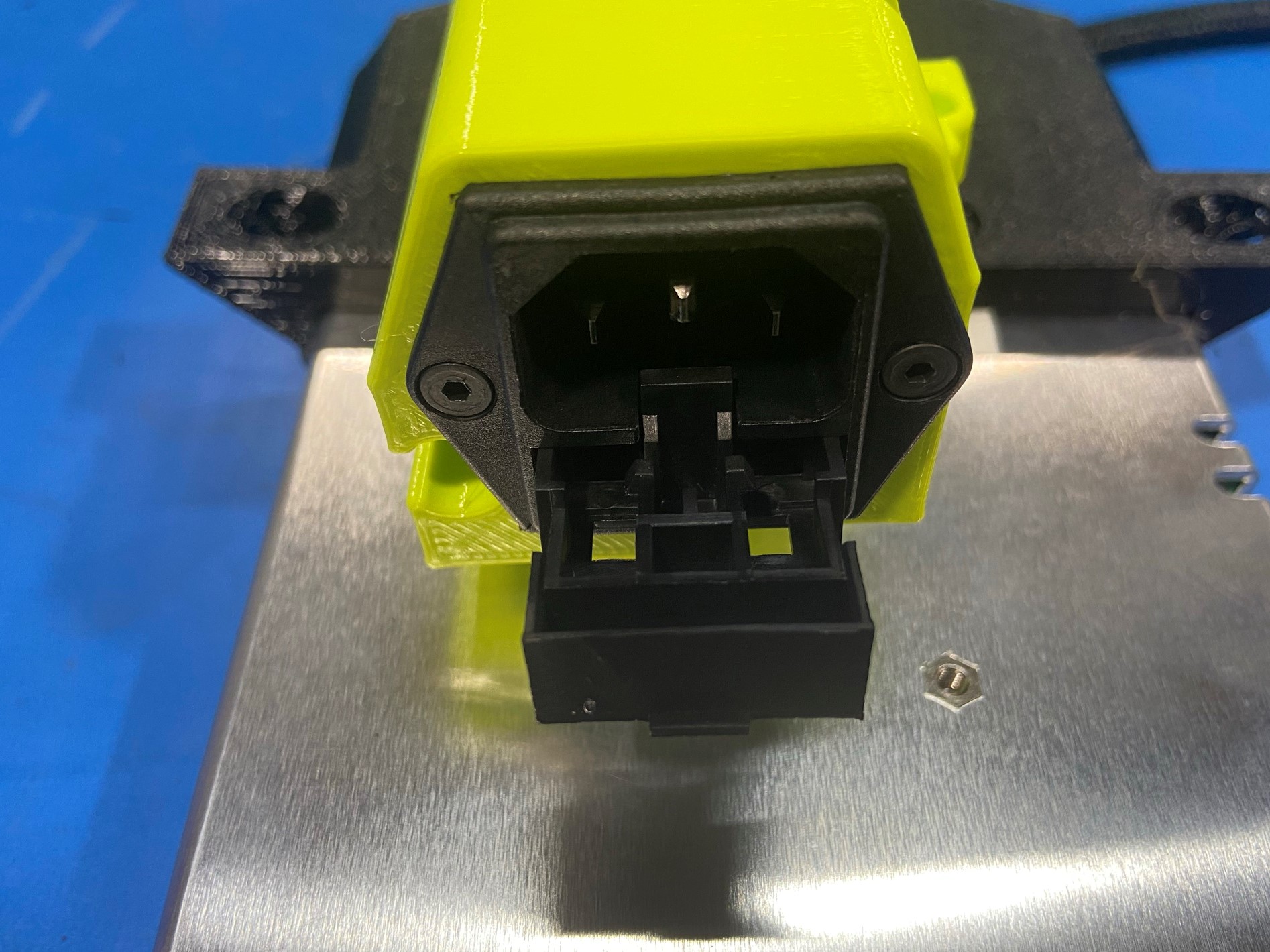
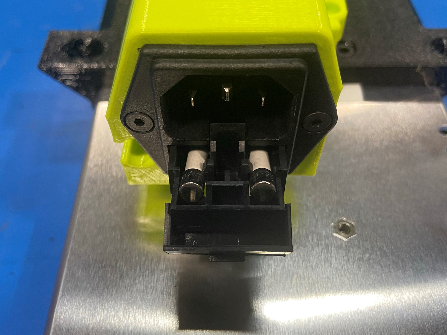
Then using 2x M3x6 FHCS [HD-BT0128] mount the power entry module to the electrical plug housing. Once mounted pull the tray out on the front of the power entry module and place 2x 250V 3.15A Slo-Blo cartridge fuses [EL-MS0414] into the two slots, then close the tray
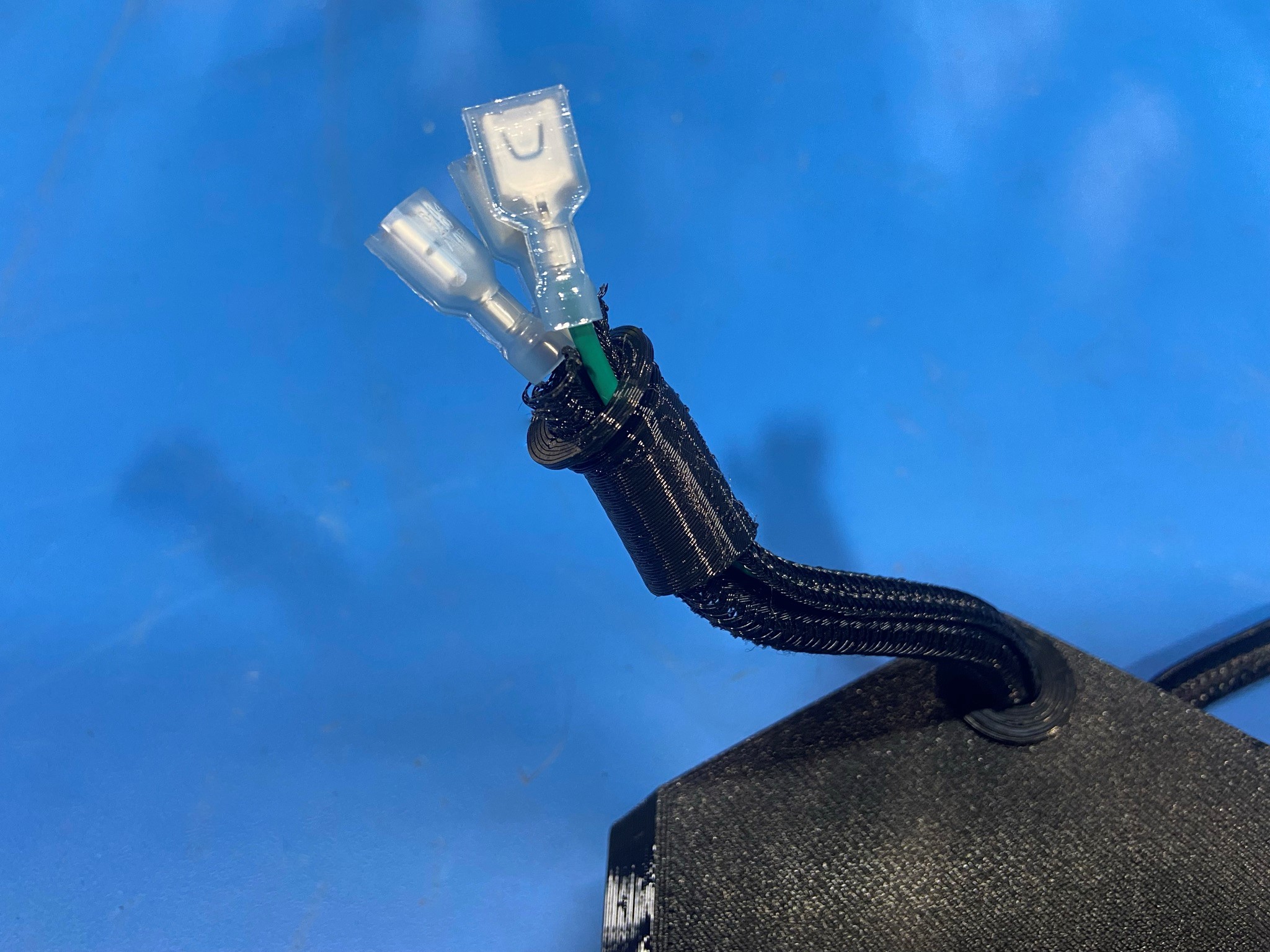


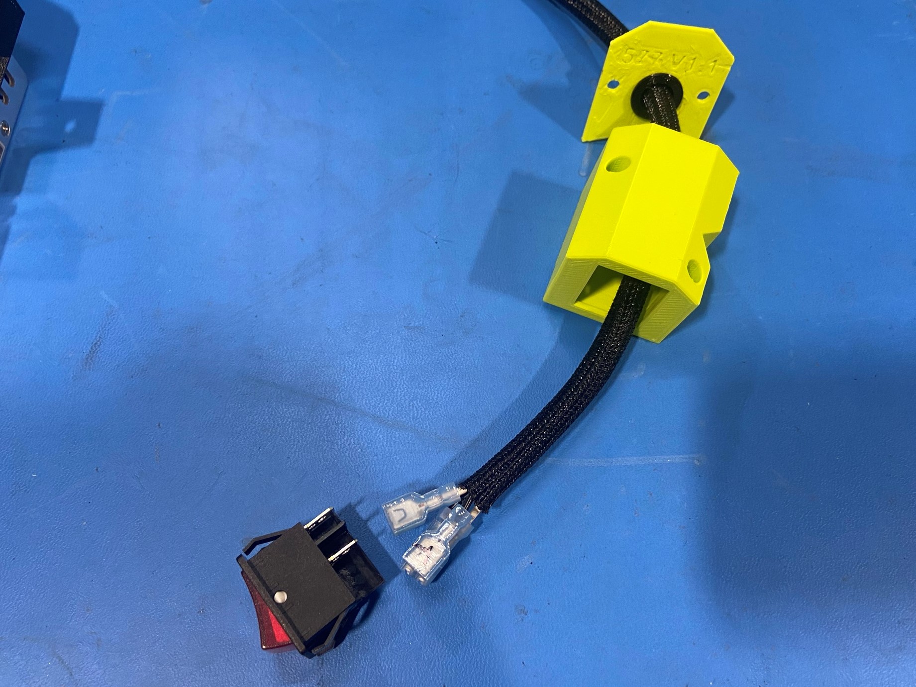
Take the four wires out of the wire braid, then push the flexy EH PSH strain relief [PP-GP0598] through the Z power switch housing cover [PP-GP0577] making sure the strain relief sticks out on the opposite side of the numbers on the power switch housing cover.
Then slide all four wires through the strain relief and housing cover one wire at a time. Once all four wires are through place all four wire back in the wire braid and side the braid through the plastic parts.
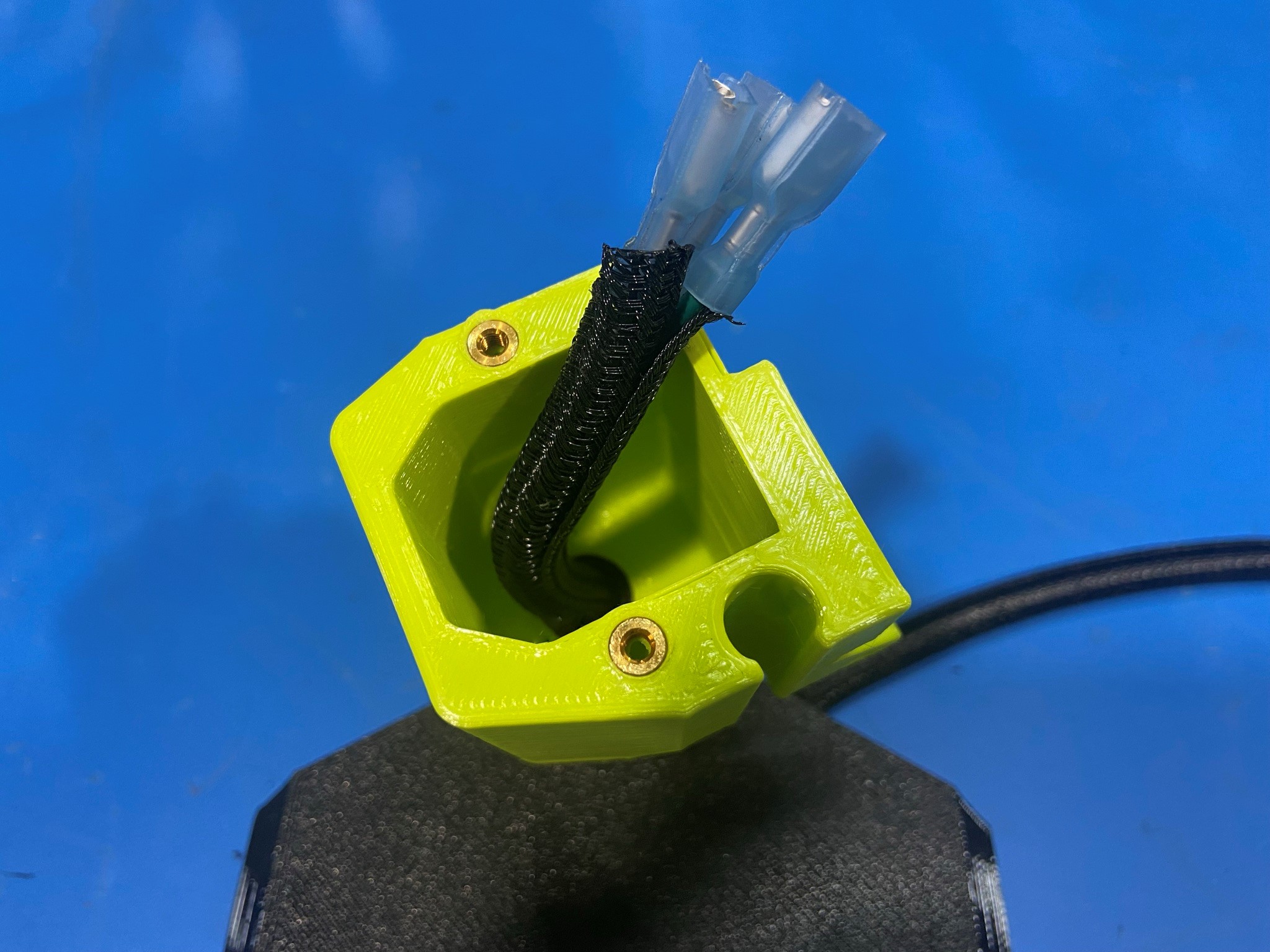
Then feed the wires through the Z power switch housing [PP-GP0583] making sure to start with the side with two inserts.
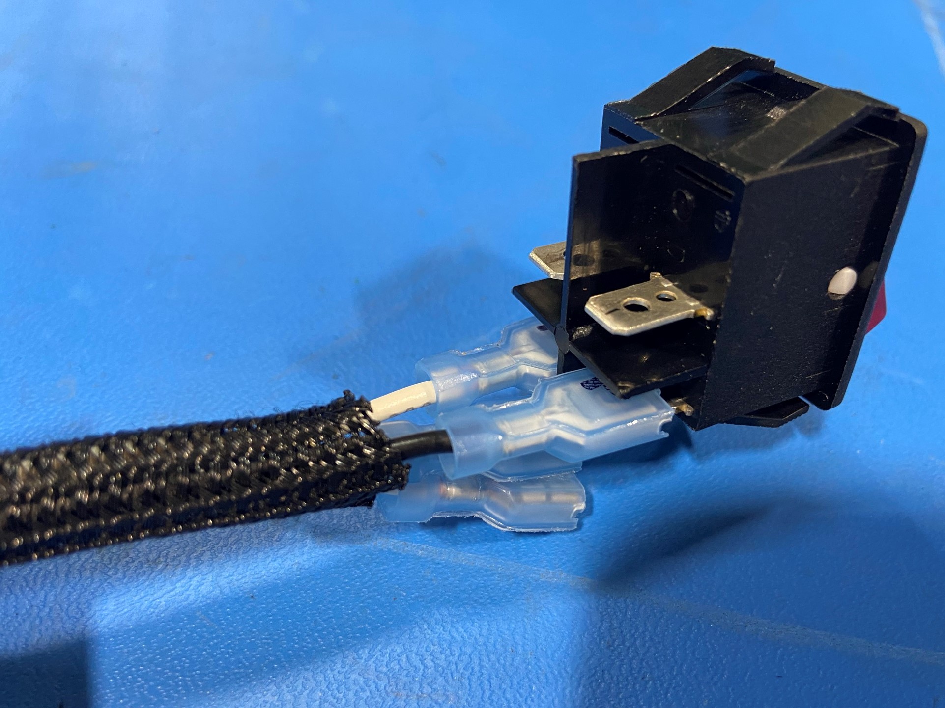
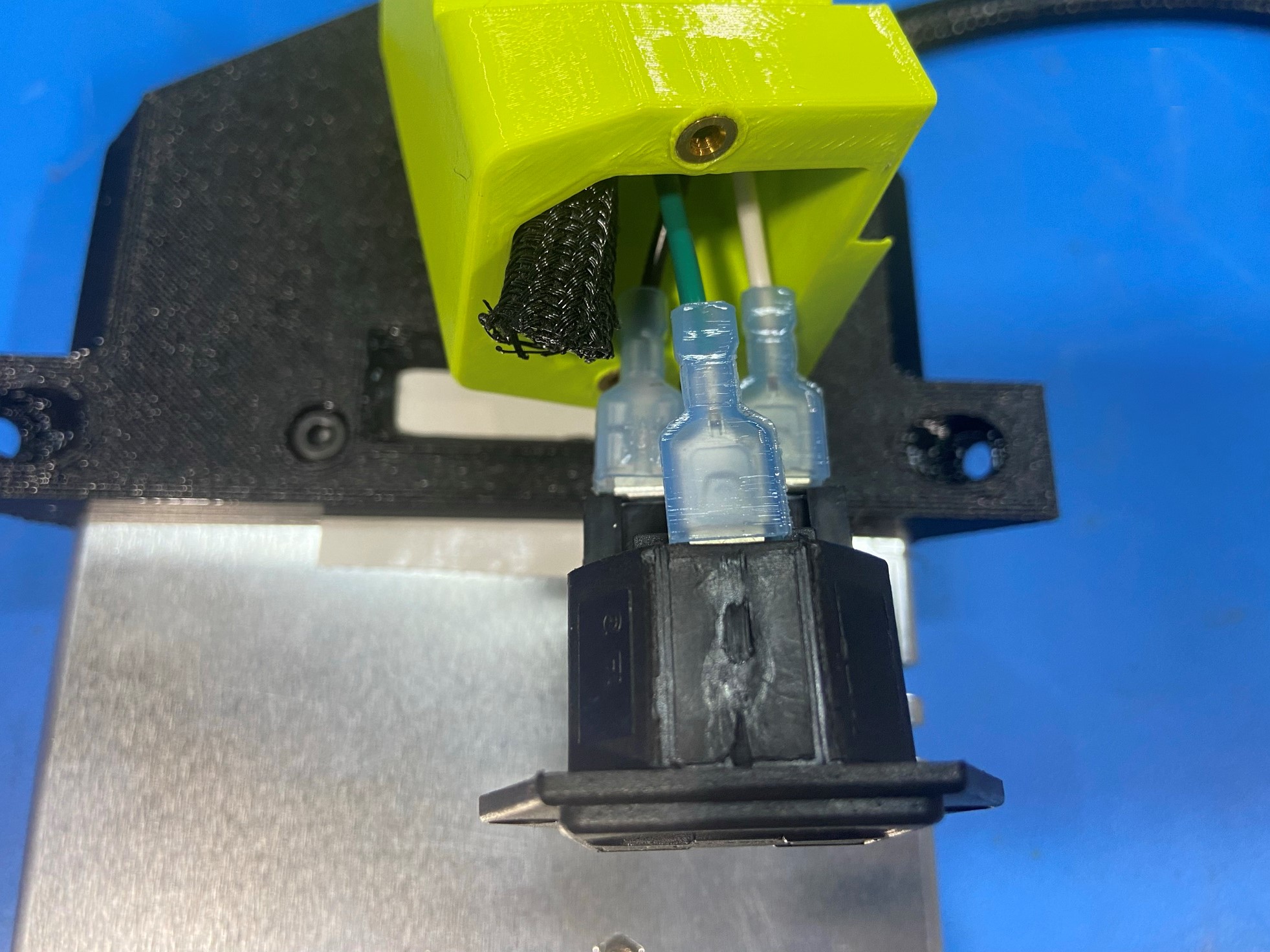
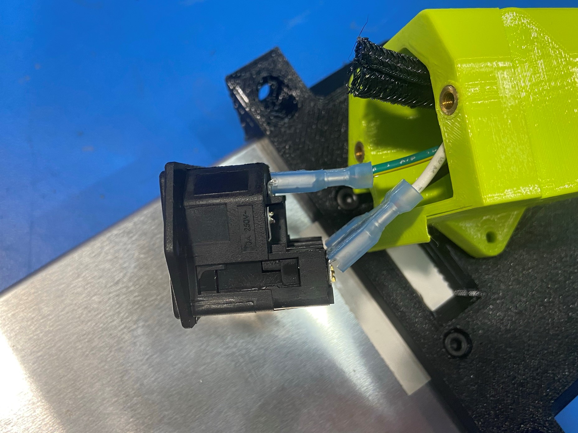
Now take the black and white wires that have a black mark on the connectors and slide them onto the rocker switch 20A 250V [EL-SW0023] following [reference#4] for placement guild.
Then take the other two wires and attach them to the top two tabs matching the colors to the bottom two tabs [reference#5]
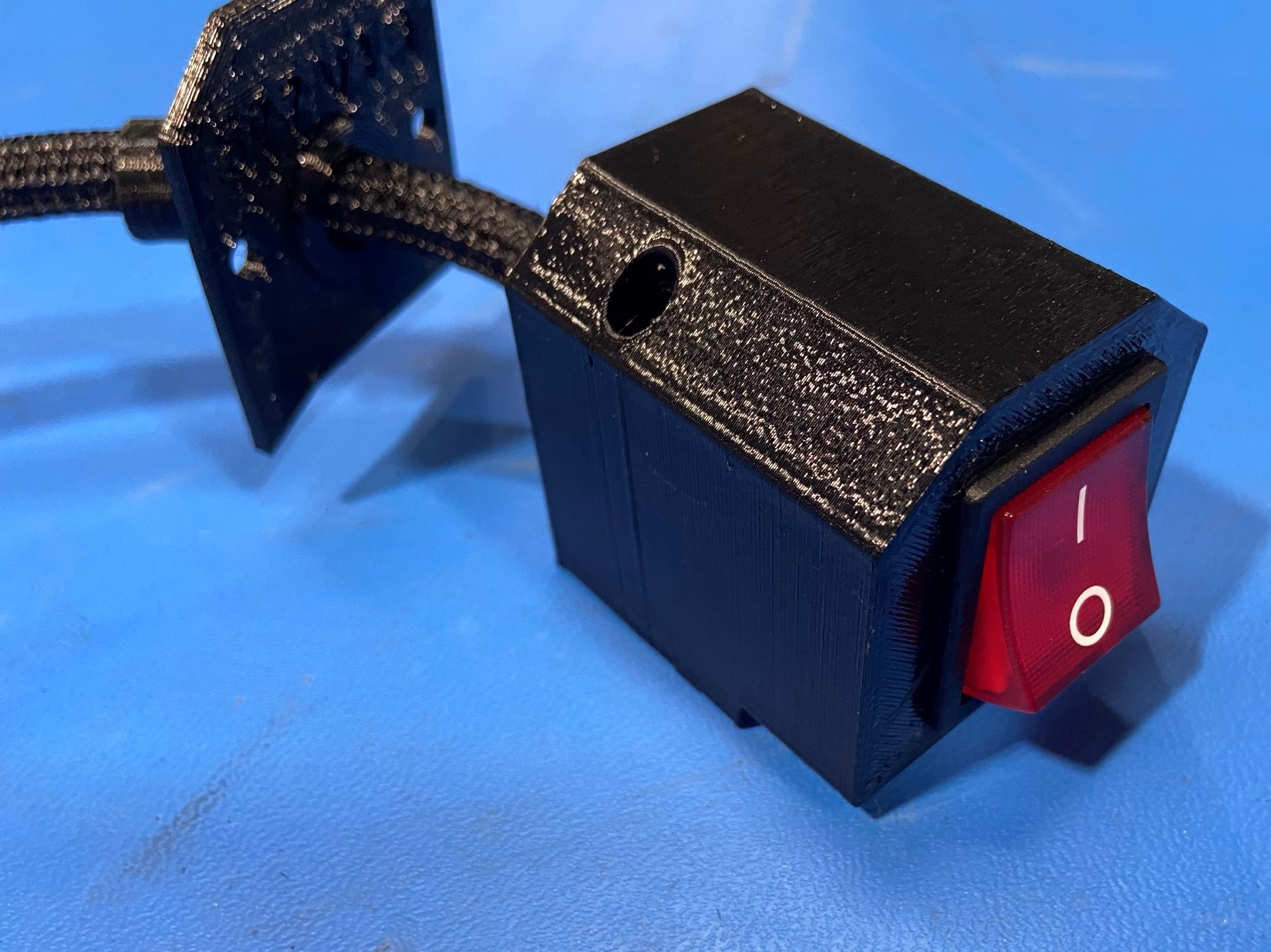
Press the rocker switch inside the power switch housing until it snaps in place then using 2x M3x6 SHCS [HD-BT0045] attach the switch cover to the switch housing