Open HardwareAssembly Instructions
Guides for installation and assembly of the LulzBot line of products made by FAME 3D LLC.
Guides for installation and assembly of the LulzBot line of products made by FAME 3D LLC.
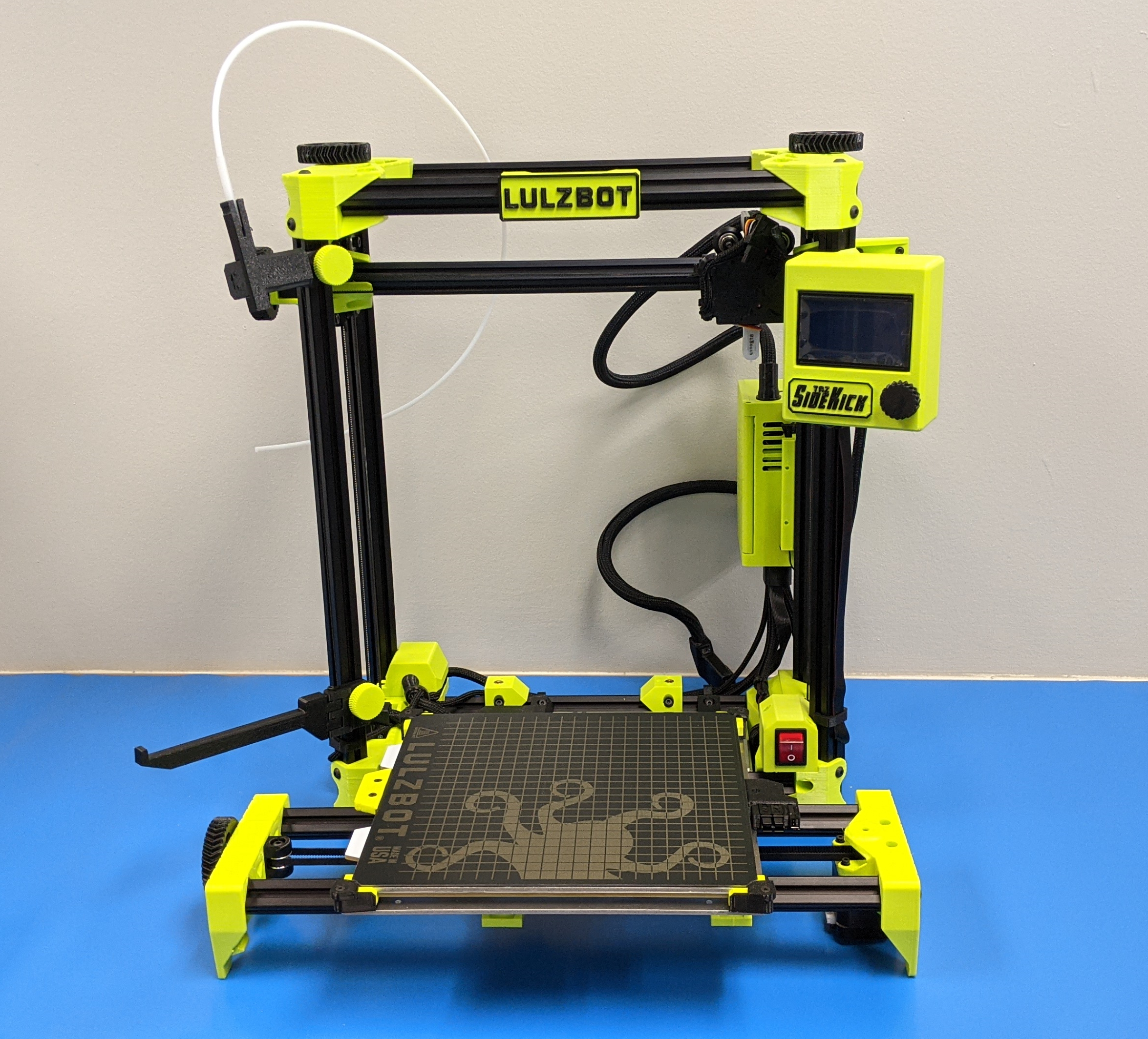
Need to ship or travel with your LulzBot TAZ SideKick? Follow the instructions below to properly secure your TAZ 3D printer.
Want extra or replacement packaging material? Contact our sales team by sending an email to: Sales@LulzBot.com. Due to the custom nature of the shipping material, replacements are available for purchase only.
Note: Failure to use the original packaging material when returning a 3D printer for warranty service will cause delays and may require additional charges.
Printers that are received without the original packaging materials may be returned to sender.
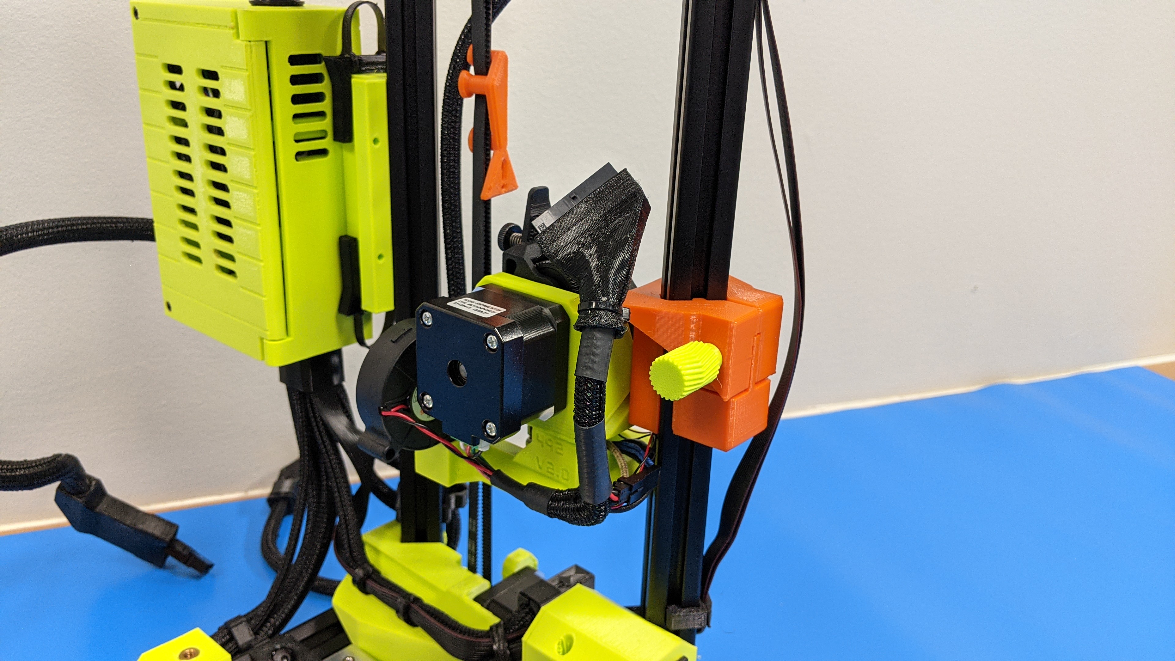
2A
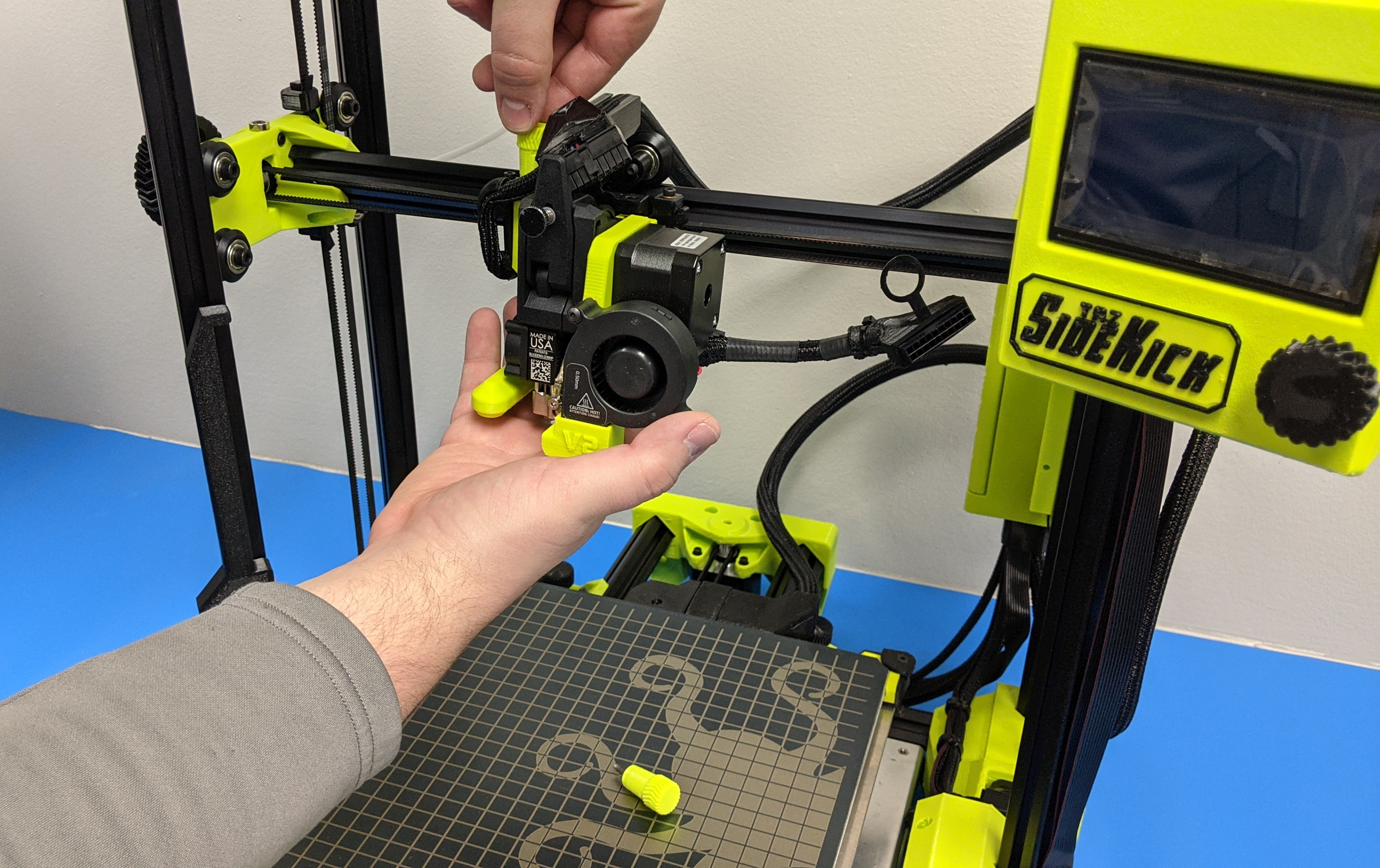
Disconnect the tool head harness.
2B
Unscrew the 3 thumb screws holding the tool head on.
Two screws are located at the top of the tool x-carriage, one is located on the back of the carriage.


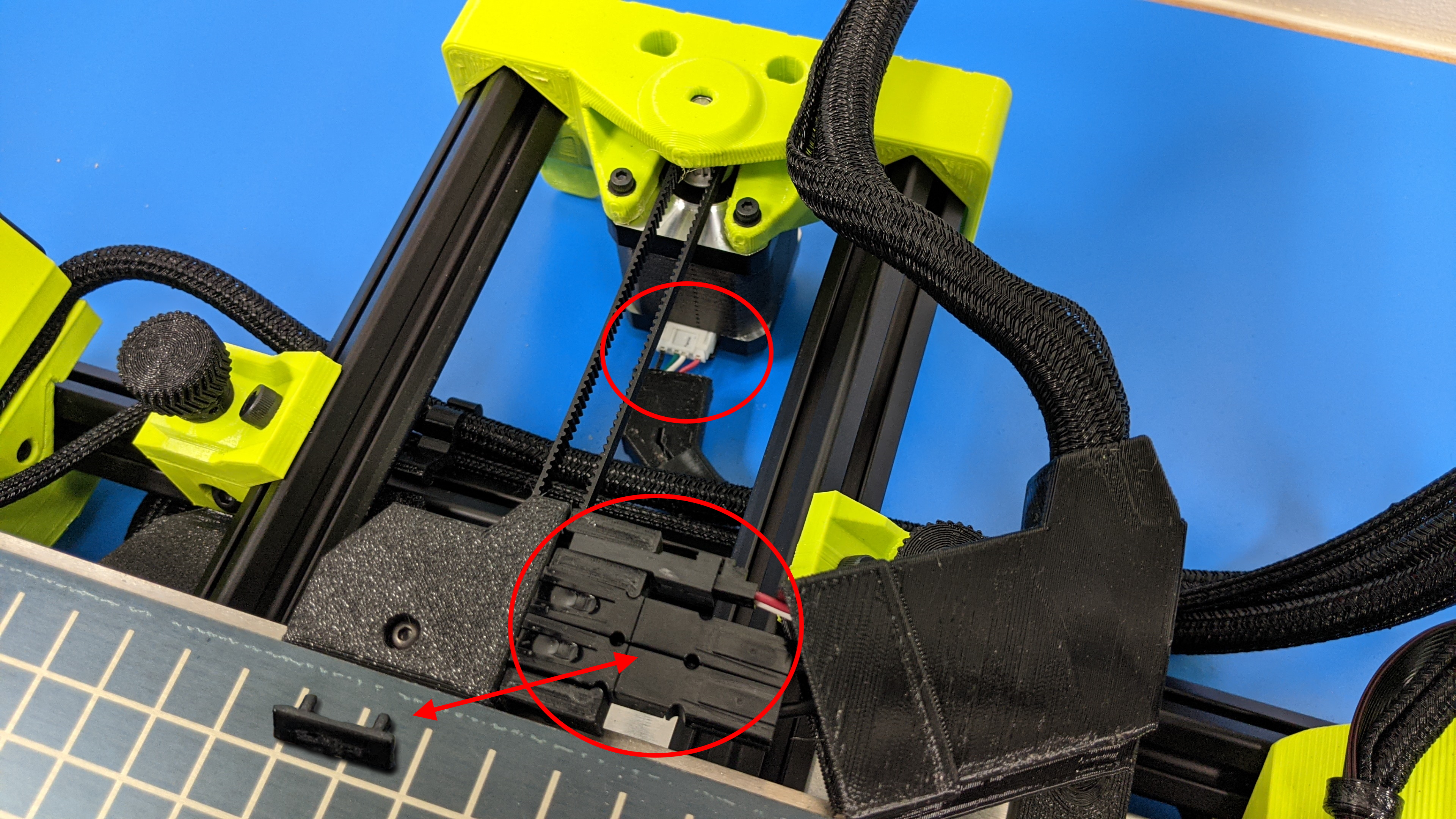
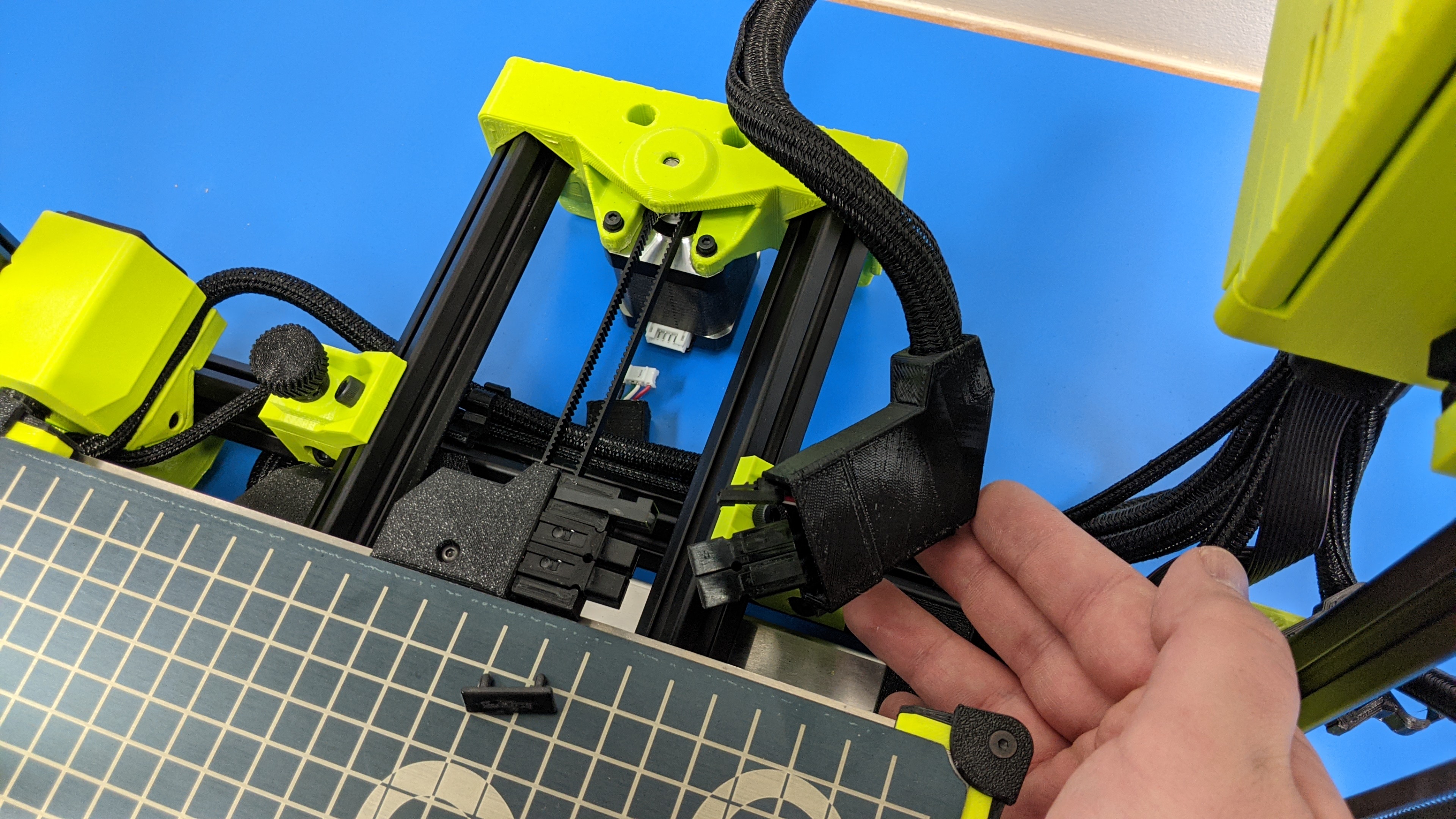
3A
Slide the cable covers off of the two y-axis bed connectors and y-axis motor connector.
3B
Remove the bed heater connector retention clip from the Anderson connector and set aside.
(Place the retention clip in a place it will not get lost or damaged)
3C
Disconnect the two connectors for the bed heater and thermistor.
Disconnect the y-axis motor connector.
3D
Remove the (4x) y-axis thumb screws holding the y-axis to the printer frame.
Set aside.
3E
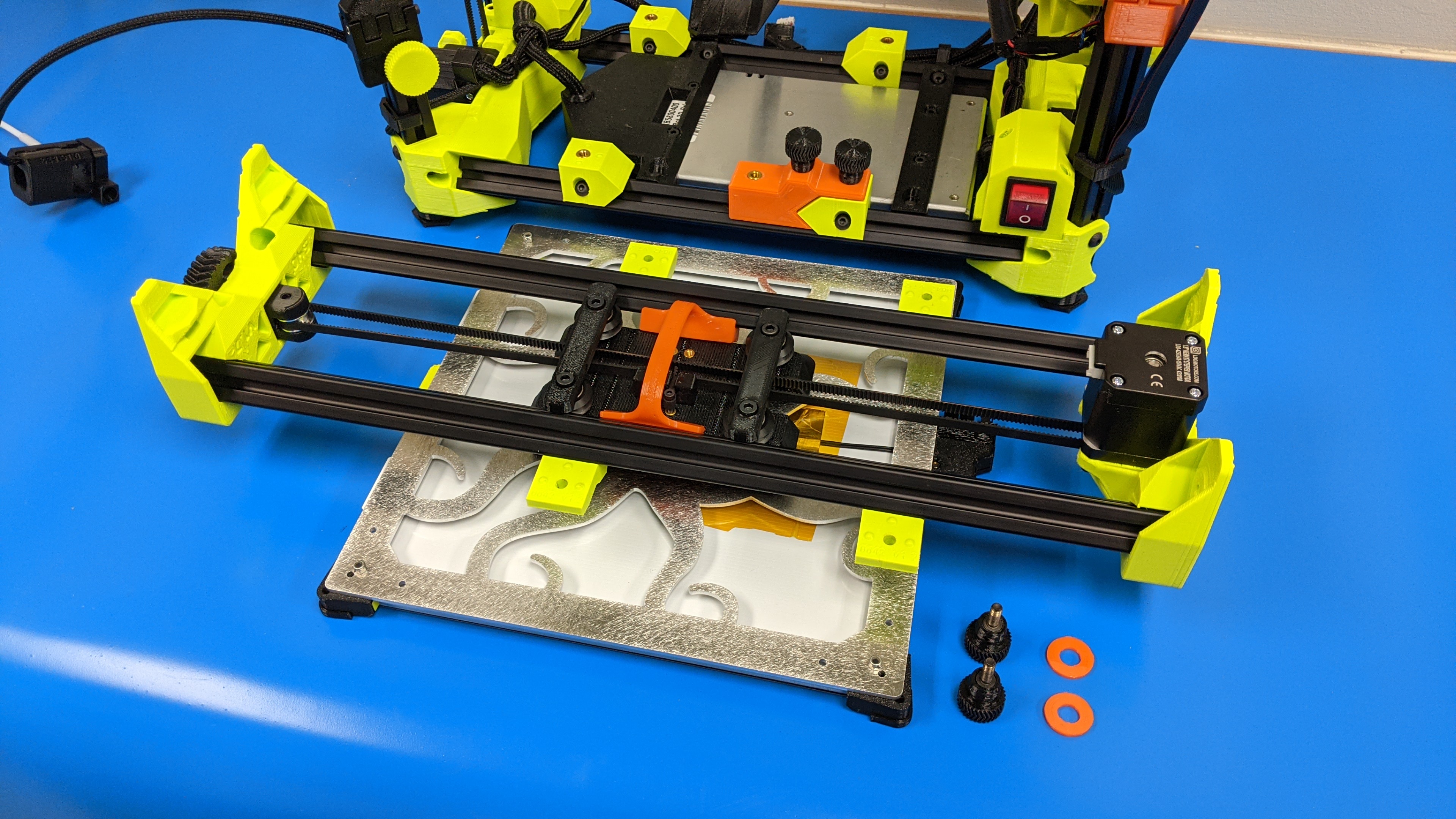
Remove the y-axis from the printer frame and set aside.

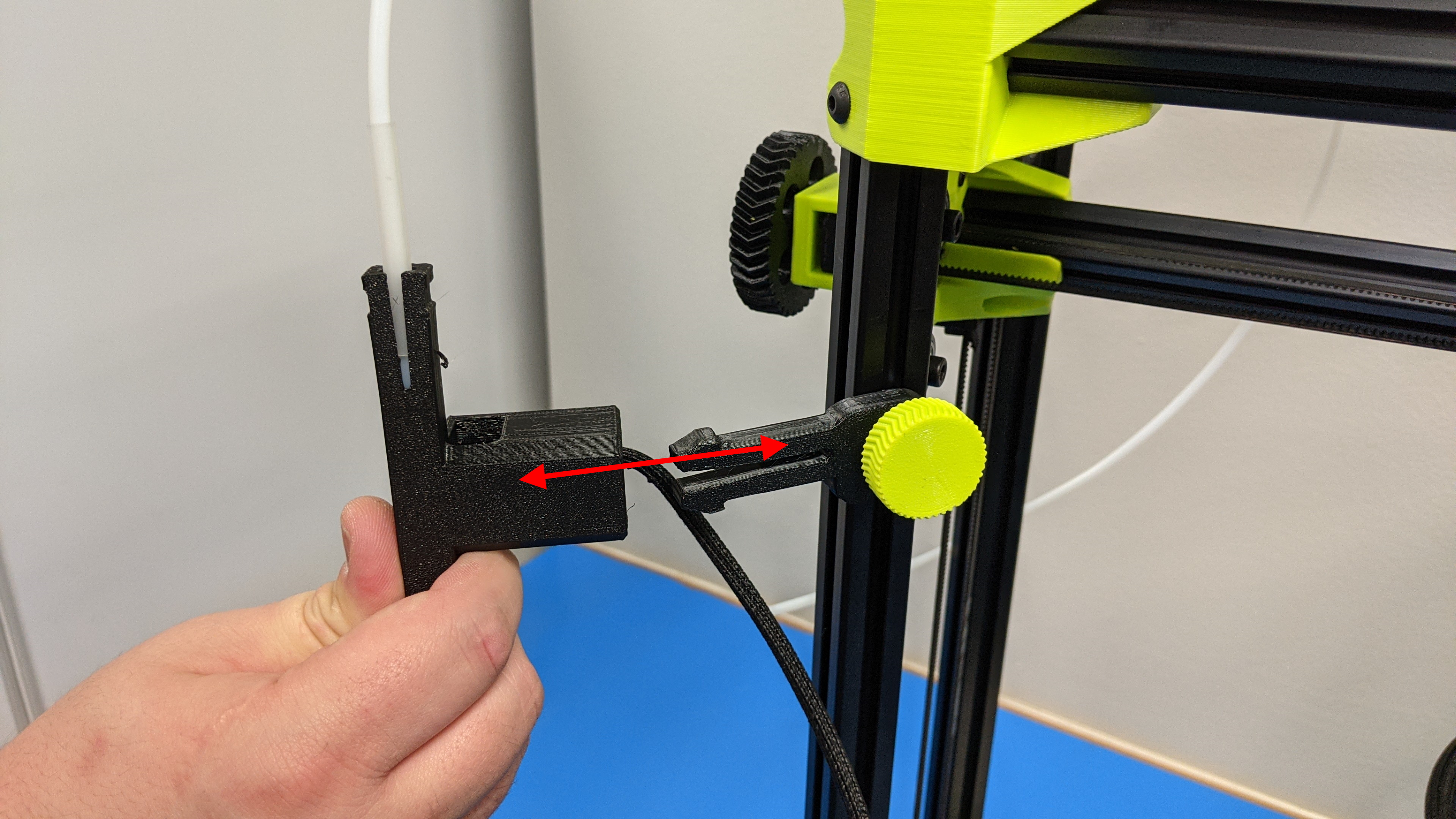
If your printer has a runout sensor installed, this will need to be removed before the filament spool and guide arm can be stowed away.
Depress the small clamps that hold the runout sensor on the guide arm and pull the runout sensor off of the arm.
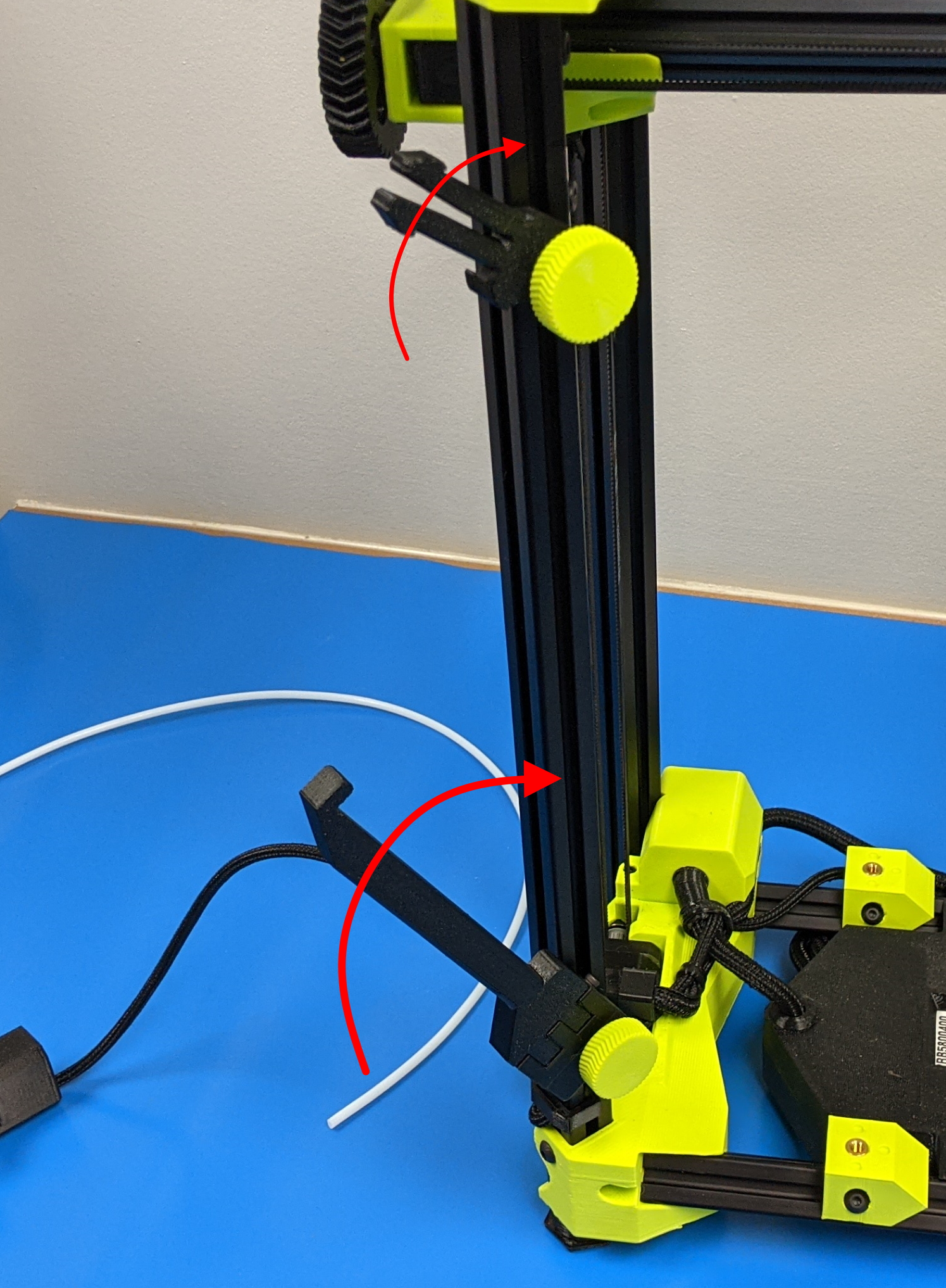
Stow away the filament spool arm as well as the filament guide arm by rotating them into their upward position.
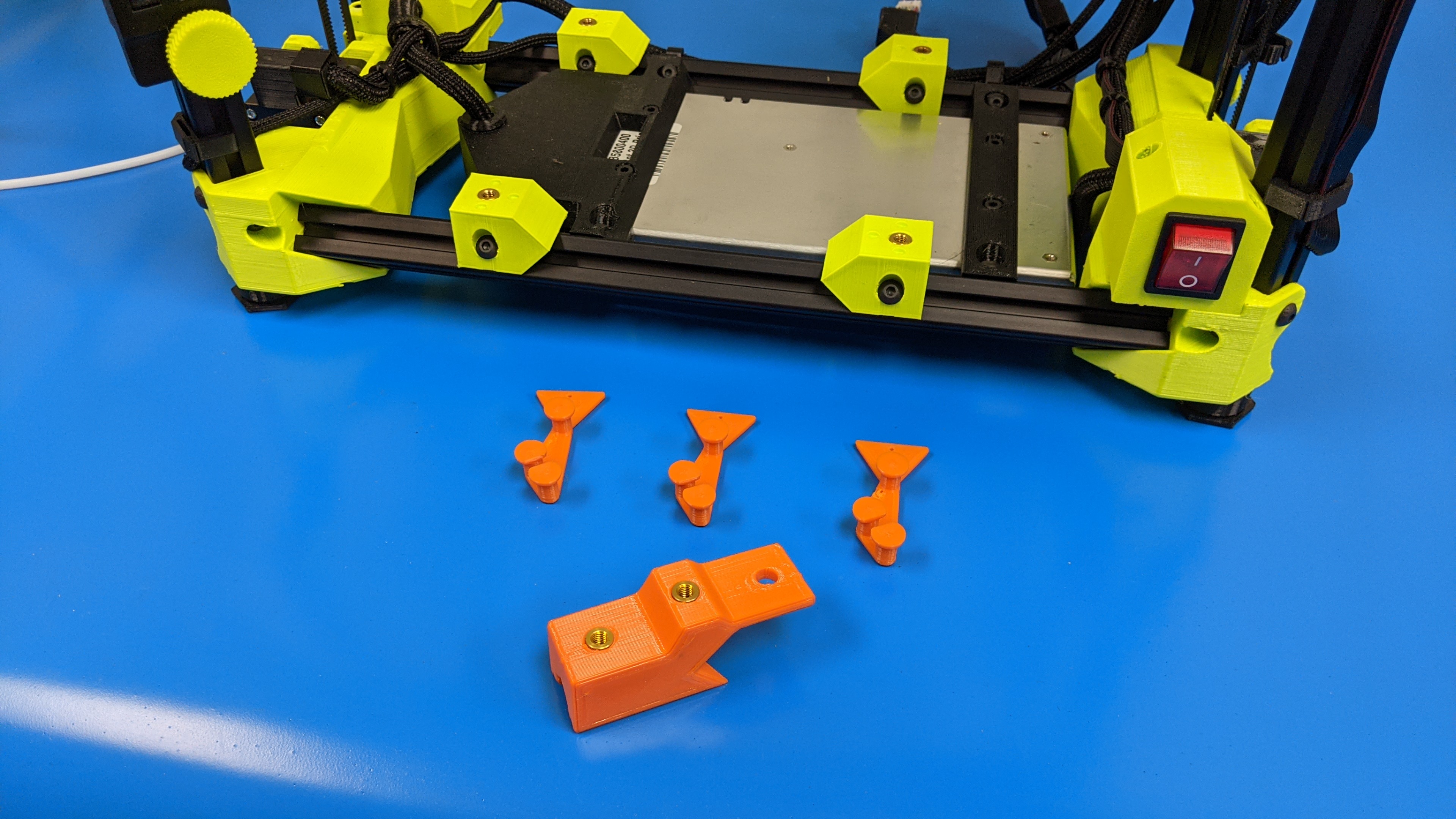
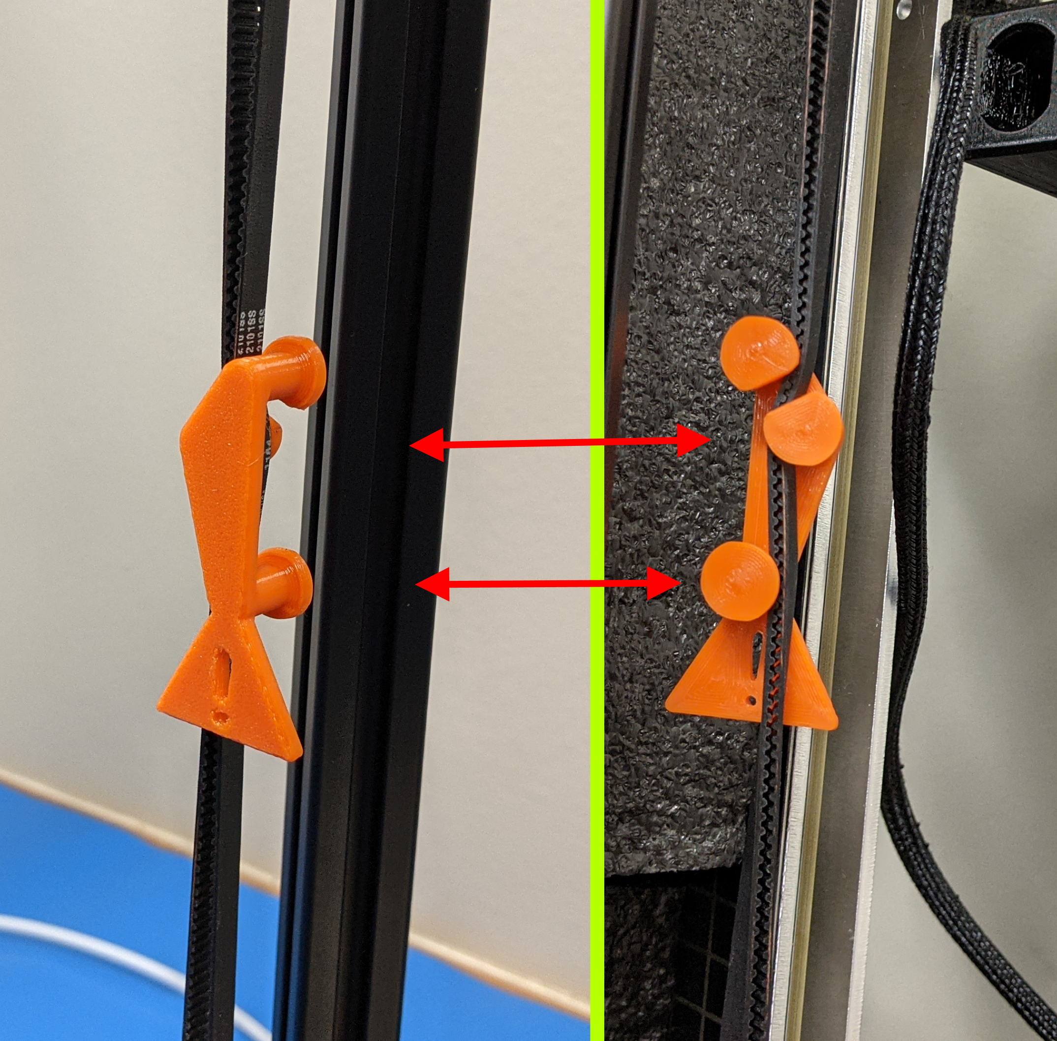
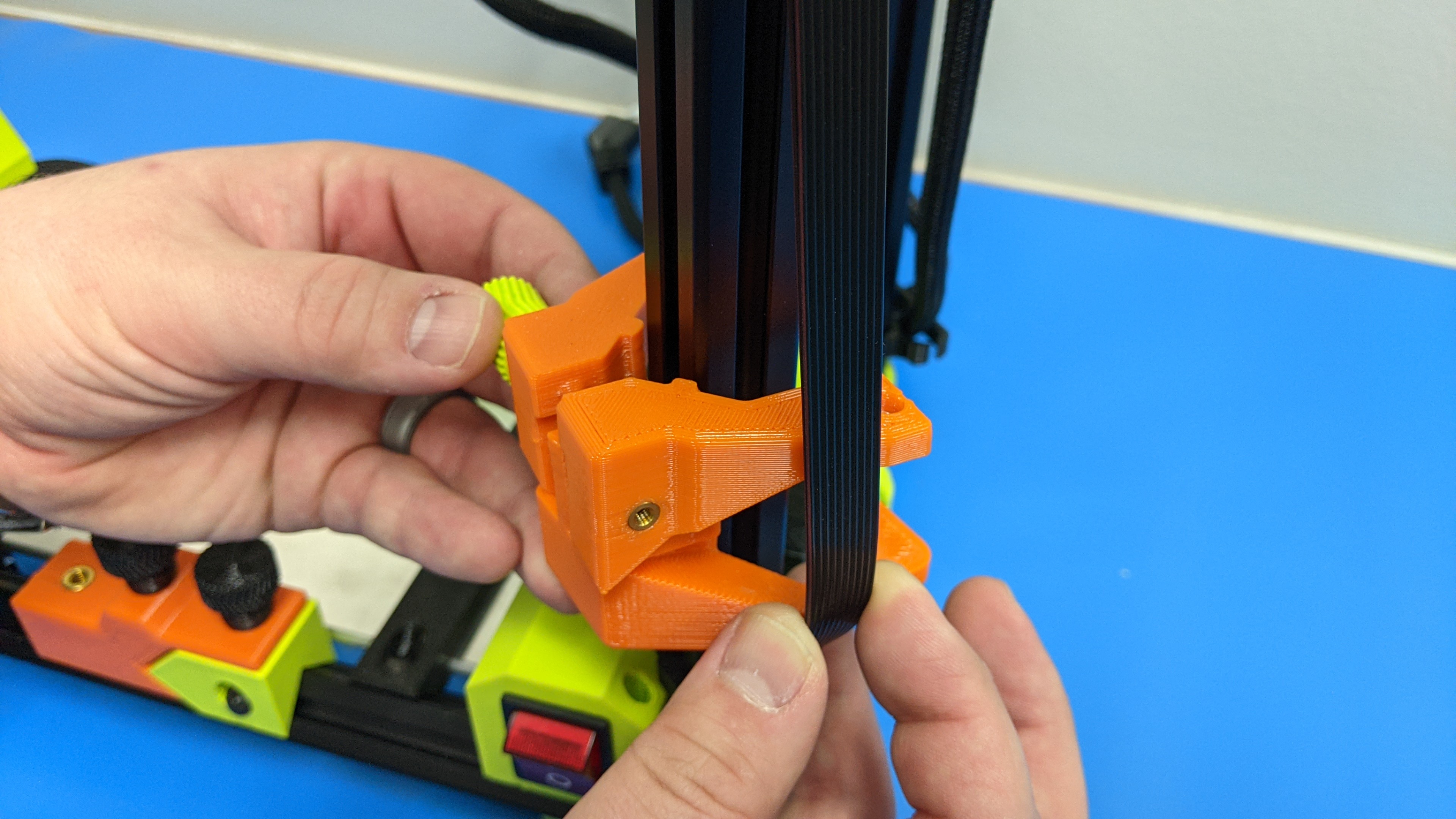
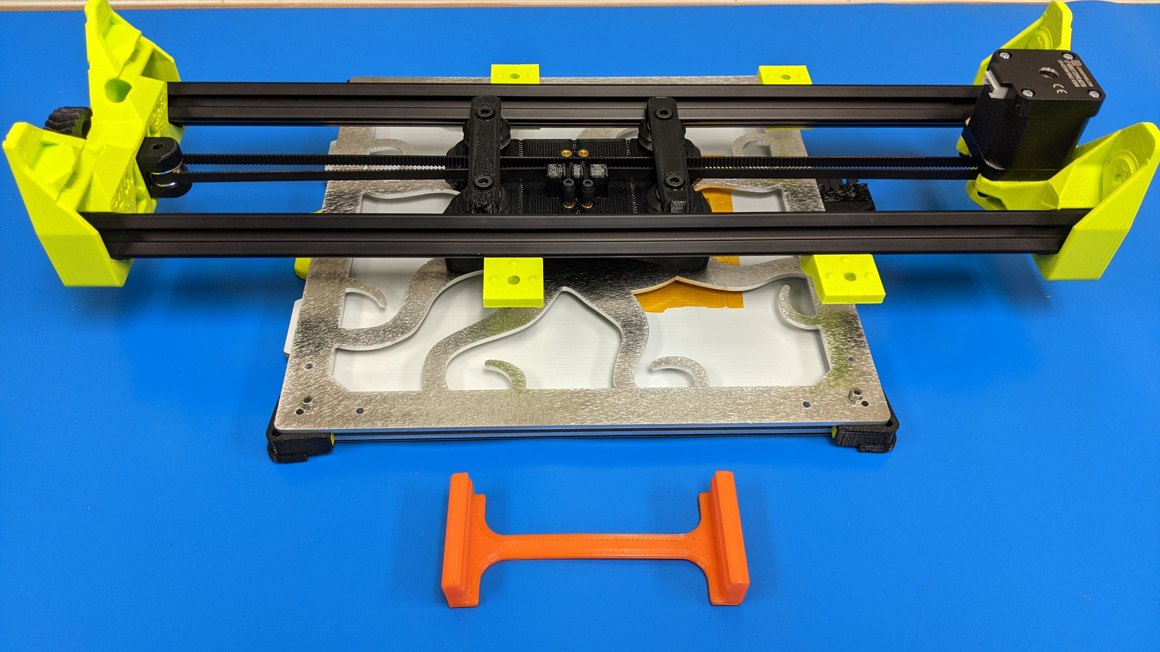
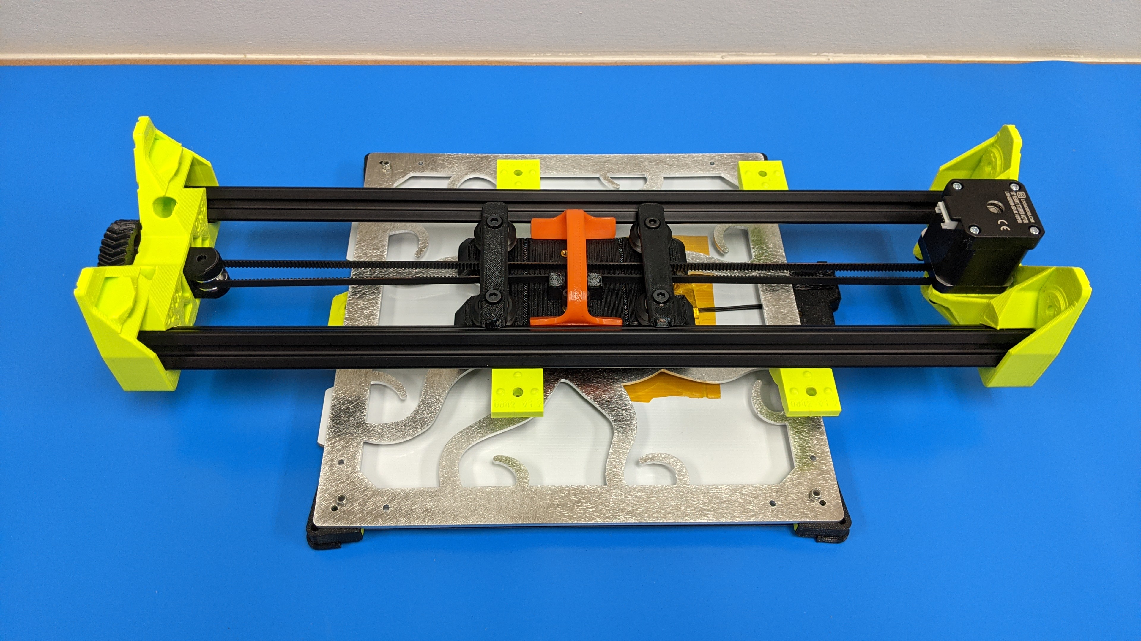
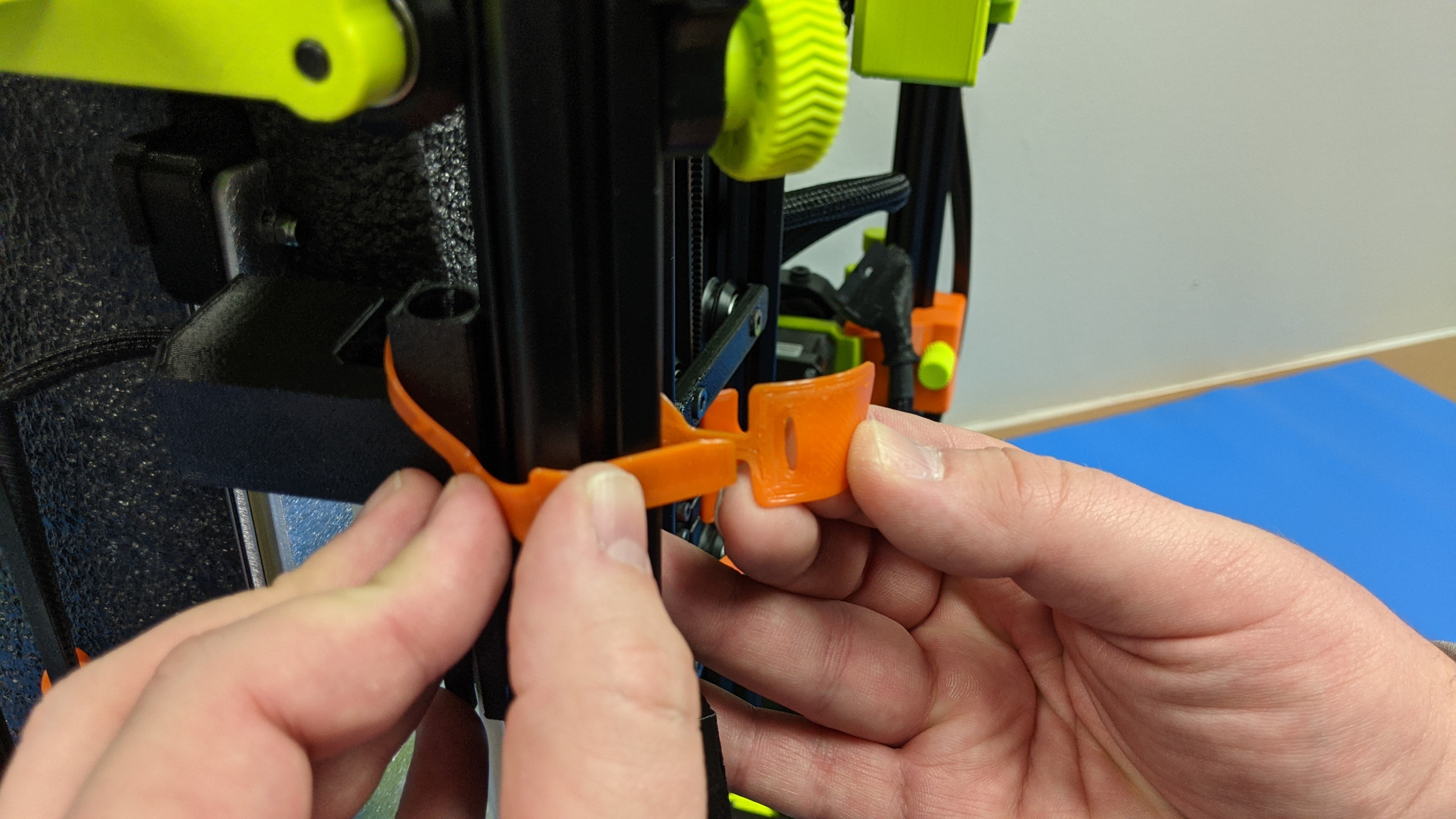
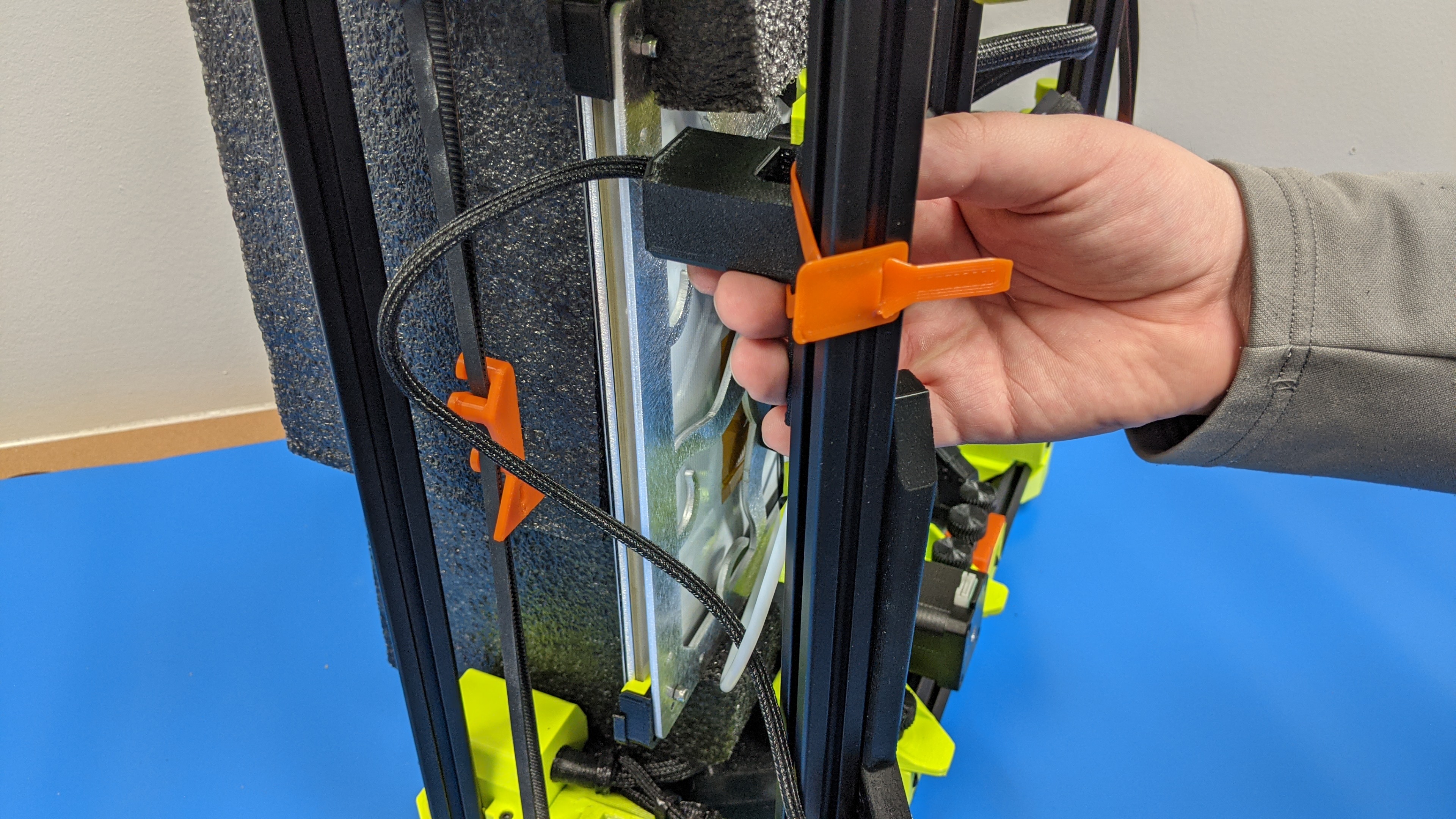
Gather the 3 orange belt clamps and the y-axis mount.
5A
Insert one end of the belt clamp around both sides of a belt.
Rotate the belt clamp and loop the belt through the bottom bar to secure clamp to belt.
Repeat for both left and right z-axis belts.
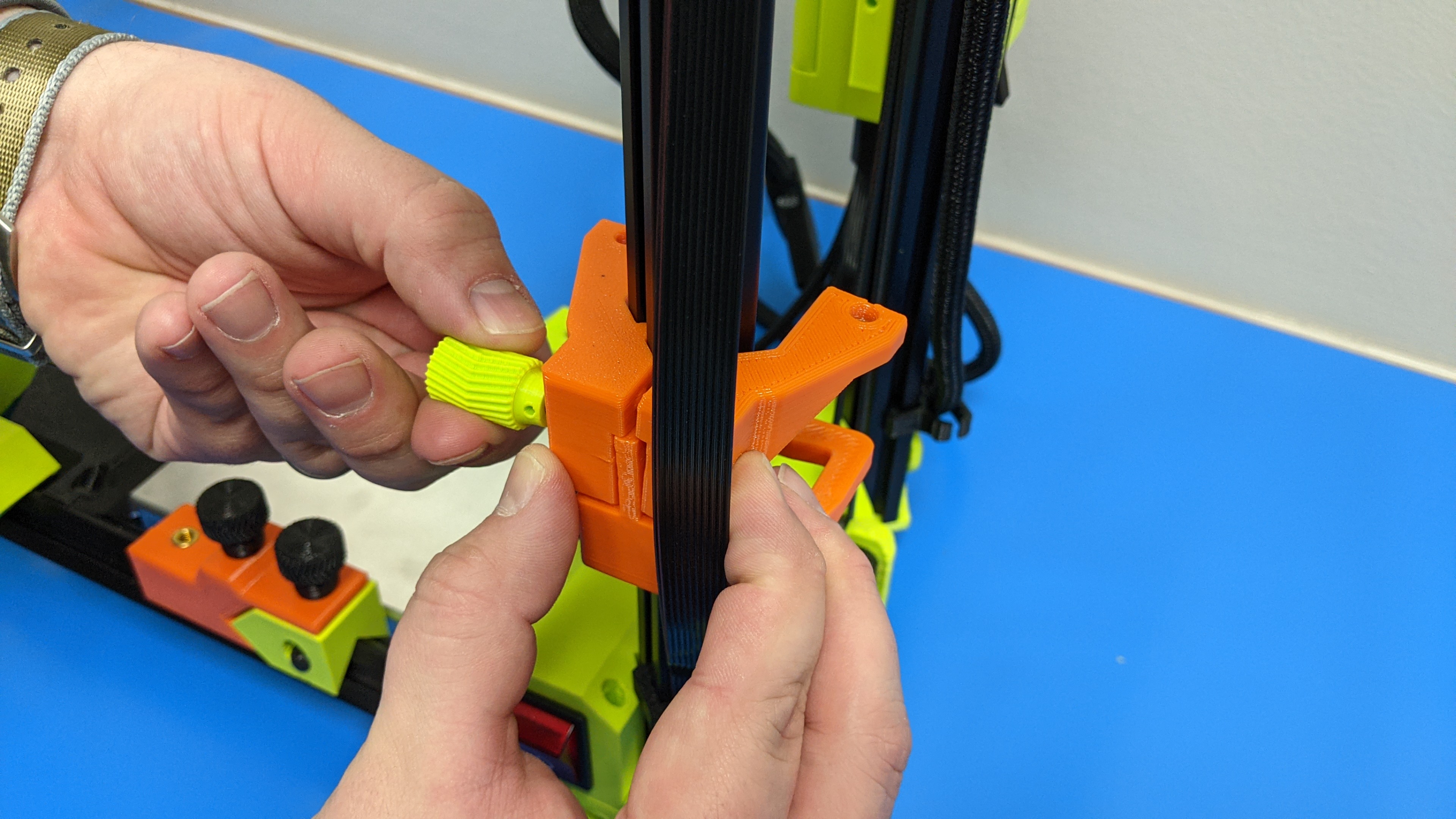
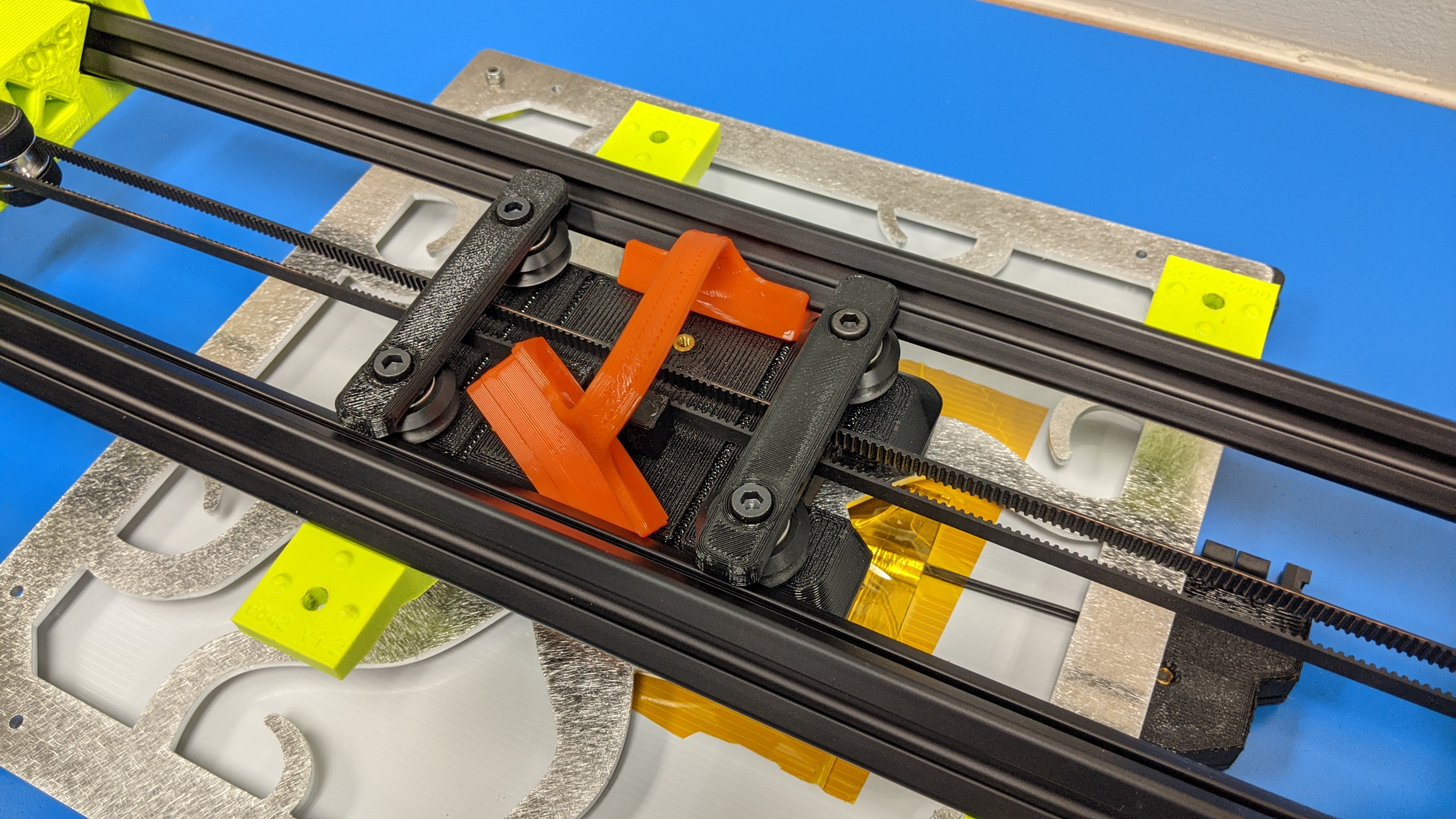
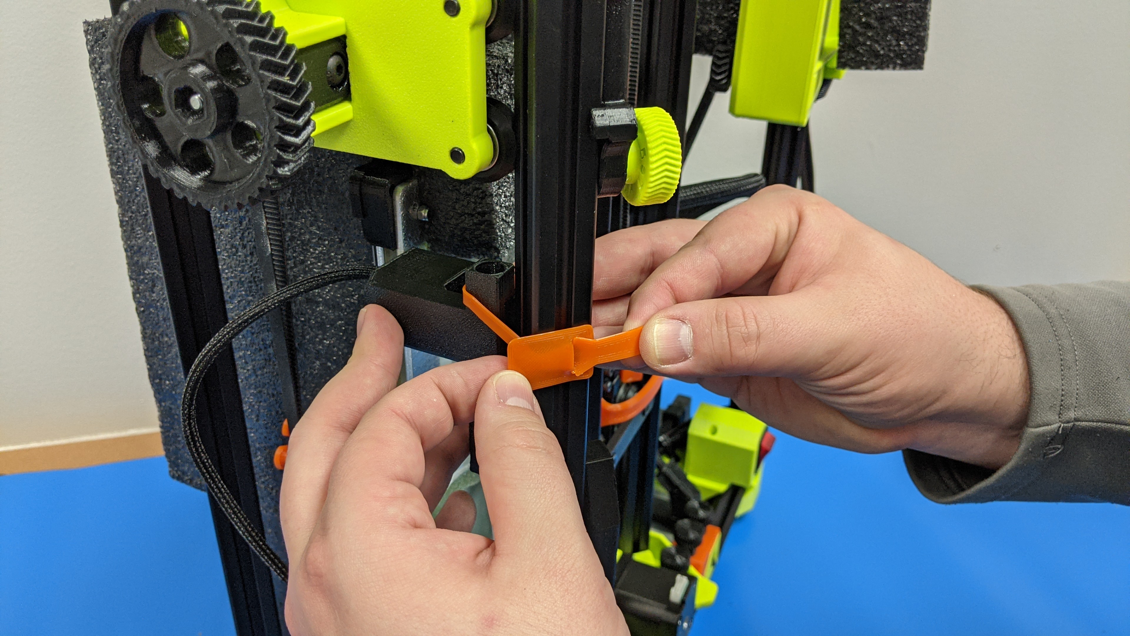
5B
Move tool head x-carriage all the way to the right side of the printer and clamp x-axis belt in place.
5C
Take orange y-axis bed mount and place it on the printer extrusion at the front of the printer and push it down into place.
Move it right until it contacts the right side y-axis mount.
Install two of (4x) y-axis thumb screws into the two right spots to hold the bed mount in place and to secure loose thumb screw in place.


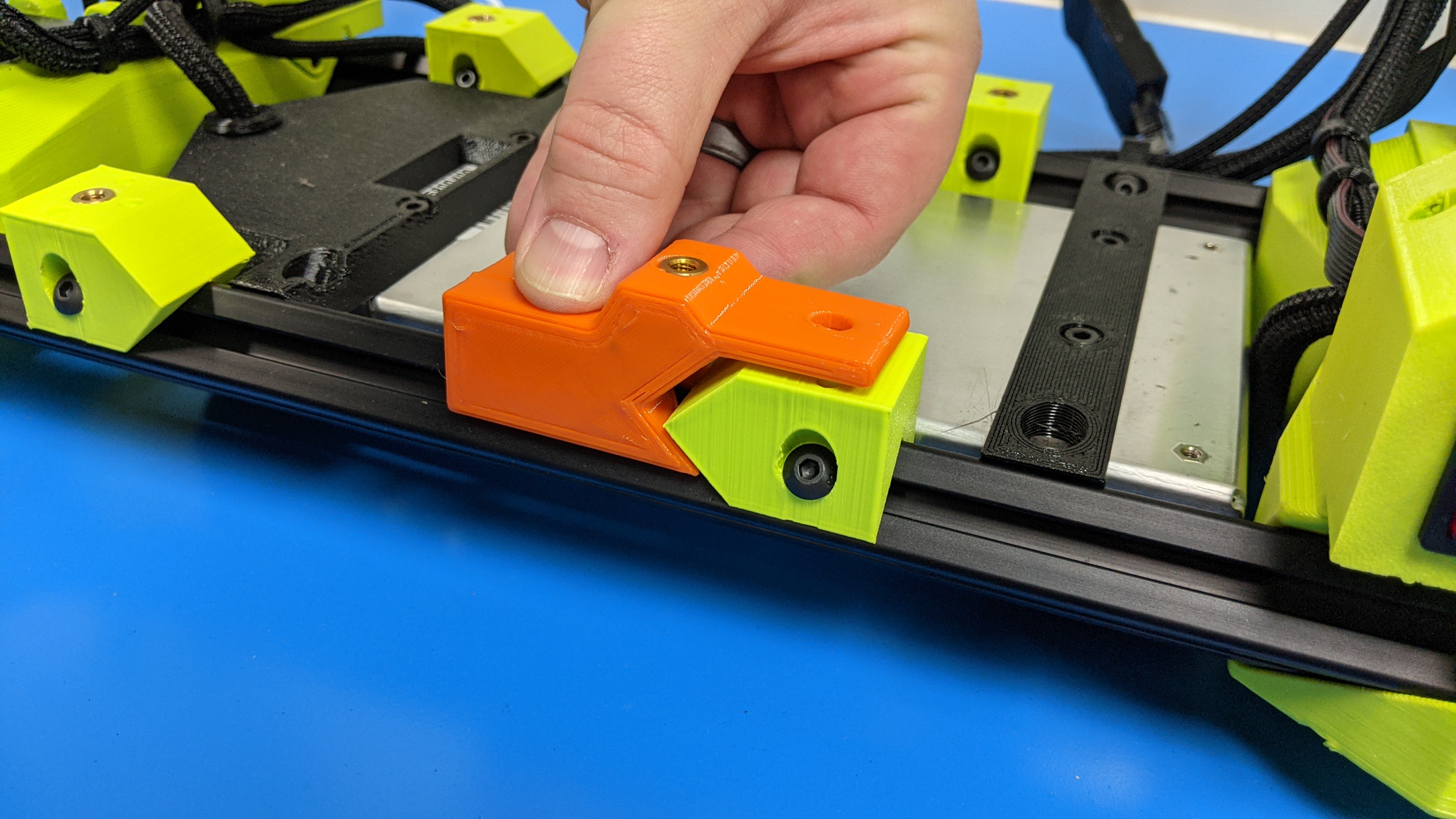

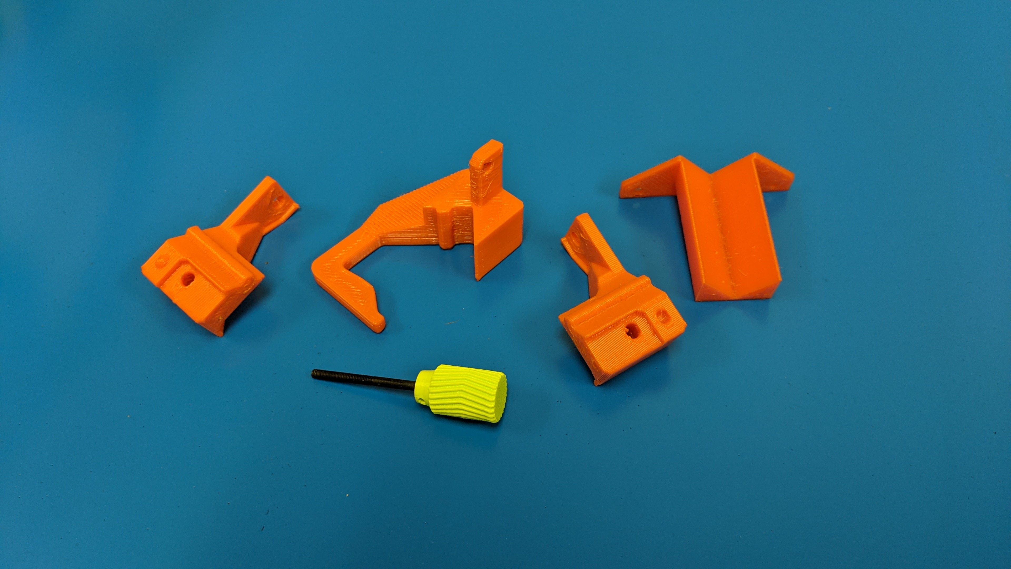
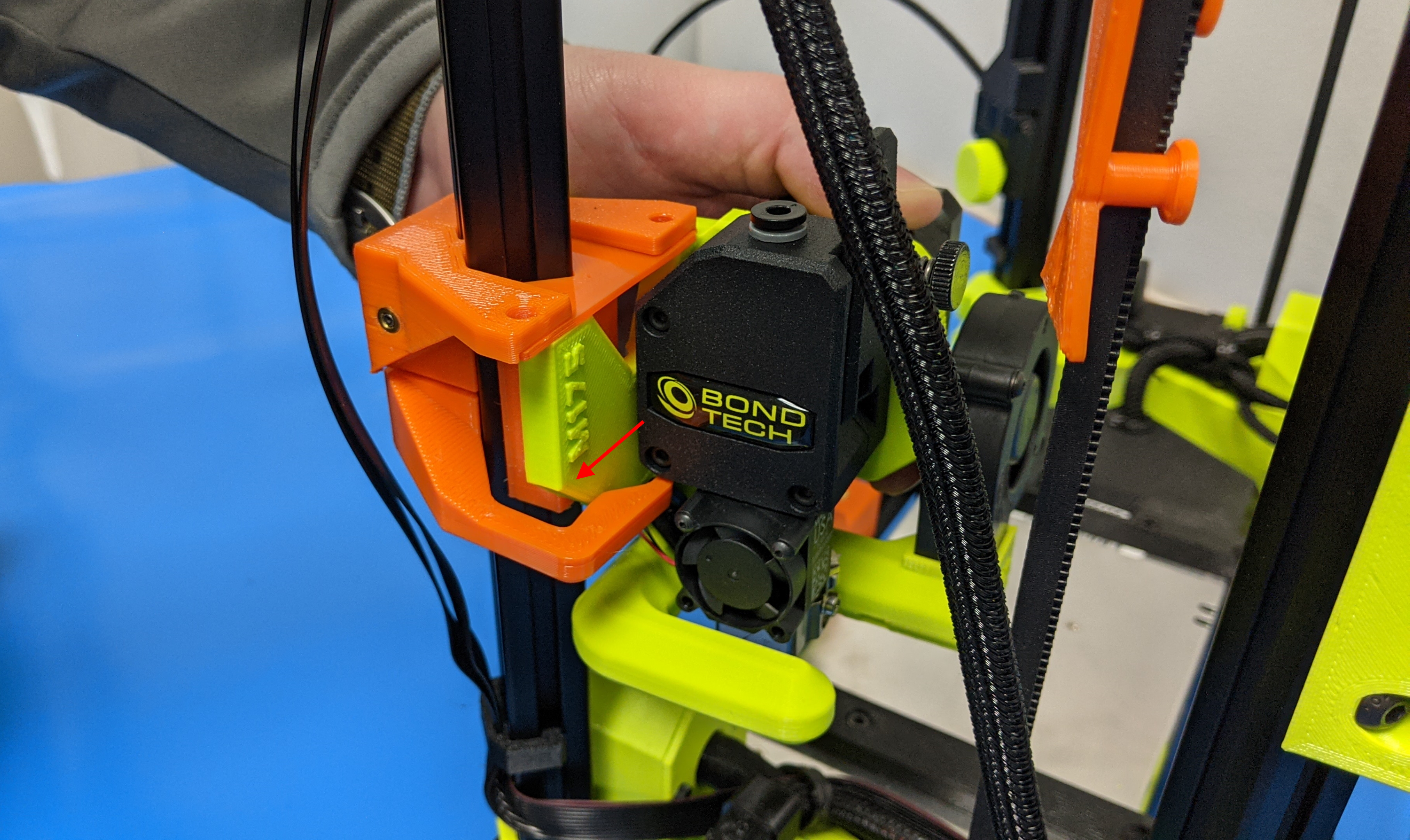
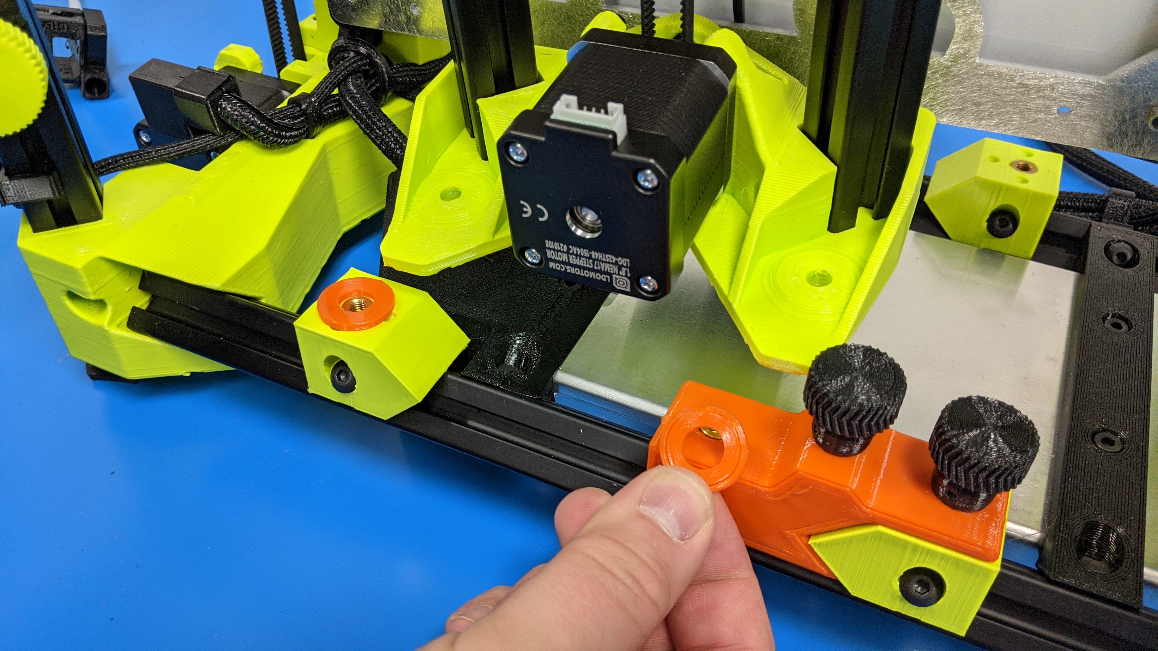
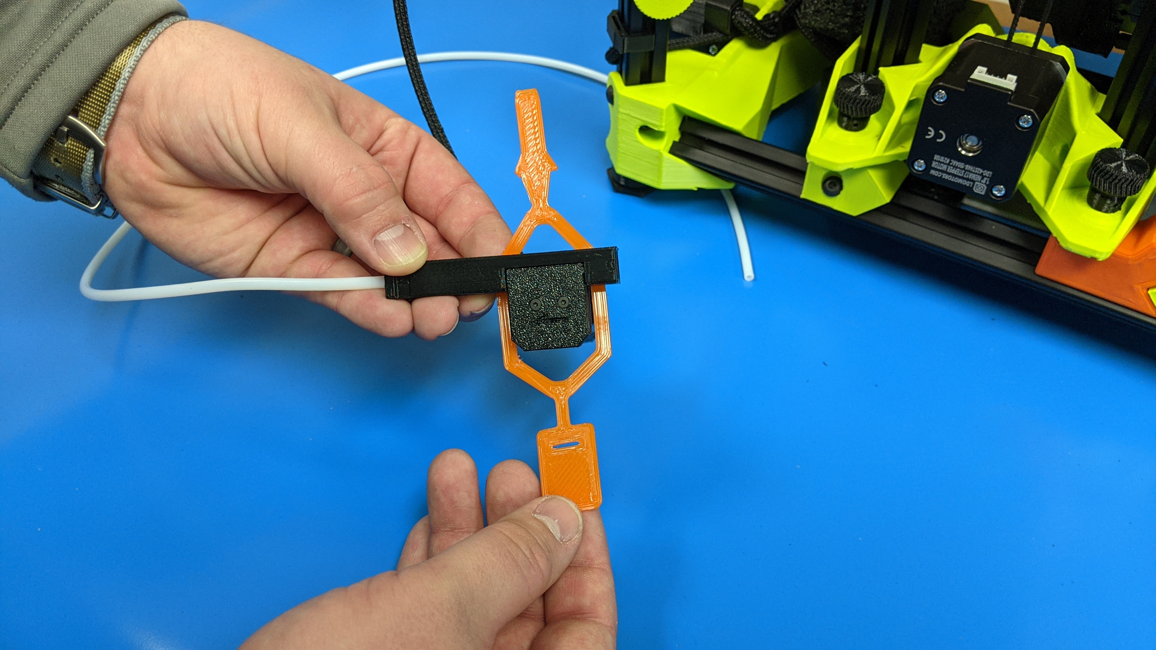
Gather the 4 tool head mounting components and the longer tool head mounting thumb screw.
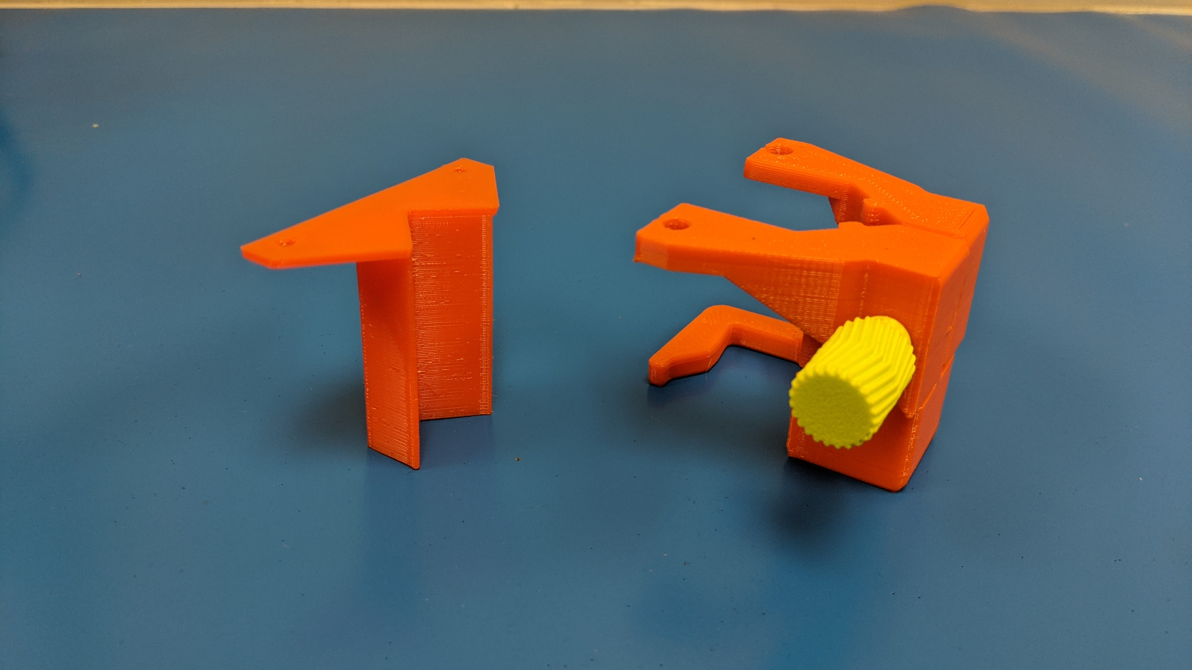
6A Partially assemble the tool head mount by using the 3 rigid parts and the thumb screw to hold them together.
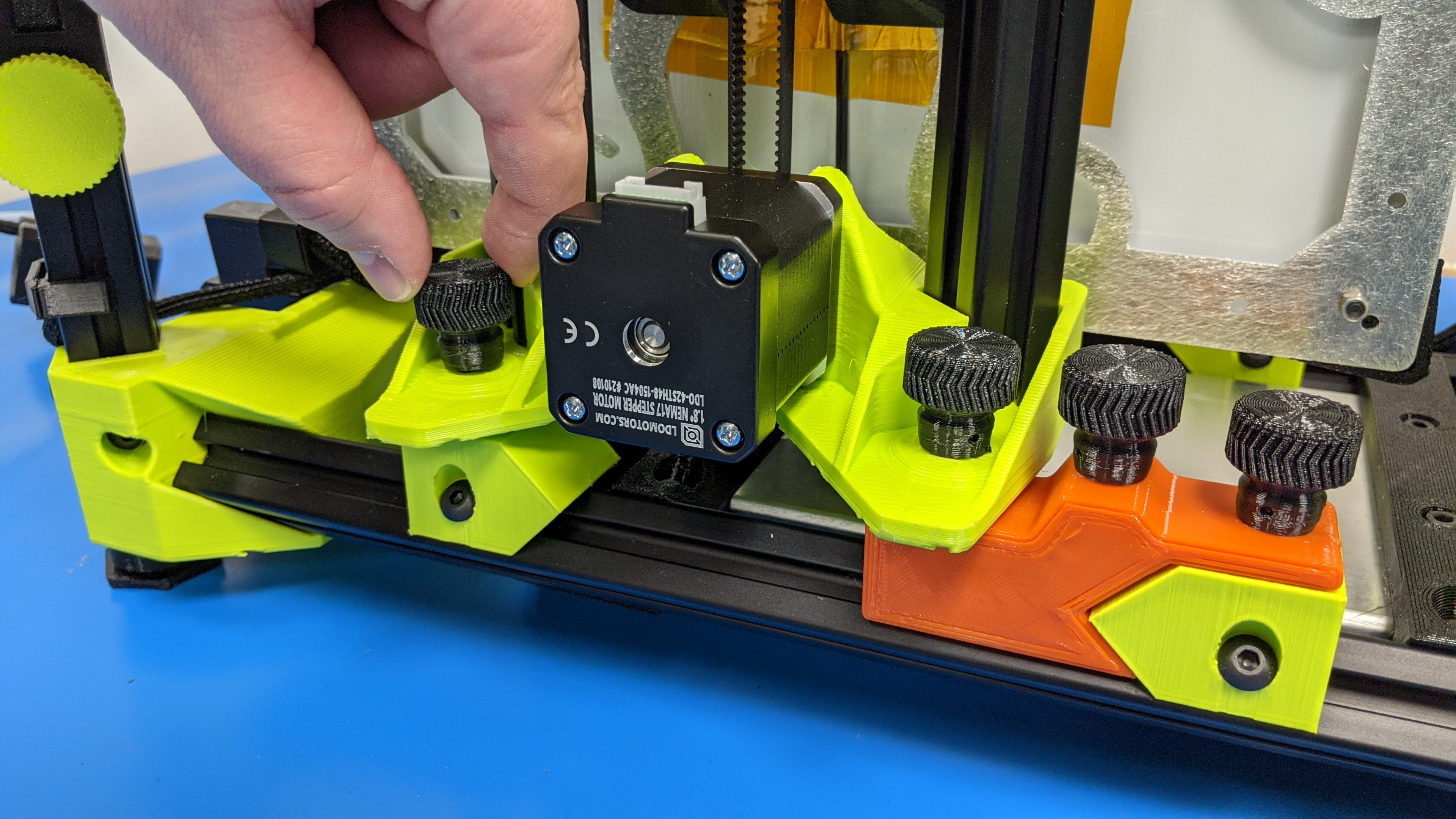
6B
Slide the mount to the front right extrusion, being sure to mount it under the LCD cables.
Tighten down the thumb screw to secure it into position.
It should be mount roughly half way up the extrusion.
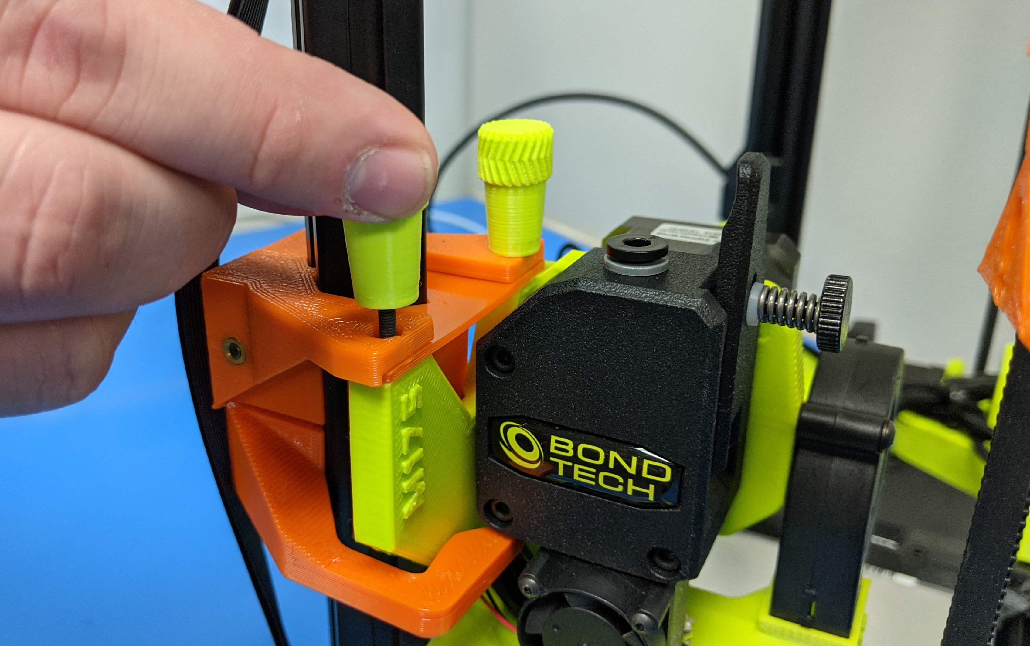
6C
Place flexible orange mount on other side of the tool head mount.
6D
Slide tool head into position on the mount.
6E
Secure tool head to the mount using the two tool head mount screws.

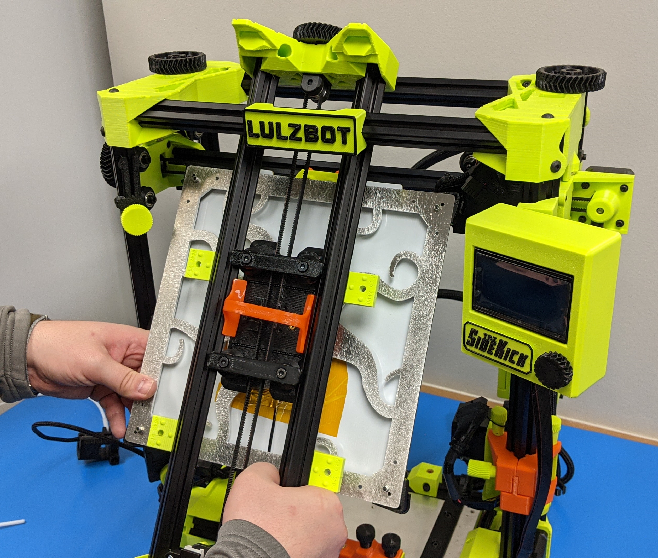
The y-axis bed will need to be secured before mounting the y-axis inside the printers frame. Locate the orange flexible y-axis shipping wedge.
7A
Insert the flexible wedge into the y-axis between the bearings to secure the bed into position.
This will help secure the bed and prevent movement while in transit.
7B
Locate the remaining two y-axis thumb screws and the two orange O-rings.
7C
Slide the idler side of the y-axis into the printers frame between the front extrusion and the x-axis rail.
The bed should face the back side of the printer.
7D
Place the two O-rings on the bottom two open inserts and secure the y-axis to the printer frame using the two thumb screws.
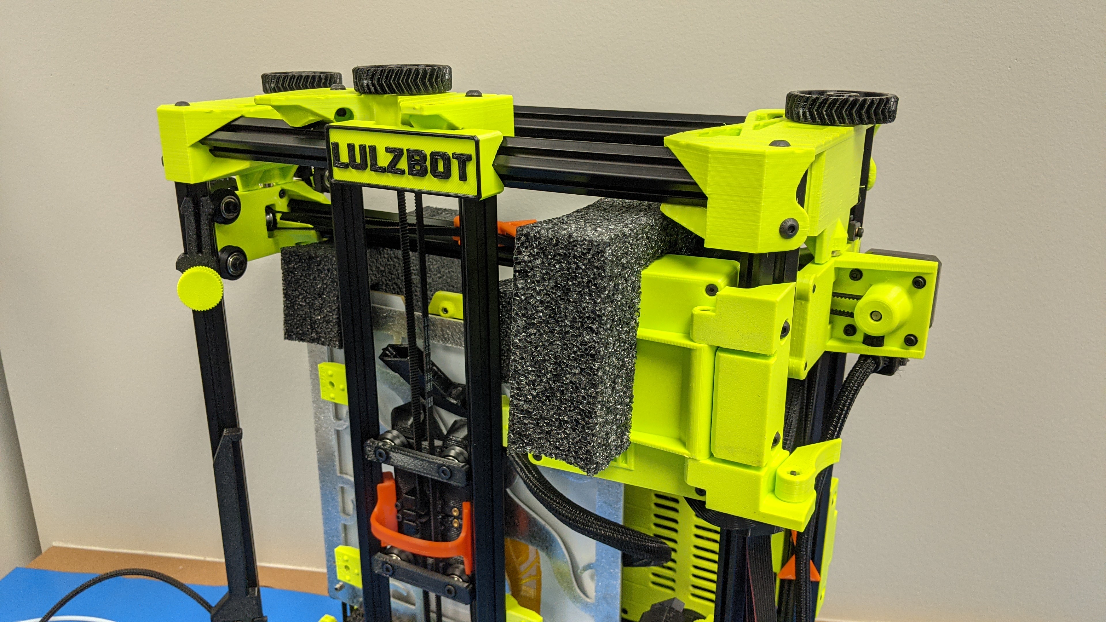
8A
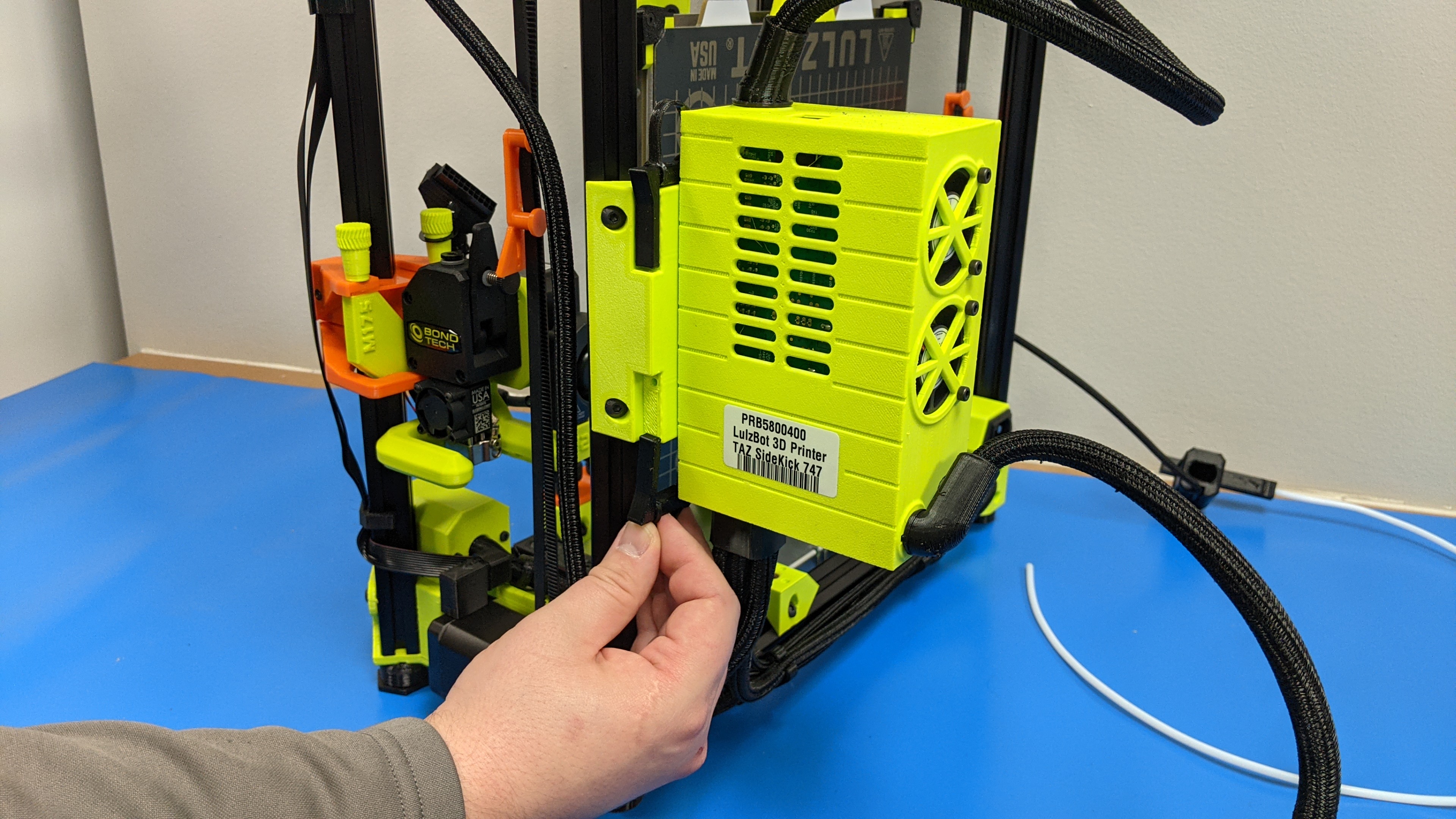
Remove the two clips holding the control box in position.
Flip the box inwards and secure with the same clips
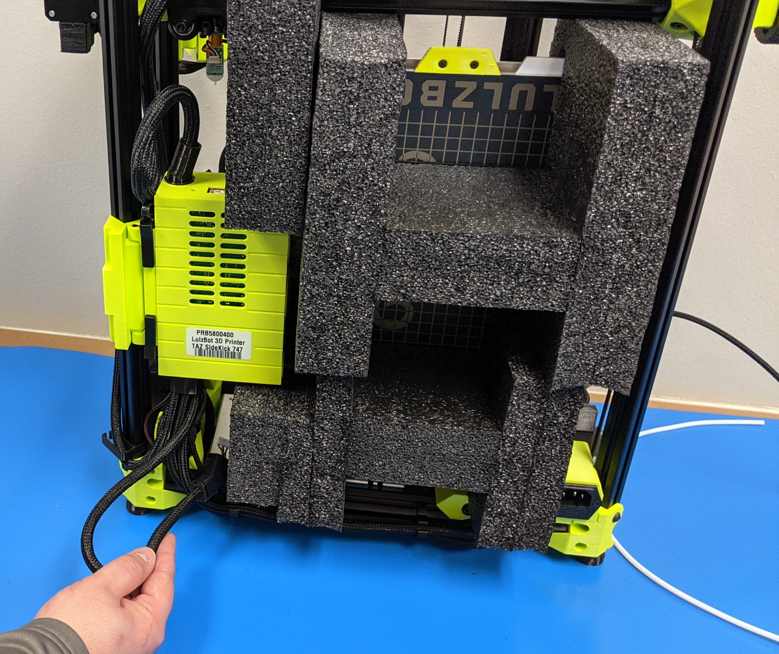
8B
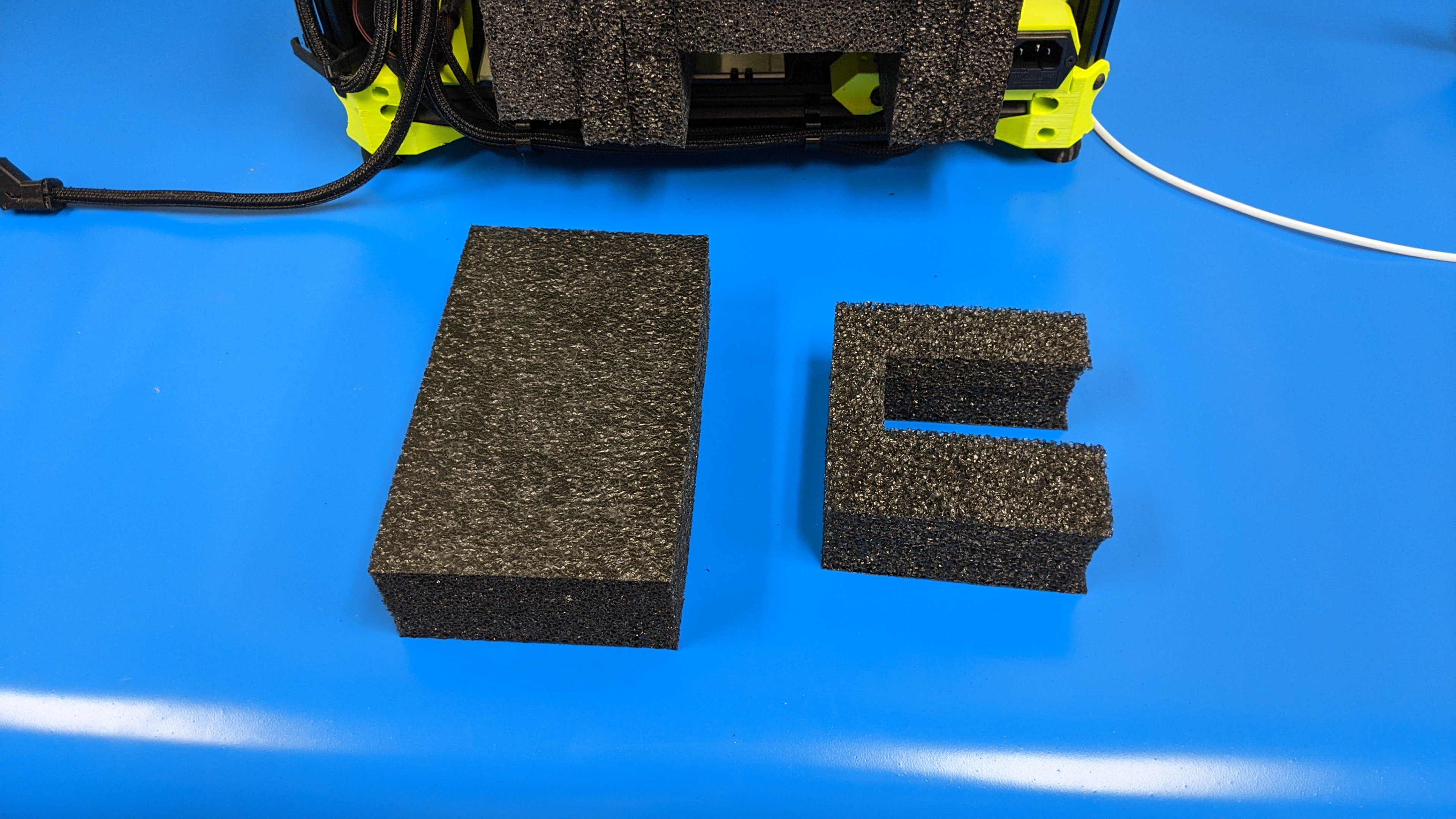
Gather internal y-axis foam.
8C
Insert the top y-axis foam into place ensure that the foam fits on the top of the bed.
8D
Slide the bottom foam piece into position and ensure that it is holding the bed in place and preventing it from coming down and contacting the bottom of the printer frame.
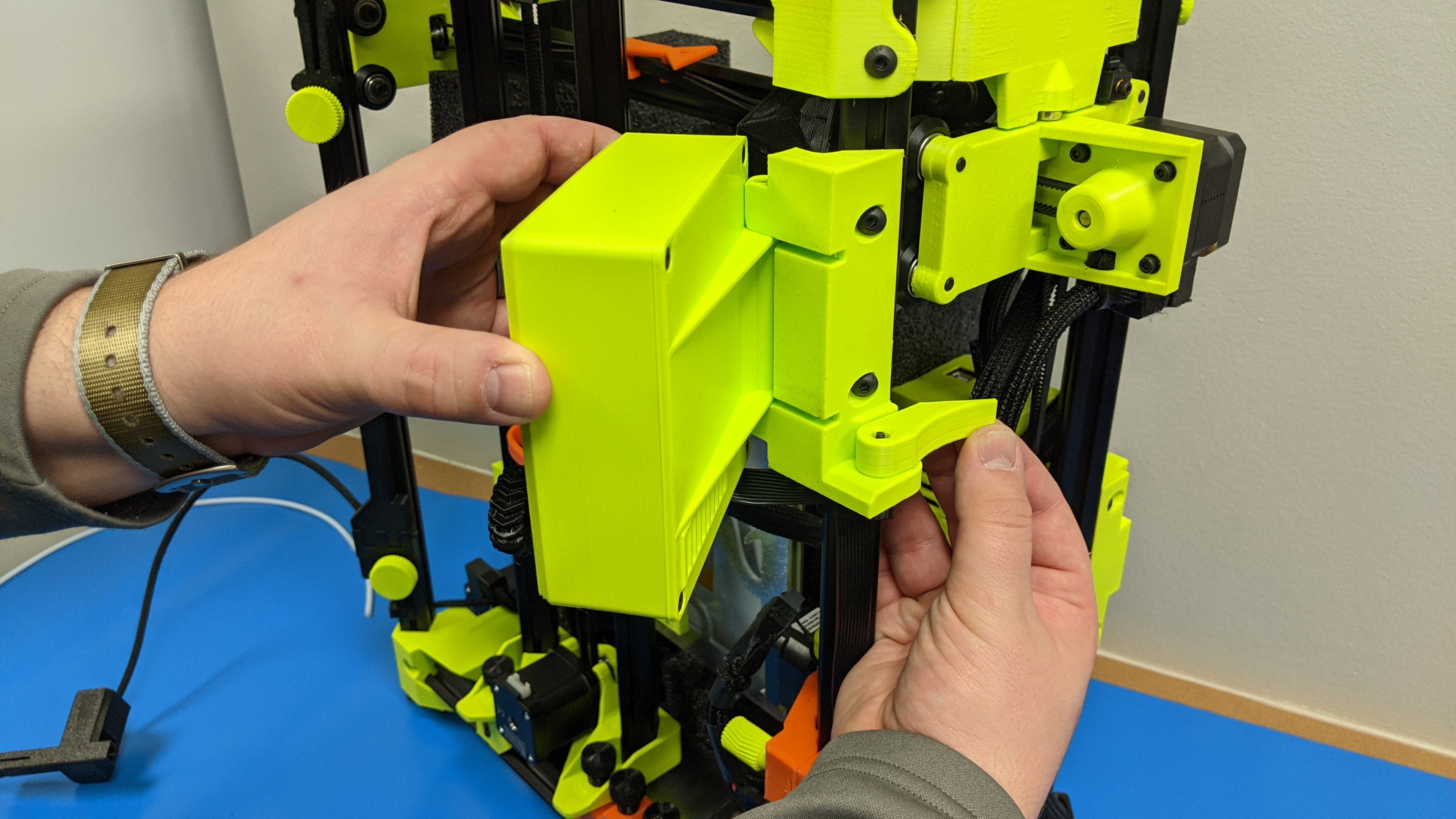
8E
Gather LCD foam and control box foam (Only the 747 will use the control box foam).
8F
Move the LCD support arm all the way back and install the foam over the LCD.
Rotate the LCD inwards into the printer frame.
8G (SideKick 747 only)
Place control box foam into position above control box.
8H
Tuck in cables and harnesses for the y-axis


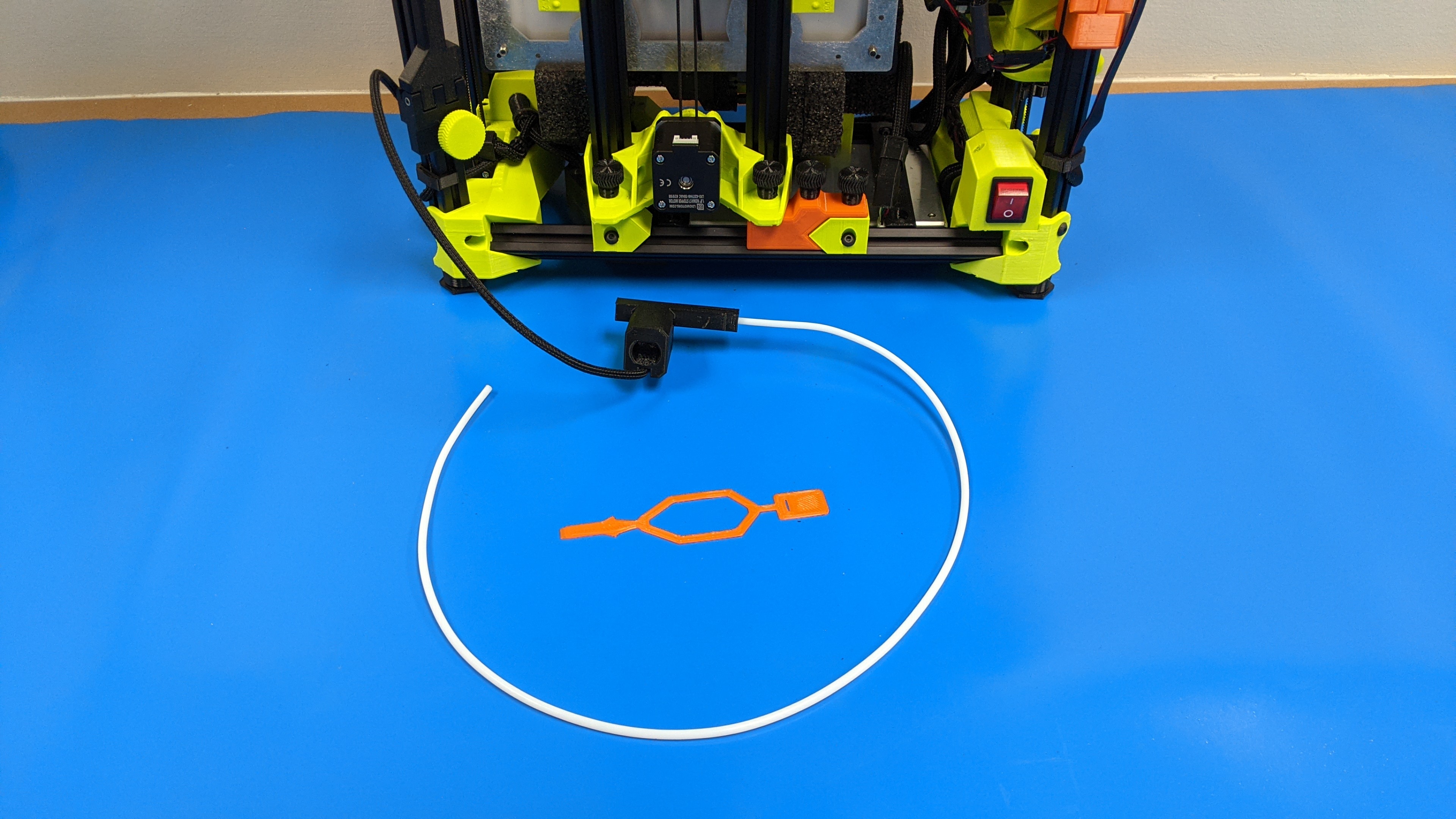
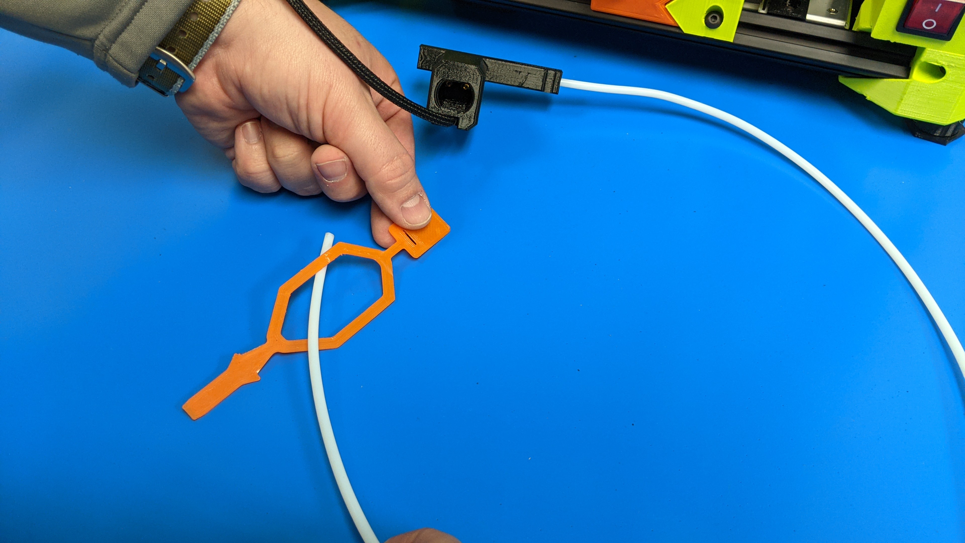
If your SideKick came with a runout sensor, it will need to be mounted to the printers frame.
9A
Insert filament guide into the flexible orange mount and secure around the runout sensor.
9B
Position the runout sensor with the guide tube facing down.
Wrap the flexible strap around the front left extrusion.
Slide the small end into the slot and pull through to secure the sensor to the printer extrusion.
9C
Move sensor into a more internal position.

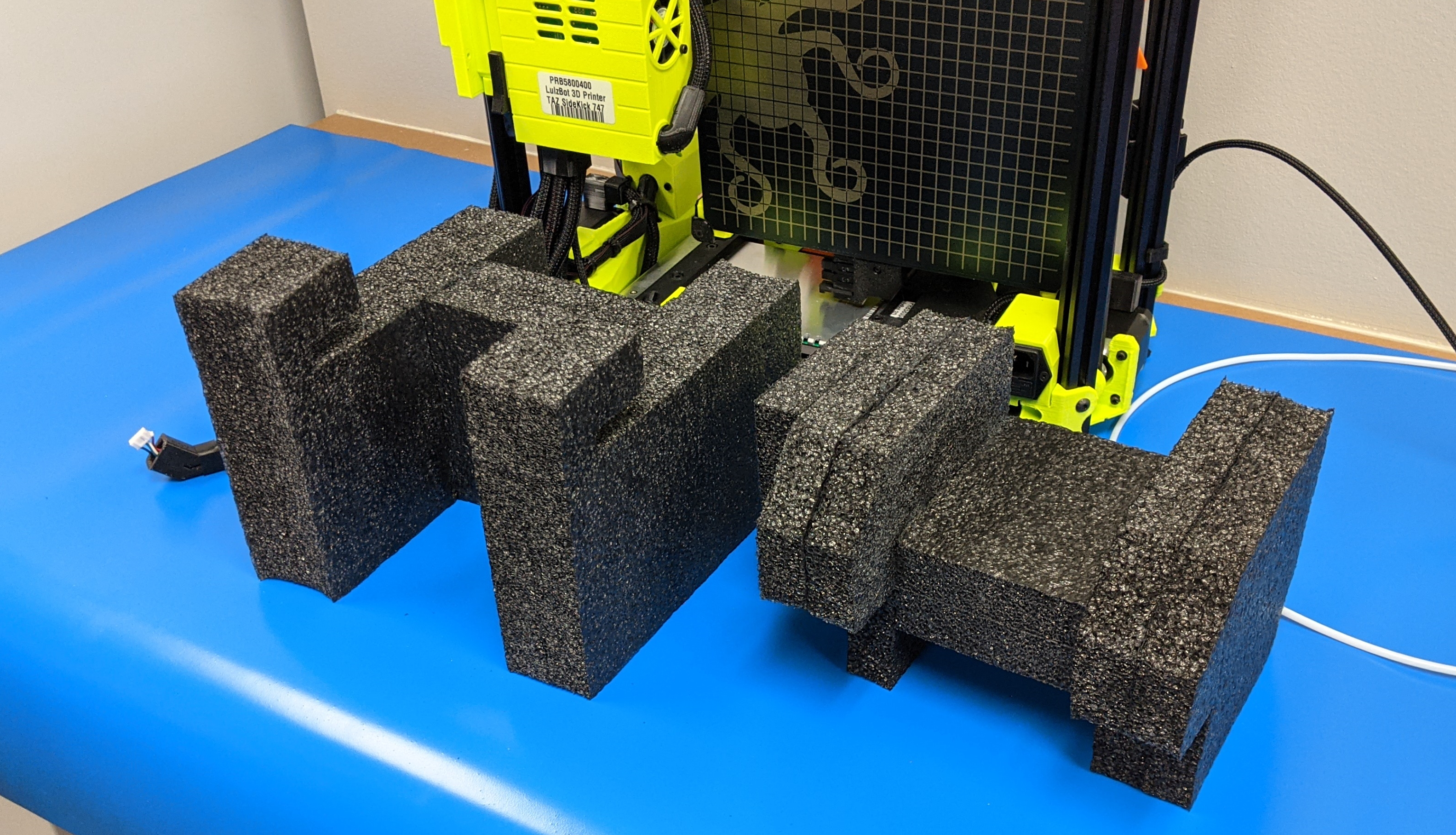
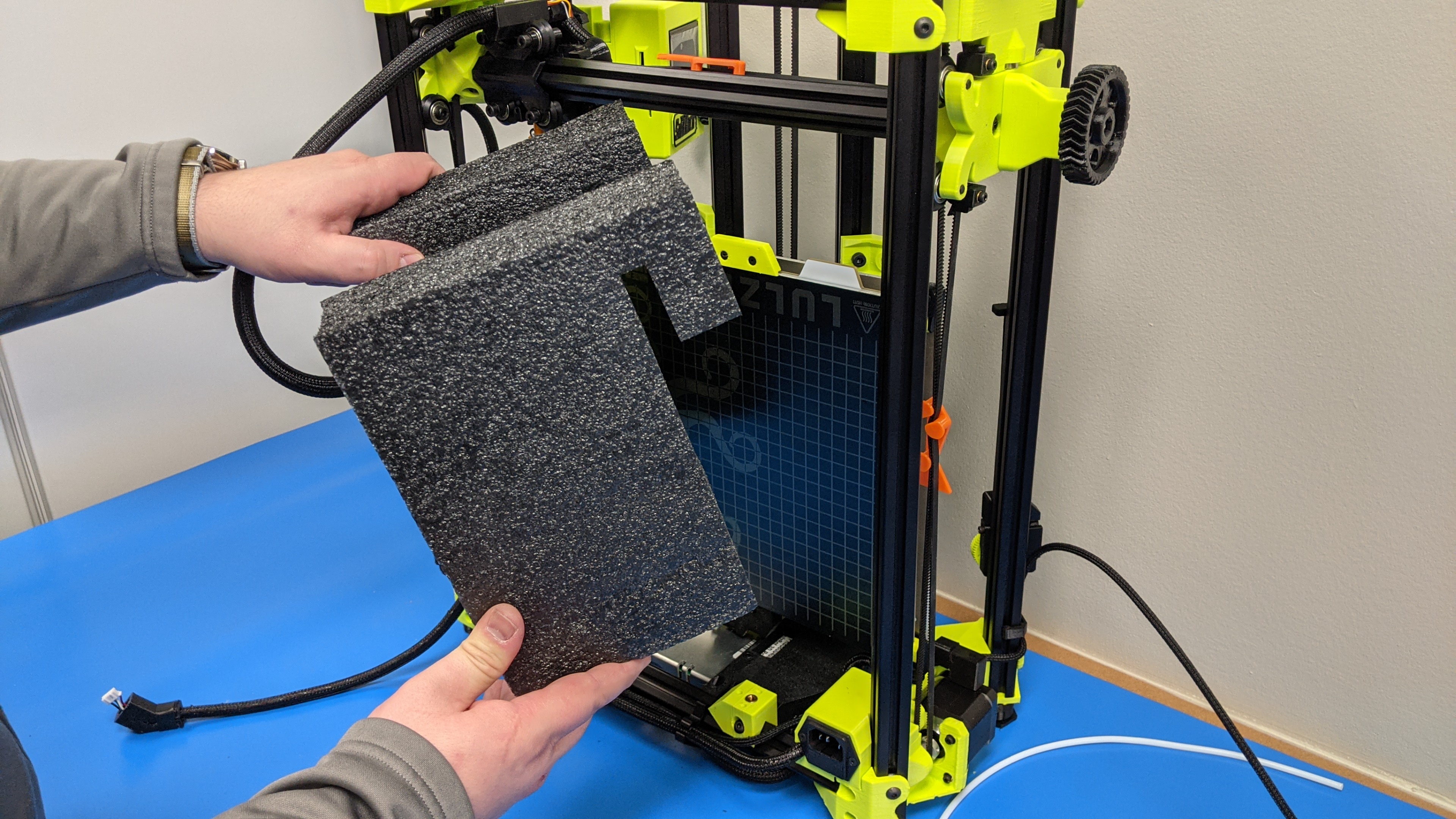
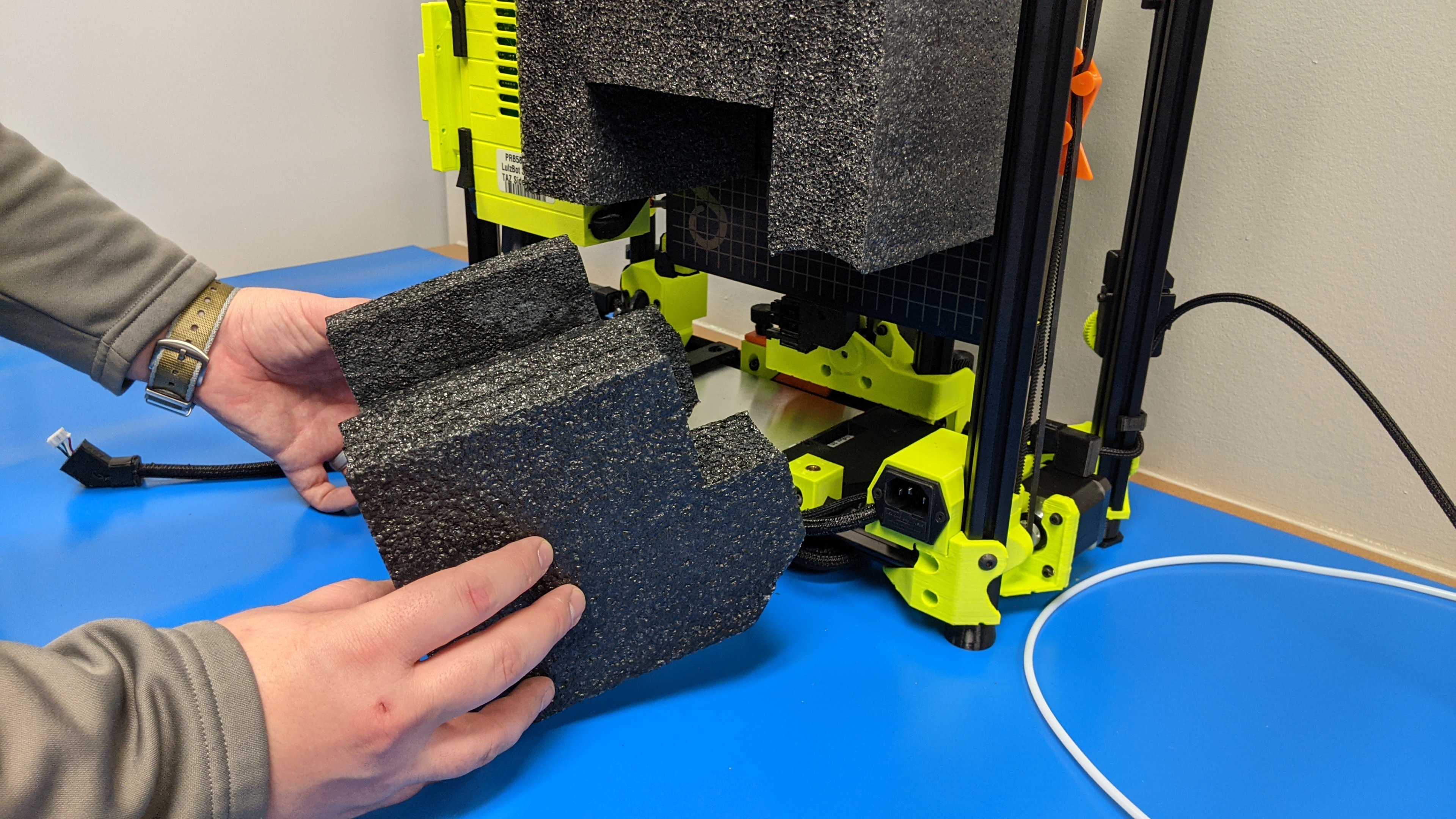
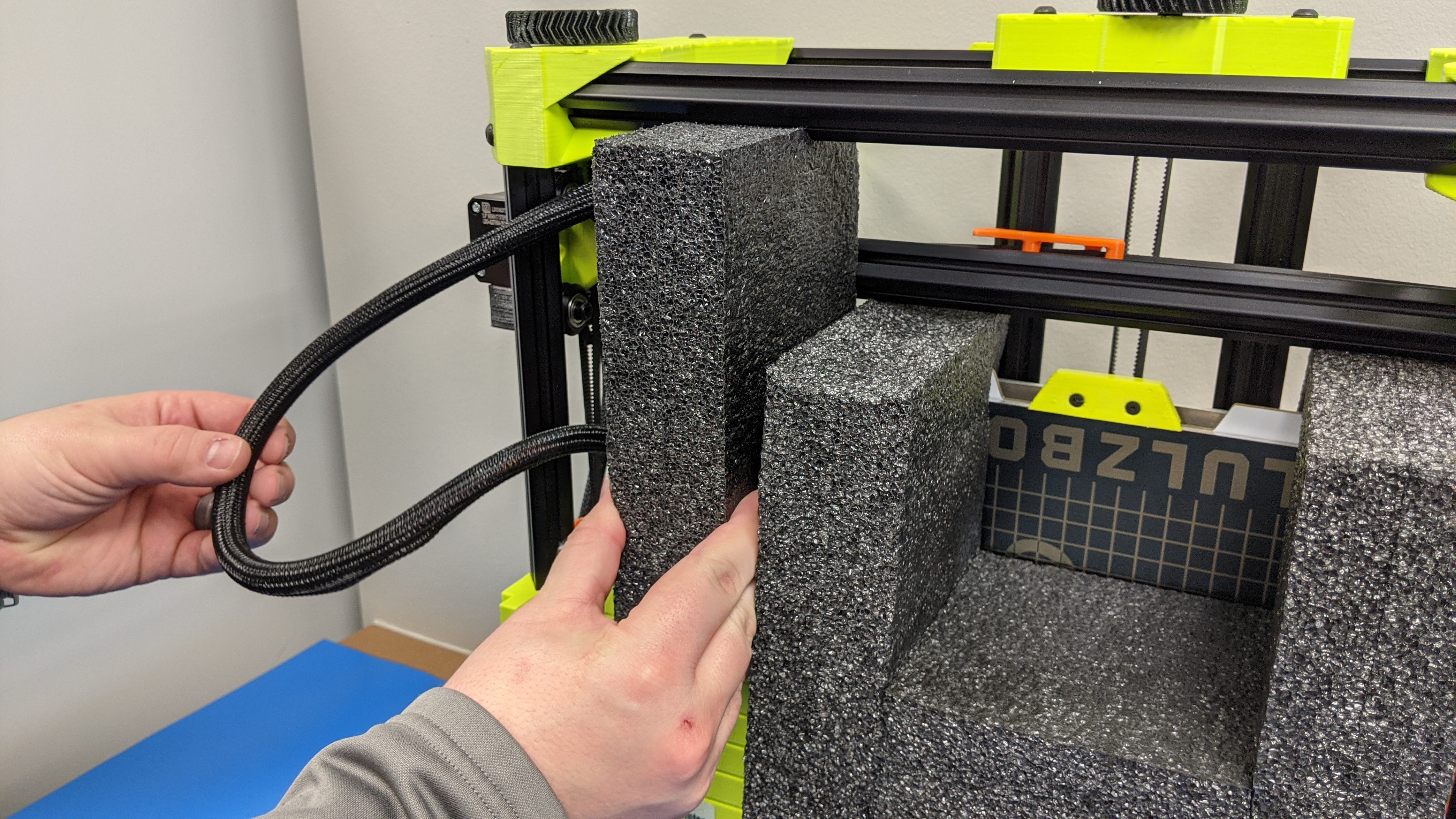
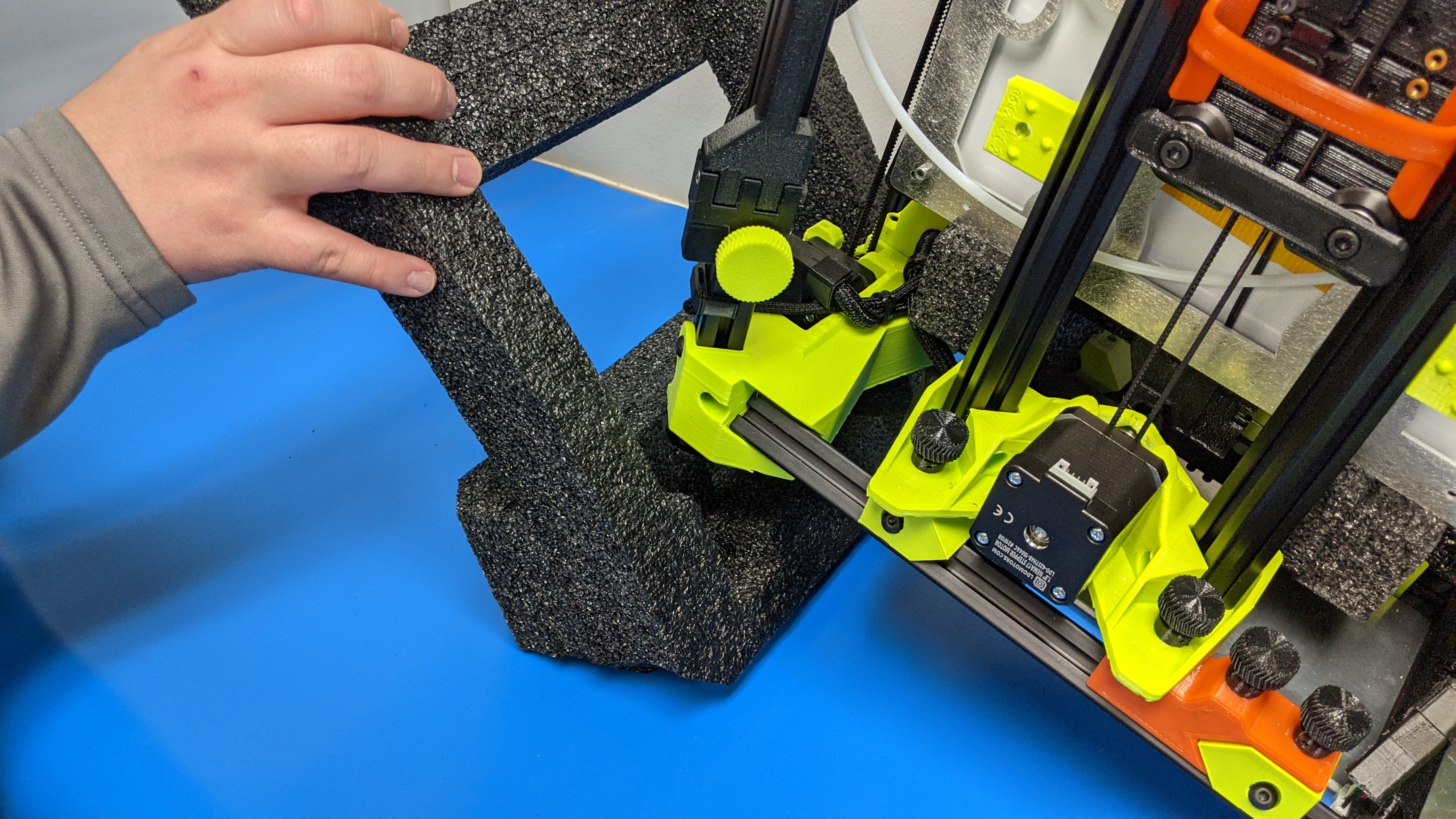
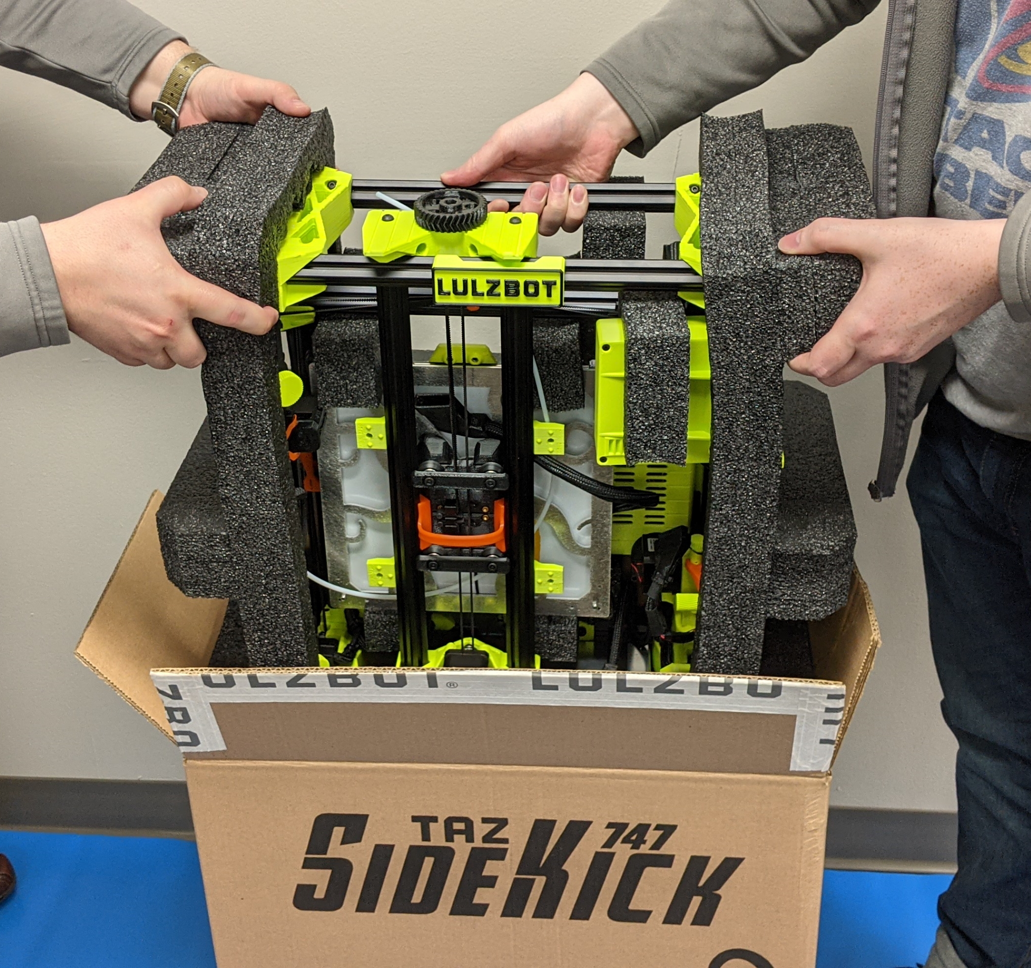
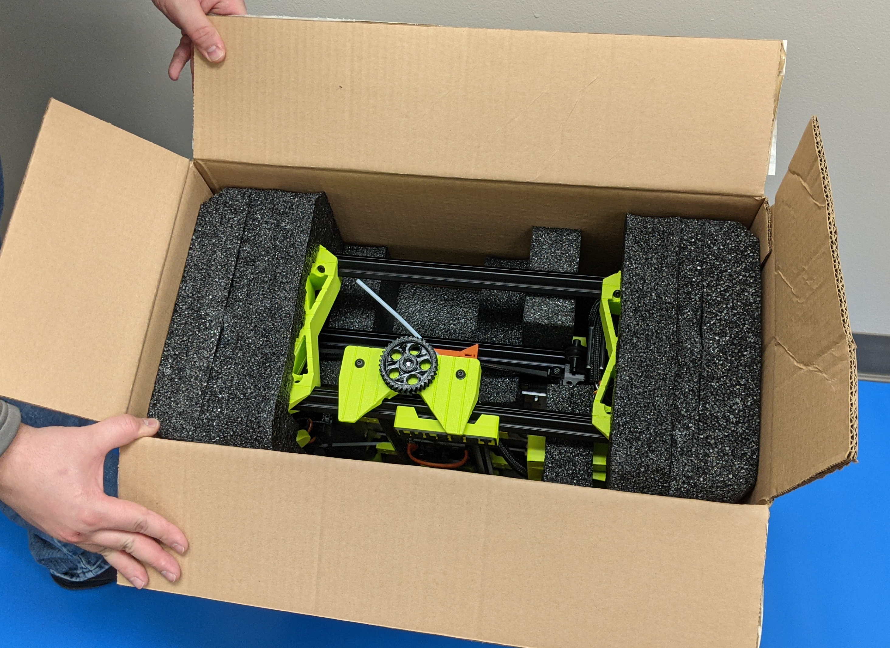
Locate two side foam pieces for final foam installation. The foam pieces are mirrored so there is no left or right piece.
10A
Lift a side of the printer and place the legs into the foam.
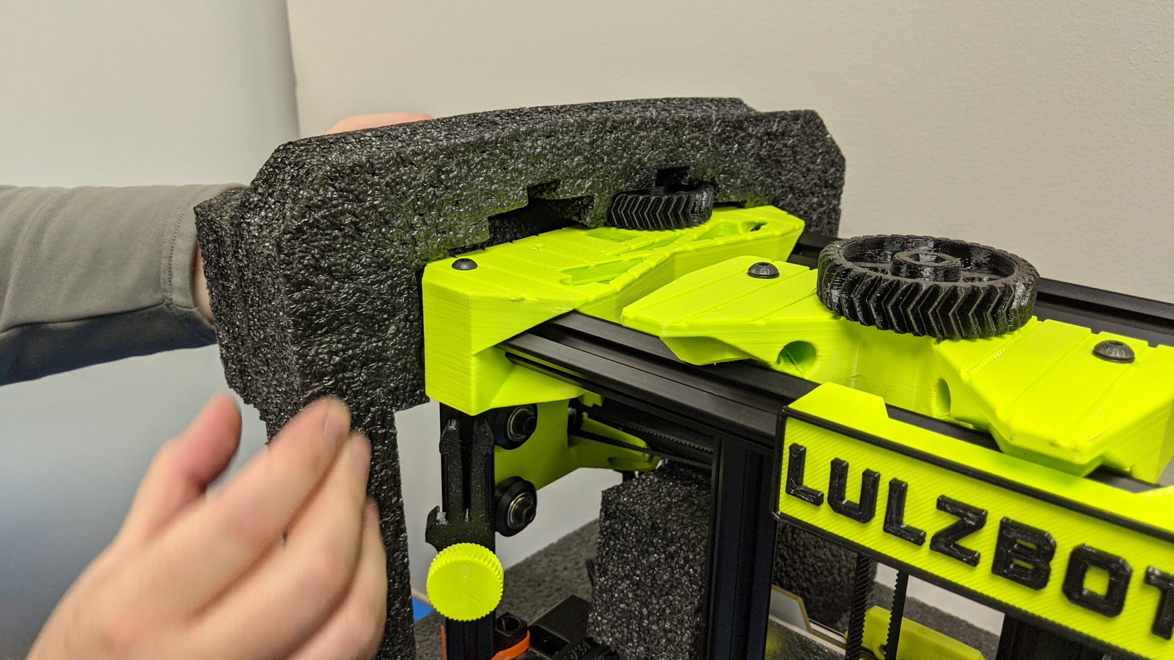
10B
Secure the top of the foam into position over the idler tensioner.
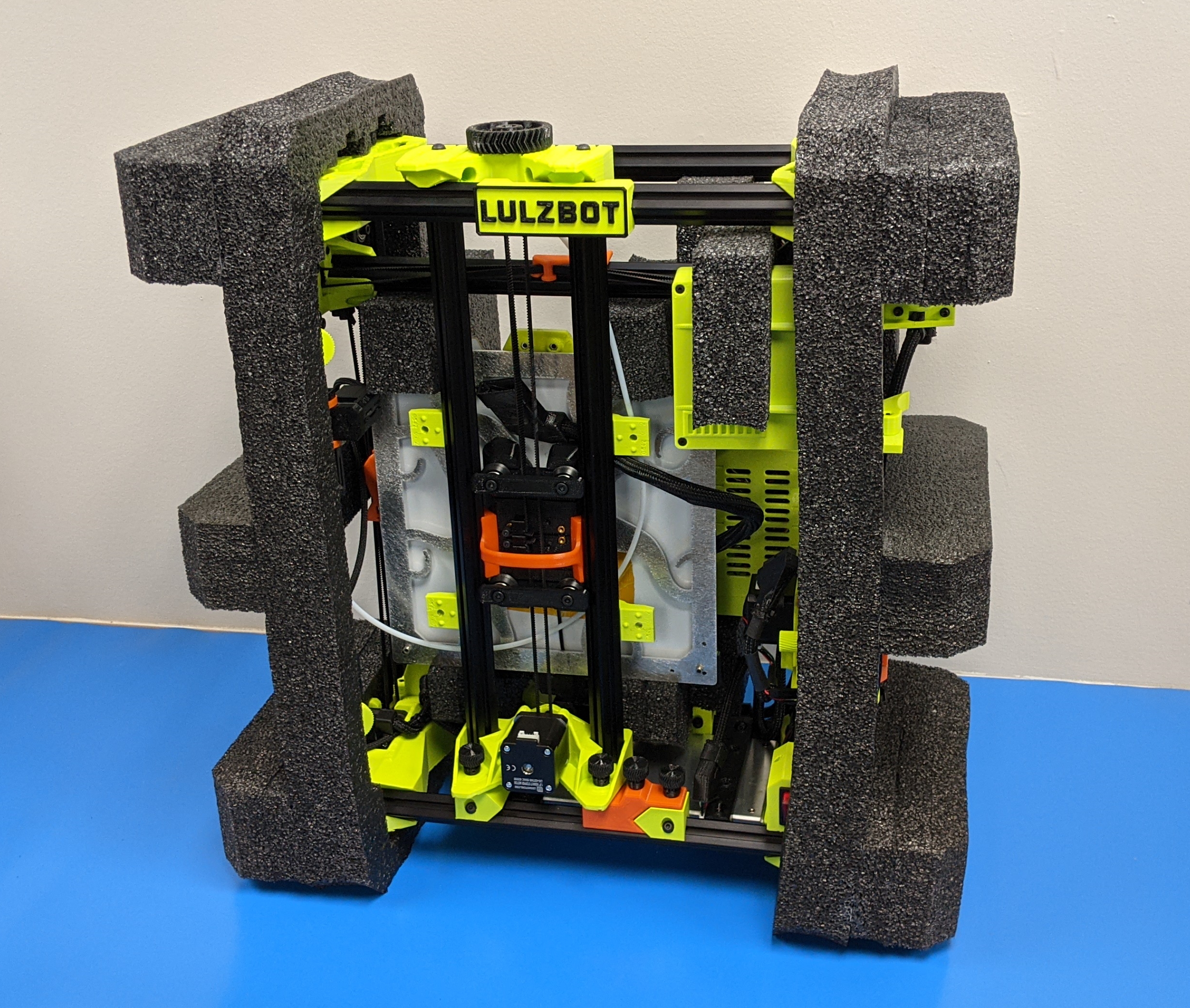
10C
Ensure the side foam is sitting flush against the frame.
10D
Repeat process for other side of printer.
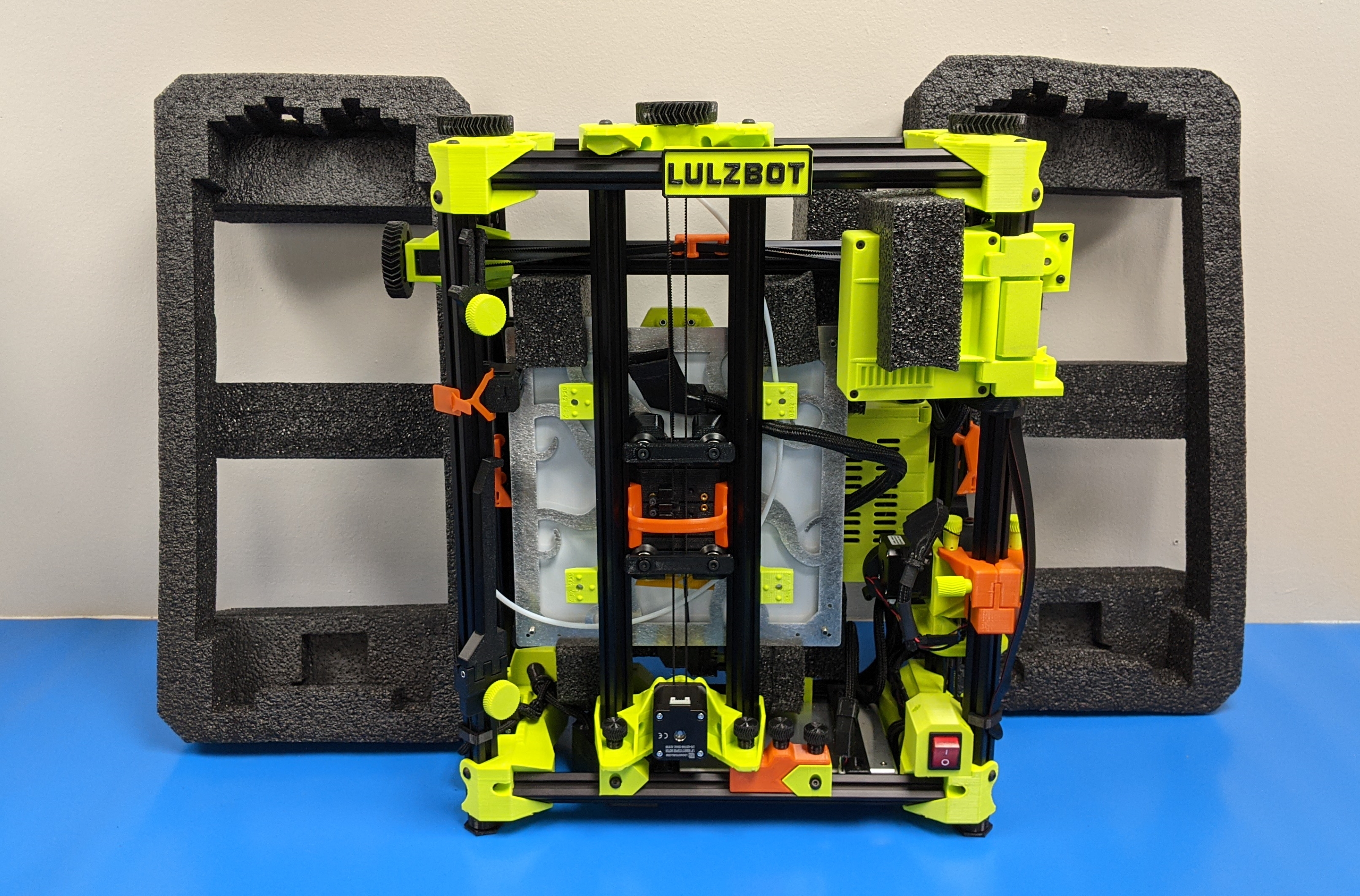
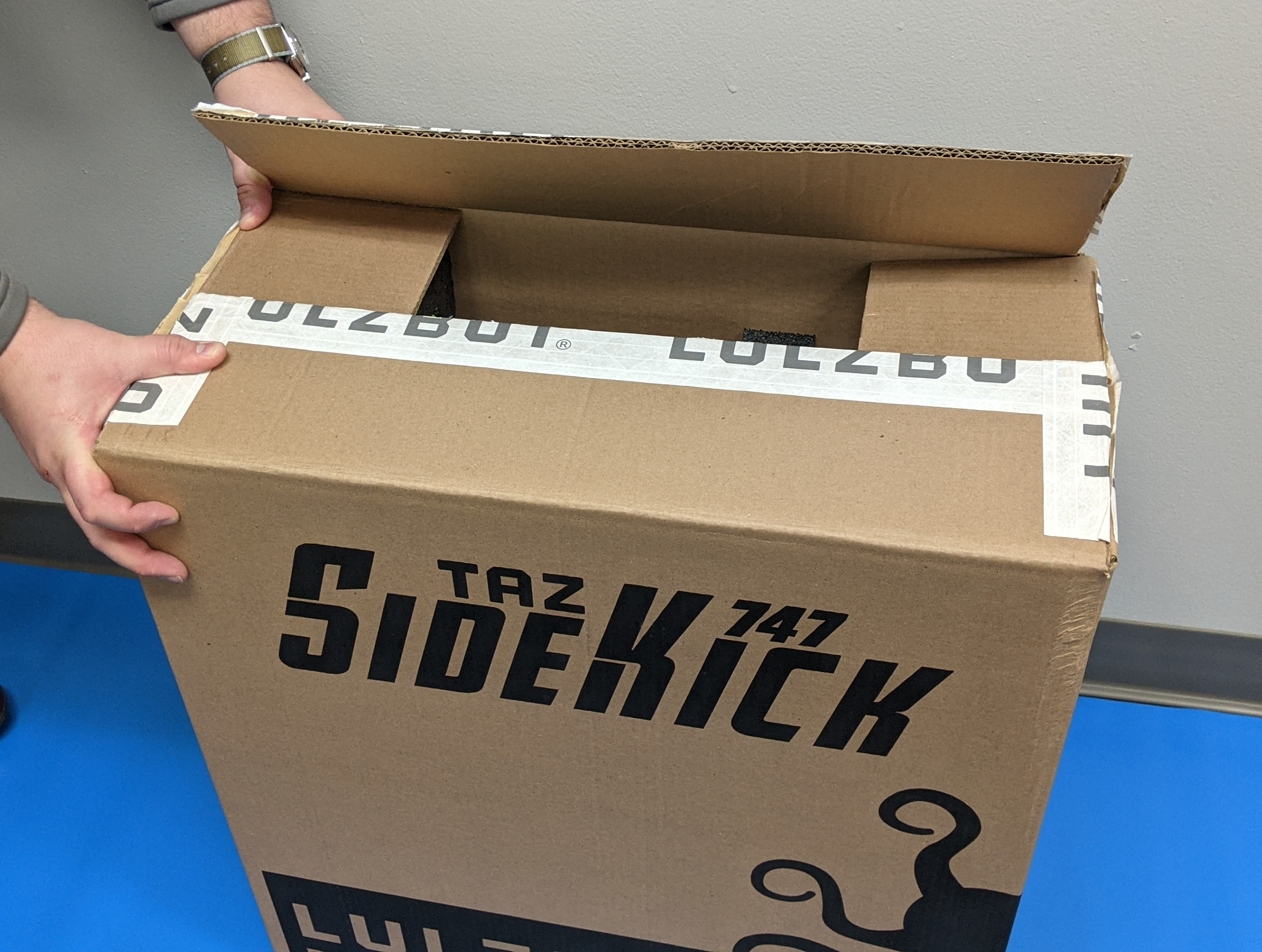
Place printer into SideKick box.
If you have any questions regarding packing your TAZ SideKick, you can reach out to our support team by sending an email to: support@lulzbot.com.
If you no longer have the 3d printed shipping components, you can find the stl files at our gitlab page located here.