Open HardwareAssembly Instructions
Guides for installation and assembly of the LulzBot line of products made by FAME 3D LLC.
Guides for installation and assembly of the LulzBot line of products made by FAME 3D LLC.
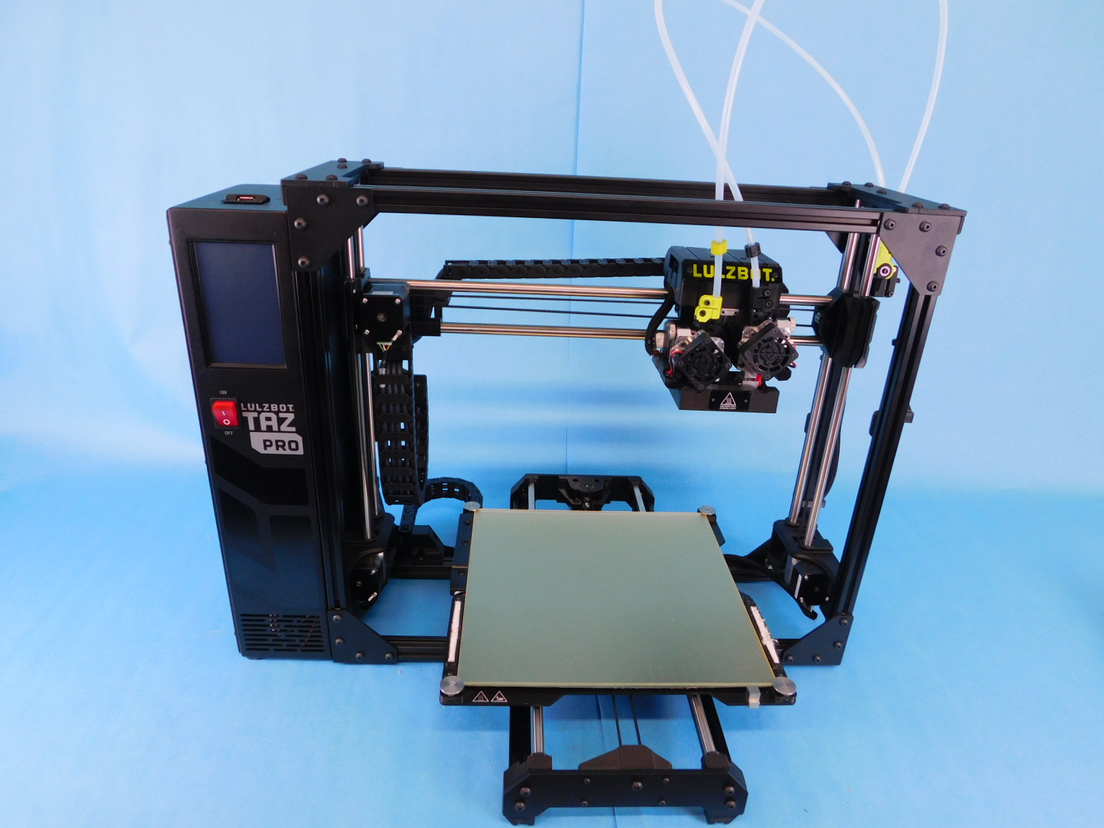
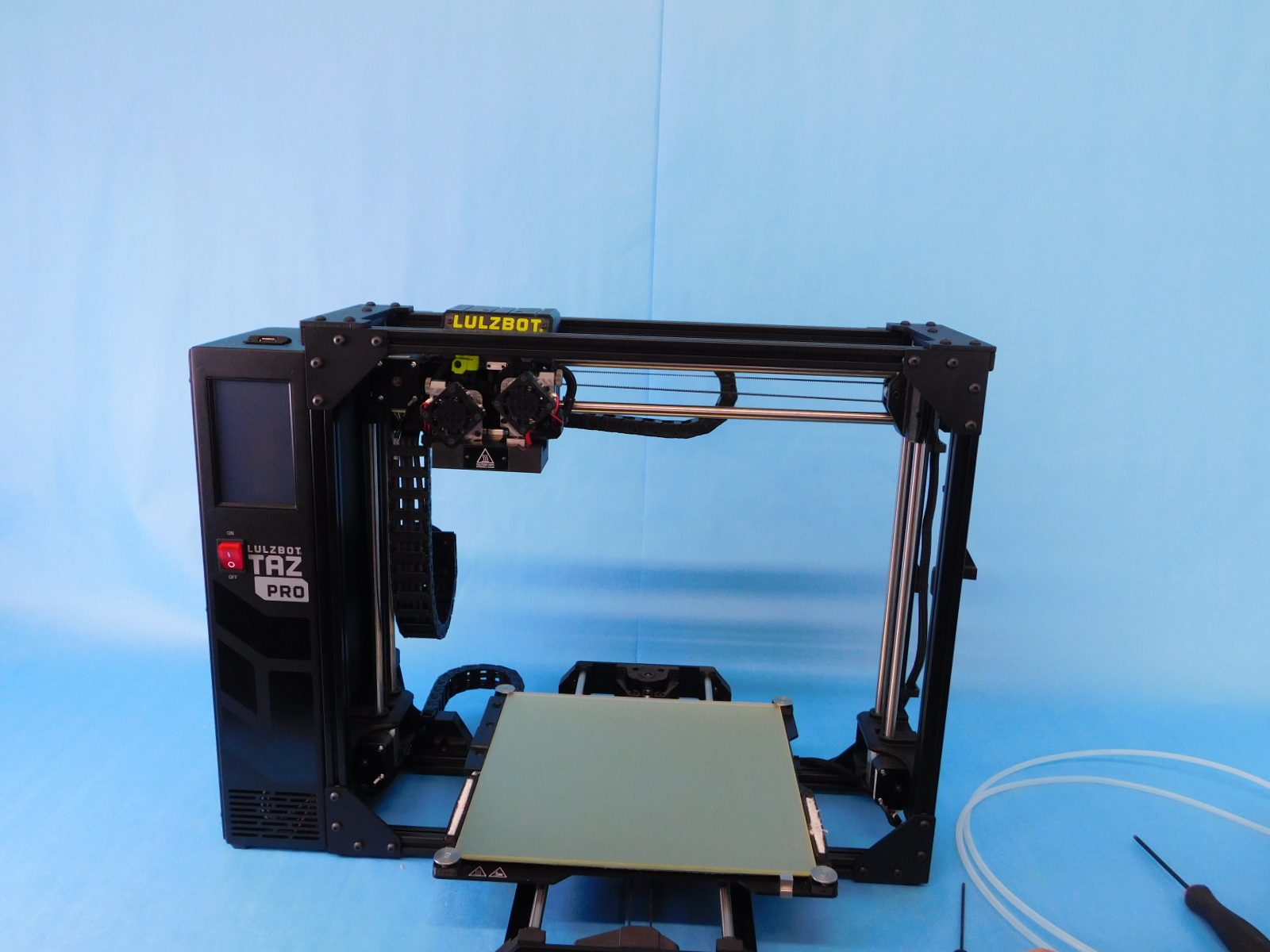
Obtain one calibrated TAZ Pro printer [AS-PR0148] from the boxing queue
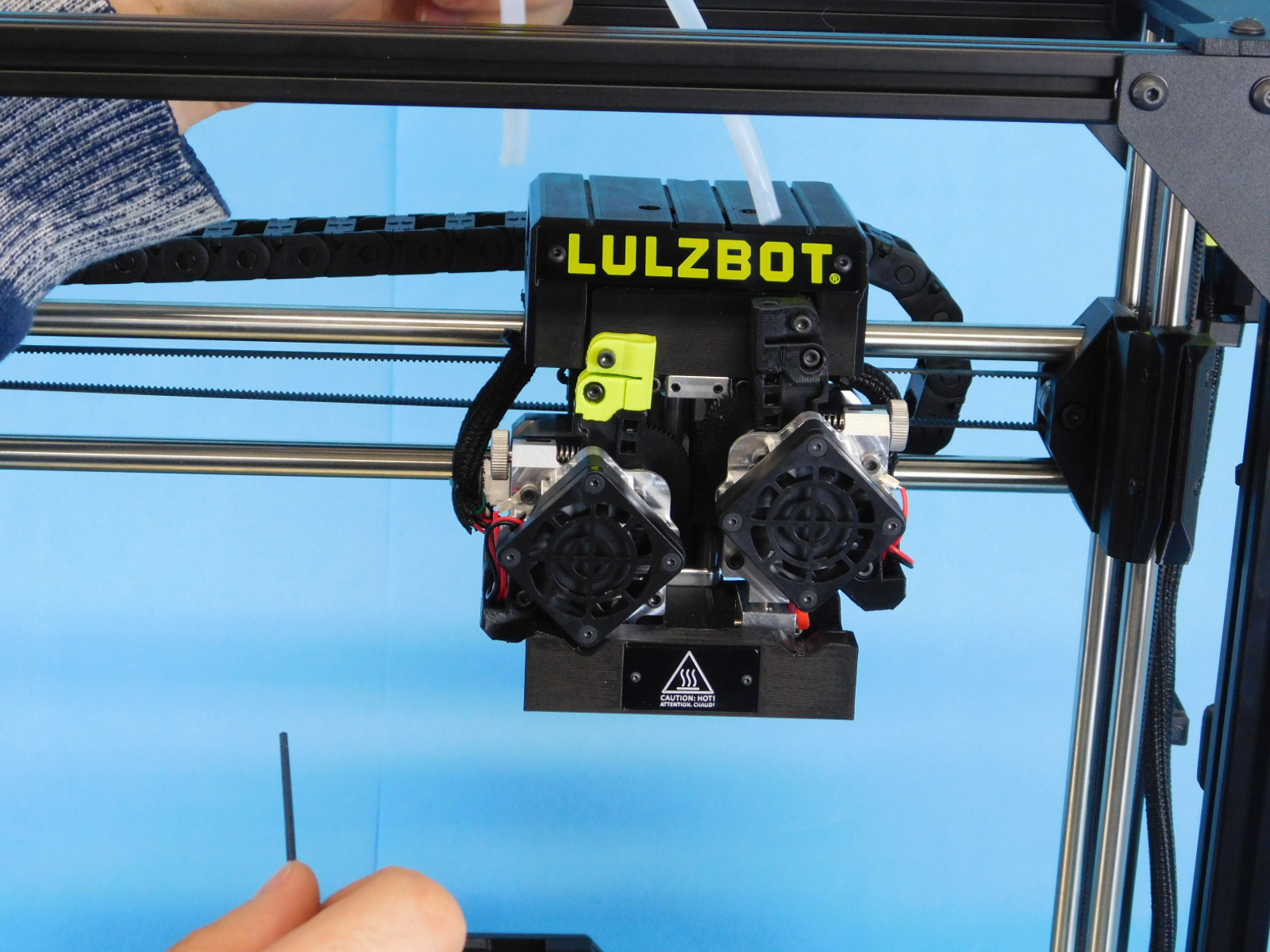
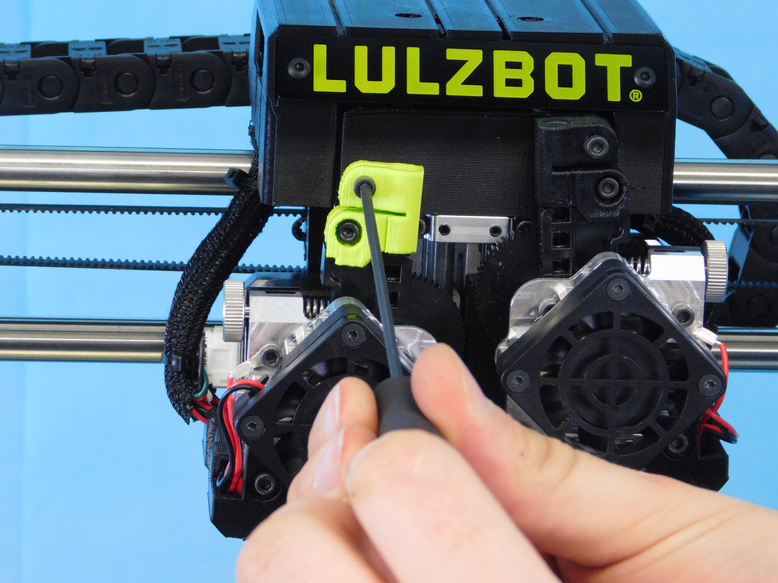
Remove the feed tubes from the Servo Dual Tool Head and the Filament Sensor.
Loosen the fasteners that are clamping the feed tube into the Idler Tube Clamps at the tool head.
Once the tube is removed, re-tighten the fastener so it will not vibrate loose in shipping.
Over-tightening may crack the printed parts, use caution.
The tubes can be easily removed from the filament sensor by pulling upwards.

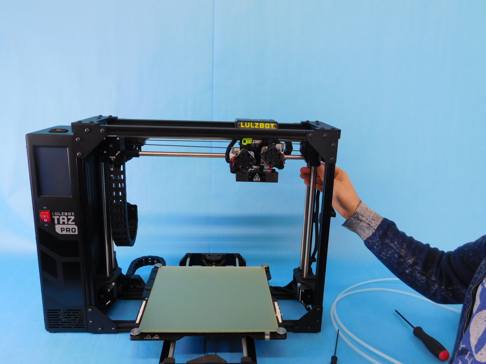
Put printer into shipping position by raising the z-axis all the way to the top and the tool head all the way to the left.
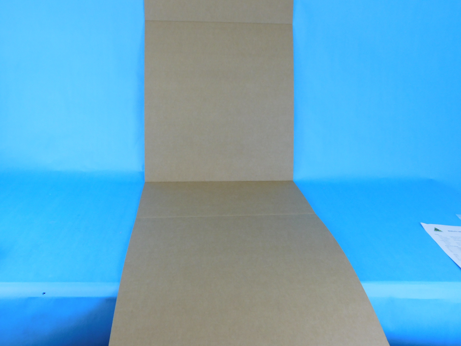
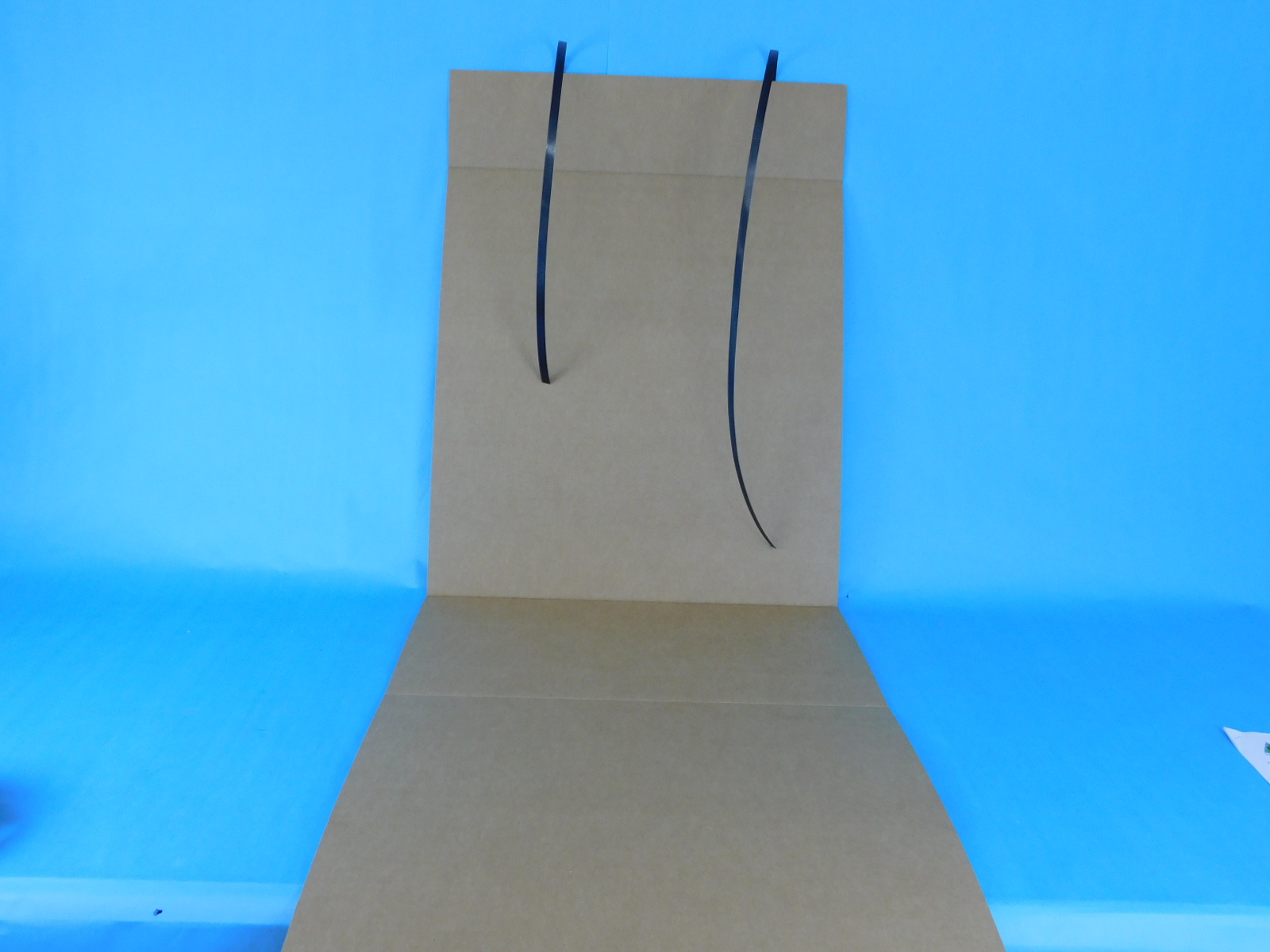
Obtain one TazPro, Corrugated Sleeve [SH-PA0063] and run two straps underneath it.
Disconnect all 3 connectors at the bed end of the Bed Harness, bed heat, thermistor, and ground.
Disconnect both connectors at the Y-Axis Motor.
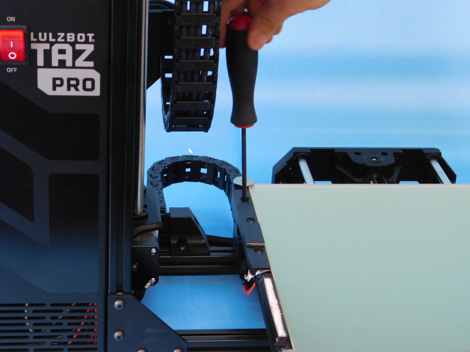
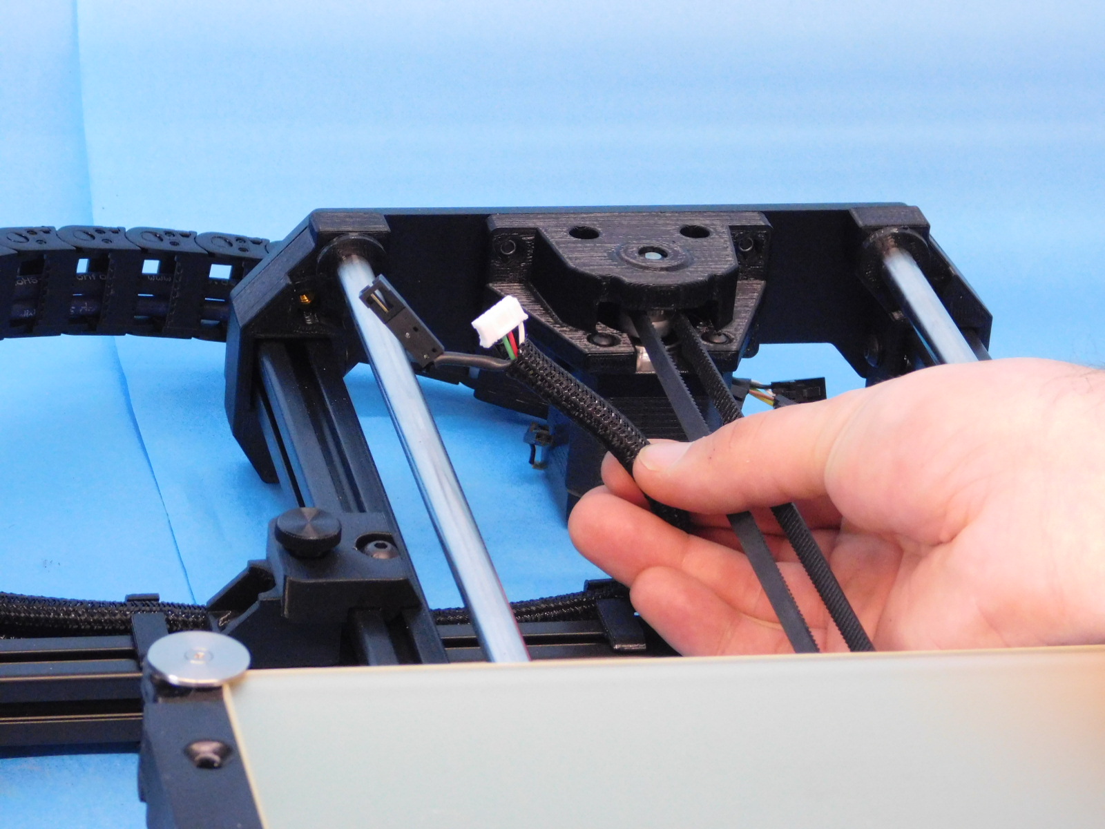
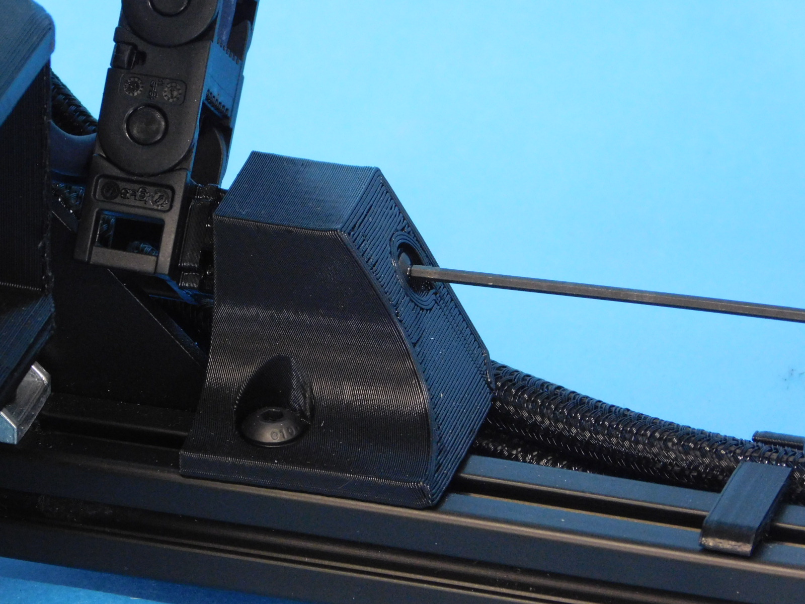
Using a 4mm Ball-tipped Hex Driver through the hole in the Y-Cable Cover and Bed Plate, loosen the M5 fastener securing the Y-Cable Chain to the Y-Cable Cover. Continue to turn counter-clockwise until the cable chain is free from the bed.
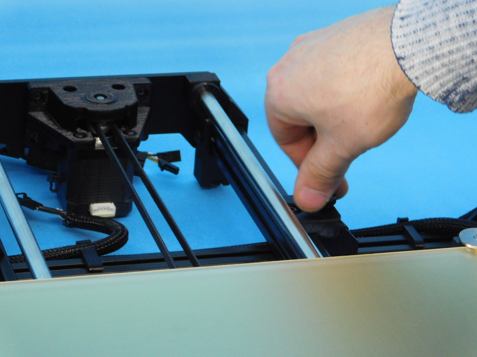
Remove the four M5 thumb screws that secure the Y-Axis to the frame.
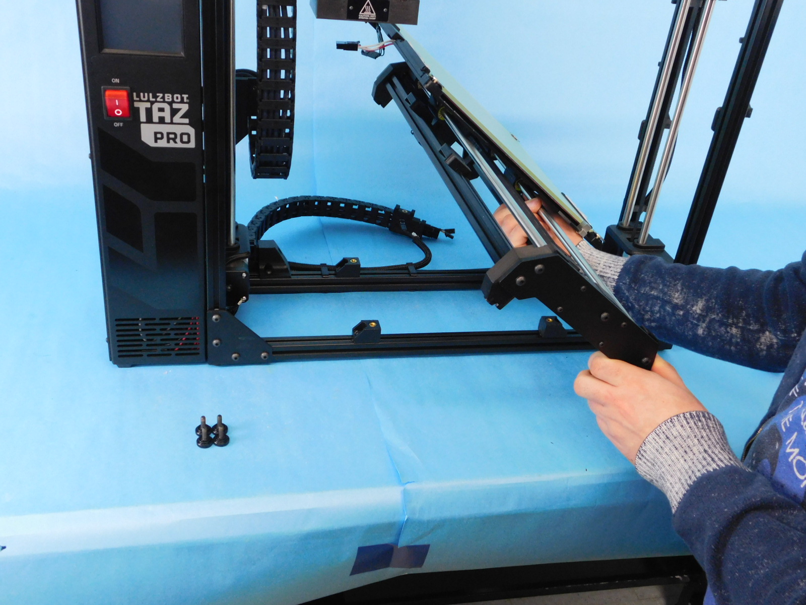
Lift the Y-Axis from the frame and place it out of the way.
Re-install the M5 thumb screws into the chassis mounts, finger tight so that they do not vibrate loose during shipping.


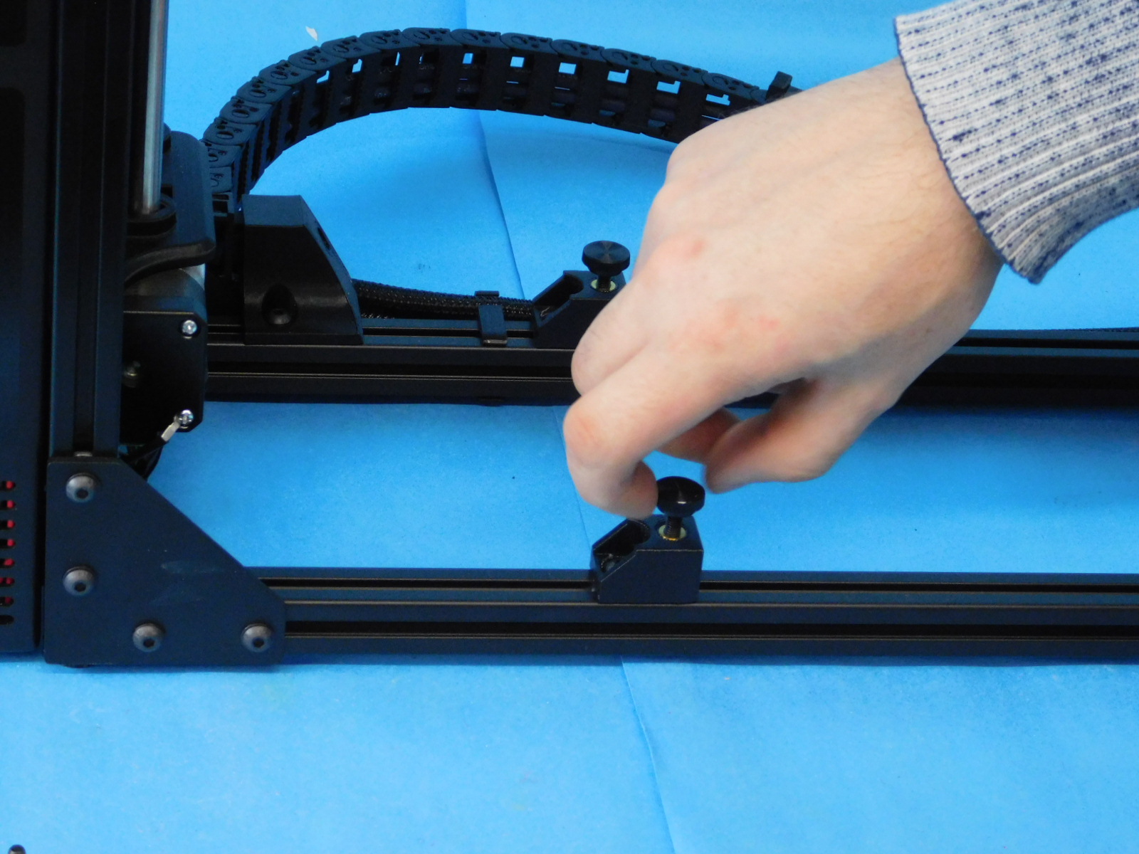

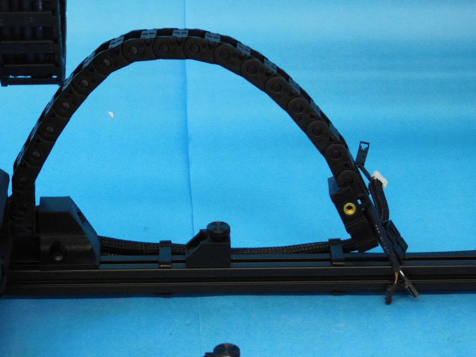
The Y-Cable Chain must be rotated into shipping position.
To do so, pull the Y-Chain Mount at the frame towards the Control Box (machine left) and pivot the chain end counter clockwise.
It should rest in this position.
Flip the y-cable chain to an upright position. Using a M2 ball hex driver loosen the screw holding the chain to the pivot mount. This screw does not need to be completely removed, just loose enough to pivot the chain upwards, then re-tighten the screw to hold the chain in that position.
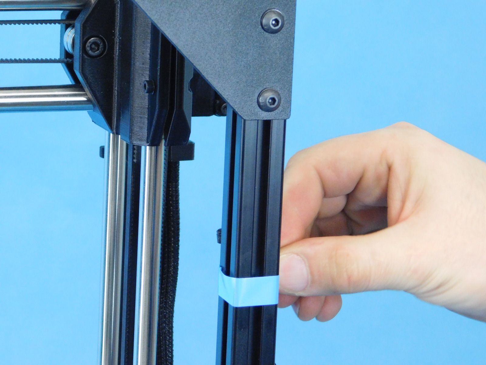
Add a piece of tape to each spool arm to hold them in place. The tape only needs to be long enough to wrap around the spool arm 1.5 times. Make sure to make a little tab on the tape for easy removability.

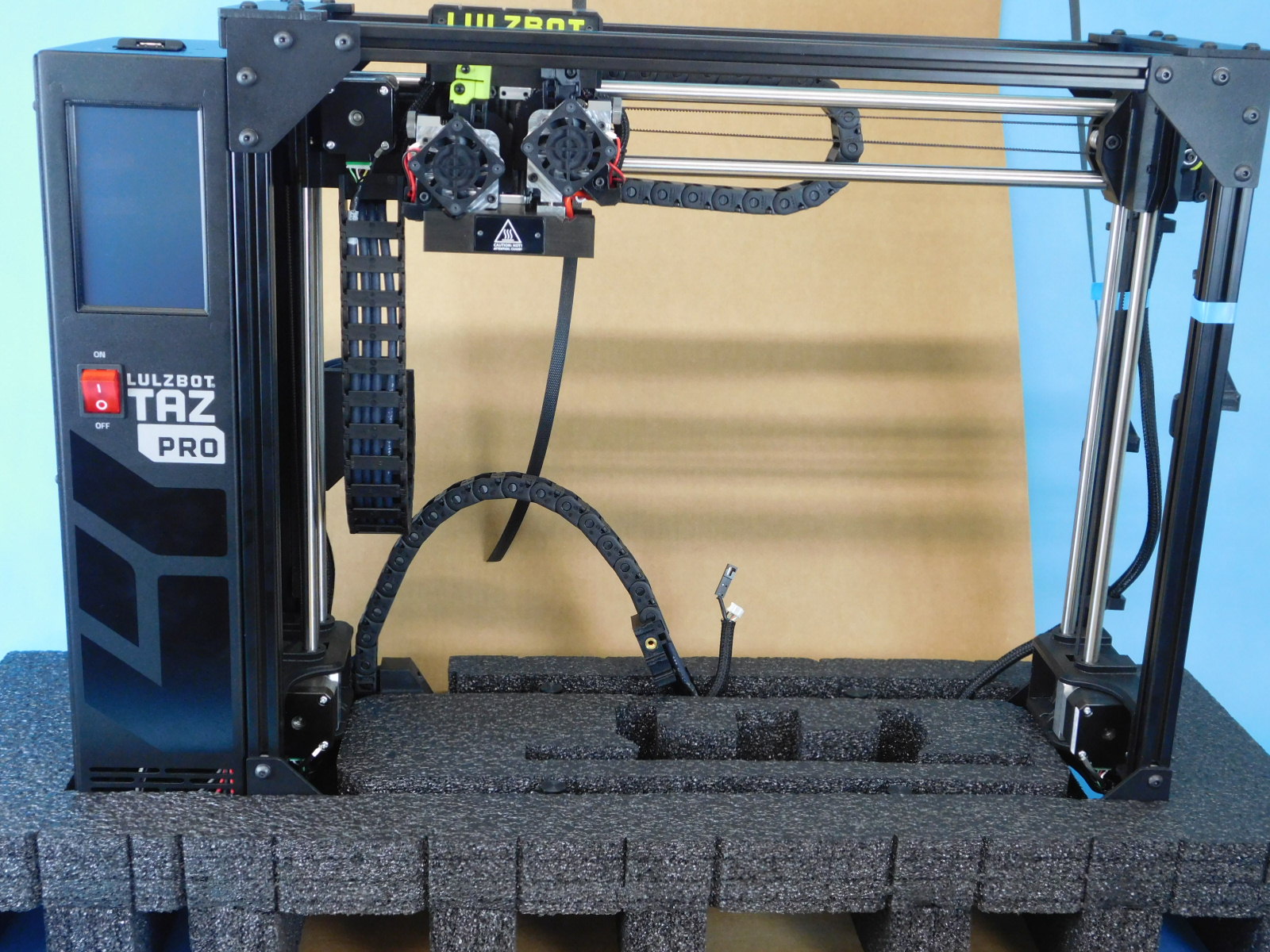
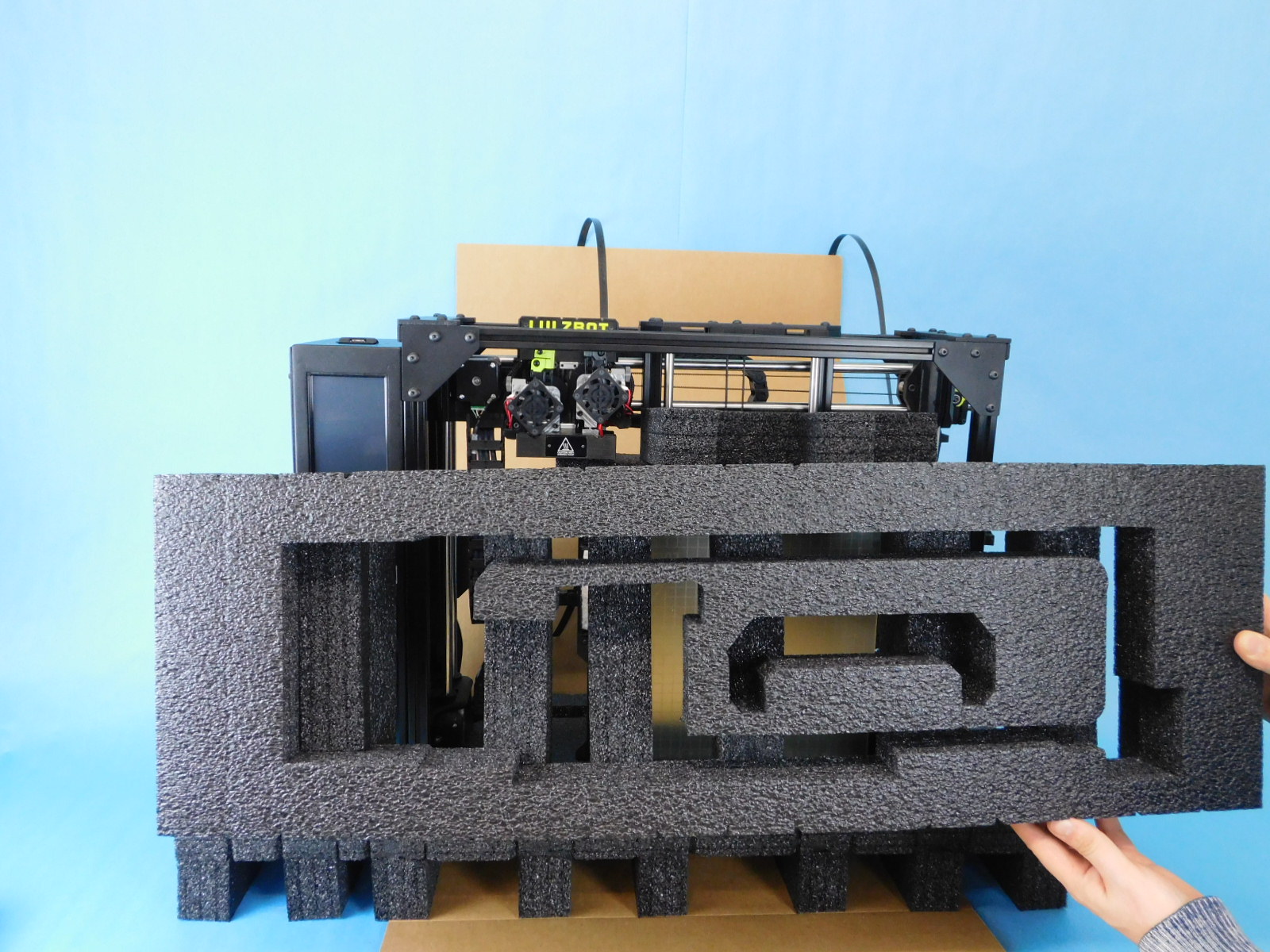
Place the bottom foam piece [AS-PA0061] onto the card board.
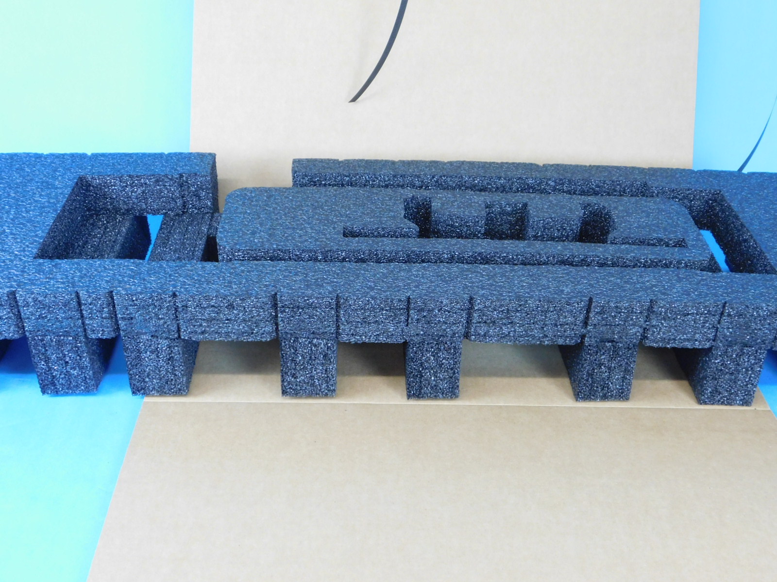
Place the frame into the bottom foam piece.
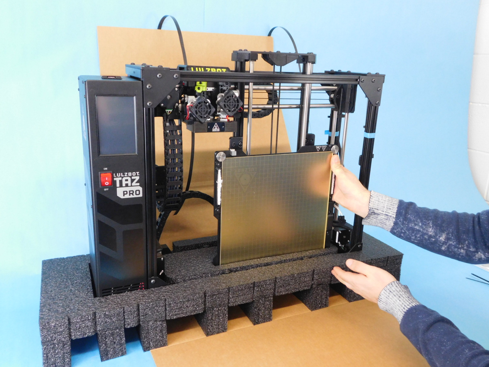
Place the y-axis into the bottom piece of foam with the motor on the bottom and facing the rear of the printer. You may need to support the foam underneath while placing the y-axis into the foam. The top side of the axis should be about level with the top of the frame.
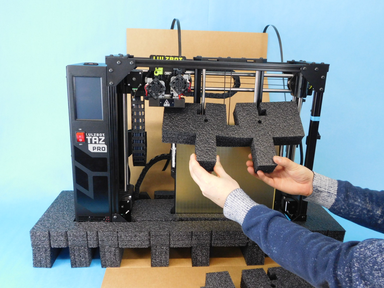
Place the two middle pieces around the y-axis. This will support both the tool head and the x-axis. First place the larger piece [SH-PA0062] then place the smaller piece [AS-PA0064] on top of that.
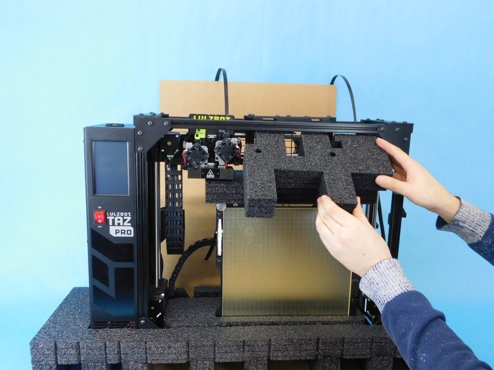

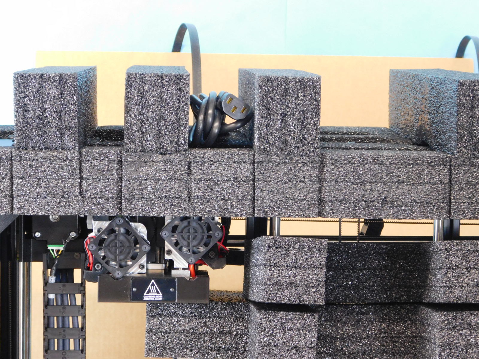
Add the top piece of foam [AS-PA0060] to the printer.

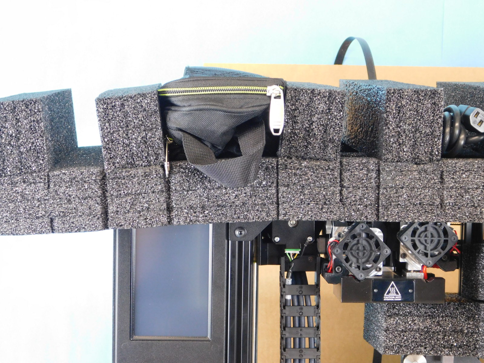
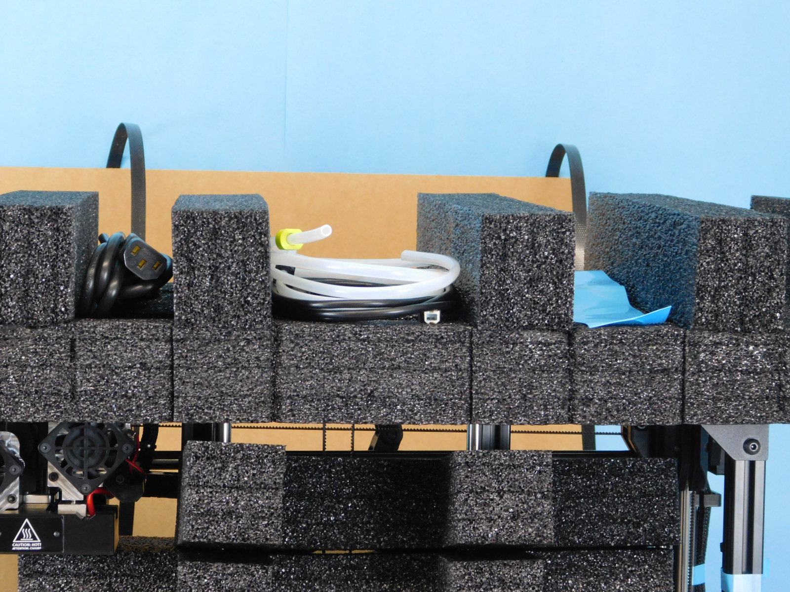
Add the tool kit, cables, and feed tubes in the top piece of foam.

Use the strapping tool to tighten and seal the printer.
