Open HardwareAssembly Instructions
Guides for installation and assembly of the LulzBot line of products made by FAME 3D LLC.
Guides for installation and assembly of the LulzBot line of products made by FAME 3D LLC.
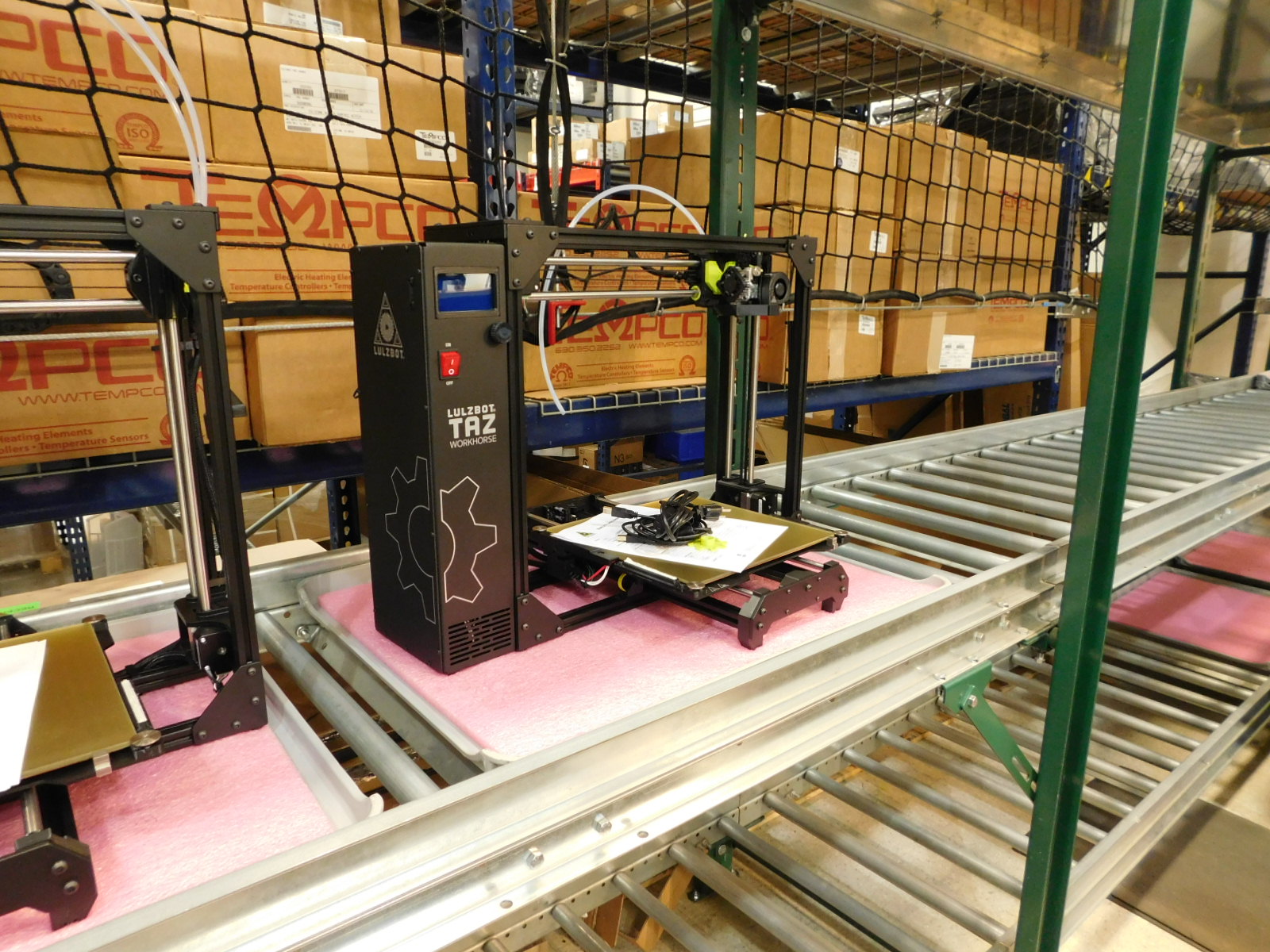
One calibrated TAZ Workhorse Edition 3D printer [AS-PR0168] has arrived on the boxing queue.
Several of these may be prepared in advance
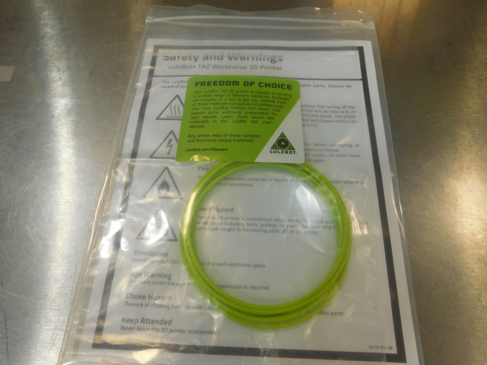
Obtain the following materials:
1x- [SH-PG0030] 8x10" 2 MIL Reclosable Bag
1x- [SH-PG0084] 6x10" 6 MIL Reclosable Bag
1x- [DC-LB0187] Label - TAZ Filament Sample Bags
3m- [RM-PL0134] Polylite PLA LulzBot Green, 2.85mm - Polymaker
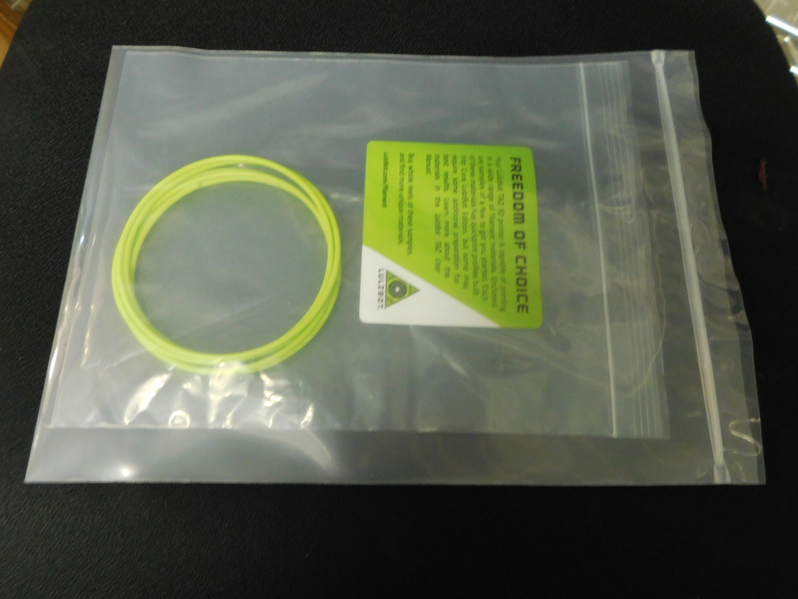
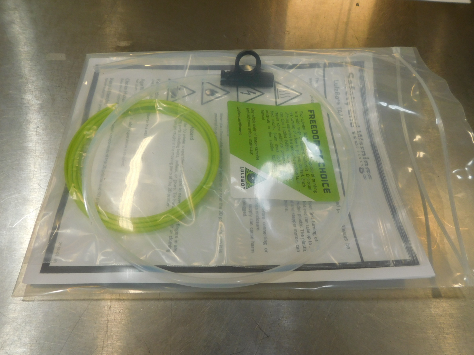
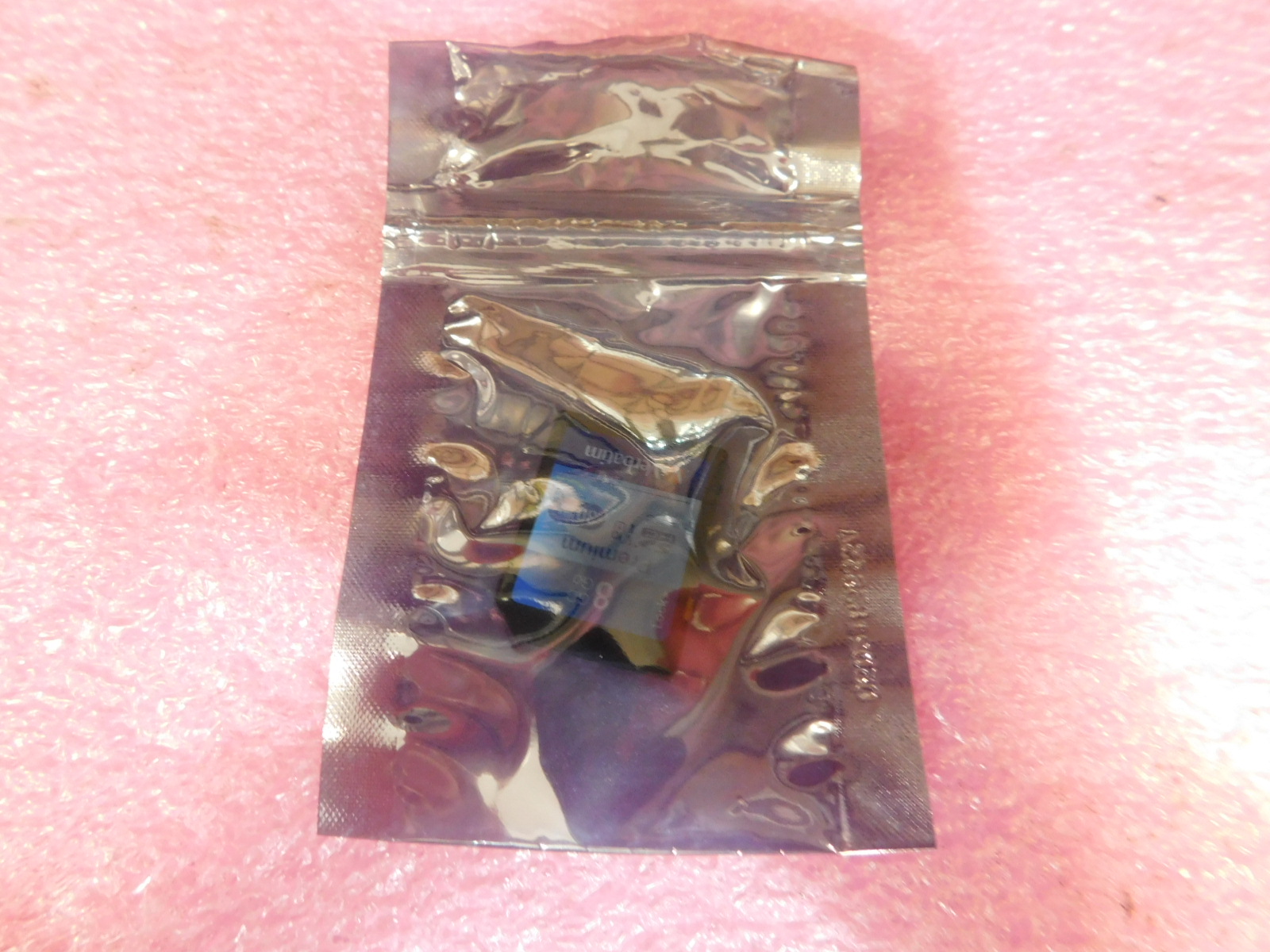
Place the 3 meter sample of LulzBot Green Polylite PLA [RM-PL0134] into the 6x10" Reclosable Bag [SH-PH0084] and seal the bag.
Place one TAZ Filament Sample Bag Label [DC-LB0187] onto the 6x10" Reclosable Bag [SH-PH0084]
Place the completed Filament Sample Bag into the 8x10" Reclosable Bag [SH-PG0030]

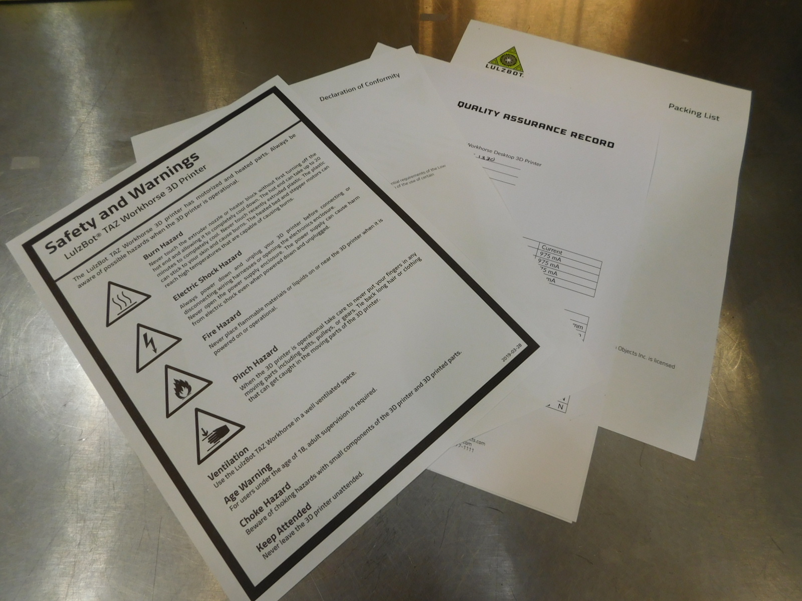
Obtain the following:
1x- [DC-MS0092] Declaration of Conformity
1x- [DC-MS0093] Safety & Warnings
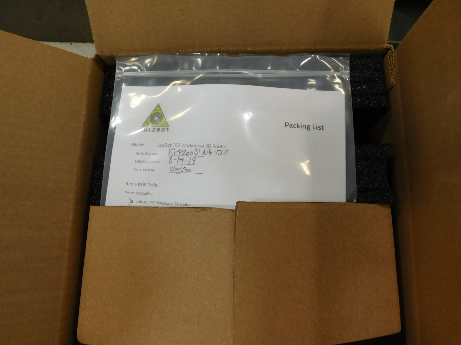
1x- [DC-MS0094] Packing List
1x- [AS-PK0040] Document Bag
1x- [AS-PK0041] Quick Start Guide Pack
1x- Completed Quality Assurance Record
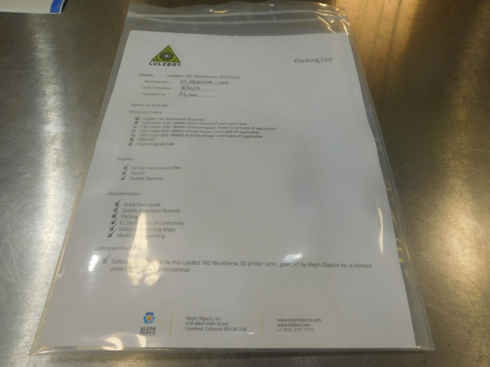
Ensure all checks in the Quality Assurance Record are complete and filled out legibly.
Fill out the Packing List [DC-MS0094] by checking off the items that are being shipped with the printer.
Stack the documents in the following order:
1- Packing List
2- Declaration of Conformity
3- Quality Assurance Record
4- Safety & Warnings
Flip the Safety & Warnings page over, so that when inserted into the document bag the safety and warnings is visible.
Bend (do not fold or crease) the stack of documents lengthwise to insert them into the document bag and then press them flat.
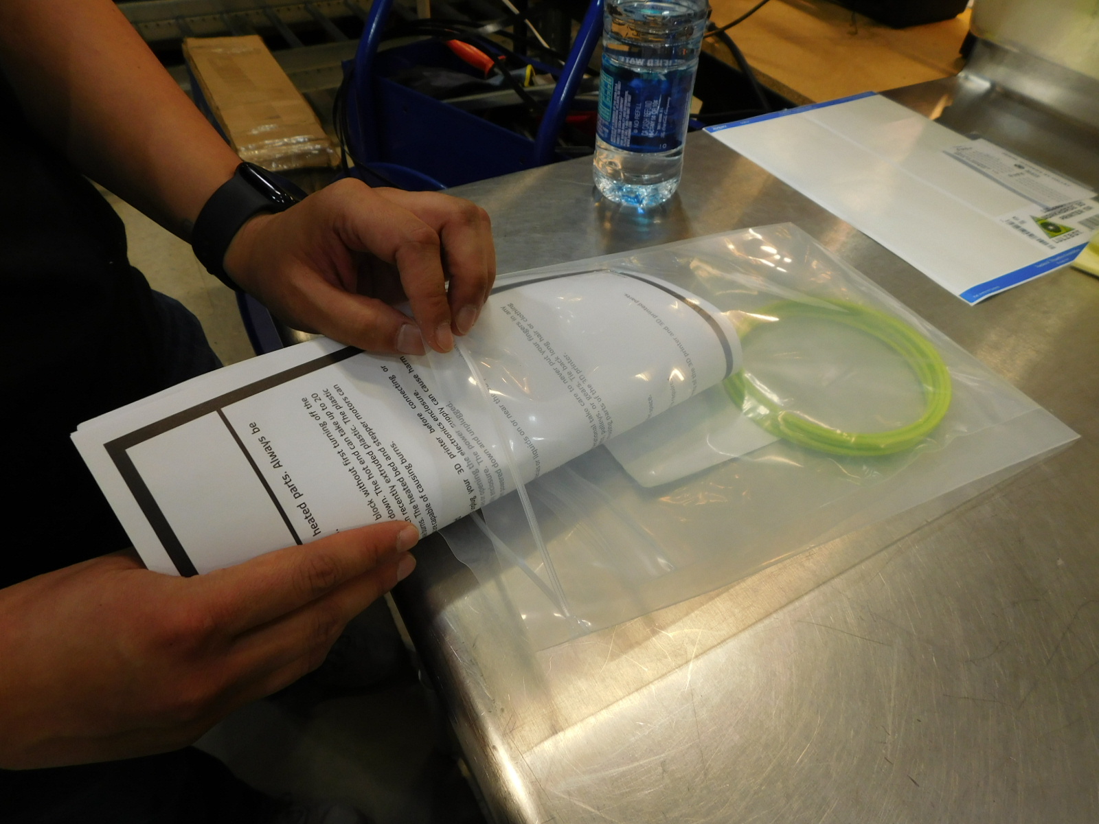
Remove the Feed Tube Assembly from the feed tube holder and from the Idler Tube Clamp on the tool head.
Once the tube is removed, re-tighten the fastener on the Idler Tube Clamp so it will not vibrate loose in shipping.
Over-tightening may crack the printed parts, use caution.
Place the Feed Tube Assembly into the document bag as pictured.
Place 1x [TL-HD0588] 2" print bed scraper inside the documentation bag
Several of these may be prepared in advance
Obtain the following materials:
1x- [DC-LB0095] Lulzbot Logo Sticker 3"
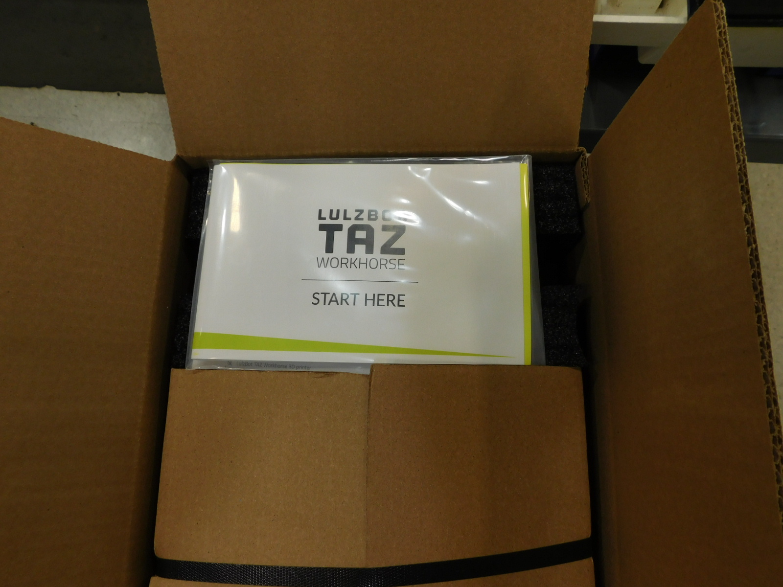
1x- [DC-MN0020] Quick Start Guide, TAZ Workhorse
1x- [DC-MS0076] Cura update insert card
1x- [SH-PG0083] 9x12" 8 mil reclosable bag
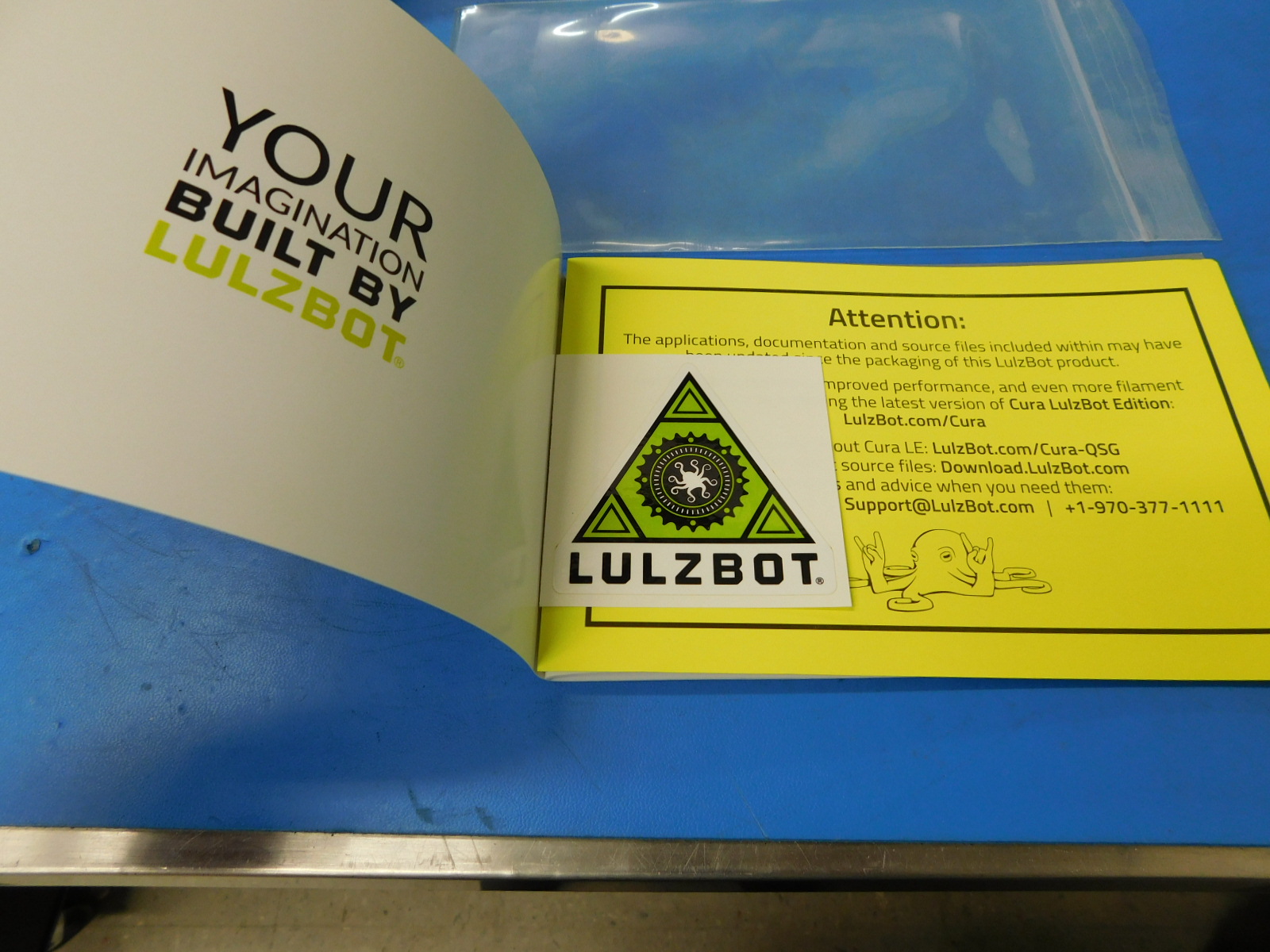
Place the Lulzbot Logo Sticker [DC-LB0095] and the Cura Update Insert Card [DC-MS0076] inside the front cover of the Quick Start Guide [DC-MN0020] as pictured.
Insert the Quick Start Guide into the 9x12" Bag [SH-PG0083] and seal the bag.


Required materials:
1x- [AS-PK0029] Universal Tool Kit
1x- [SH-PG0031] 2x3"Reclosable ESD safe bag
1x- [EL-MS0523] Power Connector Heavy Duty Retention Clip
Place the Retention Clip [EL-MS0523] into the large main pocket of the Universal Toolkit bag [AS-PK0029]
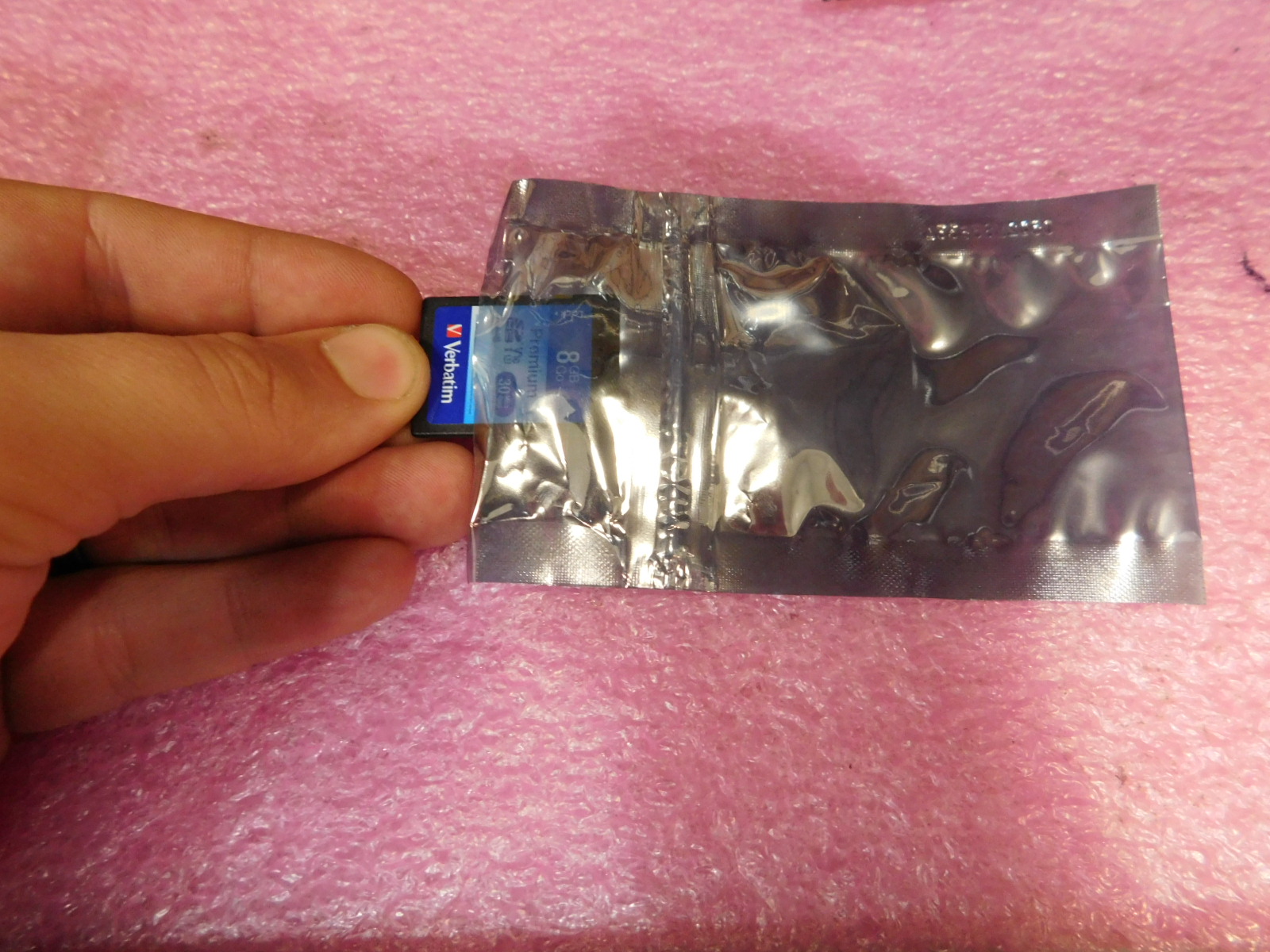
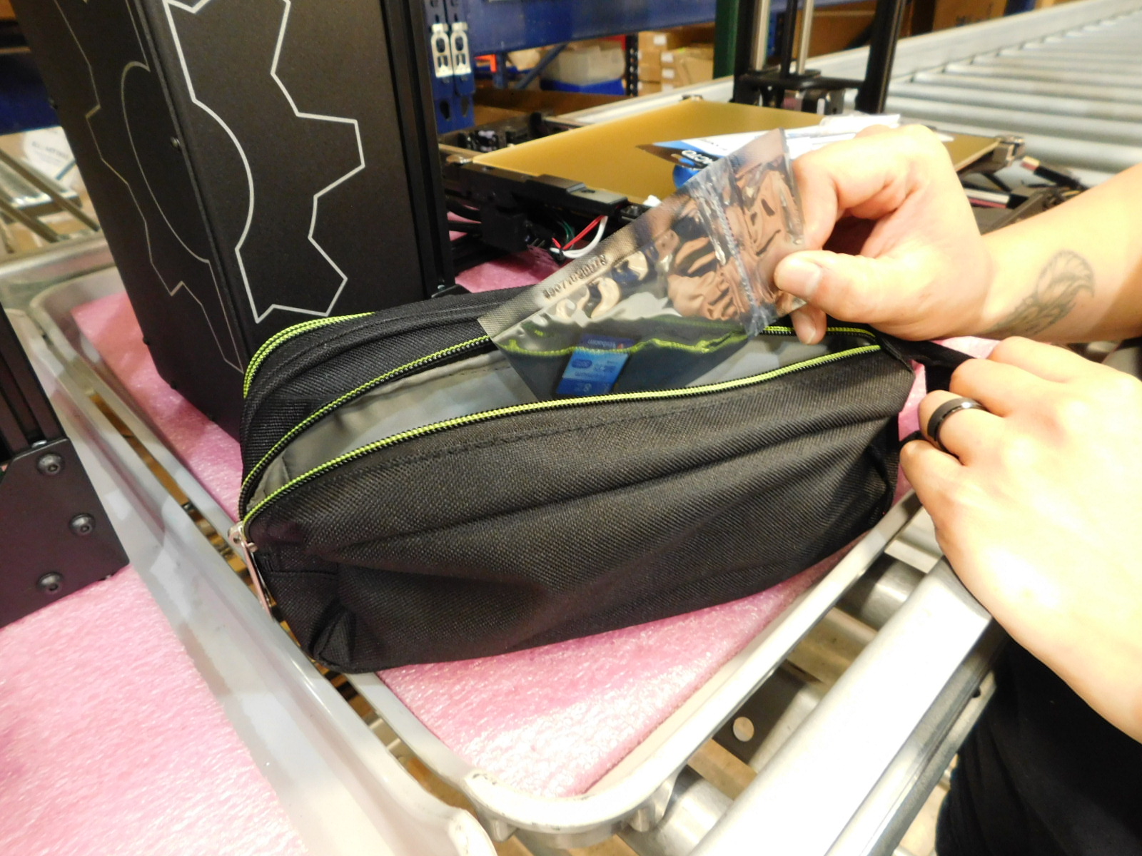
Remove the SD card from the side of the unit to be packaged and insert it into the 2x3" Reclosable ESD safe bag [SH-PG0031] and seal the bag.
Place the ESD bag with SD card into the large main pocket of the tool kit bag.
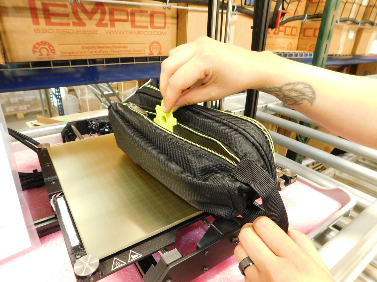
Place the completed Octogear sample print from the unit to be packaged into the large main pocket of the Universal Toolkit.
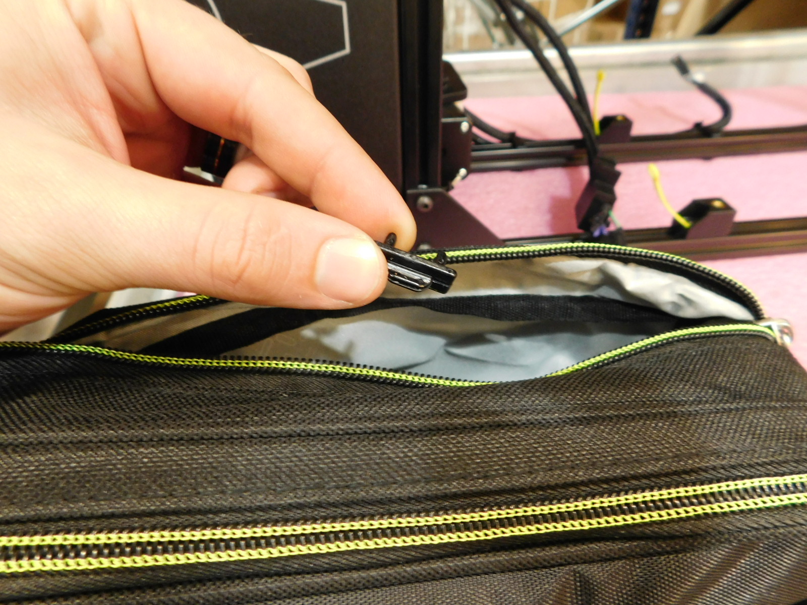
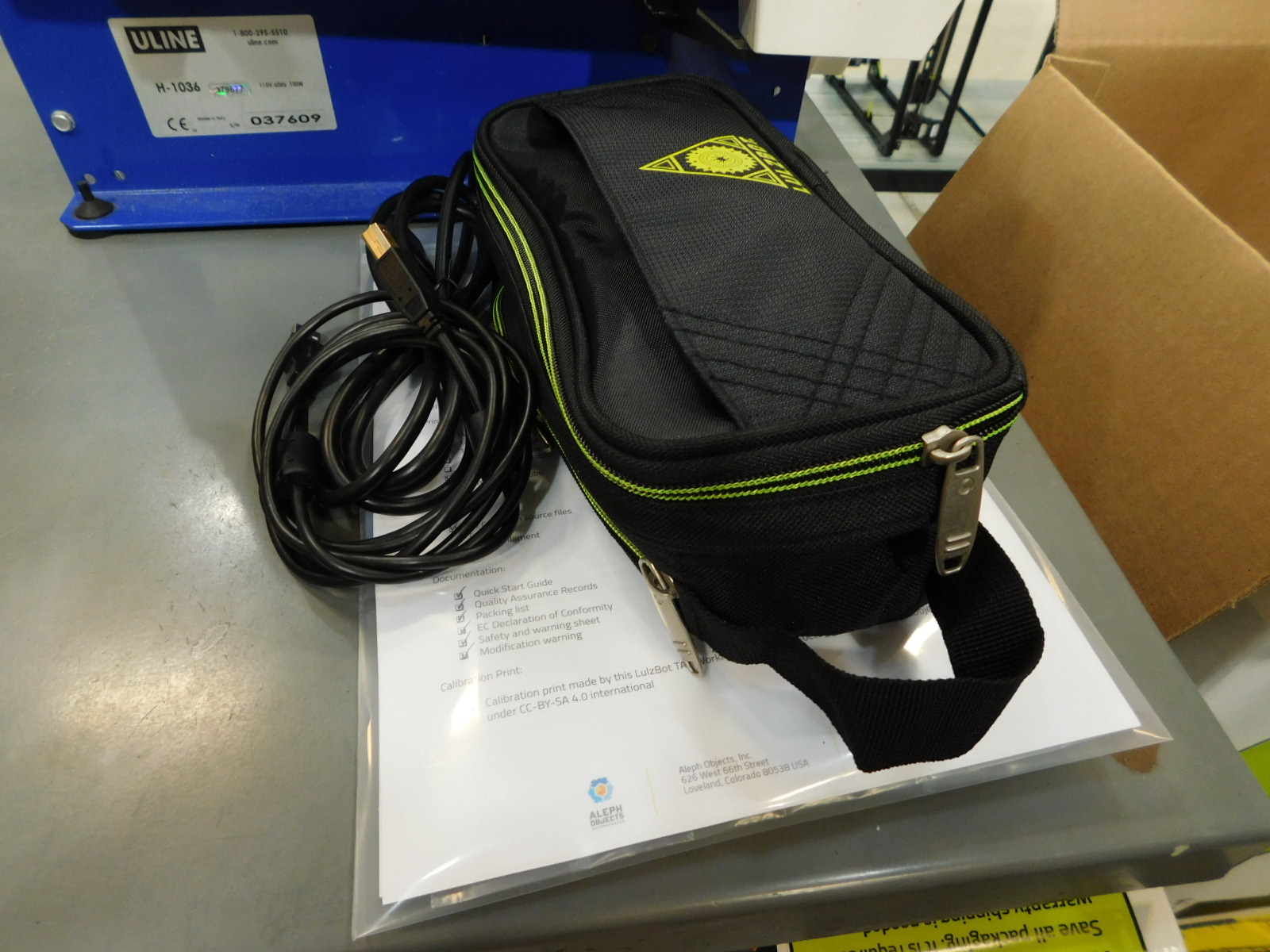
Zip all pockets of the Universal Tool Kit closed and place it to the side along with the completed document bag and the power/usb cables from the unit.

Obtain one TAZ, Corrugated Sleeve [SH-PA0063] and bend along the creases into a "U" shape.
Stand this up on the floor.
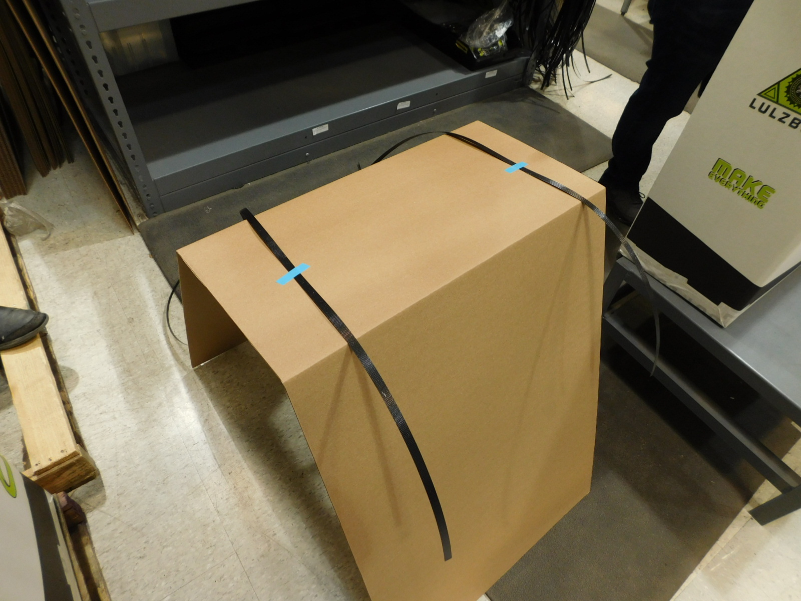
Cut two sections of Economy Strapping [SH-PG0069] approximately 7ft 4inches long.
Place them over the Corrugated Sleeve [SH-PA0063] as pictured, note that more length is to one side.
Secure them in place using two short lengths of narrow blue strapping tape.
Several of these may be prepared in advance, as space allows.
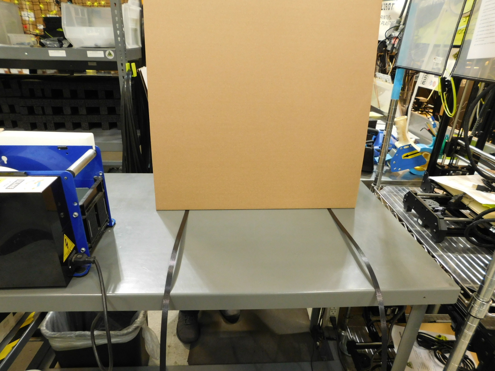
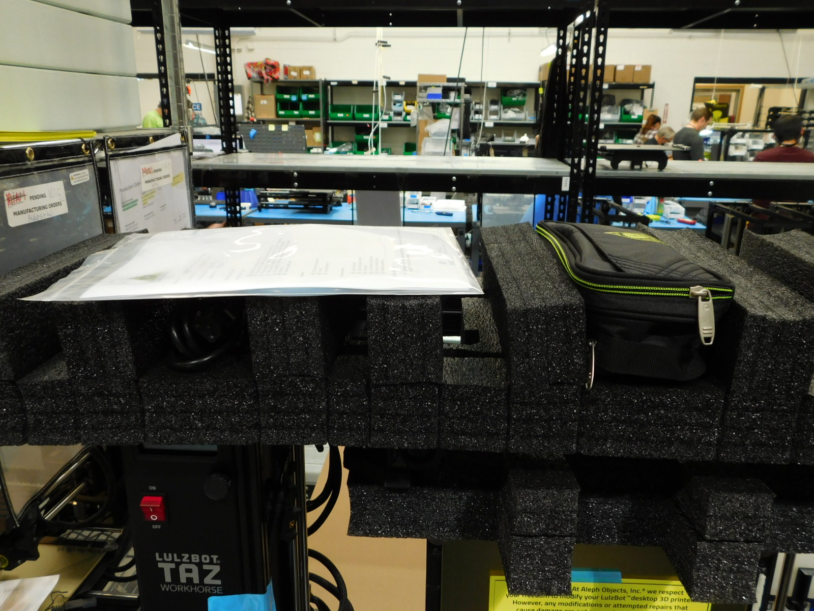
Place the prepared Corrugate Sleeve on the workbench with the strapping facing down and the longer length of the strapping away from you.
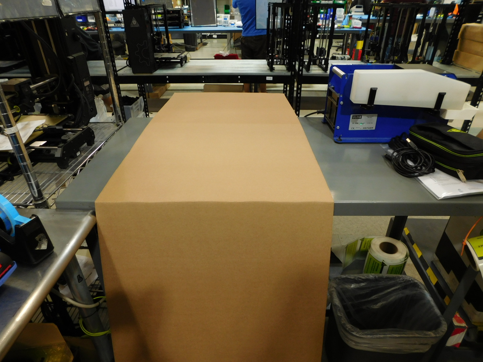
Bend the Corrugate Sleeve down so that the front bottom crease is against the front edge of the workbench, as pictured.
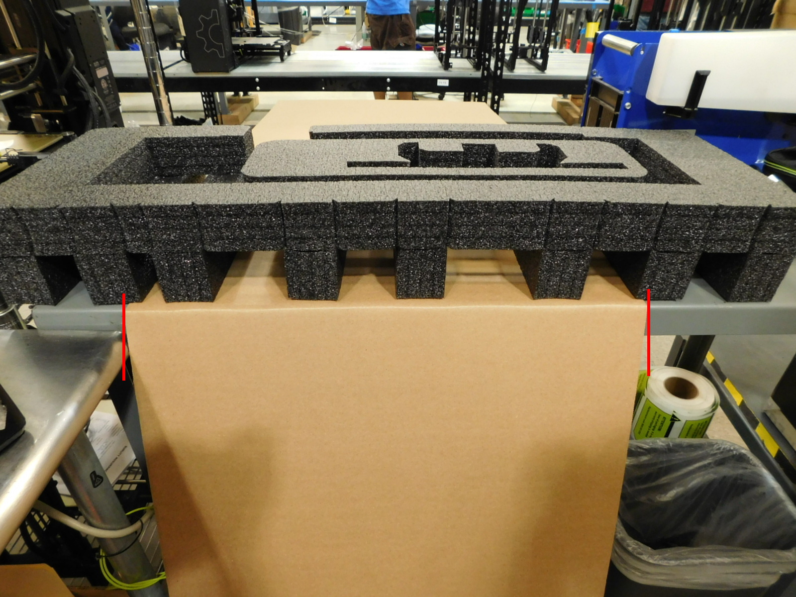
Obtain one Bottom Endcap Foam [SH-PA0061] and place it on the Corrugated Sleeve as pictured.
Note the alignment of the Bottom Endcap Foam with the Corrugated Sleeve.
If the Z-Axis is not at the top of travel when you receive it, connect power to the printer and turn it on. The unit will automatically home the Z-Axis to the top.
Turn off and disconnect power from the unit
You can now move the tool head by hand all the way to the left end of travel if it isn't there already.

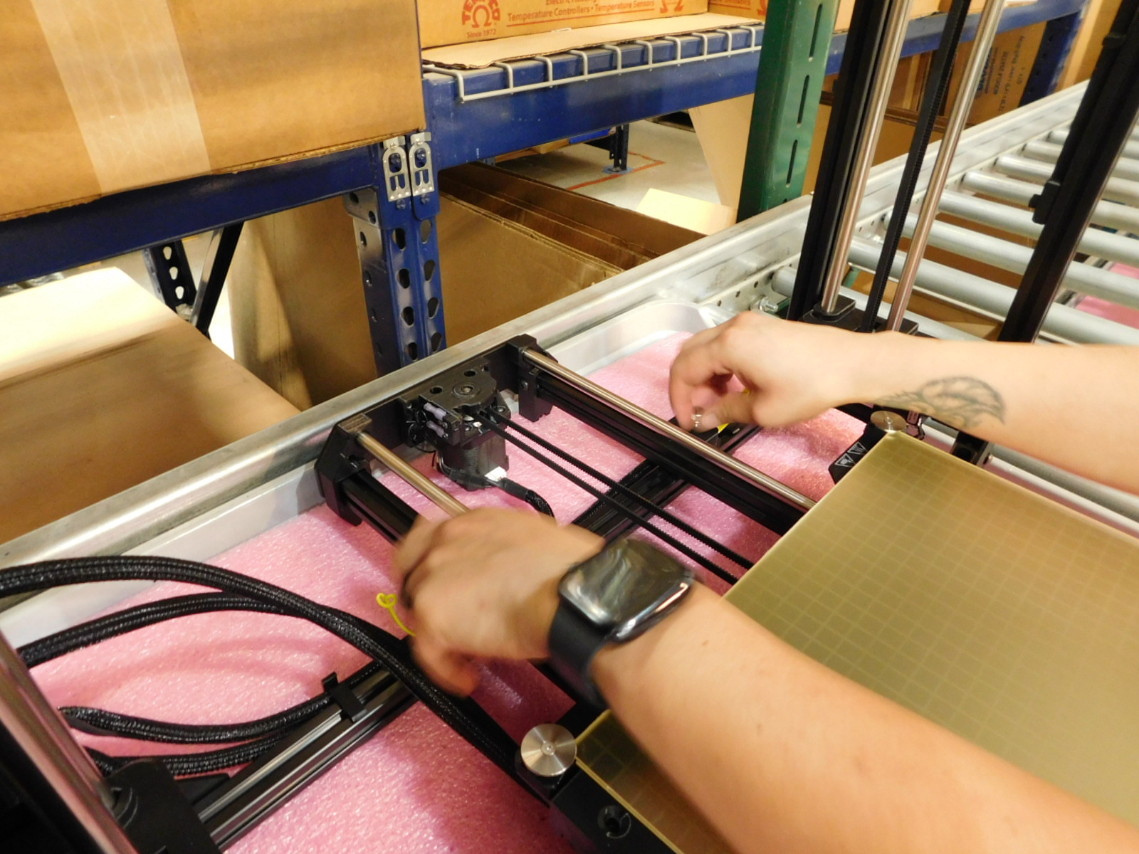
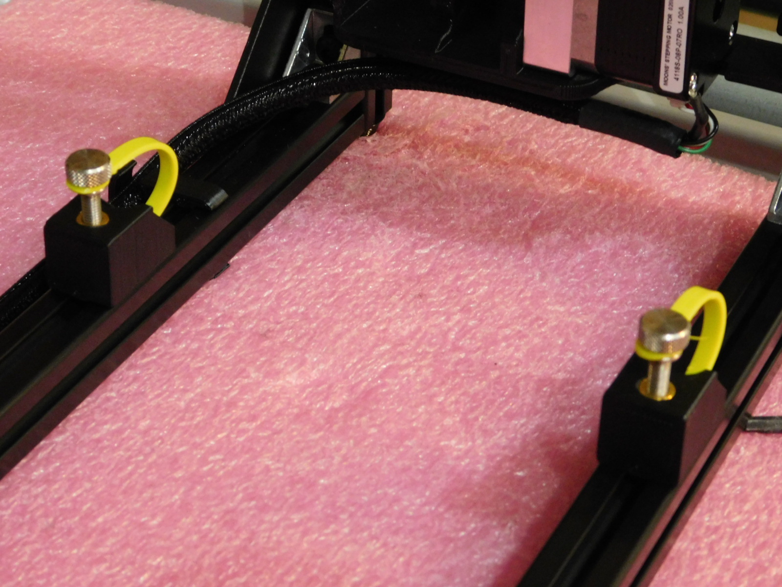
Slide the print bed towards you and remove the rear two thumb screws securing the Y-Axis to the frame.
Slide the bed to the rear and remove the front two thumb screws securing the Y-Axis to the frame.
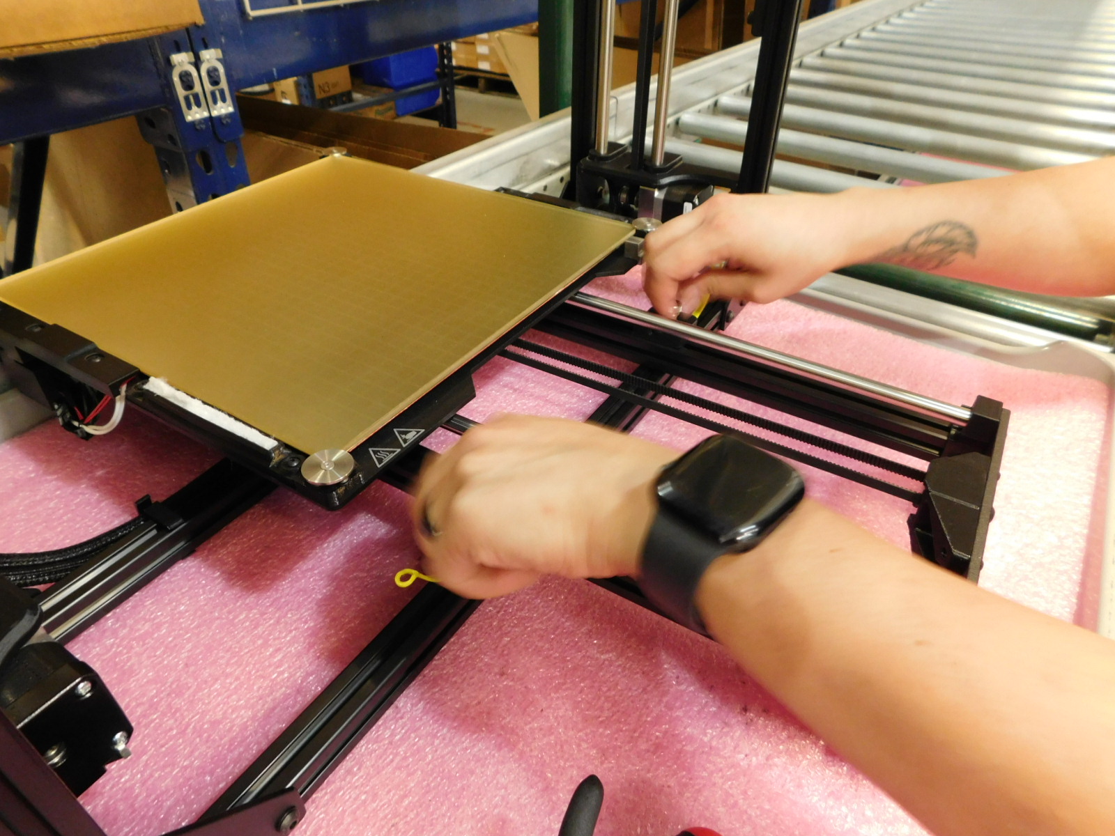
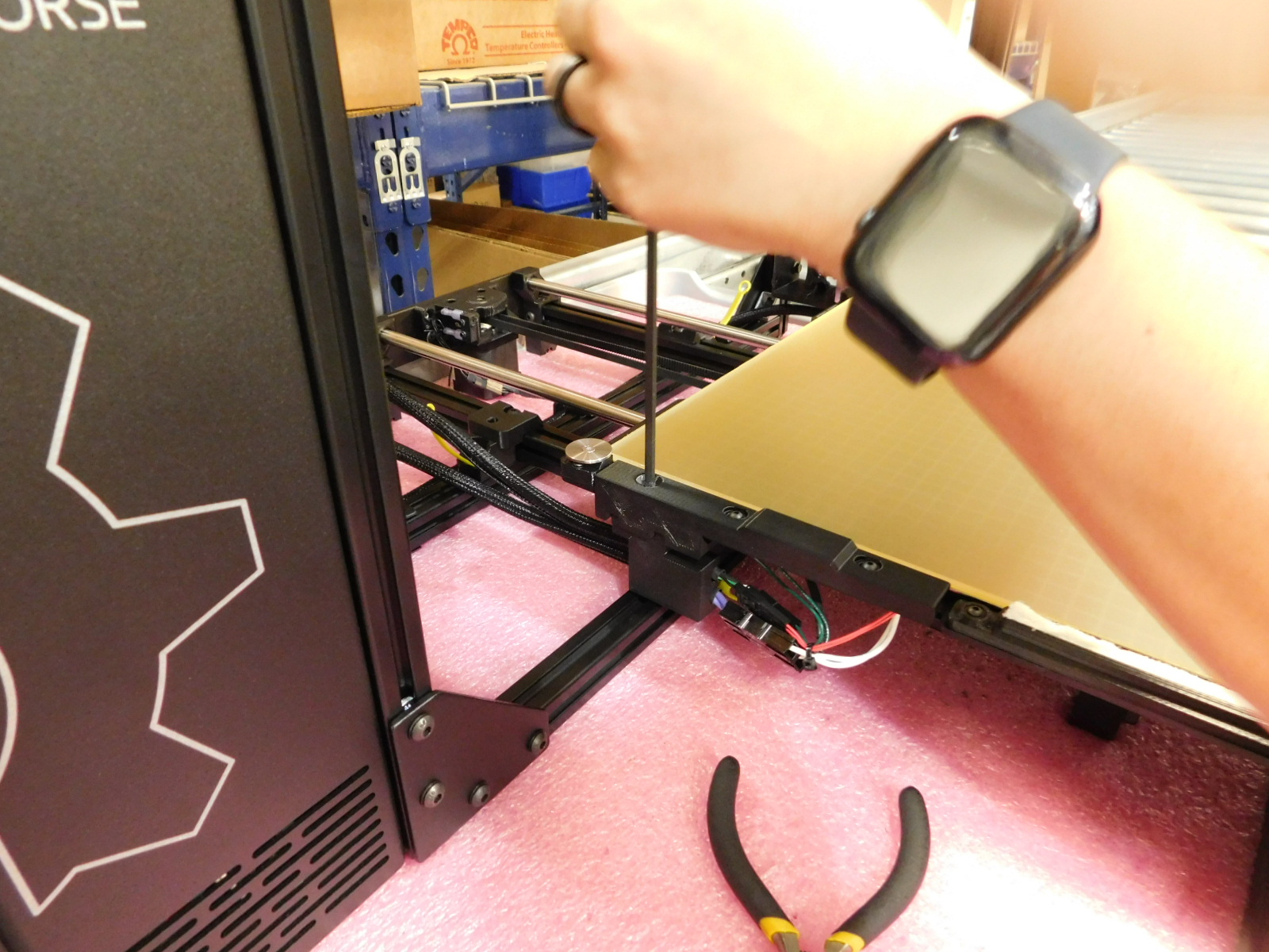
Using a 4mm Ball-tipped Hex Driver through the hole in the Y-Cable Cover and Bed Plate, loosen the M5 fastener securing the Y-Cable Mount to the Y-Cable Cover. Continue to turn counter-clockwise until the cable chain is free from the bed.
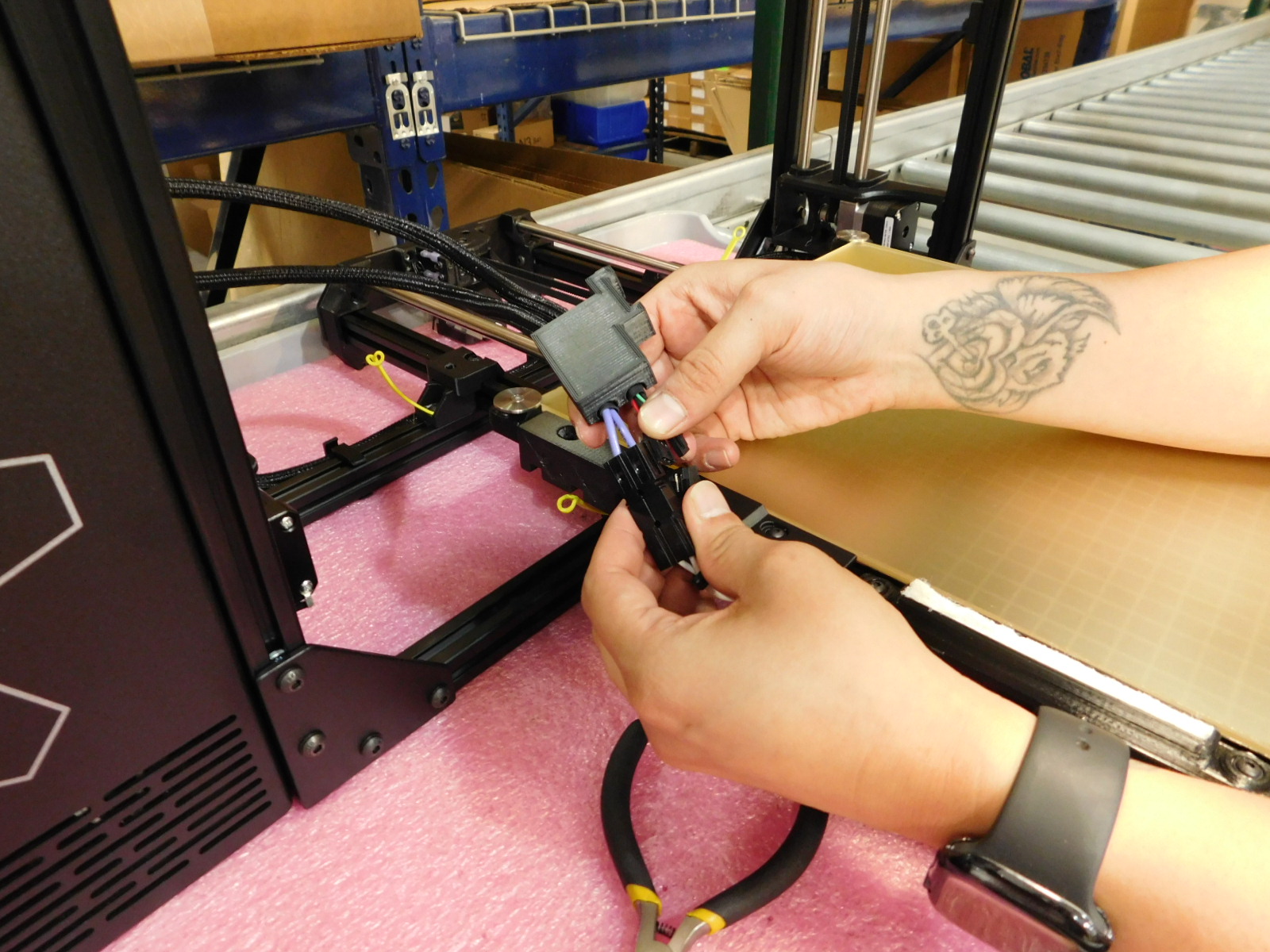
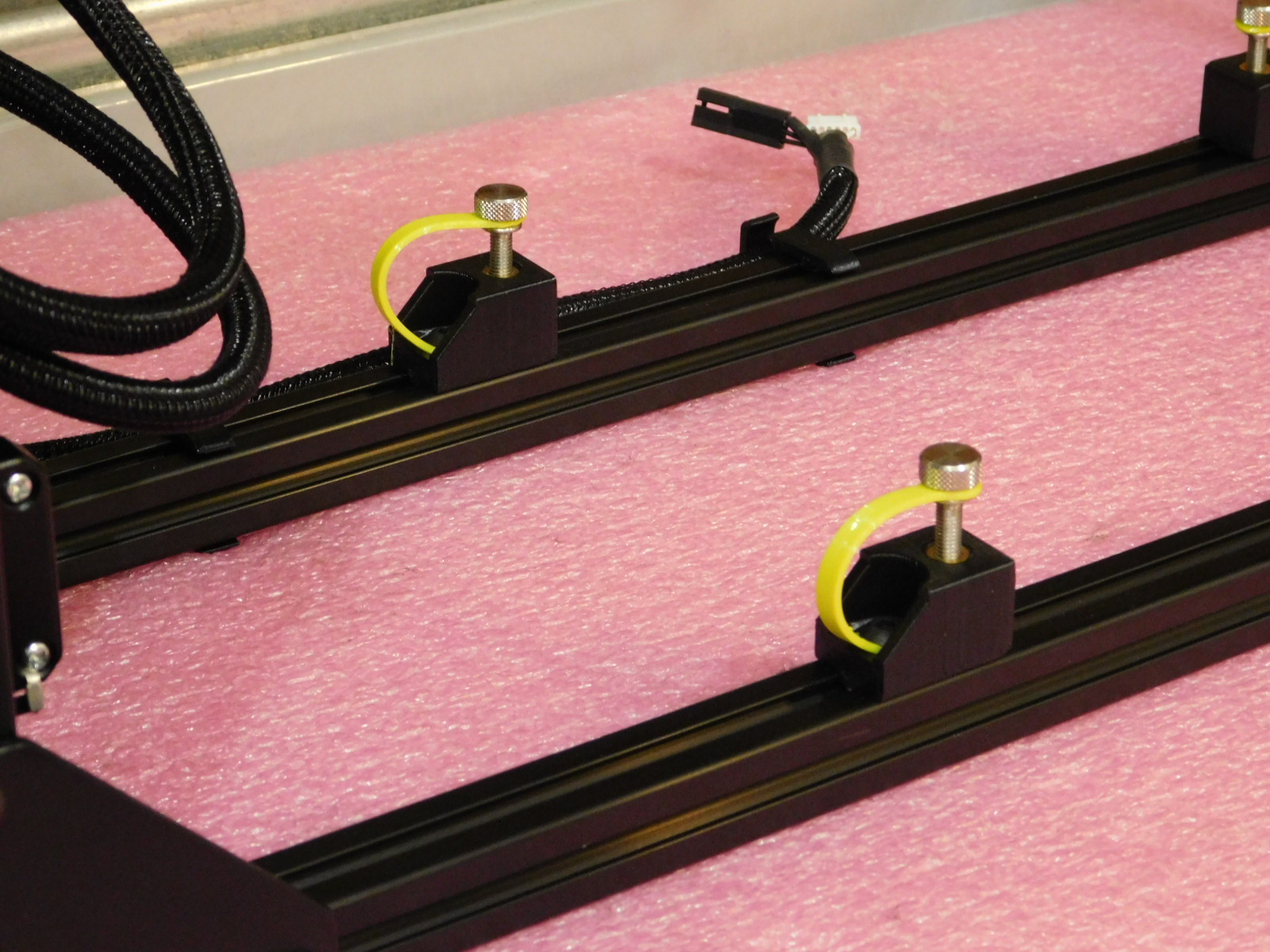
Disconnect all 3 connectors at the bed end of the Bed Harness, bed heat, thermistor, and ground.
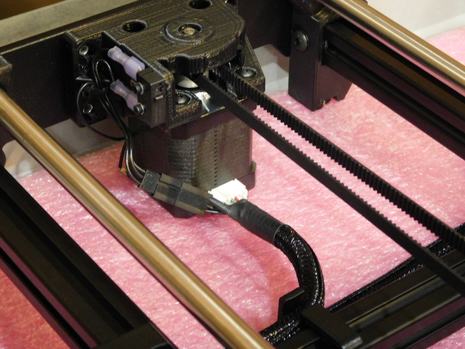
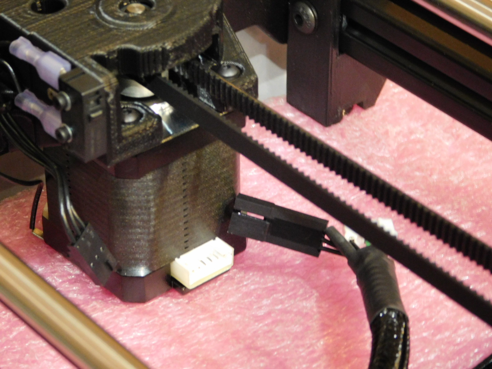
Disconnect both connectors at the Y-Axis Motor.
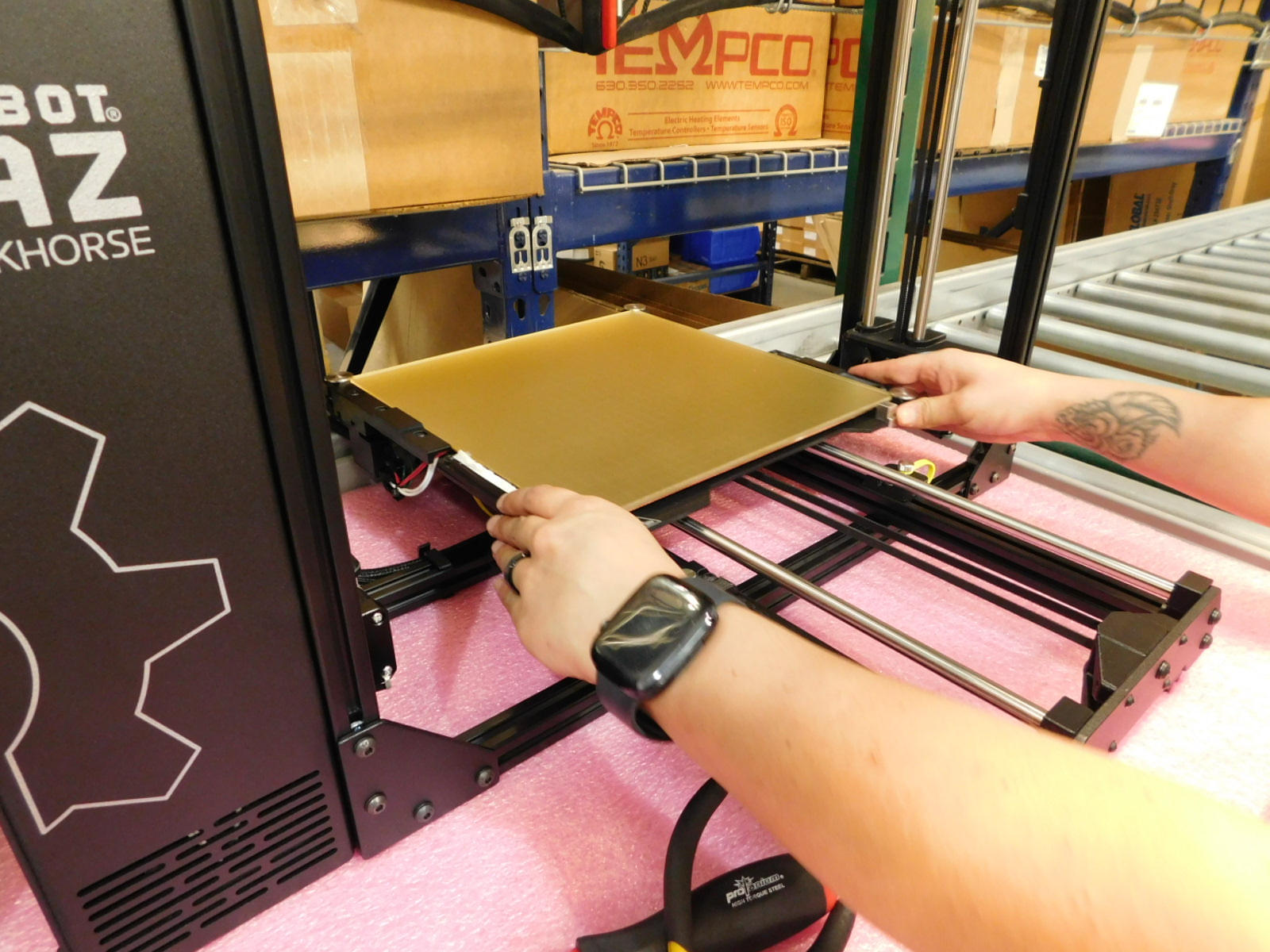
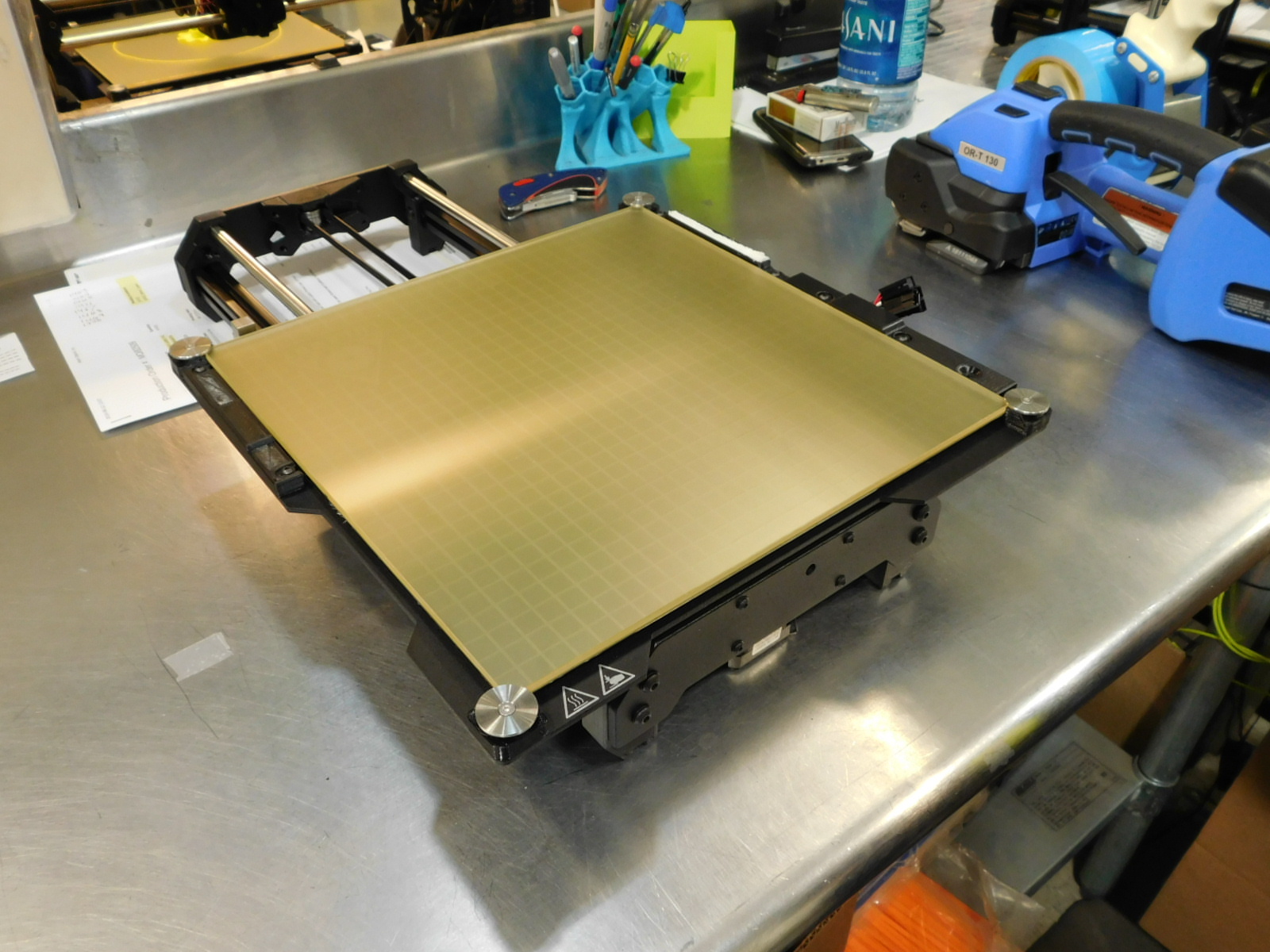
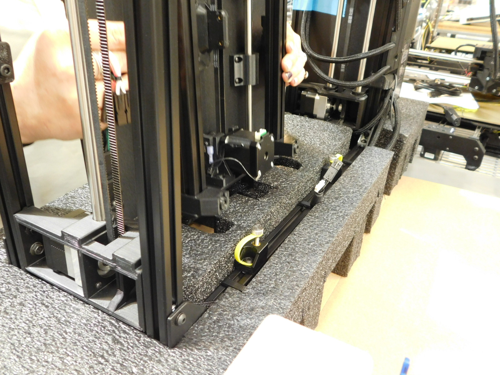
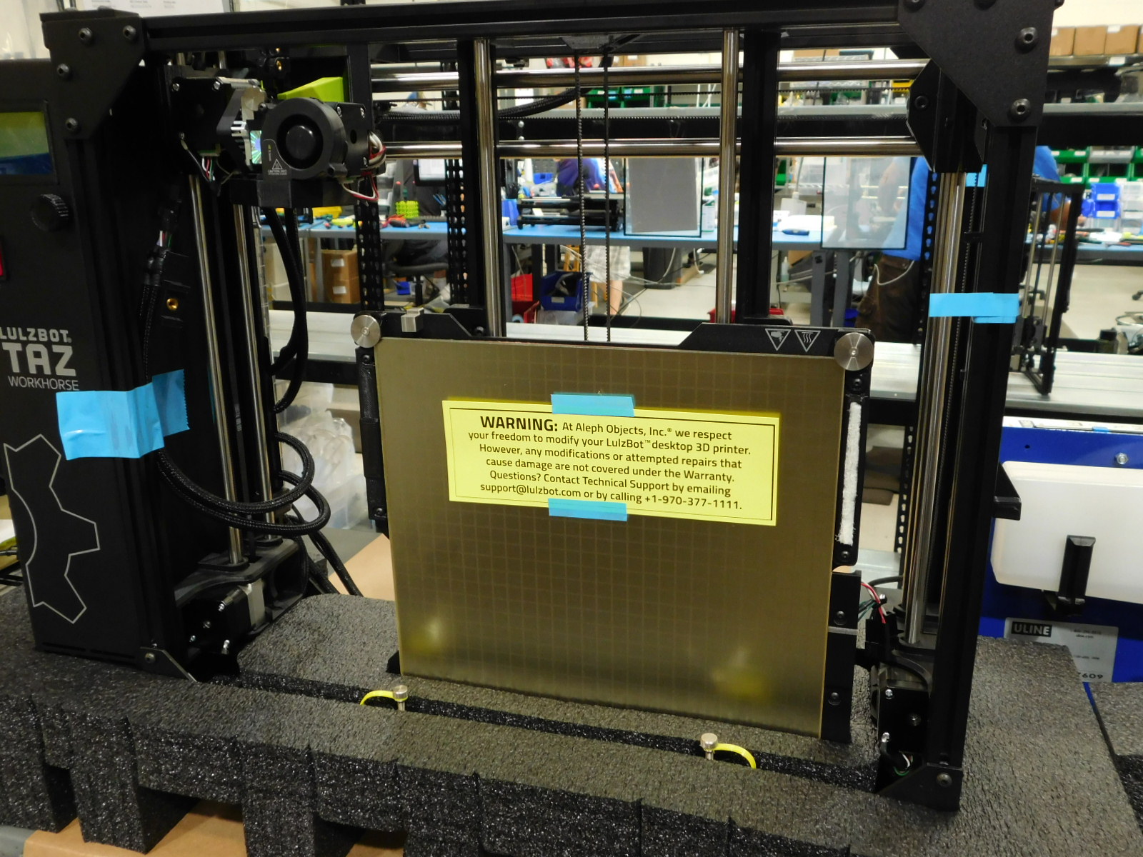
Lift the Y-Axis from the frame and place it to the side. Turn it around so that the motor is close to you and slide the bed plate flush with the end of the Y-Axis frame. This is the position it will be placed in the foam later.
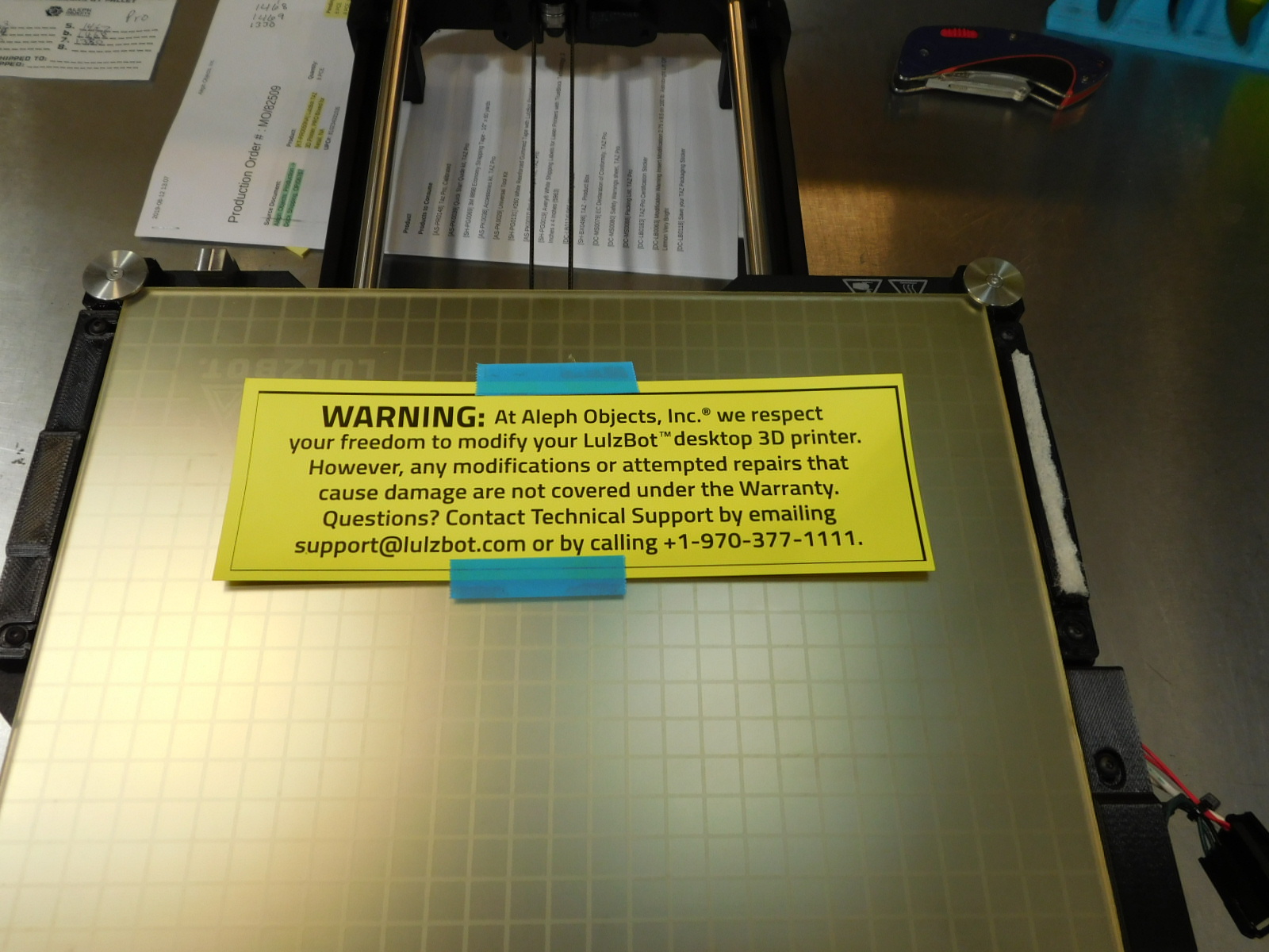
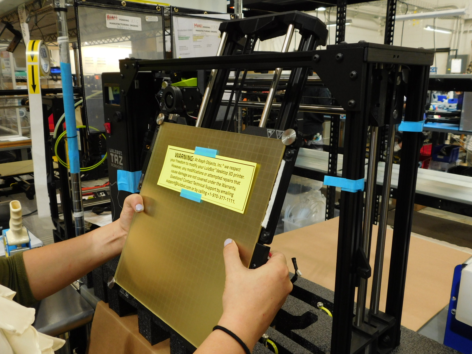
Use two short sections of blue strapping tape to secure one Modification Warning Insert [DC-LB0063] to the bed plate as pictured.
Re-install the M5 thumb screws into the chassis mounts, finger tight so that they do not vibrate loose during shipping.
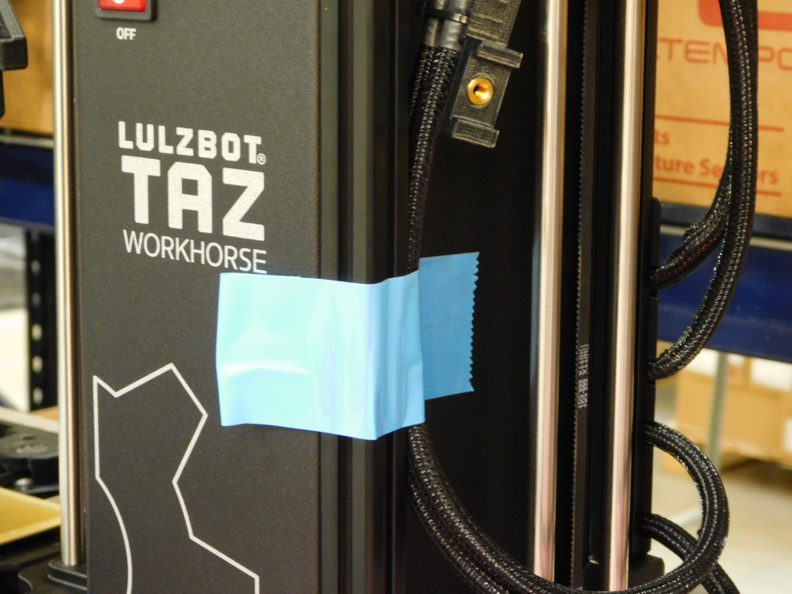
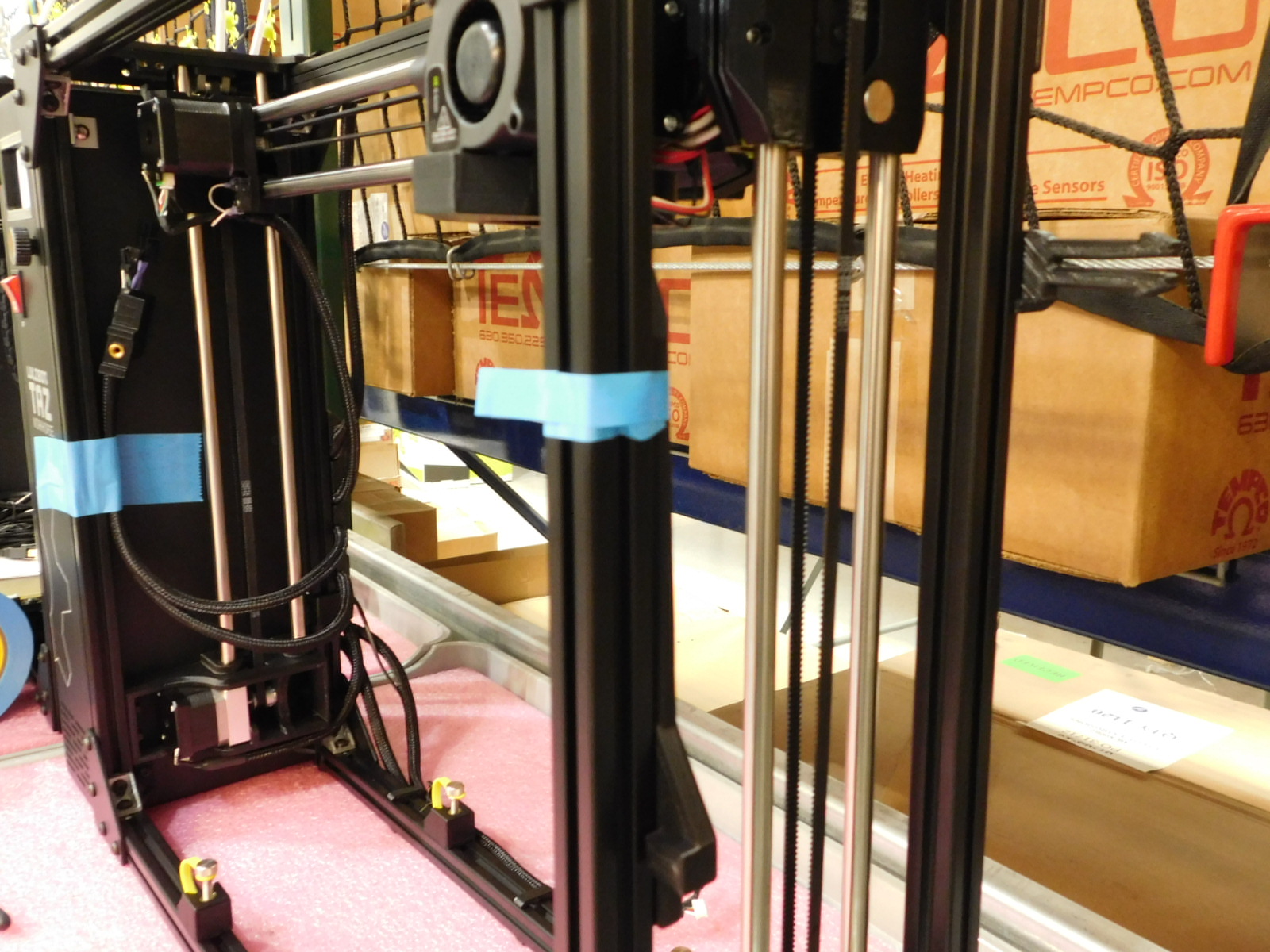
Add a piece of wide blue strapping tape to secure the Y-Bed Harness to the right side of the control box, as pictured. Make sure to make a little tab on the tape so that it can be easily removed by the customer.
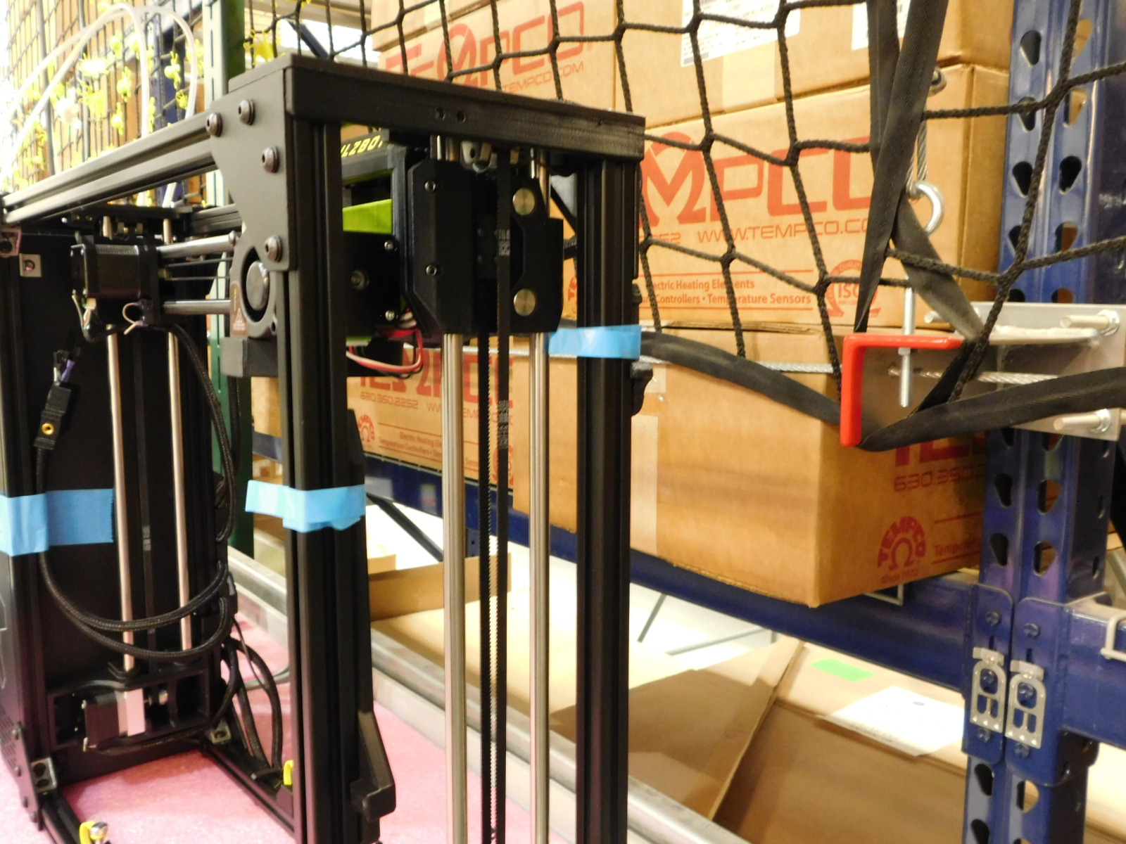
Add a piece of narrow blue strapping tape to the spool arm and the feed tube holder to hold them in place. The tape only needs to be long enough to wrap around the spool arm 1.5 times. Make sure to make a little tab on the tape so that it can be easily removed by the customer.
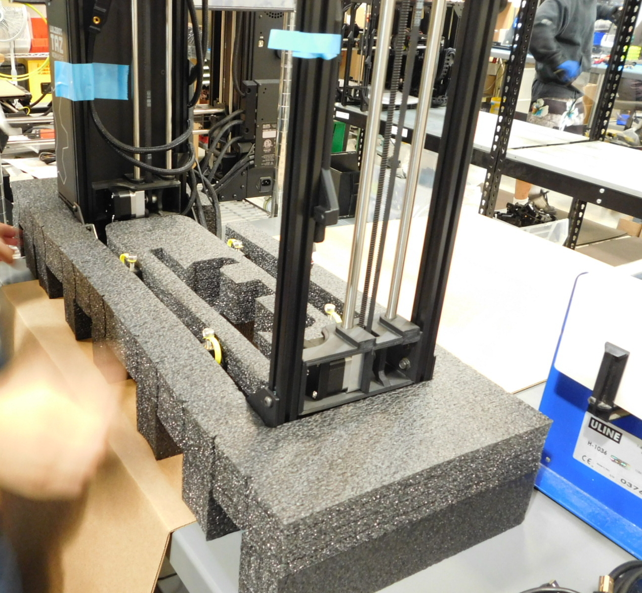
Carefully lift the printers frame and lower it into the Bottom Endcap Foam prepared in step 8.
Carefully pick up the Y-Axis, grabbing both the bed plate and the frame below.
Angle the top (idler end) away from you and carefully slide it between the top front frame rail of the printer and the X-Axis smooth rods, as pictured.
Pivot the bottom (motor end) into place and press the Y-Axis down into the bottom endcap foam as pictured.

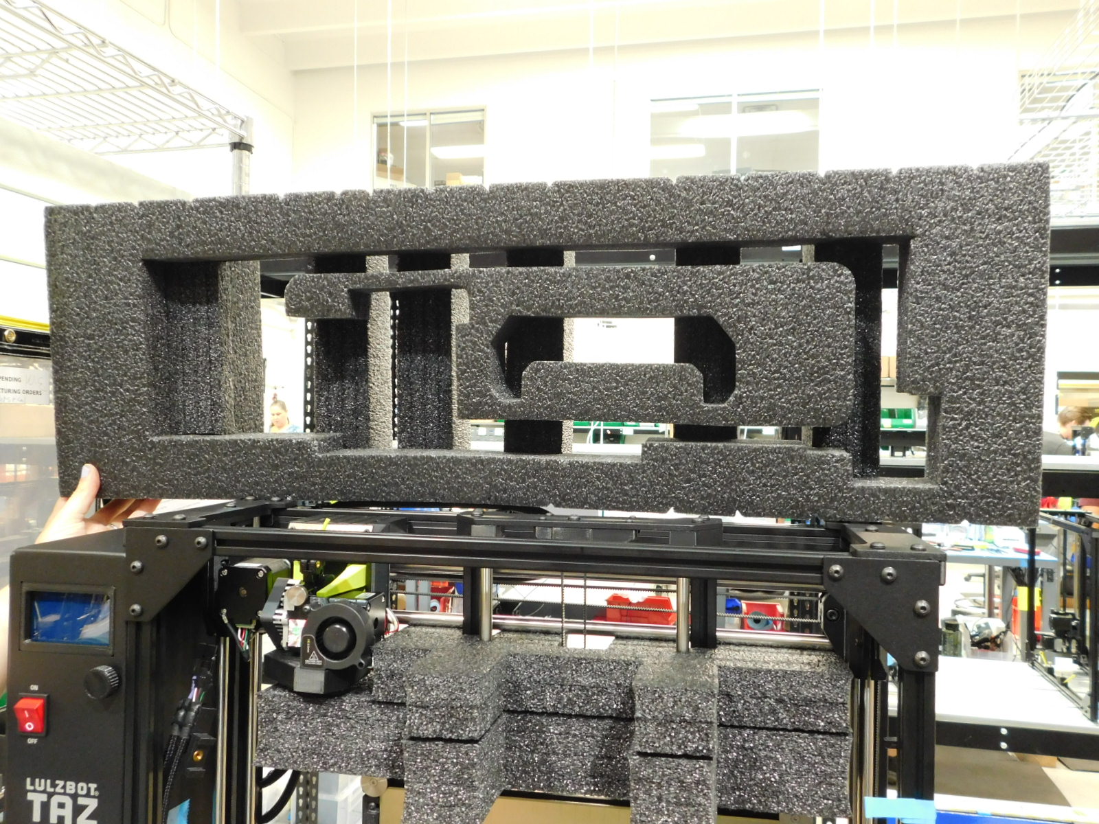
Place the two middle pieces around the y-axis. This will support both the tool head and the x-axis.
First place the larger piece [SH-PA0068] then place the smaller piece [SH-PA0067] on top of that.


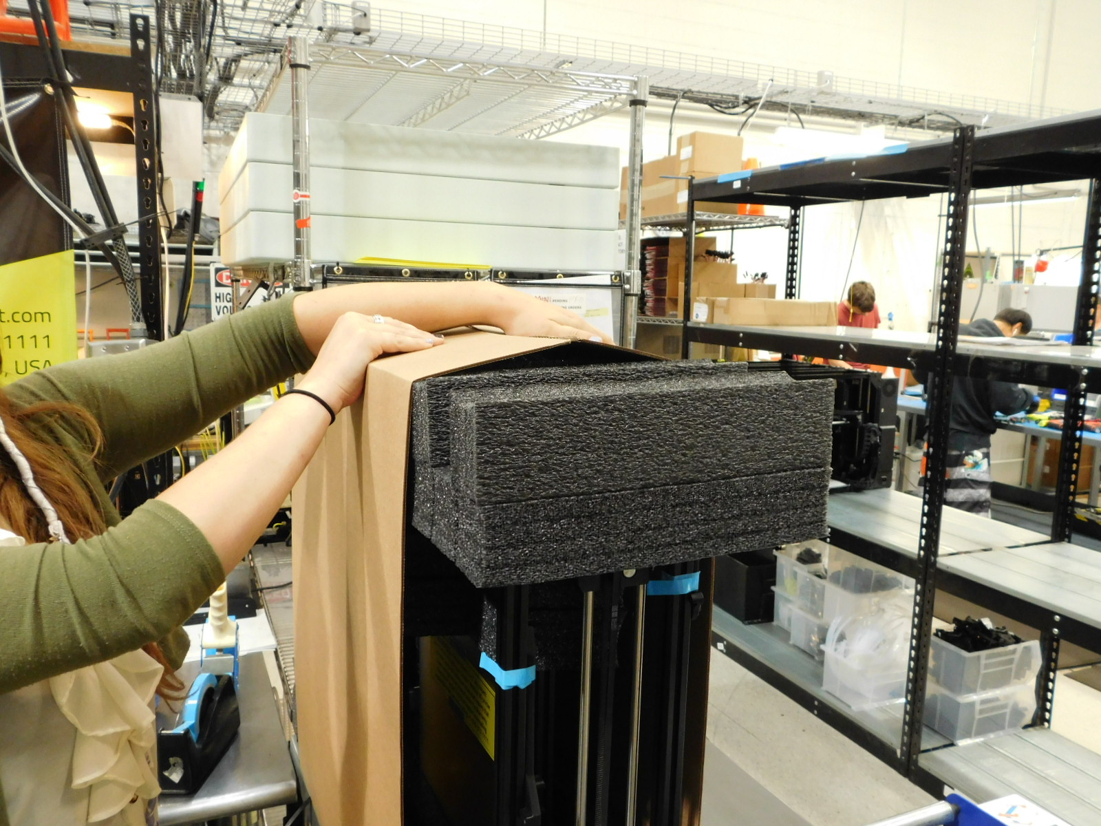
Add the top piece of foam [AS-PA0060] to the printer.
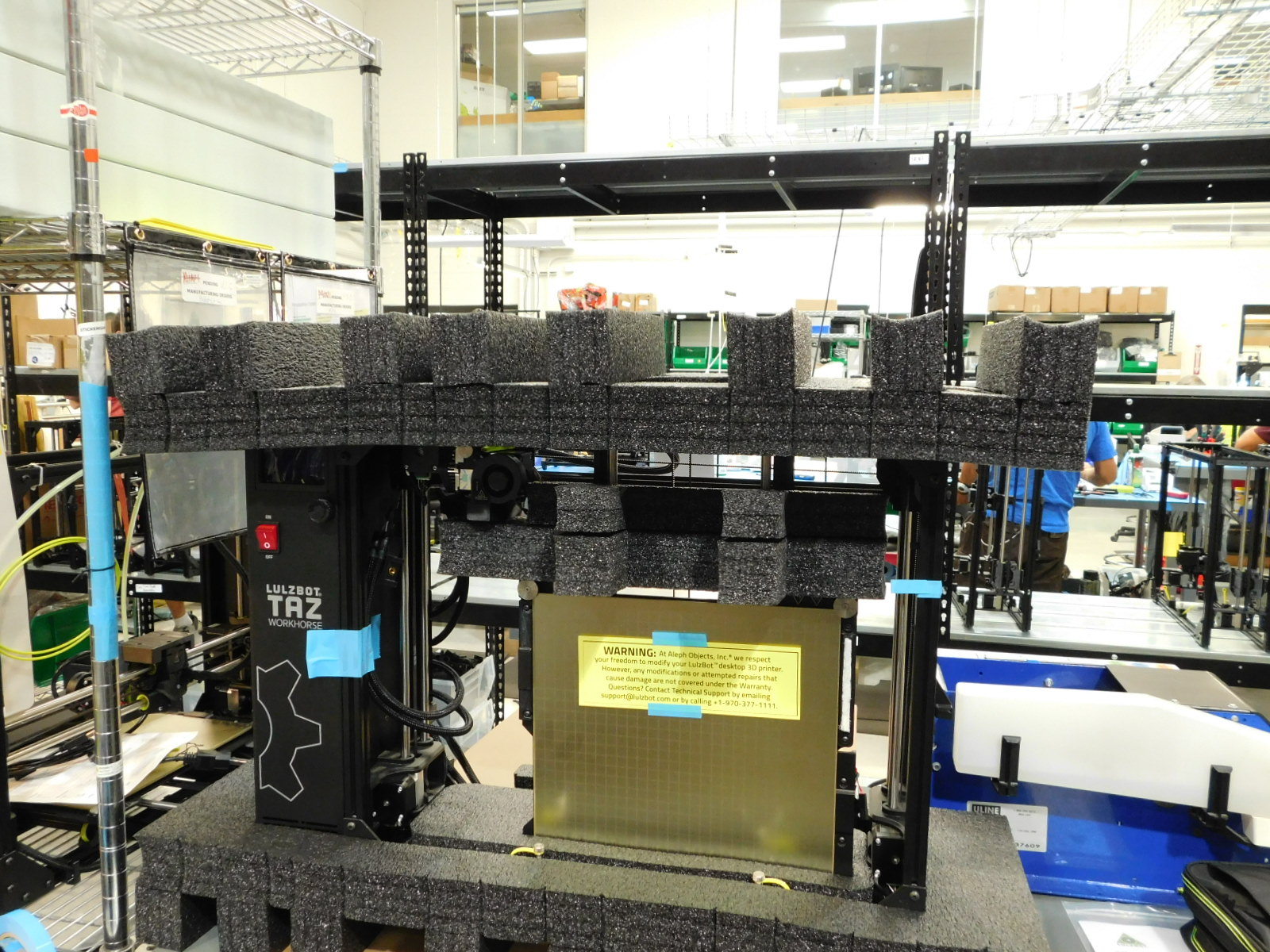
Add the tool kit, cables, and document bag in the top piece of foam.
Fold the Corrugate Sleeve up around the printer.
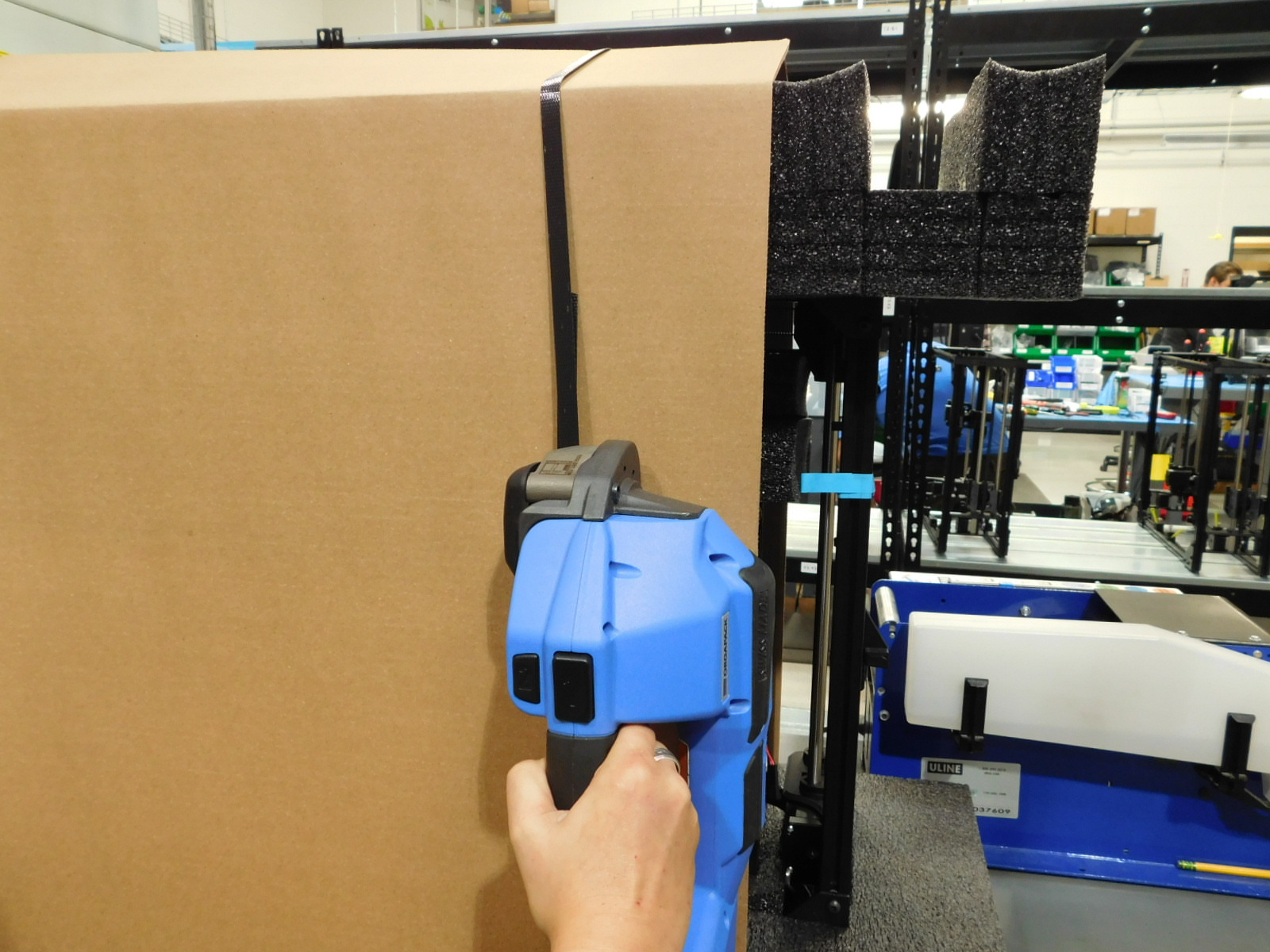
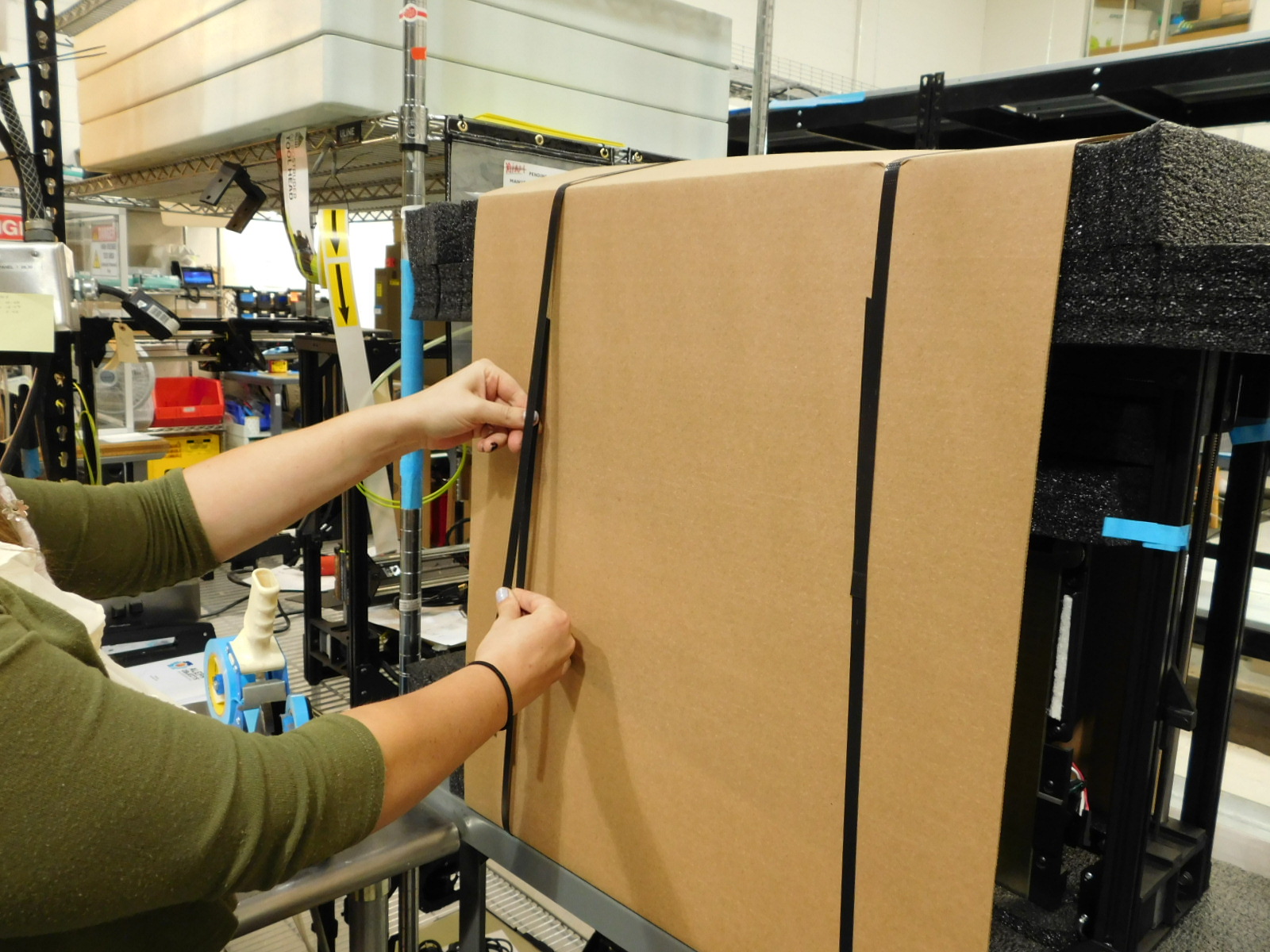
Pull the right-hand side strap up and around the printer and align the straps ends with the top laying over the bottom end and hold with your left hand.
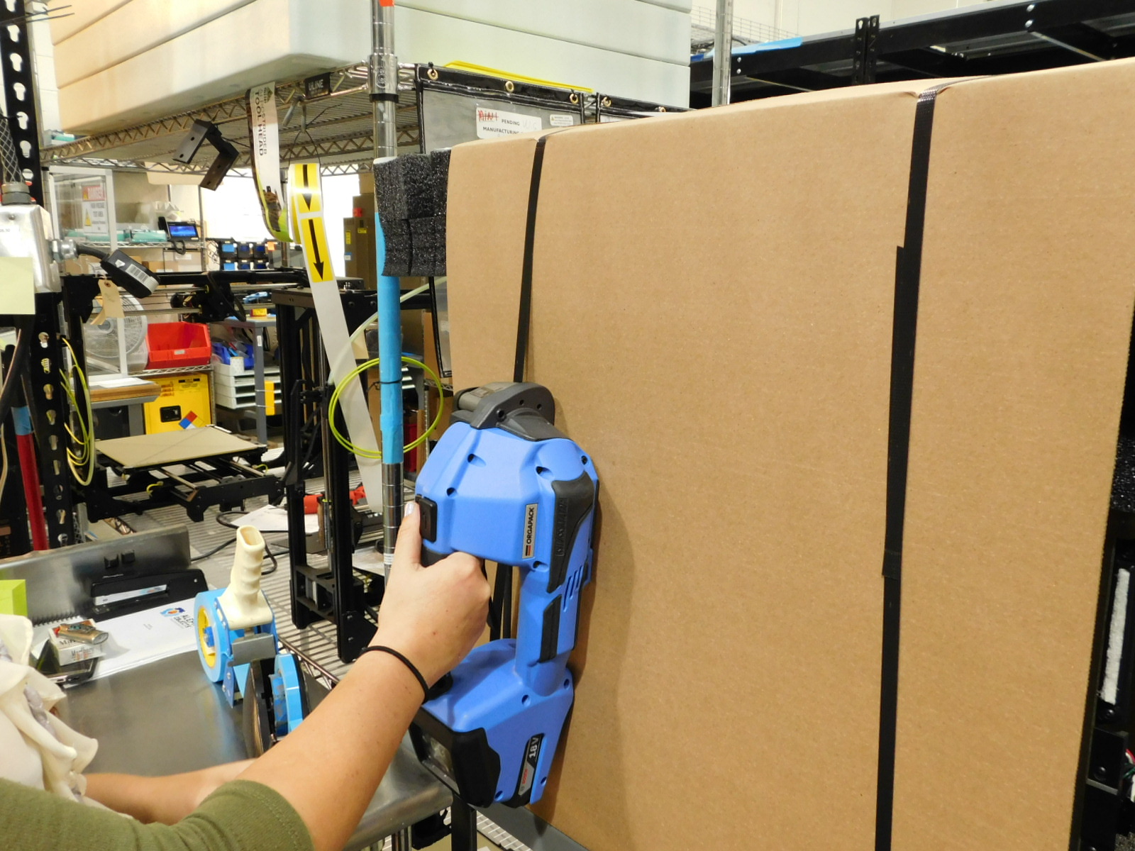
Grab the strapping tool with your right hand and pull the lever to open the latch
Place the strapping tool over both strap ends and ensure both remain aligned with each other; release the lever of the strapping tool.
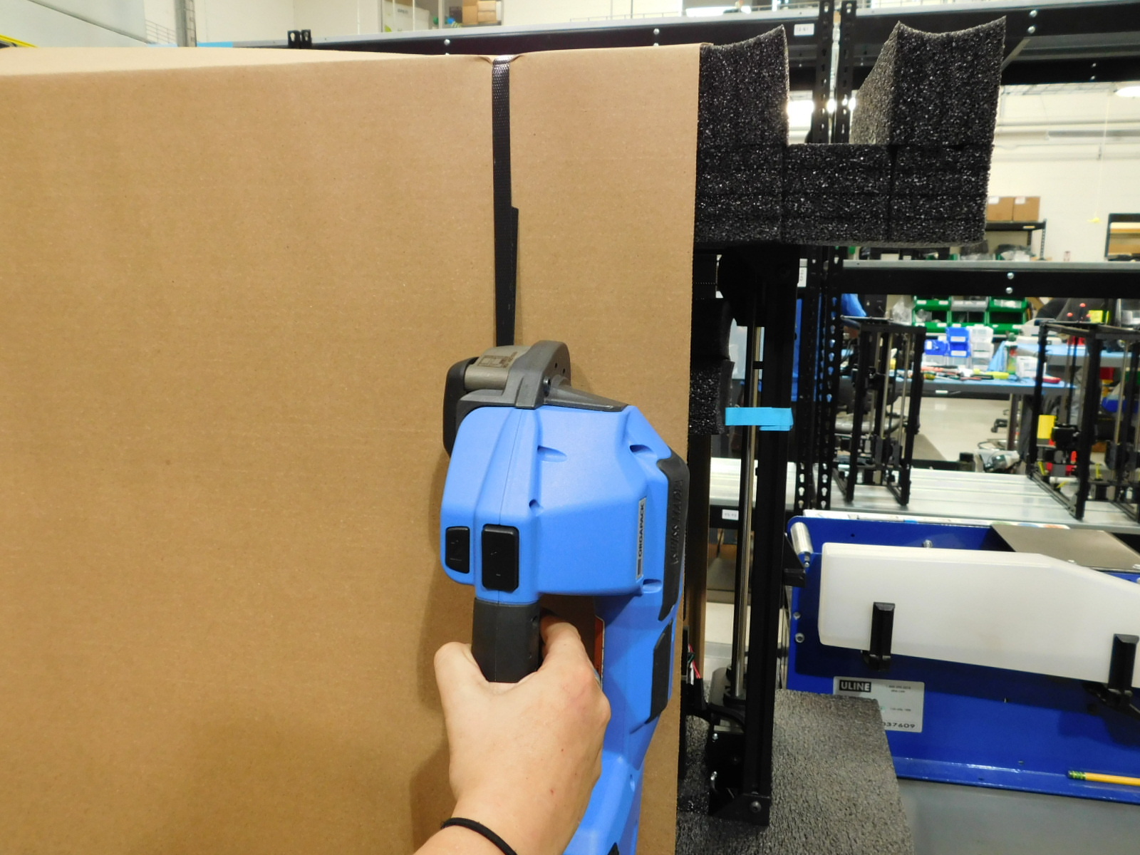
Press and hold the "1" button to tighten the strap and then press the "2" button to seal the straps together.
Pull the lever to release the strapping tool and slide it out to your right.
Repeat for the left-hand side strap.


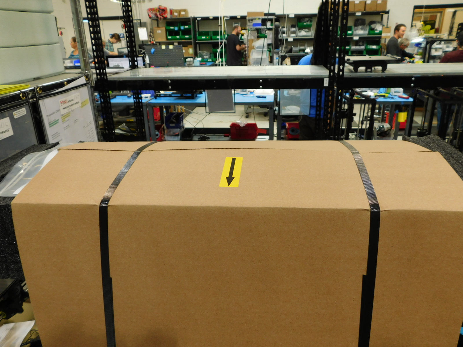
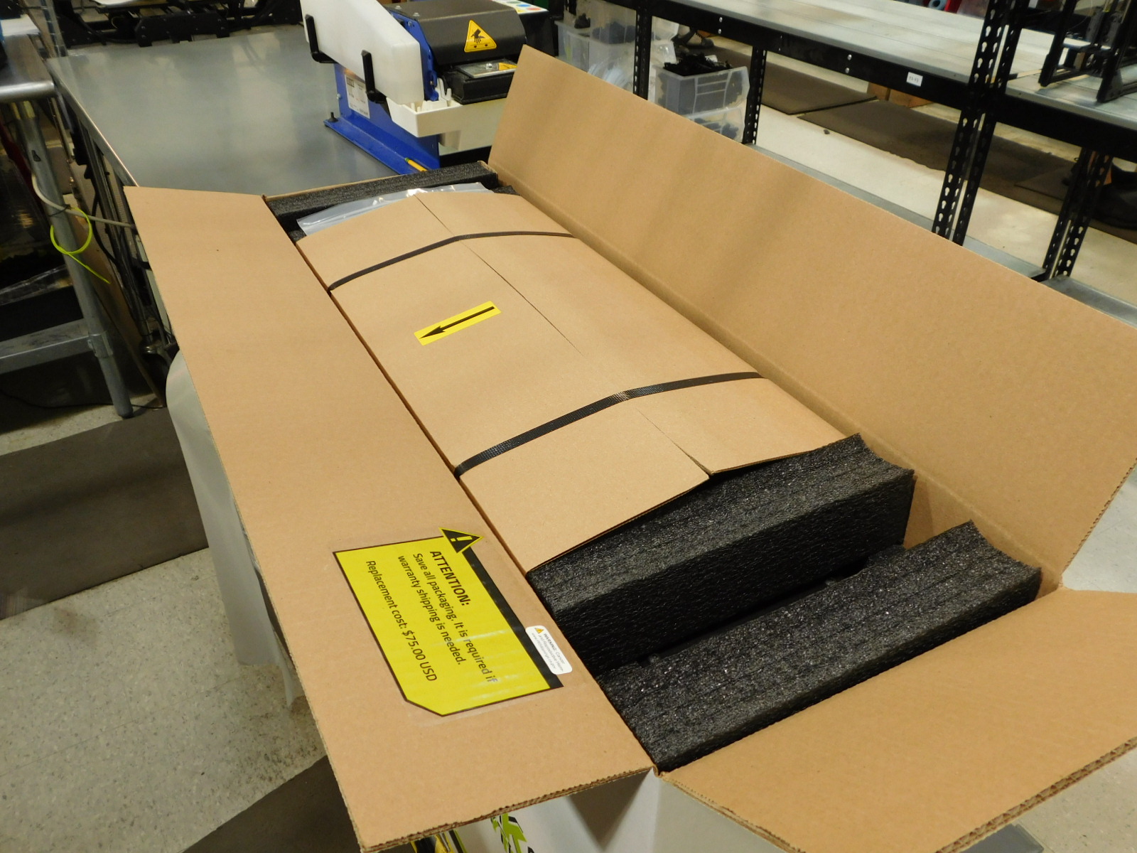
Apply one Arrow Sticker [DC-LB0105] to the top front of the cardboard in the middle with the arrow pointing towards you, as pictured.
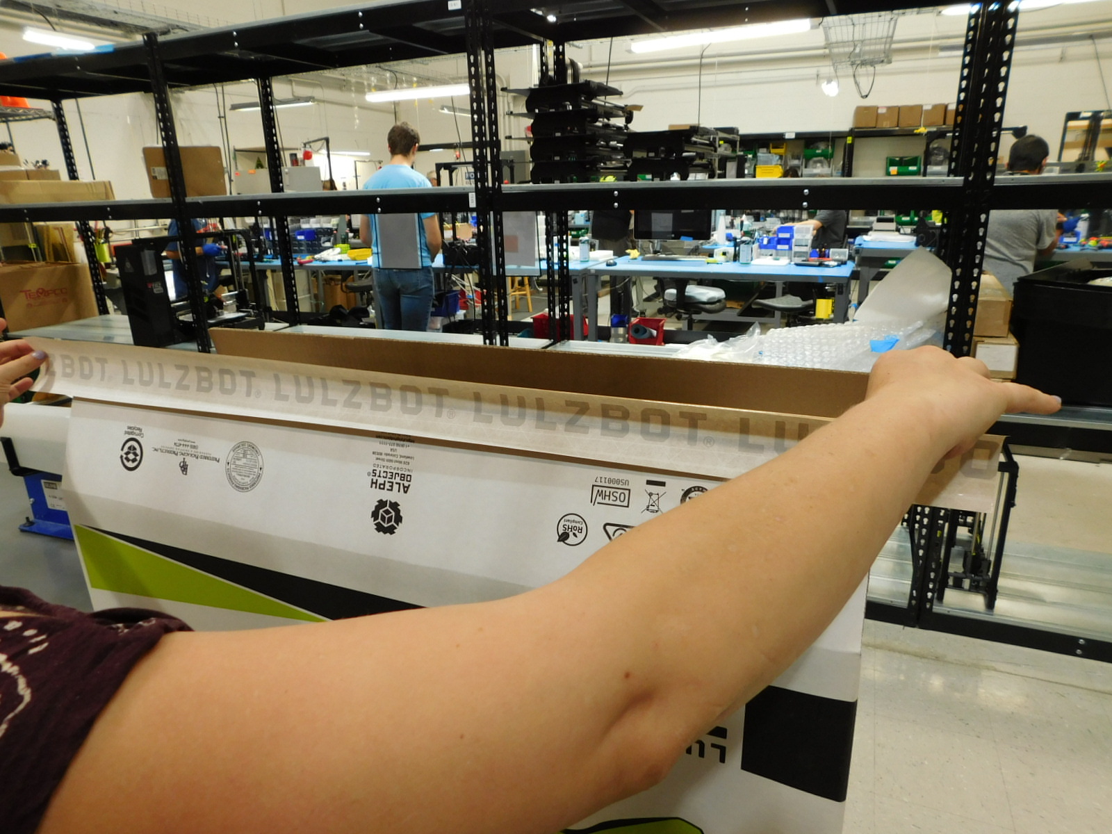
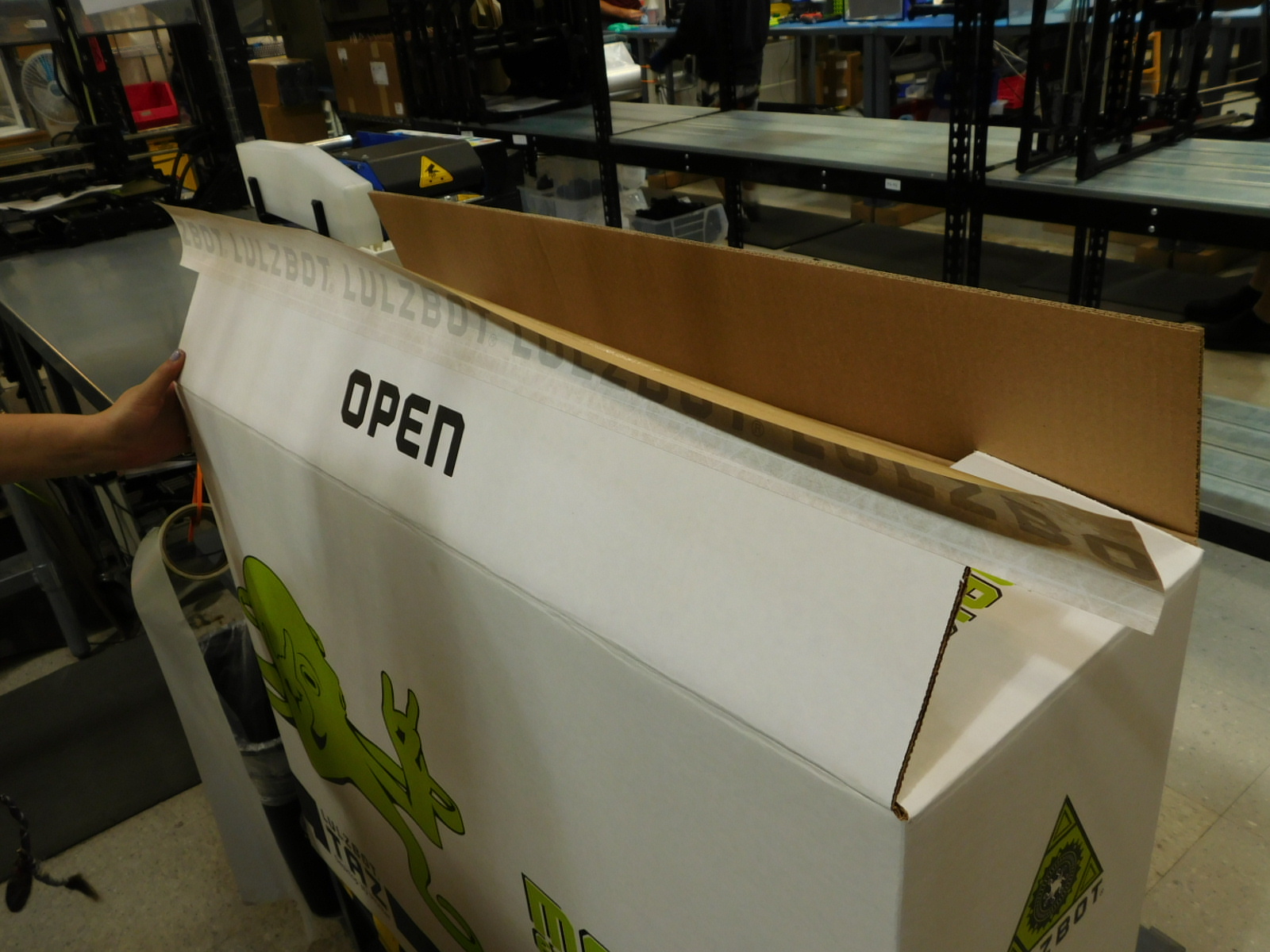
Obtain one TAZ Shipping Box [SH-BX0498]
Fold the bottom of the box, first the smaller flaps, then the larger ones.
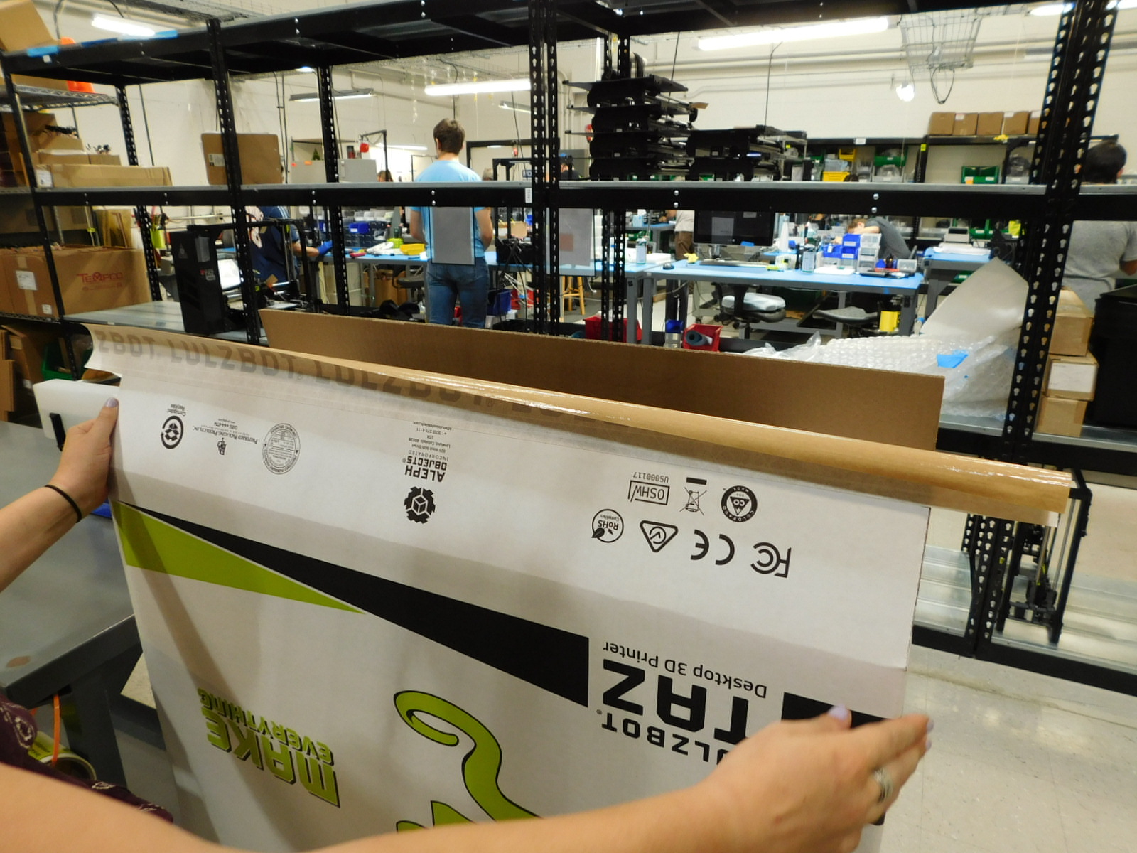
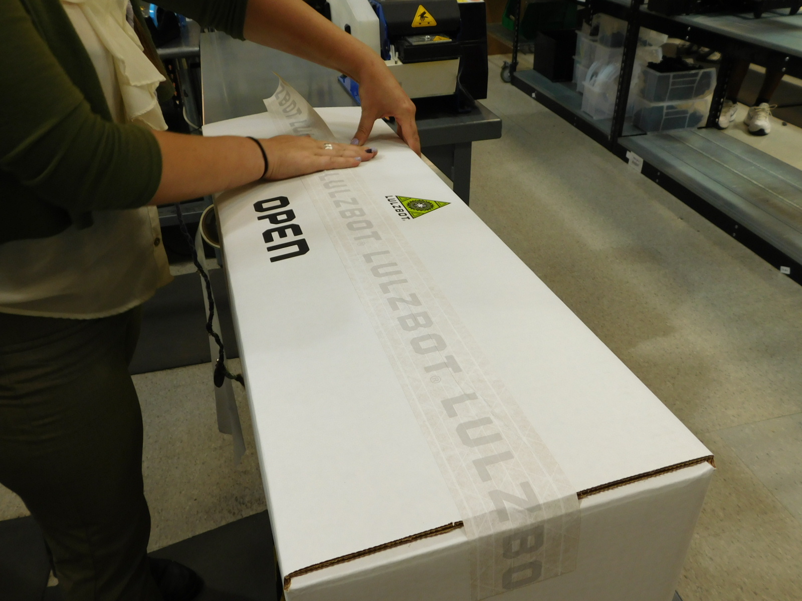
Obtain one 40 inch length of Lulzbot Reinforced Gummed Tape [SH-PG0131] from the tape dispenser and place it centered along one of the long flap edges. Fold the box and press the tape flat to the box.
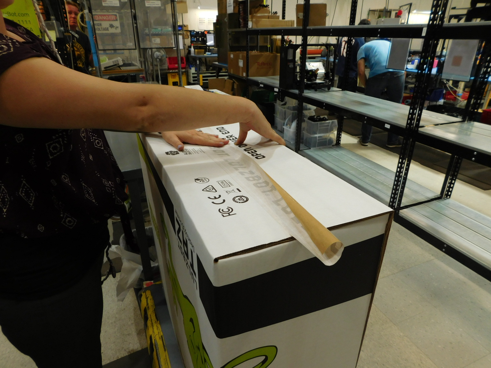
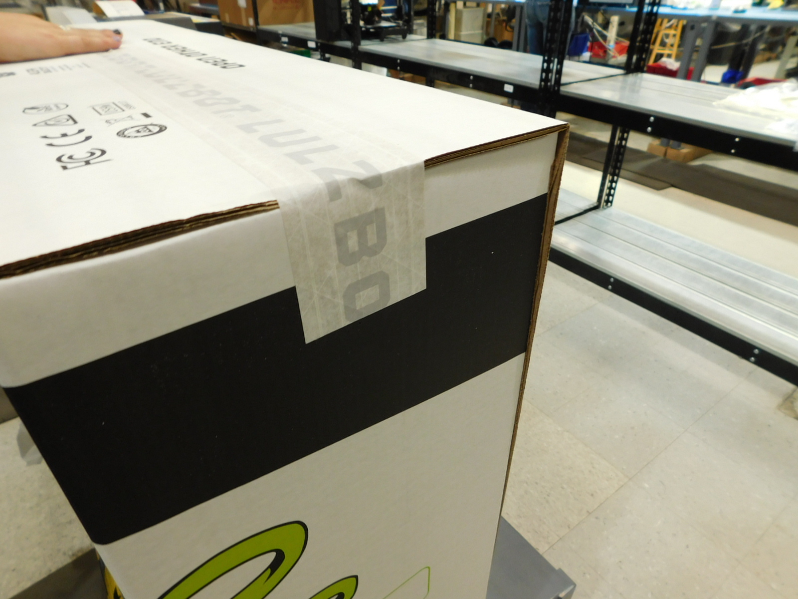
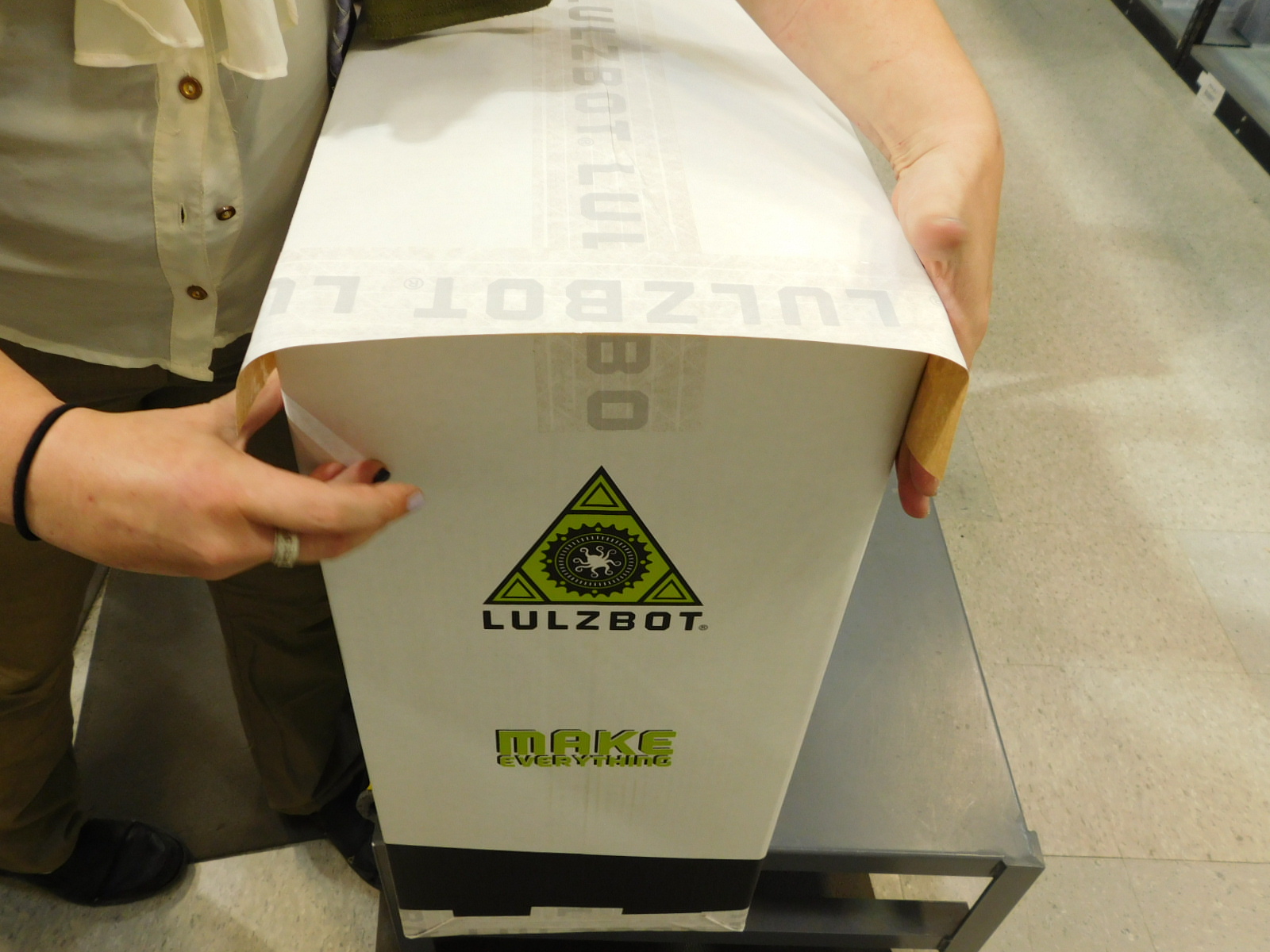
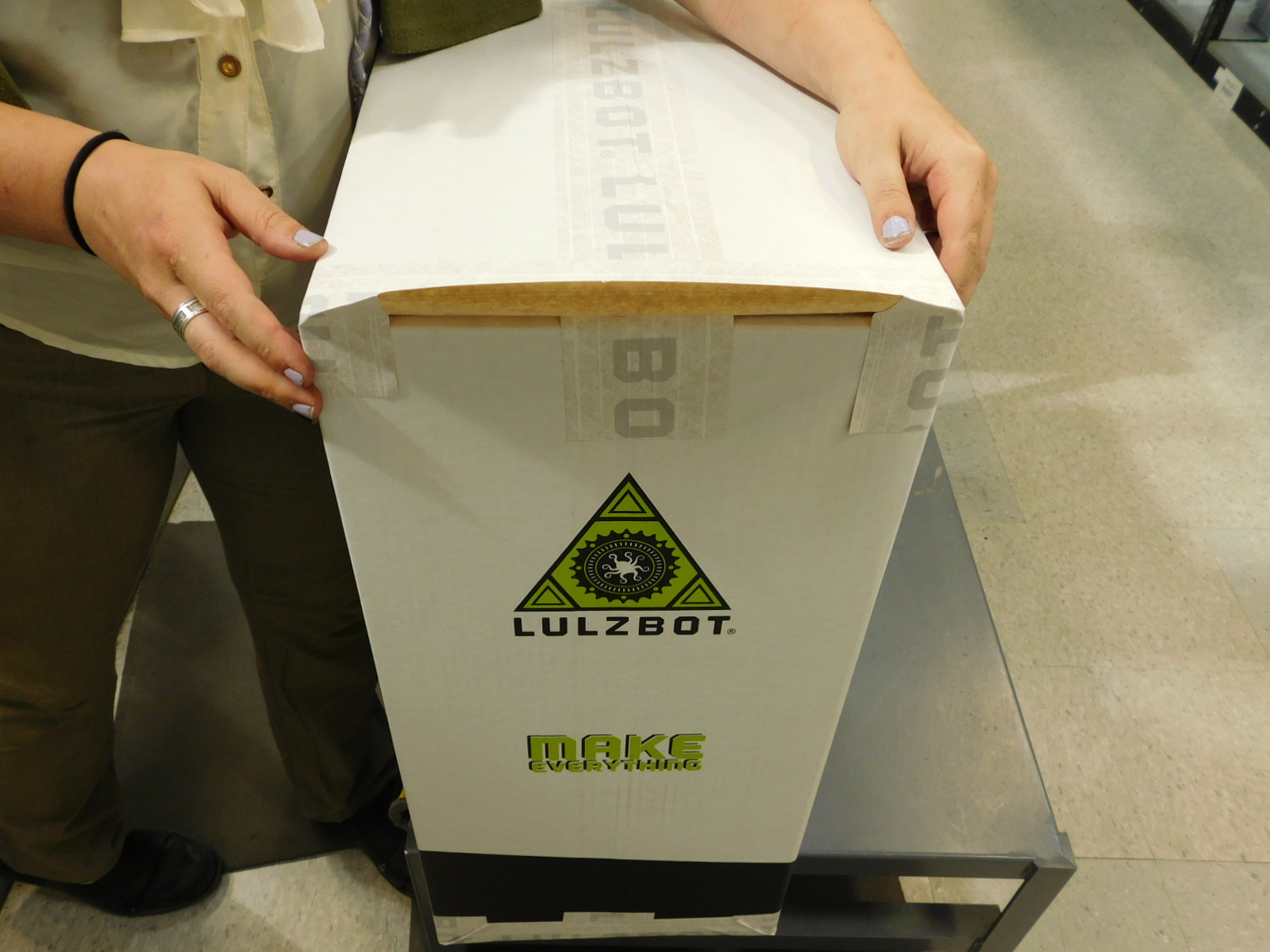
Obtain one 16 inch length of Lulzbot Reinforced Gummed Tape [SH-PG0131] from the tape dispenser and use it to cover the short box edge by placing it center over that edge, pressed flat on the bottom of the box. Then press the tape down over the long sides of the box, in towards the short side, and fold the lip of the tape down flat. Press firmly.
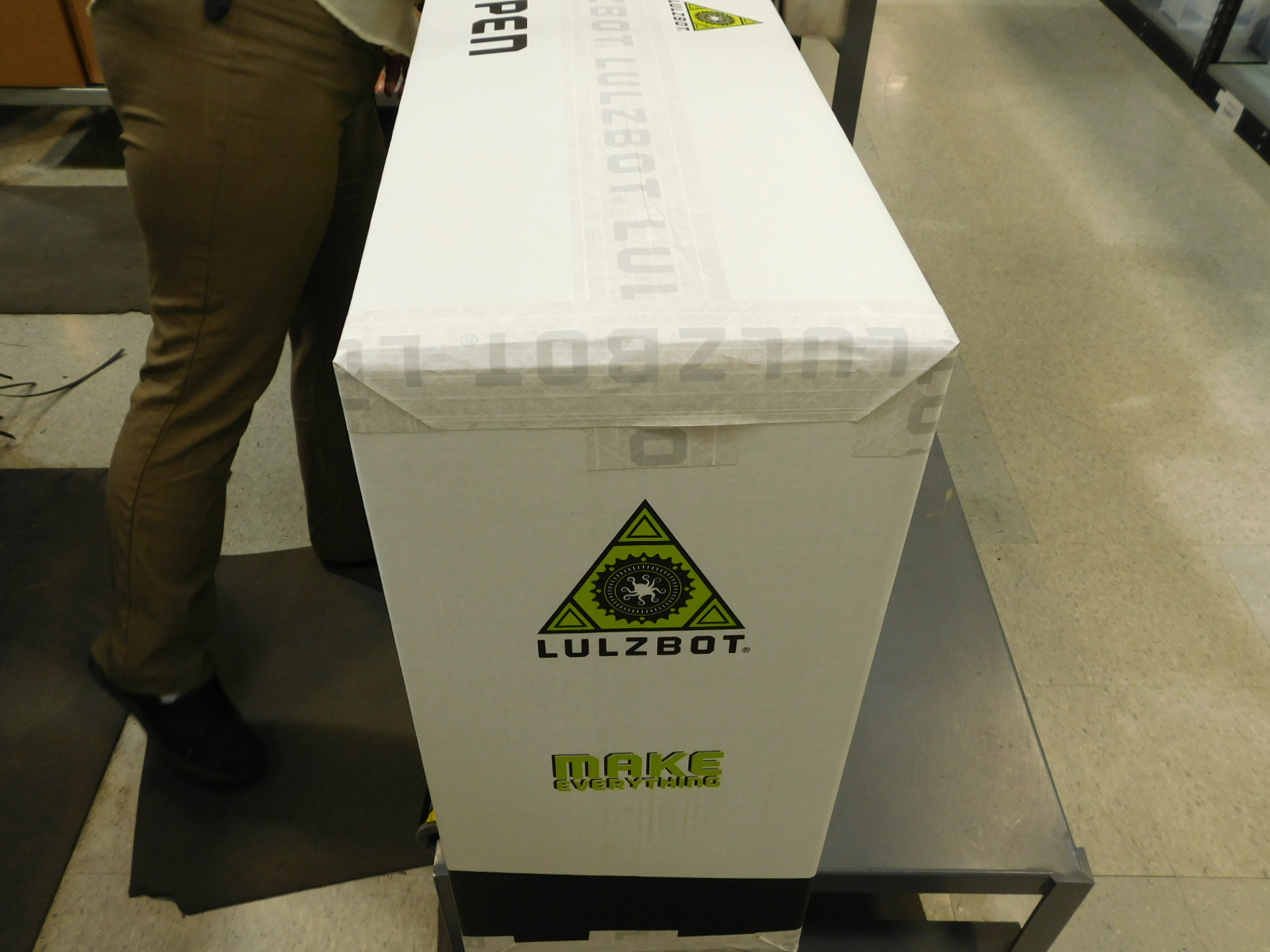
Repeat this process for the other short bottom box edge.
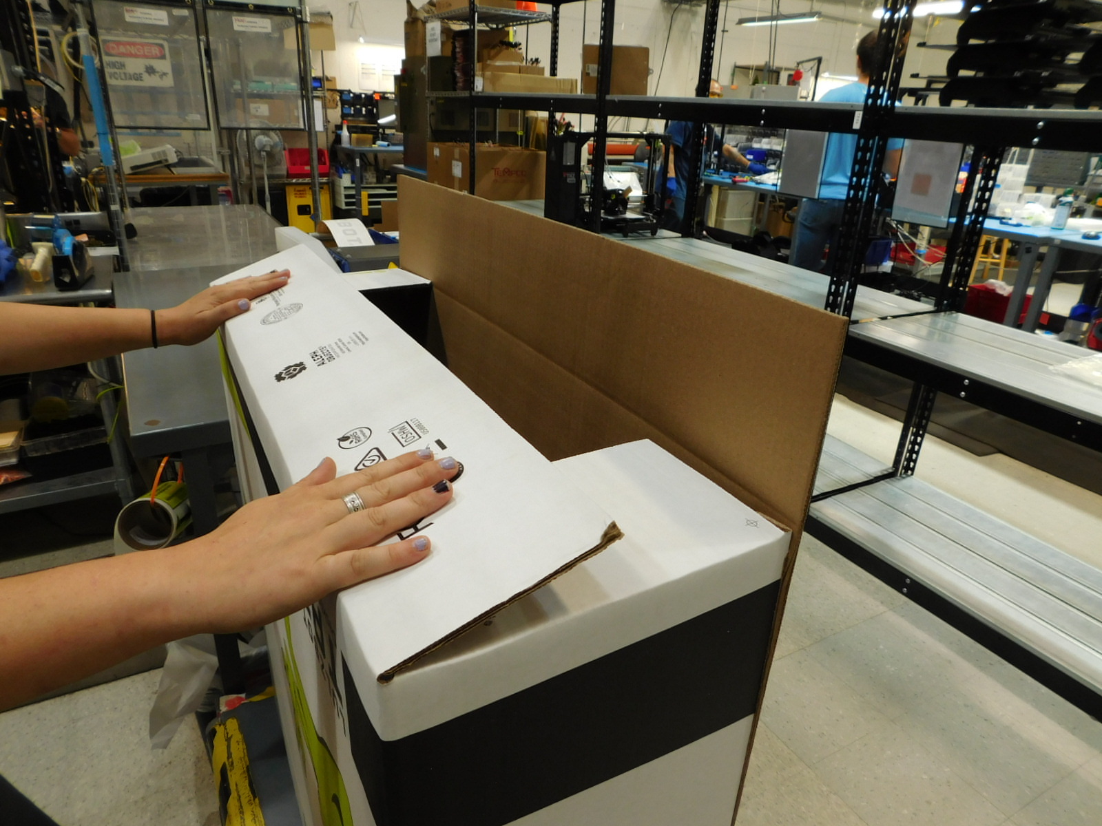
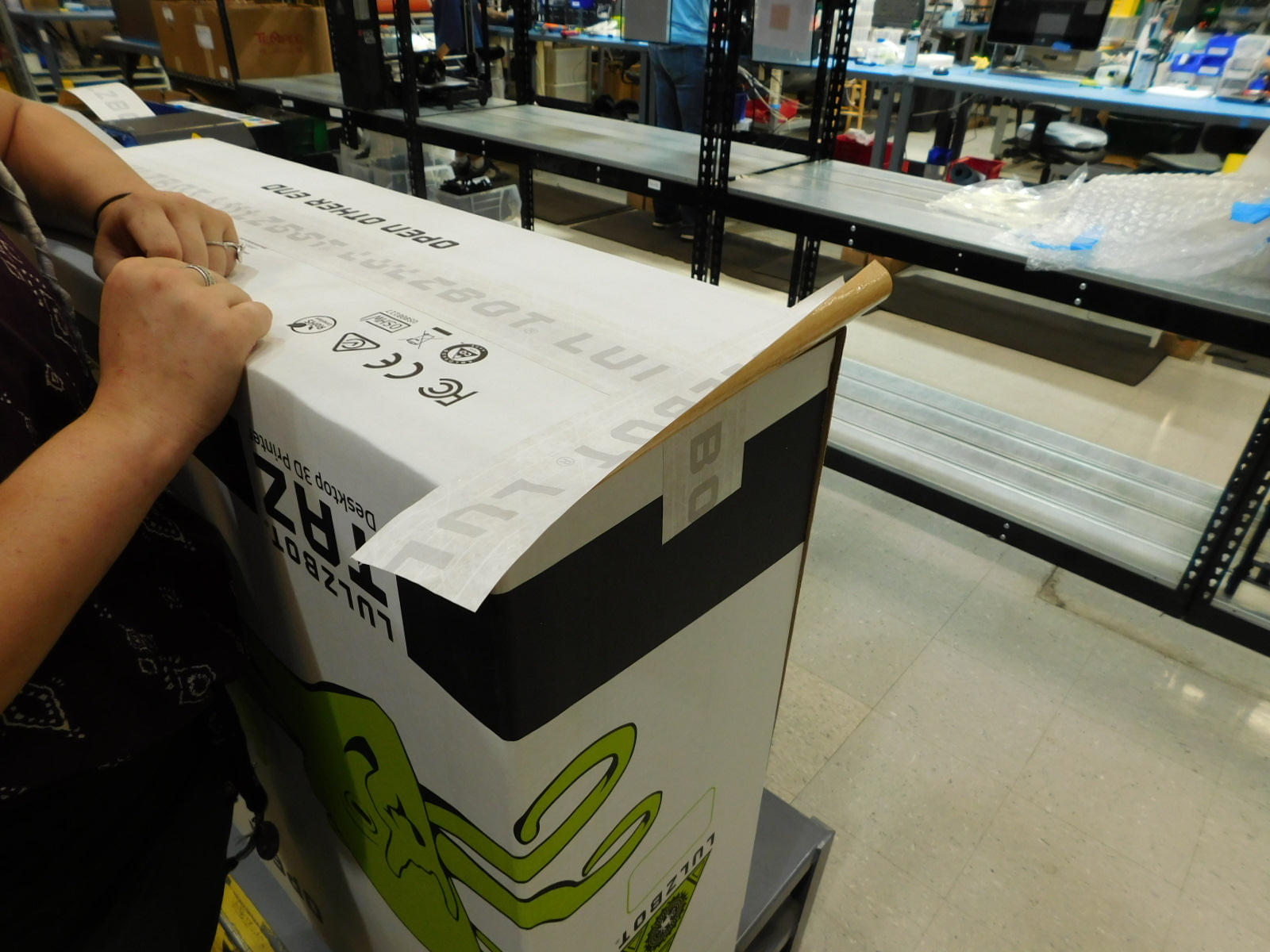
Flip the box upright and fold all four top flaps outwards.
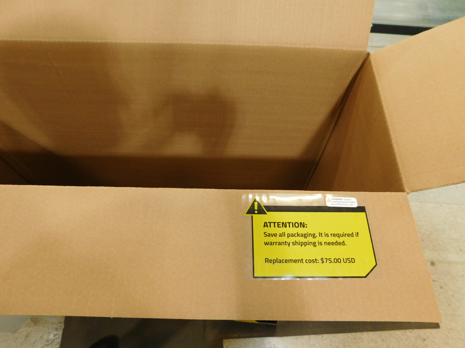
Affix one Save Your Packaging Sticker [DC-LB0118] to the inside of the front top large box flap.
Apply one P65 Warning Label [DC-LB0174] to the top of the Save Your Packaging Sticker, as pictured.


Rotate the box if necessary so that the outline for the printers serial number is to your left.
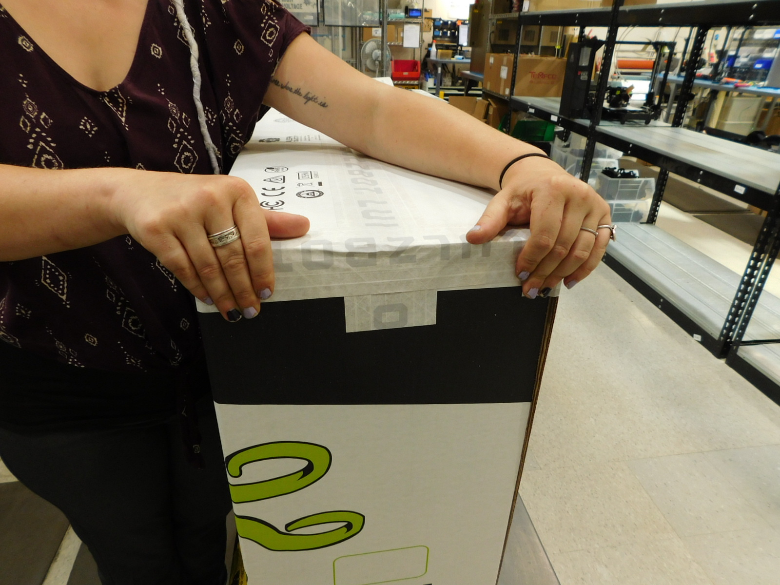
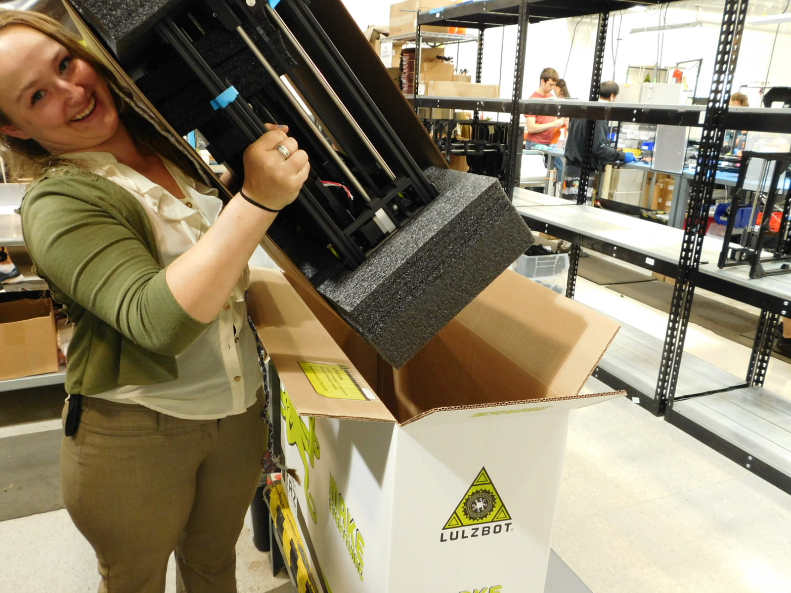
Pick up the printer by lifting via the straps at the top of the unit and lower it into the shipping box prepared in the previous step.
Obtain the Quick Start Guide Pack completed in step 5.
Place it on the side of the box with the outline for the printers serial number (should be to your left).
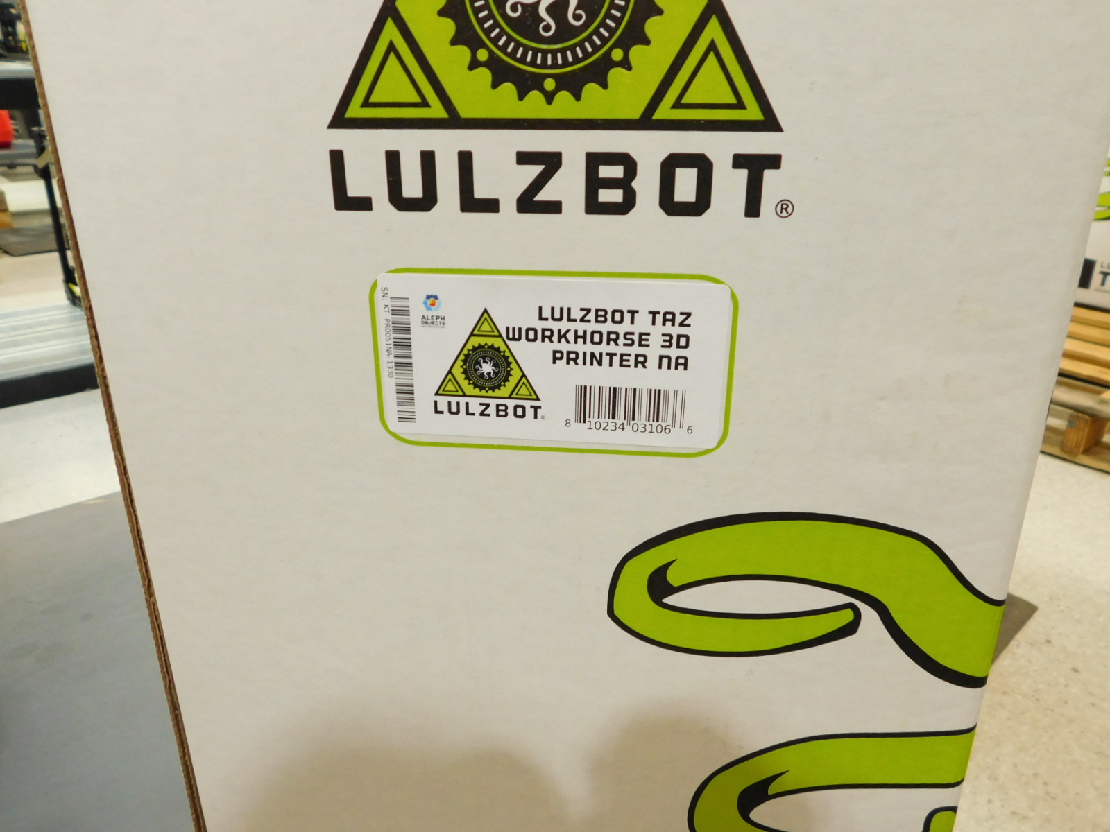
Locate the correct serial number label for the printer in the box.
Peel the label from the sheet and place it straight within the green outline on the box.
Fold all four top flaps of the box inwards beginning with the two smaller flaps.
Obtain one 40 inch length of Lulzbot Reinforced Gummed Tape [SH-PG0131] from the tape dispenser and place it centered along one of the long flap edges. Fold the flap down and press the tape flat to the other long flap and down the short sides of the box.
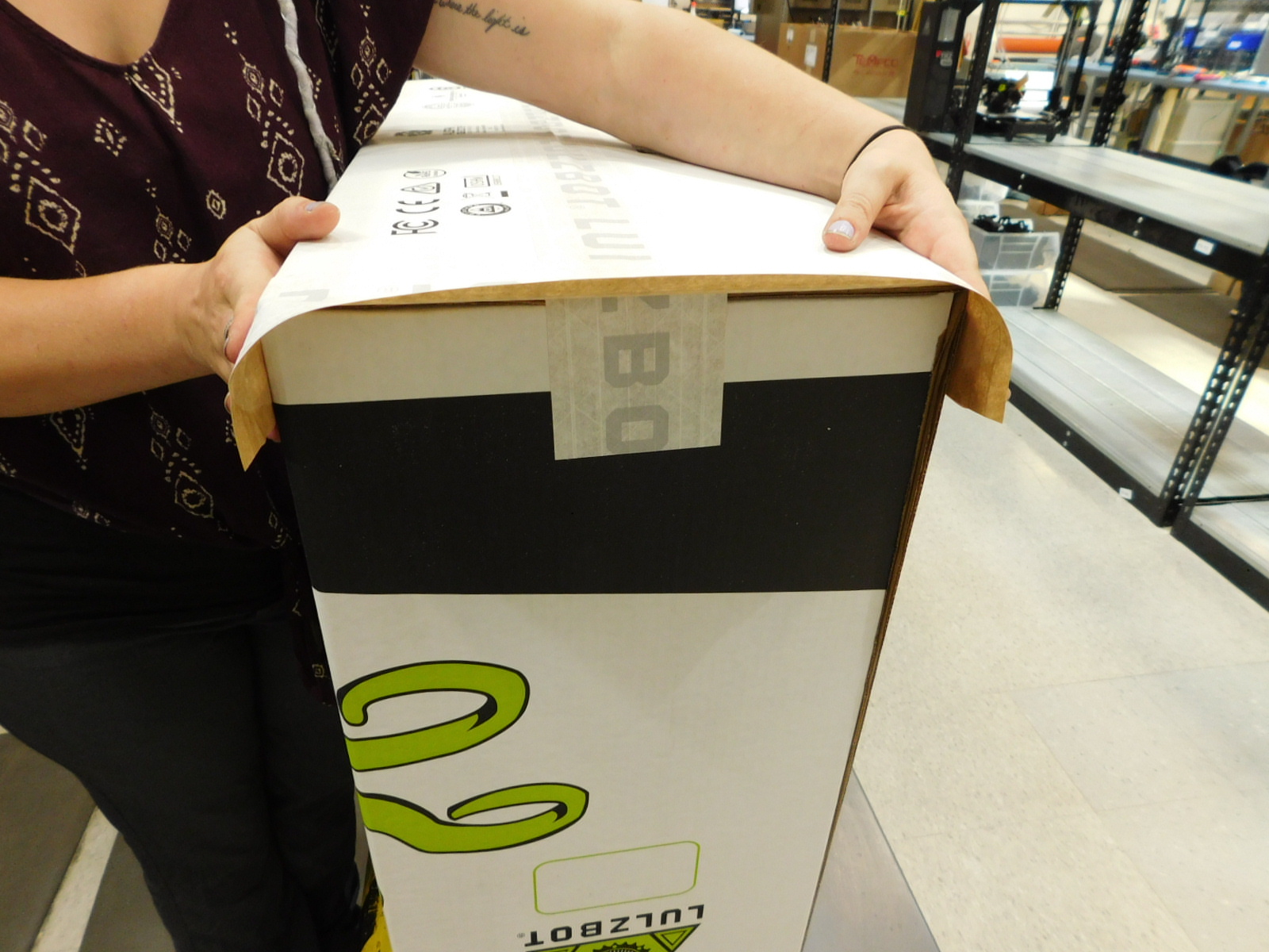
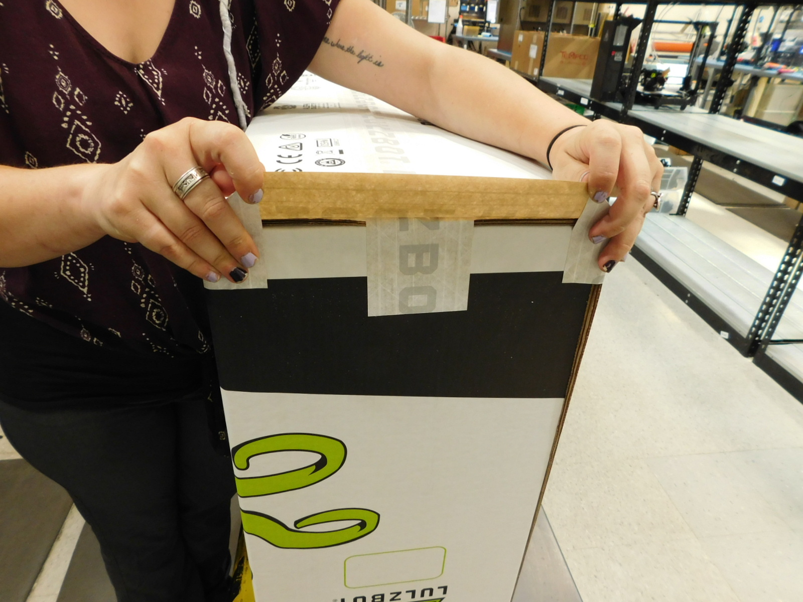
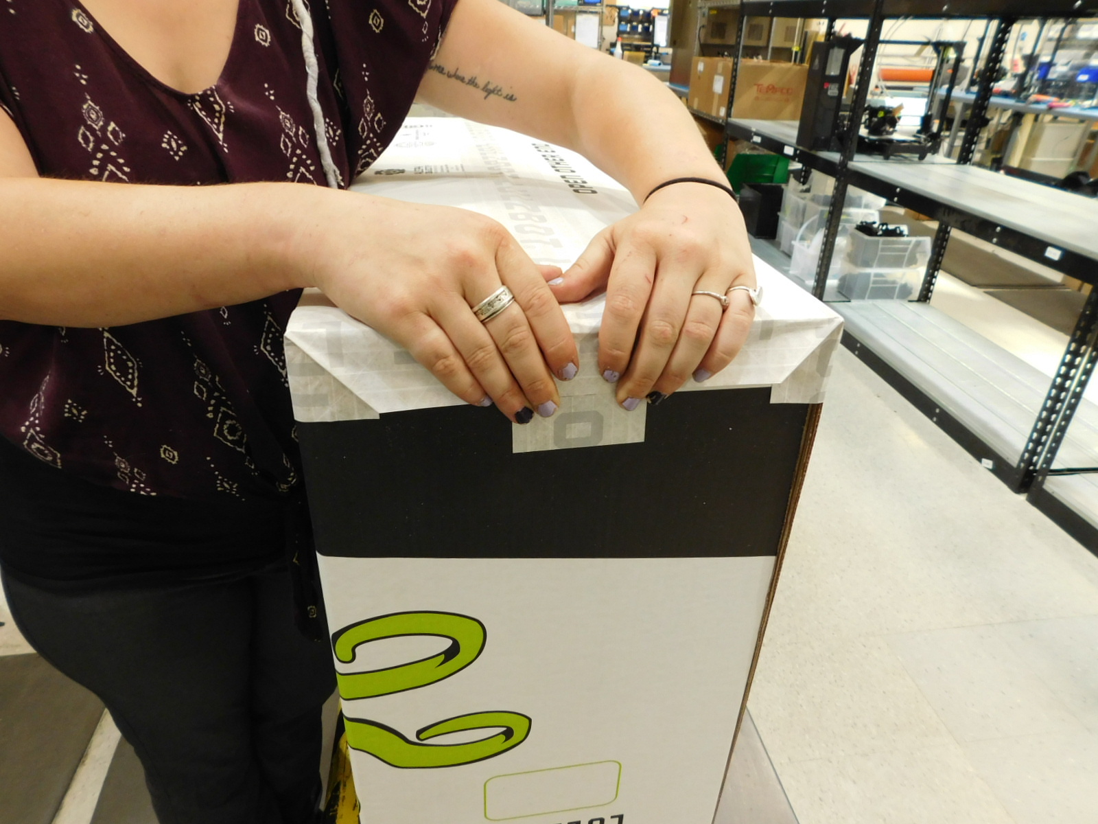
Obtain one 16 inch length of Lulzbot Reinforced Gummed Tape [SH-PG0131] from the tape dispenser and use it to cover the short box edge by placing it center over that edge, pressed flat on the top of the box. Then press the tape down over the long sides of the box, in towards the short side, and fold the lip of the tape down flat. Press firmly. Repeat this process for the other short top box edge.

Ensure the packaging of the printer is properly reflected in the spreadsheet log, see your supervisor for questions regarding logging.
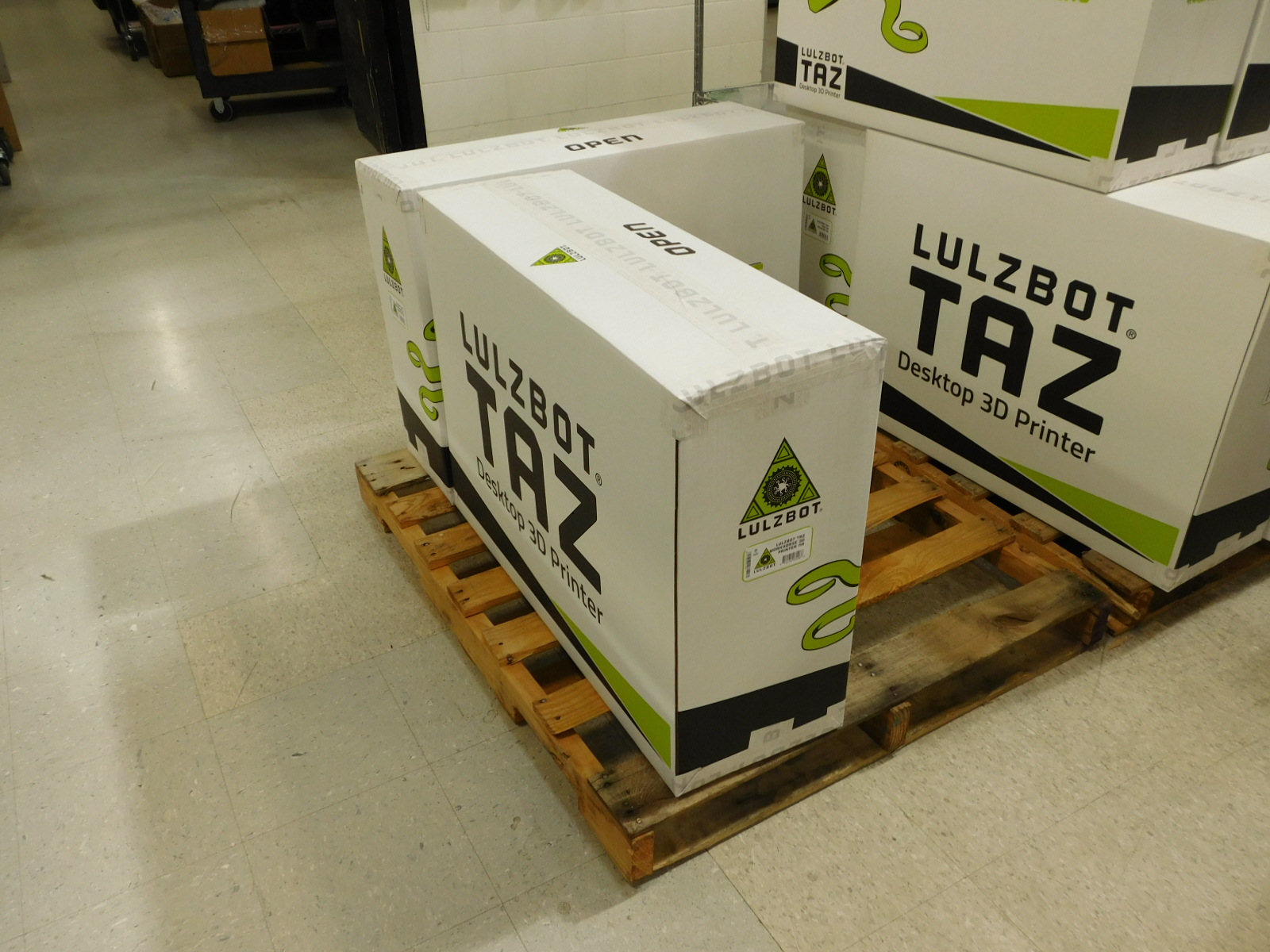
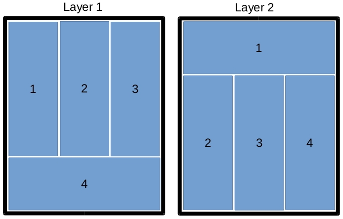
Place the boxed unit on a pallet, no more than 2 layers in height, 4 printers per layer.