Open HardwareAssembly Instructions
Guides for installation and assembly of the LulzBot line of products made by FAME 3D LLC.
Guides for installation and assembly of the LulzBot line of products made by FAME 3D LLC.
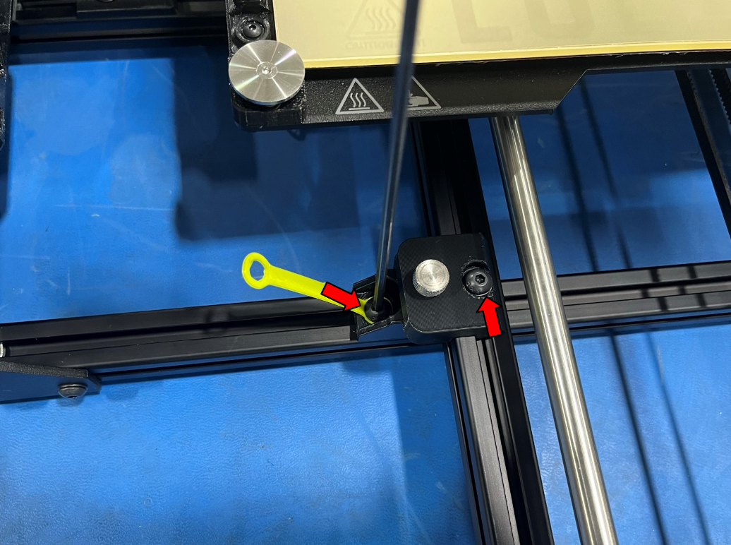
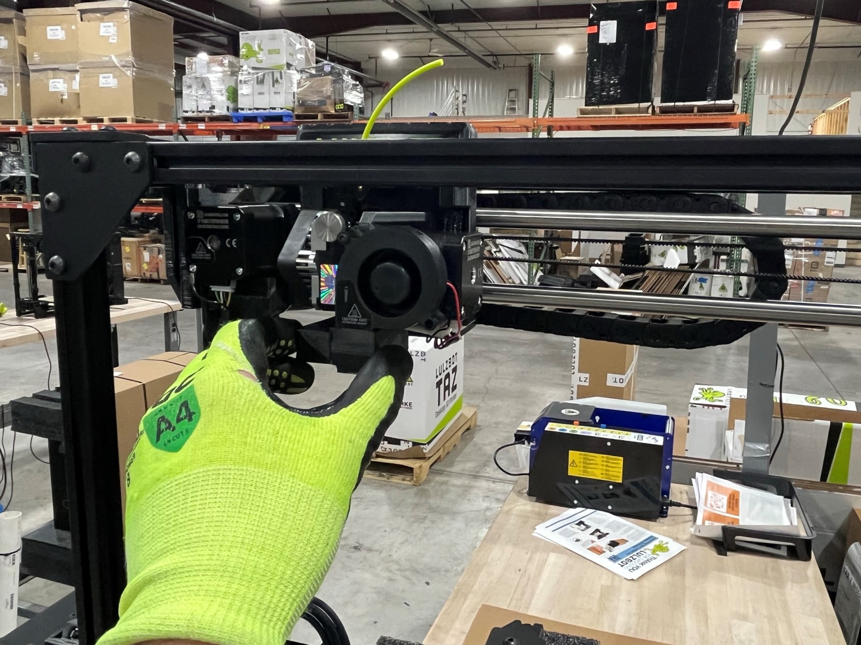
Place the calibrated TAZ Pro XT on the packaging table. Then loosen the screw that is holding the Y cable holder in place.
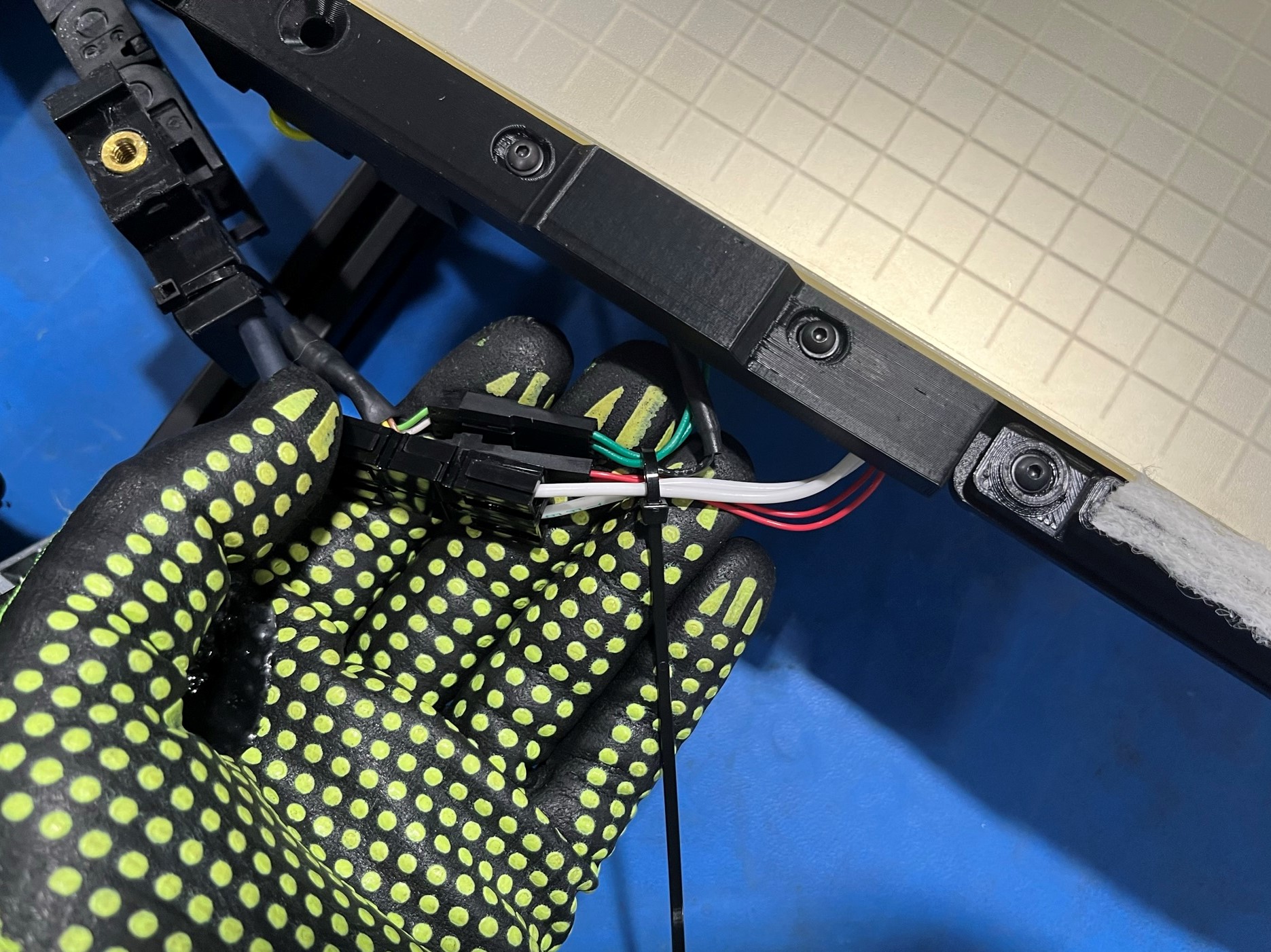
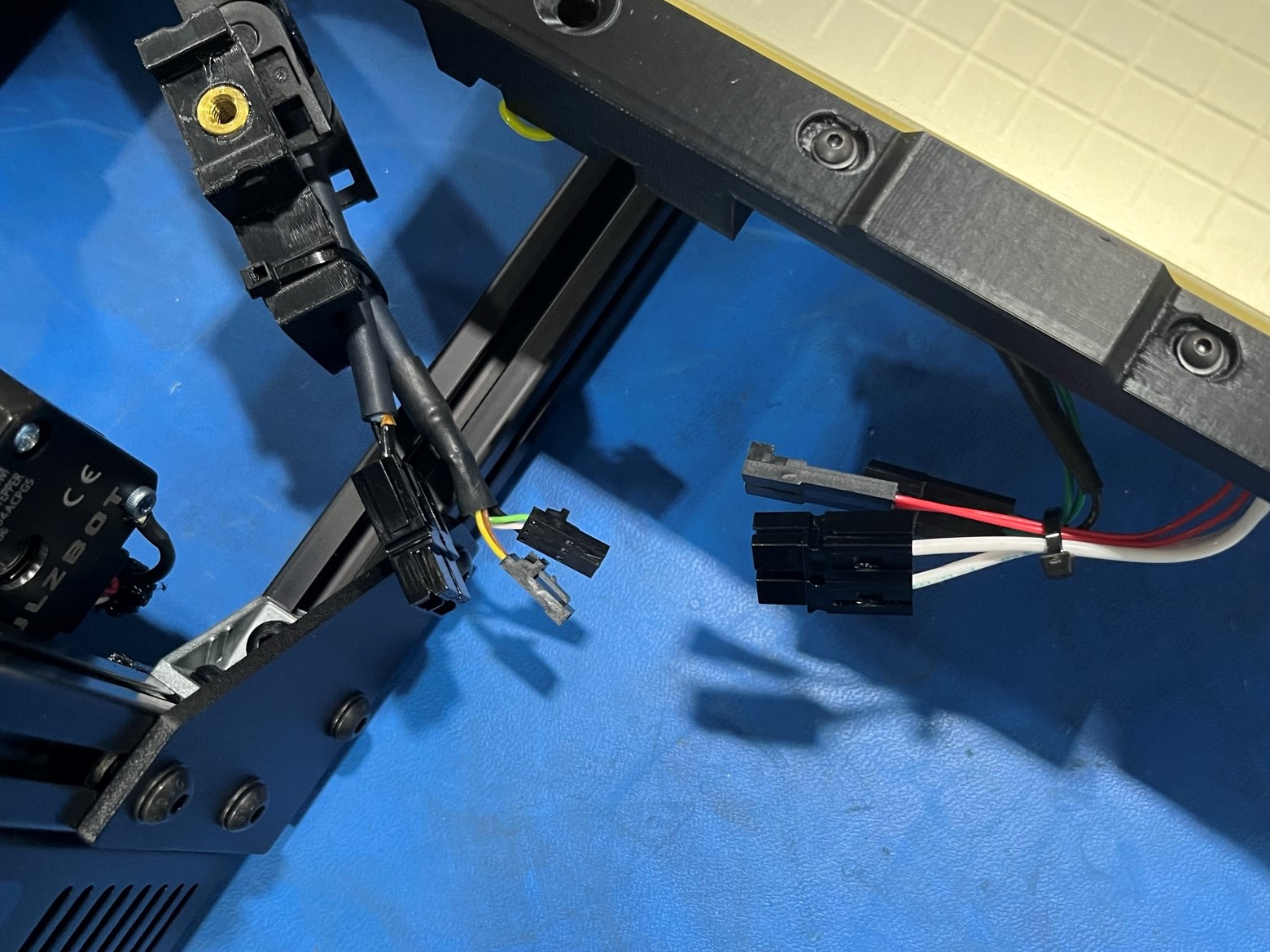
Once the Y cable holder is free from the bed use a cable tie [HD-MS0058] to loosely secure the three bed wires. Make sure to keep the cable tie loose, it is just to keep the wires together. Then disconnect the three wires.
Before removing the thumbscrews make sure the screws that are holding the bed mount chassis and table are both tight. Repeat for the other corners.
Then remove the four thumb screws to free the bed and place them in the four holes in the table so they don't get lost.
Disconnect the Y motor harness and then lift the bed off the chassis and set it next to the printer,


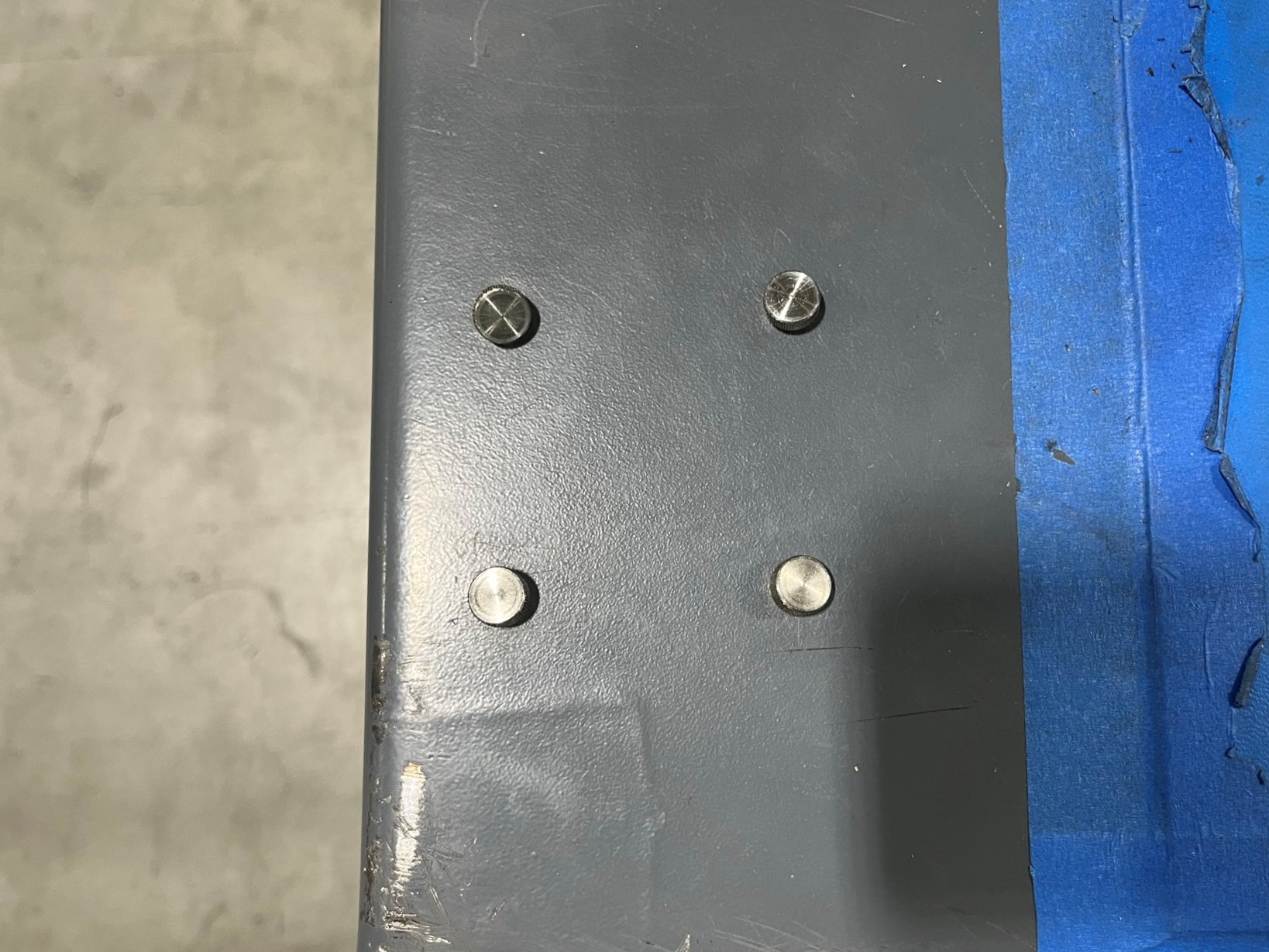
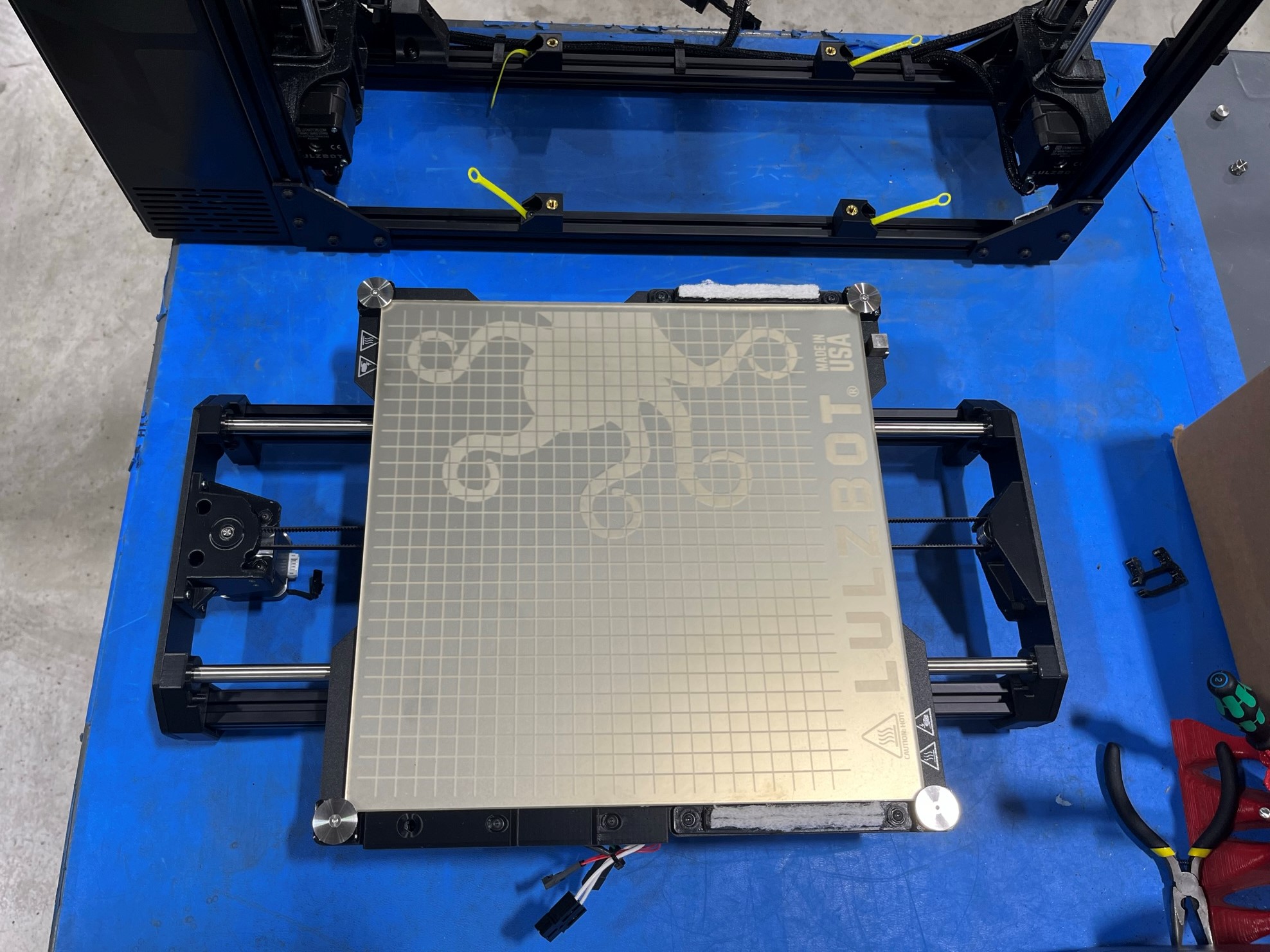
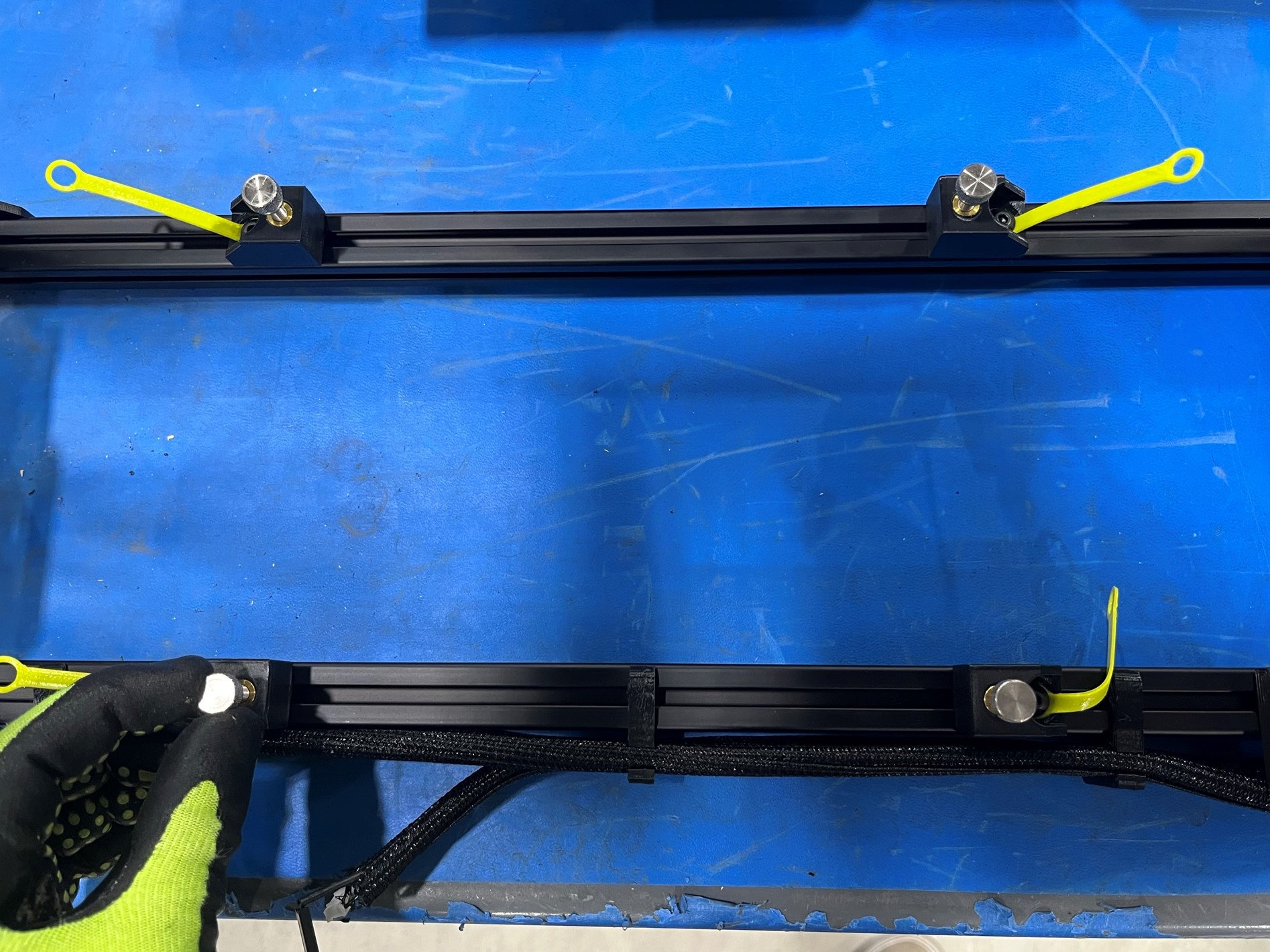
Thread the thumb screws back into the bed mount chassis parts. These don't need to be fastened all the way just enough to say in place. Make sure all four bed mounts have a thumb screw.
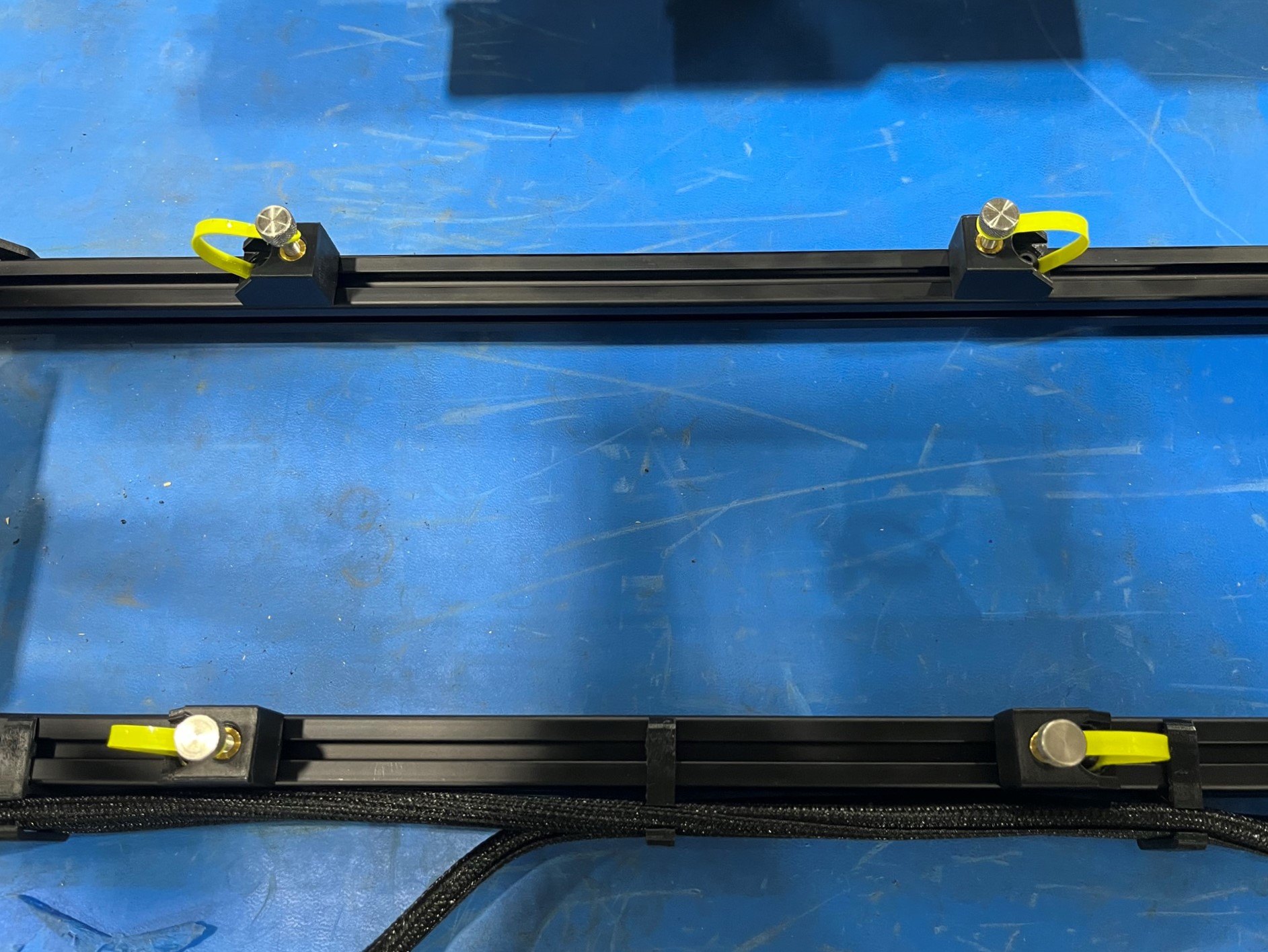
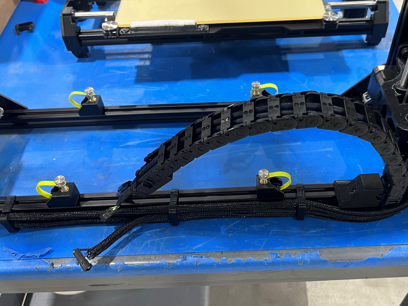
Then take the green flexy tether and place it over the thumb screws. Make sure the tether is seated inside the groove on the thumb screw.
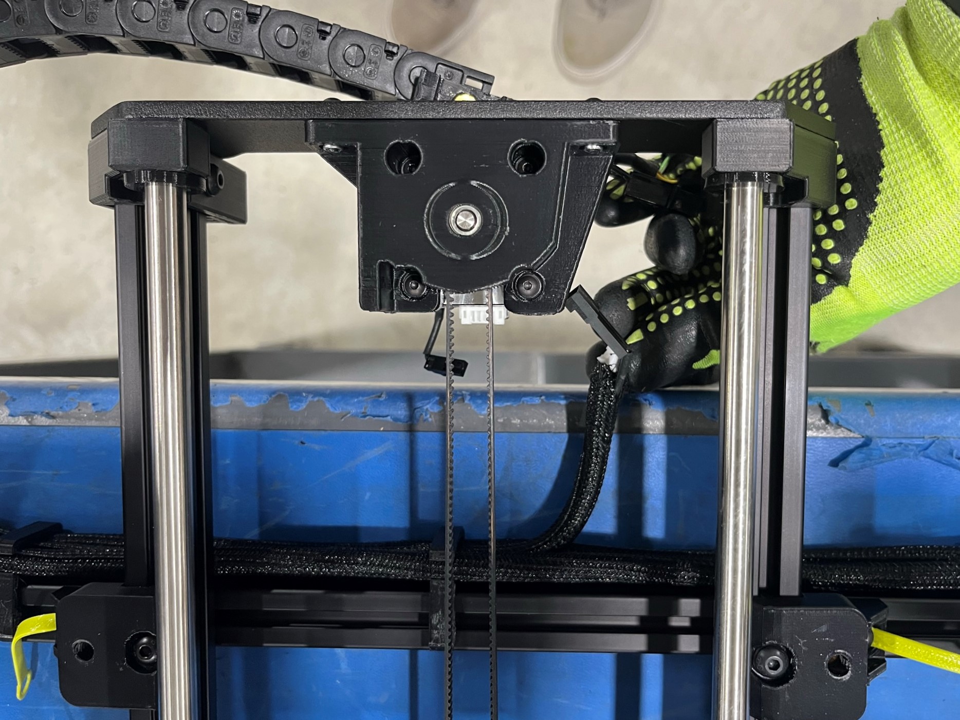
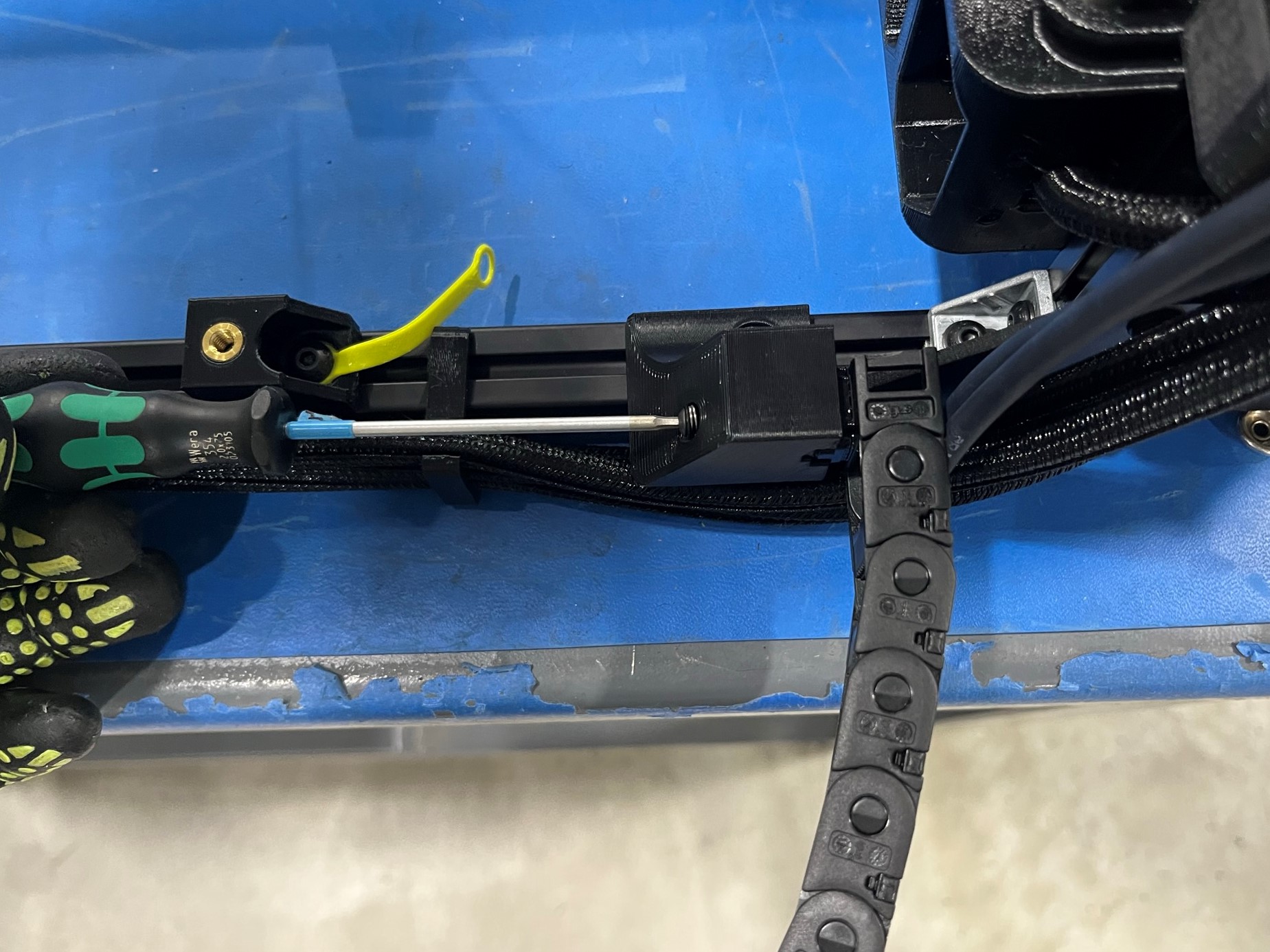
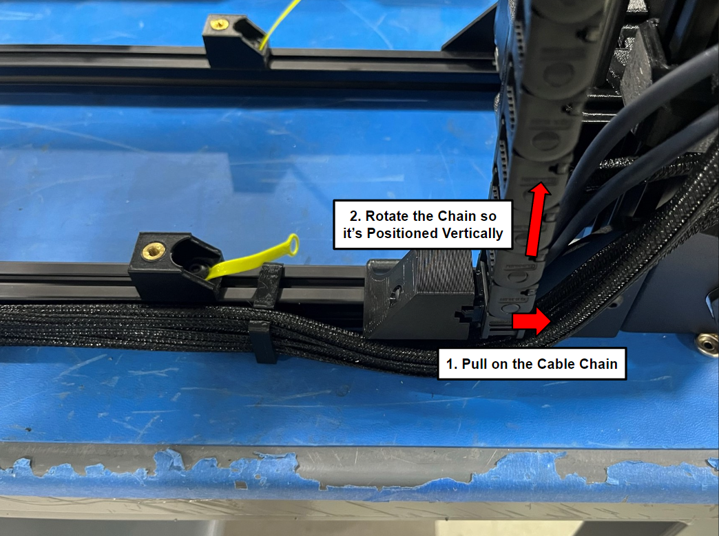
Now loosen the screw inside the Y chain pivot mount, once it loose pull on the cable chain and rotate it so that is vertical. Make sure the cable chain bends over and rests on top of the extrusion to protect the wires.
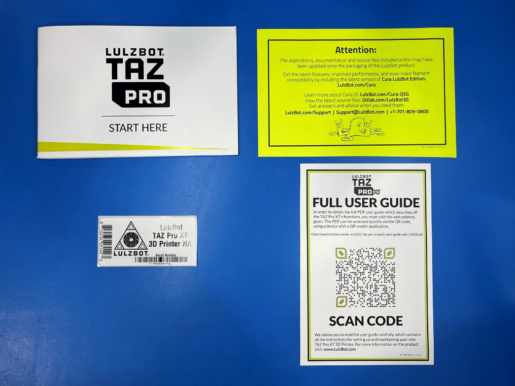
Prepare the following document:

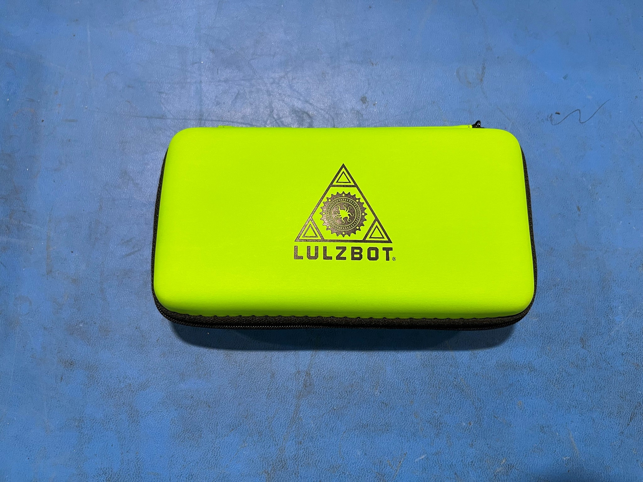
Open the TAZ Pro tool kit and find the flash-drive and replace it with the TAZ Pro XT flash-drive [EL-MS0579] then close the tool kit.

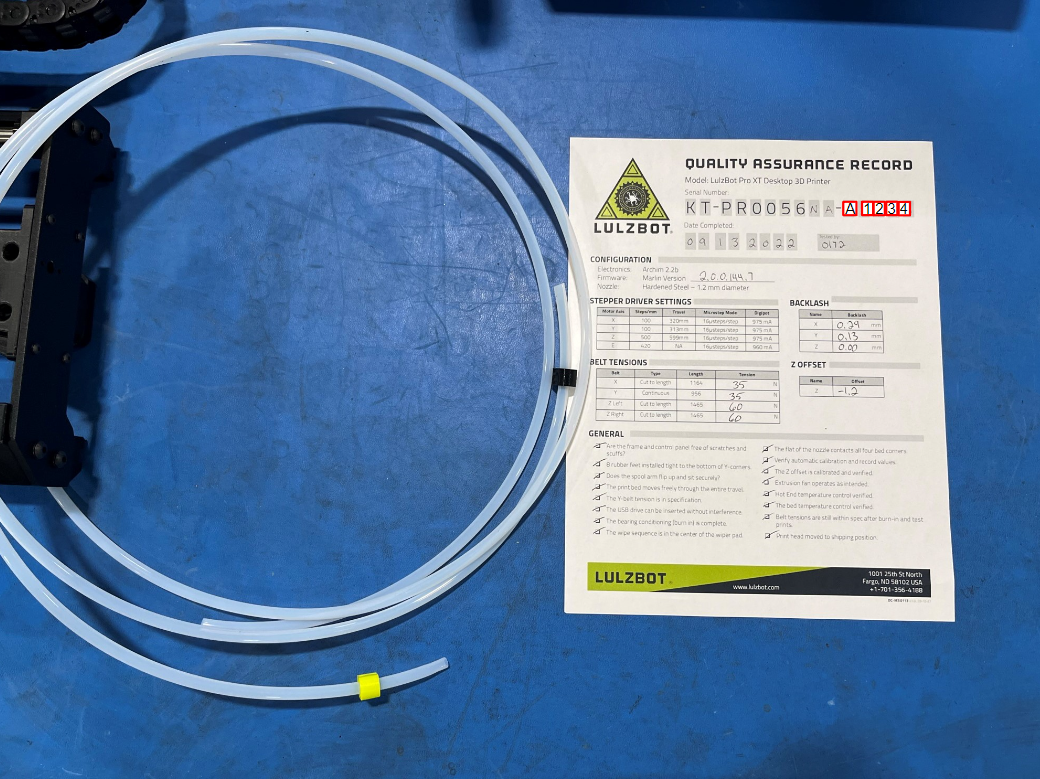
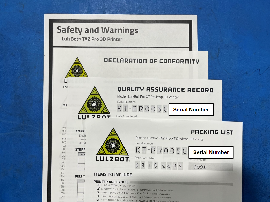
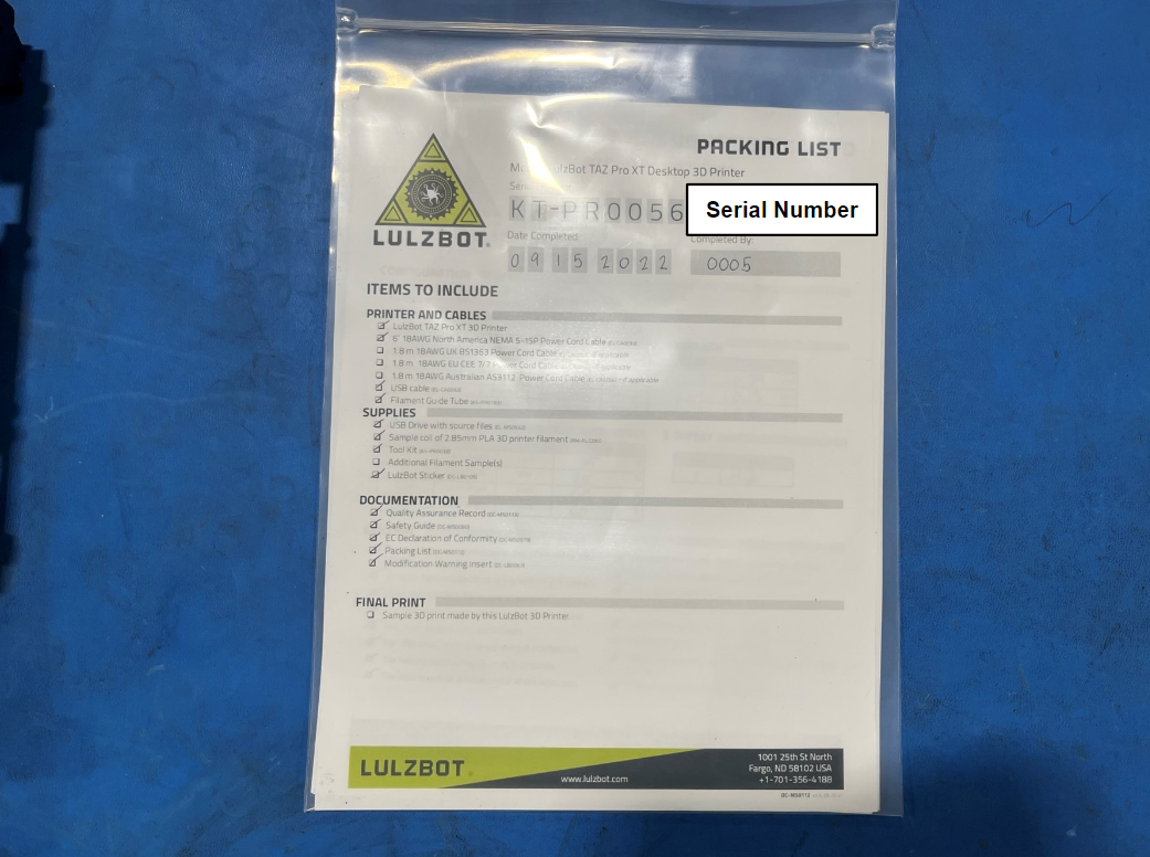
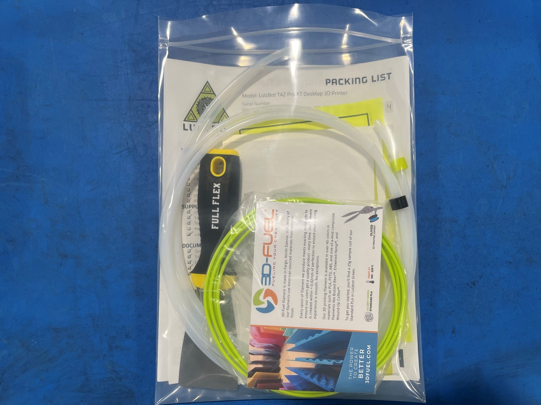
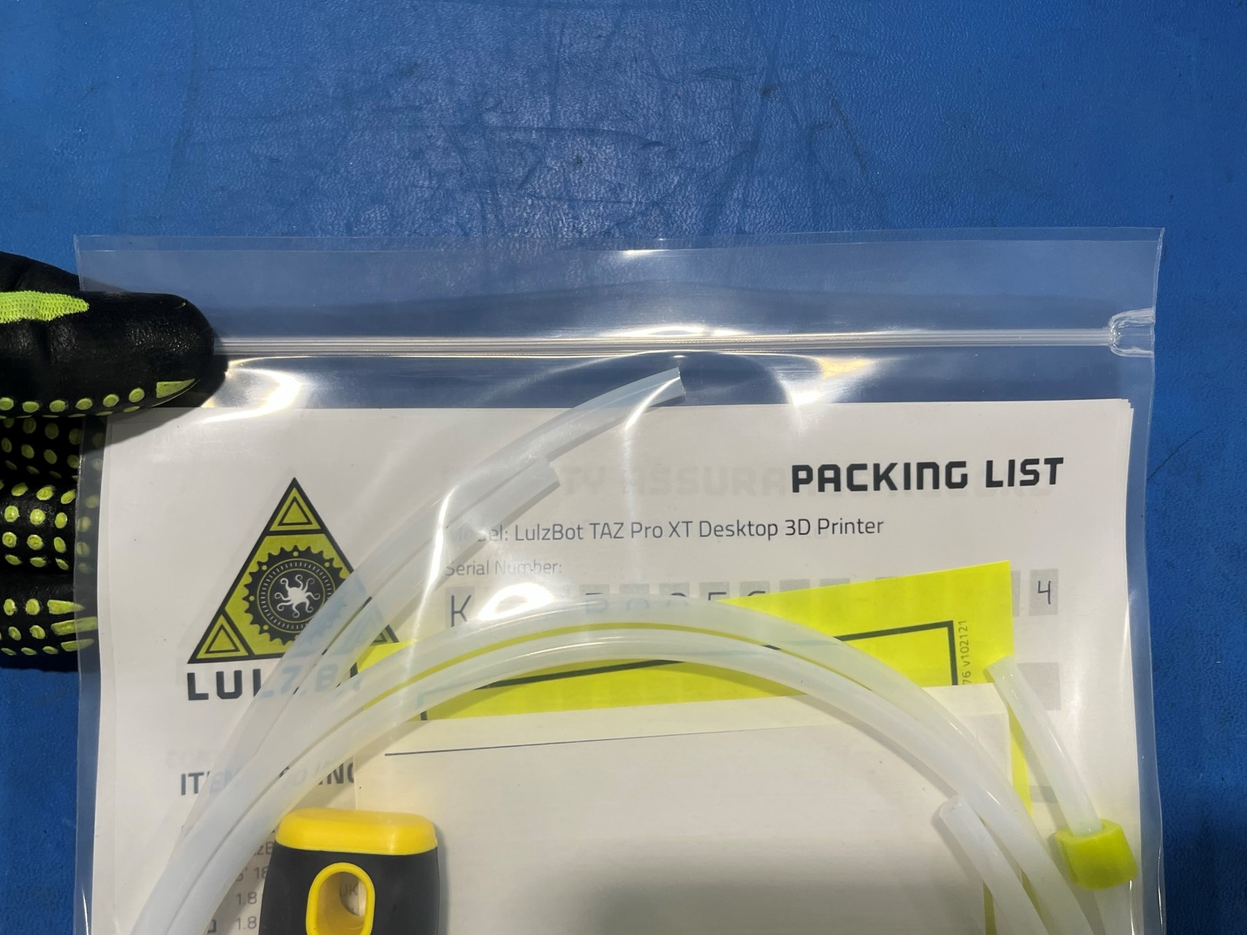
Complete the packing list [DC-MS0112] using the serial number on the printer and check off all the materials that are going to be sent with the printer.
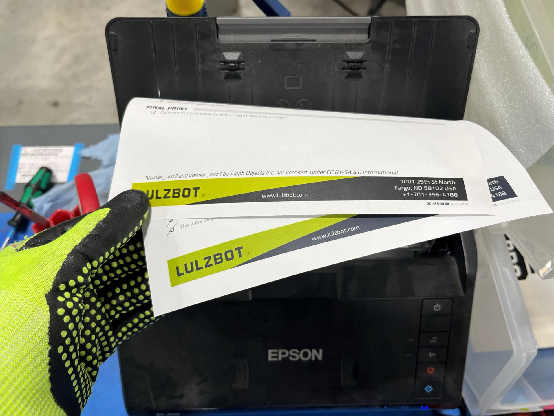
Then place the packing list over the quality assurance record and slide them into the scanner. Note: Place the papers in upside down and backwards.
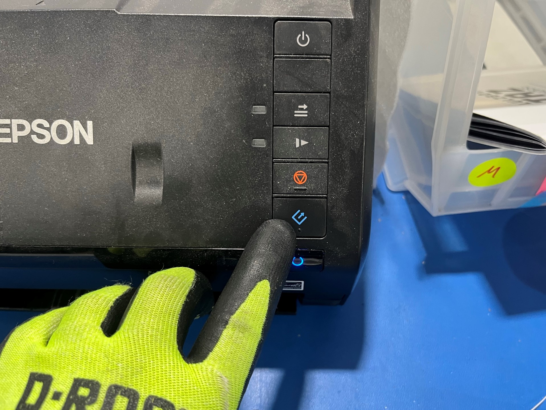
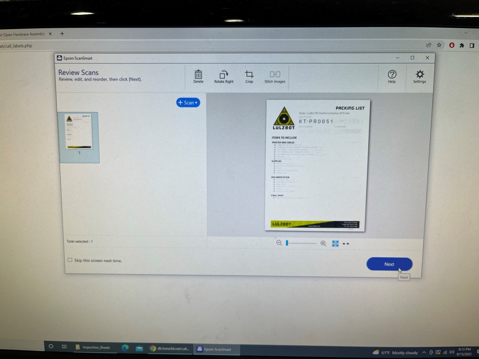
Once the papers are in the scanner hit the bottom blue button. Then look at the computer and preview the scanned copies. You are able to rotate the sheets on this screen by clicking on Rotate Right button. If the scans look good click Next.
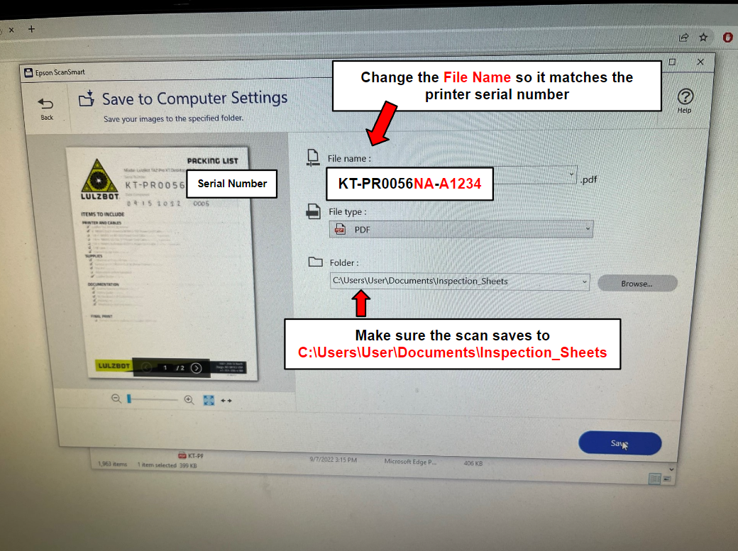
The next screen will ask you to select an action, select Save its an arrow pointing into an open folder. On the next screen change the file name to the printers serial number KT-PR0056NA-A1234 make sure the numbers match.
Verify that the folder is Inspection_Sheets then hit save.


Start with the Safety and Warnings, then set the Declaration of Conformity on top, followed by the Quality Assurance Record and then lastly by the Packing List.
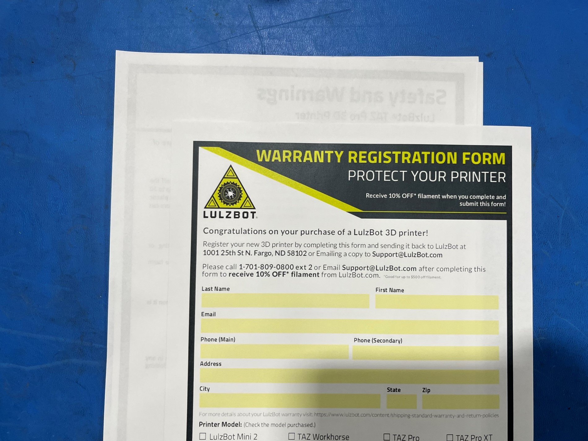
Then flip the stack over and place the Warranty Registration Form on the backside of the stack.
Now open the shipping bag 9x12" [SH-PG0083] and slide the stack of document inside, try not to wrinkle the papers while sliding them in.
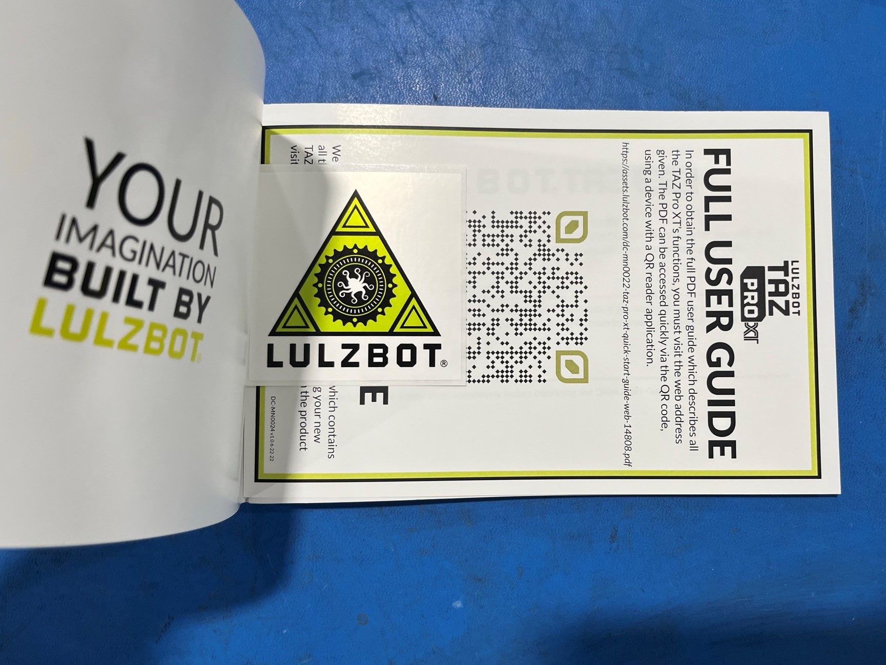
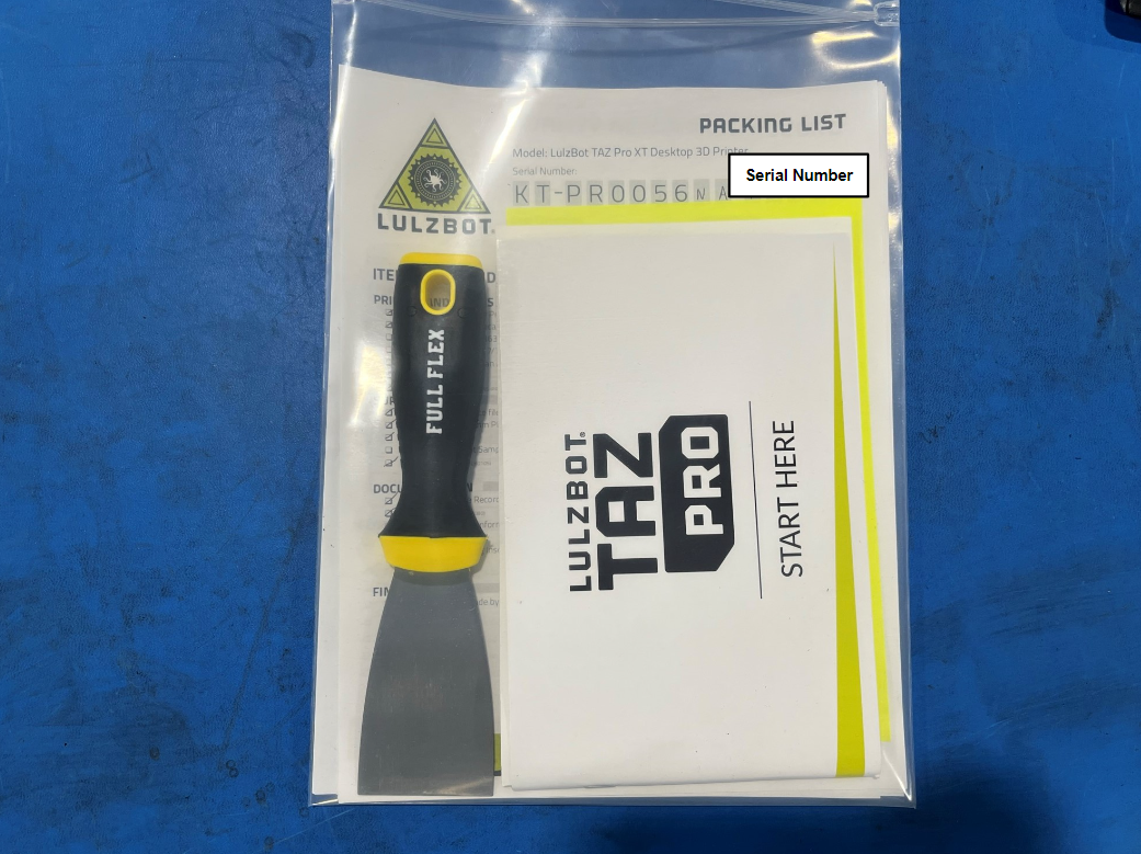
Then find the TAZ Pro quick start guide kit [AS-PK0039] and open it up and make sure the LulzBot sticker is inside. Then slide the QR code [DC-MN0024] behind the sticker and close the book.
Place the Cura update insert card [DC-MS0076] behind the quick start book, then slide them both inside the documentation bag.


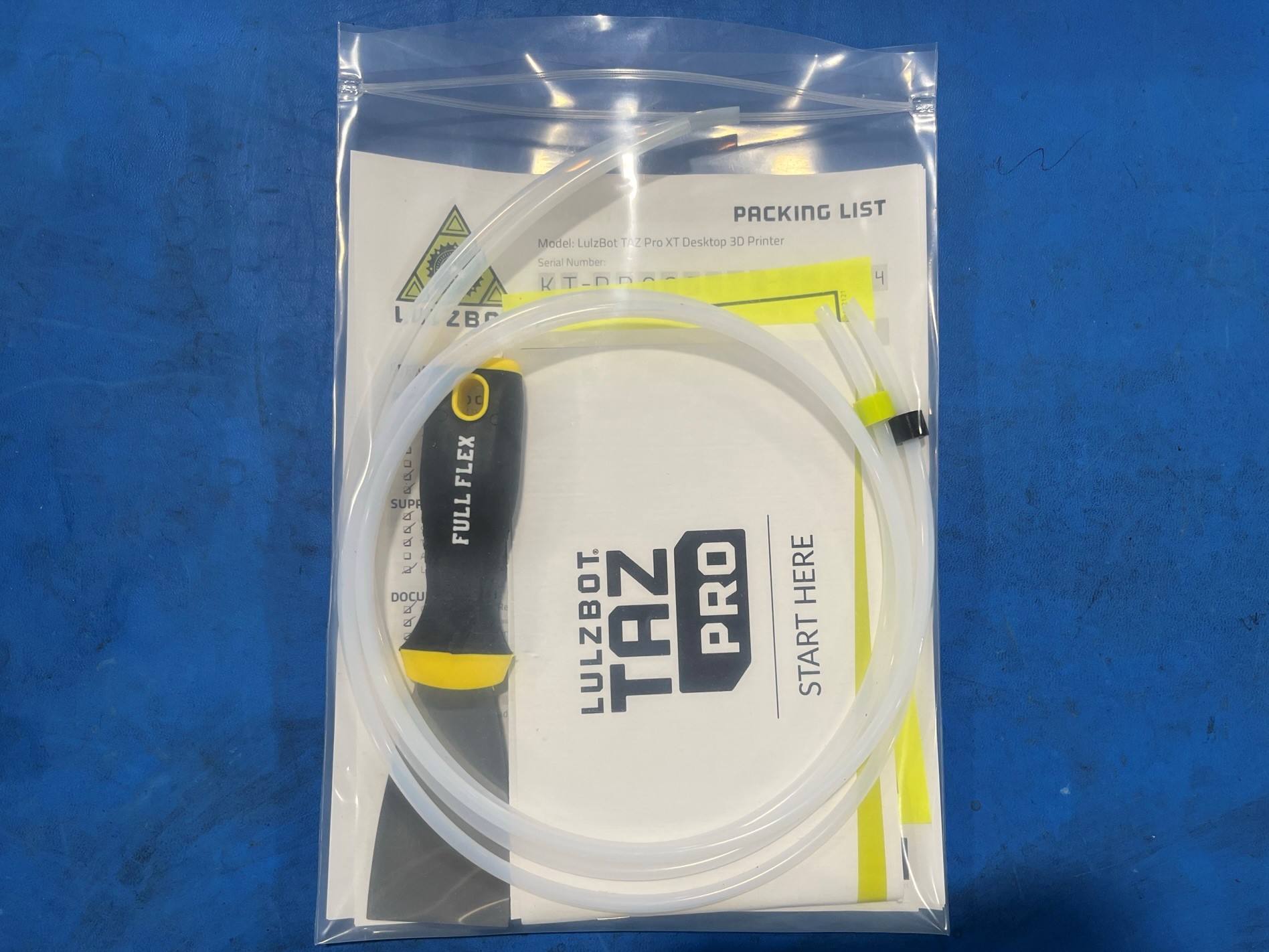
Place a print bed scraper [TL-HD0588] inside the documentation bag next to the quick start book.
Then place the 2x Pro XT feed tubes [AS-PR0183] and wrap them up and place them in the bag.
Now take a 3D-Fuel sample filament [RM-PL0305] and place it in the bag make sure the 3D-Fuel logo is facing out.
Once everything is inside the bag close it and set it a side.
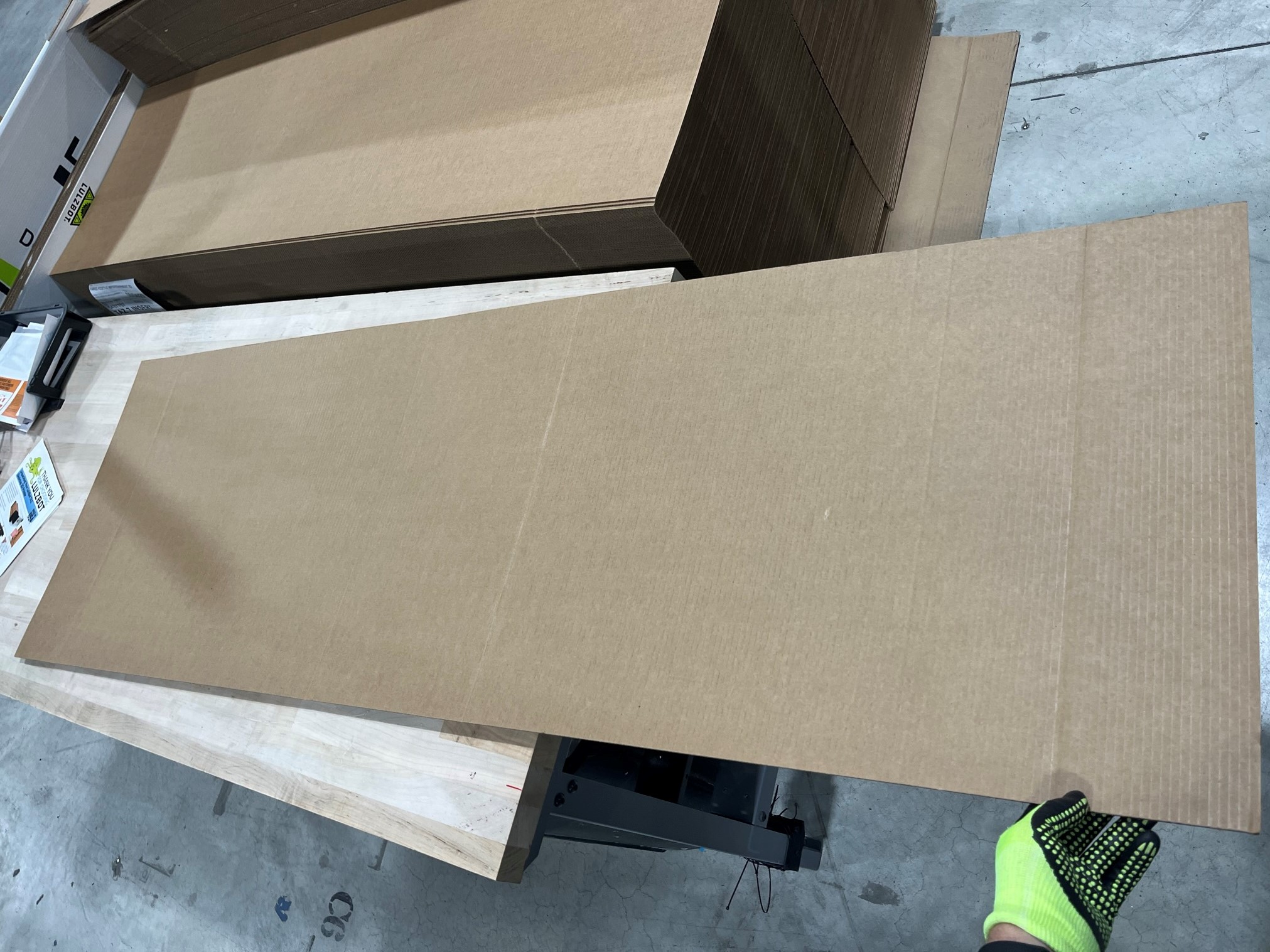
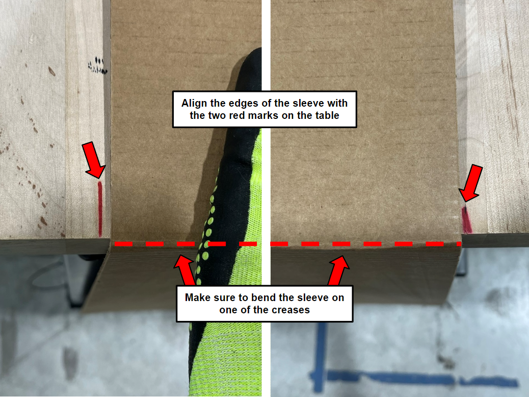
Place the TAZ Pro/WE, corrugated sleeve [SH-PA0063] on the packing table and bend one side down make sure its along one of the creases.
Note: There should be one creases left on the table.
Then align the sides of the sleeve with the two red marks on the table, then place the bottom endcap foam [SH-PA0061] on top of the sleeve. Make sure to have the control box side on the left.
Then align the right side of the foam with the edge of the table.
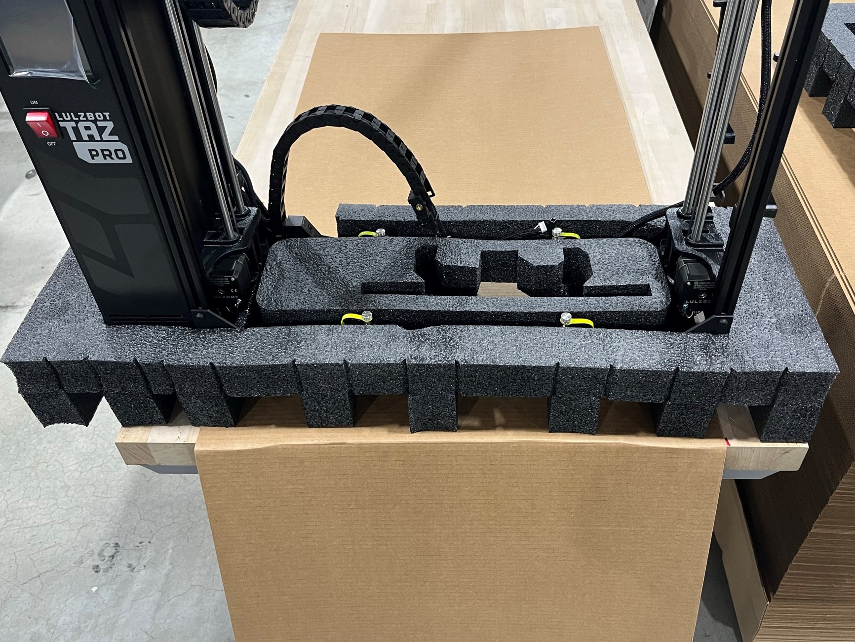
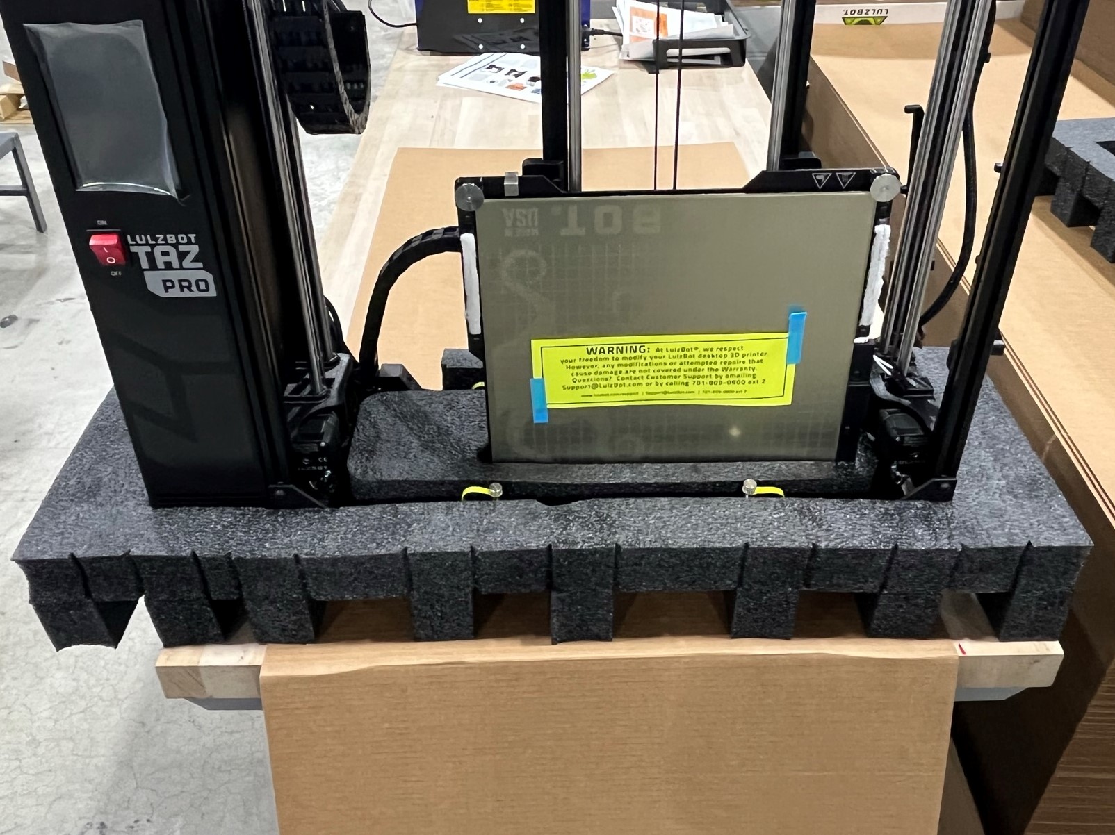
Place the printer chassis inside the foam making sure the control box aligns with the square cutout in the foam on the left side. Make sure none of the wires are under the printer chassis.
Then align the motor side of the bed with the foam and press it into the foam. It is easiest when the build plate is against the idler end so you can see the motor and foam.
Once the motor end plate is secure then slide the build plate down and push it into the foam. You may have to move the foam around to press the build plate into it.
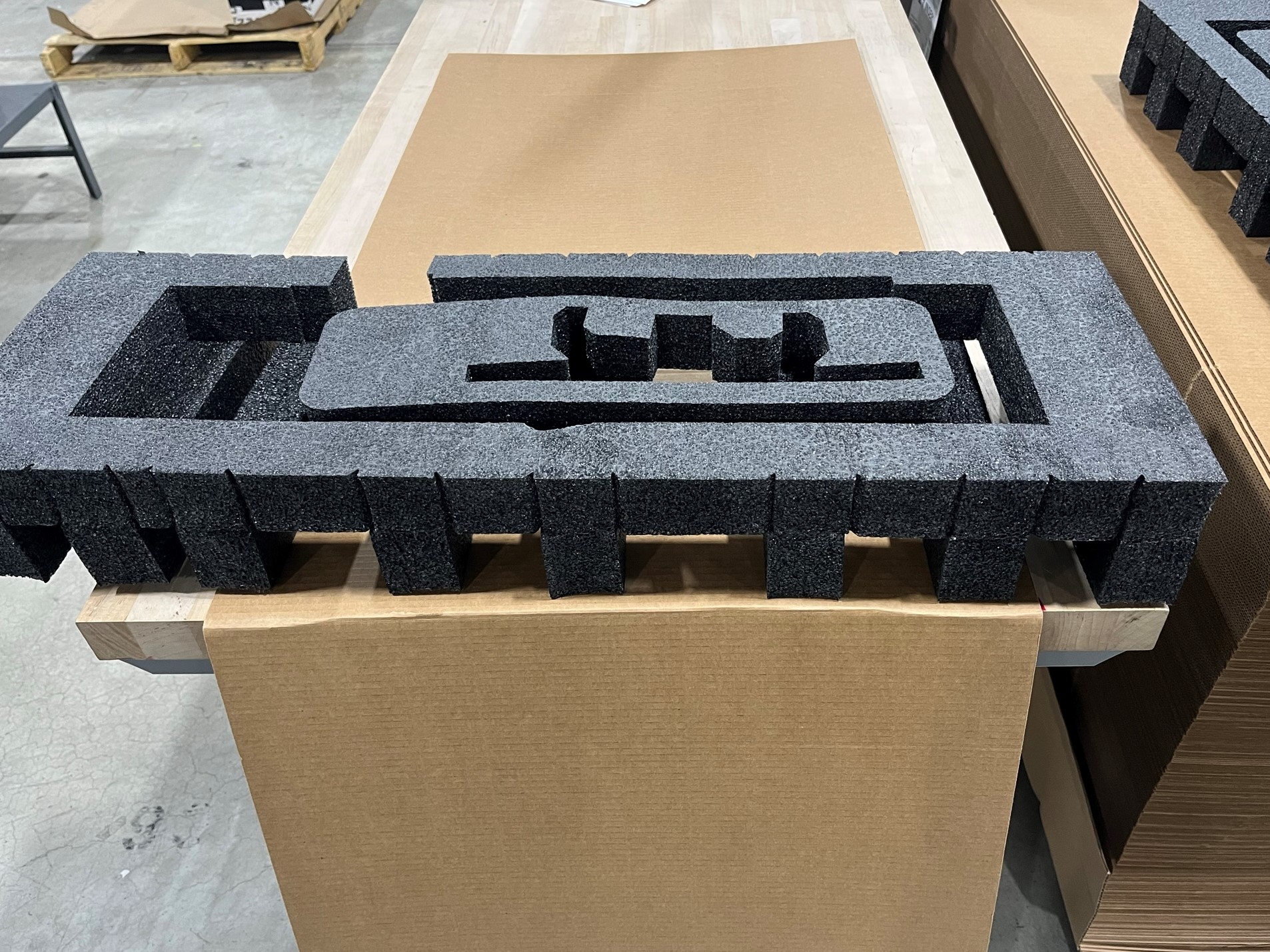
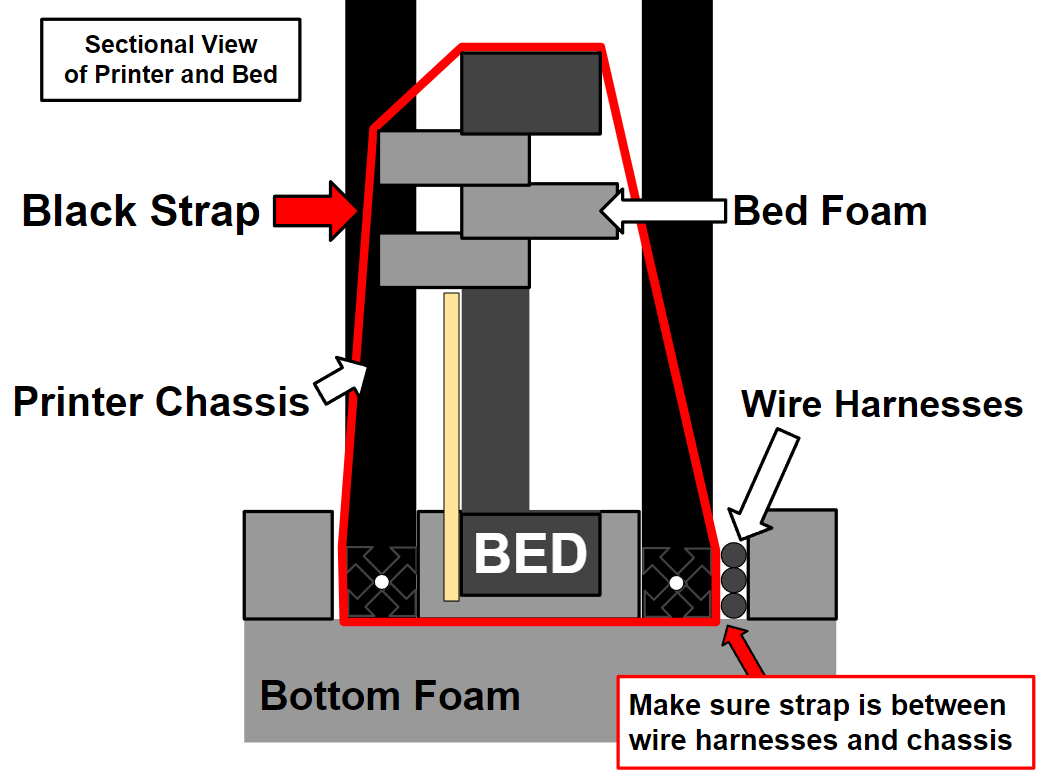
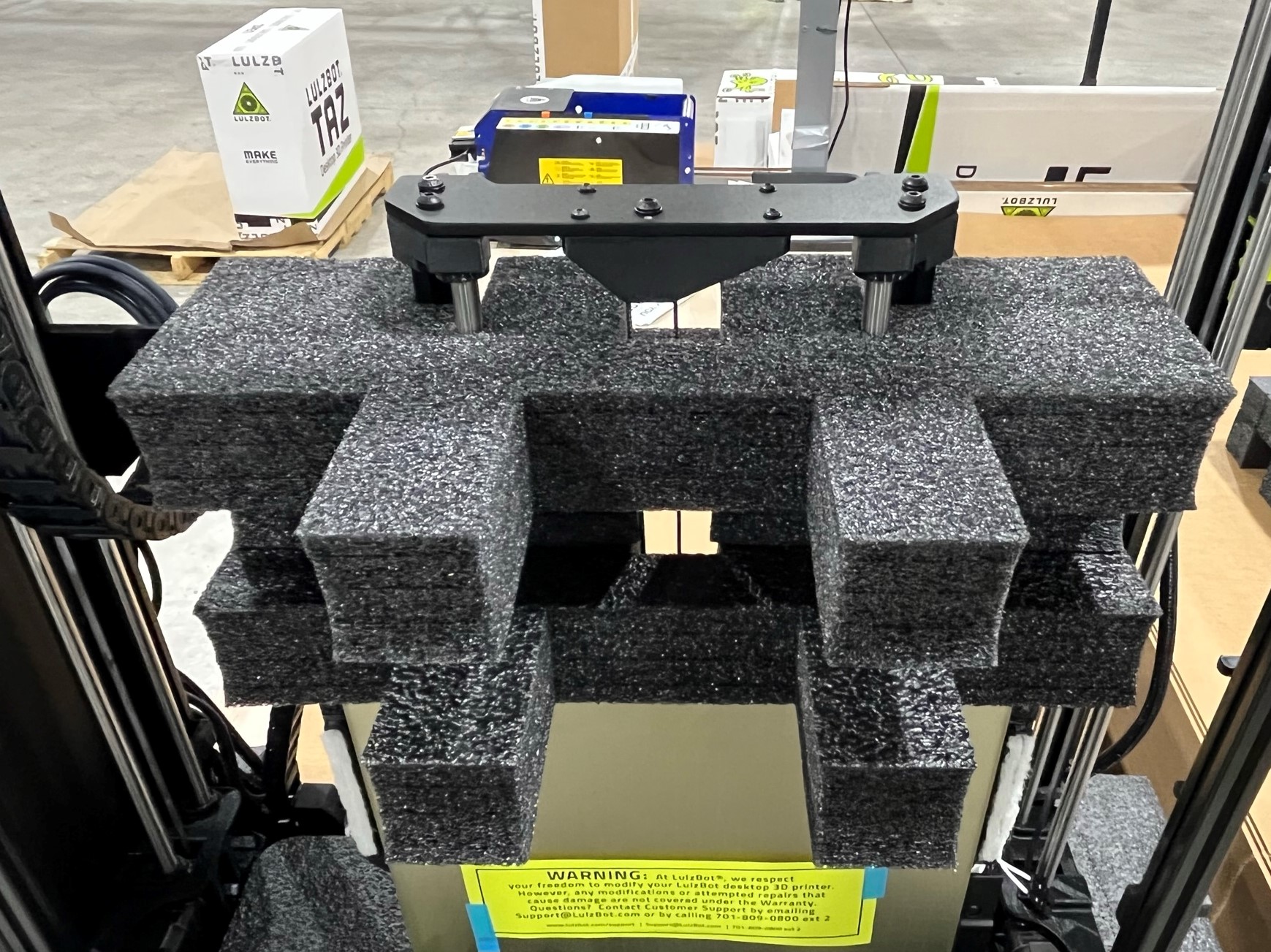
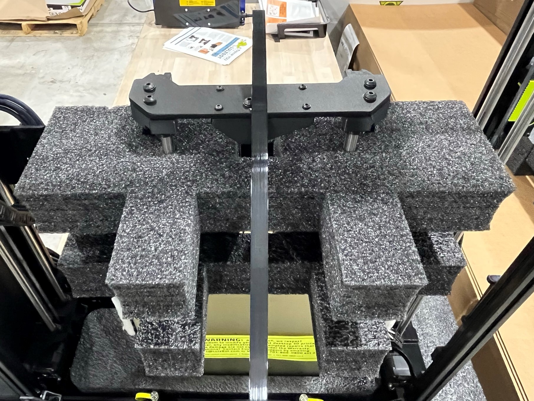
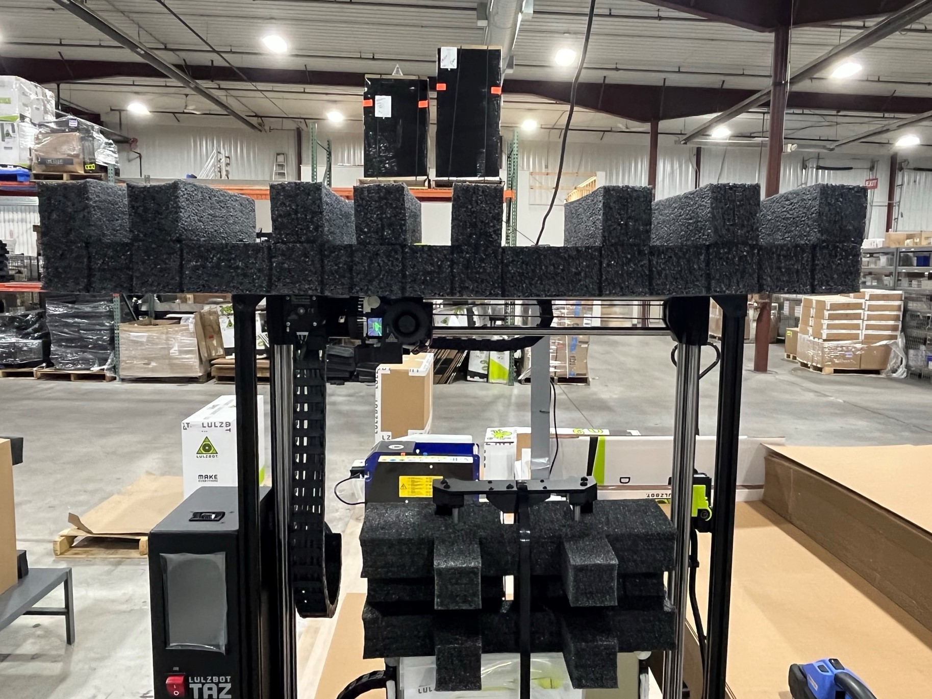
Follow the cross-sectional view of the printer and bed to secure the bed to the printer chassis.
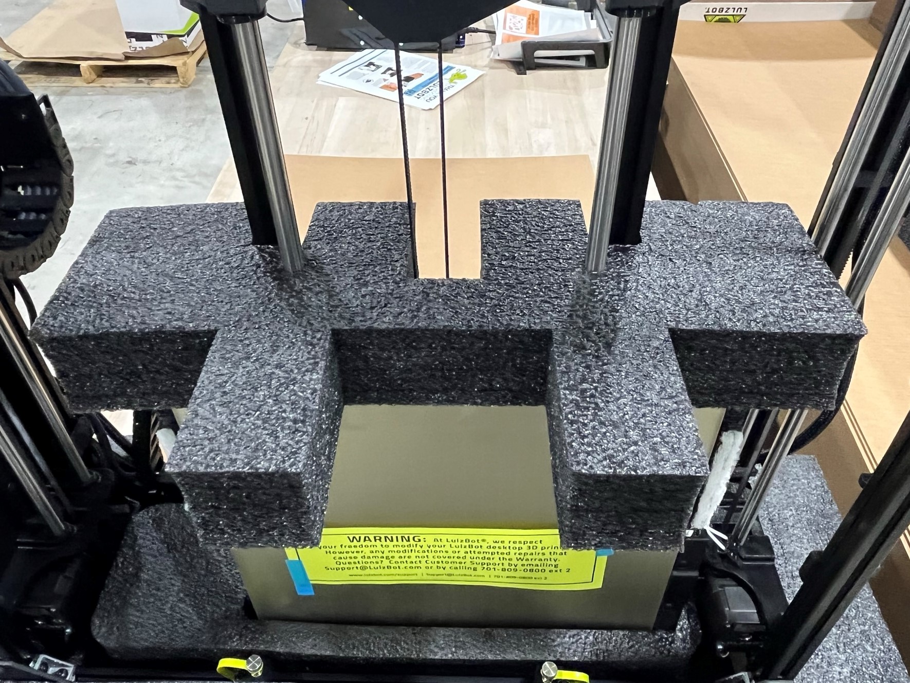
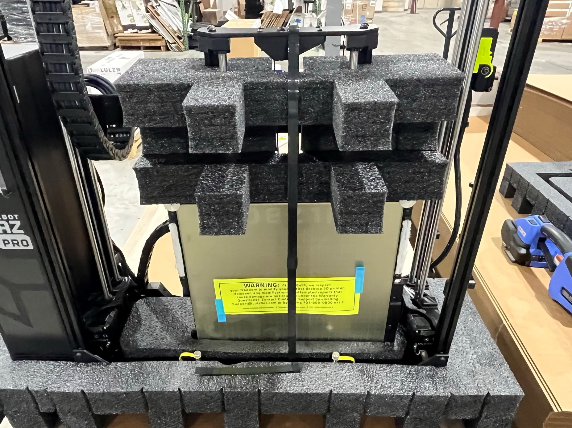
Start by placing the print head stabilizer foam [SH-PA0068] around the frame of the bed securing the build plate inside the bottom foam.
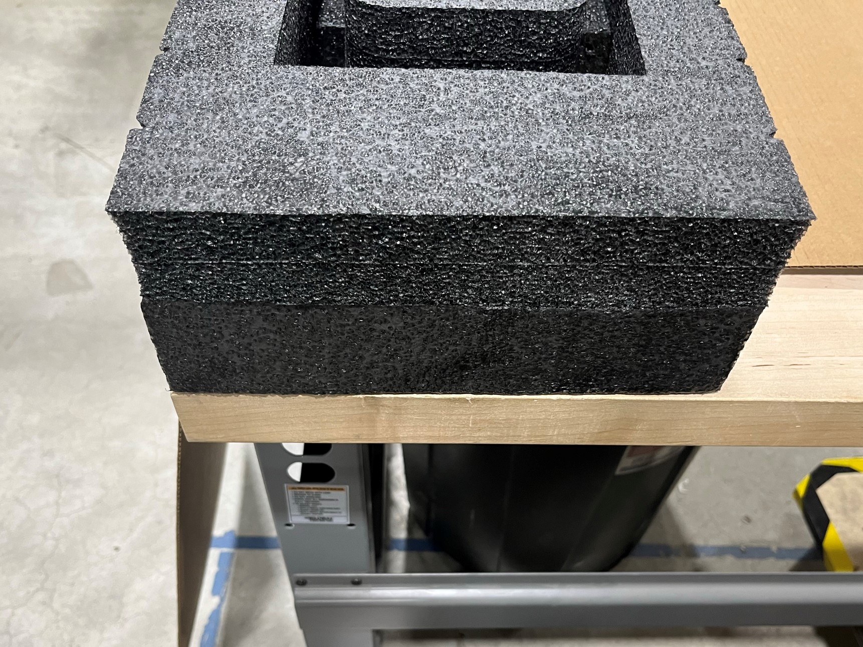
Then place another print head stabilizer foam piece above the first piece, this one should be pointing the other direction (helps keep the bed stabilized in the box).
Now place another print head stabilizer foam piece above the second piece, make sure its facing the same direction as the first piece.
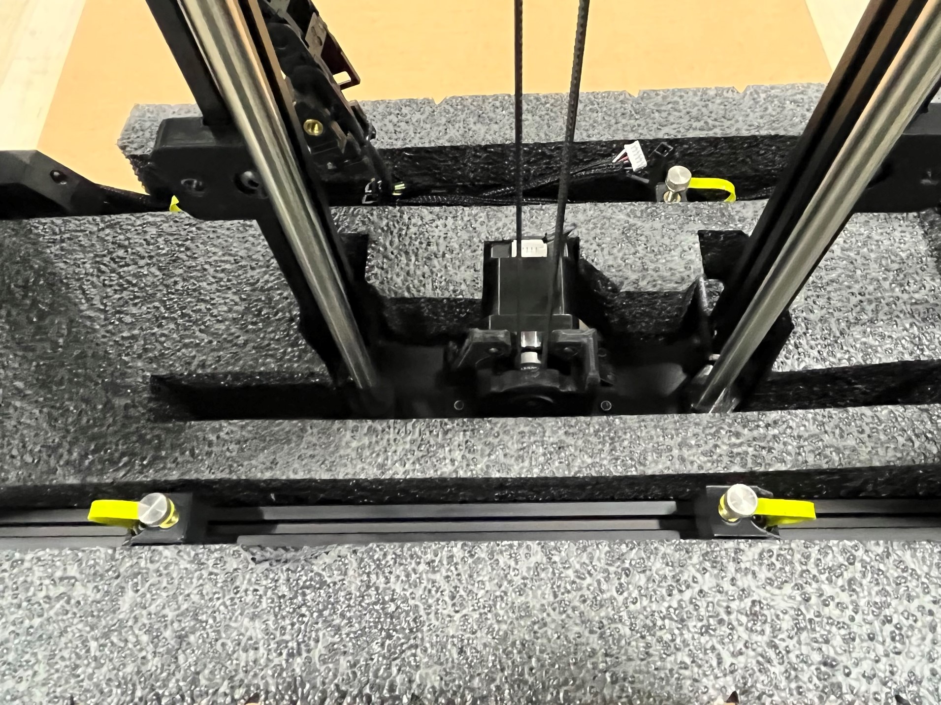
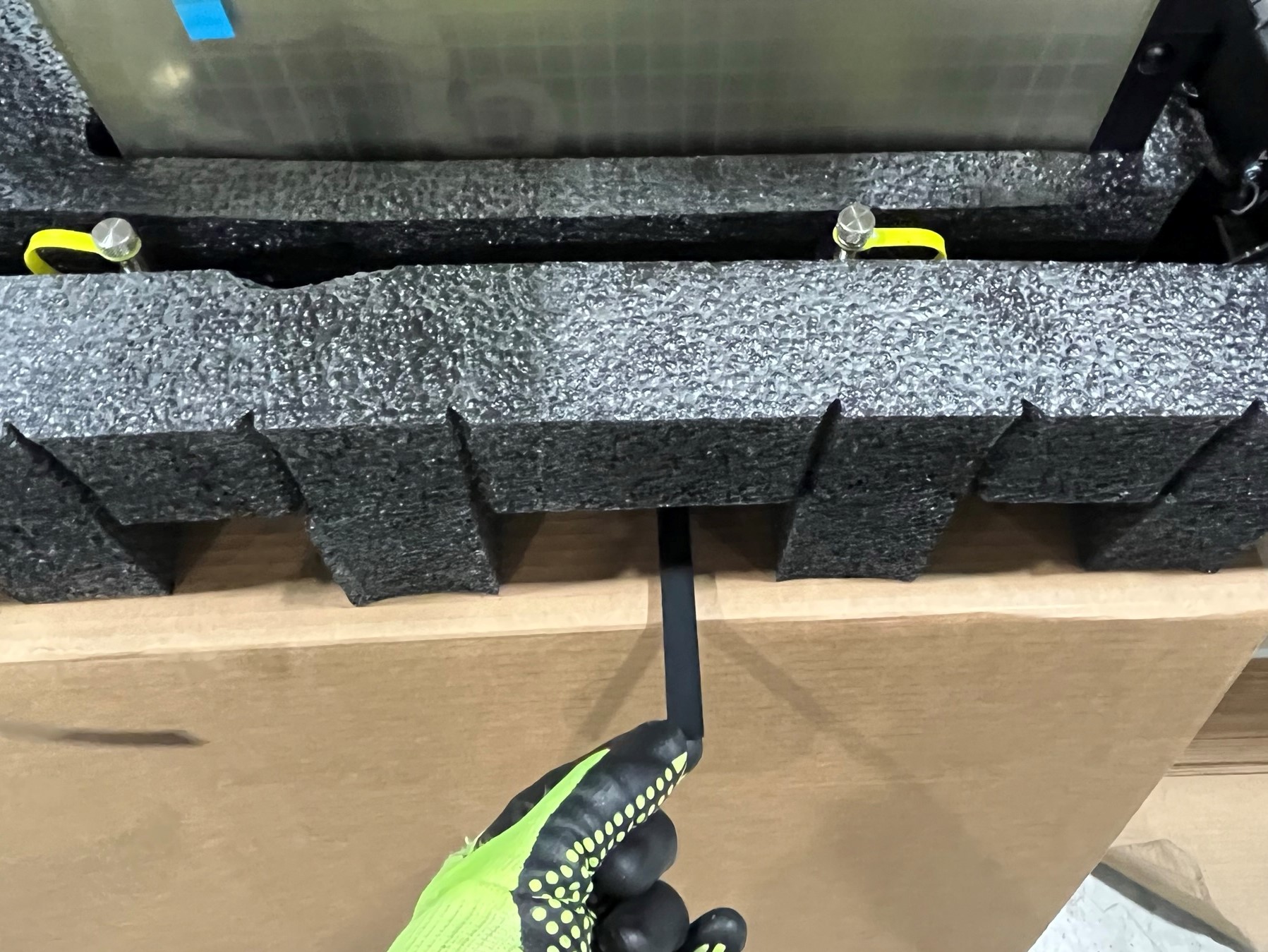
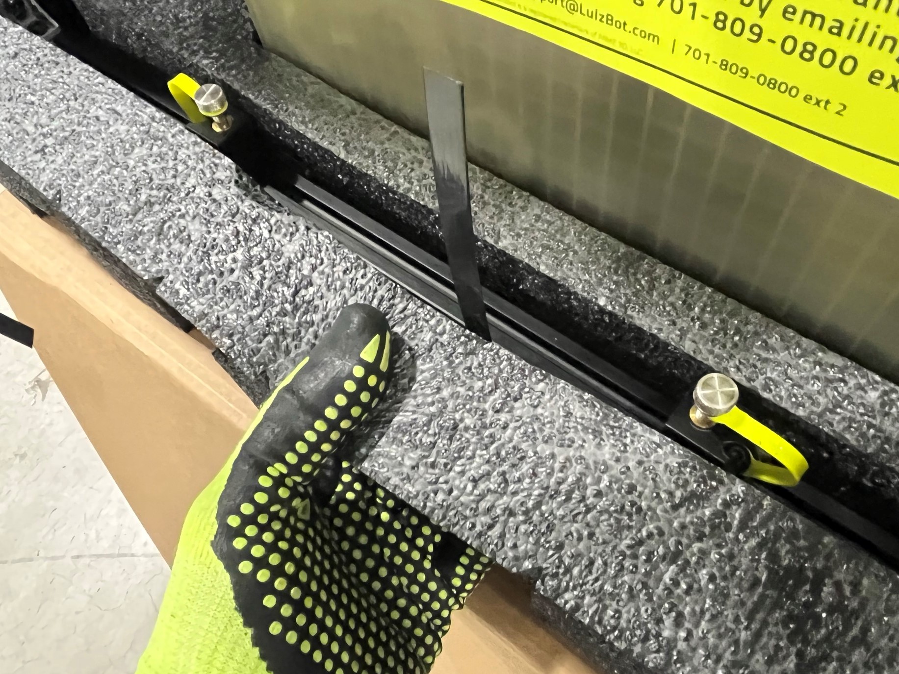
Take a section of the black poly strapping [SH-PG0080] and wrap it around the bed and the printer chassis. Make sure to go between the extrusions and wire harnesses on the backside of the printer.
The strapping should be long enough to go around the bed and chassis with a section that is overlapped, make sure the overlapped section is above the build plate.
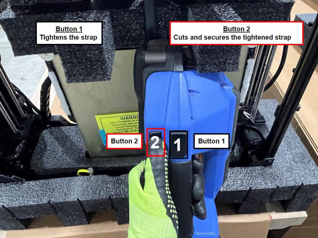
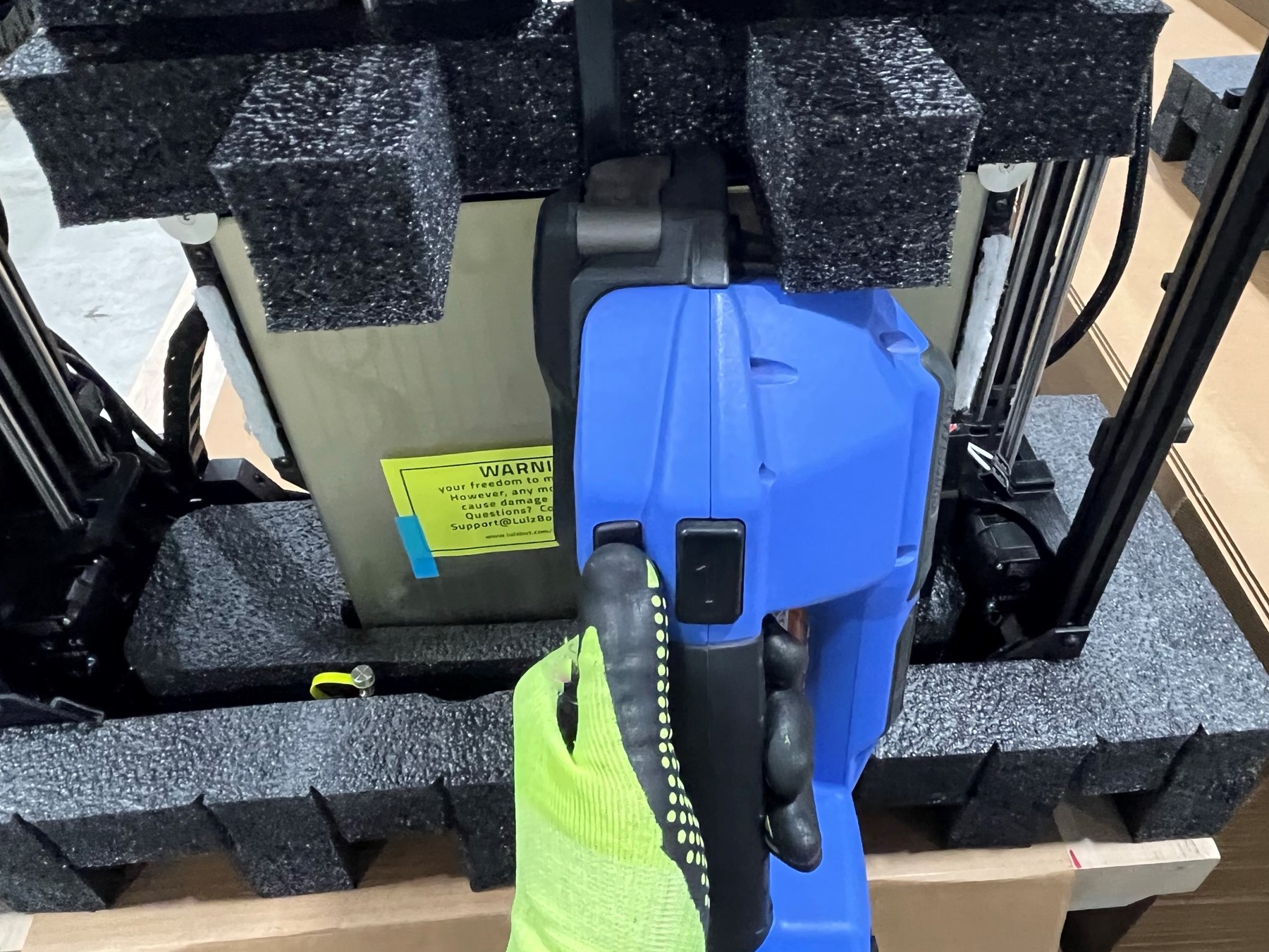
Then align the strap with the middle of the bed and use the Orgapack automatic strapping tool. Don't over tighten this scrapping, it just needs to keep the bed in place.
To use the tool follow these steps:
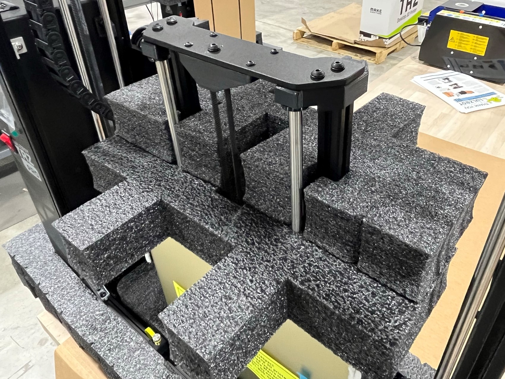

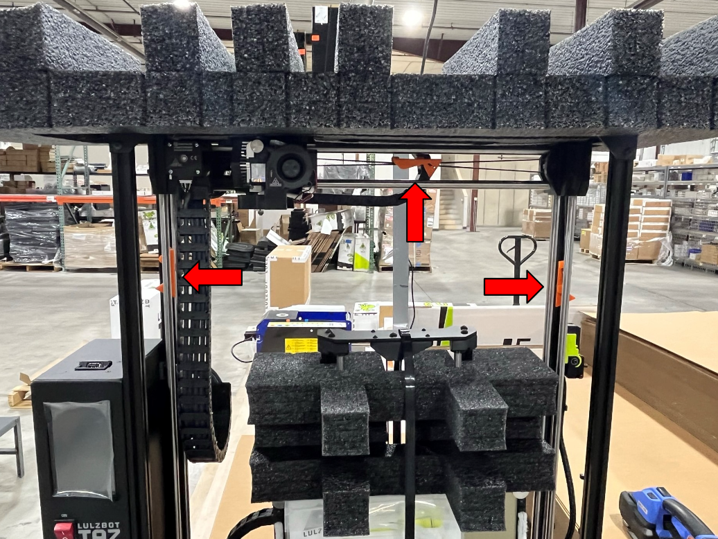
Slide the tool head al the way to the left side of the X axis, then place the top endcap foam [SH-PA0060] on the top of the chassis making sure it aligns with the bottom foam. You may need to move the X axis to get the foam on
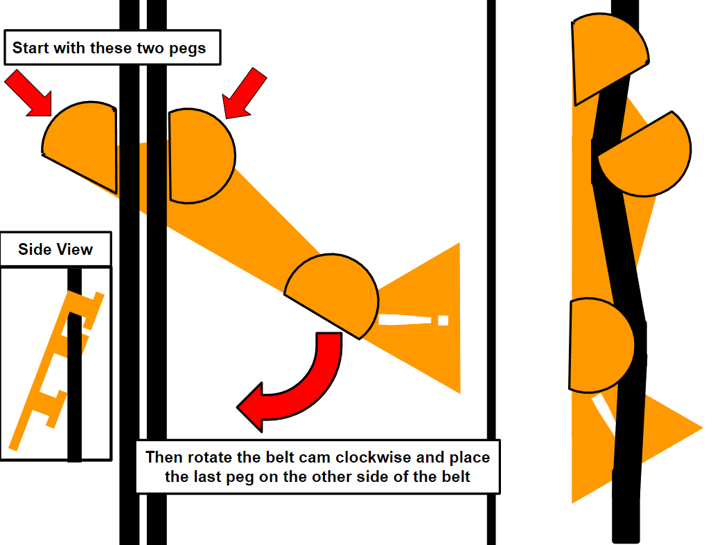
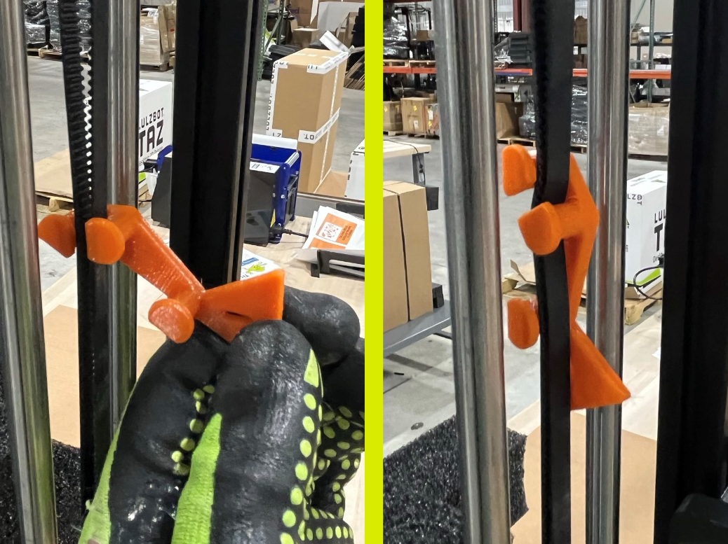
Now use 3x shipping belt cams [PP-GP0635] and place them on the X axis, left Z axis and right Z axis.
To place these parts slide the two top pegs around the belt. While keeping the two top pegs around the belt, twist the belt cam clockwise and slide the bottom peg behind the belt and place it on the other side of the belt.
Repeat for the X axis and left Z axis.
Place the NA power cord [EL-CA0030] inside the slot to the left of the large slot in the top endcap foam.
Now place the Pro XT tool kit inside the large slot in the top endcap foam.
Then place the USB 2.0 A/B cable [EL-CA0063] inside the slot to the right of the large slot in the top endcap foam.

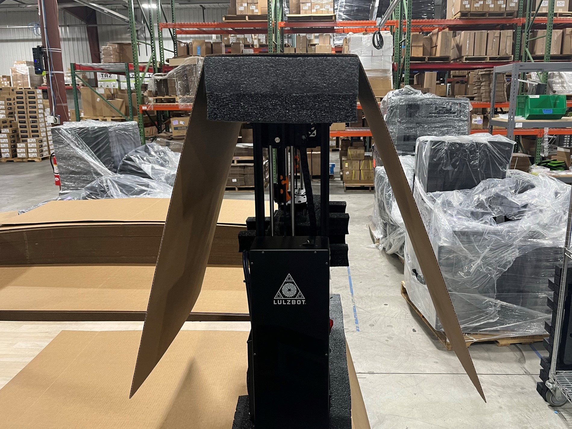
Place a cardboard sleeve [SH-PA0063] over the printer, then fold the two tabs on the bottom sleeve under the top sleeve.
Then make sure the bottom sleeve is aligned with the two red marks on the top of the table and that the bottom foam is aligned with the right edge of the table.
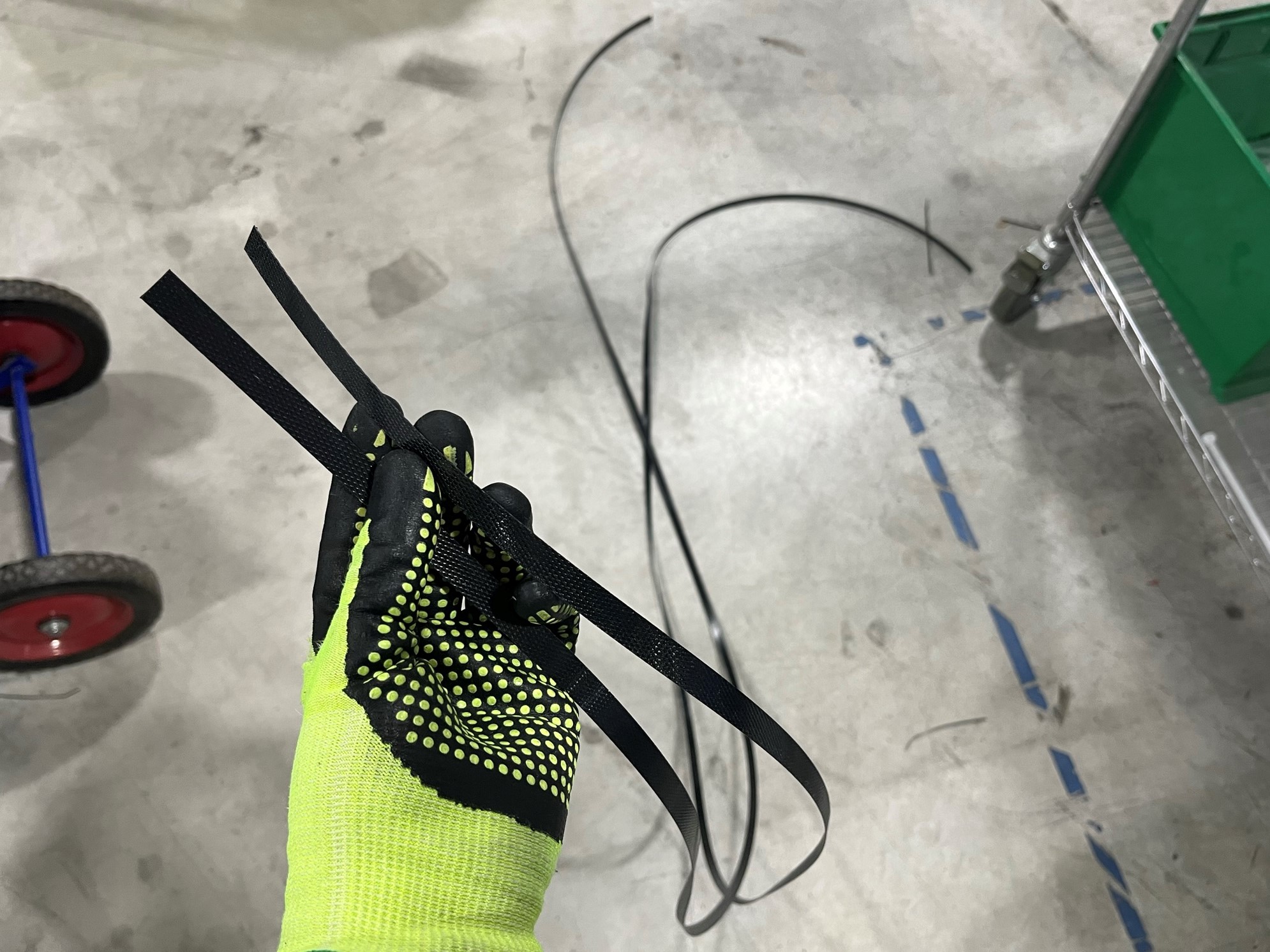
Now cut the black poly strapping [SH-PG0080] to the XT length you will need two of these. The tool kit tables will have the markings on them.
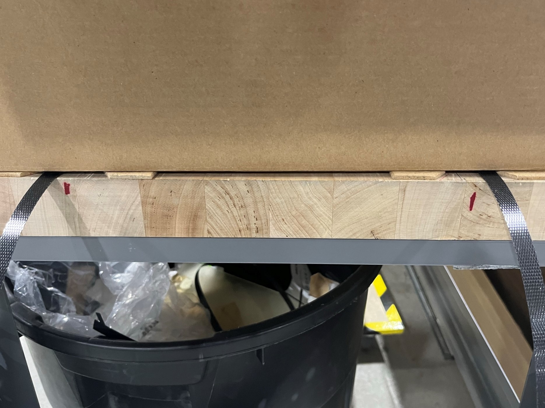
Once the straps are cut slide them under the bottom sleeve by the two middle red marks on the side of the table.
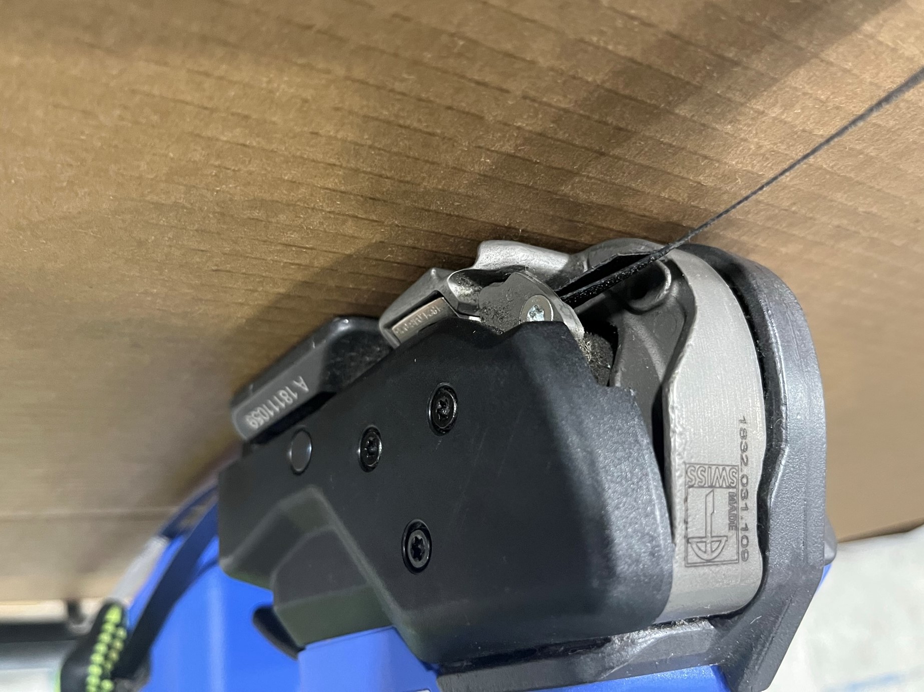
Starting with one strap wrap it around the printer and have the over lapping section in the middle of the front side. Use the Orgapack auto strapping tool to tighten, seal and cut the strapping. Don't over tighten, stop when the strap is sinking into the cardboard.
Repeat for the second strap, while tightening this one watch the edges of the sleeve and try to align them.


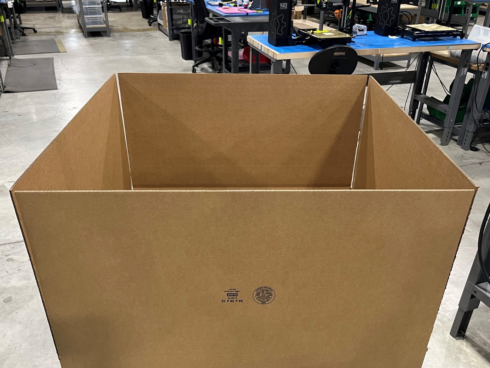
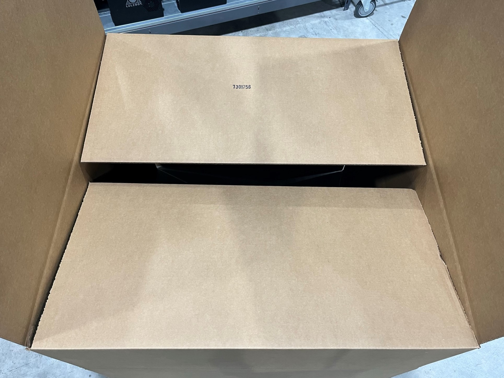
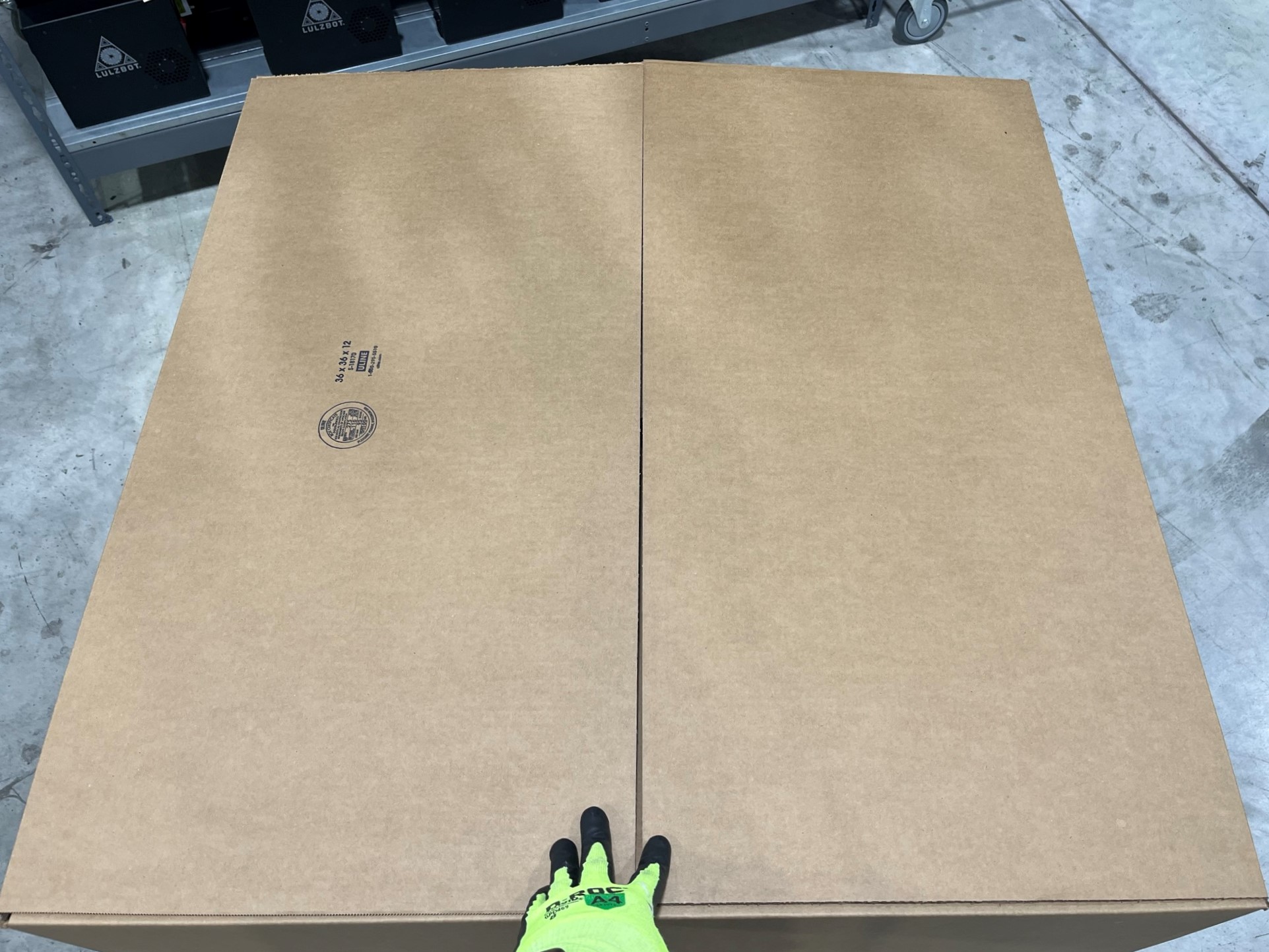
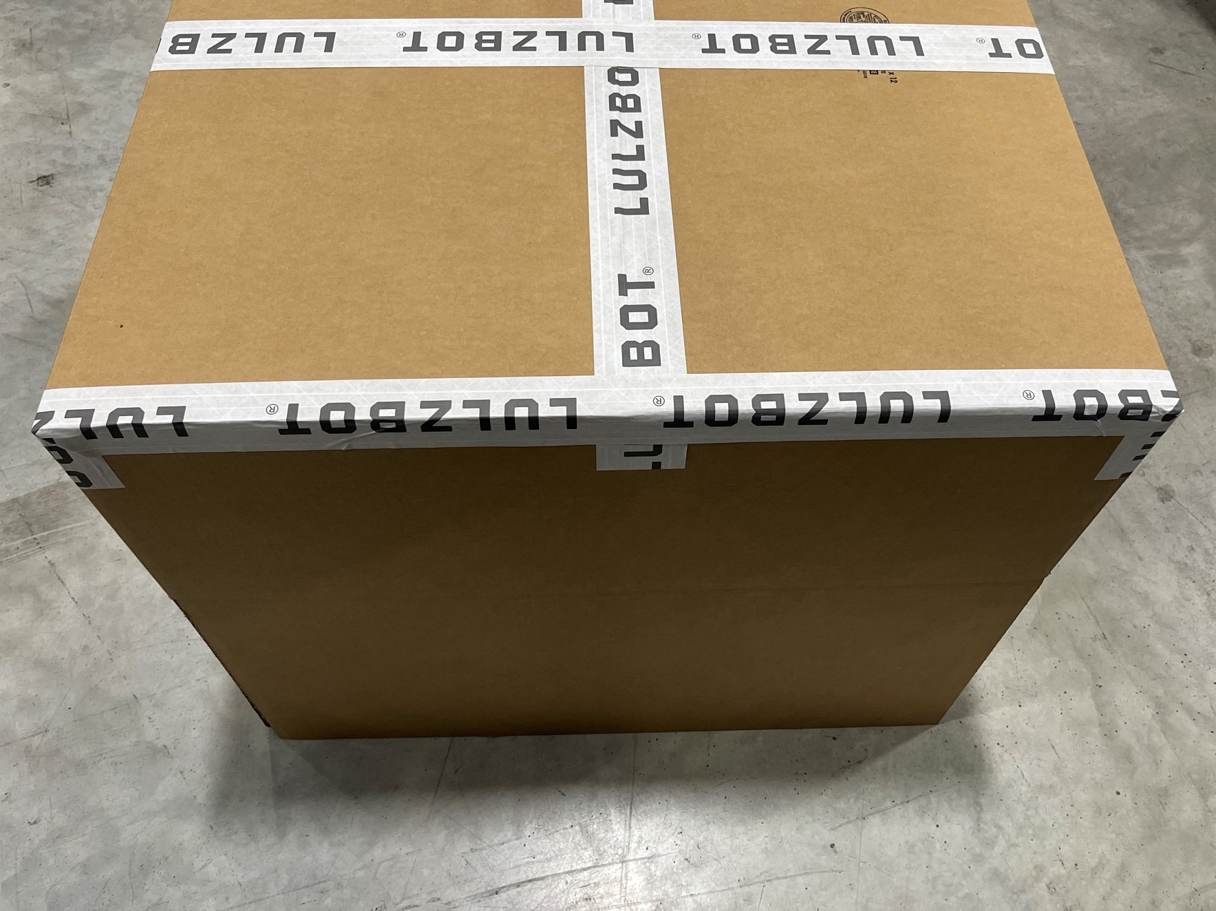
Open the TAZ Pro XT product box [SH-BX0499] and fold the two blank tabs inward followed by the other two tabs.
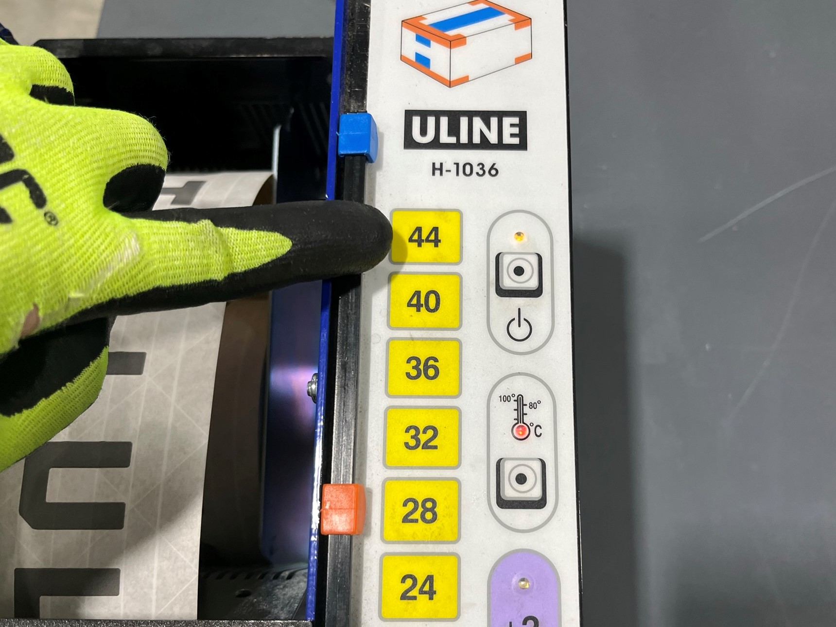
Press the 44 button on the tape machine for all the pieces of tape.
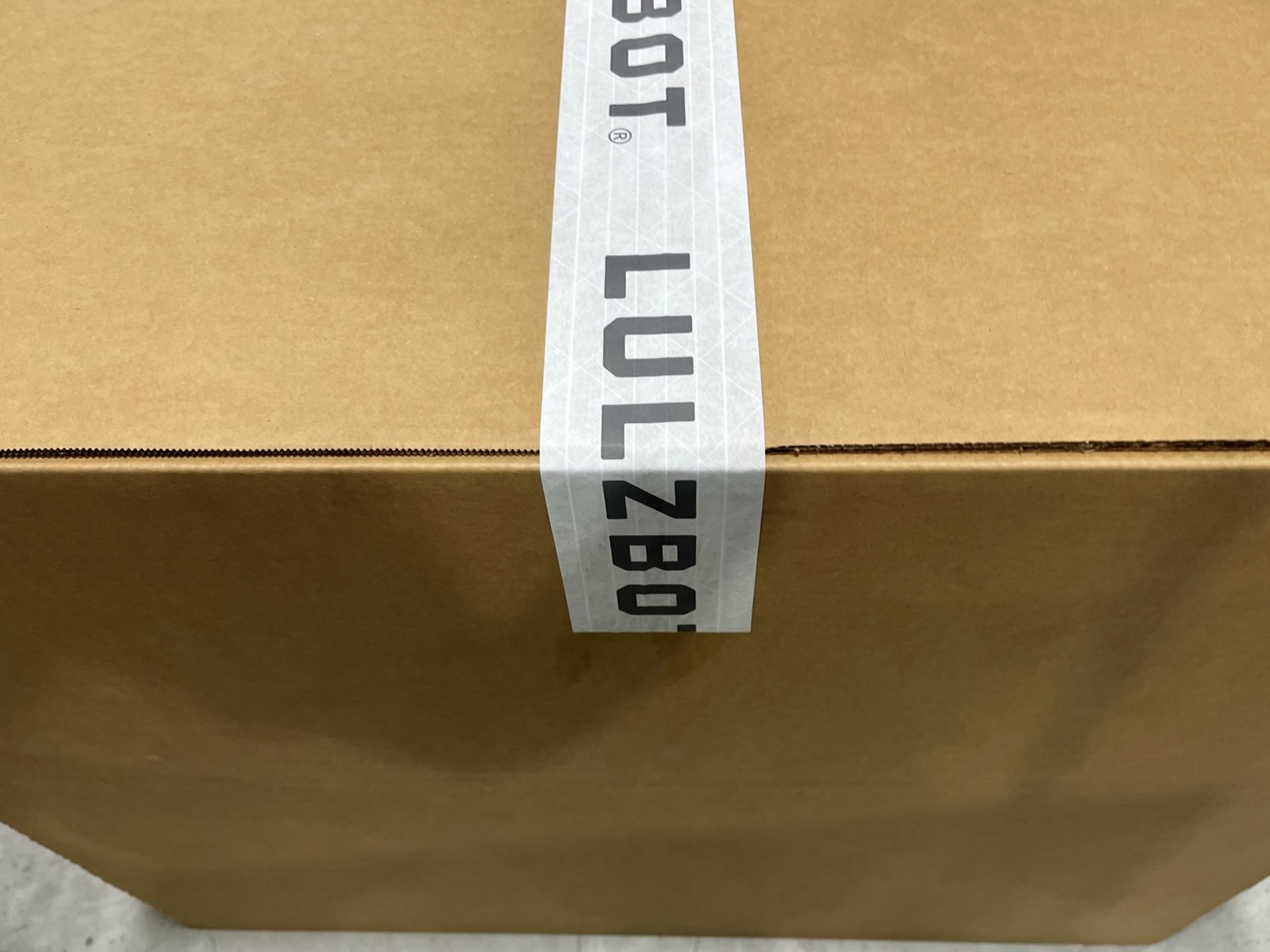
Place the tape over the seam of the two tabs and fold the end over the side of the box.
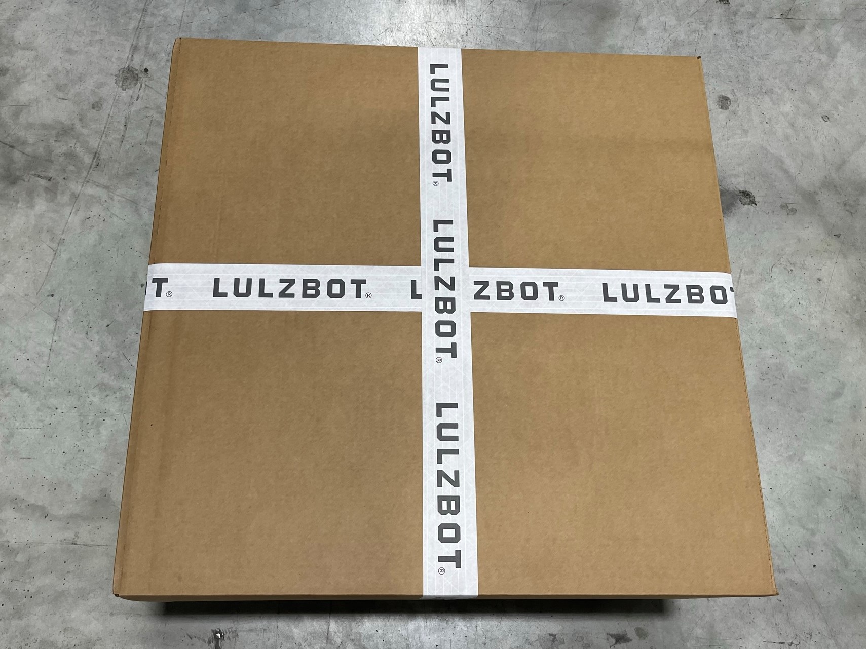
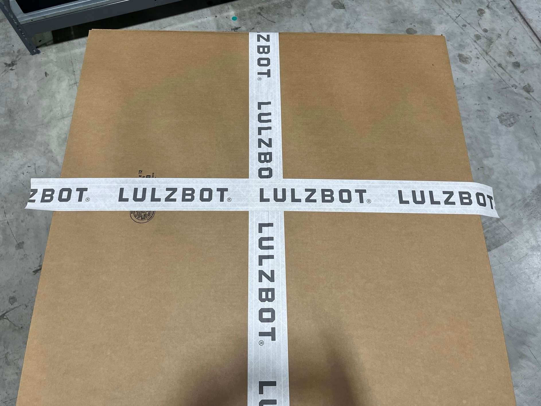
Then repeat the process so that there is a "X or +" on the face of the box.
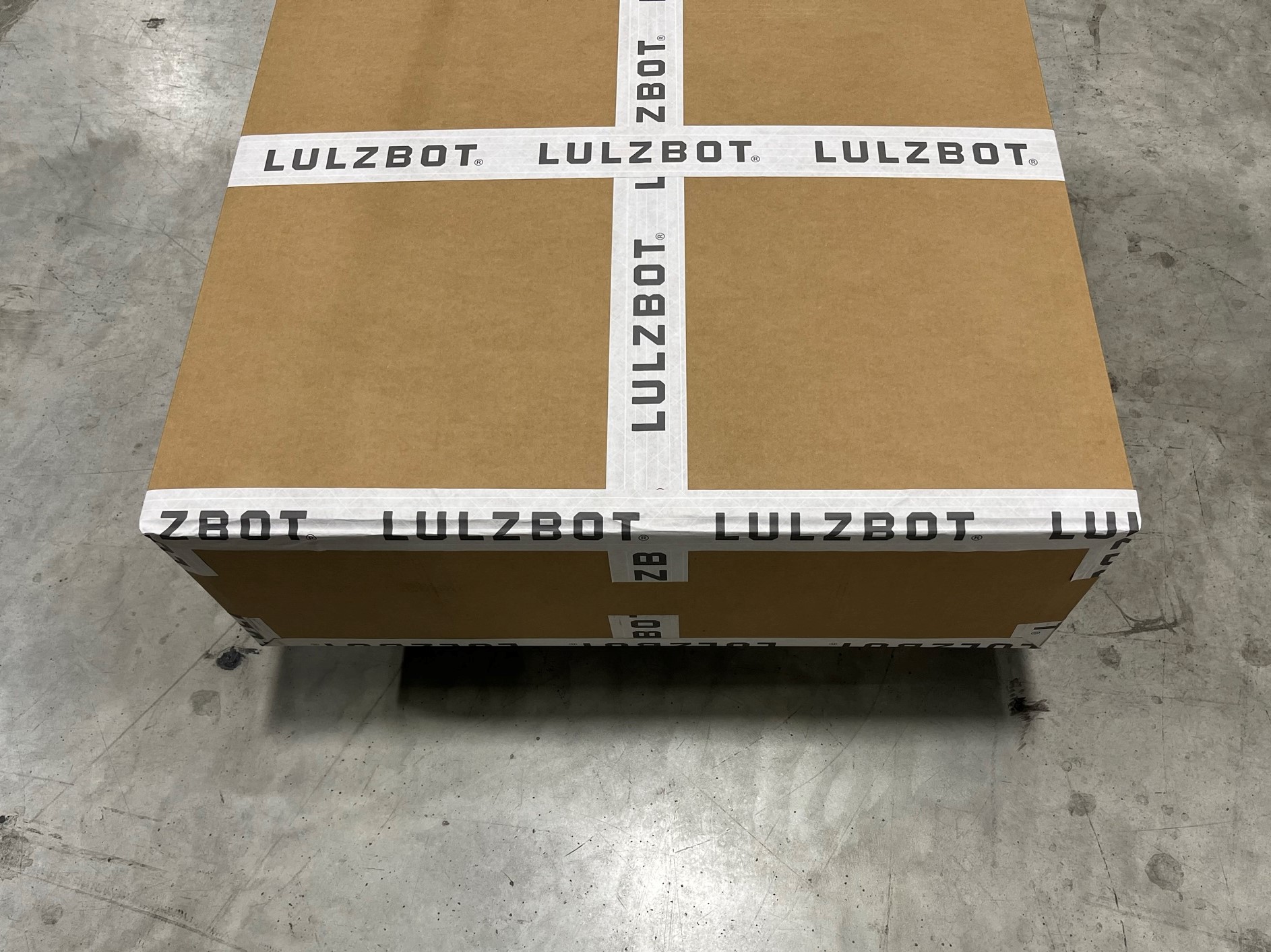
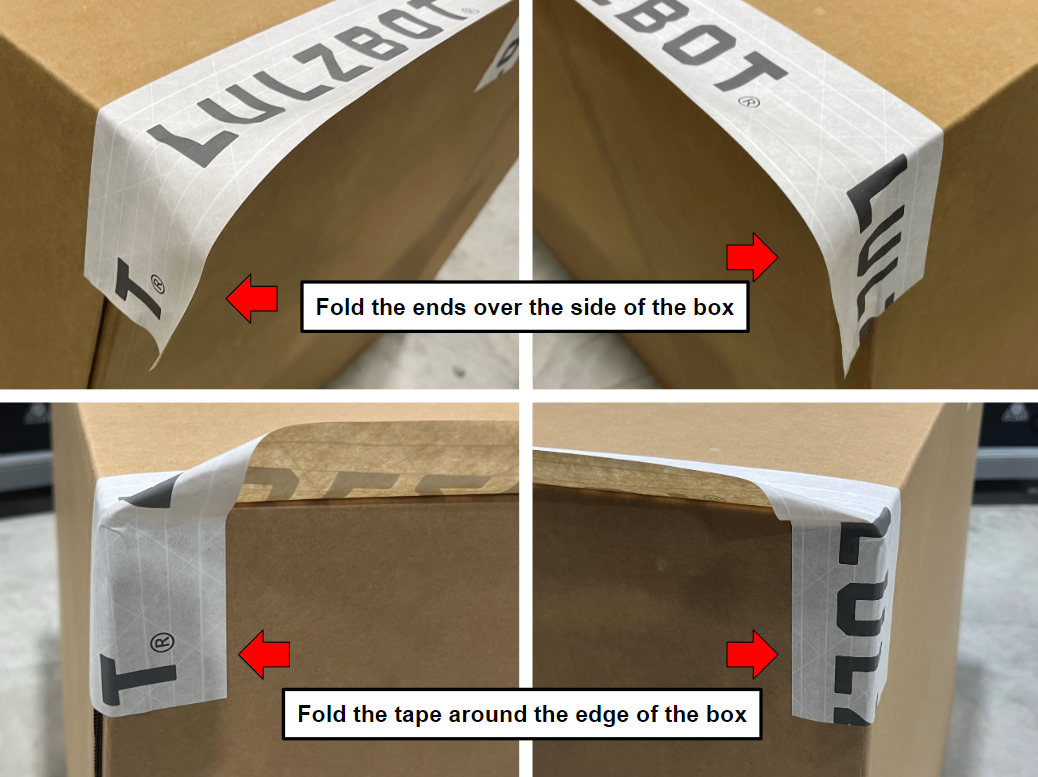
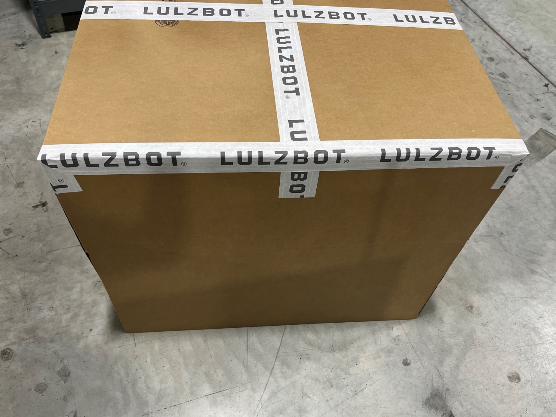
Now place a section of tape over the edge of the box and fold the ends around the corner of the box. Make sure its on the side that has the edges of the two top flaps.
Once the ends are wrapped around the corner fold the tape over the edge of the box. Repeat is this process for the opposite side of the box.


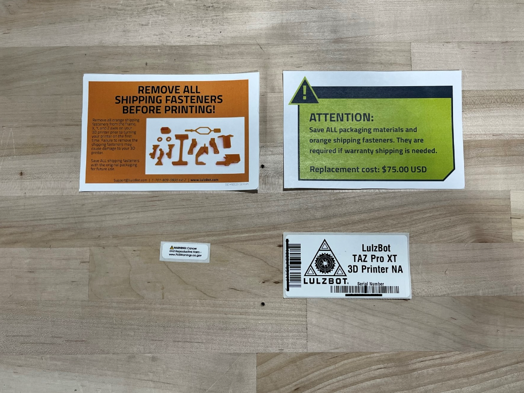
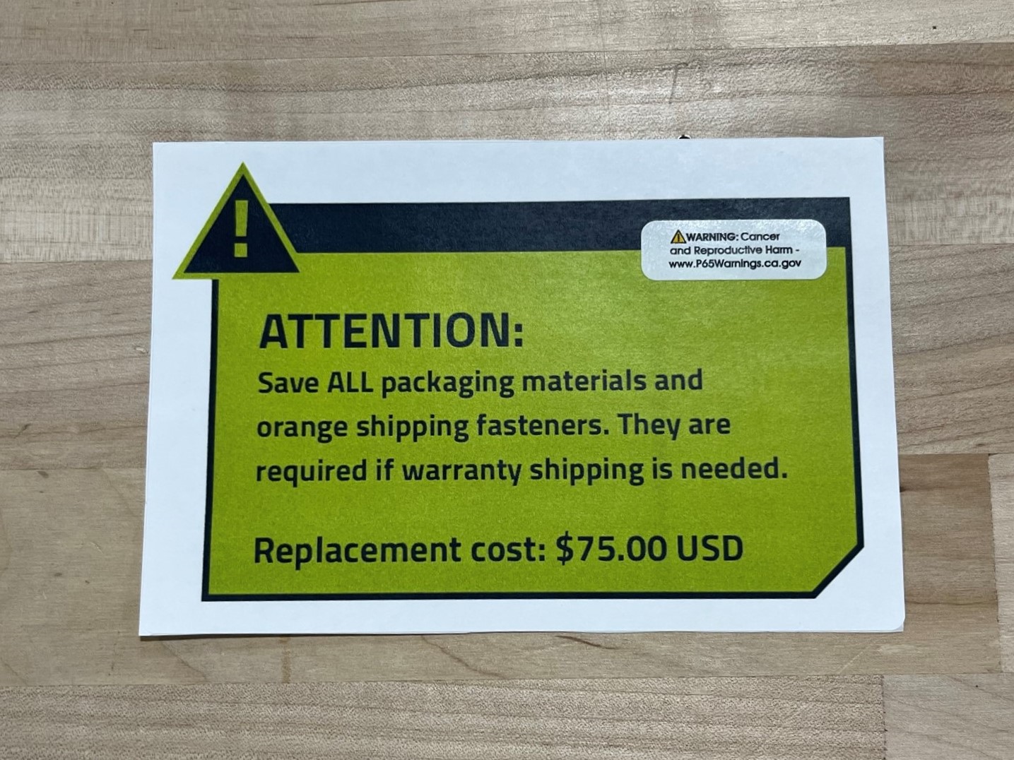
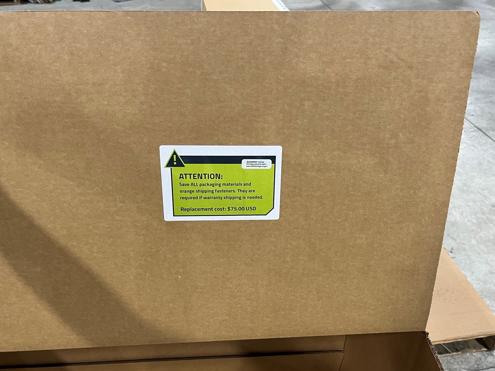
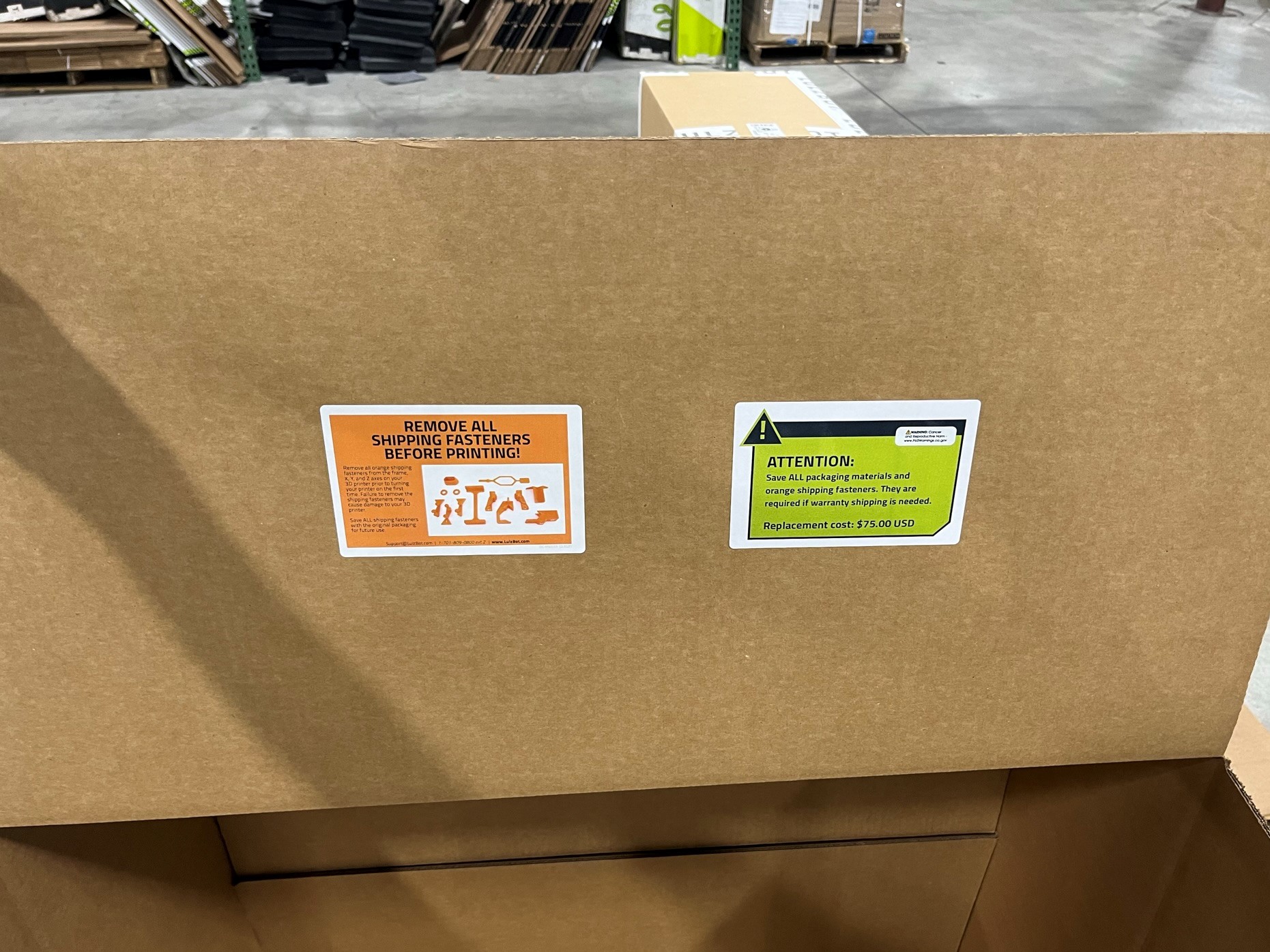
Place the P65 warning label [DC-LB0174] on the save your packaging sticker [DC-LB0118] in the top right corner. Then flip the box over and place the save your packaging sticker on one of the tabs of the box.
On the same tab place the packaging material removal guide [DC-MS0115].
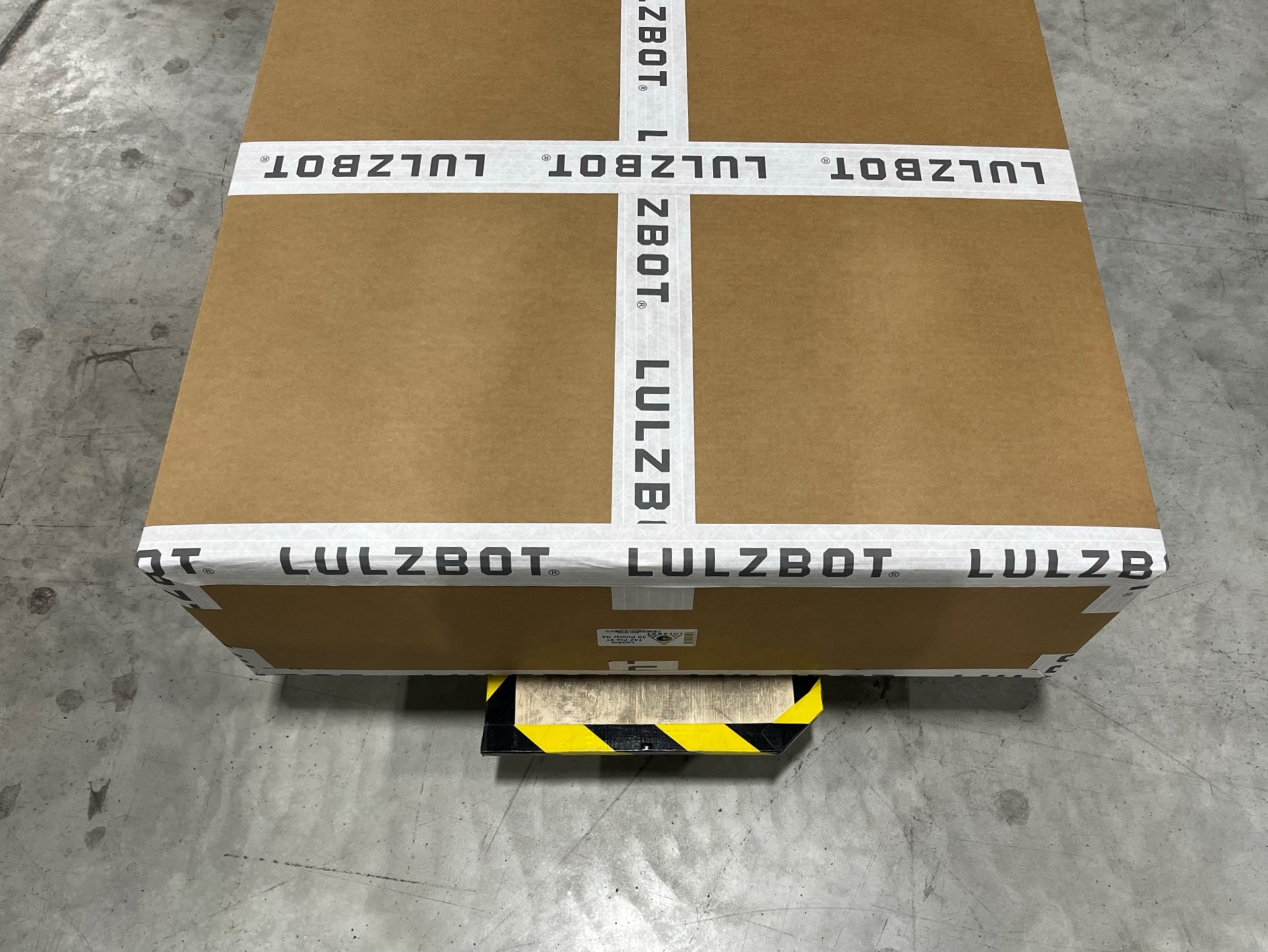
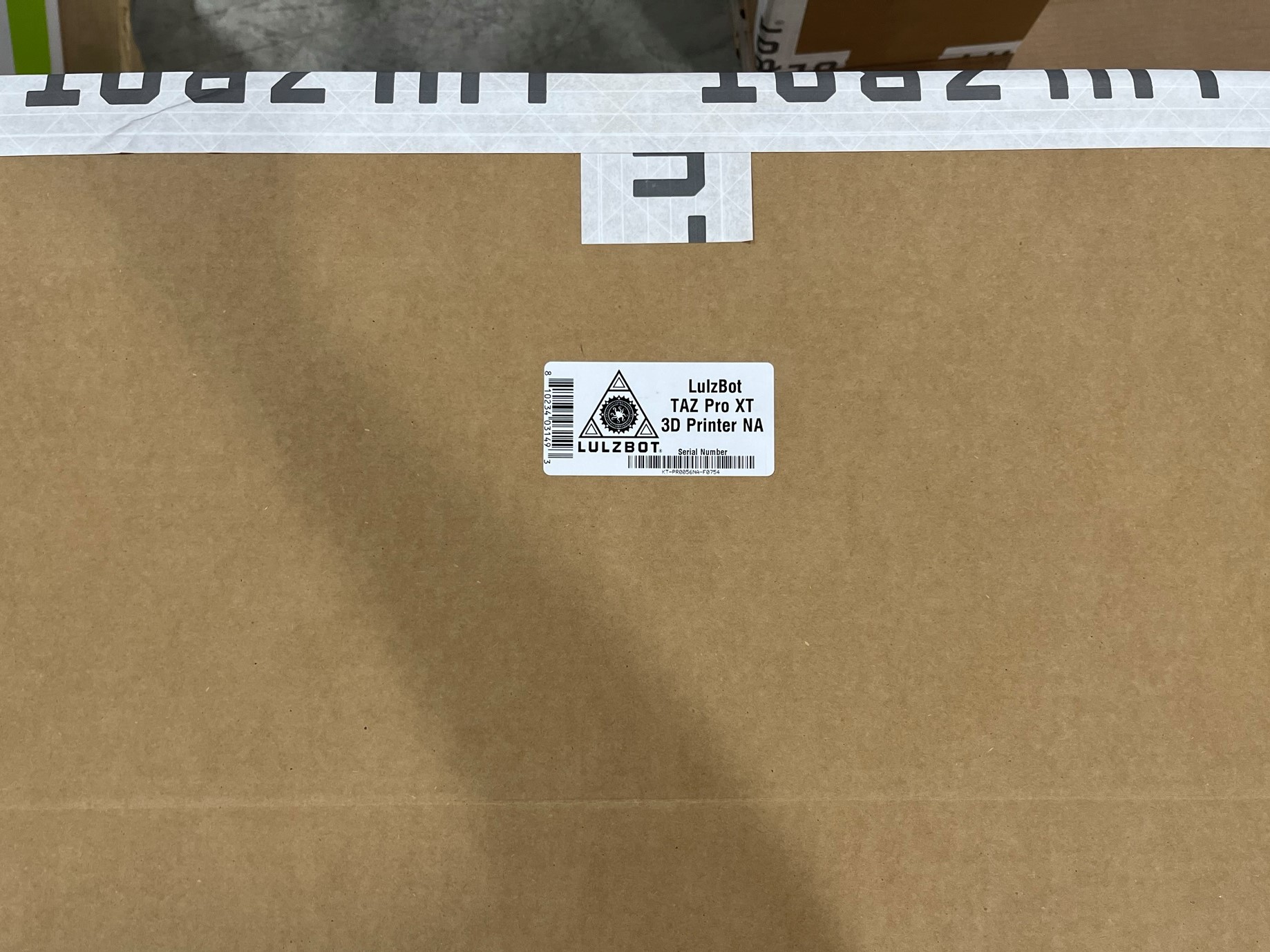
Then rotate the box so that you can see the outside of the box, and on the same side that the other stickers are on place the serial number sticker on the box under the end of the tape.
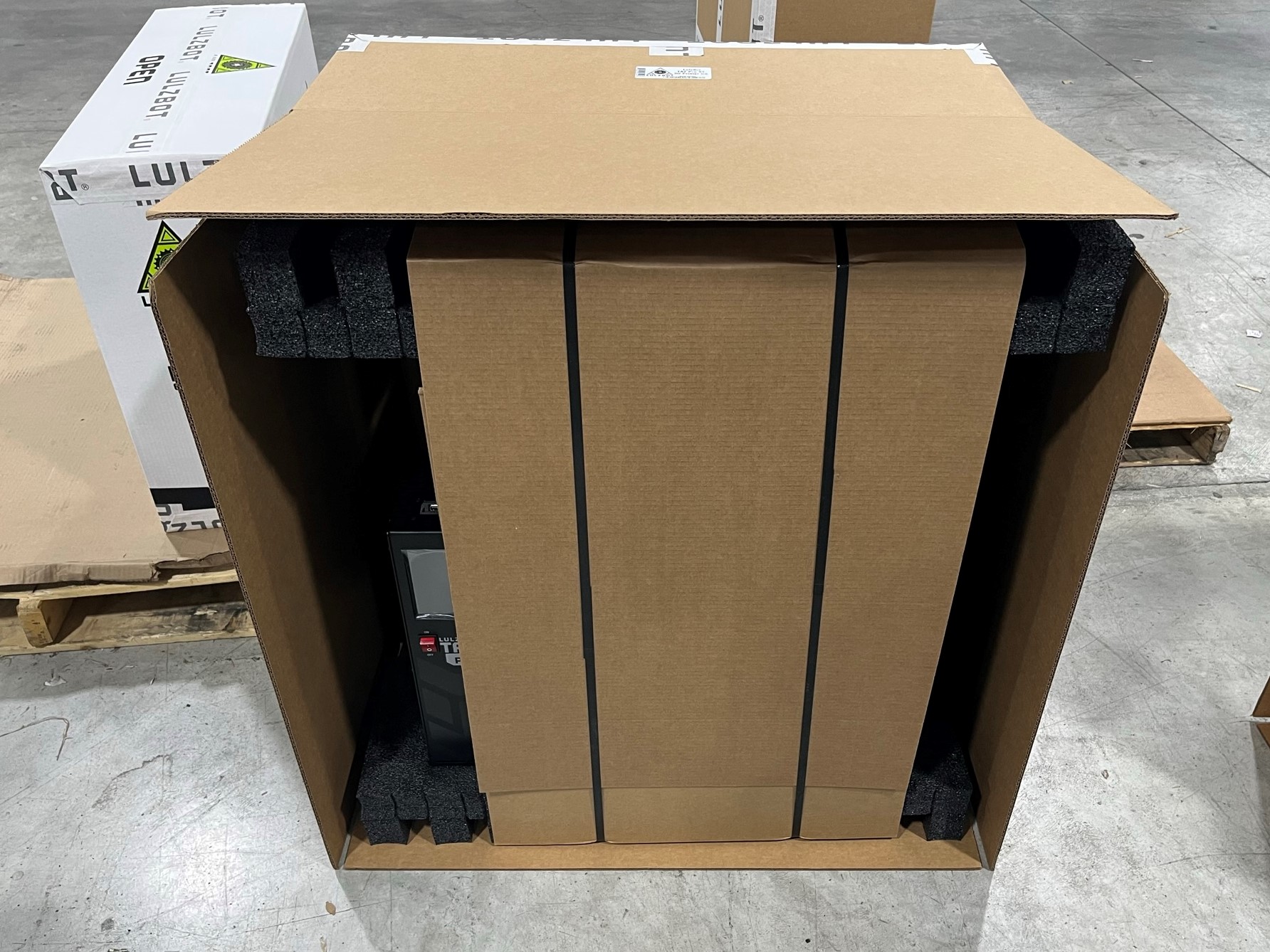
Place the box on the ground with the serial number sticker on top and fold the top tab up.
Then take the printer and set it on the bottom tab of the box, then slide it all the way into the box.
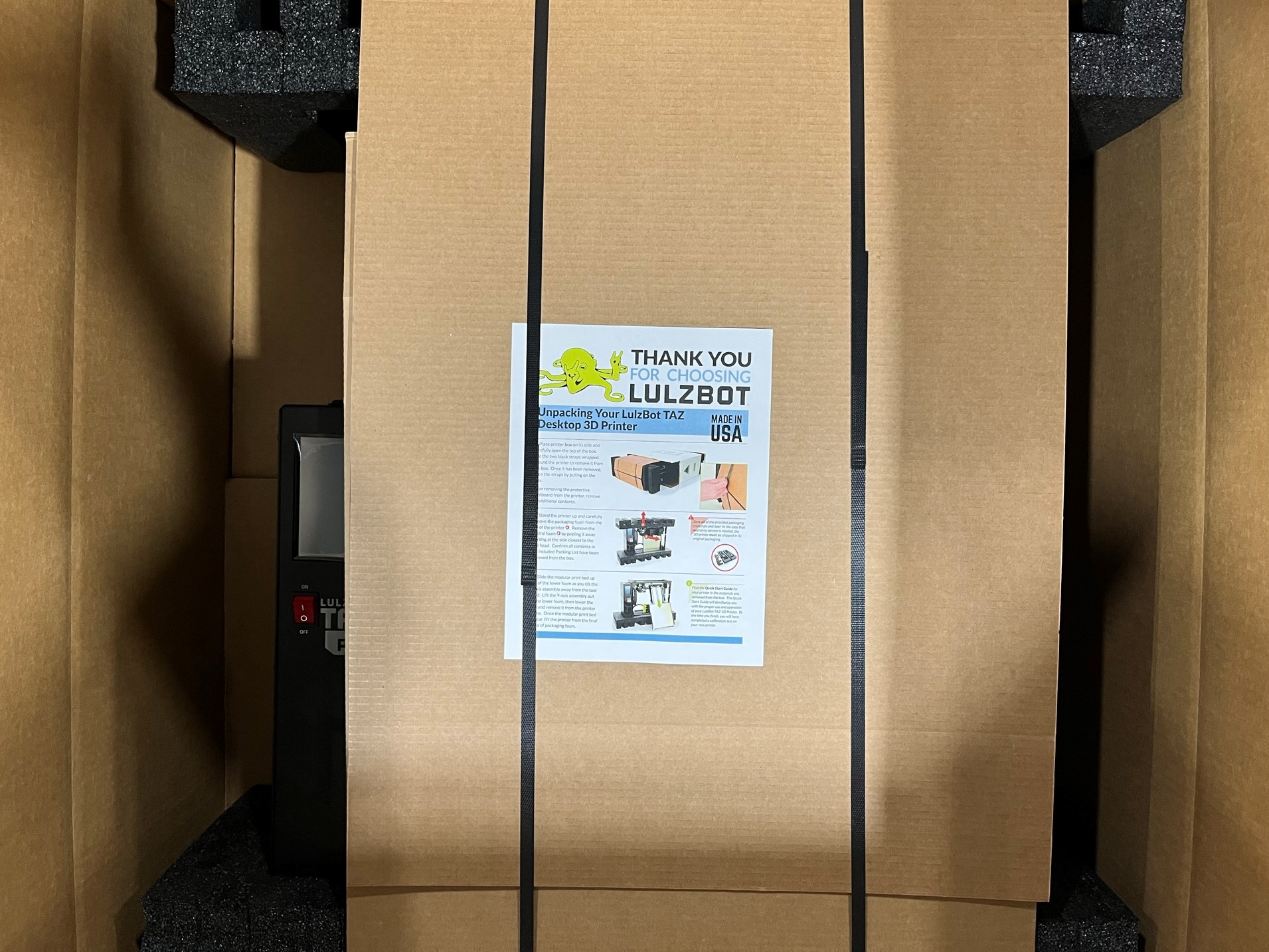
Once the printer is inside the box place the TAZ Pro XT unpackaging guide under one of the straps.

Repeat the taping process to close the box up