Open HardwareAssembly Instructions
Guides for installation and assembly of the LulzBot line of products made by FAME 3D LLC.
Guides for installation and assembly of the LulzBot line of products made by FAME 3D LLC.
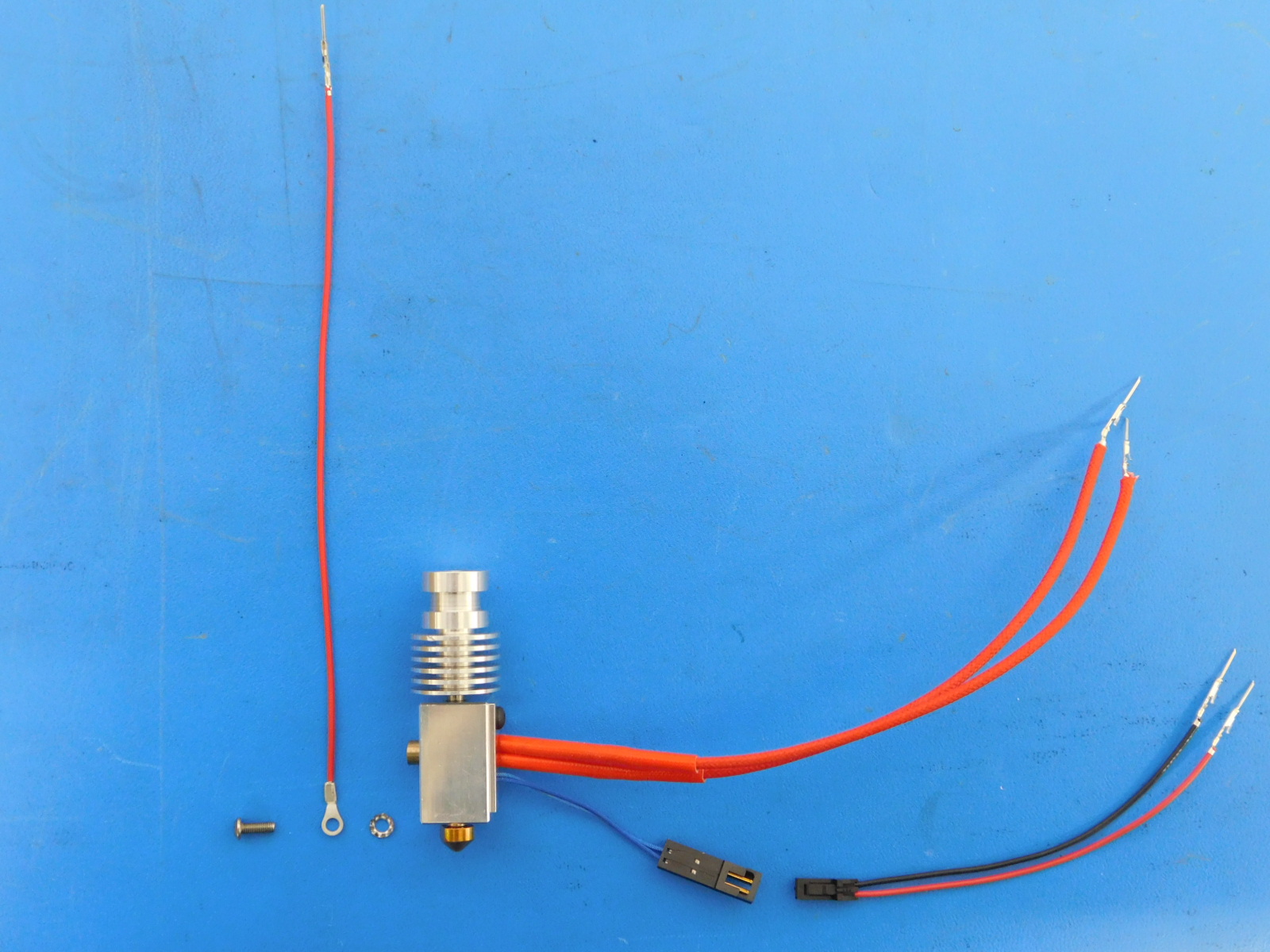
Gather parts:
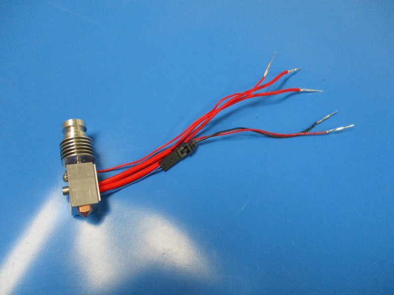
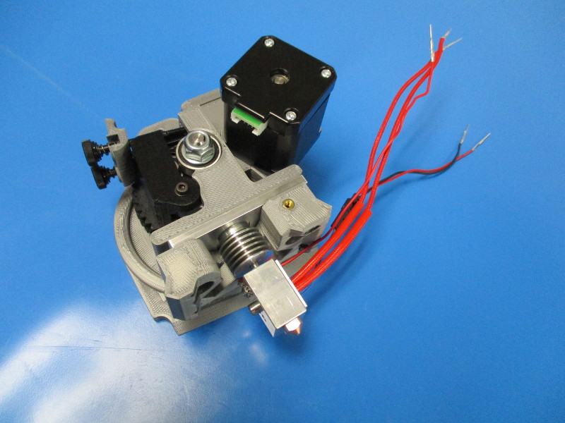
E3D MOARstruder Hot End, 3.0mm Filament, 1.2mm Nozzle, assembled and crimped (AS-HE0015)
MOARstruder Thermistor Extension Harness (AS-CB0014)
Zero volt sense harness (AS-CB0010)
M3x8 BHCS screw (HD-BT0104)
External star washer (HD-WA0035)
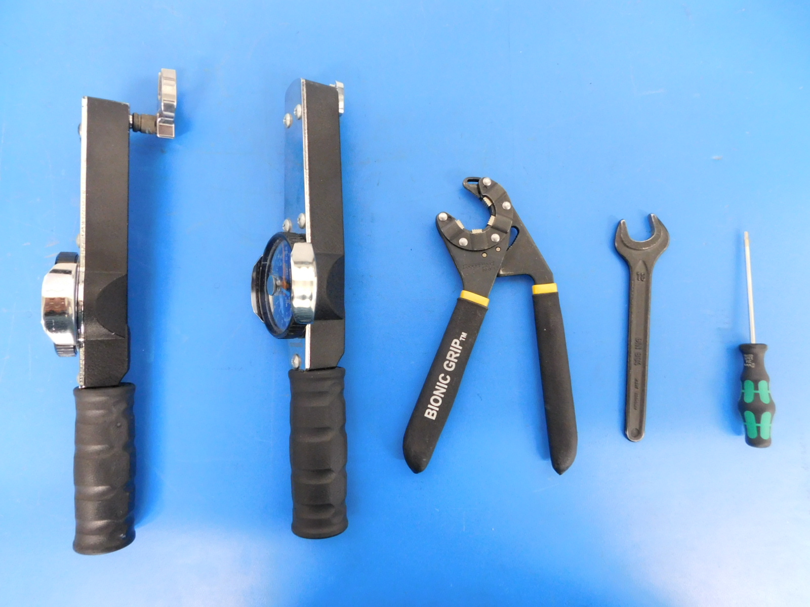
Tools needed:
Dial Torque Wrench (Set to 30 in-lbs and 15 in-lbs)
18mm and 7mm wrench heads
Bionic Grip wrench
18mm wrench
2mm hex driver
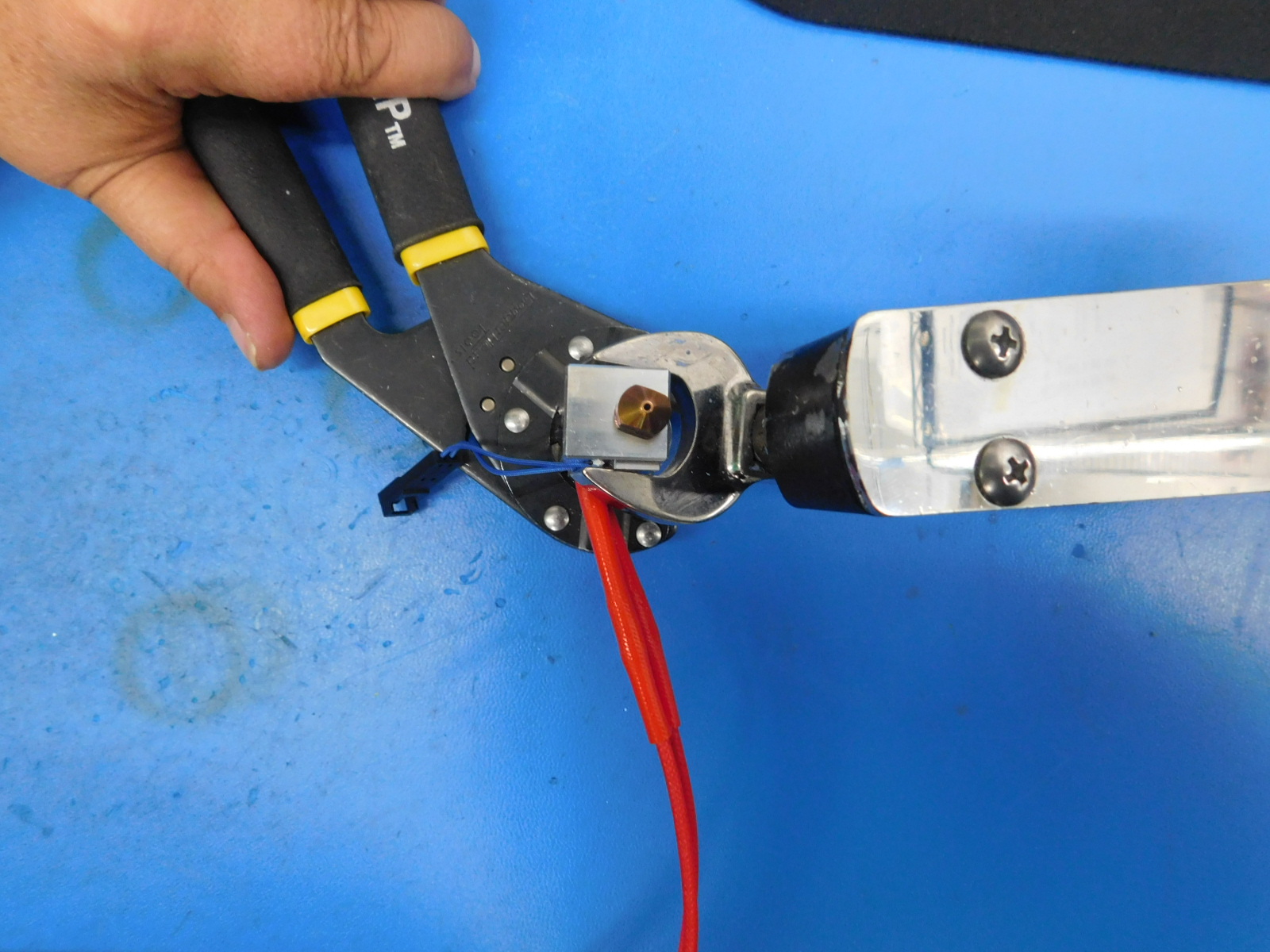
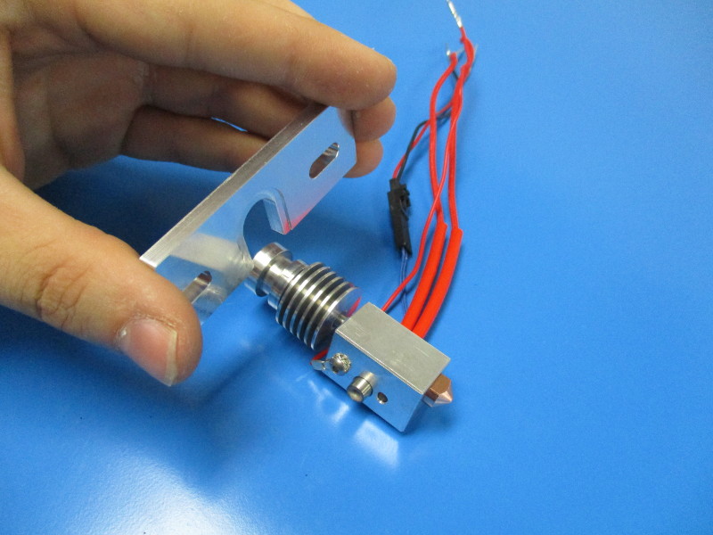
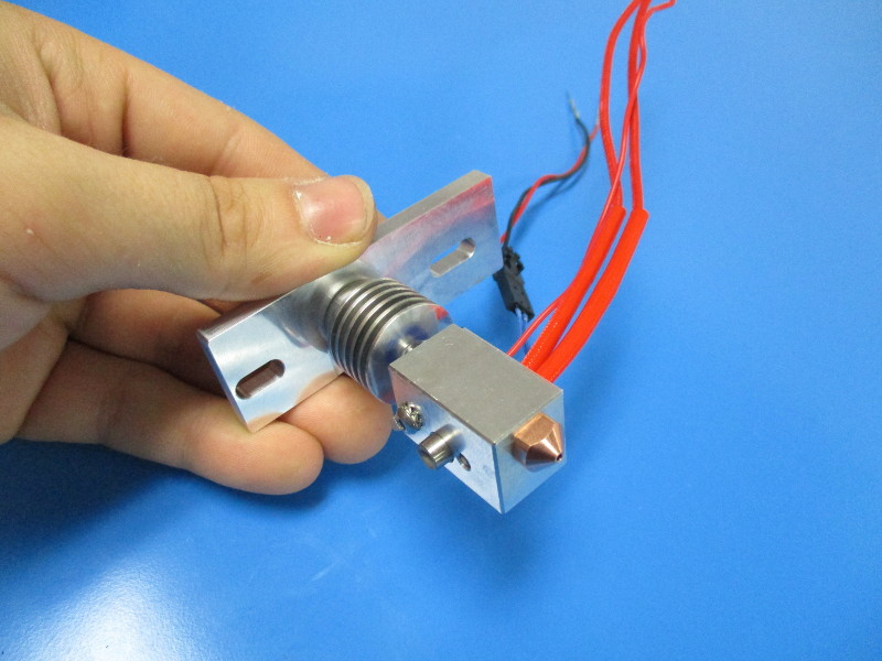
Verify the torque on the Heater Block as shown
Secure the Heat Sink with the Bionic Grip Wrench
Use a Dial Torque Wrench with a 18mm wrench head attachment and torque the Heater Block to 30 in-lbs
Verify the torque on the Nozzle as shown.
Using a 18mm wrench secure the heater block
Use a Dial Torque Wrench with a 7mm wrench head attachment and torque the Nozzle to 15 in-lbs

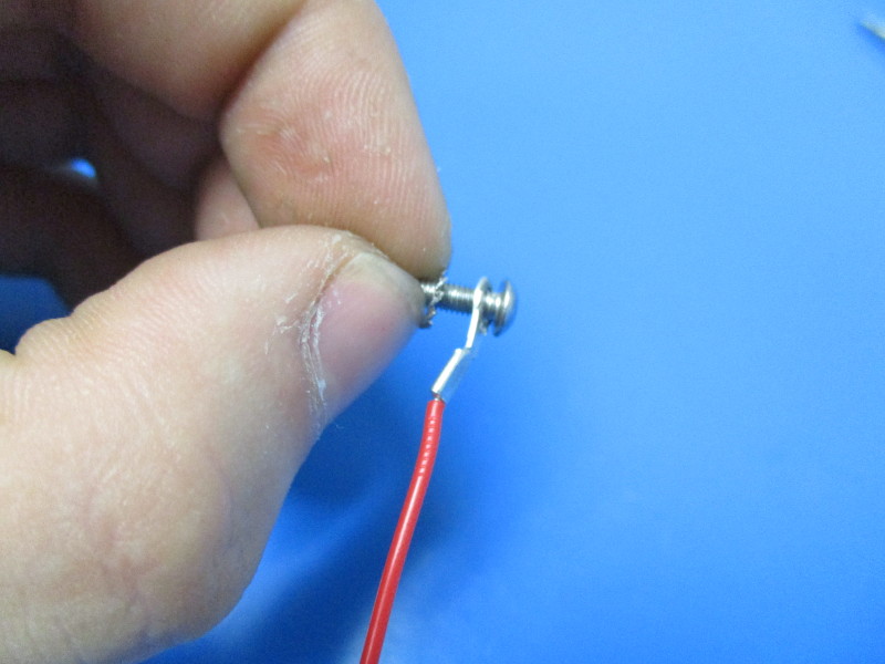
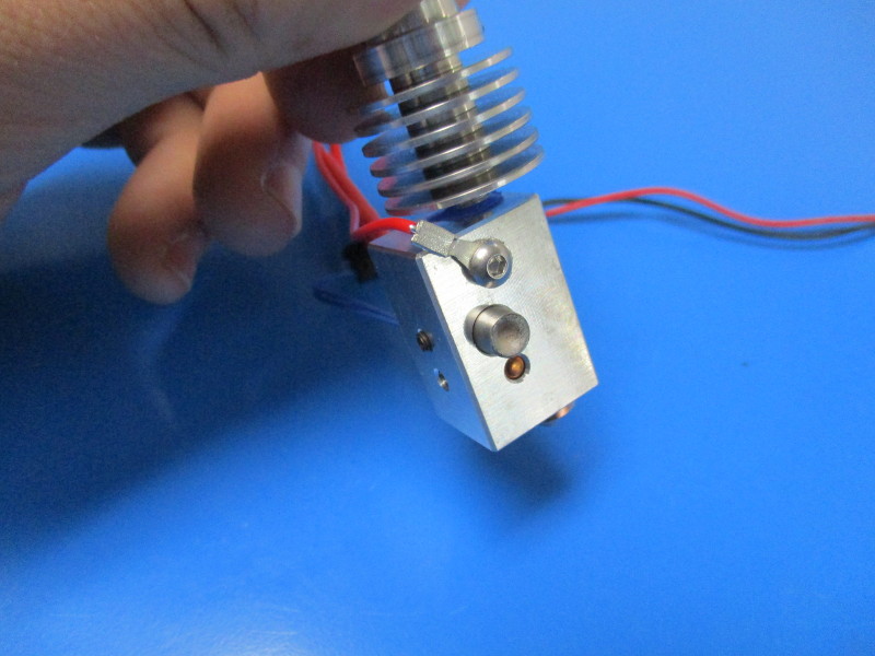
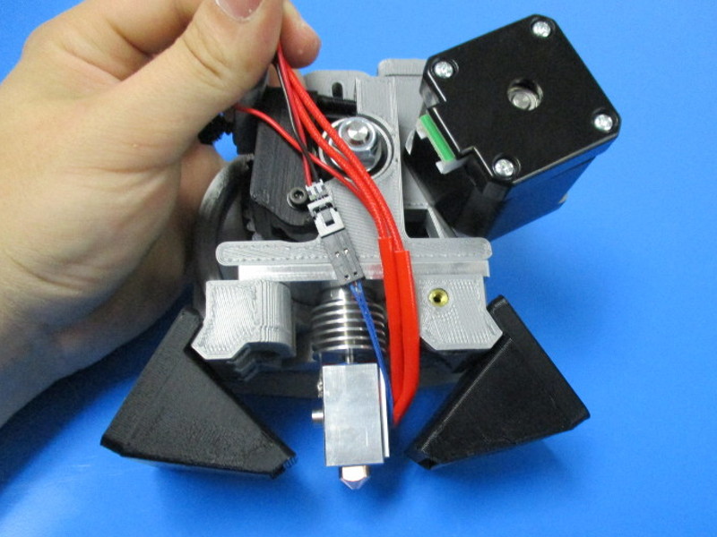
The zero volt sense harness needs to be attached with the external star washer, the zero volt sense harness and the M3x8 BHCS screw in this order
Install onto heater block (note orientation of heater block and direction of wire), torque screw to 3 in-lbs
Ensure the insulation is not touching the heater block
Connect the Thermistor Harness

Gather parts:
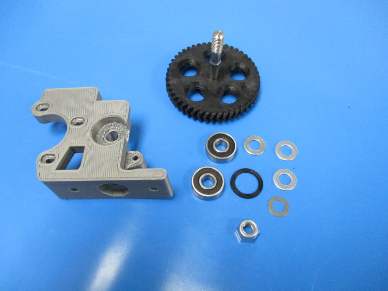
1x- Large herringbone gear, black (AS-TH0020)
2x- 608 bearings (HD-MS0282)
3x- M8 steel washer (HD-WA0006)
1x- Extruder washer (PP-GP0060)
1x- 0.5mm shim (HD-WA0008)
1x- M8 nyloc nut (HD-NT0002)
1x- Extruder body (AS-TH0036)
Tools needed:
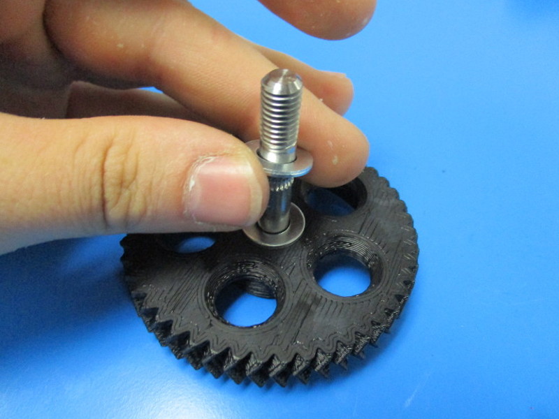
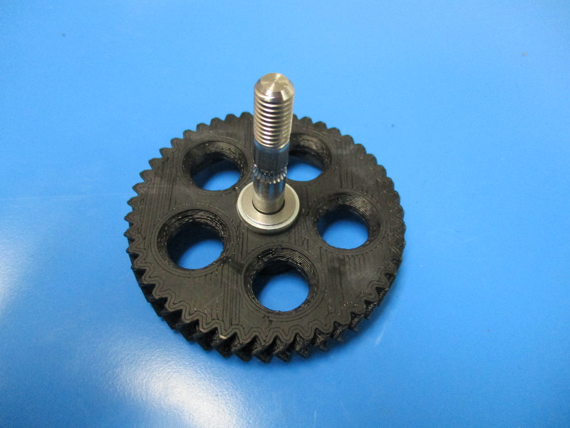
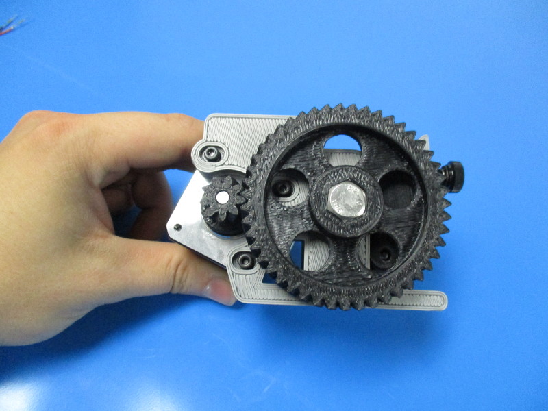
Place M8 stainless steel washers over the hobbed bolt
Place 0.5mm shim over hobbed bolt
Insert extruder washer into bearing slot (note orientation of the extruder body)
Insert 608 bearing into bearing slot
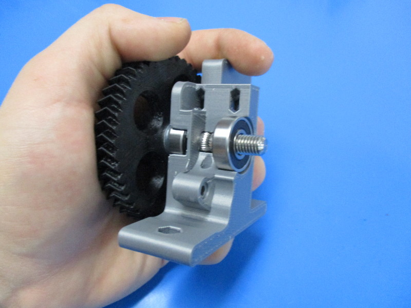
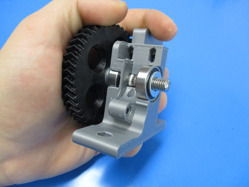
Slide the hobbed bolt through the 608 bearing and the extruder body
Place 608 bearing over the threaded portion of the hobbed bolt
Place M8 stainless steel washer over the hobbed bolt
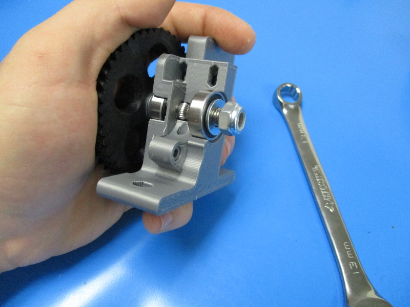
Thread M8 nyloc nut onto the hobbed bolt
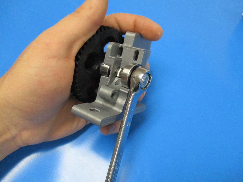
Tighten M8 nyloc nut with a 13mm wrench
Tighten until m8 washer is snug and doesn't move on it's own
Gather parts:
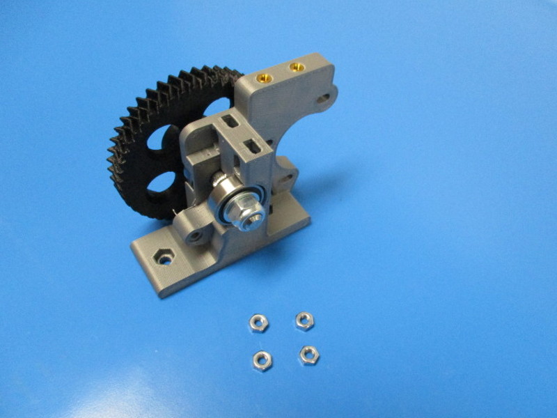
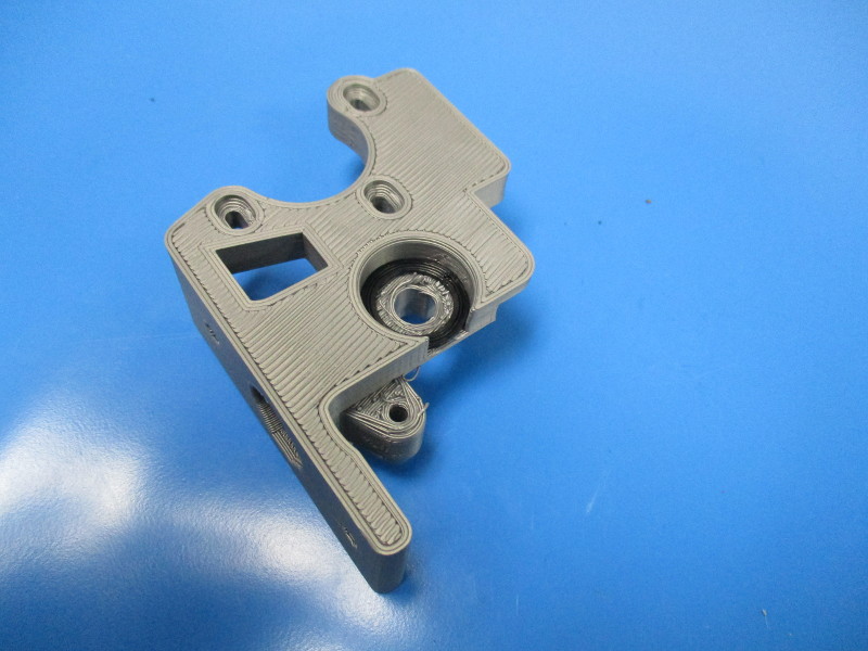
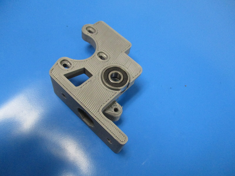
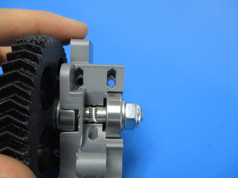
Insert 2x- M4 nut into the slots on the top of the extruder body
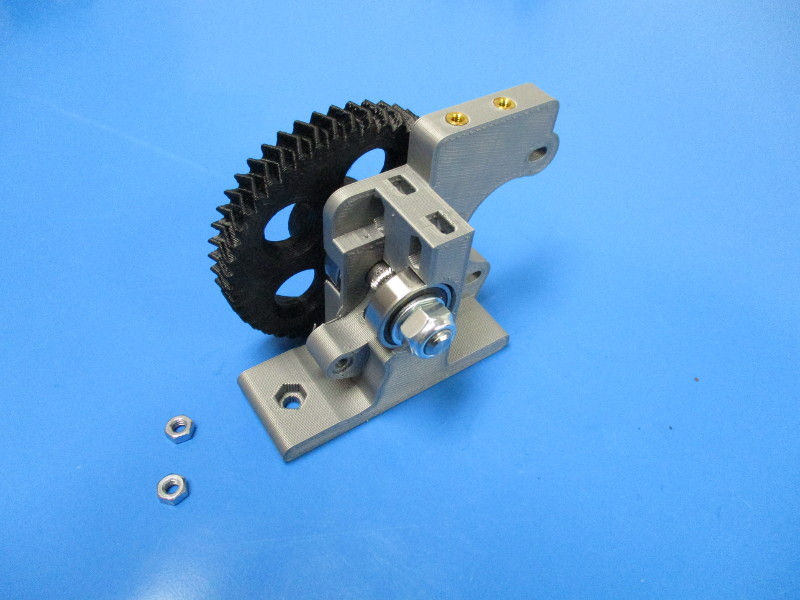
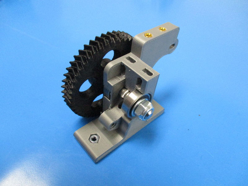
Insert 2x- M4 nuts into the base of the extruder body

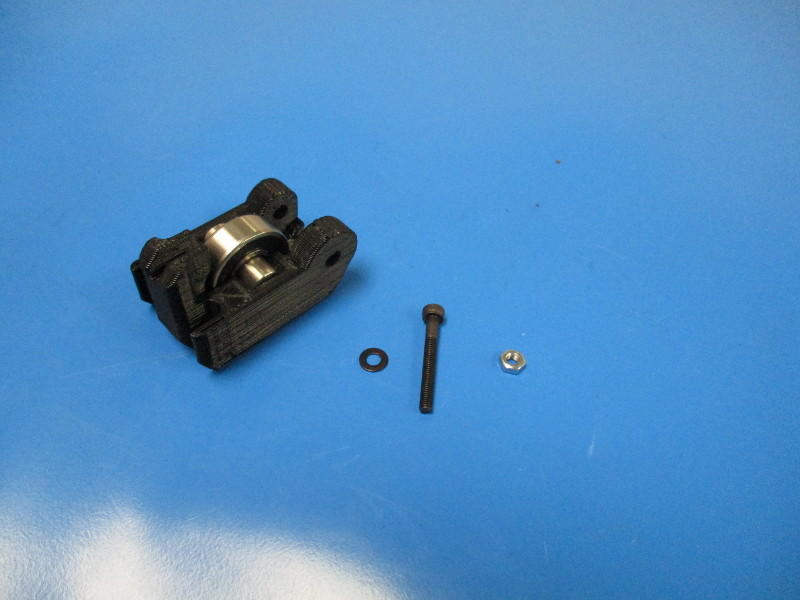
Gather parts:
idler block (AS-TH0028)
M3x25 SHCS (HD-BT0041)
M3 black oxide washer (HD-WA0038)
M3 nut (HD-NT0004)
Tools needed:
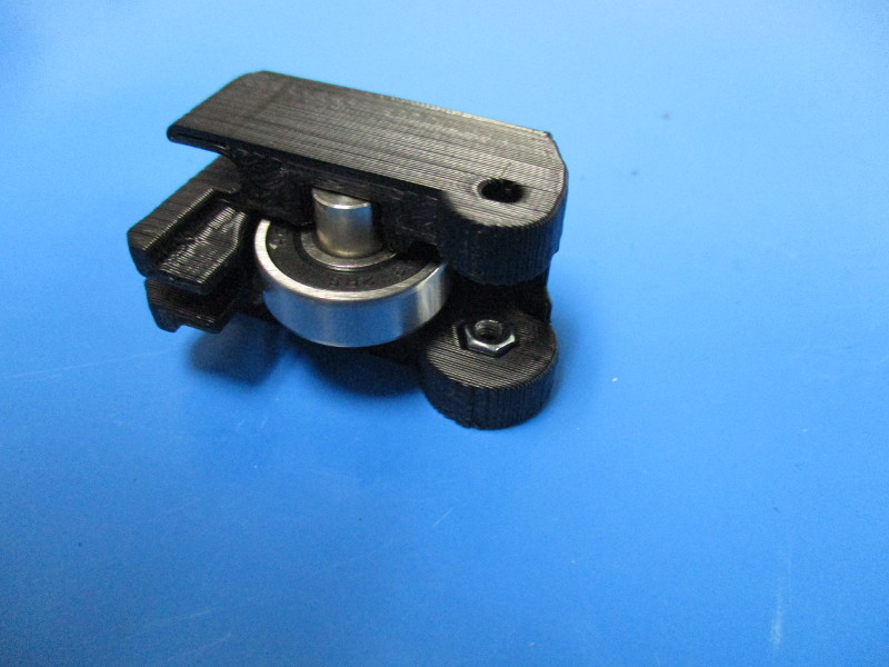
Press the M3 nut into the idler block so that it is captured in the nut shaped socket
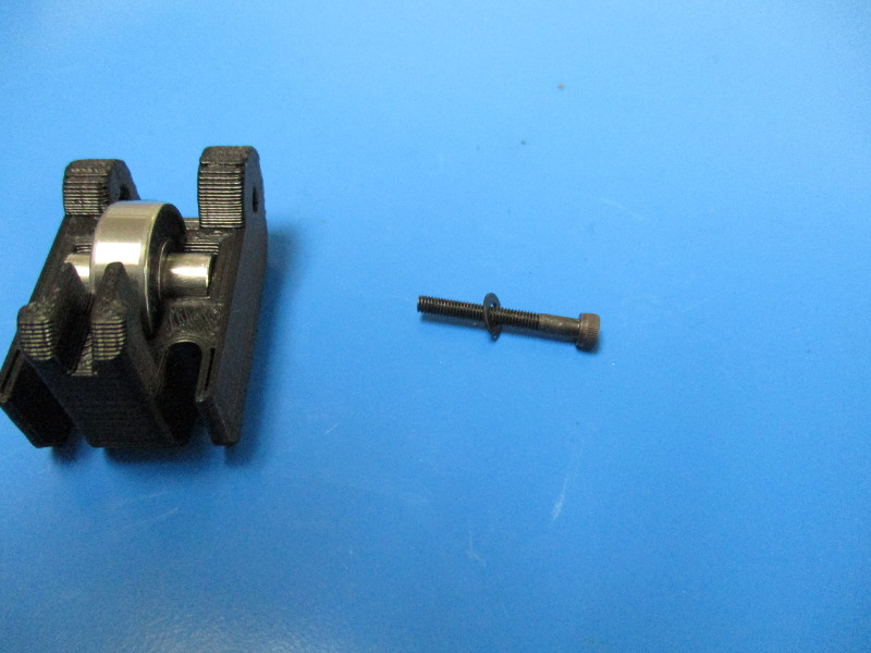
Add M3 black oxide washer to M3x25 SHCS
Thread the M3x25 SHCS through the idler to capture the M3 nut
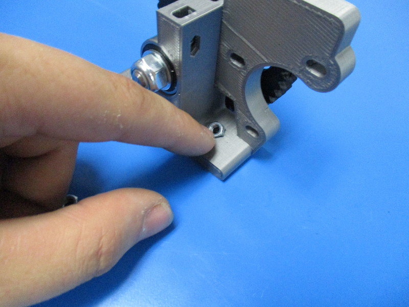
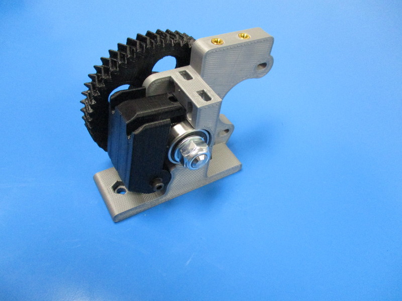
Install idler block onto extruder body
Torque to 3in*lbs


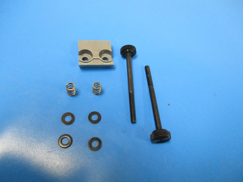
Gather Parts
1x- extruder latch (PP-GP0275_v2.2)
4x- M4 black oxide washer (HD-WA0039)
2x- compression spring (HD-MS0027)
2x- M4x55 thumb screw (AS-TH0005)

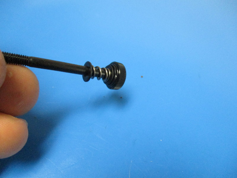
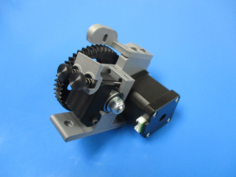
Assemble thumb screw in order: thumb screw, washer, spring, washer
Repeat to make a second
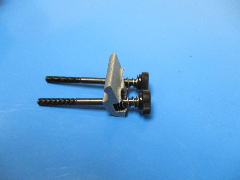
Place assembled thumb screws into Extruder latch
Install onto extruder body (note orientation of latch)
Gather Parts:
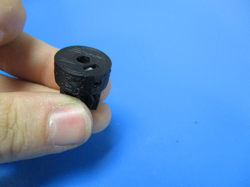
Small herringbone gear, black (PP-GP0062)
M3 set screw (HD-BT0012)
M3 nut (HD-NT0004)
Tools needed:
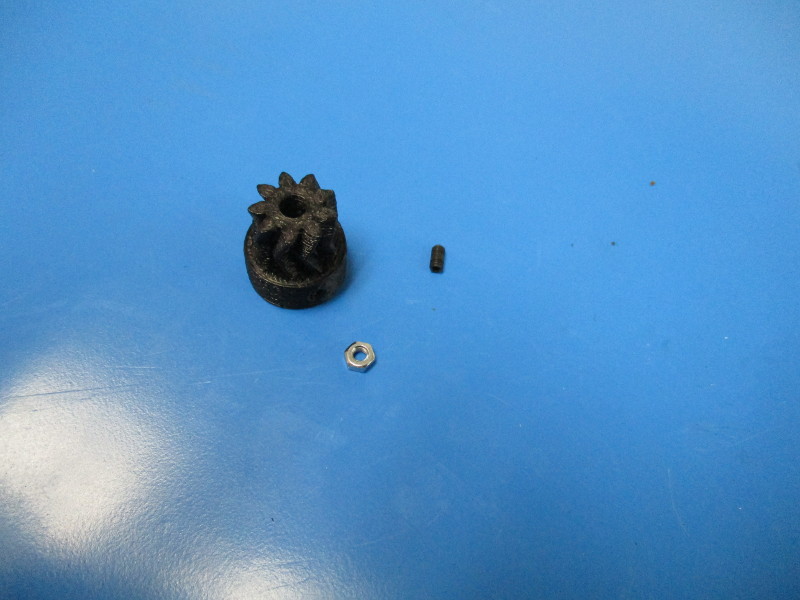
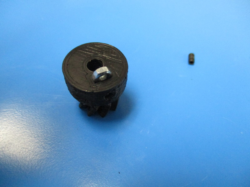
Press M3 nut into slot on bottom of gear
Thread M3 set screw though the nut
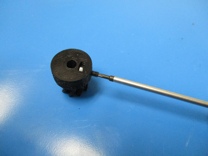
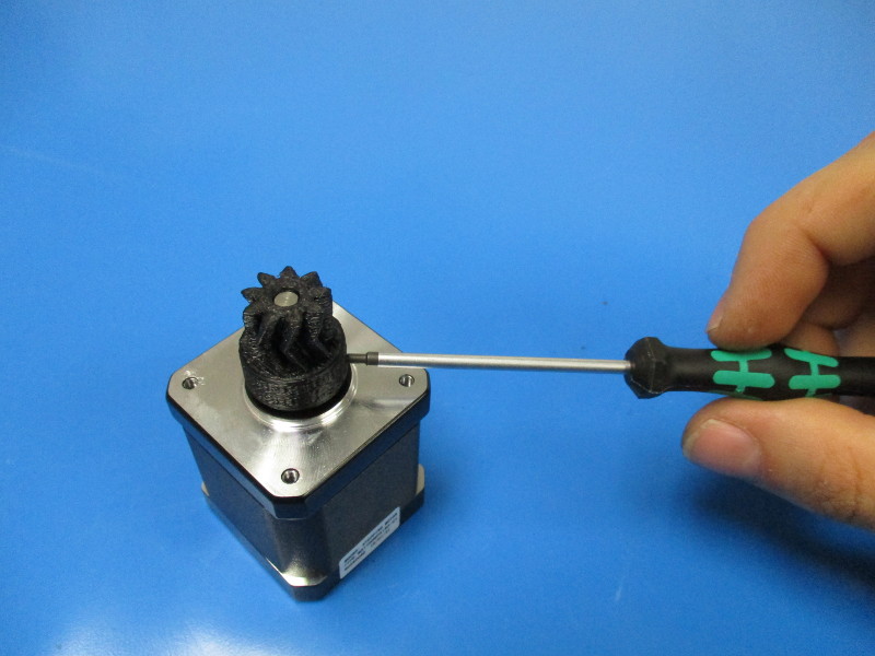
Install gear onto motor
Ensure that the set screw is aligned with the flat section of the shaft
Gather Parts:
Moons motor (EL-MT0029) assembled
Extruder body partial assembly
3x- M3x12 SHCS (HD-BT0039)
3x- black oxide washer (HD-WA0038)
Tools needed:
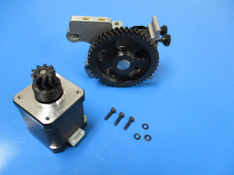
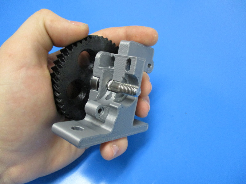
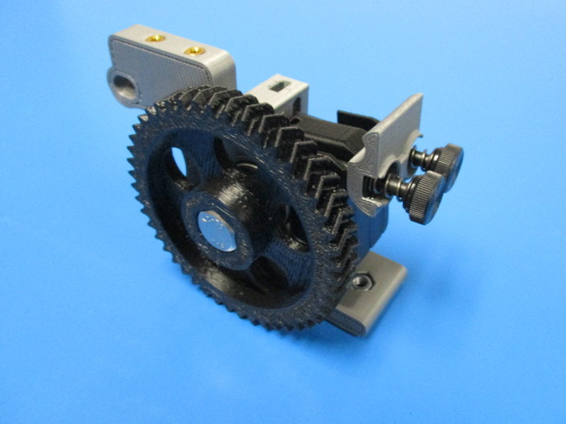
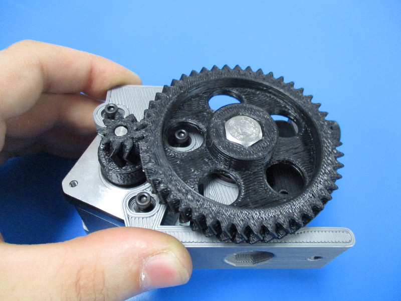
Mount the motor to the body (note the orientation of the motor and harness connection point)
Place the M3x12 SHCS with black oxide in the three holes that line up with the tapped holes in the motor
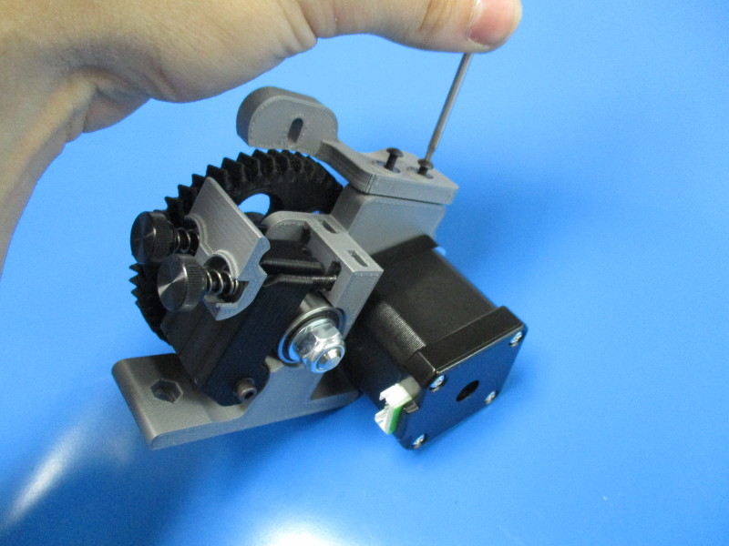
Note: the large gear and the small gear need to be mated together in a way that there is easy rotation but won't have any free movement known as “slap” between the gear teeth. To test for proper alignment of gears - tighten your screws down to 3 in/lbs, Hold the small gear firmly with your finger and thumb, and try to move the large gear back and forth to see if there is any small movement between the teeth of the gears. Rotate the large gear ¼ turn and repeat this process multiple times to ensure alignment. If there is movement the small gear and large gear need to be moved closer to each other. To do this you need loosen the M3 screws ¼ turn counter-clockwise and push the motor closer to the body. Repeat until you have desired the results, tighten screws once the fit is correct.) Torque to 3in*lbs

Gather parts:
Tools needed: 2mm driver
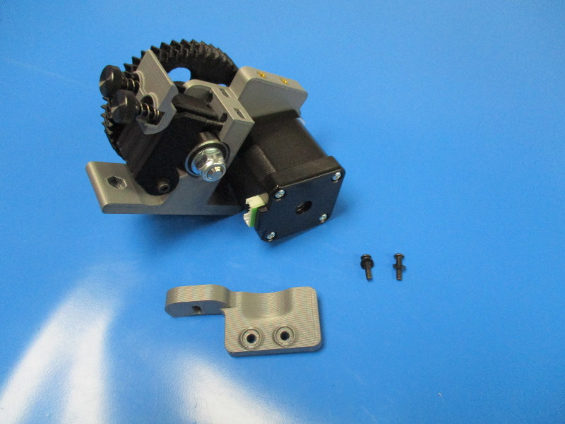
Install the extruder brace onto the body assembly using the two screws with washers
(note orientation of the brace on body)
Gather parts:
Extruder body assembled
Extruder mount (AS-TH0033)
2x- M4 black oxide washer (HD-WA0039)
Mount plate (PP-MP0156)
Hot end assembled
2x- M4x20 SHCS (HD-BT0010)
150mm Piece of 3mm thick T-Glase
Tools needed:

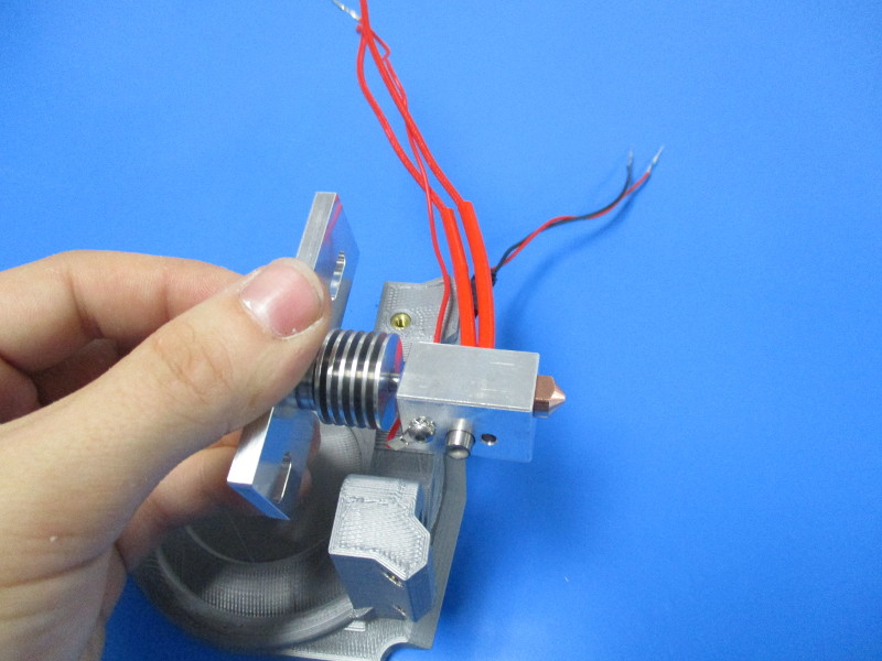
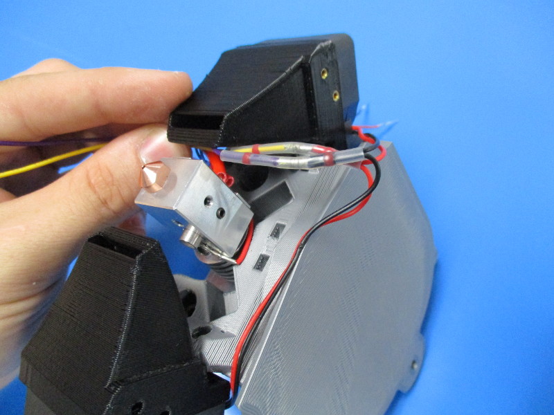
Insert the hot end into the slot of the mount plate (note orientation of the mount plate and hot end)
Install the Hot end onto the extruder mount using the M4x20 SHCS and M4 black oxide washers
Run filament through the body to help align the Hot end
Tighten the M4 screws to 8in*lbs
Ensure the heater block part of the Hot end is square with the mount plate
Pull filament out to insure the hot end is aligned


Gather parts:
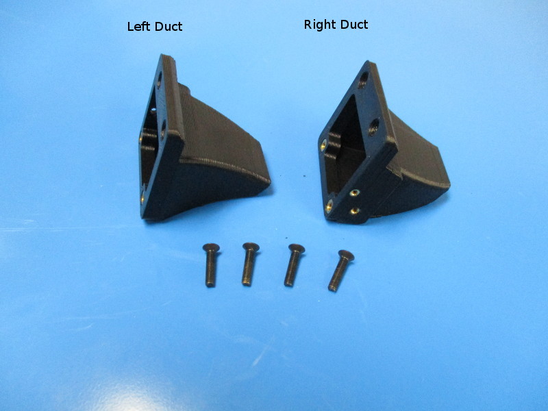
1x- Extruder fan duct left (AS-TH0017)
1x- Extruder fan duct right (AS-TH0018)
4x- M3x14 FHCS (HD-BT0118)
Tools needed:
2mm hex driver
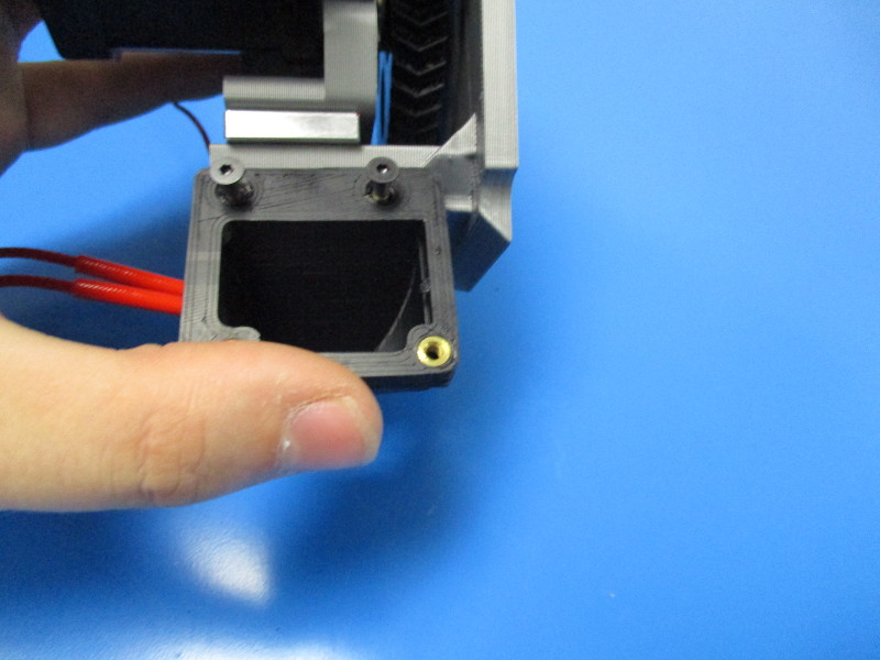
Align the right fan duct with the M3 brass inserts on the right hand side if the extruder mount
Secure the fan duct with 2x- M3x12 FHCS tightened on 3 in*lbs
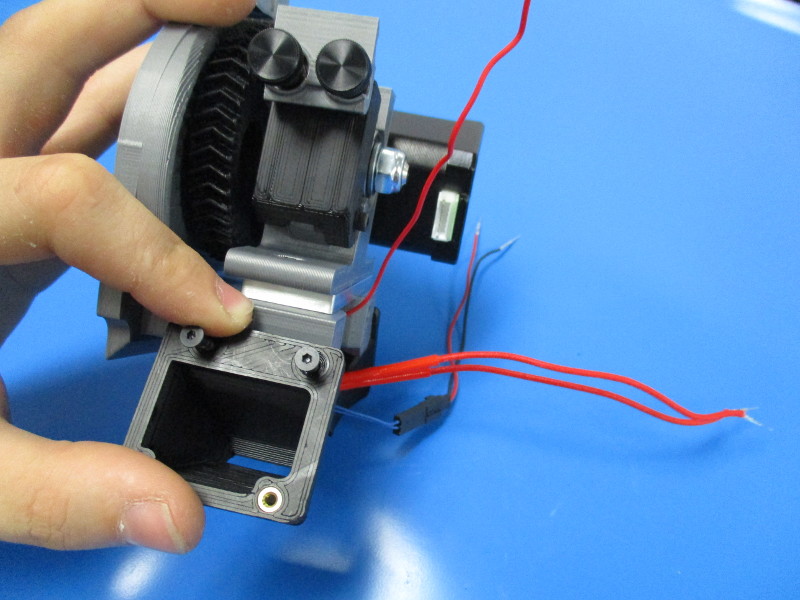
Repeat for the left side
Ensure that the harness from the Hot end are sticking out front of the extruder

Gather Parts:
1x- Extruder fan harness (AS-CB0012)
4x- M3x12 SHCS (HD-BT0039)
1x- cable tie (HD-MS0058)
Tools needed:
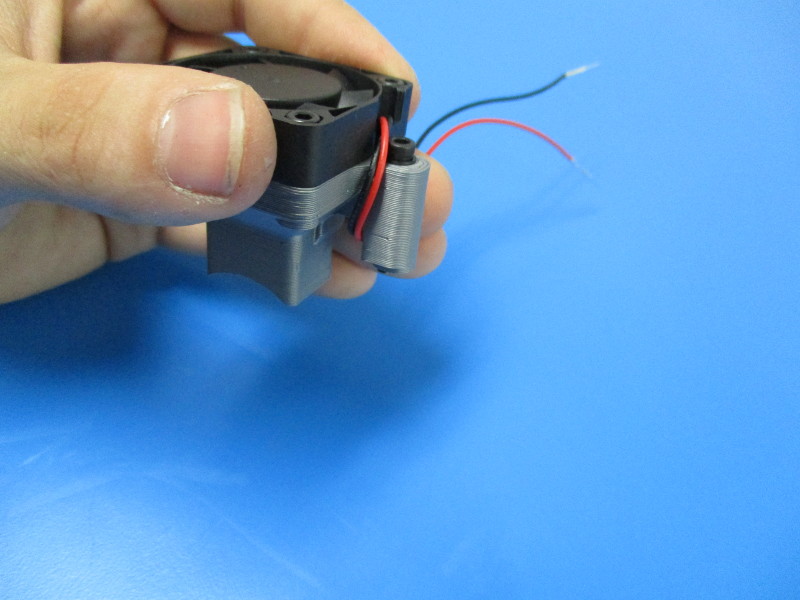
Attach the fan with the shorter wires to the right side of the extruder with 2x- M3x12 SHCS, note fan orientation and wire orientation
Tighten screws to 3 in*lbs
Attach the fan with the longer wires to the left side with 2x- M3x12 SHCS, , note fan orientation and wire orientation
Tighten screws to 3 in/lbs
Feed the yellow and purple wires through the opening between the right fan duct and the Hot end
Feed a cable tie through the slot as shown
Tighten the cable tie around the fan harness and clip-off excess cable tie


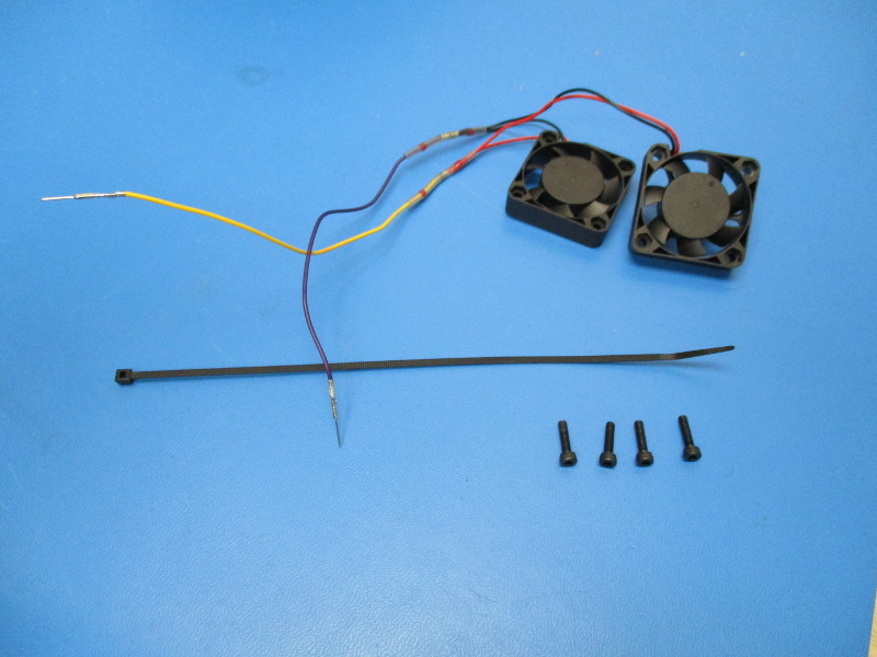
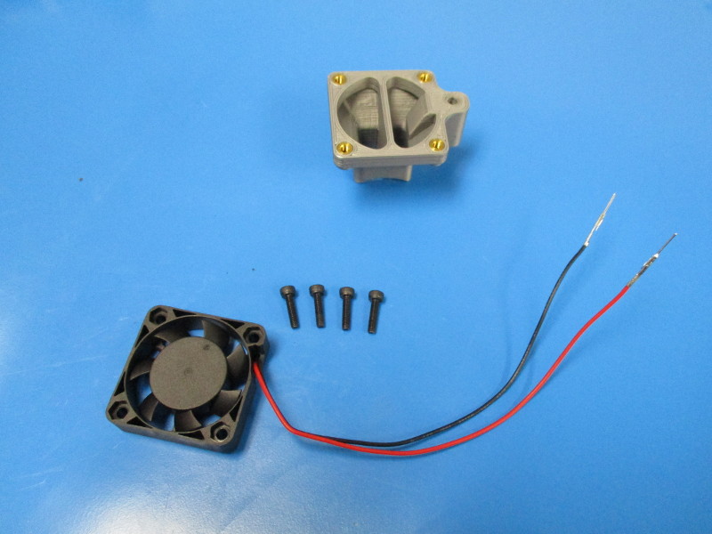
Gather parts:
1x- Heat sink fan duct (AS-TH0035)
4x- M3x12 SHCS (HD-BT0039)
4x- M3x25 SHCS (HD-BT0041)
4x- M3 black oxide washer (HD-WA0038)
1x- Pelonis 5V 40mm fan (AS-CB0011)
Tools needed:
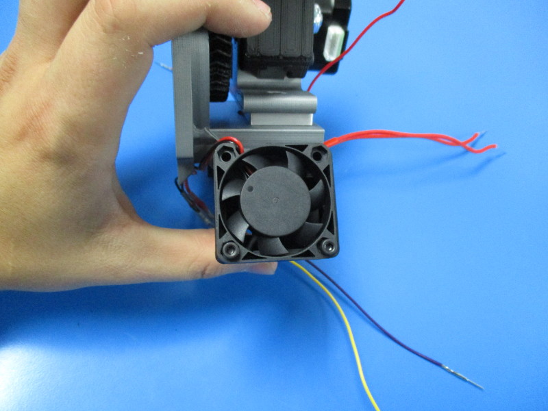
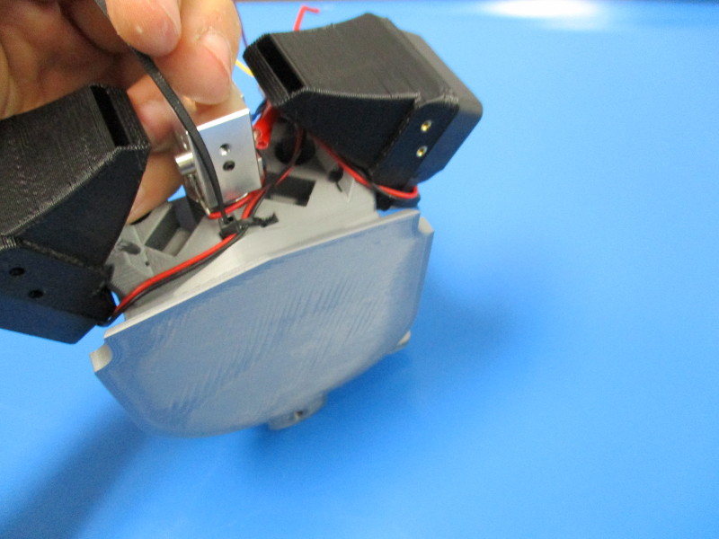
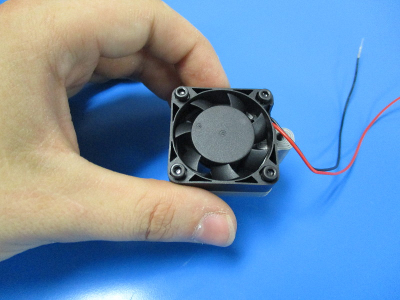
Attach the Pelonis 5V 40mm fan onto the heat sink fan mount using 4x- M3x12 SHCS (note orientation of fan and wires)
Tighten screws to 3 in*lbs
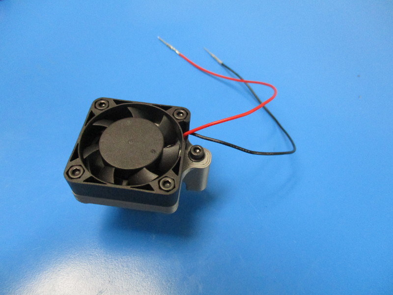
Install the M3x25 with M3 black oxide washer into the side hole
Wrap the harness coming from the fan over the M3x25 SHCS, around the front and under as shown
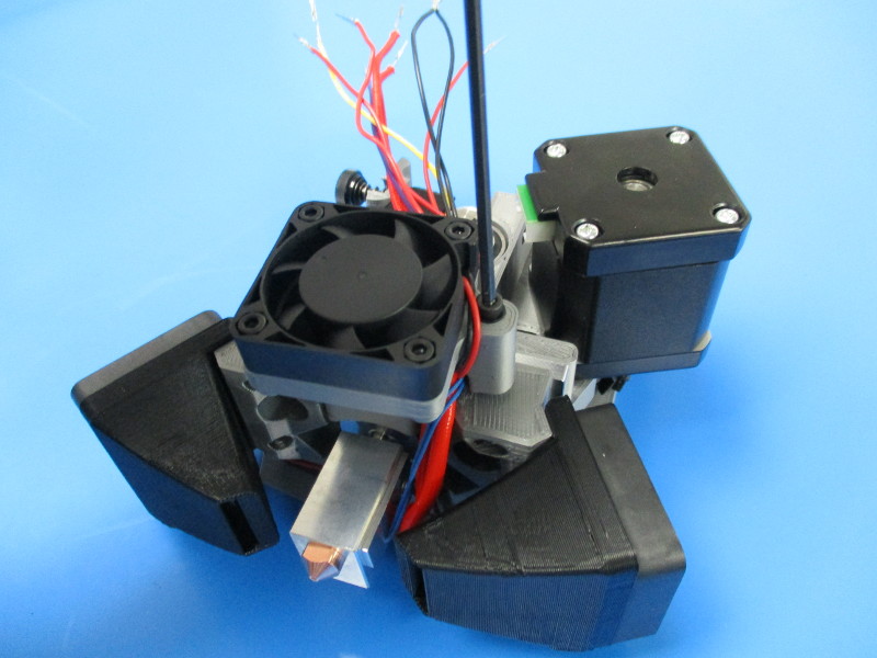
Install the assembled heat sink fan duct to the extruder mount
Ensure all harnesses are running through the opening that the 5V fan harness is running through
Tighten down the fan duct, being careful not to squish any wires, tighten screw to 3 in*lbs
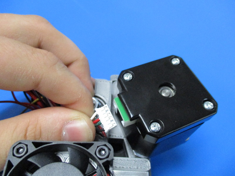
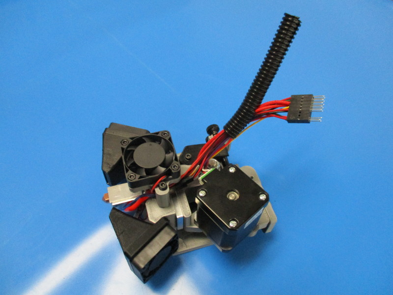
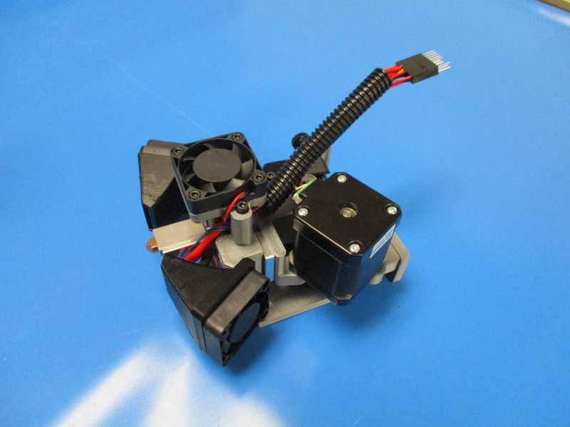
Plug in the extruder motor switch harness (EL-HR0096)
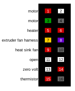
Pin all harnesses to their designated pin locations on the 16pin connector housing
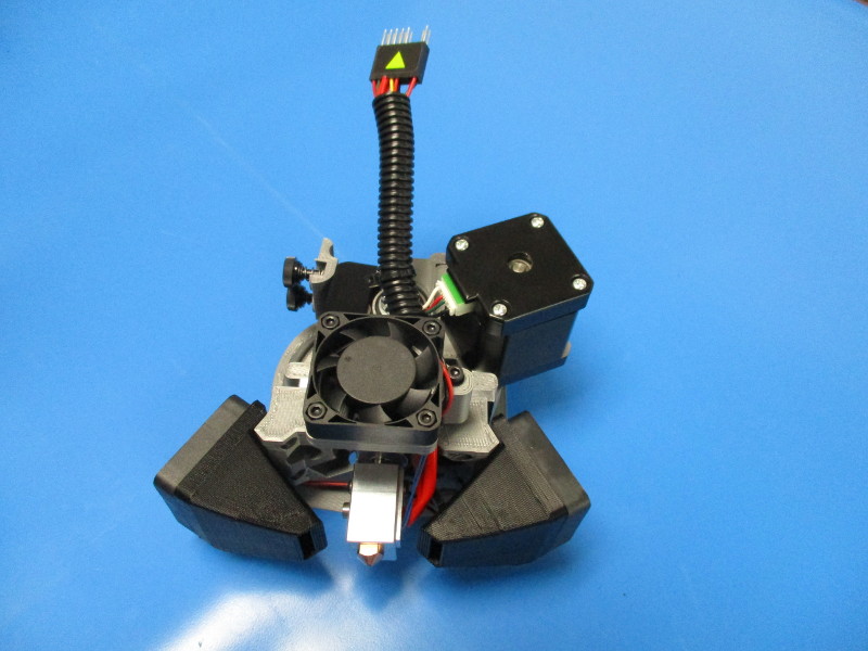
Gather parts:
100mmx 3/8" panduit (EL-MS0139
Cable tie (HD-MS0058)
Direction sticker (DC-LB0104)

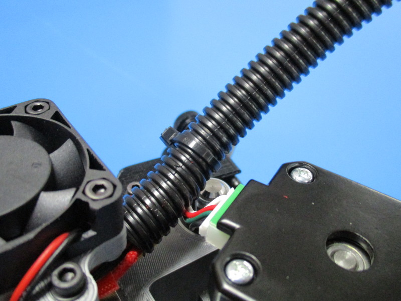
Slide 100mm x 3/8 Panduit over harnesses
Cable tie the Panduit shut over motor harness
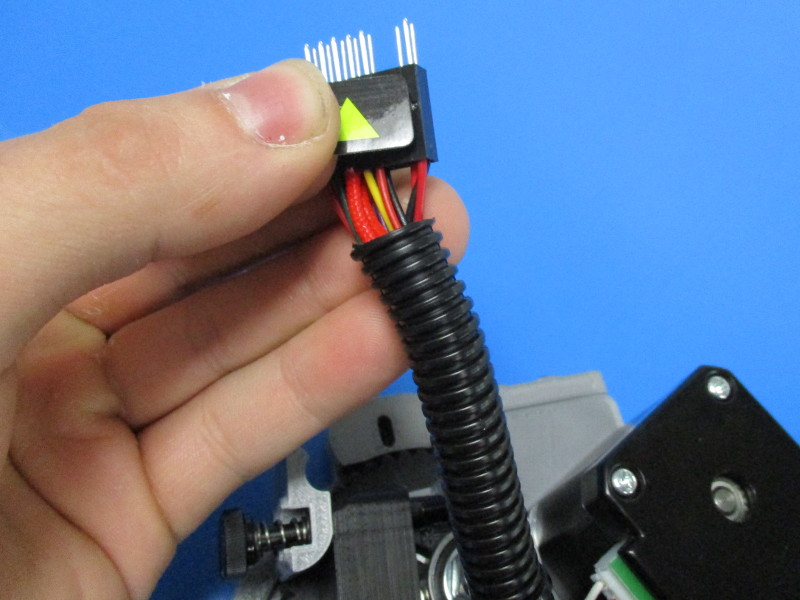
Apply arrow sticker on pin 1 side of connector
When the MOARstruder Assembly is complete, use the Tool Head Test Fixture to Calibrate the E-Steps.
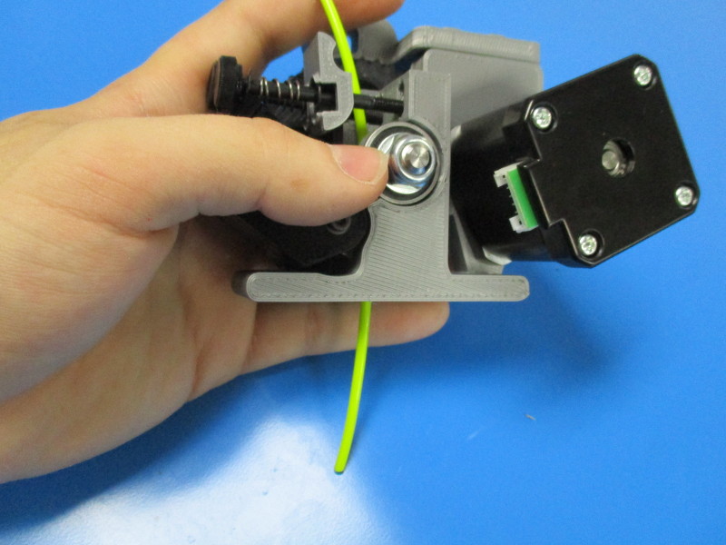
Install the MOARstruder into the test fixture as shown.
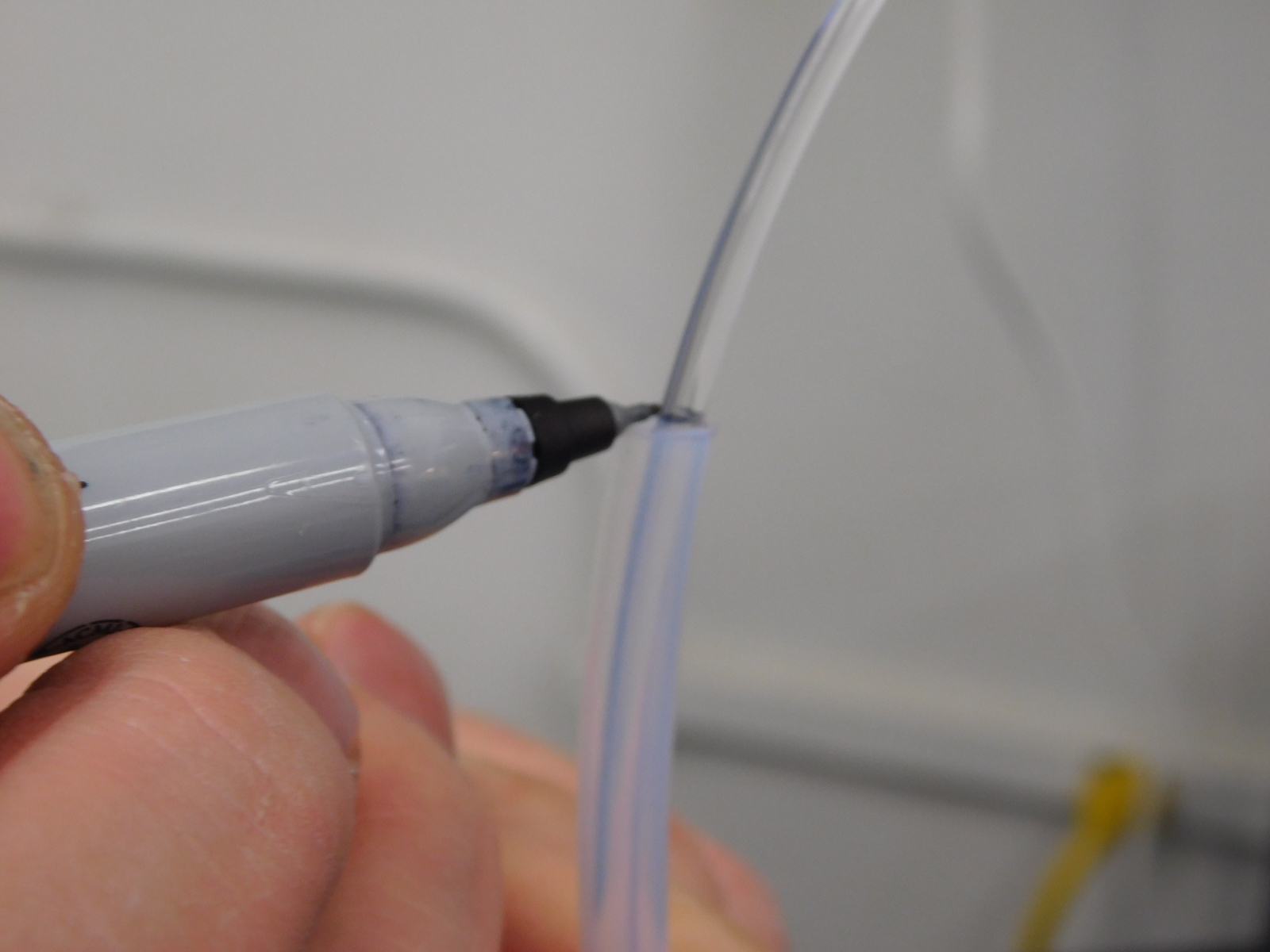
Insert test filament (T-Glase), use 300mm PTFE guide tube to measure 300mm from the top of the Idler Block and mark where the PTFE tube ends.
Turn on power.
Select 300mm spit test gcode as shown.
Note: Be aware that 300mm spit test also includes tests for 24v fans. 5v fan should be operational when power is applied to the Tool Head.
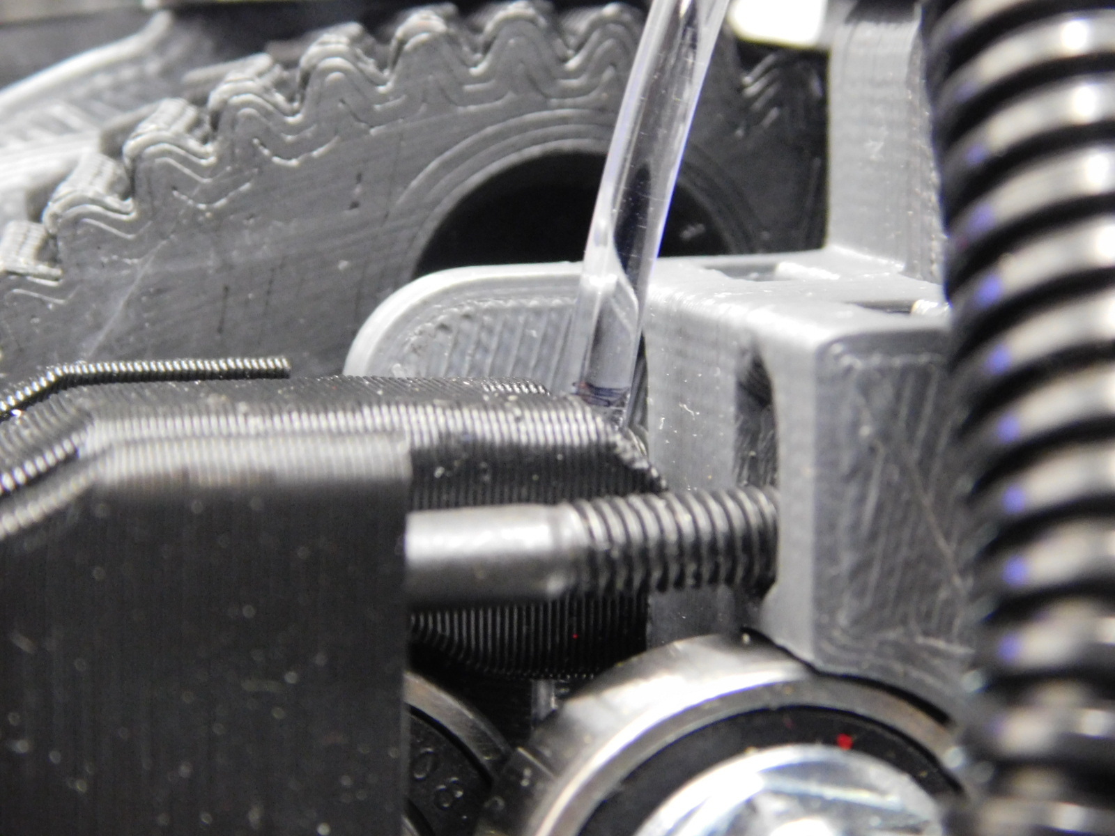
Ensure that exactly 300mm of filament was extruded when test is complete by verifying that the mark is flush with the top of the Idler Block as shown.
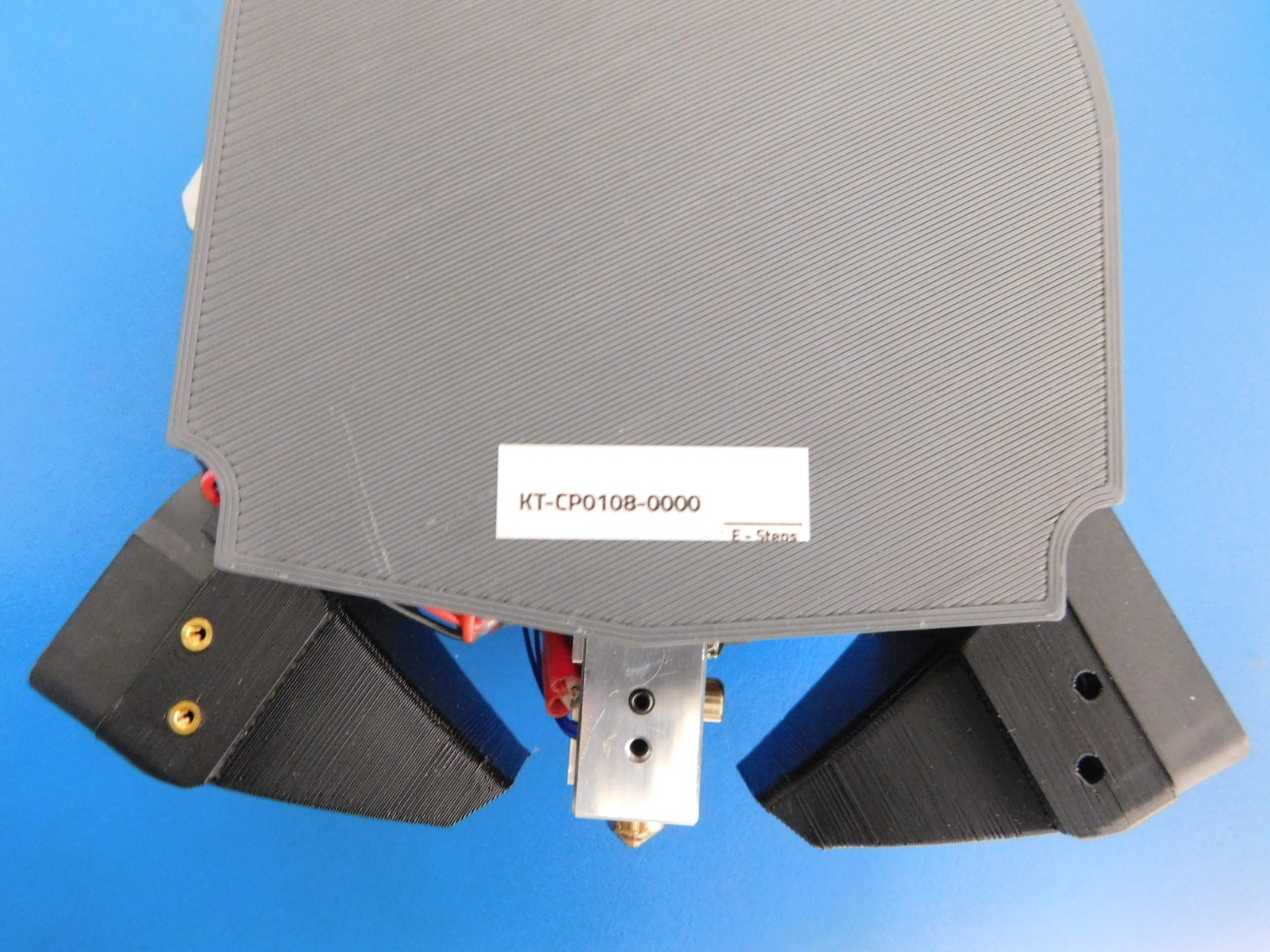
After E-Steps have been verified, remove MOARstruder from test fixture and place E-Step Calibration (with E-Step value) on the rear of the Tool Head.