Open HardwareAssembly Instructions
Guides for installation and assembly of the LulzBot line of products made by FAME 3D LLC.
Guides for installation and assembly of the LulzBot line of products made by FAME 3D LLC.
Components to build: KT-EL0072
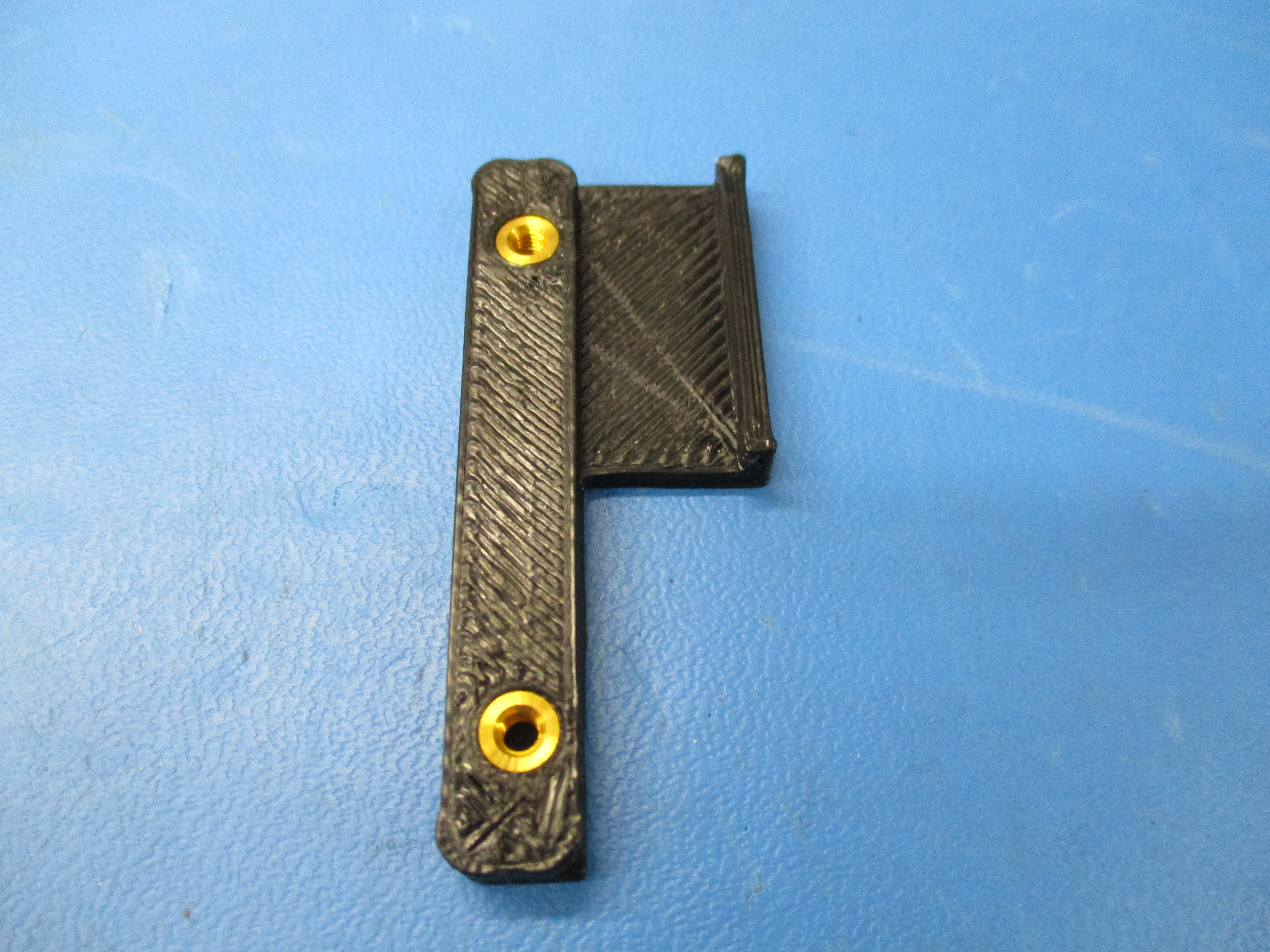
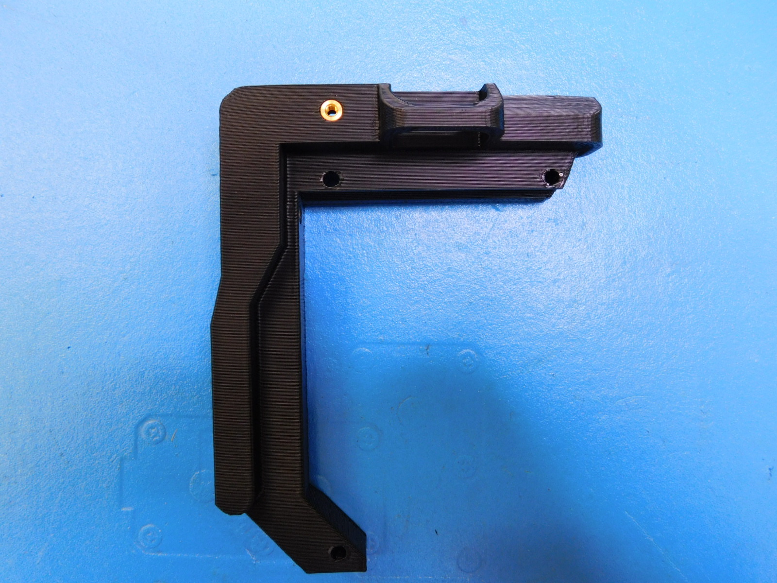
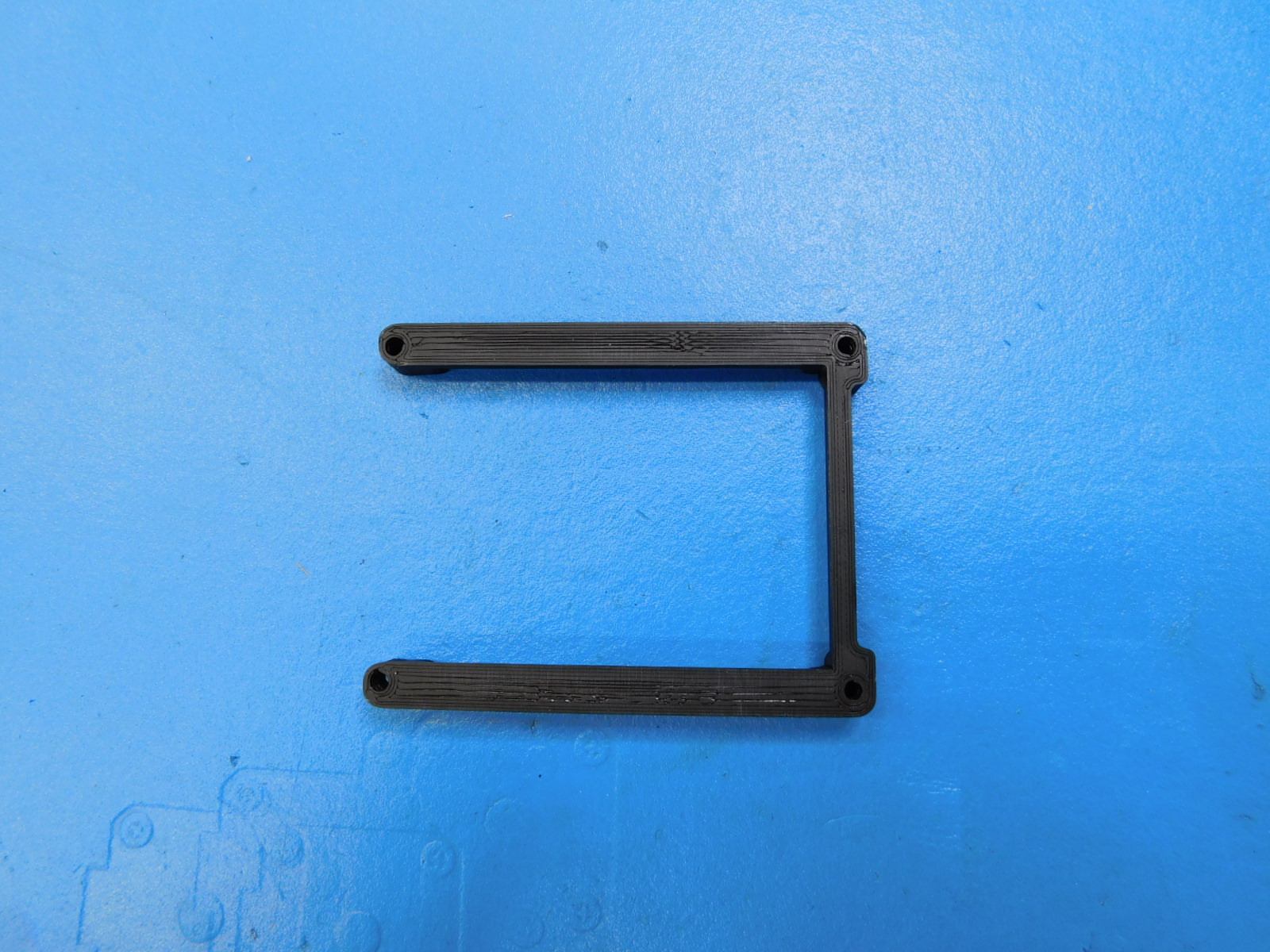
1x- [PP-IS0043] Mini LCD Bracket Right V1 with inserts
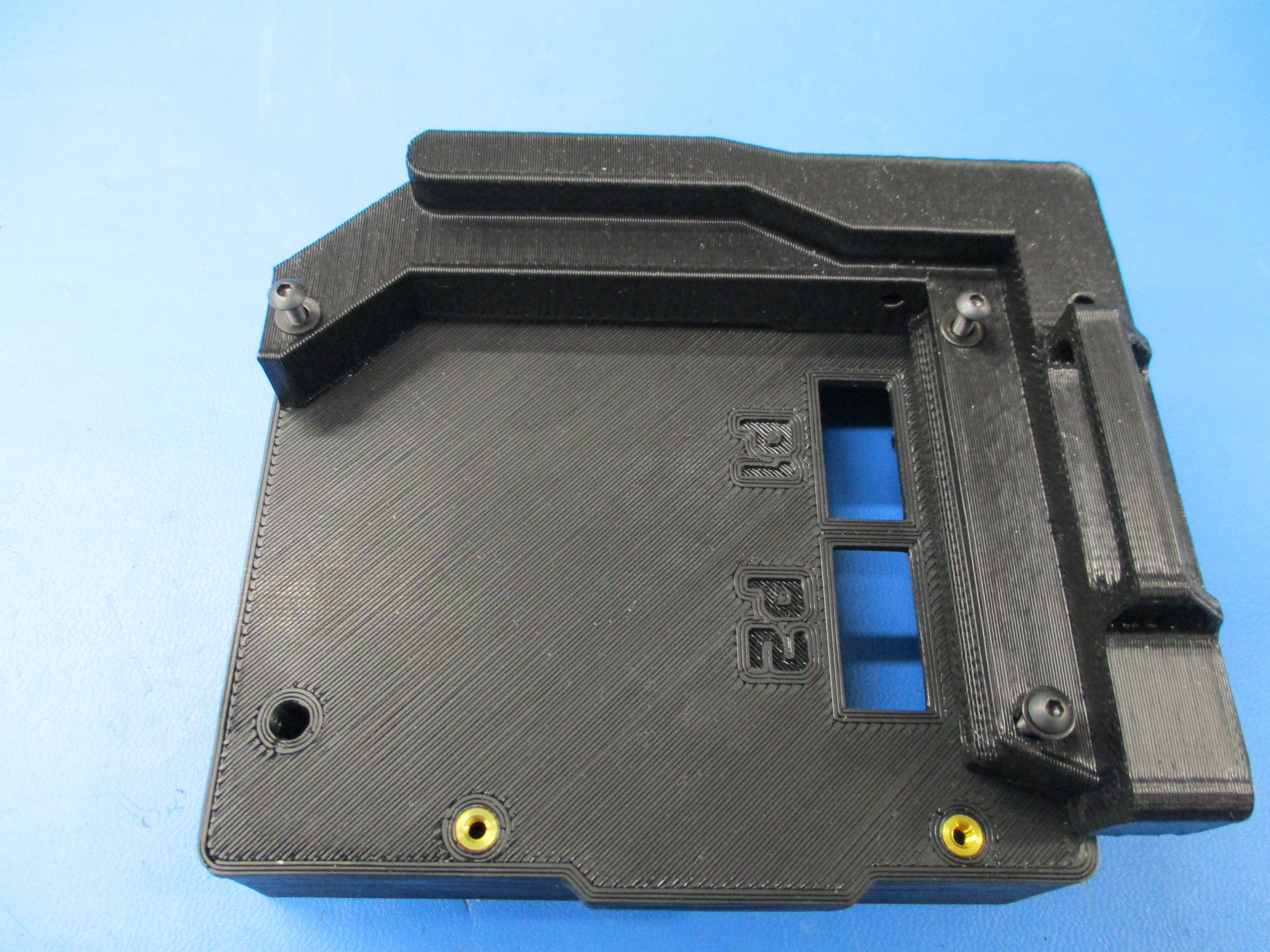
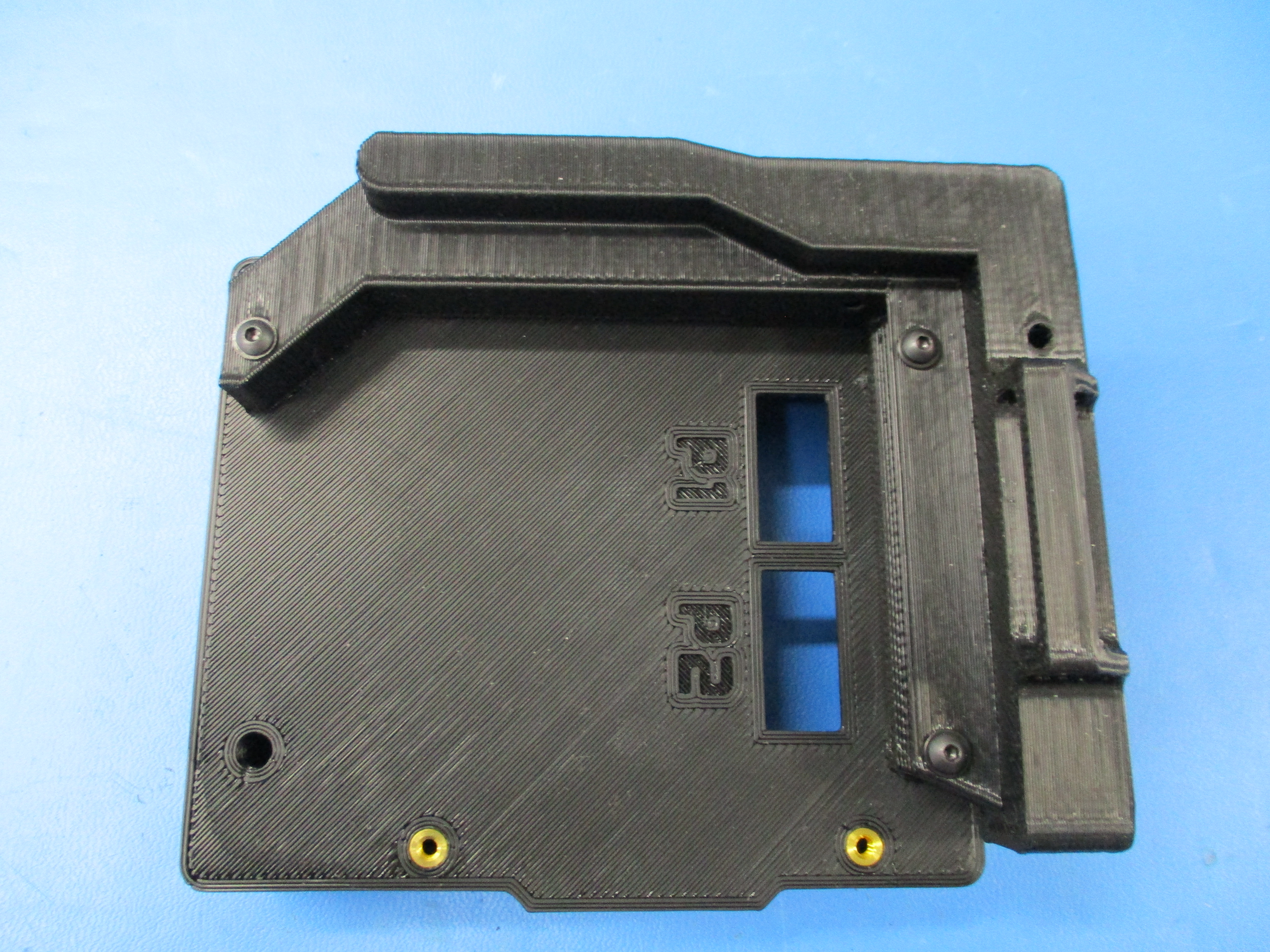
1x- [PP-IS0056] Mini LCD Case with inserts
4x- [PP-GP0089] LCD_spacer_v0.4
1x- [PP-GP0331] Mini LCD Knob
1x- [PP-GP0324] Mini LCD Bezel
1x- [PP-GP0328] Mini Accessory LCD Cover, Front
1x- [PP-GP0329] Mini LCD Bezel Spacer
5x- [HD-BT0137] M3 x 8 Bolt, BHCS, Black-Oxide
3x- [HD-BT0171] Black Oxide Steel Button-Head Socket Cap Screw M3 Size, 20 mm Length, .5 mm Pitch
4x- [HD-BT0206] M3 x 25 Bolt FHCS, Black-Oxide, Partially Threaded
8x- [HD-WA0038] Black-Oxide 18-8 Steel Flat Washer, M3 Screw Size, 3.2mm ID, 7.0mm OD
1x- [PC-BD0057] Full Graphic Smart LCD Controller, gLCD
1x- [PC-AS0041] Plastic Laser Cut LCD Cover
Components for boxing:
1x - SH-PA0049 - Korrvu Medium Retention Pack for Standard Tool Heads
1x - SH-BX0055 - TAZ 6 Tool Head and Accessory Box: 9-1/2 x 7 x 3-7/8 Die Cut, 32 ECT, B Flute, Kraft, Plain
1x - EL-HR0131 - LCD Harness 1 EL-HR0131 Cable Drawing
1x - EL-HR0132 - LCD Harness 2 EL-HR0132 Cable Drawing
1x - AS-EL0001 - Mini LCD add on assembly
1x - AS-PK0023 - Mini LCD Packaging assembly
1x - DC-LB0144 - Front label
1x - DC-LB0145 - Back label
14" - SH-PG0056 - Kraft packing tape
Components for AS-PK0023:
2x - PP-IS0054 - Top cable bracket
1x - PP-IS0055 - Side cable bracket
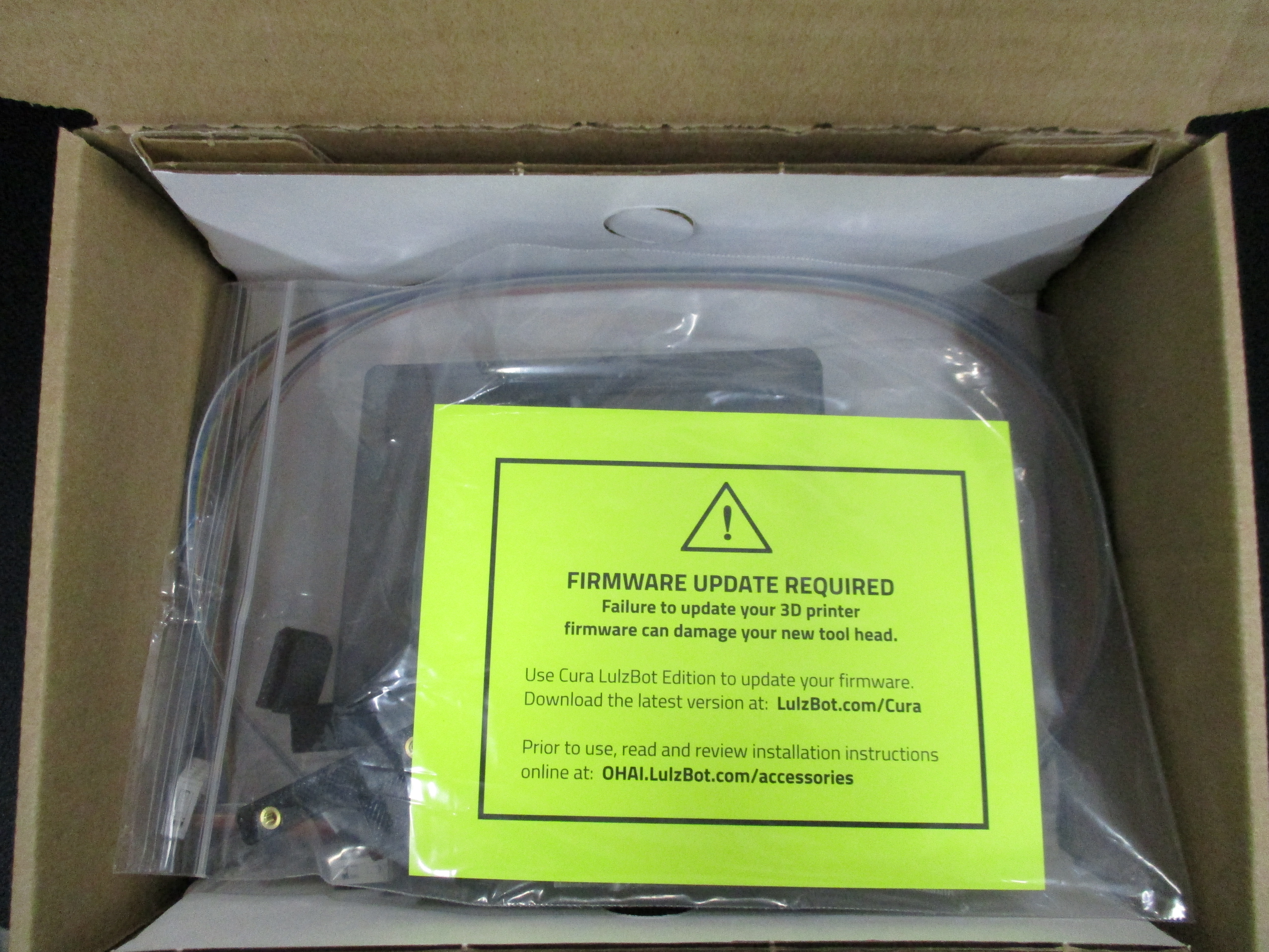
1x - DC-MS0054 - Firmware update card
1x - DC-LB0060 - Congratulations card
1x - El-MS0385 - SD card
4x - HD-BT0128 - M3x6 FHCS
2x - HD-BT0137 - M3x8 BHCS
2x - HD-BT0206 - M3x25 FHCS
2x - HD-WA0038 - M3 washer
1x - SH-PG0001 - 2x3 Bag
1x - SH-PG0006 - 6x9 bag
1x - SH-PG0031 - ESD bag
1x - DC-LB0174 - P65 Warning Label
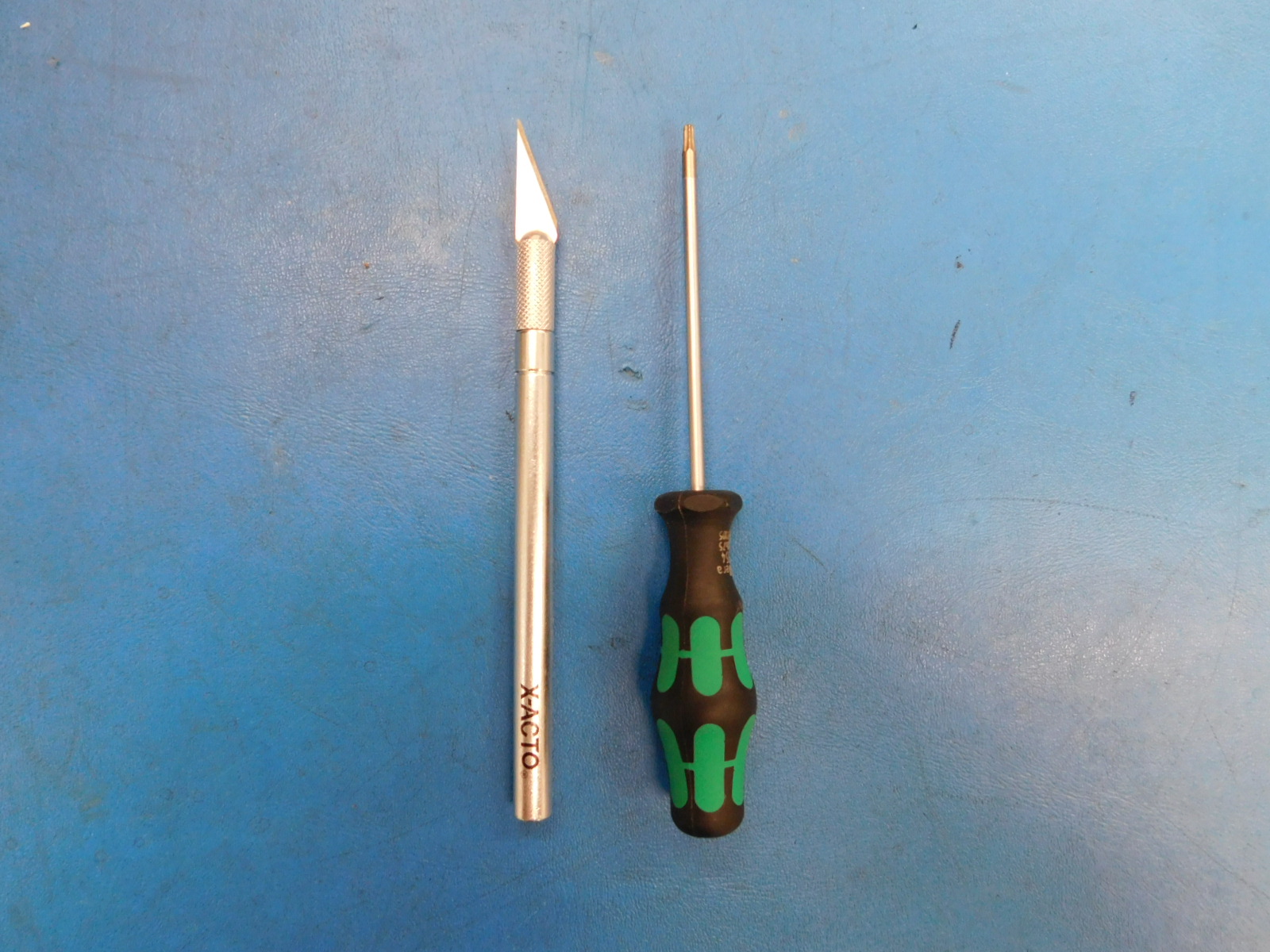
Tools for Assembly:
1x- M2 hex driver
1x- Exacto blade

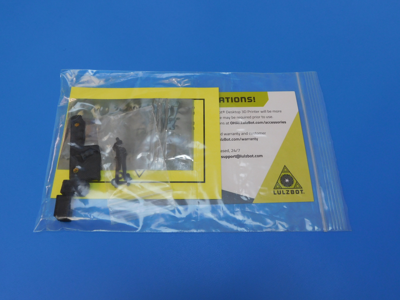
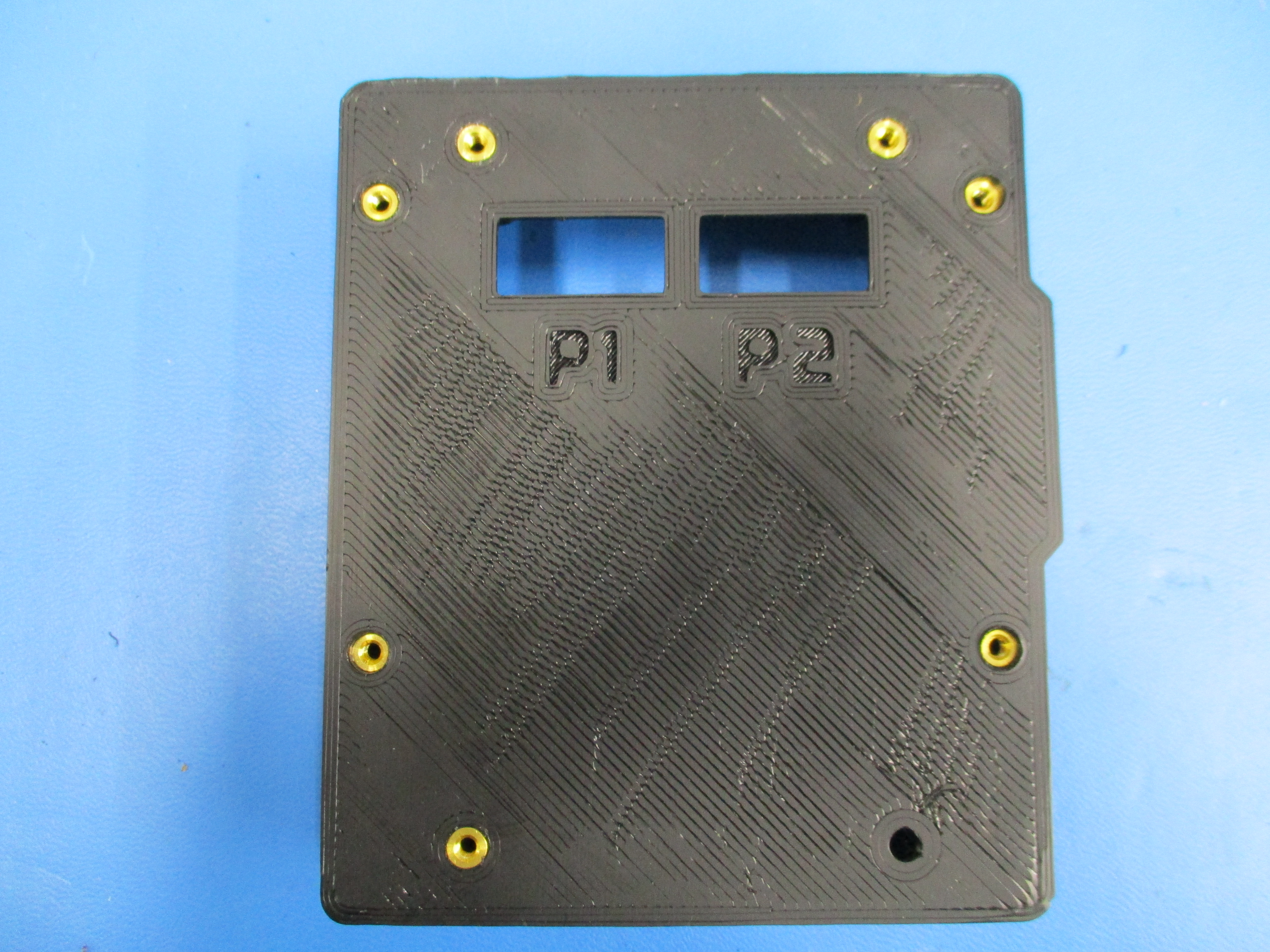
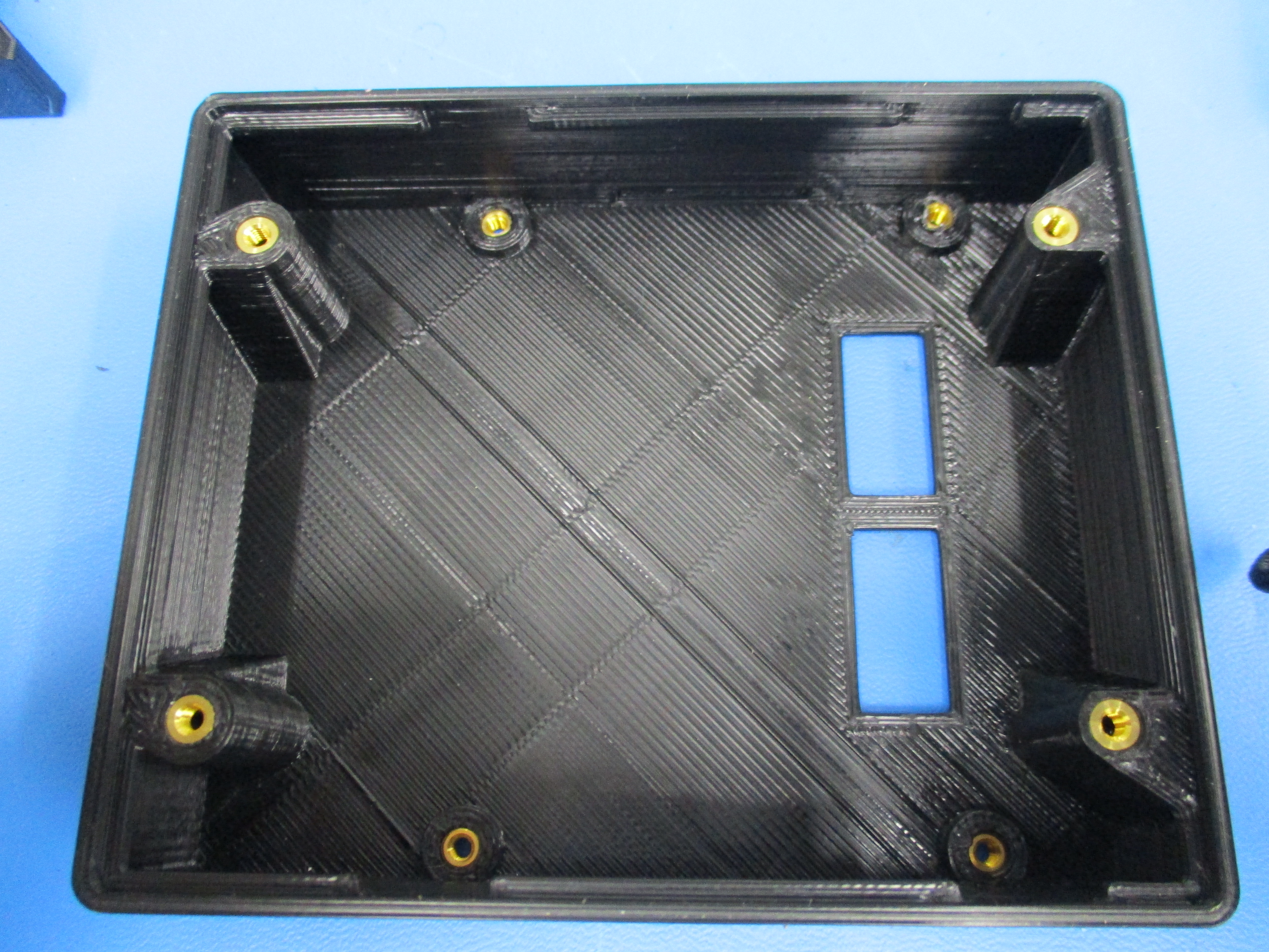
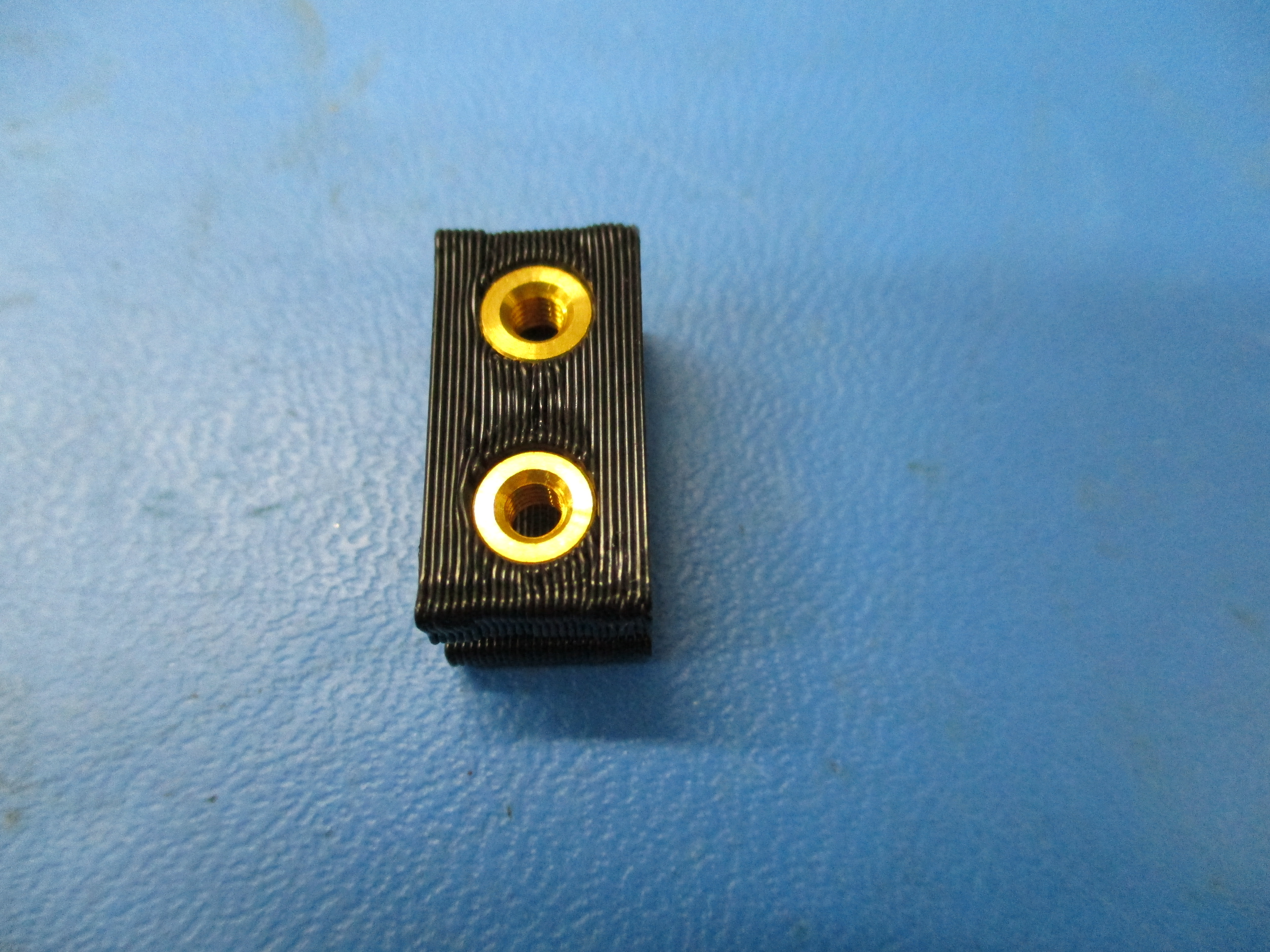
Install thermal inserts into printed parts, as shown.
7 on side A and 4 on side B

Install [PP-IS0043] Mini LCD Bracket Right V1 with inserts to PP-IS0056 - Mini LCD Case by placing the bracket on PP-IS0056 - Mini LCD Case.
Then install 3 [HD-BT0171] M3x20 bhcs through 3 [HD-WA0038] black oxide washers, then through the bracket, then PP-IS0056 - Mini LCD Case
Tighten all down.
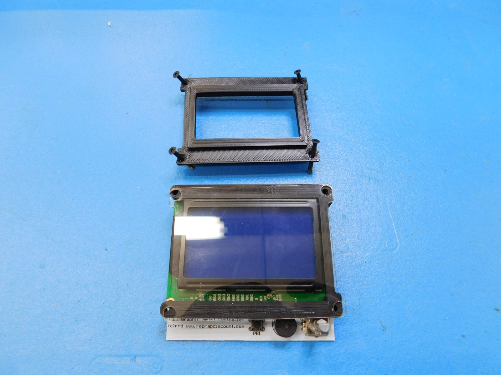
Install LCD spacers PP-GP0089 between the circuit board and lcd display.
Place PP-GP0329 - Mini LCD Bezel Spacer on top of LCD display
Place Screen protector PC-AS0041 on top of Bezel spacer
Insert 4ea. HD-BT0206 M3x25 FHCS through the Lcd bezel spacer - PP-GP0329 , PP-GP0230 - Bezel
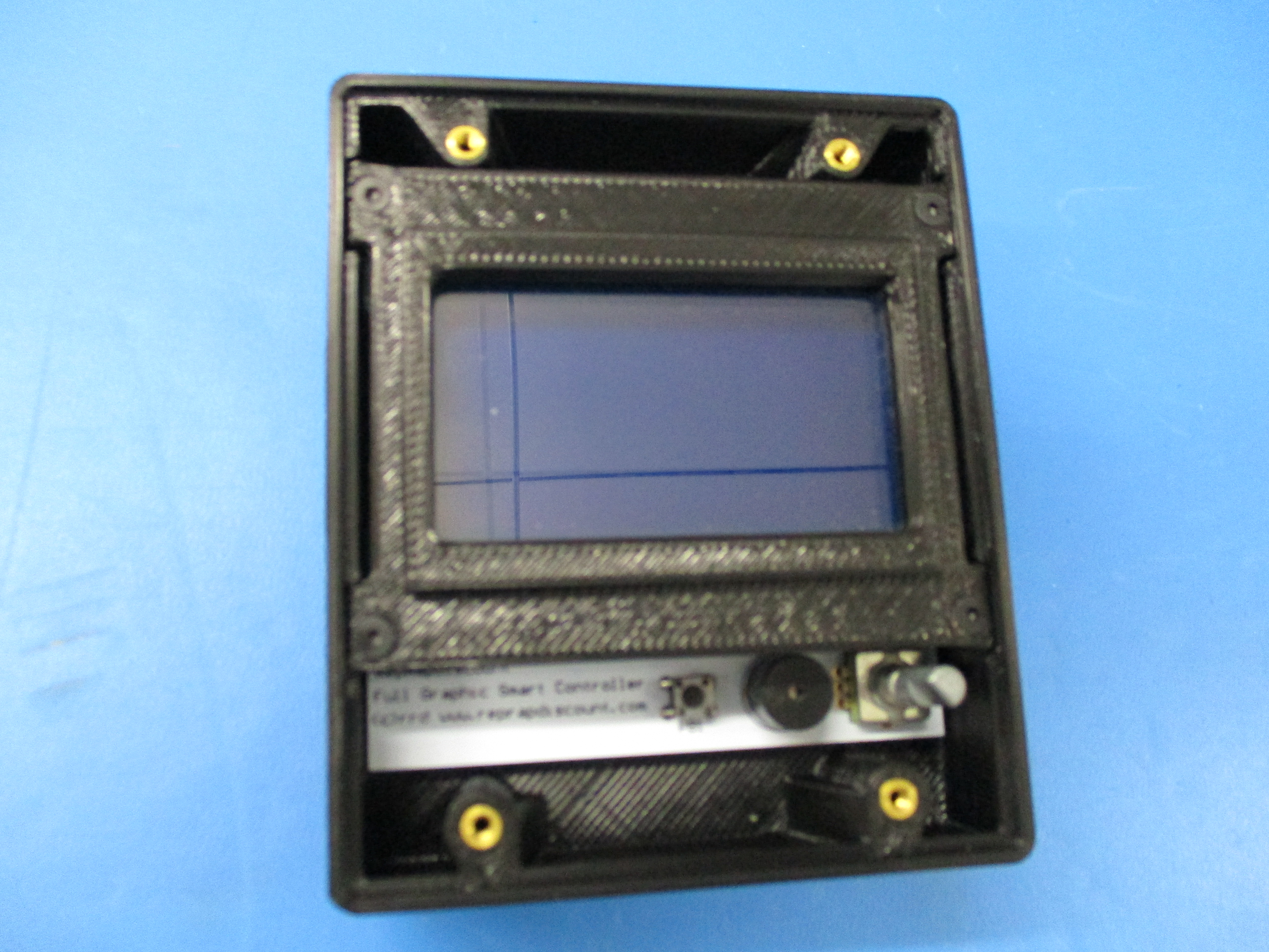
Set the LCD with screws down into the LCD case and tighten the screws down
Verify that the SD card will fit in the SD card slot once the LCD display has been installed in the case.

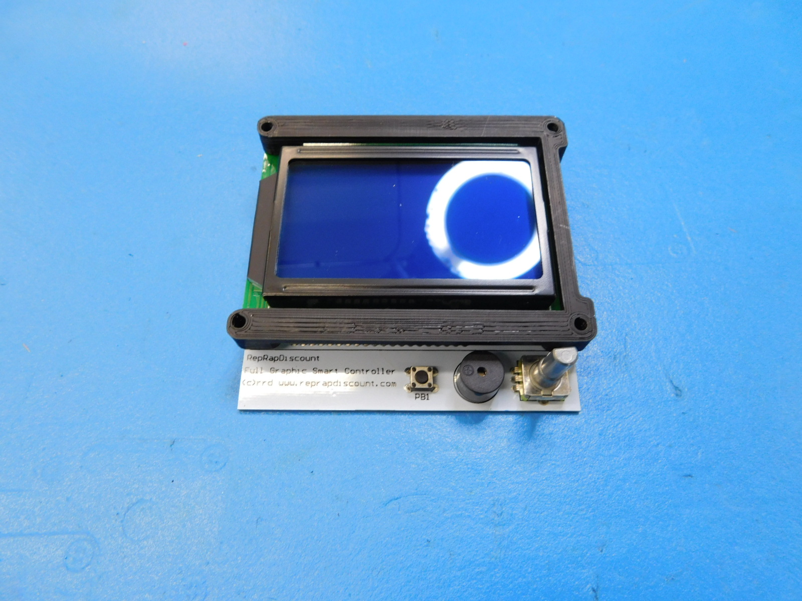
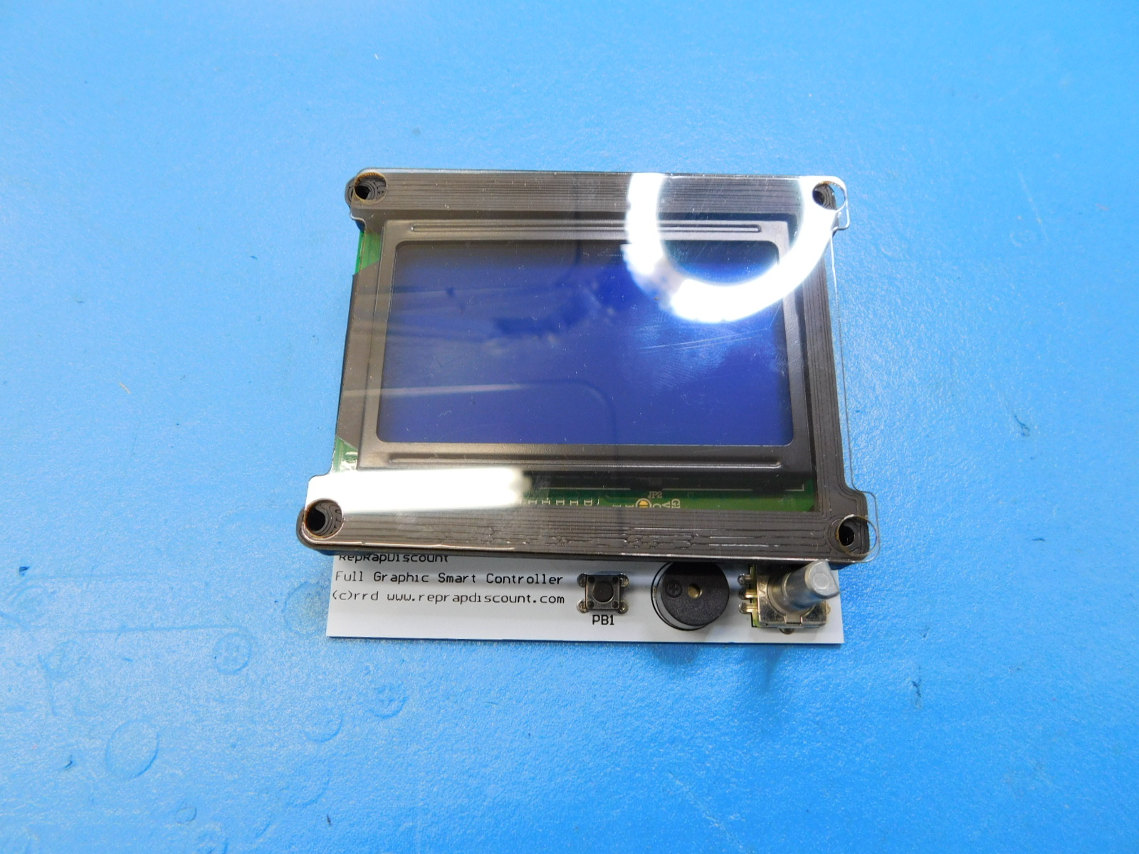
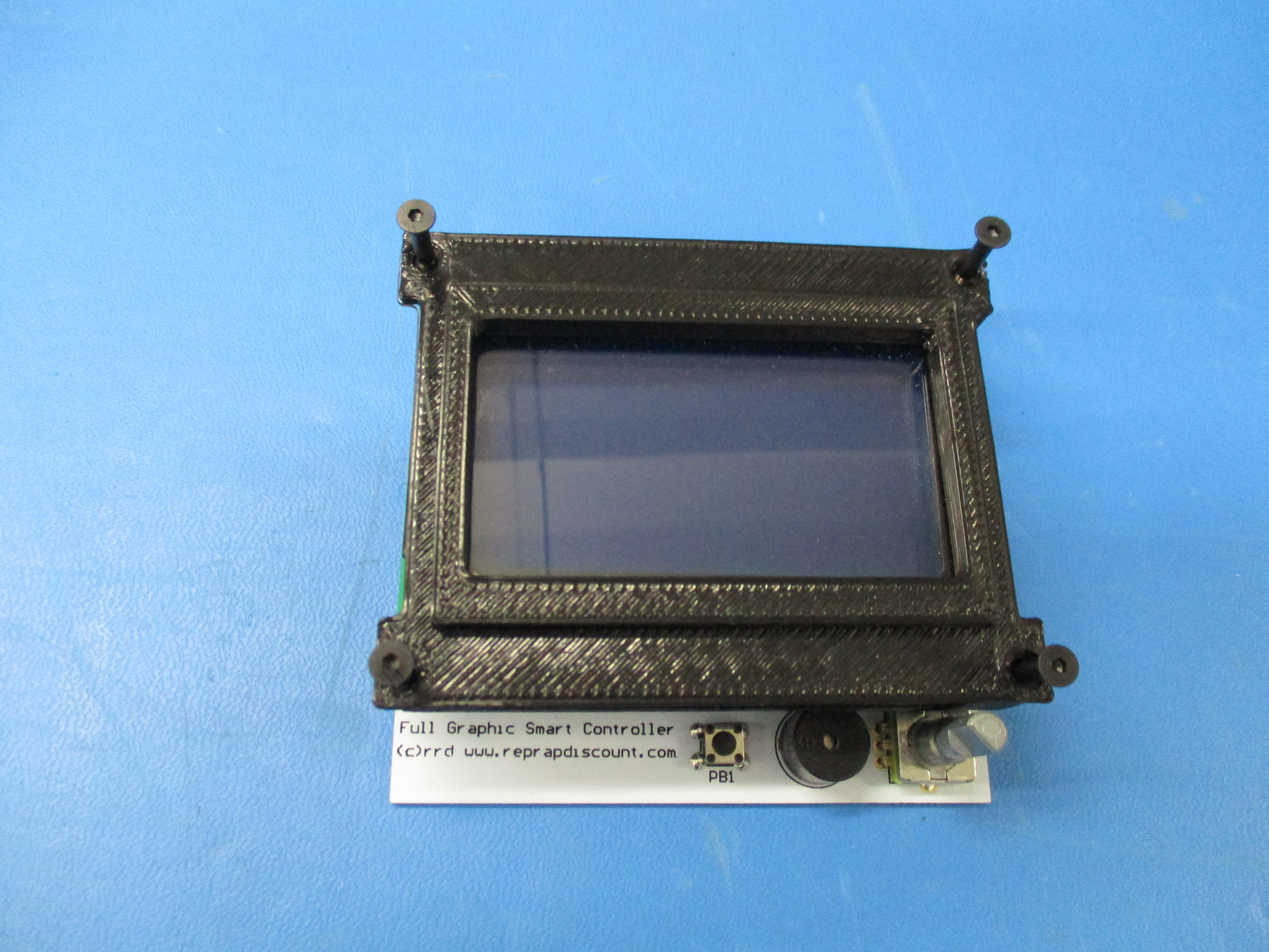

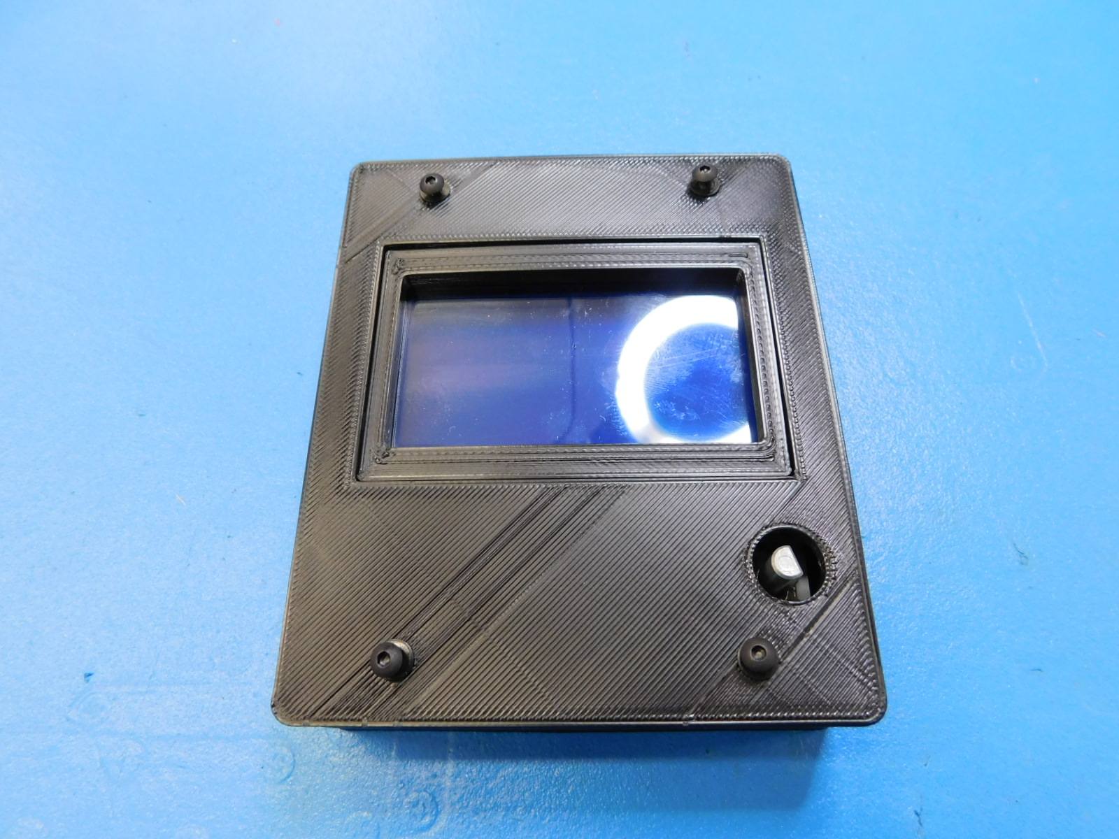
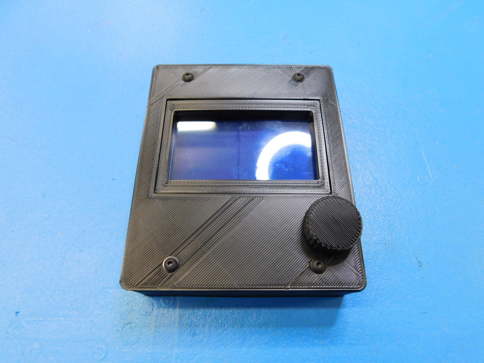
Place plastic laser cut lcd cover - on top of Bezel and place four M3x8 BHCS [HD-BT0137] (with washers [HD-WA0038]) through the cover. Then tighten down the screws. Then attach the LCD knob - PP-GP0331.
Insert a test SD card.
Plug the LCD into the test fixture.
Click the reset button on the RAMBo board.
Verify there are no defects in the LCD screen and it boots up normally.
Click the knob and verify it makes a beep.
Scroll through menu till you get to print from SD. Click and verify it lists files from SD card.
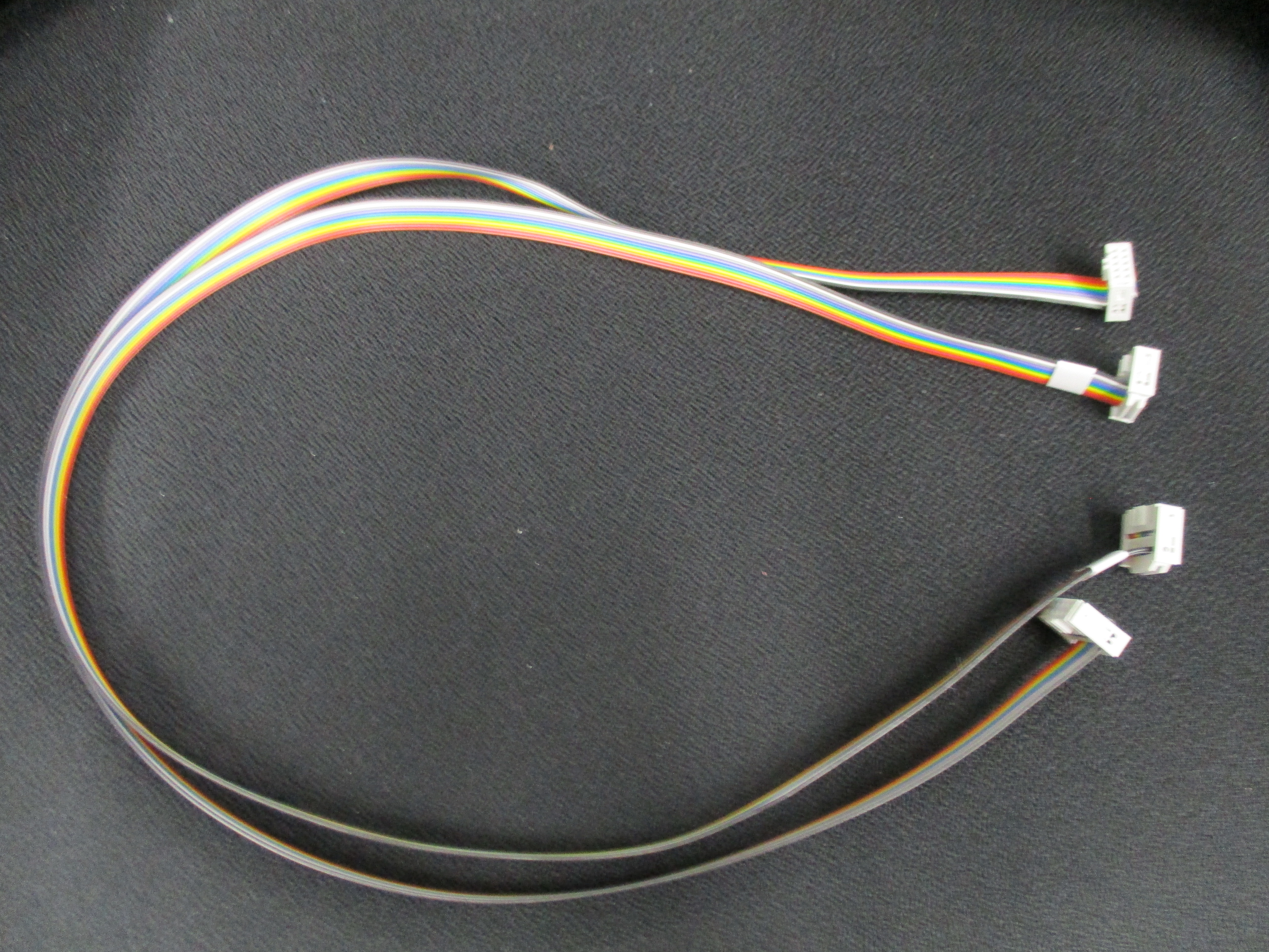
Harness 1: EL-HR0131, no label
Harness 2 EL-HR0132, requires label SH-PG0019 (White)
Install label: On harness 2 as shown on photo.
Verify that the cable length is a minimum of 690mm between the connectors.
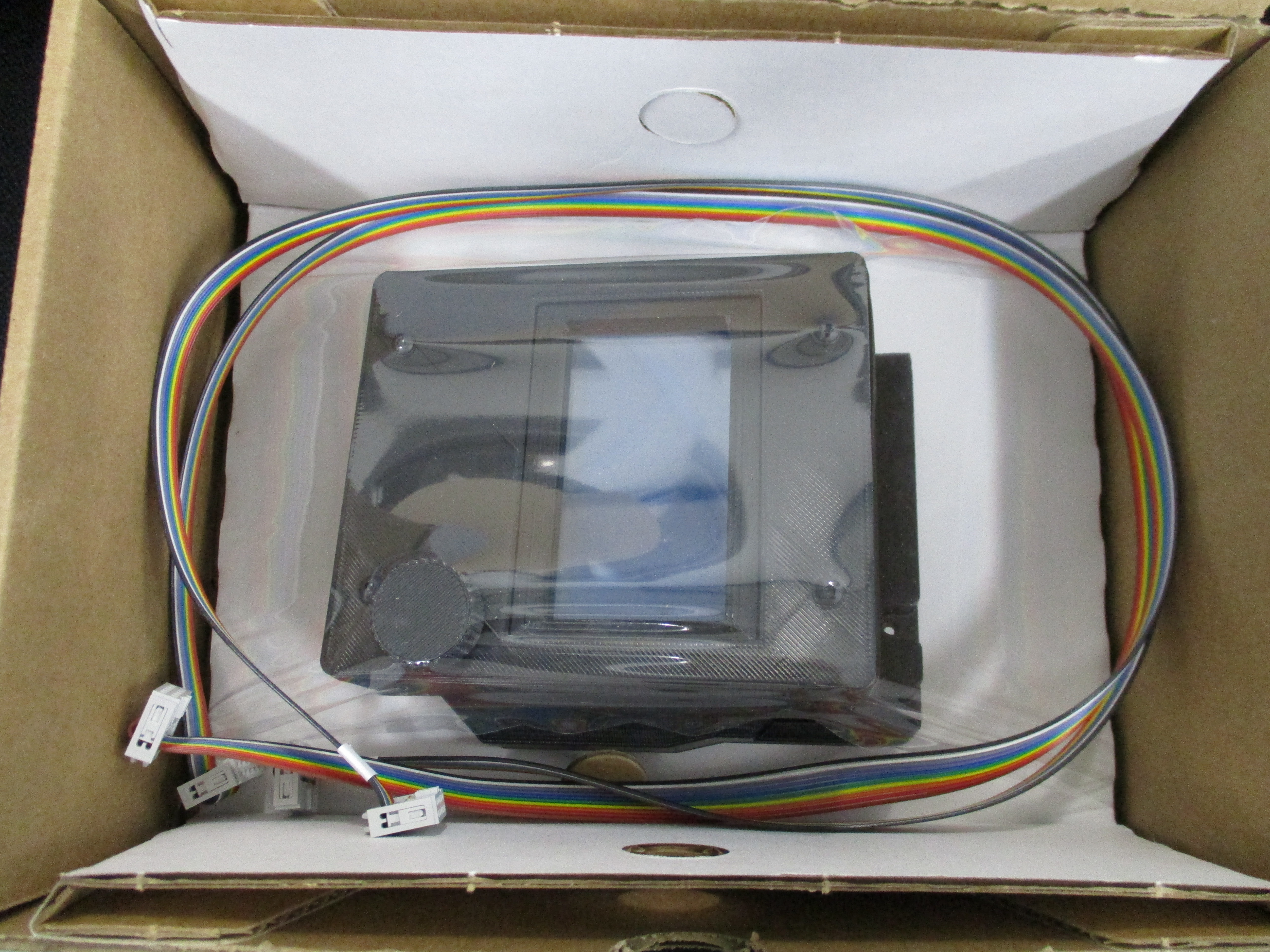
Place the LCD display in Korrvu-SH-PA0049, fold and set in box SH-BX0055
Place cables EL-HR0131 and EL-HR0132 into box.
Lastly, Place the [DC-LB0174] on the top-center of the box.