Open HardwareAssembly Instructions
Guides for installation and assembly of the LulzBot line of products made by FAME 3D LLC.
Guides for installation and assembly of the LulzBot line of products made by FAME 3D LLC.
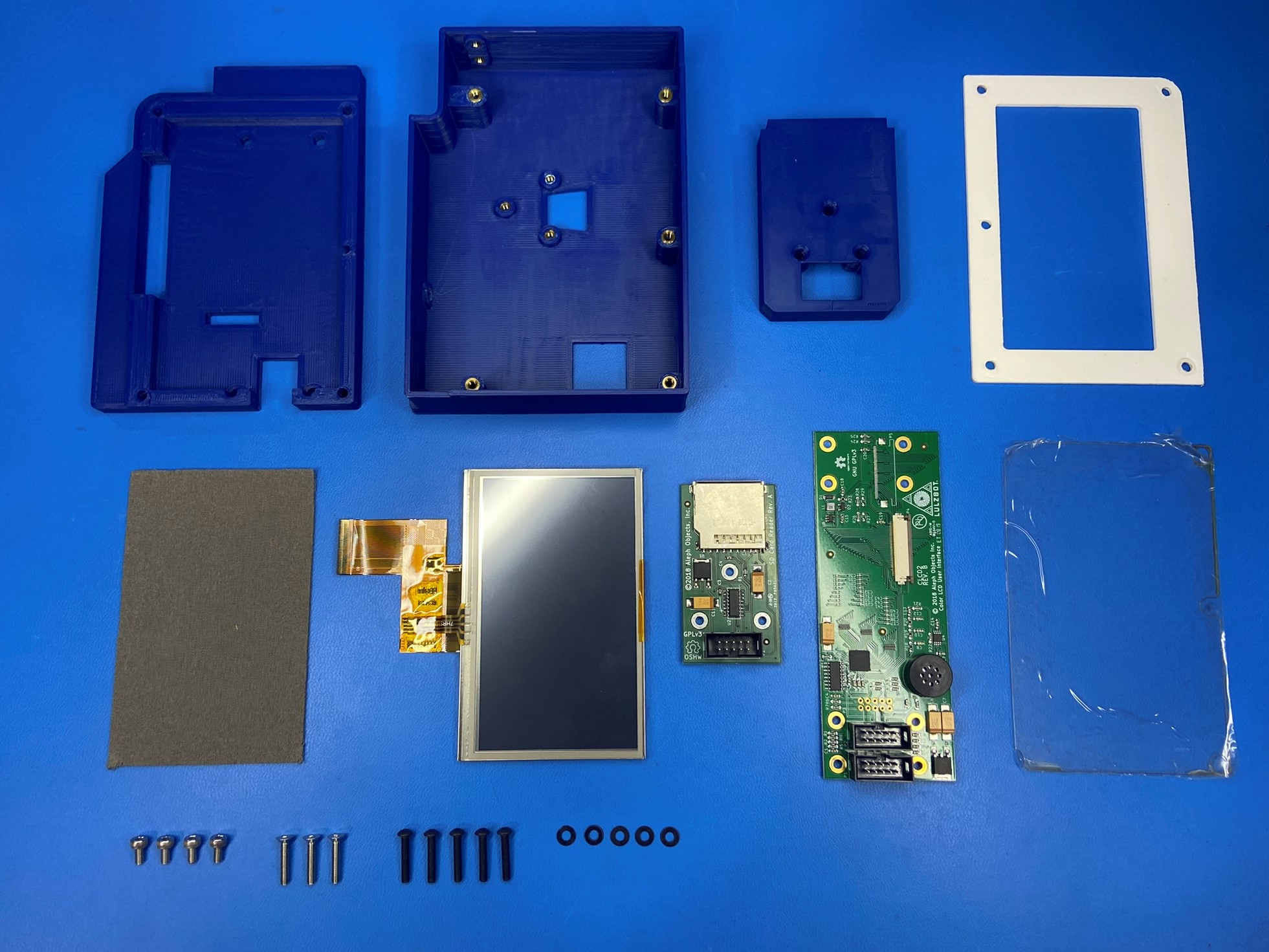
1x- [EL-MS0559] LCD 4.3" VTFT043GRNT01, w/ Resistive Touch Panel
3x- [HD-BT0082] M3x16 FHCS, SST
5x- [HD-BT0256] M3x16 BHCS, Black-Oxide
4x- [HD-BT0260] M3x6 SHCS, SST
5x- [HD-WA0038] M3 Washer
1x- [PC-BD0117] Color LCD Board, CLCD2 Rev B
1x- [PC-BD0124] Raw PCB SD Reader, Rev A1
1x- [PP-FP0174] Touch Screen Bezel Cover, White Polycarbonate, Bio
1x- [PP-FP0175] Touch Screen Pad, Bio
1x- [PP-FP0183] Plastic Laser Cut LCD Cover, Bio
1x- [PP-GP0458] LCD Case, Bio
1x- [PP-GP0460] LCD Center, Bio
1x- [PP-GP0472] SD Mount, Bio
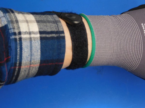
Before starting connect the grounding wristband that is connected to the table, make sure the metal part of the wristband is making contact with your skin.
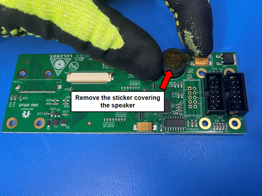
Take the color LCD board [PC-BD0117] and find the speaker by the LCD ports. Now remove the sticker that covers the holes on the speaker.
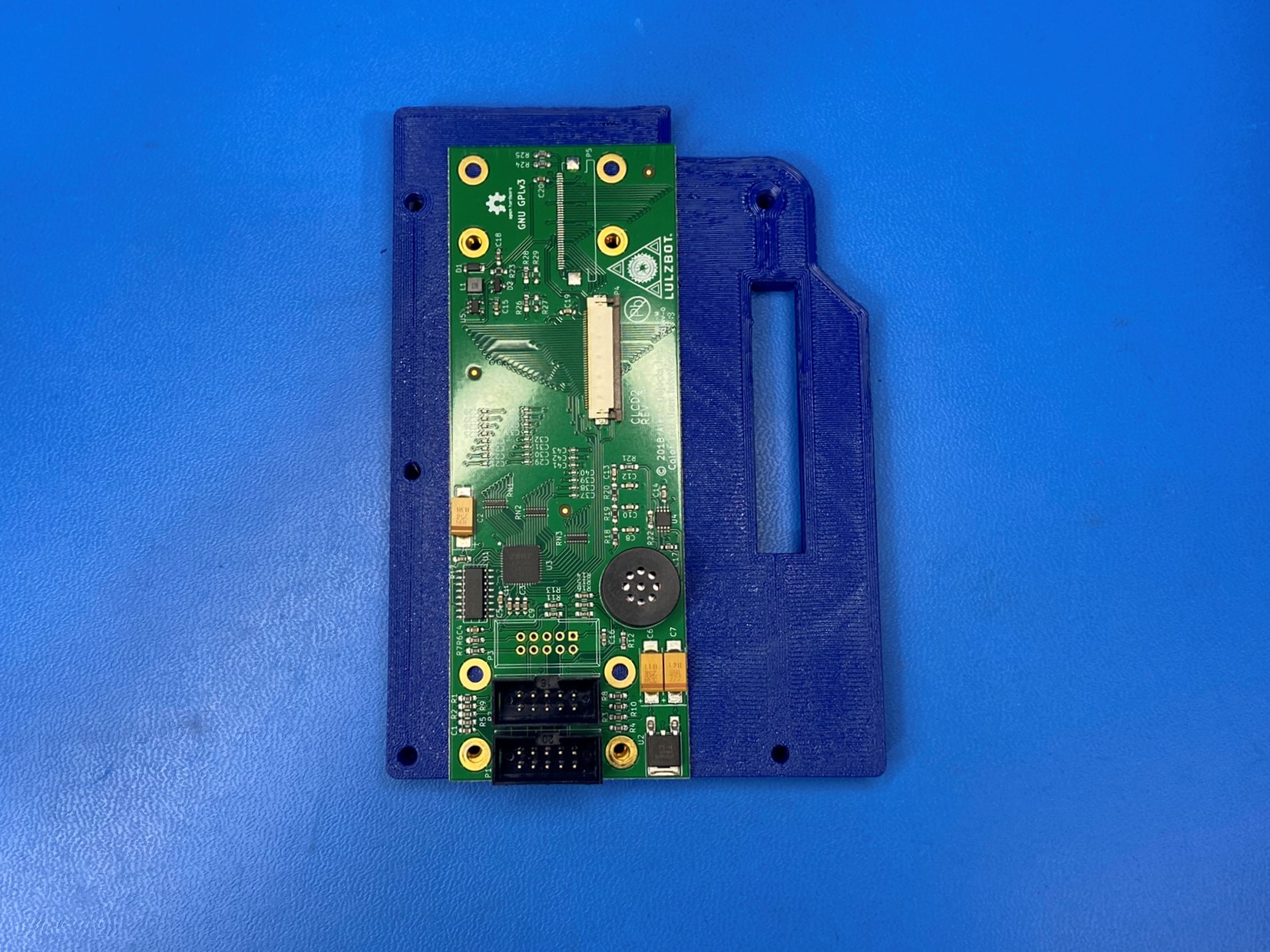
Then place the LCD center [PP-GP0460] on the table with the backside facing up. Then place the color LCD board over the LCD center as shown.
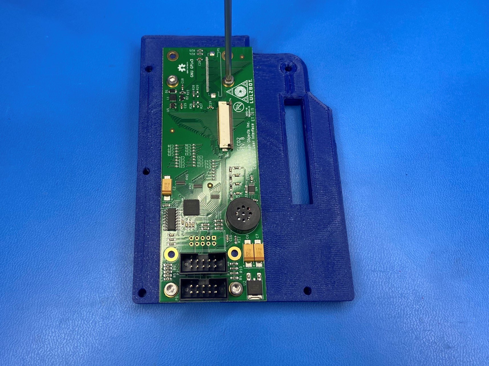
Use 4x M3x6 SHCS [HD-BT0260] to secure the LCD board to the LCD center.
DO NOT OVERTIGHTEN
Flip the LCD center over so that the front side is facing up. Then place the touch screen pad [PP-FP0175] inside the rectangular slot in the LCD center.
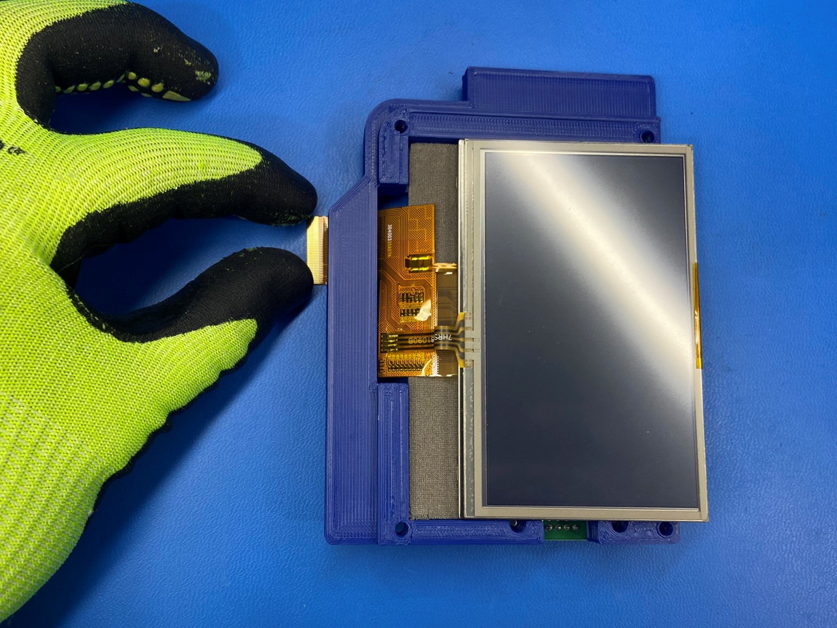
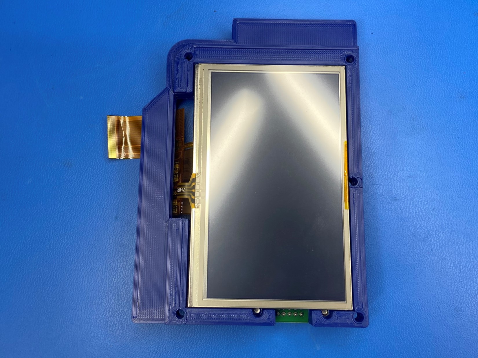
Now take the LCD 4.3" w/ resistive touch panel [EL-MS0559] and slide the ribbon cable through the slot on the side of the LCD center. Once the ribbon cable is fully through the slot, set the LCD touch panel inside the LCD center.
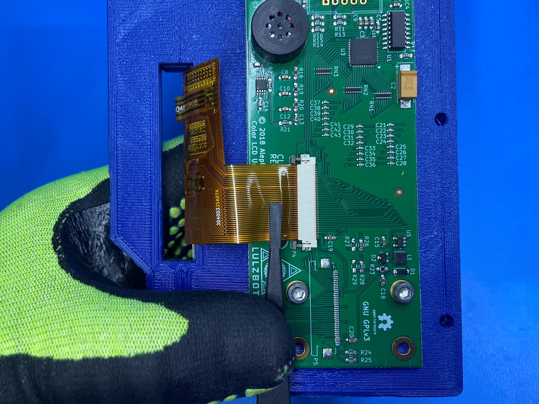
Carefully hold the assembly together and flip it over. Using a plastic tweezer connect the ribbon cable to the LCD board. Make sure the ribbon cable is pushed all the way in and then using the tweezer push the locks down and are on the side of the connector.


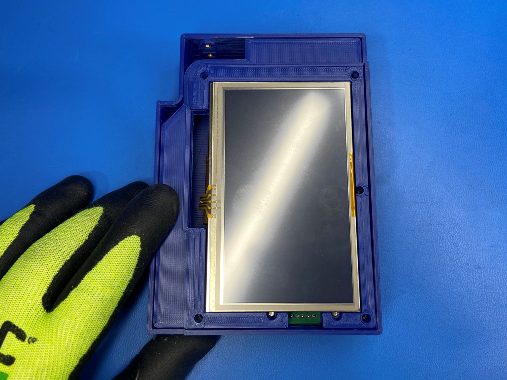
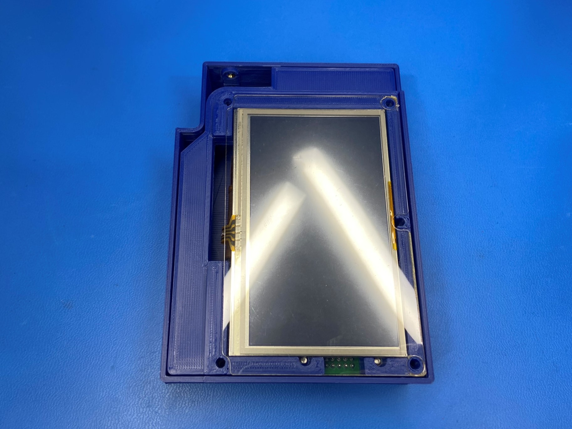
Place the assembly inside the LCD Case [PP-GP0458] make sure the side that has the three holes is positioned on the right side.
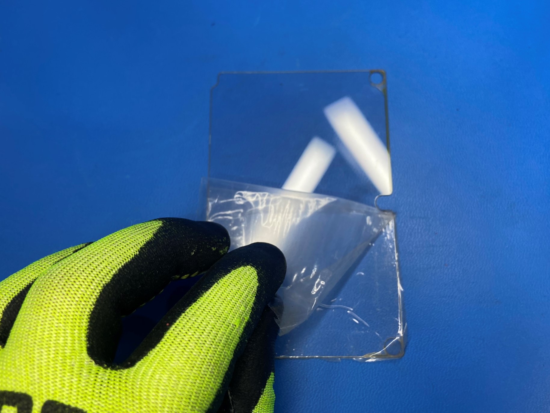
Remove the protective film from both sides of the plastic laser cut LCD cover [PP-FP0183] be careful not to scratch the LCD cover.
Once the protective film is removed for the LCD cover place it over the touch screen.
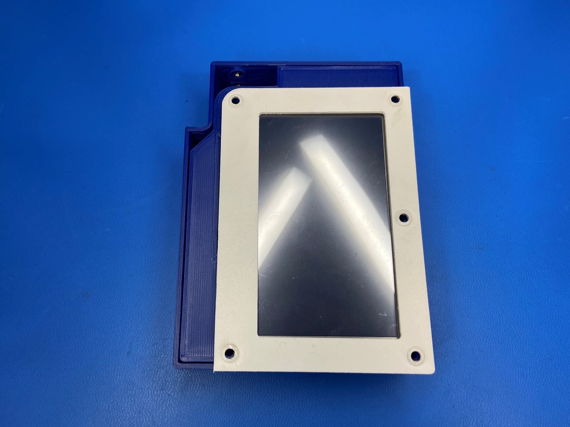
Place the touch screen bezel cover [PP-FP0174] over the LCD cover making sure all the holes are aligned. Then attach it to the LCD case using 5x M3x16 BHCS [HD-BT0256] with M3 washers [HD-WA0038]

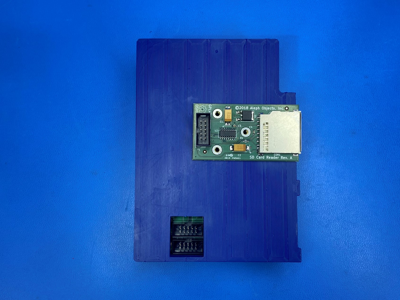
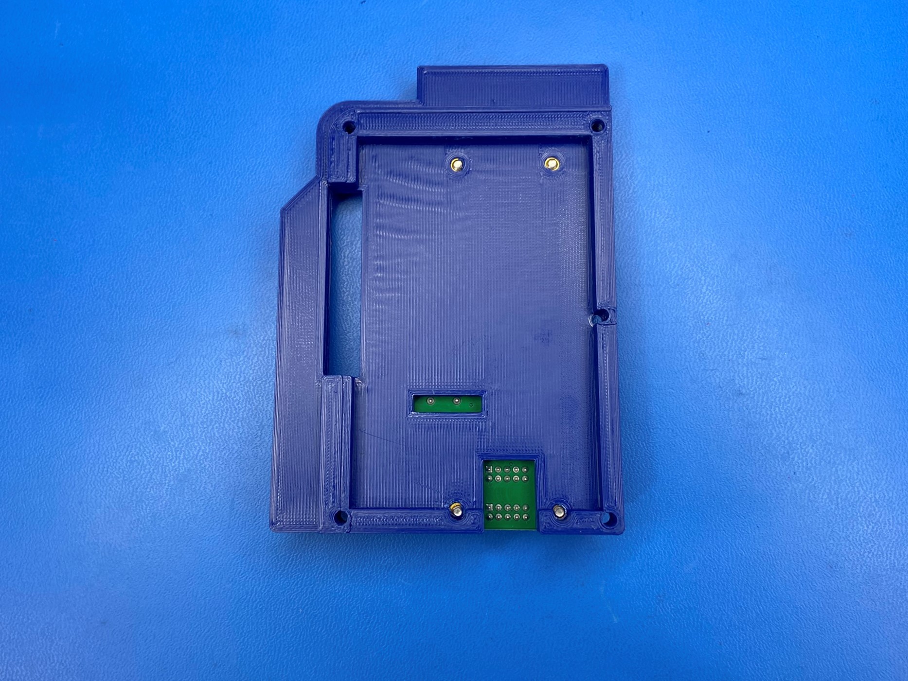
Flip the assembly over so that the backside of the LCD case is facing up. Then place the PCB SD reader [PC-BD0124] over the three brass inserts.
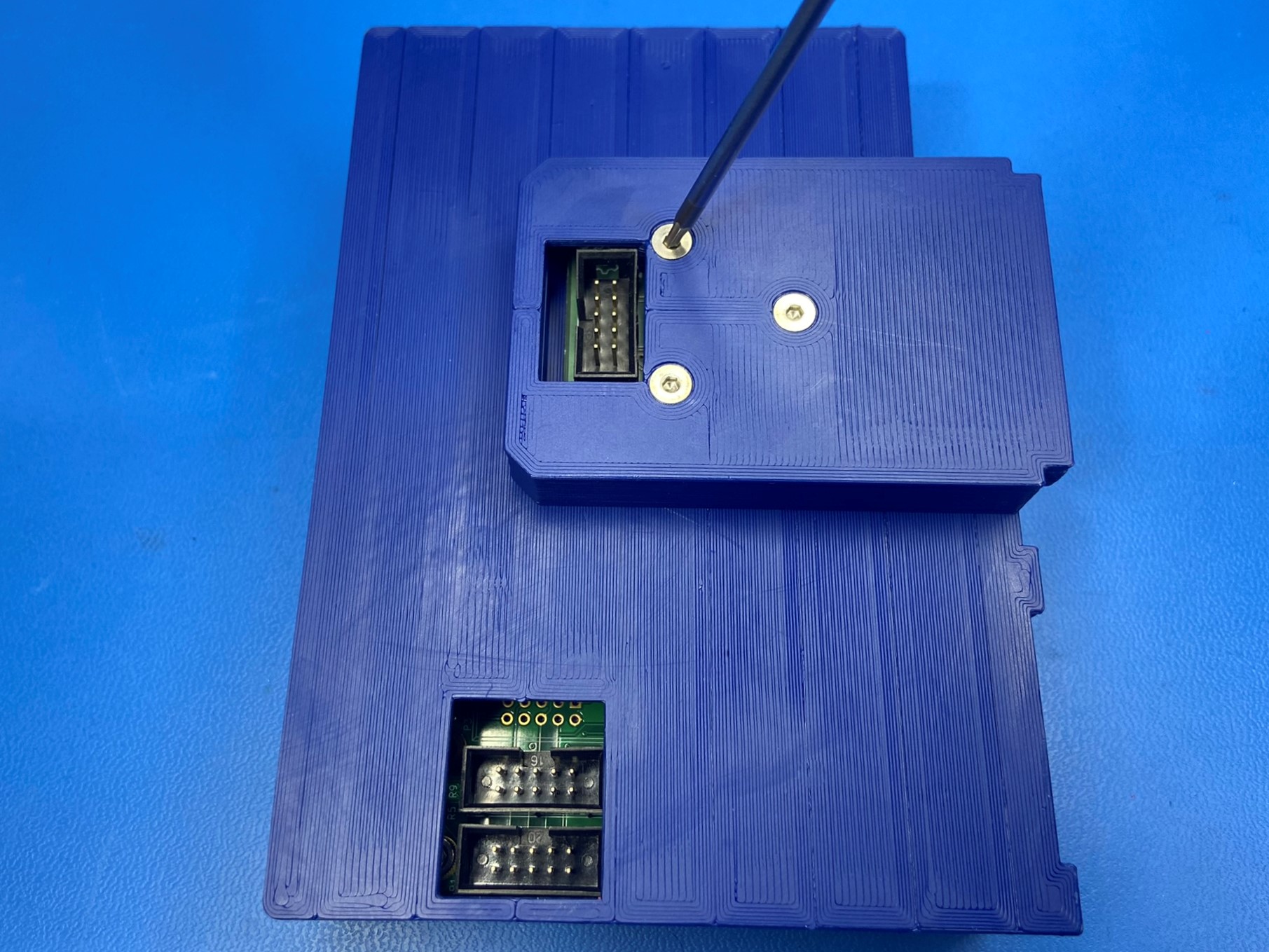
Then take the SD mount [PP-GP0472] and place it over the PCB SD reader making sure the three holes align with the brass inserts. Then use 3x M3x16 FHCS [HD-BT0082] to secure the PCB SD reader and SD mount to the LCD case.