Open HardwareAssembly Instructions
Guides for installation and assembly of the LulzBot line of products made by FAME 3D LLC.
Guides for installation and assembly of the LulzBot line of products made by FAME 3D LLC.
Gather parts
Nema 17 stepper motor (EL-MT0029)
Flexible shaft coupling (HD-MS0351)
2x- M3x5 SHCS (HD-BT0044)
1x- Motor damper (EL-MS0032)
Tools needed:
1.5mm hex driver
2.5mm hex driver
Instructions:
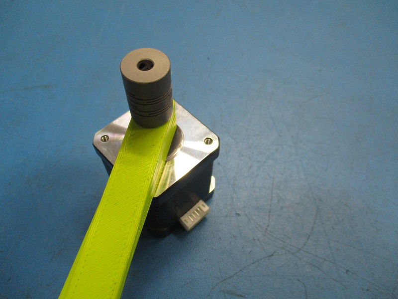
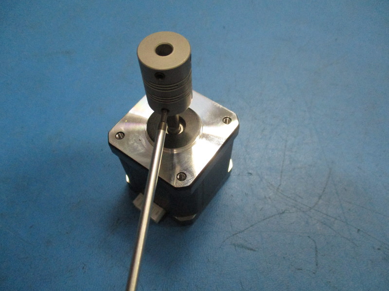
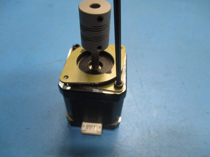
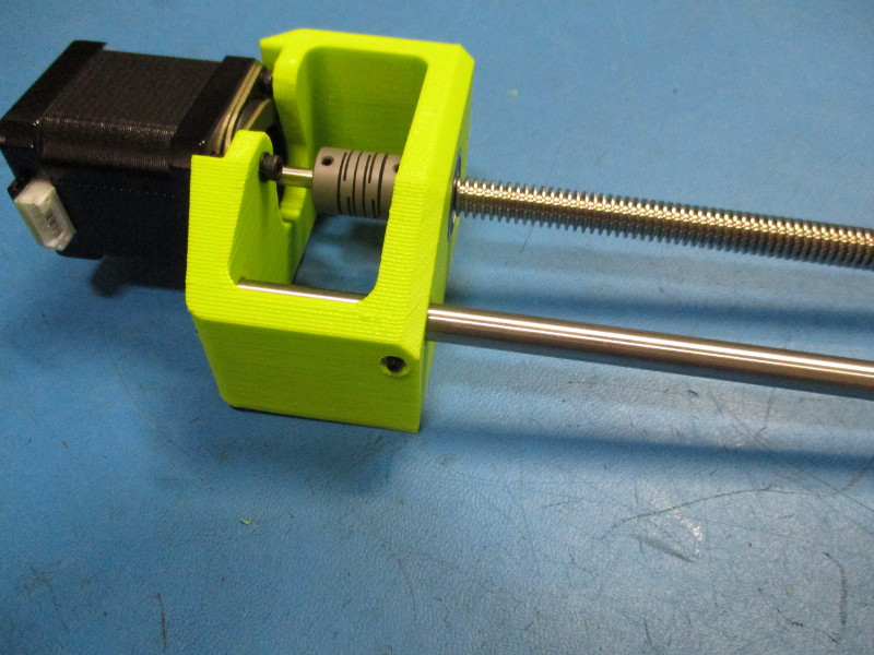
Place the flexible shaft coupling on the motor 15mm from the face of the motor. Tighten down the lower set screws against the shaft of the motor to 8in*lbs. Ensure one of the set screws is in line with the flat portion of the motor shaft.
Attach the motor damper to the motor using the two M3x5 screws. The non threaded holes of the damper need to be sitting against the motor. Note the orientation of the damper on the motor.
Installing Z lower right
Gather parts
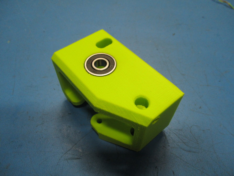
1x- Z lower right (AS-PR0051)
2x- M3x10 SHCS (HD-BT0005)
2x- M3 black oxide washer (HD-WA0038)
1x- M3 set screw (HD-BT0012)
Tools needed:
2.5mm hex driver
1.5mm hex driver
Instructions:
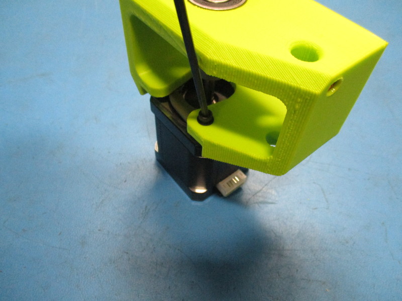
Install the Z lower right onto the motor. Note the orientation of the Z lower right on the motor. Fasten two M3x10 SHCS screws with black oxide washers into the holes that align with the damper. Torque to 5in*lbs.
Insert the M3 set screw into the threaded insert at the front of the Z lower right.

Gather parts
8mm Smooth rod, 315mm (HD-RD0035)
Drive rod 10mm (HD-RD0037)
Tools needed:
Instructions:
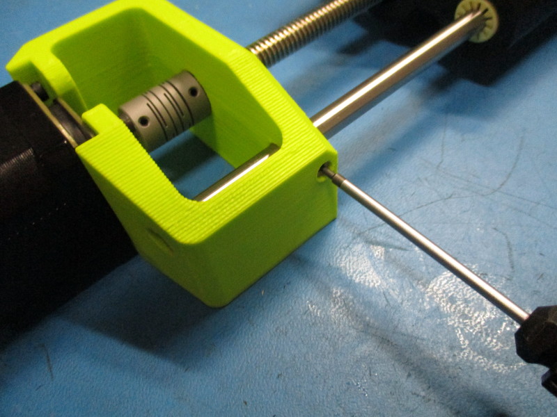
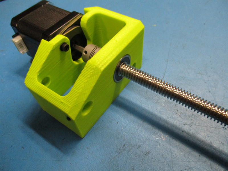
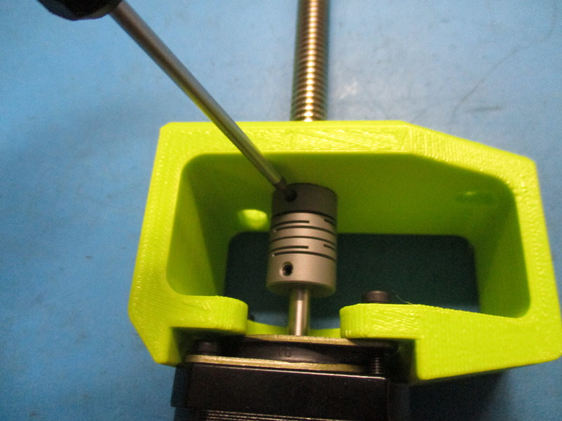
Insert the shouldered end of the drive rod into the bearing so that the flat portion is in the flexible rod coupling. Tighten the set screws in the flexible rod coupling onto the flat portion of the drive rod. Torque to 5in*lbs
Insert the 8mm smooth rod into the Z lower right
Gather parts
1x- X end idler assembly (AS-PR0052)
3x- M5 black oxide washer (HD-WA0040)
3x- M5x10 SHCS (HD-BT0048)
1x- 10mm x 2mm Flange mount supernut (HD-NT0047)
Tools needed:
Instructions:
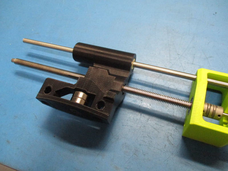
Line the smooth rod up with the pre inserted polymer bearings in the X idler end, and the drive rod up with the center hole of the X idler end. Note orientation of the X idler end on the drive and smooth rods. Slide the X idler end about halfway down the rods. Run the 10x2mm flanged mount supernut down the drive rod so that the base of the supernut sits against the X idler end and the holes line up. Fasten using three M5x10 screw with black oxide washers. Torque screws to 8in*lbs.
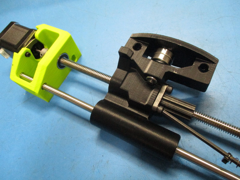
Gather parts
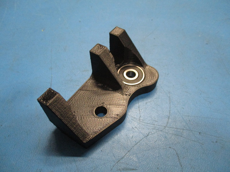
627 bearing (HD-MS0277)
Z upper right (AS-PR0050)
Tools needed:
Instructions:
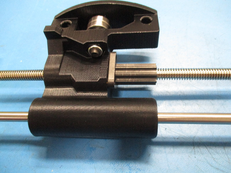
Press the 627 bearing into the bearing pocket on the Z upper right.
Install the Z upper right onto the smooth and drive rods. The drive rod will press into the 627 bearing and the smooth rod will press into the Z upper right. Ensure the smooth rod is flush with the top of the Z upper right.
Tighten the set screw on the Z lower right to 2in*lbs