Open HardwareAssembly Instructions
Guides for installation and assembly of the LulzBot line of products made by FAME 3D LLC.
Guides for installation and assembly of the LulzBot line of products made by FAME 3D LLC.
Gather parts
1x- Z Lower Left mount (AS-PR0045)
1x- Z Upper Left (AS-PR0044)
1x- X End Motor assembly (AS-PR0046)
2x- NEMA 17 Stepper Motor (EL-MT0029)
1x-Helical flexible shaft coupling (HD-MS0351)
1x-Timing pulley (HD-MS0033)
1x-Nema 17 stepper motor damper (EL-MT0032)
4x- M3x12 SHCS (HD-BT0039)
2x- M3x10 SHCS (HD-BT0005)
2x- M3x5 SHCS (HD-BT0044)
1x- Smooth Rod (HD-RD0035)
1x- Drive Rod (HD-RD0037)
1x- Z Drive Nut (HD-NT0047)
2x- Momentary switch (EL-SW0022)
1x- 627 bearing (HD-MS0277)
1x- X/Extruder Cable harness(EL-HR0108)
3x- M5 x 10mm Socket Head Cap Screw (HD-BT0048)
4x- M3 x 6mm Flat Head Socket Cap (HD-BT0128)
3x- M3 Set Screw (HD-BT0012)
4x- M2 x 10mm Socket Head Cap Screw (HD-BT0107)
3x- M5 Washer (HD-WA0040)
6x- M3 Washer (HD-WA0038)
4x- M2 Washer (HD-WA0012)
5x- 8” cable tie (HD-MS0058)
Tools Required
Flush wire cutter
1.5 mm hex driver
2.0 mm hex driver
2.5 mm hex driver
4 mm hex driver
2in*lbs torque driver
5in*lbs torque driver
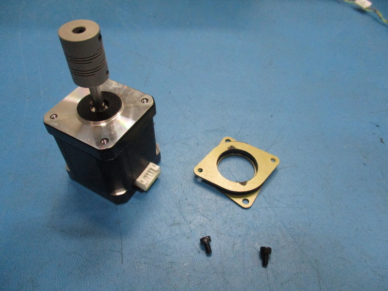
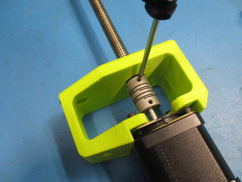
Attach a flexible shaft coupler to the motor, offset the coupler 15mm from the face of the motor, ensure one of the coupler set screws is aligned with the flat segment of the motor shaft, secure coupler in place with two set screws already installed in the coupler, tighten screws to 5 in*lbs
Attach a motor damper to the motor with 2x- M3x 5 SHCS black oxide, note orientation of the damper in relation to the connector on the motor, tight screws to 8in*lbs
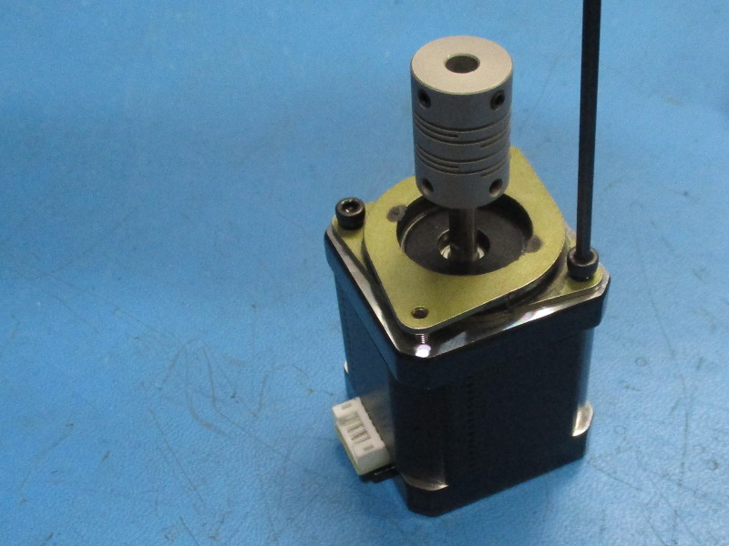
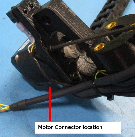
Align the Z motor with the Z lower left (orientation is critical) the motor connector is to be facing toward the front of the Z lower left part
Attach the motor to the Z lower left with 2x- M3x 10 SHCS black oxide and 4x- M3 washers black oxide, tighten screws to 8 in*lbs

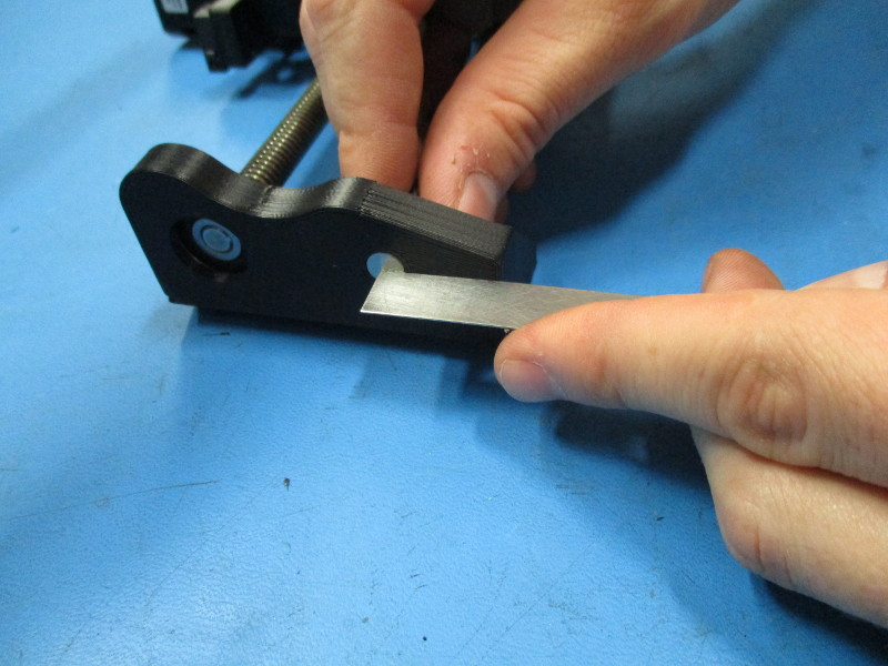
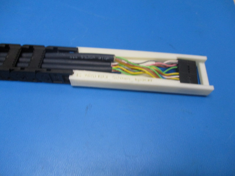
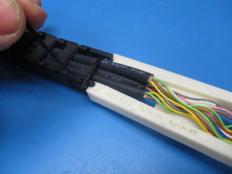
Set the 20 position connector at the Extruder end of the cable harness to 80 mm from the back of the connector the end of the cable chain, using the printed jig. Secure the cable in place with a cable tie
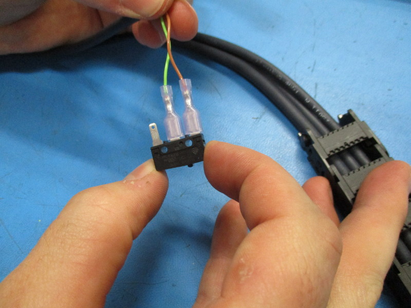
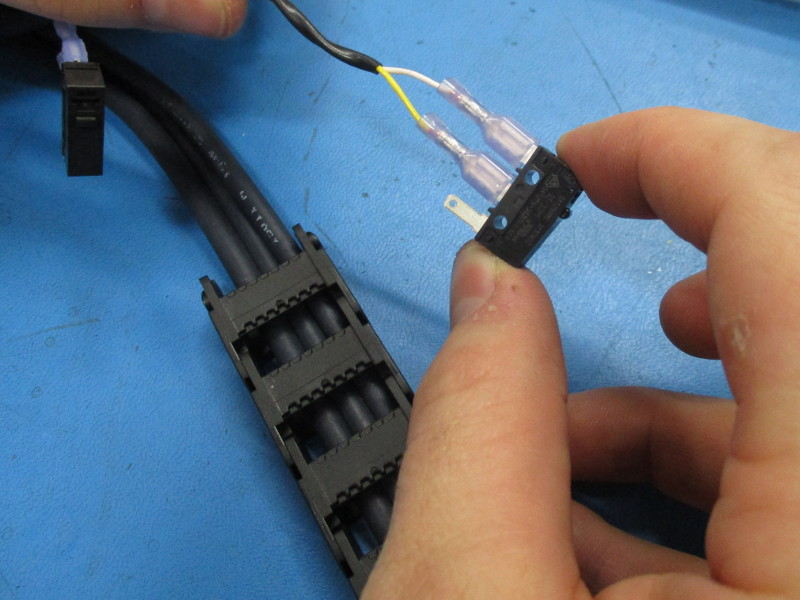
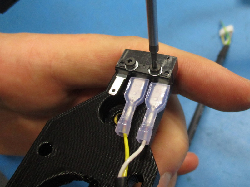
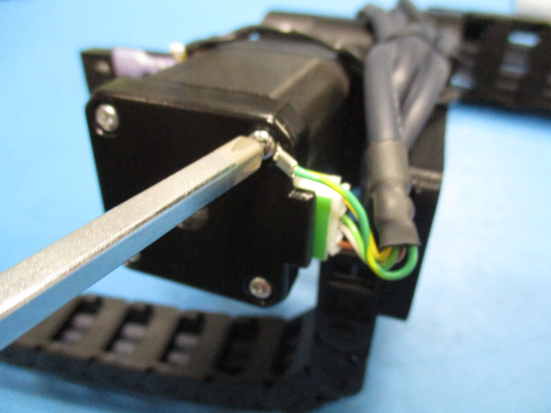
Connect Brown & Green wires to a end stop switch , connect Yellow & White wires to a end stop switch (see images, position relative to the actuator bottom on the switches is critical)
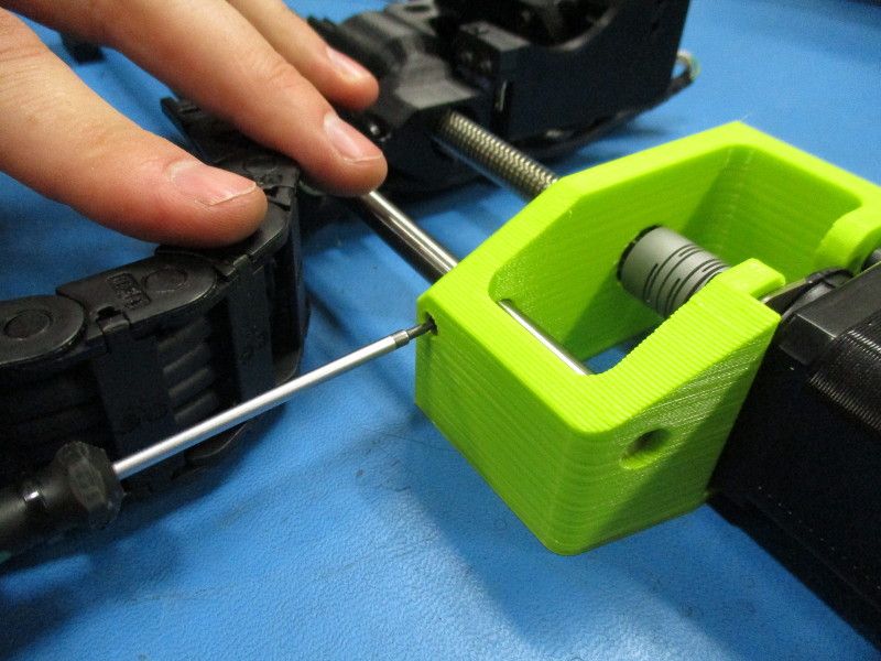
Connect the 30mm cable chain mount to the X carriage motor part (Motor mount side), use 2x M3x 6 FHCS black oxide screw, tighten to 5 in*lbs
Connect another 30mm cable chain mount to the X carriage motor part (Drylin bearing side), use 2x M3x 6 FHCS black oxide screw, tighten to 5 in*lbs
Connect the open end of the chain (opposite end of the chain where we secured the wires to the chain) to the cable chain mount near the motor mount
Route the three wires around the X carriage motor part, connect the second segment of the cable chain to the cable chain mount attached to the other end of the X carriage assembly
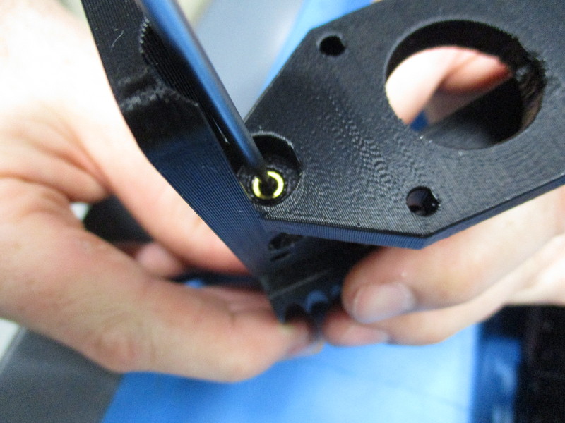
Align and install the end stop switch (Brown & Green wires) with the switch mount located in the middle of the X carriage Motor part, Secure the switch with 2x- M2 x 10 SHCS and M2 SS washers, tighten screws to 3 in*lbs
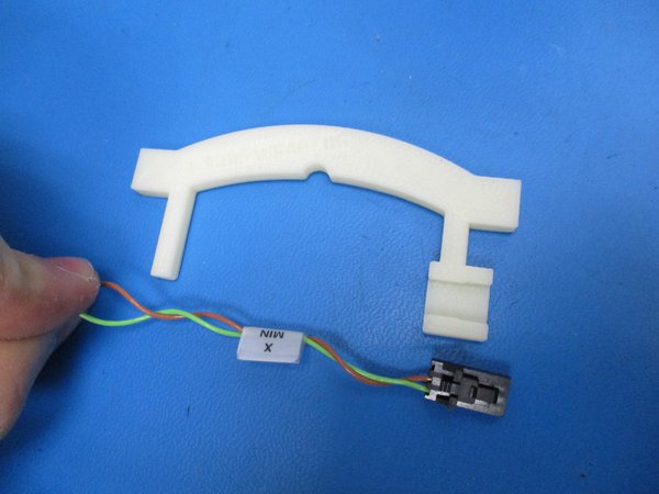
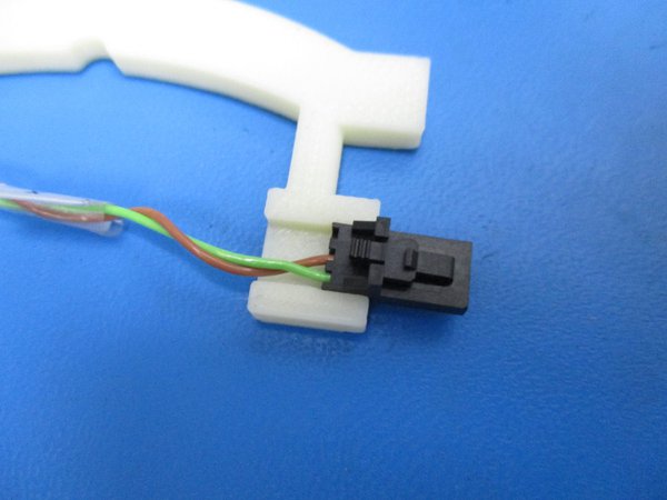
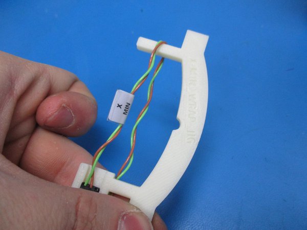
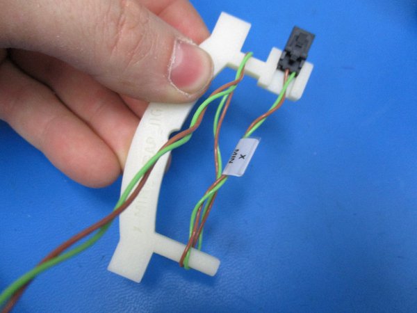
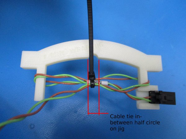
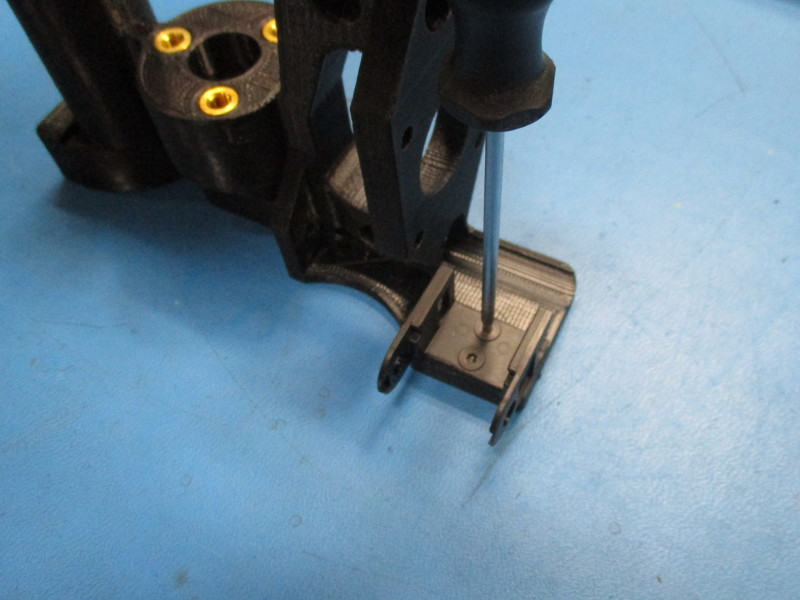
Snap the molex connector into the jig as shown. Wrap the wire around the far post on the jig and run the wire back to the post closest the molex housing. Wrap the wire around the post closest to the molex housing and run the wire back to the far post. Cable tie the center of the wrapped wires, designated by the half circle in the jig
Align and install the end stop switch (Yellow & White wires) with the switch mount located above the motor mount of the X carriage Motor part, Secure the switch with 2x- M2 x 10 SHCS and M2 SS washers, tighten screws to 3 in*lbs
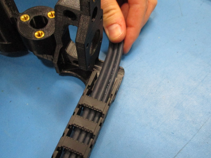
Align the wires (previously wrapped around the X carriage) with the scalloped features of the X carriage Motor
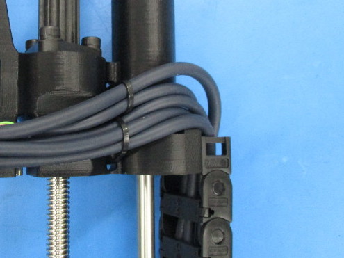
With a cable tie secure (the cable tie latch must be on the opposite side of the X carriage Motor than the wires) the three lower wires and one upper wire to the lower cable mount area of the X carriage motor
With a cable tie secure (the cable tie latch must be on the opposite side of the X carriage Motor than the wires) the remaining upper wire to the upper cable mount area of the X carriage motor
With a cable tie secure (the cable tie latch must be on the opposite side of the X carriage Motor than the wires) the five wires to the cable mount area nearest the Motor mount if the X carriage motor.
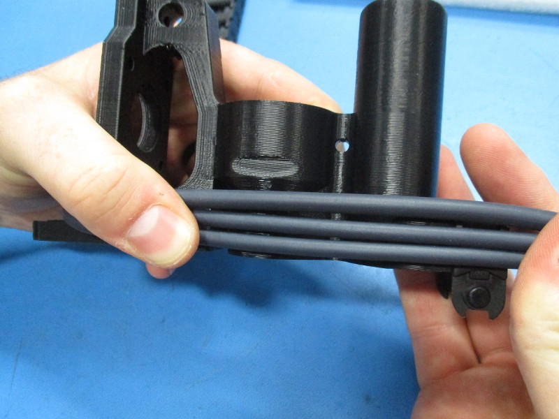
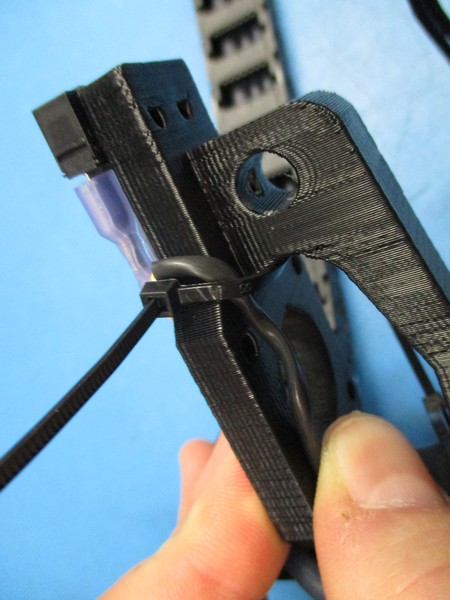
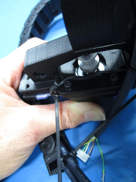
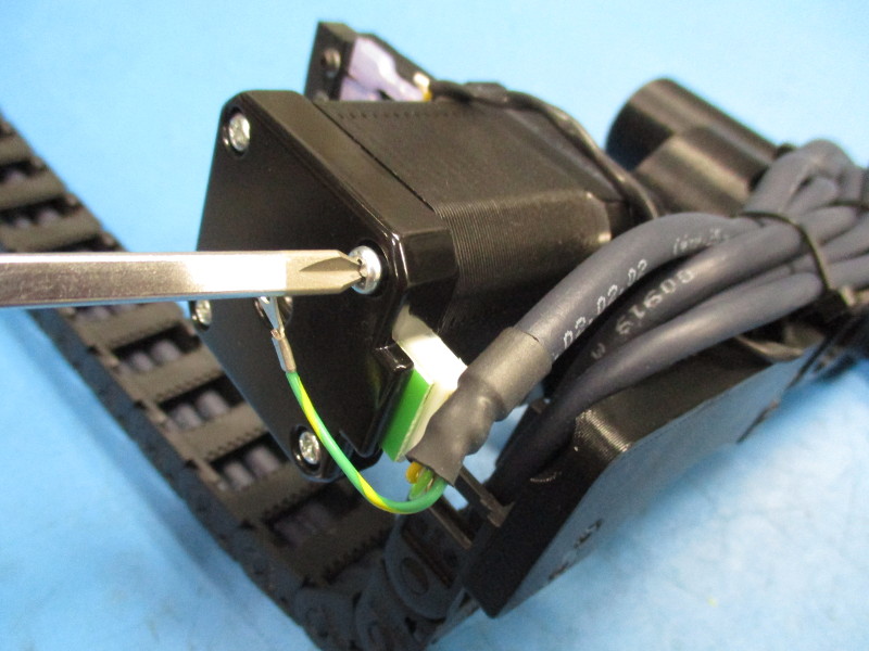
With a cable tie secure the Zmax endstop wires along the edge of the x end motor as pictured. Be sure the zip tie is under the quick connect terminals on the endstop side.
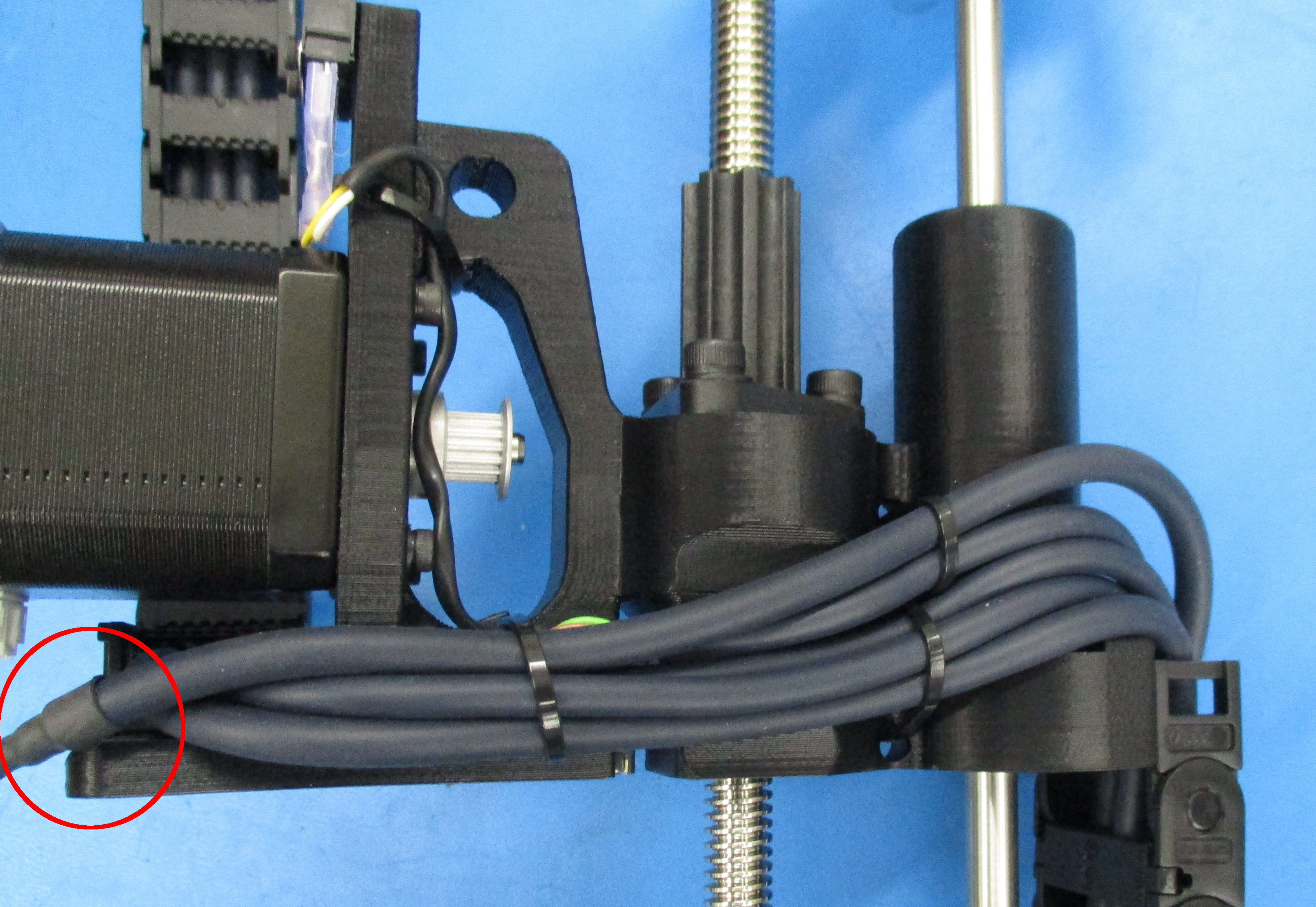
All cables must be tightly secured and as close to the X carriage Motor as possible to prevent the cables from rubbing on the frame.
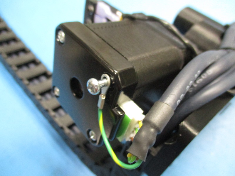
Note: The X motor cable's heatshrink should be aligned with the back of the X end motor as pictured.
Cut off any remaining cable tie length past the cable tie latches.


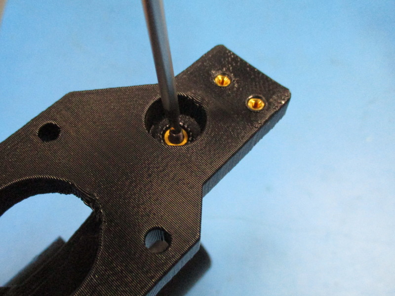
Install a M3 set screw three screw threads deep in the upper and lower rod mount inserts on the X Carriage Motor part
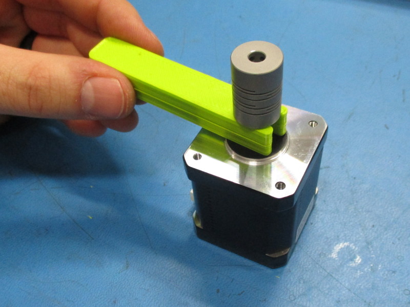
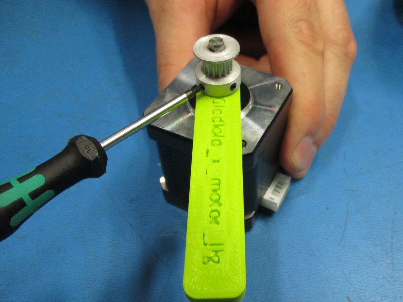
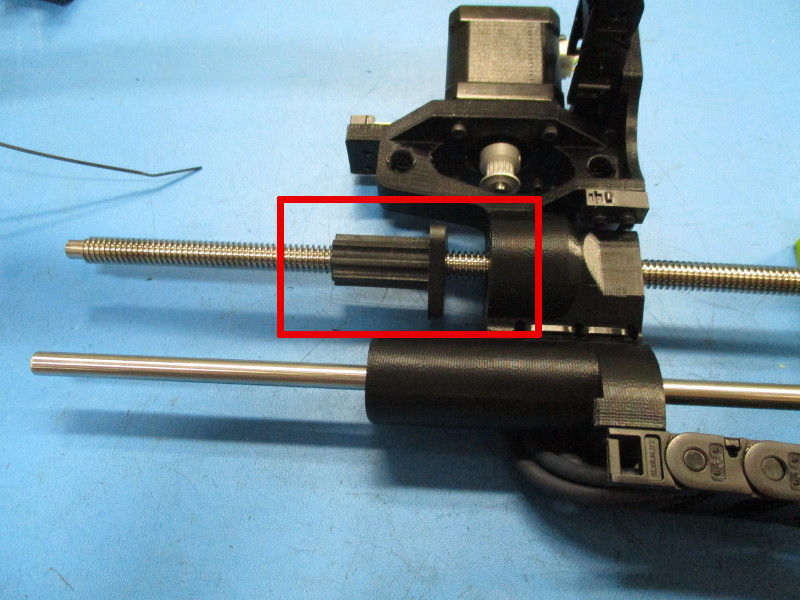
Attach a pulley to the motor, offset the pulley 10mm from the face of the motor, ensure one of the pulley set screws is aligned with the flat segment of the motor shaft, secure pulley in place with two set screws already installed in the pulley, tighten screws to 2.5 in*lbs
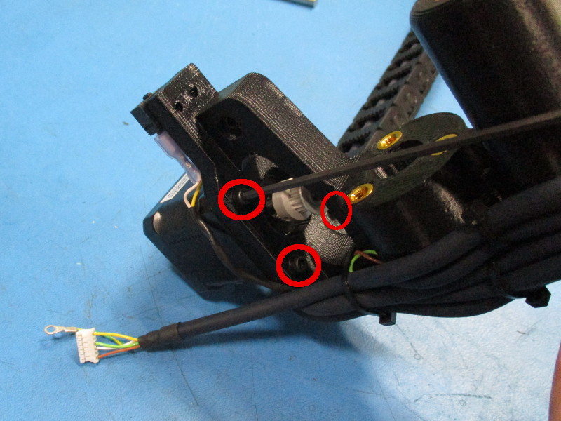
Attach the motor, motor connector oriented down toward the bottom of the X Carriage Motor assembly) to the X Carriage Motor assembly with 4x- M3x 12 SHCS Black oxide and 4x- M3 washer black oxide, tighten screws in 8 in*lbs
Remove one of the X Carriage motor case screws, install the screw into the ring terminal from the motor cable, re-install the screw until the head is again recessed and tight. With the motor oriented so the connector is pointing down, the motor screw location to the right of the motor connector is the only allowable location for this mounting.
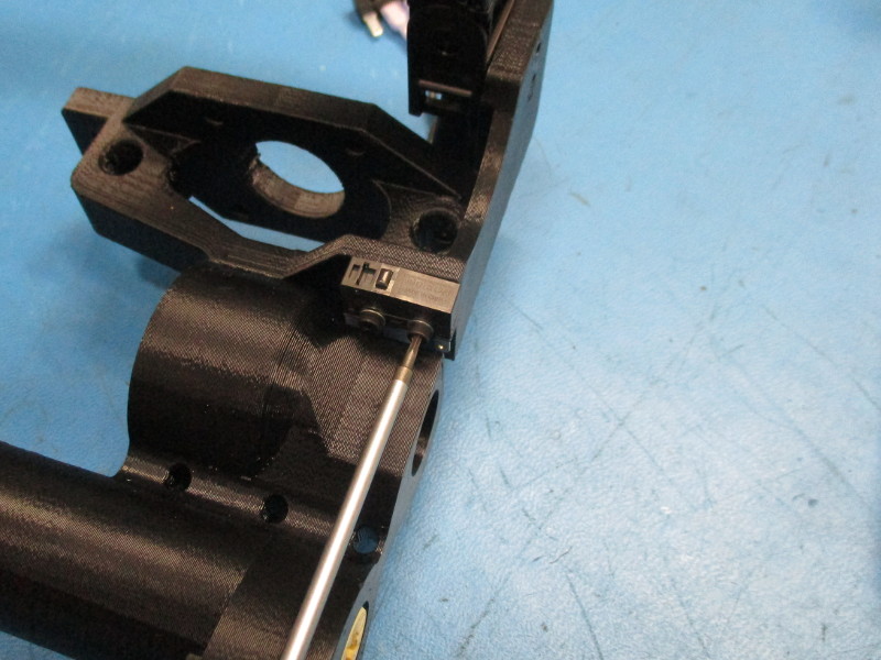
Install a drive rod into the Z lower 627 bearing ensuring the drive rod extension enters the flexible shaft coupler, the drive rod shoulder must sit flat against the 627 bearing face, align the flat face of the drive rod shoulder with one of the set screws in the coupler, tighten both set screws to 5 in*lbs
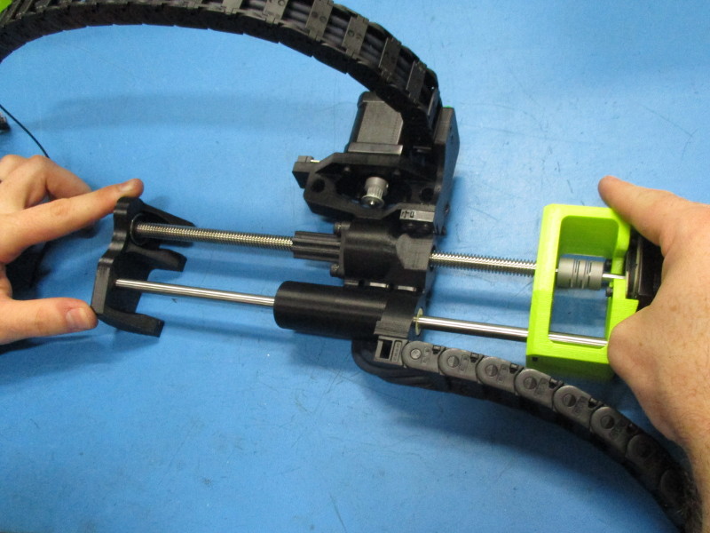
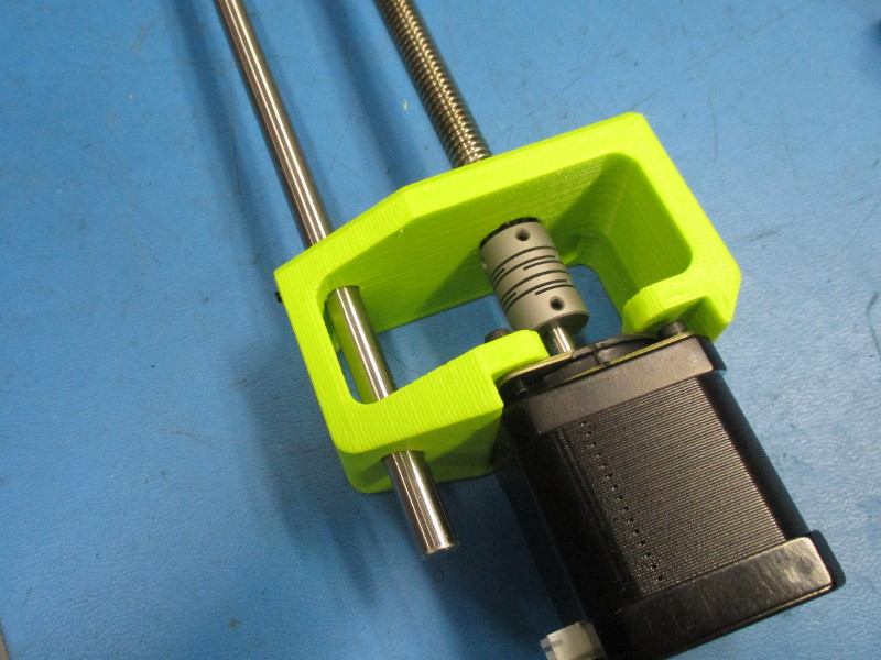
Install a Smooth Rod into the Z lower for approximately 30mm of the rod to extend downward in the direction of the motor
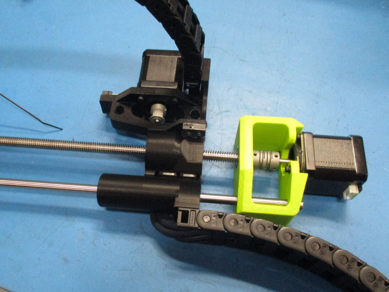
Install the X Carriage Motor assembly (with cables, switches, and motor attached) onto the Z Lower Left, Drive Rod, and Smooth rod assembly, position the X carriage Motor assembly just above the Z lower left
Screw the Z nut onto the Drive rod, position the rod approximately 200mm from the top of the drive
Attach the Z nut to the X Carriage assembly using 3x- M5x 10 SHCS Black Oxide and 3x M5 washer black oxide, loosely secure each screw then tighten to 8 in*lbs

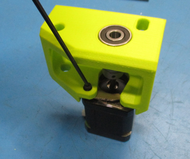
Install 627 bearing into the bearing pocket in the Z Upper Left part
Align and install the Z upper Left onto the Drive Rod and Smooth rod, the bearing race in the Z upper left must sit flush on the shoulder of the drive rod,
Position the smooth rod so the top of the rod is flush with the top of the Z Upper left
Secure the M3 set screw that is in the Z Lower Left/ motor assembly, tighten the screw to 3 in*lbs